Sensys Networks NODE-LP FlexNode Line Powered Radio User Manual 2
Sensys Networks, Inc. FlexNode Line Powered Radio 2
Contents
- 1. User Manual - 1
- 2. User Manual - 2
User Manual - 2
1608 4th Street Suite 200 Berkeley CA 94710 | www.sensysnetworks.com/resources| P 510.548.4620 F 510.548.8264
Assemble
1
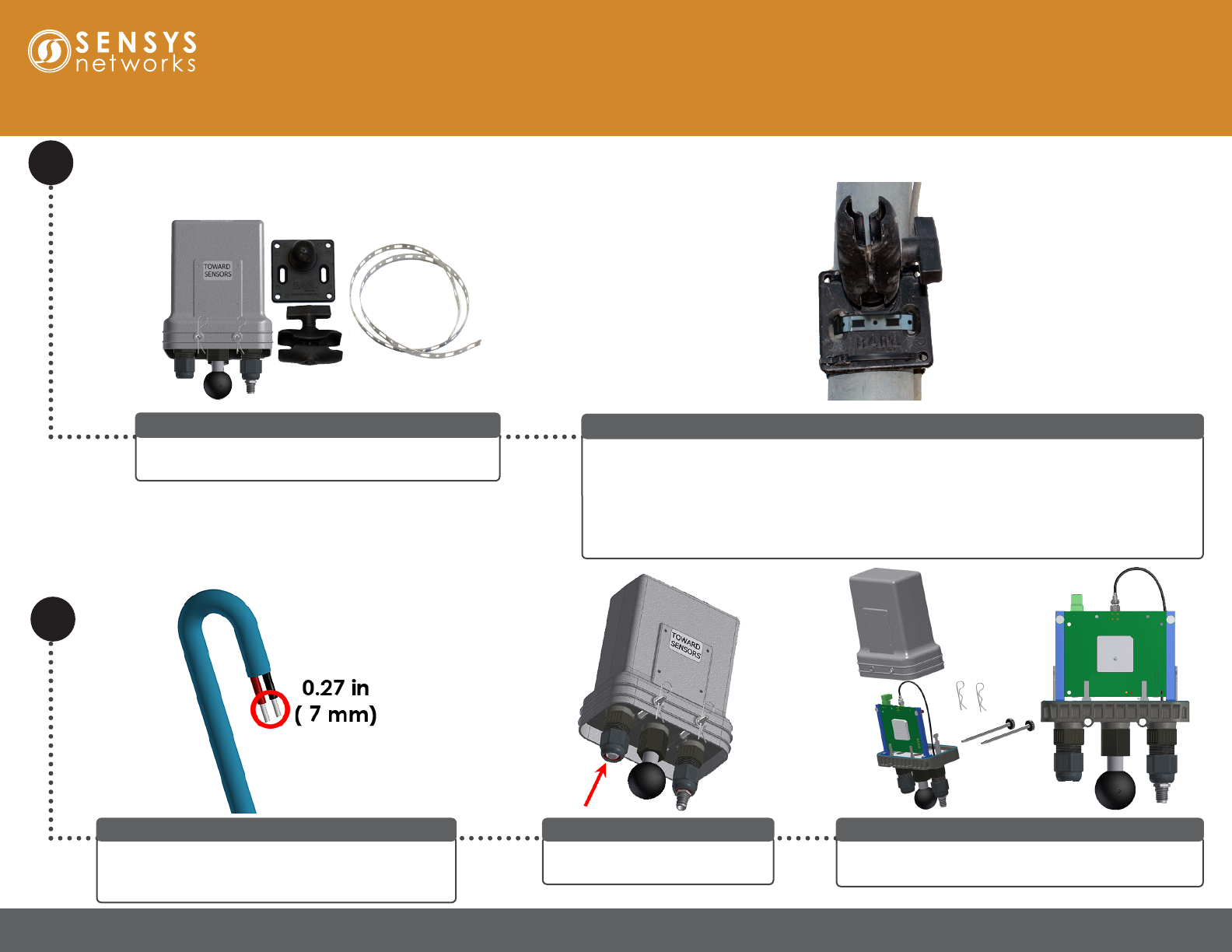
A FlexNode Line Powered assembly requires a single
FlexNode Line Powered and the mounting kit.
FlexNode Line Powered Installation Parts
Quick Start Guide: FlexNode Line Powered Radio (NA)
Pull the power cable (not provided by Sensys Networks) through the conduit to mounting
location for the FlexNode Line Powered. Ensure the power cable is not connected to the power
source. Make sure the power cable has enough slack for drip loop. Assemble the mounting plate
onto the pole. Attach mounting arm to mounting plate. Complete the remaining assembly steps
for the FlexNode Line Powered inside the bucket before attaching it to mounting arm.
Please refer to Repeater Installation Guide for detailed instructions for mounting assembly.
Prepare Mounting Location
Strip the wires to expose approximately 0.27 in (7 mm)
of the conductor from the power cable to prepare for
connecting to green terminal block inside repeater.
Strip Wires
Remove reusable cotter pins and pull out both retention
rods. Remove the FlexRepeat3 Line Powered cover.
Pull Cover Off Repeater
Remove the bulkhead connector
and remove and discard the plug.
Remove Plug
1608 4th Street Suite 200 Berkeley CA 94710| www.sensysnetworks.com/resources| P 510.548.4620 F 510.548.8264
Assemble (cont.)
Quick Start Guide: FlexNode Line Powered Radio (NA)
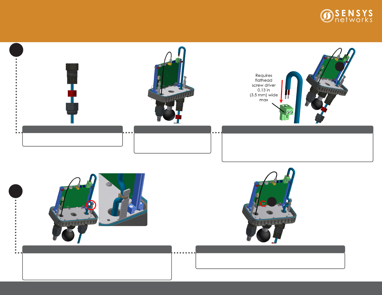
Assemble bulkhead connector from the
FlexRepeat3 Line Powered onto the power cable.
Assemble Bulkhead Connector
Thread the power cable through the
repeater to reach the green terminal
block.
Thread Power Cable
Unplug the green terminal block from (a), then thread the stripped wires
into the green terminal block and tighten screws to t snuggly with a
small at head screw driver. The terminal block has NO POLARITY
requirement (either wire can go into either location). Plug the assembled
terminal block back into its original location.
Connect Stripped Wires to Green Terminal Block
Use a cable tie to attach the power cable to one of the metal prongs on the
FlexNode Line Powered to provide strain relief and trim off excess tie.
Note: The cable tie head must face inwards to allow assembly of the
FlexRepeat3 Line Powered cover.
Cable Strain Relief
a
Connect power cable to the power source. Wait approximately ve seconds
for LED lights to blink on the circuit board to ensure unit is turned on (a).
Connect to Power Source
a
1608 4th Street Suite 200 Berkeley CA 94710| www.sensysnetworks.com/resources| P 510.548.4620 F 510.548.8264
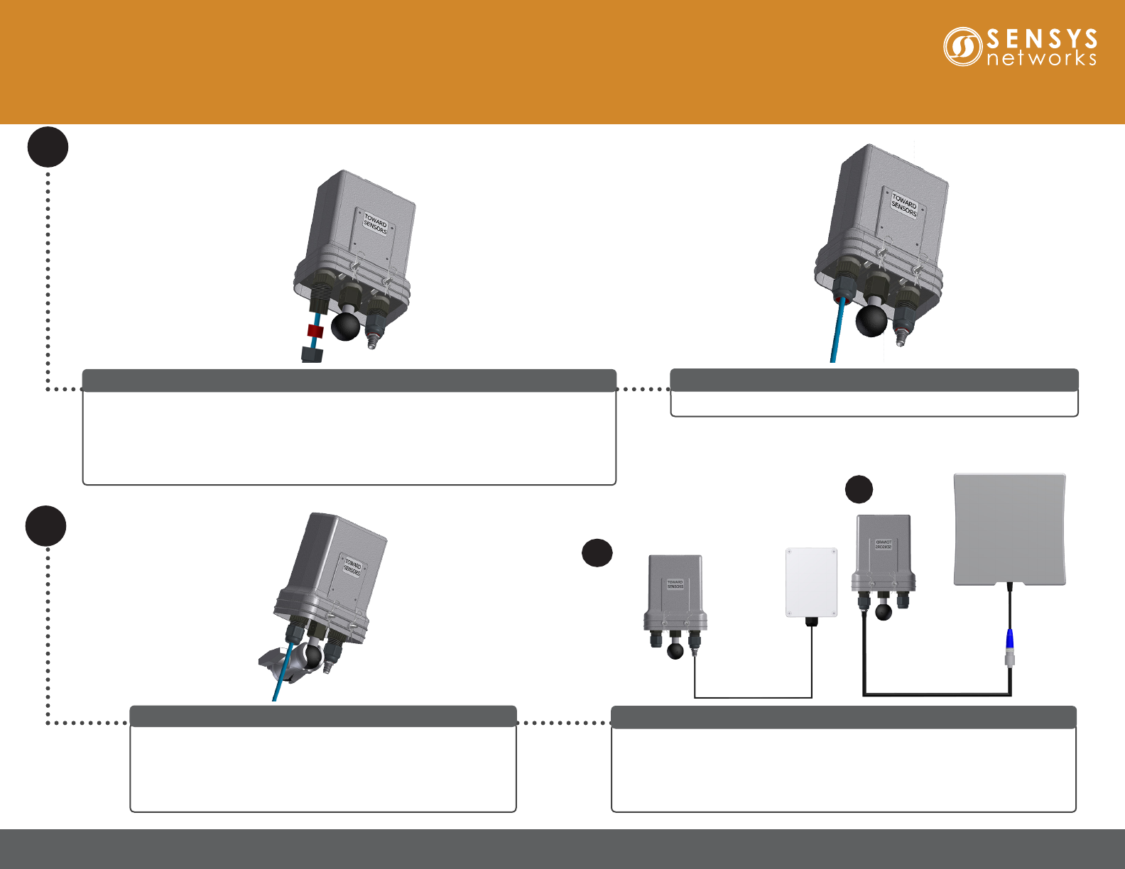
Secure Bulkhead Connector to FlexNode Line Powered
Secure bulkhead connector to the FlexNode Line Powered bottom.
Assemble (cont.)
Quick Start Guide: FlexNode Line Powered Radio (NA)
Remove the cap from the TNC connector. Connect to one of the External
Antenna options with a coax cable. Two options are supported: (a) the FLEX-
ANT-1 with the same RF range as the internal antenna and (b) the FLEX-
ANT-2 with Long Range RF range. Point the external antenna towards the
sensors. The roles of the internal and external antenna can also be switched.
Connect External Antenna (Optional)
a
b
Carefully slide cover on top of FlexNode Line Powered over base. Cover will only be able to
fit one way, flip cover if it does not slide down completely. Insert retaining rods from the
rear side until rod head is flush against cover and the end of the rod fits into the receiving
hole. Insert reusable cotter pins into holes at the end of the retaining rods to lock in rods.
Note: Orient the flat rod heads on the same side of the cover with the raised rod hole ridges.
Slide Cover On and Secure Rods
Attach the FlexNode Line Powered to the mounting arm with
the Towards Sensors side facing the sensors and the access
point. Note that the mounting arm can be oriented to adjust the
location of the FlexNode Line Powered. The FlexNode Line
Powered can also operate with an optional external antenna.
Mount FlexNode Line Powered
1608 4th Street Suite 200 Berkeley CA 94710| www.sensysnetworks.com/resources| P 510.548.4620 F 510.548.8264
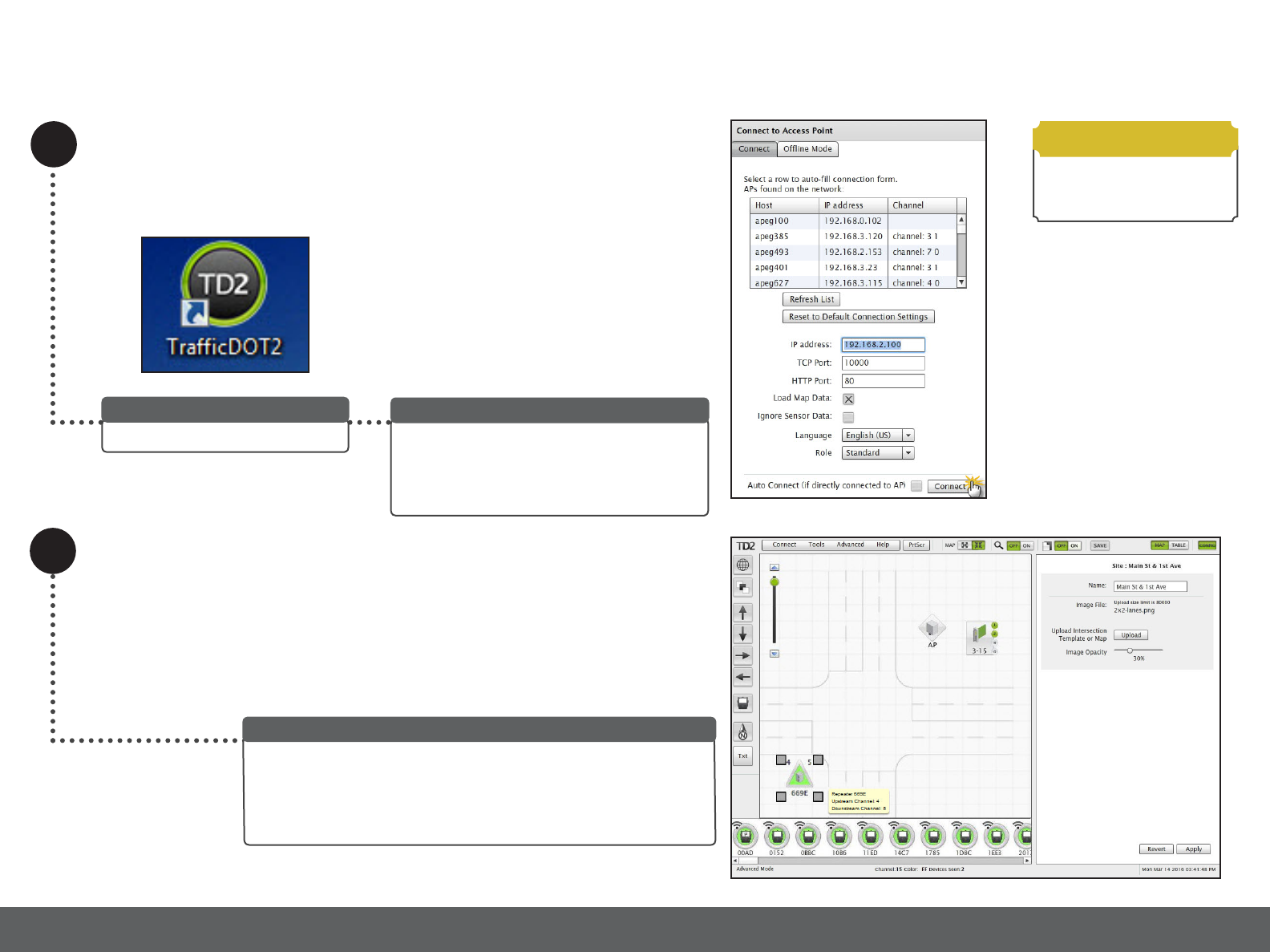
Connect to Access Point
Select an access point from the list of APCCs
and Access Points and click Connect.
Note: Ensure the box for Load Map Data is
checked before clicking Connect.
Select IP address
Click the icon to start TracDOT2.
Run TrafcDOT
2
The Main window displays. The map on the Main window populates
and congured equipment appears on the map and in the sensor tray
at the bottom of the window.
Note: Before conguring or reconguring a repeater, ensure the correct
repeater is selected on the map by verifying the serial number.
Main Window
Requirements
FlexNode Line Powered
requires TrafficDOT2
software 2.12.0 or later.
Quick Start Guide: FlexNode Line Powered Radio (NA)
1608 4th Street Suite 200 Berkeley CA 94710| www.sensysnetworks.com/resources| P 510.548.4620 F 510.548.8264
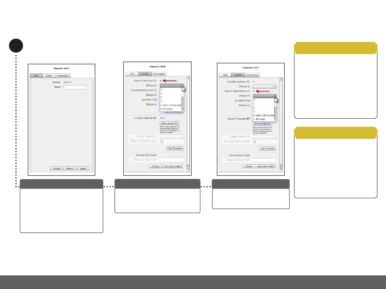
Congure Repeater
Select a repeater from the image map
to access the Repeater Conguration
window with the Info tab open. The
Name eld allows the repeater’s name
to be user-dened.
Note: Repeater’s rmware version is for
reference only.
Repeater Conguration Window
3
Select an upstream channel by clicking
the Cong tab. Select an entry for the
Current Upstream Ch eld by clicking on
the Change to drop-down list.
Specifying Upstream Channel
Select a entry for the Current
Downstream Ch eld by clicking the
Change to drop-down list.
Specifying Downstream Channel
• The default radio channel for access
point to repeater communications is 4.
• The default radio channel for repeater to
sensor communications is 5.
• Never use the same channel for
both access point and sensor
communications.
Refer to Sensys Network VDS240 Wireless
Vehicle Detection System TracDOT Set Up
and Operating Guide for more information.
Channel Notes
• When an installation contains multiple
repeaters with more than 20 sensors,
changing one or more repeaters from
Current Cong 0 to Current Cong 1
allows the access point to communicate
with up to 40 sensors through the
repeaters.
Refer to Sensys Network VDS240 Wireless
Vehicle Detection System TracDOT Set Up
and Operating Guide for more information.
Cong Notes
Quick Start Guide: FlexNode Line Powered Radio (NA)
1608 4th Street Suite 200 Berkeley CA 94710| www.sensysnetworks.com/resources| P 510.548.4620 F 510.548.8264
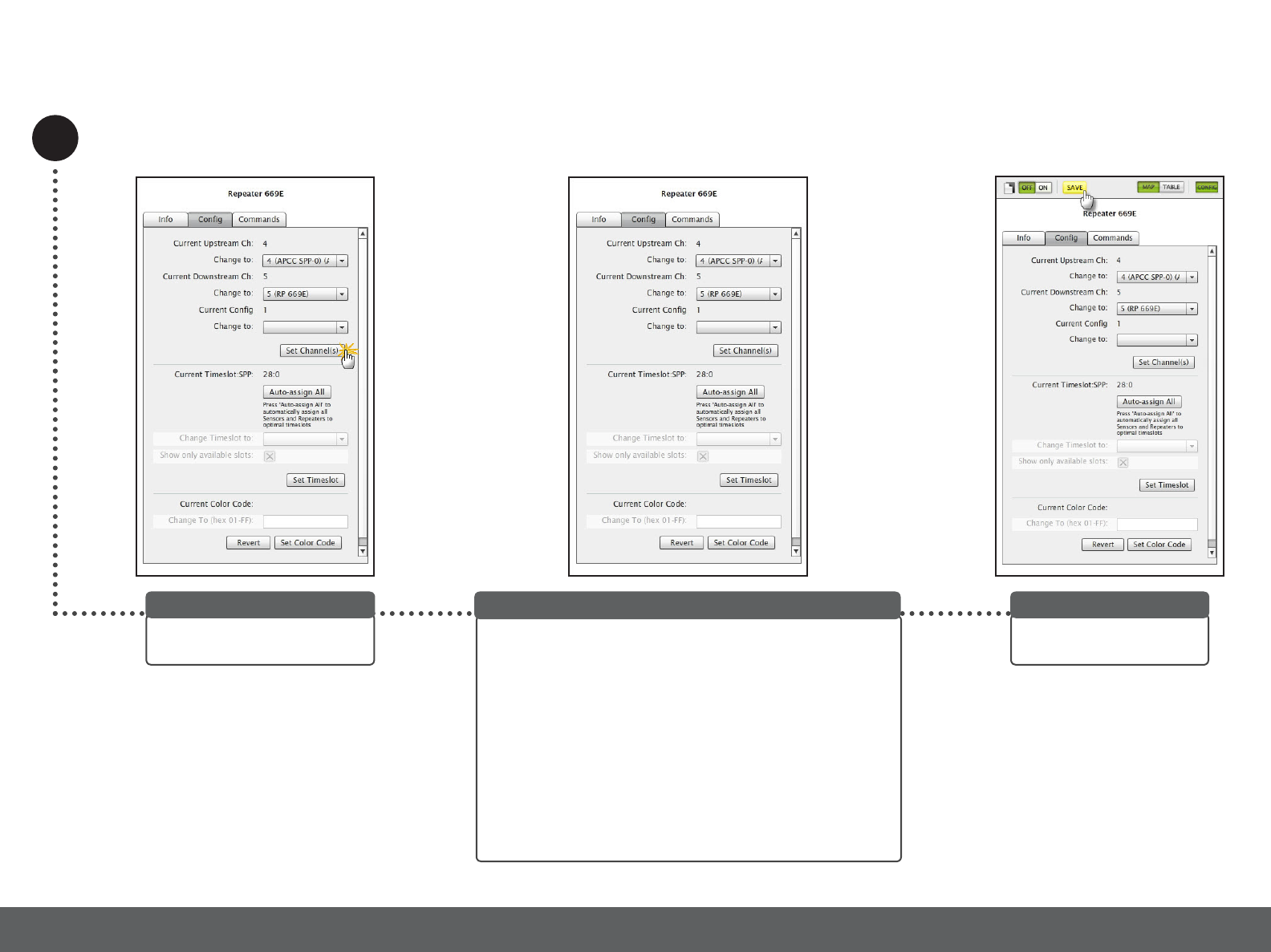
Congure Repeater (cont.)
Click SAVE to save changes
made to the access point.
Save Conguration
Click the Auto-assign All button to automatically assign all
Sensors and Repeaters to optimal timeslots.
Note: The grayed out options can be made accessible by
enabling Advanced Mode using the Advanced drop-down
menu.
To manually set the time slot, TracDOT lters the contents
of the drop-down list so that only available time slots are
displayed. Click an entry from the Change Timeslot to drop-
down list and then click Set Timeslot to accept changes.
To change the drop-down list to include all time slots in the
network (both assigned and unassigned), remove the check in
the Show only available slots.
Specifying Time Slot
Quick Start Guide: FlexRepeat3 Line Powered Repeater (NA)
Click Set Channel(s) to accept
conguration changes.
Save Conguration
Sensys Networks and the Sensys Networks logo are trademarks of Sensys Networks, Inc. All other trademarks are the property of their respective owners.
Information contained herein is believed to be reliable, but Sensys Networks makes no warranties as to its accuracy or completeness.
Copyright © 2017 Sensys Networks, Inc. • ALL RIGHTS RESERVED • CONTENTS SUBJECT TO CHANGE
Local Distributor
• A failsafe error message occurs should you
choose the external antenna option when there
is no external antenna installed.
•If FlexNode Line Powered is installed with or
without the external antenna, and the Antenna
panel options are left unchecked, the internal
antenna is used for both To AP and To Sensors
channels.
•If Discover Mode is not ON the following
warning will display: Advanced setting values
shown are either not set or last known current
value because discover not on. Value(s) will
not be updated until discover turned on.
•If Discover Mode is OFF at connection time for
TrafficDOT the Adv tab displays Not Set values.
Turn Discover Mode ON for true values to
display.
Refer to Sensys Network VDS240 Wireless
Vehicle Detection System TracDOT Set Up and
Operating Guide for more information.
Adv Tab Notes
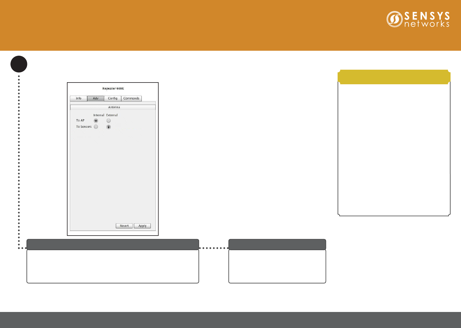
Congure Repeater (cont.)
If the repeater is connected to an external antenna, then it can be
congured via the Adv tab. From the Antenna panel, select either To
AP or To Sensors to congure an internal/external antenna.
Note: Recommended setting for external antenna is To Sensors.
Adv Tab
Click Apply to accept conguration
changes.
Click SAVE at the top of the screen to
save changes made to the access point.
Save Conguration
Quick Start Guide: FlexNode Line Powered Radio (NA)