ShenZhen WFLY Technology Development WFT09II RADIO CONTROL SYSTEM User Manual
Shen Zhen WFLY Technology Development Co., Ltd. RADIO CONTROL SYSTEM Users Manual
Contents
- 1. USERS MANUAL 1
- 2. USERS MANUAL 2
- 3. USERS MANUAL 3
- 4. USERS MANUAL 4
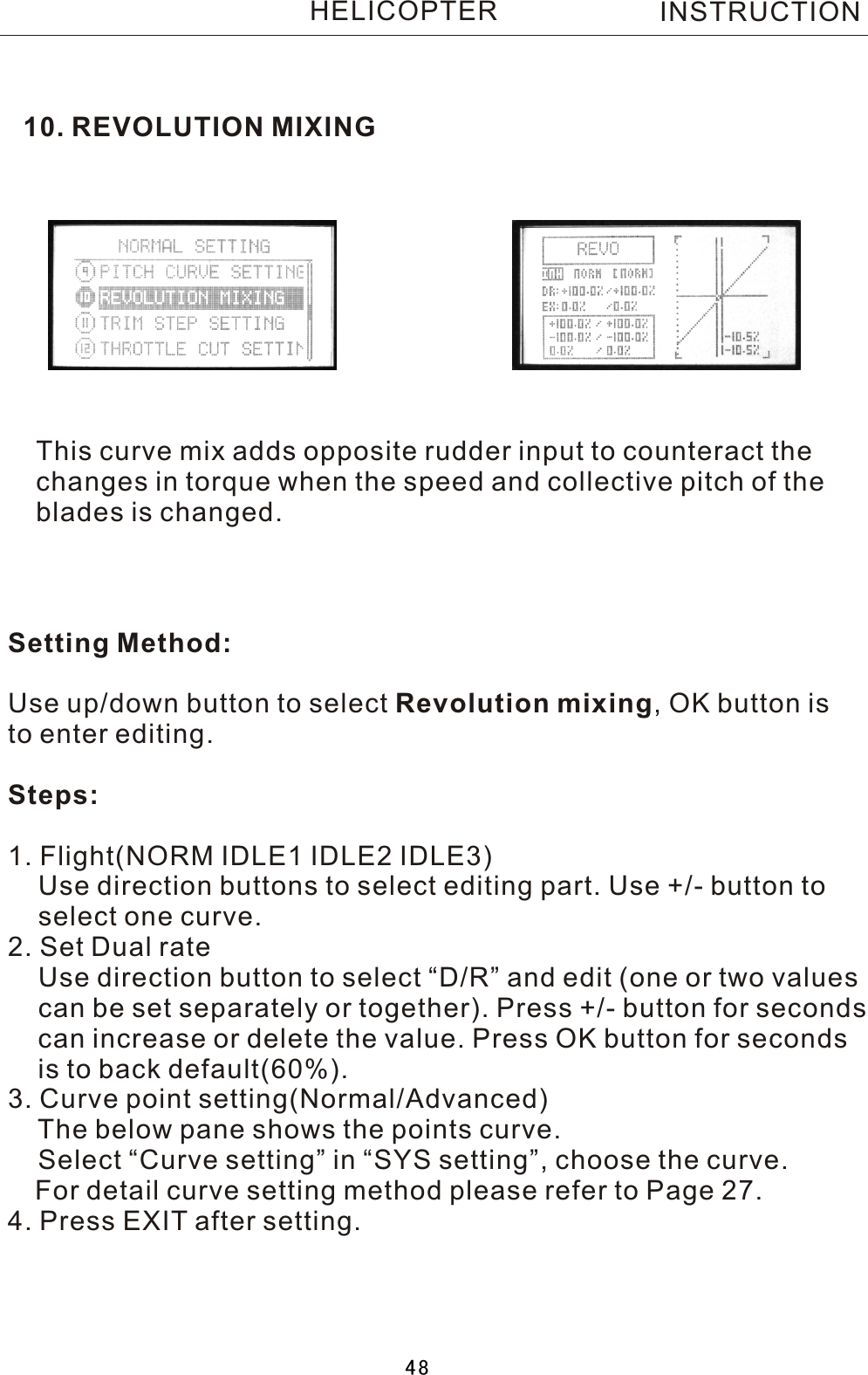
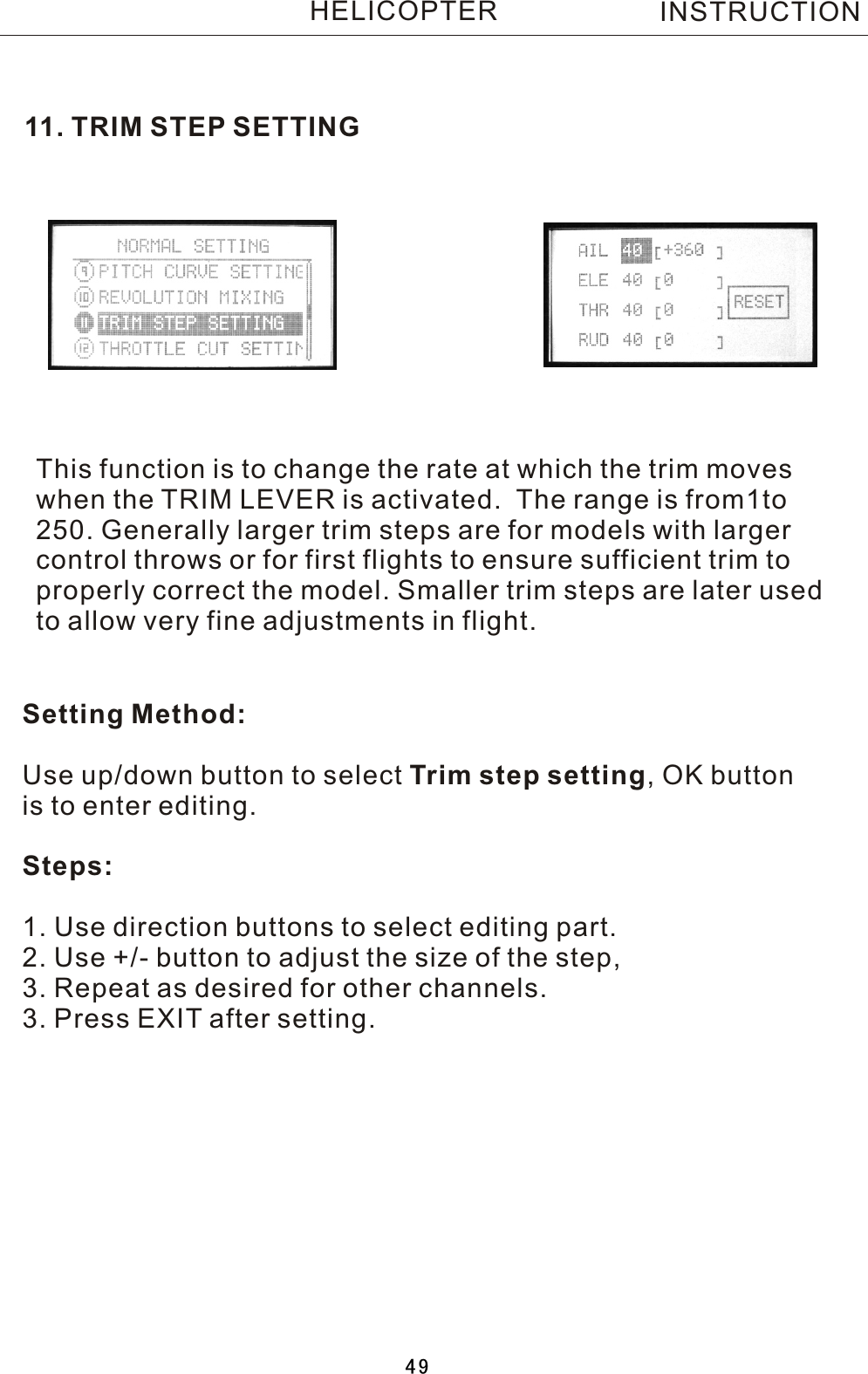
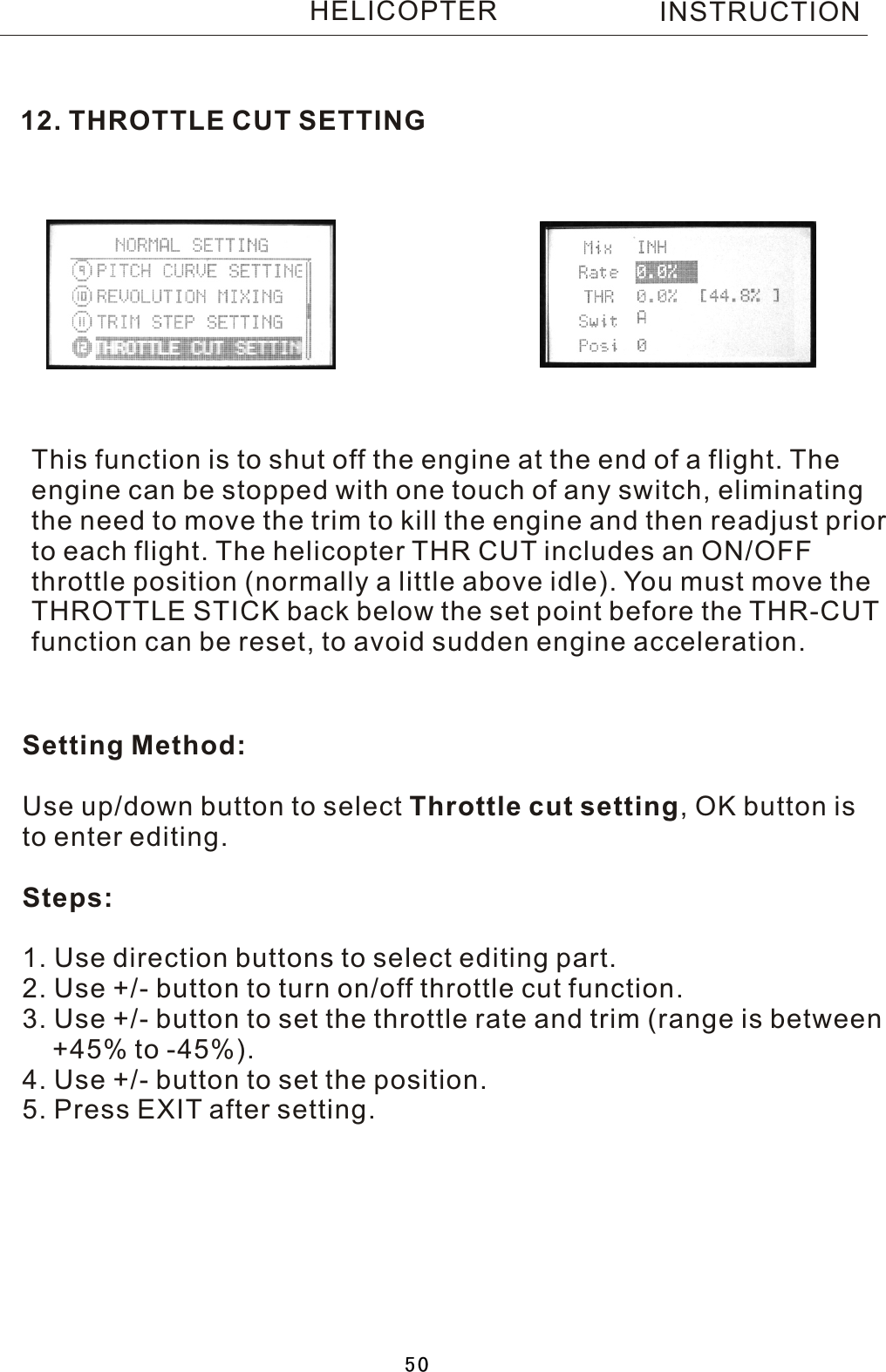
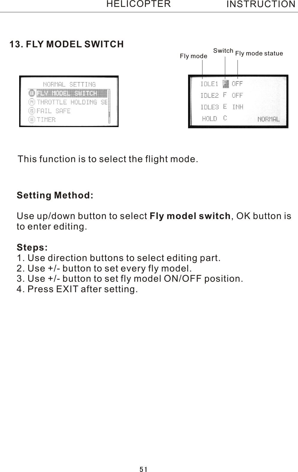
USERS MANUAL 2