ShenZhen WFLY Technology Development WFT09II RADIO CONTROL SYSTEM User Manual
Shen Zhen WFLY Technology Development Co., Ltd. RADIO CONTROL SYSTEM Users Manual
Contents
- 1. USERS MANUAL 1
- 2. USERS MANUAL 2
- 3. USERS MANUAL 3
- 4. USERS MANUAL 4
USERS MANUAL 3
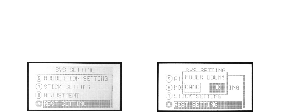
This function is to back default.
Setting Method:
Press Menu and turn on the transmitter to enter “SYS SETTING”
Use up/down button to select “RESET SETTING”, OK button is
to enter editing.
Steps:
1. Use direction button to select the editing part.
2. Press +/- button to back default.
3. Press EXIT after setting.
10.RESET SETTING
INSTRUCTION
AIRPLANE
81
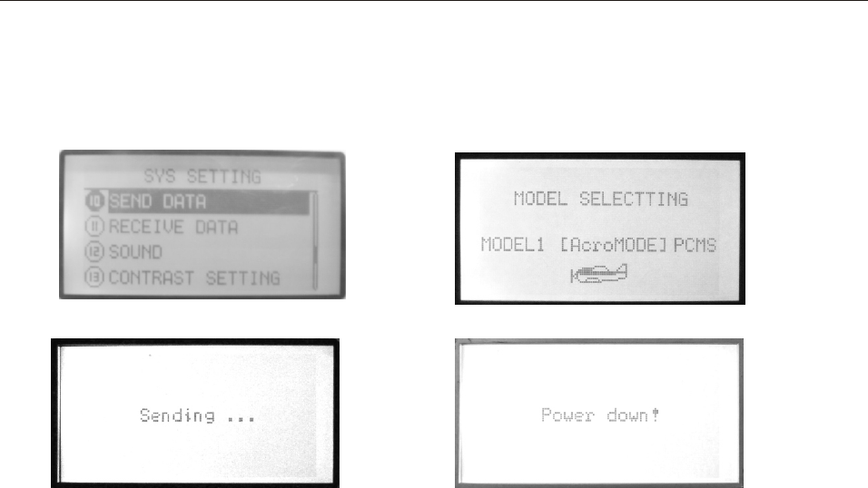
11. SEND DATA
Two transmitters (WFT09S) can copy data by a trainer cable/data
transfer cable. This function together with the next function
“Receive data” can realize the data copy.
Setting Method:
Press Menu and turn on the transmitter to enter “SYS SETTING”
Use up/down button to select “SEND DATA”, OK button is
to enter editing.
Steps:
1. Select the model data you want to send out.
2. Press OK to send.
INSTRUCTION
AIRPLANE
82
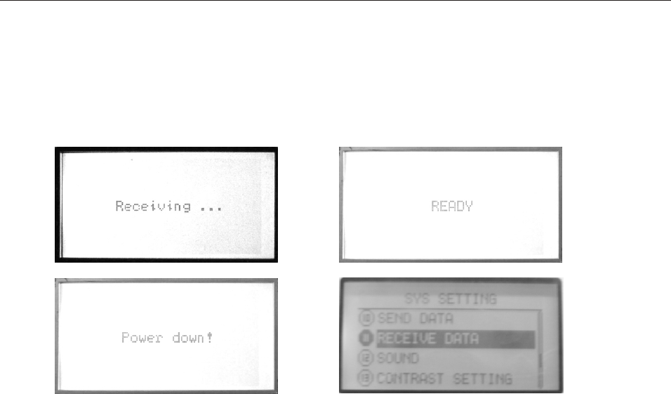
12.RECEIVE DATA
Two transmitters (WFT09S) can copy data by a trainer cable/data
transfer cable. This function together with the previous function
“Send data” can realize the data copy.
Setting Method:
Press Menu and turn on the transmitter to enter “SYS SETTING”
Use up/down button to select “RECEIVE DATA”, OK button is
to enter editing.
Steps:
1. Press OK to receive data.
2. Restart the transmitter after receiving the data and it works.
INSTRUCTION
AIRPLANE
83

This function is to select the sound ON and OFF.
Setting Method:
Press Menu and turn on the transmitter to enter “SYS SETTING”
Use up/down button to select “SOUND”, OK button is
to enter editing.
Steps:
1. Use +/- button to select ON and OFF.
2. Press OK button to confirm.
3. Press EXIT after setting.
13.Sound
INSTRUCTION
AIRPLANE
84
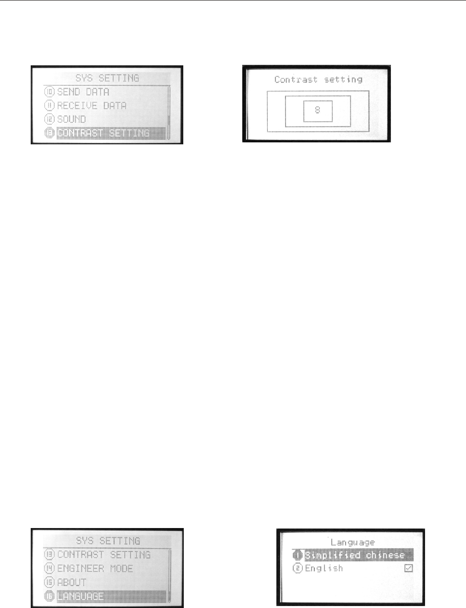
This function is to adjust the LCD brightness by increasing
or decreasing the contrast value.
Setting Method:
Press Menu and turn on the transmitter to enter “SYS SETTING”
Use up/down button to select “RECEIVE DATA”, OK button is
to enter editing.
Steps:
1. Use +/- button to increase or decrease the value.
2. Press OK button for a while is to back default.
3. Press EXIT after setting.
14.CONTRAST SETTING
16.LANGUAGE
This function is to select the language. The selection is
as shown in the picture,if only English or Chinese menu,
the function is not exist.
INSTRUCTION
AIRPLANE
85
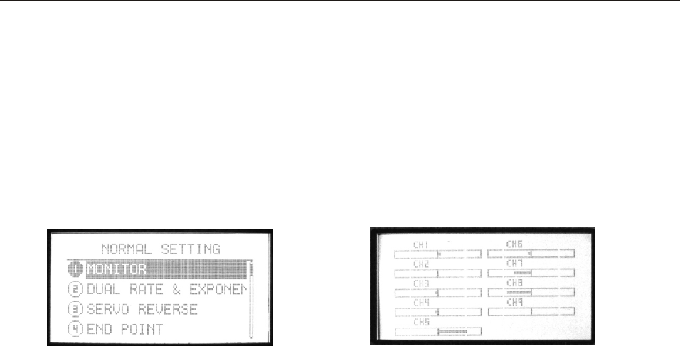
NORMAL SETTING(AIRPLANE)
1. MONITOR
Monitor shows the servos’ movement situation.
In PCMS, this function is to describe the 9 channels output.
In PPM, this function is to describe the first 8 channels output.
Setting Method:
Press menu button, enter system setting, the first function is
the monitor.
INSTRUCTION
AIRPLANE
86
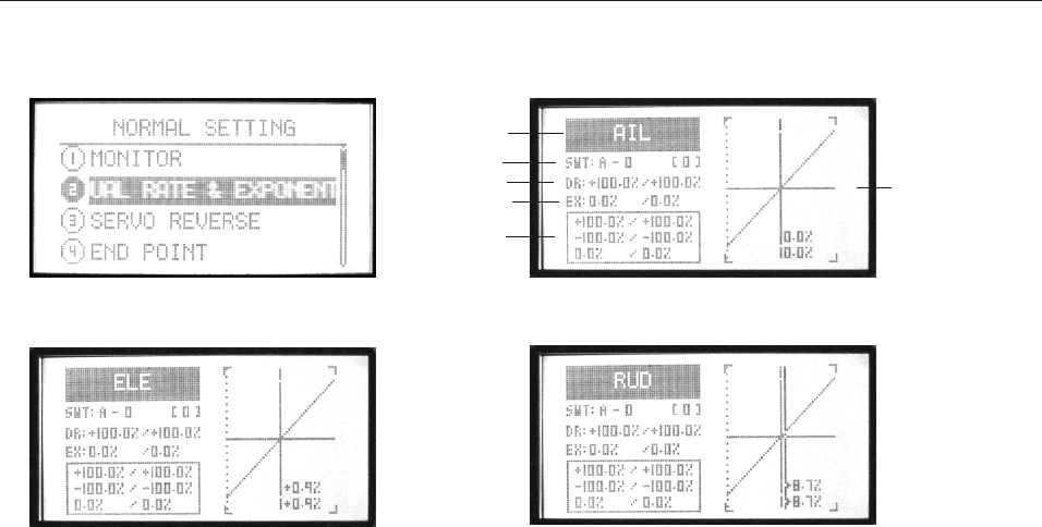
2. DUAL RATE & EXPONENTIAL SETTING
(1). AIL
(2). ELE (3). RUD
Dual rate is to adjust aileron, elevator and rudder travel range.
The range is between 0%-120%.
Exponential setting is to adjust aileron, elevator and rudder
sensitivity when the sticks are around the middle. The range is
between -100% to +100%.
Setting Method:
1. Select channel
Aileron, elevator and rudder are selectable. Press +/- buttons
to select channel, OK button to finish setting.
2. Set the switch and its position(0,1,2)
Press direction button to select “SWT”, edit it. +/- buttons can
select function switch(A-F).
After selecting the function switch, press right direction button
to enter the switch position setting, use +/- buttons to set.
3. Set dual rate
Press direction button to select “D/R”, edit it. Edit one or two
parameter.
+/- buttons can increase or decrease the value.
Press the OK button is to back default.
4. Set exponential
Press direction button to select “EX”. Exponential can adjust
aileron, throttle and rudder sensitivity as the stick at the middle.
5. Set curve point (normal/advanced)
The box under “EX” shows the curve points.
Select “Curve setting” in More setting function list.
Please refer to Page 27 for detail curve setting.
6. Press EXIT after all the values are finished setting.
Servo
Switch
Dual rate
Exponential
Curve point
Curve picture
(please refer to Page 27)
INSTRUCTION
AIRPLANE
87
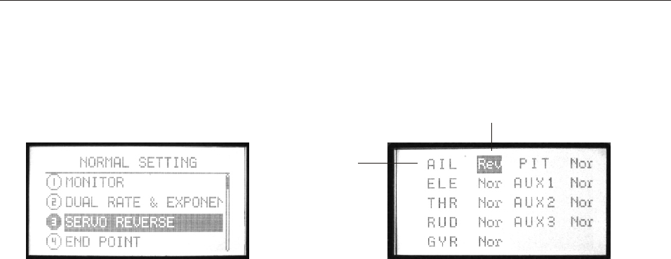
3. SERVO REVERSE
This function is to change the direction of the servos movement.
Setting Method:
Use up/down button to select SERVO REVERSE, OK button is to
enter editing.
Steps:
1. Use direction buttons to select editing part.
2. Use +/- button or OK button to switch the servo movement
direction.
3. Press EXIT after setting.
Direction (Rev-reverse, Nor-normal)
Channel
INSTRUCTION
AIRPLANE
88
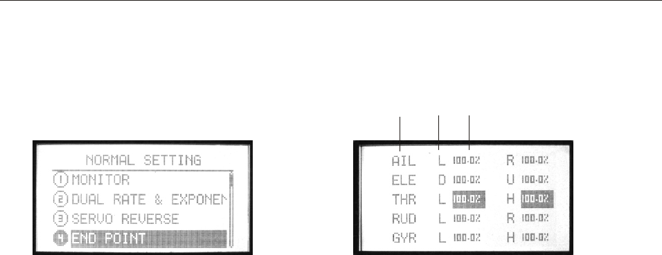
4. END POINT
It is to adjust the end of individual servo’s travel. The range is
from 0% to 120%.
Setting Method:
Use up or down button to select END POINT, OK button is to
enter editing.
Steps:
1. Use direction buttons to select editing part.
2. Use +/- button or OK button to set the travel value. Press
OK for a while backs to default.
3. Press EXIT after setting.
Channel Side Value
INSTRUCTION
AIRPLANE
89
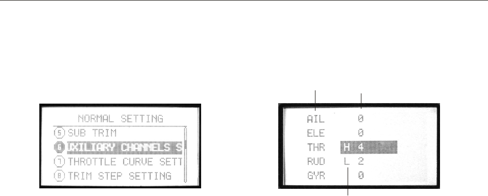
5. SUB TRIM
Sub trim makes small changes or corrections to the neutral
position of each servo. Range is -120 to +120, default setting
is 0.
Setting Method:
Use up or down button to select SUB TRIM, OK button is to
enter editing.
Steps:
1. Use direction buttons to select editing part.
2. Use +/- button or OK button to set the trim value. Press OK
for a while backs to default.
3. Press EXIT after setting.
We recommend that you center the digital trims before making
Sub trim changes, and that you tryto keep all of the Sub trim
values as small as possible. Otherwise, when the Sub trims
are large values, the servo’s range of travel is restricted on
one side.
Channel Value
High/Low
INSTRUCTION
AIRPLANE
90
INSTRUCTION
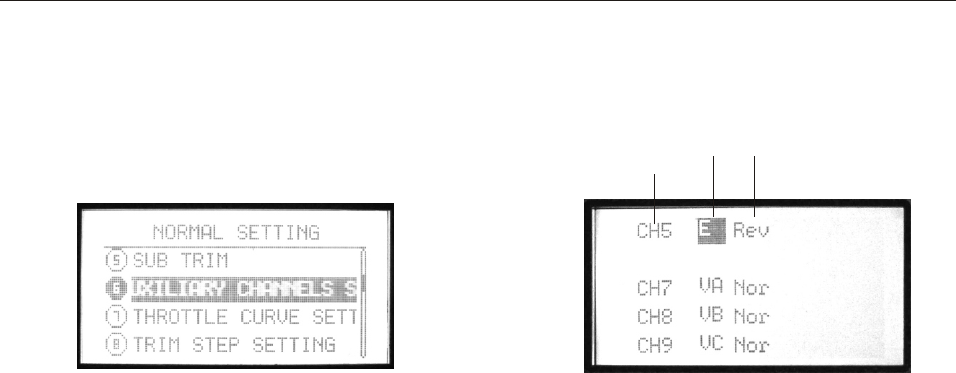
6. AUXILIARY CHANNELS SETTING
This function is for channel 5 to channel 9 function setting.
Setting Method:
Use up or down button to select AUXILIARY CHANNELS
SETTING, OK button is to enter editing.
Steps:
1. Use direction buttons to select editing part.
2. Use +/- button to set the switches or knobs. The switches can
be set from A to F, the knobs can be set as VA, VB, VC, VL,
VR or none(-).
3. Use left or right direction button to set normal or reverse
direction of every channel.
4. Press EXIT after setting.
Channel Switch Direction
AIRPLANE
91
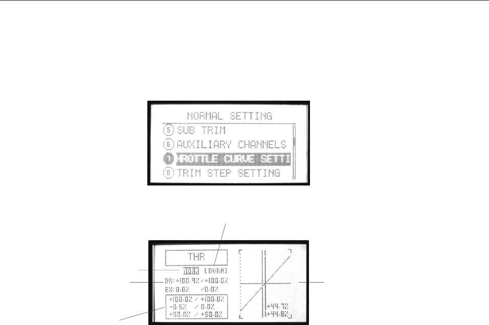
7. THROTTLE CURVE SETTING
Throttle curve, together with the throttle stick, can be adjusted
properly to maximize engine performance at a particular pitch
setting.
There are two kinds of curve setting, normal (7 points curve),
advanced (2-10 points curve), the range is between 0%-120%.
The transmitter can set the following curves:
NORM, IDLE1, IDLE2, IDLE3.
Normal curve is based on hovering, to maximize engine per-
formance at a particular pitch setting.
Idle curve is for engine proper work in a 3D flight, with a good
match between throttle and pitch.
Flight mode
Dual rate
Curve point
Curve picture
(Please refer to Page 27)
Current flight mode
INSTRUCTION
AIRPLANE
92

Setting Method:
Use up/down button to select THROTTLE CURVE SETTING,
OK button is to enter editing.
Steps:
1. Flight(NORM IDLE1 IDLE2 IDLE3)
Use direction buttons to select editing part. Use +/- button to
select one curve.
2. Set Dual rate
Use direction button to select “D/R” and edit (one or two values
can be set separately
or together). Press +/- button for seconds can increase or delete
the value. Press OK button for seconds is to back default(60%).
3. Curve point setting(Normal/Advanced)
The below pane shows the points curve.
Select “Curve setting” in “SYS setting”, choose the curve.
For detail curve setting method please refer to Page 27.
4. Press EXIT after setting.
INSTRUCTION
AIRPLANE
93
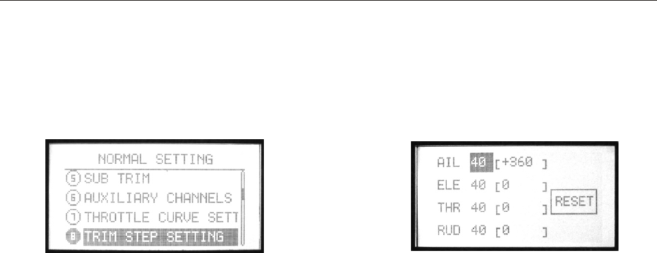
8. TRIM STEP SETTING
This function is to change the rate at which the trim moves
when the TRIM LEVER is activated. The range is from 1 to
250. Generally larger trim steps are for models with larger
control throws or for first flights to ensure sufficient trim to
properly correct the model. Smaller trim steps are later used
to allow very fine adjustments in flight.
Setting Method:
Use up/down button to select TRIM STEP SETTING, OK button
is to enter editing.
Steps:
1. Use direction buttons to select editing part.
2. Use +/- button to adjust the size of the step. Repeat as desired
for other channels. If you select RESET, the current channel trim
value change to 0.
3. Press EXIT after setting.
INSTRUCTION
AIRPLANE
94
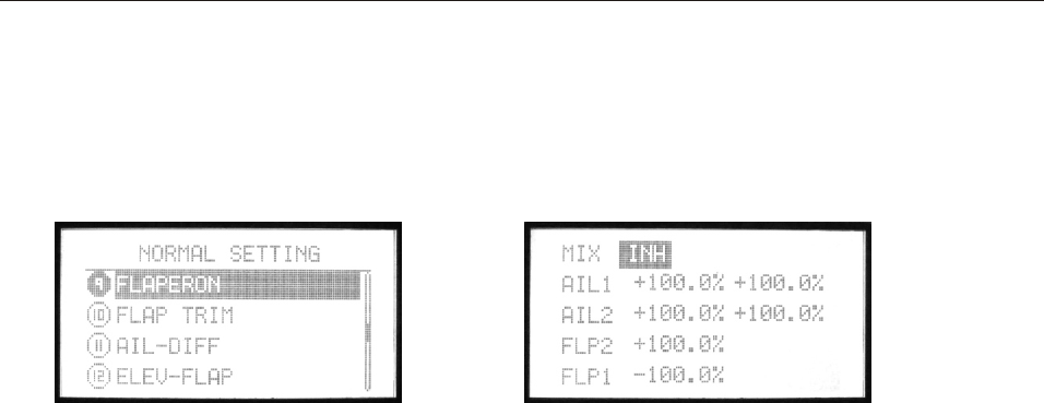
9. FLAPERON
FLAPERON mixing function uses on servo on each of the two
ailerons, and uses them for both aileron and flap function.
INSTRUCTION
Setting Method:
Use up/down button to select FLAPERON, OK button
is to enter editing.
Steps:
1. Use direction buttons to select editing part.
2. Use +/- button to set value. Press OK button for seconds can
back default.
3. Press EXIT after setting.
AIRPLANE
95
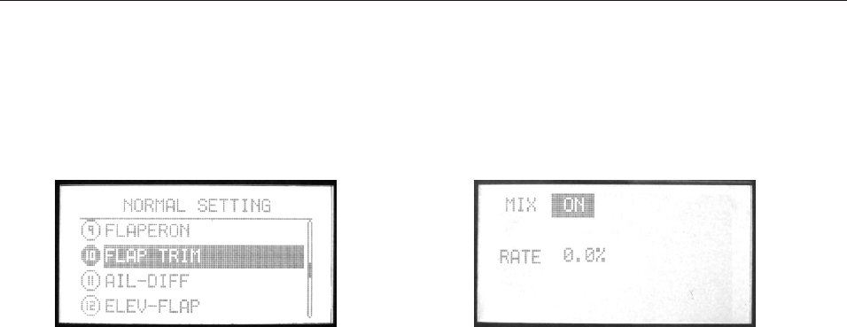
10. FLAP TRIM
FLAP TRIM assigns the primary flaperon control to allow
trimming in flight of the flap action of flaperons.
INSTRUCTION
Setting Method:
Use up/down button to select FLAP TRIM, OK button
is to enter editing.
Steps:
1. Use direction buttons to select editing part.
2. Use +/- button to set value. Press OK button for seconds can
back default.
3. Press EXIT after setting.
AIRPLANE
96
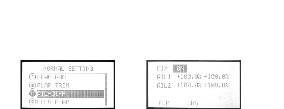
11. AIL-DIFF
Aileron differential(AIL-DIFF) is primarily used on 3-servo
wings, with one servo operating inboard flap(s) on Ch6, and
AIL-DIFF controlling proper aileron operation of 2 aileron
servos, plugged into Ch1 and Ch7.
INSTRUCTION
Setting Method:
Use up/down button to select AIL-DIFF, OK button
is to enter editing.
Steps:
1. Use direction buttons to select editing part.
2. Use +/- button to set value. Press OK button for seconds can
back default.
3. Press EXIT after setting.
AIRPLANE
97
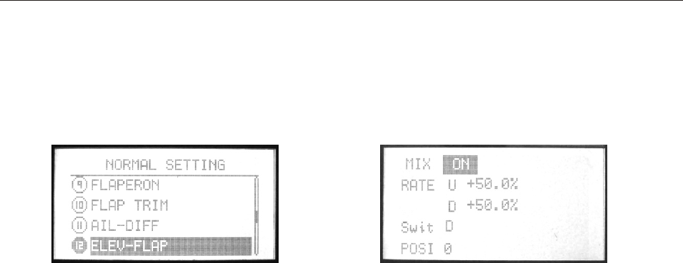
12. ELEV-FLAP
ELEV-FLAP mixing is the first pre-programmed mix we’ll cover.
This mix makes the flaps drop or rise whenever the elevator
stick is moved. It is most commonly used to make tighter pylon
turns or squarer corners in maneuvers. In most cases, the flaps
droop (are lowered) when up elevator is commanded.
INSTRUCTION
Setting Method:
Use up/down button to select ELEV-FLAP, OK button
is to enter editing.
Steps:
1. Use direction buttons to select editing part.
2. Use +/- button to set value. Press OK button for seconds can
back default.
3. Press EXIT after setting.
AIRPLANE
98
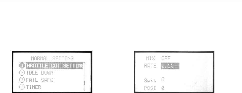
13. THROTTLE CUT SETTING
This function is to shut off the engine at the end of a flight. The
engine can be stopped with one touch of any switch, eliminating
the need to move the trim to kill the engine and then readjust prior
to each flight. The helicopter THR CUT includes an ON/OFF
throttle position (normally a little above idle). You must move the
THROTTLE STICK back below the set point before the THR-CUT
function can be reset, to avoid sudden engine acceleration.
Setting Method:
Use up/down button to select THROTTLE CUT SETTING,
OK button is to enter editing.
Steps:
1. Use direction buttons to select editing part.
2. Use +/- button to turn on/off throttle cut function.
3. Use +/- button to set the throttle rate and trim (range is between
+45% to -45%).
4. Use +/- button to set the position.
5. Press EXIT after setting.
INSTRUCTION
AIRPLANE
99
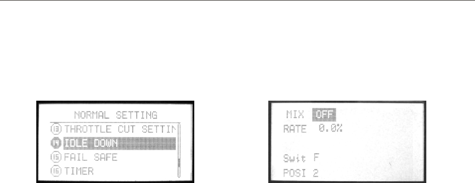
14. IDLE DOWN
This function is to lowers the engine idle for: sitting on the run-
way prior to take off, stalls and spins, and landings. The normal
idle setting is a little higher for easier starts and safe flights with
less risk of dead sticks.
The idle down function is not normally used when starting the
engine, and its accidental operation may keep your engine from
starting.
Setting Method:
Use up/down button to select IDLE DOWN, OK button is to
enter editing.
Steps:
1. Use direction buttons to select editing part.
2. Use +/- button to set value. Press OK button for seconds can
back default.
3. Press EXIT after setting.
INSTRUCTION
AIRPLANE
100
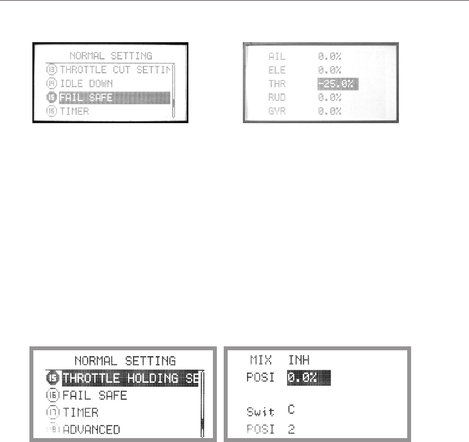
This function is to set responses in case of loss of signal or low RX
battery.
Setting Method:
Use up/down button to select FAIL SAFE, OK button is to enter
editing.
Steps:
1. Use direction buttons to select editing part.
2. Use +/- button to select “hold” or “0.0%”
3. Press OK button to confirm the current parameter.
4. Press EXIT after setting.
15. FAIL SAFE
INSTRUCTION
AIRPLANE
16. THROTTLE HOLDING SETTING
Description
throttle hold setting allows the user fix the throttle at the low value when
landing. Throttle hold setting value can be adjusted between +/-100%.
Setting
Enter Normal setting menu, use up or down button to select throttle hold
setting. Press OK button to enter value setting.
Value setting method
1, use direction button to highlight the item and enter value edit mode
2, use +/- to set the MIX value as "ON/OFF" or "Inhibit".
3, use +/- to set the value under "Position" option. Press and hold OK
button to reset to default value.
4, under switch option, Use +/- to choose the switch to active this function
5, use +/- to set the on/off position of the switch. press and hold Ok button
can back to default setting.
6, press exit button to quit after
101
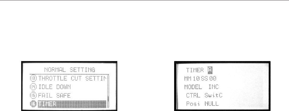
17. TIMER
The flight time of every helicopter is different according to
the different tank of fuel, engine, ESC, etc. Timer function
can alarm you to land before the fuel lacks.
The transmitter can set 3 timers (A, B, C). The longest time
can be set as MM99SS59. The countdown timer can alarm
user before 10 minutes. The alarm will become 2S/1S from
1S/1S in the last 10 seconds. When the countdown timer is
0, the time will add up.
The timer can be seen in the opening screen. Any switch
can be set to control the begin and stop of the time.
Setting Method:
Use up/down button to select TIMER, OK button is to enter
editing.
Steps:
1. Use direction buttons to select editing part.
2. Set timer. WFT09S can set 3 timers (A, B, C).
3. Use +/- button to set MM..SS... Press OK button for seconds
can back to default.
4. Use +/- button to set model.
5. Use +/- button to set control(CTRL).
6. Use +/- button to set the position which can active this
function.
7. Press EXIT after setting.
INSTRUCTION
AIRPLANE
102
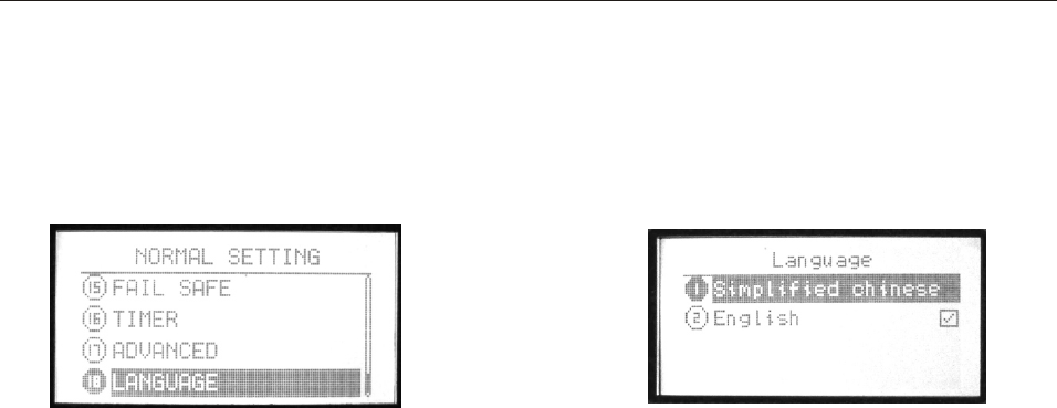
19. Language
This function is to select the language, Simplified Chinese and
English can be selected.
INSTRUCTION
AIRPLANE
103
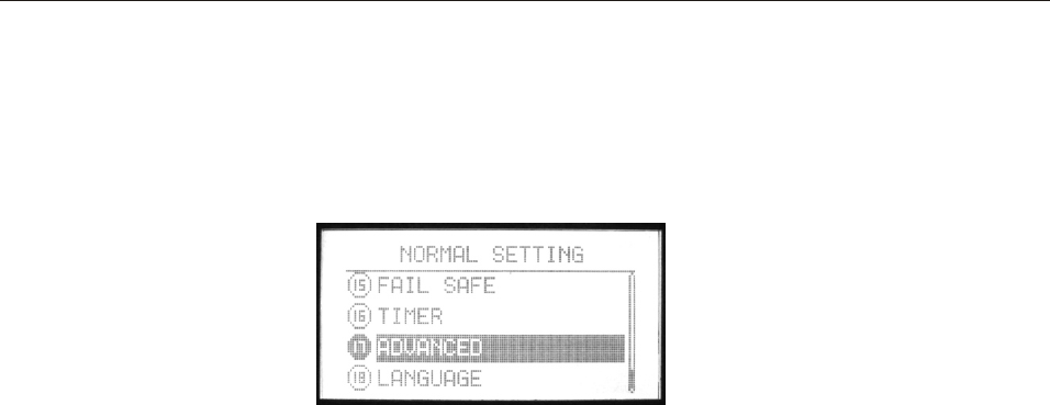
18. ADVANCED
To realize an idea fly, there are 20 advanced function in
ADVANCED.
Setting Method:
Use up/down button to select ADVANCED, OK button is to enter
editing. +/- button can turn page.
About each advanced functions please read the following pages.
INSTRUCTION
AIRPLANE
104
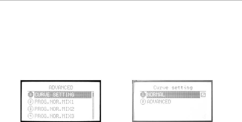
ADVANCED function introduction
INSTRUCTION
(1). CURVE SETTING
There are 2 kinds of setting, Normal and Advanced.
Please refer to page 27.
AIRPLANE
105
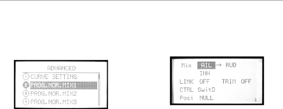
(2)-(8). PROG. NOR. MIX1-7
The mix program is to adjust the flying pose. There are 7series
programs with the same setting method. You can set one mix
and one mix with another one mix.
Setting Method
Use up/down button to select PROG. NOR. MIX, OK button is
to enter editing.
Steps:
1. Use direction buttons to select editing part. Set any two
channels mix.
2. Use +/- button to active or inhibit “Mix”.
3. Use +/- button to active or inhibit “Link” and “TRIM”.
4. Use +/- button to active or inhibit “CTRL“.
5. Use +/- button to set the control switch position.
6. Press EXIT after setting.
INSTRUCTION
AIRPLANE
106
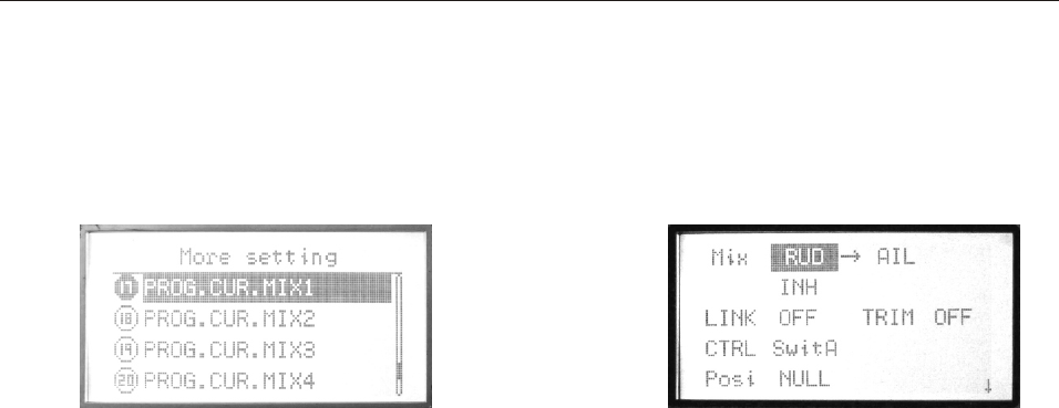
(9)-(12). PROG. CUR. MIX1-4
There are 4 curve mix program, the curve is made up by
2 to 10 point.
Setting Method:
Use up/down button to select PROG. CUR. MIX, OK button
is to enter editing.
Steps:
1. Use direction buttons to select editing part. Set any two
channels mix.
2. Use +/- button to active or inhibit “Mix”.
3. Use +/- button to active or inhibit “Link” and “TRIM”.
4. Use +/- button to active or inhibit “CTRL“.
5. Use +/- button to set the control switch position.
6. Set the curve point.(Normal/Advanced). Please refer to
page 27.
7. Press EXIT after setting.
INSTRUCTION
AIRPLANE
107
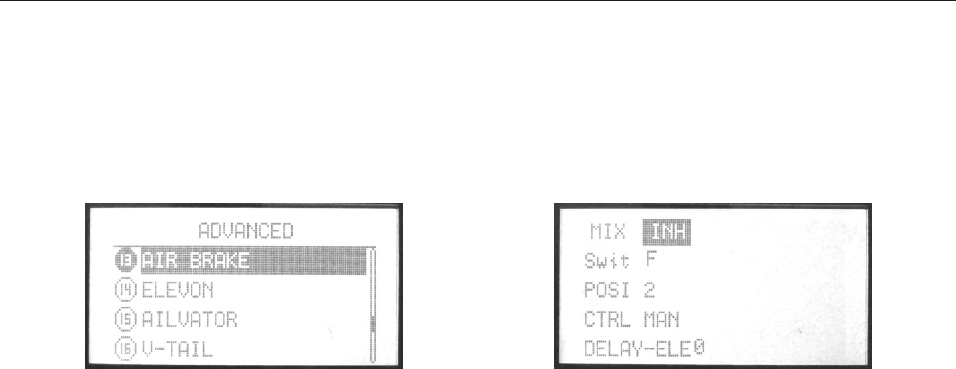
(13). AIR BRAKE
AIR BRAKE simultaneously moves the flaps, twin ailerons
and elevators, and is usually used to make steep descents or
to limit increases in airspeed in dives.
Setting Method:
Use up/down button to select AIR BRAKE, OK button
is to enter editing.
Steps:
1. Use direction buttons to select editing part.
2. Use +/- button to active or inhibit “Mix”.
3. Use +/- button to set Swit, POSI. Press OK button for seconds
can back default.
4. Use +/- button to set CTRL (MAN/ THR).
5. Use +/- button to set delay value. Press OK button for seconds
can back default.
6. Press EXIT after setting.
INSTRUCTION
AIRPLANE
108
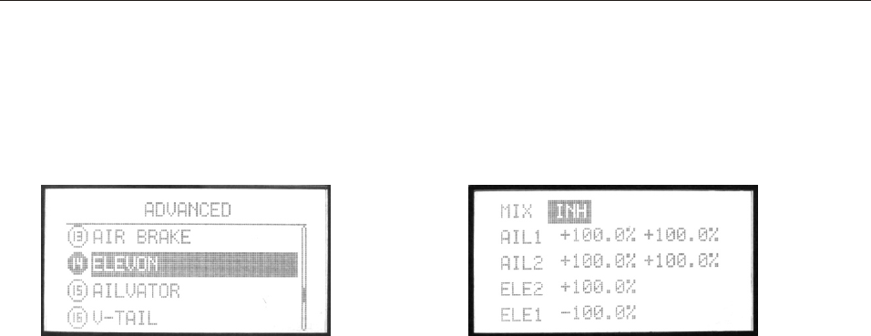
(14). ELEVON
This function used with delta wings, flying wings, and other
tailless aircraft that combine aileron and elevator functions,
using two servos, one on each elevon. The aileron/elevator
responses of each servo can be adjusted independently.
Setting Method:
Use up/down button to select ELEVON, OK button is to
enter editing.
Steps:
1. Use direction buttons to select editing part.
2. Use +/- button to set value. Press OK button for seconds can
back default.
3. Press EXIT after setting.
INSTRUCTION
AIRPLANE
109
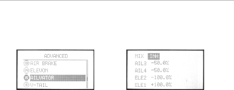
(15). AILVATOR
AILEVATOR mixing function uses one servo on each of the
two elevators, and combines the elevator function with the
aileron function(unless aileron travel is set to 0).
Setting Method:
Use up/down button to select AILVATOR, OK button is to
enter editing.
Steps:
1. Use direction buttons to select editing part.
2. Use +/- button to set value. Press OK button for seconds can
back default.
3. Press EXIT after setting.
INSTRUCTION
AIRPLANE
110
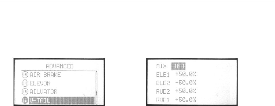
(16). V-TAIL
V-TAIL mixing is used with v-tail aircraft so that both elevator
and rudder functions are combined for the two tail surfaces.
Both elevator and rudder travel can be adjusted independently
on each surface.
Setting Method:
Use up/down button to select V-TAIL, OK button is to
enter editing.
Steps:
1. Use direction buttons to select editing part.
2. Use +/- button to set value. Press OK button for seconds can
back default.
3. Press EXIT after setting.
INSTRUCTION
AIRPLANE
111
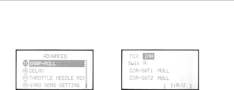
(17). SNAP-ROLL
This function allows you to execute snap rolls by flipping a
switch, providing the same input every time. It also removes
the need to change dual rates on the 3 channels prior to
performing a snap, as snap-roll always takes the servos to the
same position, regardless of dual rates, inputs held during
the snap, etc.
Setting Method:
Use up/down button to select SNAP-ROLL, OK button is to
enter editing.
Steps:
1. Use direction buttons to select editing part.
2. Use +/- button to set value. Press OK button for seconds can
back default.
3. Press EXIT after setting.
INSTRUCTION
AIRPLANE
112
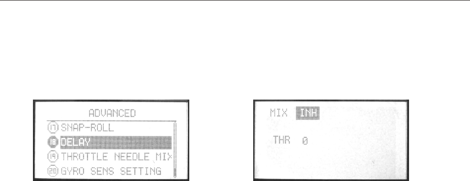
(18). DELAY
DELAY function is used to slow the response of the throttle
servo to simulate the slow response of a turbine engine.
Setting Method:
Use up/down button to select DELAY, OK button is to enter
editing.
Steps:
1. Use direction buttons to select editing part.
2. Use +/- button to active or inhibit this function. Press OK
button for seconds can back default.
3. Press EXIT after setting.
INSTRUCTION
AIRPLANE
113
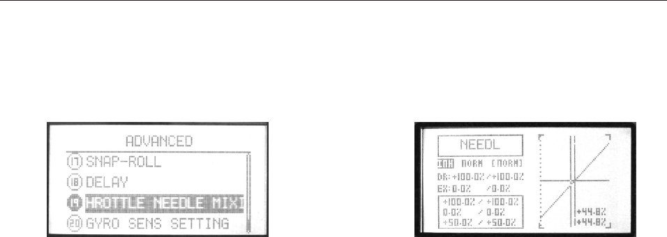
(19). THROTTLE NEEDLE MIXING
Throttle needle is a pre-programmed mix that automatically
moves an in-flight mixture servo in response to the Throttle
Stick imputs for perfect engine tuning at all throttle settings.
This function is particularly popular with contest pilots who fly
in a large variety of locations, needing regular engine tuning
adjustments, and requiring perfect engine response at all times
and in all maneuvers. Also popular to minimize flooding at idle
of inverted engine installations or installations with a high tank
position. Not need for fuel injection engine, which do this
automatically.
Setting Method
Use up/down button to select Throttle needle mixing, OK
button is to enter editing.
Steps:
1. Use +/- button to active or inhibit this function.
2. Use +/- button to select one curve. There’re 3 curves,
NORM, IDLE1, IDLE2, IDLE3.
3. Use direction button to select “D/R”
Edit one or two parameter.
+/- buttons can increase or decrease the value.
Press the OK button is to back default.
4. Use direction button to select “EX”
Edit one or two parameter.
+/- buttons can increase or decrease the value.
Press the OK button is to back default.
EX can adjust aileron, throttle, rudder sensitivity when the
sticks are around the middle.
There are a lot of mixes when “D/R” and “EX” come together.
5. Curve setting method please refer to page 27.
INSTRUCTION
AIRPLANE
114
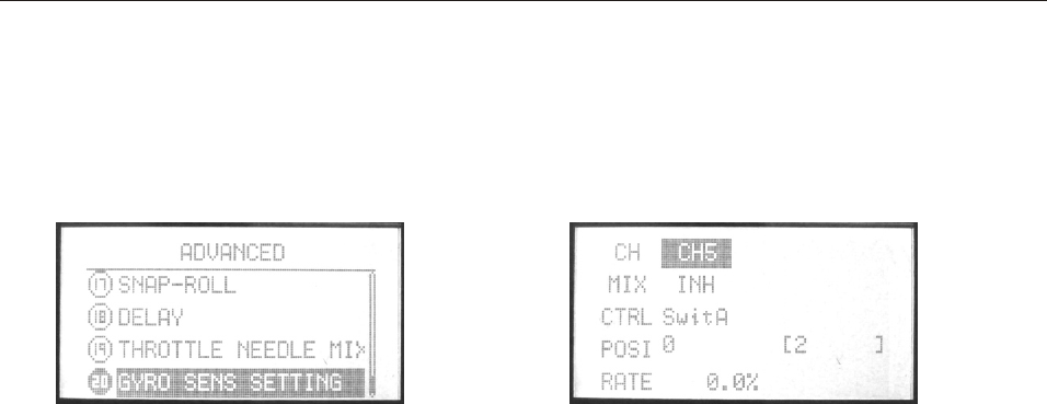
(20). GYRO SENS SETTING
User can adjust the gyro sensitivity by transmitter,
AVCS gyro (GY) and normal gyro (STD).
Gyro sensitivity switch plug should plug in the fifth channel
of receiver. The auxiliary channel CH 5 won’t have any
function now. User can set sensitivity switch from switch A to F,
and also fly model (NORM, IDLE1,2,3).
Setting Method:
Use up/down button to select GYRO sens setting, OK button
is to enter editing.
Steps:
1. Use direction buttons to select editing part.
2. Use +/- button to set fly model at “MODE”.
3. Use +/- button to active or inhibit “Mix”. Press OK button
for seconds can back
default.
4. Use +/- button to set control switch at “CTRL”.
5. Use +/- button to set the switch position when the function
is active.
6. Use +/- button to set the “Rate”. Press OK button for seconds
can back default.
7. Press EXIT after setting.
INSTRUCTION
AIRPLANE
(21). Code matching
Please refer to page 16.
115
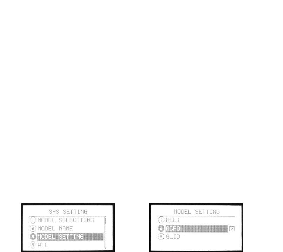
GLIDER
Press Menu and turn on the transmitter to enter SYS SETTING.
Select MODEL SETTING, press OK button to select the model
type.
Restart the transmitter after setting.
INSTRUCTION
GLIDER
116
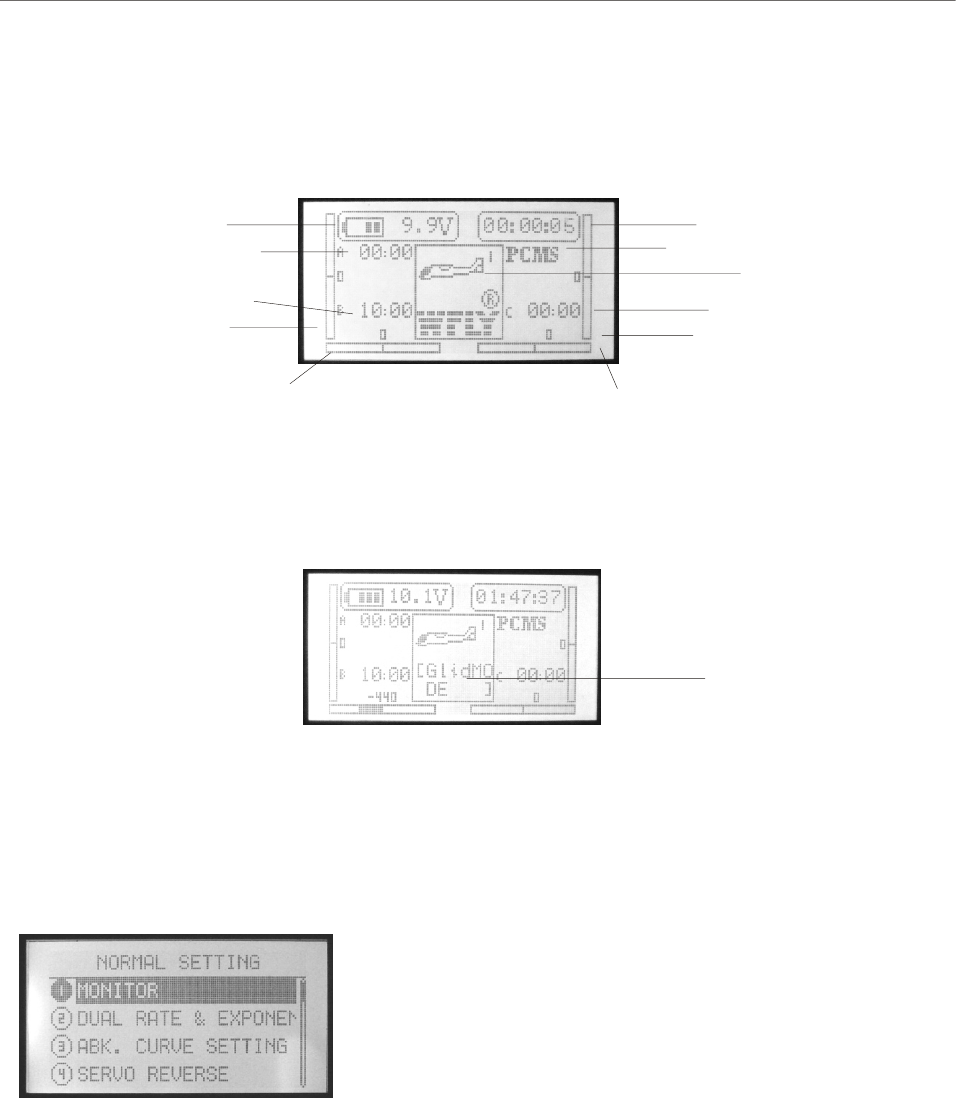
1. Opening Screen
The opening screen displays the voltage, timer, model, aileron,
throttle, elevator and rudder state.
2. Menu Screen
There are “NORMAL SETTING”, “SYS SETTING”, “ADVANCED”.
Turn on the power switch, the LCD displays as follows.
A. NORMAL SETTING
Turn on the transmitter, press the menu button, the LCD displays
as follows.
1. MONITOR
2. DUAL RATE & EXPONENTIAL SETTING
3. ABK. CURVE SETTING
4. SERVO REVERSE
5. END POINT
6. SUB TRIM
7. AUXILIARY CHANNELS SETTING
8. TRIM STEP SETTING
9. FLAPERON
10. FLAP TRIM
11. AIL-DIFF
12. ELEV-FLAP
13. FAIL SAFE
14. TIMER
15. ADVANCED
16. LANGUAGE
Voltage Start time
Timer A
Timer B Timer C
Model type
Throttle trim
display
Rudder trim display Aileron trim display
Elevator trim display
Modulation
Editing mode and function introduction
Note: Press EXIT you can see the model name.
Setting method:
1. Use direction button to select the
editing part,use up/down buttons to
select function item. Left/right
direction button to turn page.
2. Press OK button to enter submenu.
The submenu function is in the next
chapter.
3. Press EXIT button to back previous
menu and the data is set automatically.
Model name
INSTRUCTION
GLIDER
117
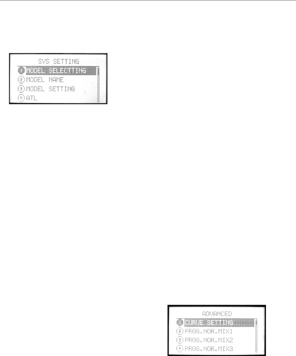
B. SYS SETTING
Press Menu and turn on the power switch, the LCD displays as
follows.
1. MODEL SELECTING
2. MODEL NAME
3. MODEL SETTING
4. ATL
5. AIL-2
6. MODULATION SETTING
7. STICK SETTING
8. ADJUSTMENT
9. REST SETTING
10. SEND DATA
11. RECEIVE DATA
12. SOUND
13. CONTRAST SETTING
14. ENGINEER MODE
15. ABOUT
16. LANGUAGE
Setting method:
1. Use direction button to select the
editing part,use up/down buttons to
select function item. Left/right direction
button to turn page.
2. Press OK button to enter submenu.
The submenu function is in the next
chapter.
3. Press EXIT button to back previous
menu and the data is set automatically.
C. ADVANCED
1. Enter “NORMAL SETTING”, use right direction button to turn page,
select “ADVANCED”.
Press OK button to enter.
Setting method:
1. Use direction button to select the editing part,
use up/down buttons to select function item.
Left/right direction button to turn page.
2. Press OK button to enter submenu. The submenu
function is in the next chapter.
3. Press EXIT button to back previous menu and the
data is set automatically.
INSTRUCTION
GLIDER
118
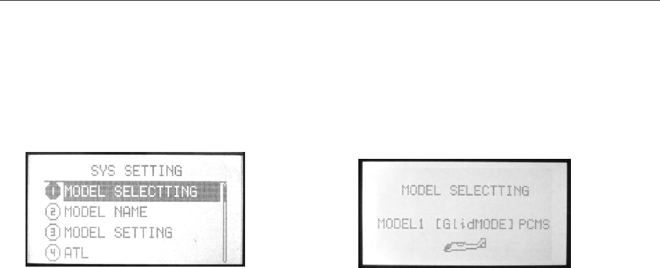
1.MODEL SELECTTING
There are 85 glider models. You can select any one to set.
Setting Method:
Press Menu and turn on the transmitter to enter “SYS SETTING”
Use up/down button to select “MODEL SELECTING”, OK button is
to enter editing.
Steps:
1. Use up/down direction button to select the model.
2. Press OK button to select.
3. Press EXIT after setting.
SYS SETTING
INSTRUCTION
GLIDER
119
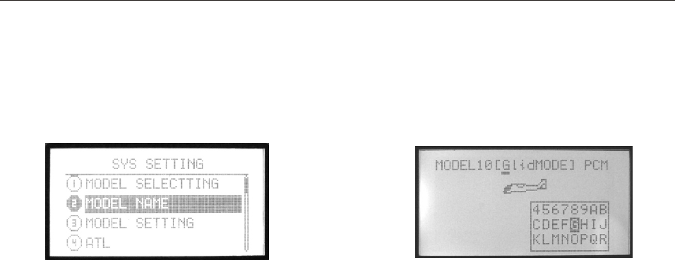
2. MODEL NAME
This function is to make new names by users.
Setting Method:
Press Menu and turn on the transmitter to enter “SYS SETTING”
Use up/down button to select “MODEL NAME”, OK button is to
enter editing.
Steps:
1. You can edit the underlined letter.
2. Press OK button to choose the word you like.
3. Press EXIT after setting.
INSTRUCTION
GLIDER
120
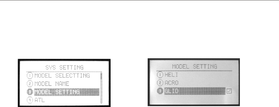
3. MODEL SETTING
You can select the model type. There are three type: HELI,
ACRO, GLID.
Setting Method:
Press Menu and turn on the transmitter to enter “SYS SETTING”
Use up/down button to select “MODEL SETTING”, OK button is
to enter editing.
Steps:
1. Use up/down direction button to select the model type.
2. Press OK button to confirm.
3. Press EXIT after setting.
INSTRUCTION
GLIDER
121
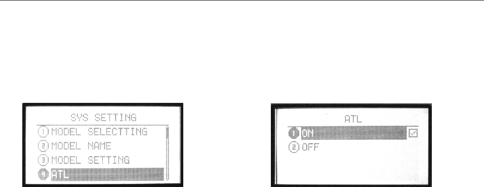
Adjustable travel limit (ATL) makes throttle trim effective only at
low throttle, disabling the trim at high throttle. This prevents
pushrod jamming due to idling trim changes. This function defaults
to ON. If you are not using channel 3 for throttle, you may want trim
operation the same as on all other channels. To do so, set ATL to
OFF.
Setting Method:
Press Menu and turn on the transmitter to enter “SYS SETTING”
Use up/down button to select “ATL”, OK button is to enter editing.
Steps:
1. Use direction buttons to select the editing part.
2. Press +/- button to set ATL function.
3. Press EXIT after setting.
4. ATL
INSTRUCTION
GLIDER
122
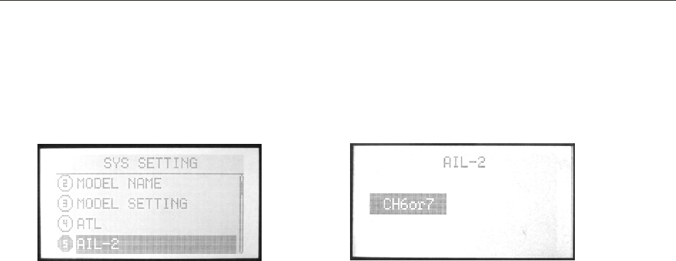
AIL-2 is another channel for aileron.
Setting Method:
Press Menu and turn on the transmitter to enter “SYS SETTING”
Use up/down button to select “AIL-2”, OK button
is to enter editing.
Steps:
1. Use direction buttons to select.
2. Press OK button to confirm.
3. Press EXIT after setting.
5. AIL-2
INSTRUCTION
GLIDER
123
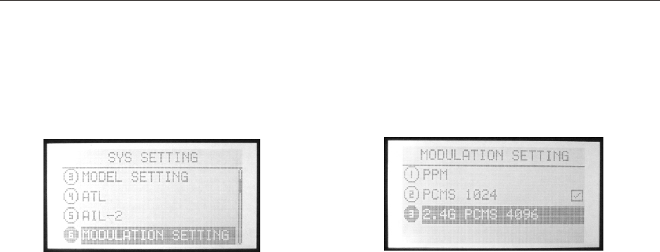
6. MODULATION SETTING
Because of the different receiver modulation PPM/PCMS1024,
/2.4G PCMS4096the transmitter should be accordance with the
receiver modulation.
Setting Method:
Press Menu and turn on the transmitter to enter “SYS SETTING”
Use up/down button to select “Modulation setting”, OK button
is to enter editing.
Steps:
1. Use direction buttons to select the editing part.
2. Press OK button to confirm. Restart the transmitter and it
works.
INSTRUCTION
GLIDER
7.RF setting
Please refer to page 27.
124
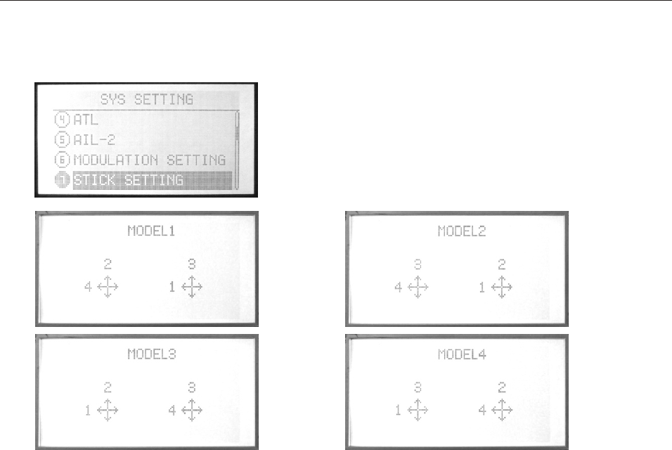
8.STICK SETTING
There are 4 kinds of model, you can use up/down direction
button to select the model you preferred.
Setting Method:
Press Menu and turn on the transmitter to enter “SYS SETTING”
Use up/down button to select “STICK SETTING”, OK button is
to enter editing.
Steps:
1. Use direction button to select the editing part.
2. Press up/down button to choose Stick mode.
3. Press EXIT after setting.
1-aileron
2-elevator
3-throttle
4-rudder
INSTRUCTION
GLIDER
125

This function is to set the central, high and low point of four sticks
when users changed the mode I or II by themselves.
Setting Method:
Press Menu and turn on the transmitter to enter “SYS SETTING”
Use up/down button to select “ADJUSTMENT”, OK button is
to enter editing.
Steps:
1. Use direction button to select the editing part. Take the aileron
adjustment for example.
2. Make the stick in the mid-point location. Press OK button
to select any stick you want to adjust.
3. Select into the Figure 2, when the "center" highlights, press the "ok"
button directly (the mid-point has been adjusted), then enter the high
adjust.
4.The "high” highlights, take the stick gently in the right side
(throttle /elevator in the top, aileron / rudder in the right),press "ok"
button ( the max adjust is OK), enter the low adjustment.
5.The "low" highlights, take the stick gently in the left side (throttle
/elevator in the bottom, aileron / rudder in the left),press "ok" button
(the min adjust is OK).
6. Press OK or RESET to confirm the record or reset.
7. If the record is wrong, press OK will back to step 3.
9.Adjustment
INSTRUCTION
GLIDER
126
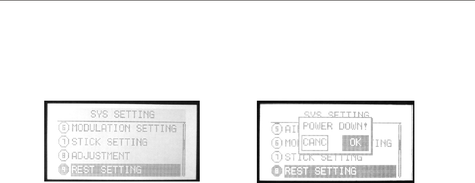
This function is to back default.
Setting Method:
Press Menu and turn on the transmitter to enter “SYS SETTING”
Use up/down button to select “RESET SETTING”, OK button is
to enter editing.
Steps:
1. Use direction button to select the editing part.
2. Press +/- button to back default.
3. Press EXIT after setting.
10.RESET SETTING
INSTRUCTION
GLIDER
127
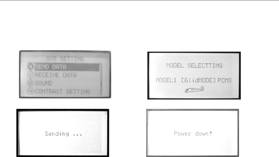
11. SEND DATA
Two transmitters (WFT09S) can copy data by a trainer cable/data
transfer cable. This function together with the next function
“Receive data” can realize the data copy.
Setting Method:
Press Menu and turn on the transmitter to enter “SYS SETTING”
Use up/down button to select “SEND DATA”, OK button is
to enter editing.
Steps:
1. Select the model data you want to send out.
2. Press OK to send.
INSTRUCTION
GLIDER
128
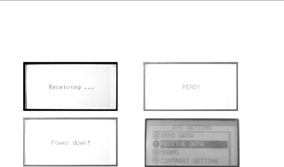
12.RECEIVE DATA
Two transmitters (WFT09S) can copy data by a trainer cable/data
transfer cable. This function together with the previous function
“Send data” can realize the data copy.
Setting Method:
Press Menu and turn on the transmitter to enter “SYS SETTING”
Use up/down button to select “RECEIVE DATA”, OK button is
to enter editing.
Steps:
1. Press OK to receive data.
2. Restart the transmitter after receiving the data and it works.
INSTRUCTION
GLIDER
129

This function is to select the sound ON and OFF.
Setting Method:
Press Menu and turn on the transmitter to enter “SYS SETTING”
Use up/down button to select “SOUND”, OK button is
to enter editing.
Steps:
1. Use +/- button to select ON and OFF.
2. Press OK button to confirm.
3. Press EXIT after setting.
13.Sound
INSTRUCTION
GLIDER
130