Shyam Telecom BTSLINK-208 BTS Link-208 Repeater User Manual 1
Shyam Telecom Inc. BTS Link-208 Repeater 1
Contents
- 1. User Manual 1
- 2. User Manual 2
User Manual 1
All Rights Reserved Shyam Telecom Limited Page
1 / 40
Next Generation
Signal Enhancement
OPTICAL / MOU Series / BTS LINK
O
OP
PE
ER
RA
AT
TI
IO
ON
N
&
&
I
IN
NS
ST
TA
AL
LL
LA
AT
TI
IO
ON
N
M
MA
AN
NU
UA
AL
L
B
BT
TS
S
L
Li
in
nk
k
®
®
-
-2
20
08
8
Contents
5920 0020 200 A
p
ril 2008
Proprietary Information
The information contained herein is proprietary to Shyam Telecom Limited.
Unauthorized access, copy, and replication are prohibited. This document must
not be copied in whole or part by any means or it shall not be disclosed o
r
divulged to any third Party without the prior written consent of Shyam Telecom
Limited.
F
FI
IB
BE
ER
R
O
OP
PT
TI
IC
CA
AL
L
D
DI
IS
ST
TR
RI
IB
BU
UT
TE
ED
D
A
A
N
NT
TE
EN
NN
N
A
A
S
SY
YS
ST
TE
EM
Mw
wi
it
th
h8
8D
DB
BR
RO
OU
Us
s
MOU DBROU

All Rights Reserved Shyam Telecom Limited Page
2 / 40
Next Generation
Signal Enhancement
1. DOCUMENT HISTORY......................................................................................2
2. DISCLAIMER......................................................................................................3
3. SAFETY INSTRUCTIONS AND WARNINGS ...................................................4
3.1. PERSONNEL SAFETY .....................................................................................4
3.2. EQUIPMENT SAFETY......................................................................................4
3.3. ELECTROSTATIC SENSITIVITY ........................................................................5
4. INTRODUCTION ................................................................................................5
4.1. PURPOSE .....................................................................................................5
4.2. SCOPE .........................................................................................................6
4.3. DEFINITIONS .................................................................................................6
4.4. REFERENCES ...............................................................................................6
4.5. GENERAL .....................................................................................................7
5. FUNCTIONAL DESCRIPTION OF BTS LINK-208 REPEATER.......................7
5.1. GENERAL DESCRIPTION ................................................................................7
5.2. INDOOR/OUTDOOR COVERAGE ......................................................................9
6. TO GET STARTED-BASIC SOFTWARE CONTROL OF THE SYSTEM.......11
6.1. GENERAL ...................................................................................................11
6.2. TERMINAL SET-UP.......................................................................................11
6.3. BLOCK DESCRIPTION ..................................................................................21
7. BTS LINK-208 REPEATER SPECIFICATIONS.............................................24
7.1. ELECTRICAL SPECIFICATIONS-RF & OPTICAL...............................................24
7.2. ELECTRICAL SPECIFICATION POWER REQUIREMENT .....................................24
7.3. EXTERNAL ELECTRICAL/OPTICAL INTERFACE...............................................24
7.4. MECHANICAL SPECIFICATION.......................................................................24
7.5. ENVIRONMENTAL SPECIFICATION .................................................................25
7.6. CONTENTS OF DELIVERY .............................................................................25
7.7. SAFETY PRECAUTIONS-HANDLING OPTICAL EQUIPMENT ...............................25
8. INSTALLATION................................................................................................26
8.1. PREPARATION SHEET-PRE INSTALLATION.....................................................26
8.2. MOU INSTALLATION....................................................................................27
8.3. OPTICAL FIBER CABLE LAYING ....................................................................29
8.4. INSTALLATION-DBROU...............................................................................30
8.5. DOS & DON’T DOS......................................................................................31
8.6. CHECKLIST-POST INSTALLATION ..................................................................32
9. SYSTEM MAINTENANCE ...............................................................................34
9.1. GENERAL ...................................................................................................34
9.2. PREVENTATIVE MAINTENANCE.....................................................................34
1. Document History
Document
Number Document
Name Date Compiled
by Approved
by Revision
5920 0020 200 BTS Link- 208
Ap
ril Inderjit D.S.Nagi

All Rights Reserved Shyam Telecom Limited Page
3 / 40
Next Generation
Signal Enhancement
Repeater 2008
Revision Revised Section Date
Intentionally Left Blank
2. Disclaimer
Every attempt has been made to make this material complete, accurate,
and up-to-date. Users are cautioned, however, that Shyam Telecom
Limited reserves the right to make changes without notice and shall not be
responsible for any damages including consequential, caused by reliance of

All Rights Reserved Shyam Telecom Limited Page
4 / 40
Next Generation
Signal Enhancement
the contents presented, including, but not limited to, typographical,
arithmetical, or listing errors.
Product name(s) referenced in this document may be trademarks or
registered trademarks of their respective companies, and are hereby
acknowledged.
In areas with unstable power grids (mains) all repeaters must be installed
with a voltage regulator ensuring a constant voltage level at the repeater
power input. A maximum voltage deviation should remain within the input
range to the repeaters for warranty purposes.
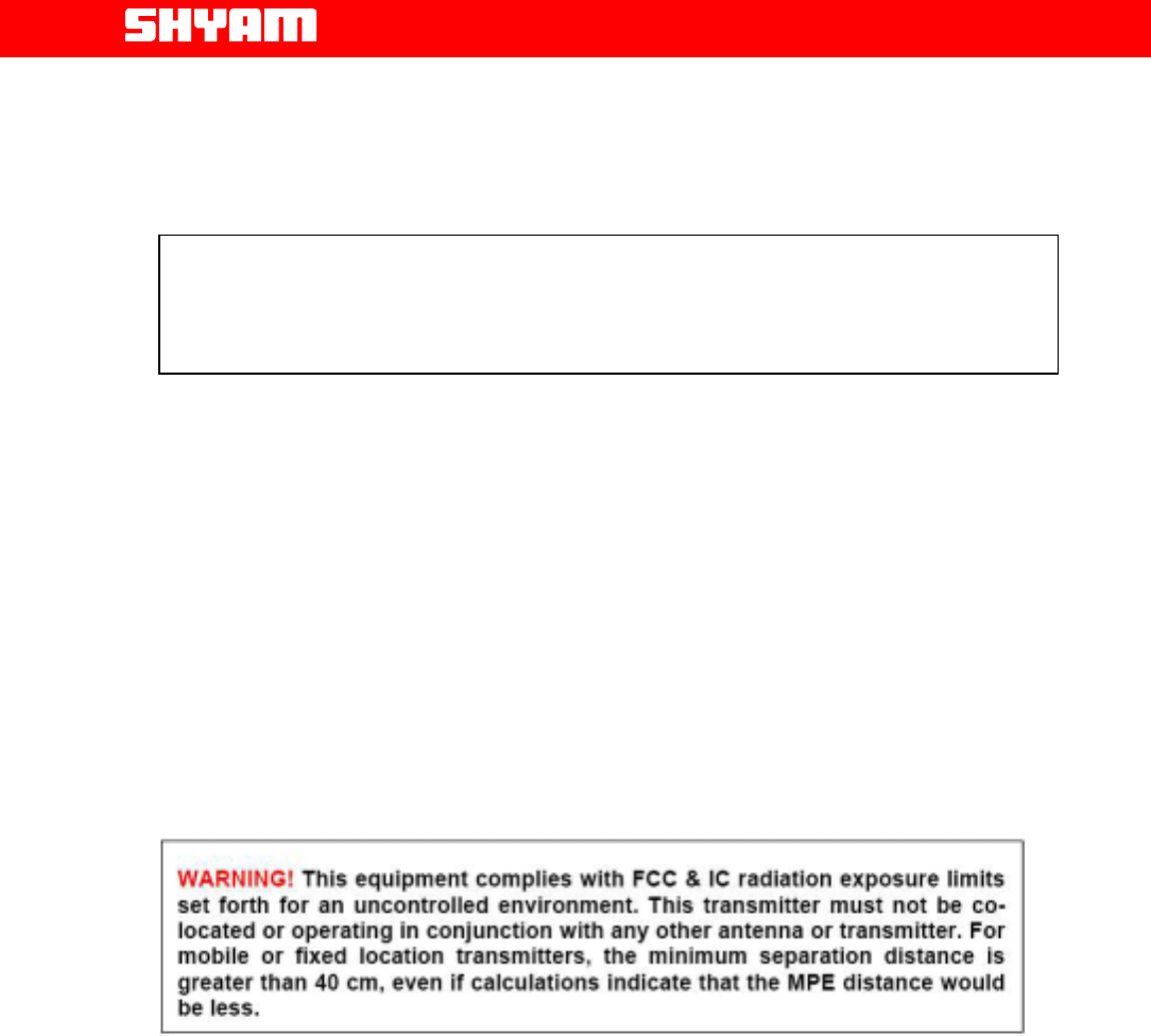
All antennas must be installed with lighting protection. Damage to internal
modules, as a result of lightning is not covered by the warranty.
All specifications are subject to change without prior notice
3. Safety Instructions and Warnings
3.1. Personnel Safety
Before installing or replacing any equipment, the entire manual should be
read and understood. The user needs to supply the appropriate AC power
to the Repeater. Incorrect AC power settings can damage the repeater and
may cause injury to the user.
Throughout this manual, there are "Caution" warnings, "Caution" calls
attention to a procedure or practice, which, if ignored, may result in injury
or damage to the system or system component or even the user. Do not
perform any procedure preceded by a "Caution" until the described
conditions are fully understood and met.
3.2. Equipment Safety
When installing, replacing or using this product, observe all safety
precautions during handling and operation. Failure to comply with the
following general safety precautions and with specific precautions described
elsewhere in this manual violates the safety standards of the design,
manufacture, and intended use of this product. Shyam Telecom Limited
assumes no liability for the customer's failure to comply with these
precautions. This entire manual should be read and understood before
operating or maintaining the repeater system.
CAUTION
It calls attention to a procedure or practice which, if not followed, may result
in personal injury, damage to the system or damage to individual
components. Do not perform any procedure preceded by a
All Rights Reserved Shyam Telecom Limited Page
5 / 40
Next Generation
Signal Enhancement
CAUTION until described conditions are fully understood and met.
3.3. Electrostatic Sensitivity
CAUTION
ESD = ELECTROSTATIC DISCHARGE SENSITIVE DEVICE
Observe electrostatic precautionary procedures.
Semiconductor transmitters and receivers provide highly reliable
performance when operated in conformity with the intentions of their design.
However, a semiconductor may be damaged by an electrostatic charge
inadvertently imposed by careless handling.
Static electricity can be conducted to the semiconductor chip from the
centre pin of the RF input connector, and through the AC connector pins.
When unpacking and otherwise handling the Repeater, follow ESD
precautionary procedures including the use of grounded wrist straps,
grounded workbench surfaces, and grounded floor mats.
4. Introduction
4.1. Purpose
The purpose of this document is to describe the electrical and mechanical
specifications, operation and maintenance of the BTS Link-208 Repeater.

All Rights Reserved Shyam Telecom Limited Page
6 / 40
Next Generation
Signal Enhancement
4.2. Scope
This document is the product description of the Shyam BTS Link-208
Repeater.
4.3. Definitions
AGC Automatic Gain Control
ALC Automatic Level Control
APC Automatic Power Control
BTS Base Transceiver Station
CDMA Coded Division Multiple Access
CMC Configuration & Monitoring Console software
DBROU Dual Band Remote Optical Unit
DCS Digital Communication System
DL Downlink signal (from base station via repeater to
mobile station)
EGSM Extended Global System for Mobile Communication
ETSI European Telecommunications Standard Institute
FDF Fiber Distribution Frame
GSM Global System for Mobile communication
IMD Inter Modulation Distortion
LAC Location Area Code of the BTS site
LED Light Emitting Diode
LNA Low Noise Amplifier
LO Local Oscillator
MOU Master Optical Unit
MS Mobile Station
NMS Network Management System
PCN Personal Communication Network
PCS Personal Communication System
PSU Power Supply Unit
RF Radio Frequency
RMS Remote Management System
ROU Remote Optical Unit
RSSI Received Signal Strength Indication
UL (Uplink) Uplink signal direction (from mobile station via
repeater to base station)
UMTS Universal Mobile Telecommunication System
4.4. References
[1] ETS 300 086.
Radio Equipment and Systems Land mobile service Technical
characteristics and test conditions for radio equipment with an internal or
external RF connector intended primarily for analogue speech.

All Rights Reserved Shyam Telecom Limited Page
7 / 40
Next Generation
Signal Enhancement
[2]ETS300609-4.
Digital cellular telecommunications system (phase 2): Base Station
Systems (BSS) equipment specification: Part 4: Repeaters.
[3] ETS 300 342-3
Radio Equipment and Systems (RES); Electro-Magnetic Compatibility
(EMC) for European Digital Cellular Telecommunications systems. Base
Station Radio and ancillary equipment and Repeaters meeting phase 2
GSM requirements.
4.5. General
Mobile Communications Systems are planned as cellular systems and each
cell of the base station is required to provide RF coverage over a certain
geographical area as per defined RF power levels. Due to the RF
propagation properties, even using high radiated RF powers or complicated
antenna systems, there are zones within the coverage area where the RF
signal strength from base station remains inadequate for establishing the
desired connectivity to mobile users.
Repeaters traditionally are deployed in the Mobile Communication Network
to fill in the “Dead Zones” caused by blocking of signals by geographic
topologies such as mountains, valleys, dense foliage, high rise urban
landscapes, and other man-made structures. The distance from the base
station also adversely affects the RF signal strength. The user views
repeaters as a means to extend base station coverage so as to reduce the
number of base stations and thereby accelerate network availability.
Repeater systems are installed after meticulous planning between BTSs
and the mobile users to provide RF coverage in the shadowed regions.
Repeater systems are available for different applications and ultimate
choice shall depend on some of the factors mentioned below:
• Area to be provided with coverage.
• Indoor/outdoor coverage.
• Availability of BTSs in the vicinity.
5. Functional Description of BTS Link-208 Repeater
5.1. General Description
The BTS Link-208 Repeater System is designed to provide indoor
coverage and can handle signals in two service bands viz. Cellular & PCS,
used by various service operators. It provides highly selective amplification
in the pre-set bands. The details of operating frequencies are:

All Rights Reserved Shyam Telecom Limited Page
8 / 40
Next Generation
Signal Enhancement
Cellular 869 MHz to 894 MHz (DL) 824 MHz to 849 MHz (UL)
PCS 1930 MHz to 1990 MHz (DL) 1850 MHz to1910 MHz (UL)
• The BTS Link-208 repeater system is a dual band Distributed
Antenna System (DAS) for point to point & point to multi-point
coverage.
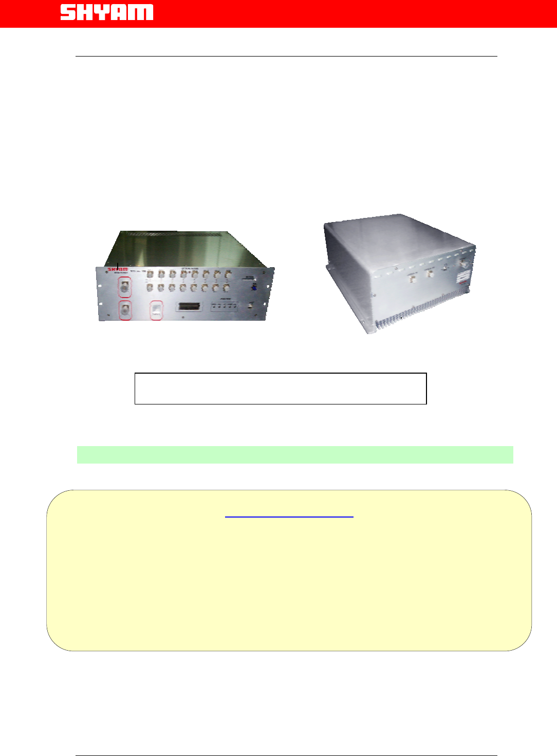
• It is comprised of a Master Optical Unit (MOU) and Dual Band
Remote Optical Units (DBROUs), maximum 8, installed at different
sites. MOU & DBROUs are connected through a pair of optical
fibers.
• DBROUs with appropriate housings for indoor application can be
installed at the pre-planned sites.
• Master Optical Unit (MOU) is installed at indoor location close to
BTSs from where the signals are to be received and also OFC
terminations destined for DBROUs at different sites are available.
• The repeater is deployed in the network where RF coverage is
required for large clusters of mobile users at different sites.
• The repeater can be equipped with a RMS (Optional) for speedy
maintenance & monitoring.
• The antenna isolation problem is of little consequence since the
signals between MOU and DBROUs are propagated as optical
signals, which are insensitive to any electrical
interference/disturbances.
The system is comprised of two units:
I) Master Optical Unit (MOU): The MOU is installed at a suitable indoor
location close to the BTS. It receives/transmits RF signals in dual band
from the BTSs through BTS couplers and optical signals from different
DBROUs. It consists of modules/units:
• Duplexers [Band 1 & Band 2]
• Optical Transmitter Unit (OTX)
• Optical Splitter (1:4)
• Optical Receiver Unit (ORX)
• Power Supply Unit
• Gain modules
• Supervisory and ASK modem
• A metallic housing (Indoor application) accommodates all the
above units/modules. Arrangement is made for dissipation of
heat generated in the unit and the unit is not waterproof.

All Rights Reserved Shyam Telecom Limited Page
9 / 40
Next Generation
Signal Enhancement
II) Dual Band Remote Optical Unit (DBROU): Depending on the
requirement DBROUs maximum up to 4 or 8 are installed at different
locations where coverage is desired. Each of the DBROUs consists of
modules/units:
• Optical Receiver Unit (ORX)
• Power Amplifier
• Quad-plexer
• LNA
• Optical Transmitter Unit (OTX)
• Power Supply Unit
• Gain modules
• Supervisory & ASK module
• A metallic housing for Indoor application accommodates all the
above units/modules. The housing is designed for dissipation of
heat generated in the unit.
5.2. Coverage
When installing DBROU for indoor application, precautions should be taken
not to expose it to direct Sunlight, chemical fumes, and water vapors etc.
Suitable sets of server antennas are to be installed at predetermined
locations to achieve the desired coverage. Some of the applications are
shown in Figures 2 & 3.
All Rights Reserved Shyam Telecom Limited Page
10 / 40
Next Generation
Signal Enhancement
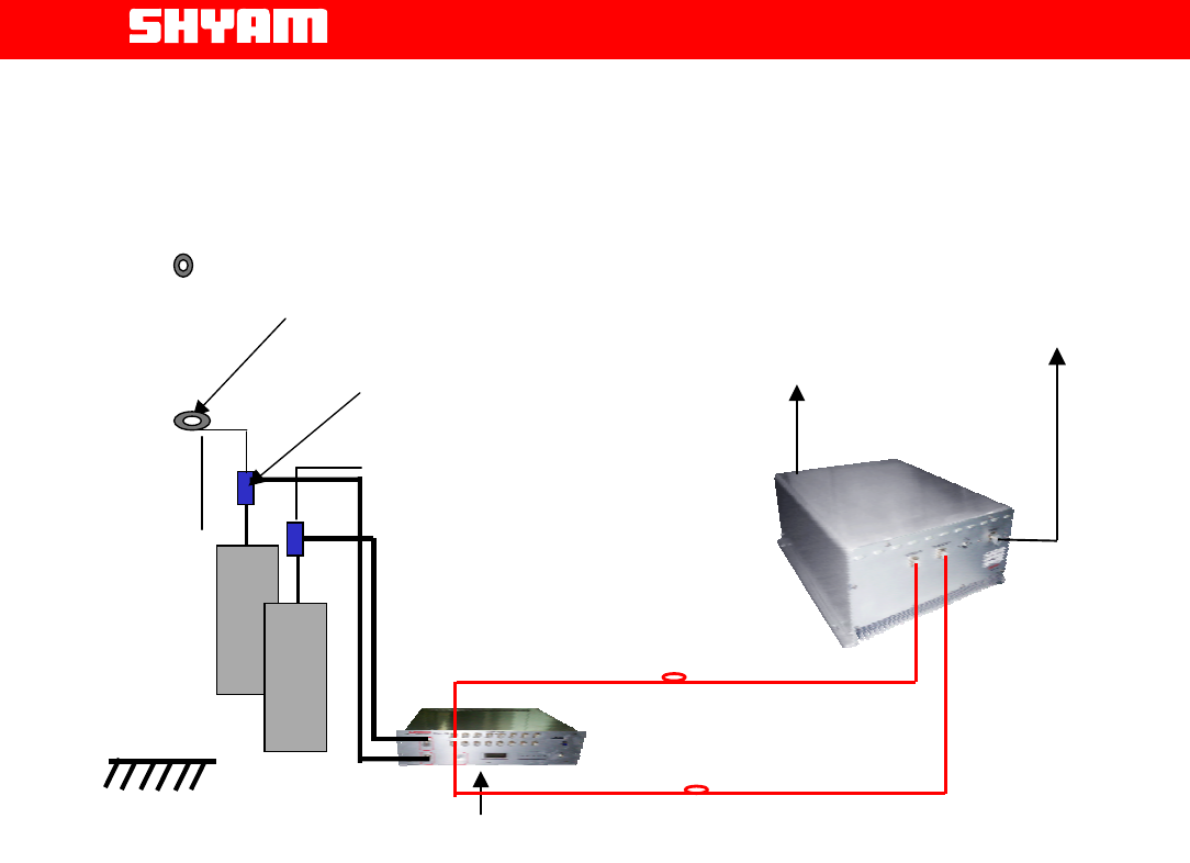
Figure 1: Constituents of BTS Link-208 Repeater
SM Optical
Fiber
B
T
S
Directional Coupler (40dB)
M
OU
In
sta
ll
ed
in
t
h
e
BT
S
En
c
l
osu
r
e
RF Cable Clamp
DBROU
B
T
S
To Relevant
Antenna
To server antenna
To AC Mains
All Rights Reserved Shyam Telecom Limited Page
11 / 40
Next Generation
Signal Enhancement
6. To Get started-Basic Software Control of the System
6.1. General
The system (MOU & DBROU) is equipped with a supervisory module that
allows the monitoring and control of various parameters such as RF power,
attenuation, temperature, and alarm conditions etc.
The communication interface between the local terminal and the control
module can be set up using the Configuration & Monitoring Console
software (CMC), which is an easy to use GUI for simple control and
monitoring. It enables monitoring of parameters & subsequent adjustment if
required.
This function can be performed either using a terminal (PC/laptop) locally,
or through remote login using the wireless modem (Optional) located in the
repeater. USB port is provisioned in the equipment for connecting
PC/laptop.
6.2. Terminal Set-up
The system is delivered with software loaded in order to perform
configuration as per requirement. It also enables monitoring the status.
Configuration of parameters can be carried out locally at MOU & DBROU
with the help of laptop / PC connected to the system by means of local USB
serial interface or remotely via wireless modem (Optional) mounted inside
the MOU. The laptop/PC should be loaded with the CMC software available
on the supplied CD along with the USB driver.
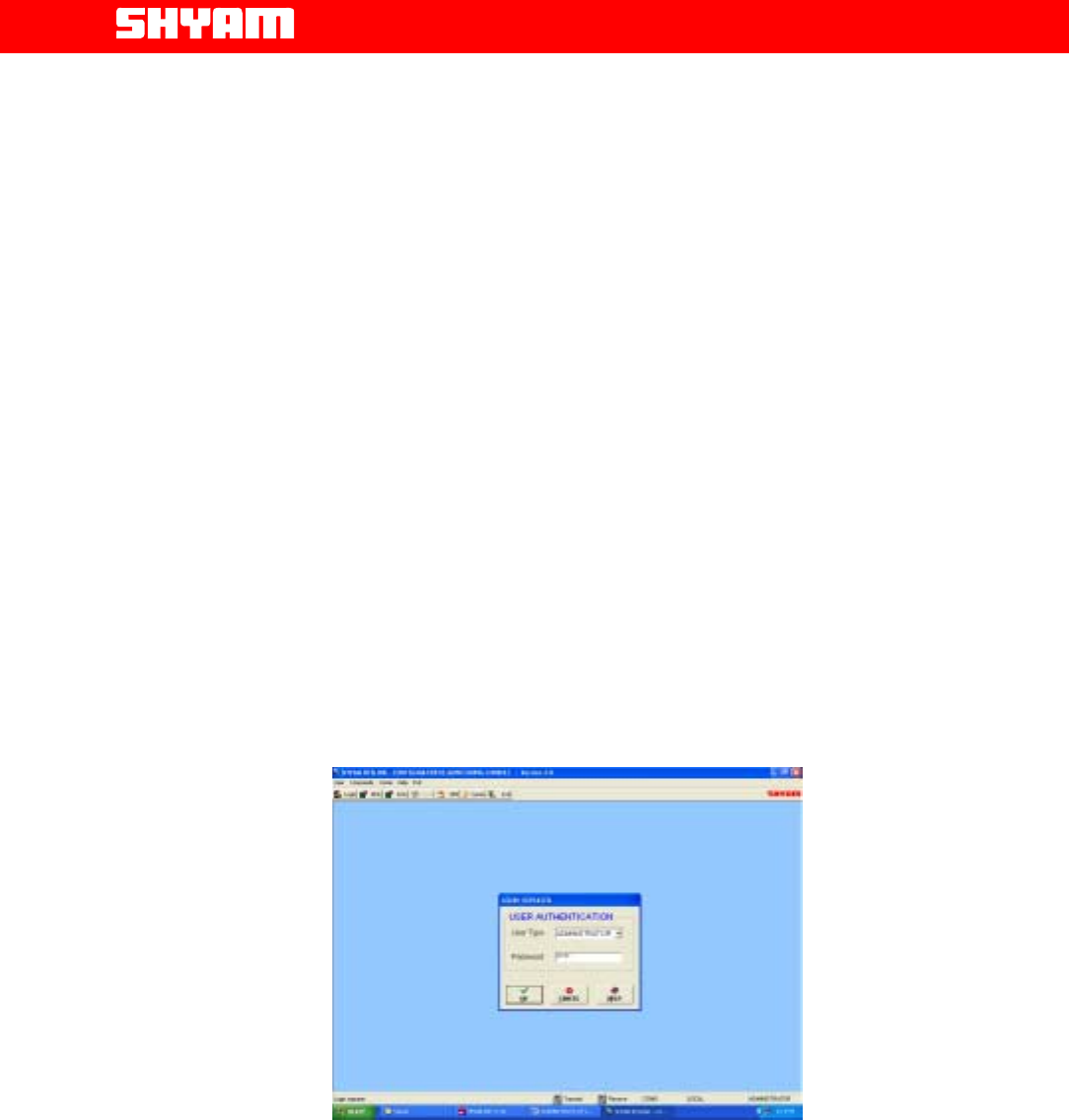
Figure 4: Login Repeater

All Rights Reserved Shyam Telecom Limited Page
12 / 40
Next Generation
Signal Enhancement
Functions as described below are carried out through CMC software:
I) Login Repeater (Figure 4)
After running the Configuration & Monitoring Console (CMC), user
needs to login. Similar sequence is to be followed at MOU & ROU. To
login:
• Click the “Login” on the command bar.
• Select the user type.
• Enter the password.
• Finally click the “OK”.
After successful login a message, “Logged in successfully” message
appears on the screen. Now user can start the operation through CMC.
There are two types of user’s viz. ADMINISTRATOR and
SUPERVISOR. If user logged in as an ADMINISTRATOR, all the
operation through the CMC can be carried out. By default password is
“SHYAM”.
SUPERVISOR is allowed to perform monitoring of the status & alarms
but no change in configuration is permitted. However, the SUPERVISOR
can change password if so desired.
II) Configuration & Monitoring
Configuring system means setting the system parameters for operation
as per the requirement at site. Configuration & monitoring is carried out
at MOU and ROU separately.
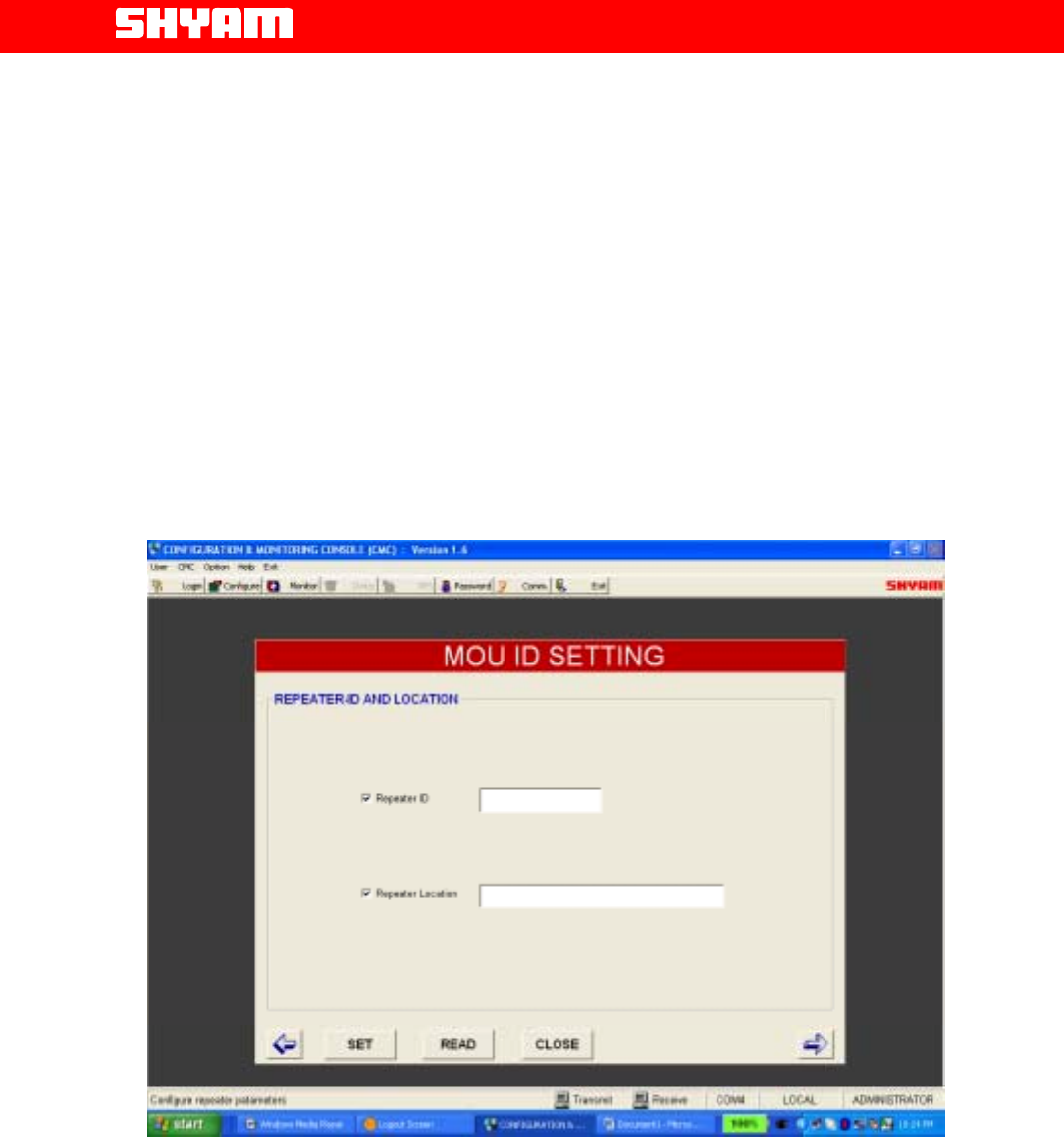
a) Settings in MOU
To begin with MOU ID settings as per Figure 5 are carried out,
information specified is:
• Repeater ID
• Repeater Location
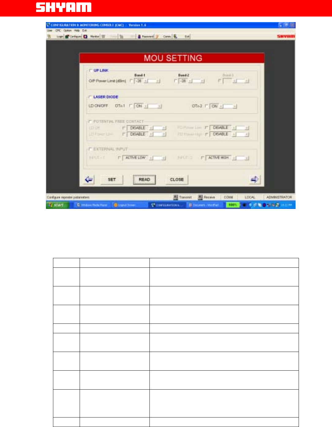
Configurable parameters as per Figure 6 are:
• Out put power limit UL Band 1
• Out put power limit UL Band 2
• Laser Diode ON/OFF
• OTX1 ON/OFF and OTX2 ON/OFF
After specifying these parameters, SET is pressed
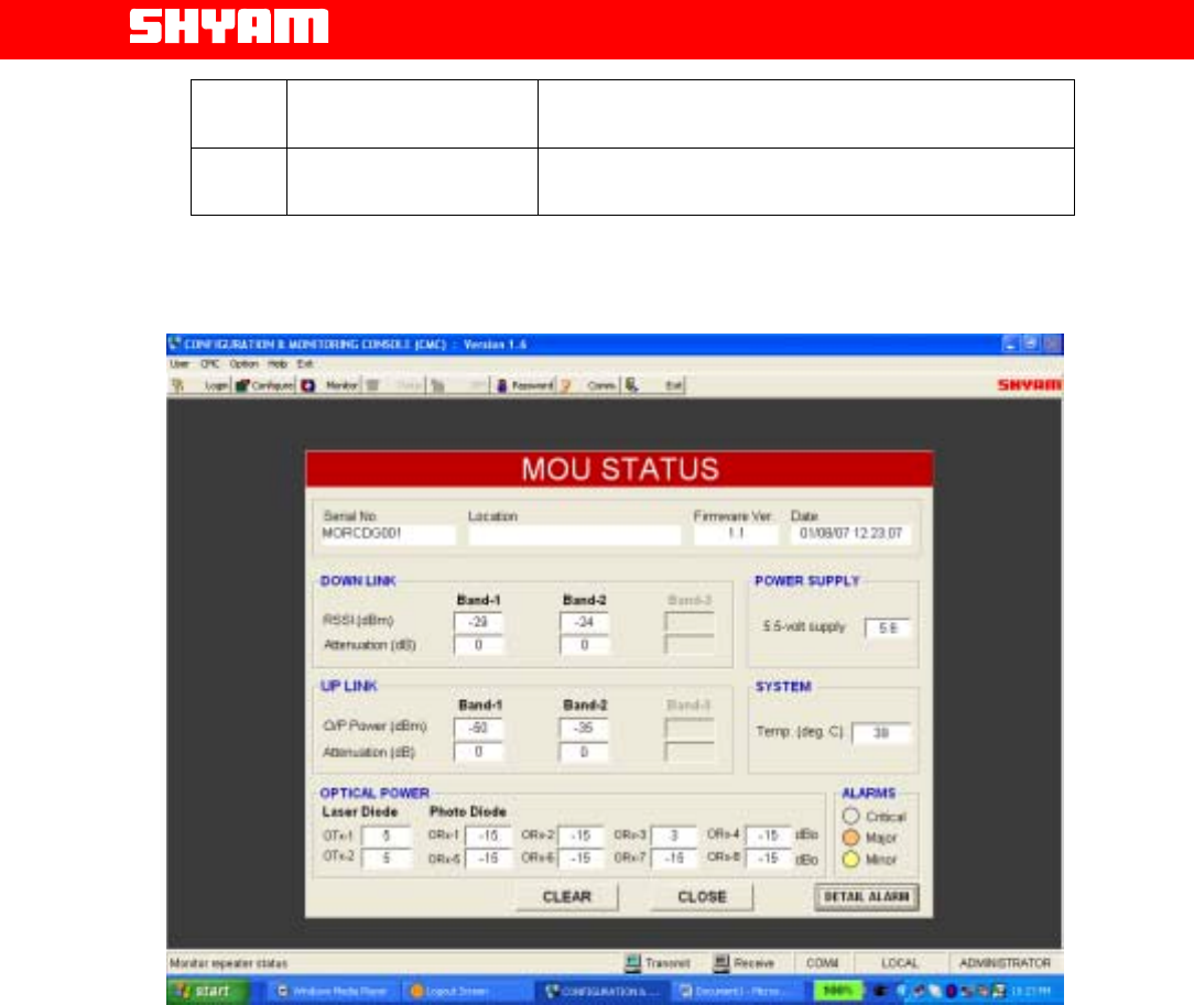
b) MOU Status
Status of MOU as per Figure 7 is displayed through following set
(configurable) parameters:
All Rights Reserved Shyam Telecom Limited Page
13 / 40
Next Generation
Signal Enhancement
Downlink
• RSSI Band 1 & Band 2
• Attenuation in Band 1 & Band 2
Uplink
• Out put Power Band 1 & Band 2
• Attenuation in Band 1 & Band 2
Optical Power
• OTX 1 & OTX 2
• ORX 1 to 8 [As per number of equipped DBROUs]
Power Supply
• 5.5 V
Alarms
• Alarms as per categorization viz. Critical, major & minor are set.
Clicking at “detail alarms” can further check detail of alarms.
Figure 5: MOU ID Settings
All Rights Reserved Shyam Telecom Limited Page
14 / 40
Next Generation
Signal Enhancement
Figure 6: MOU Settings Window
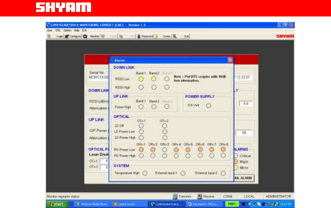
c) MOU-Alarms (Figure 9)
S.NO. Alarm Remarks
1. RSSI Low Down Link The alarm is generated when the RSSI detected is lower than
the set limit in Band 1/Band 2.
2. RSSI High Down Link The alarm is generated when the RSSI detected exceeds the
set limit in Band 1/Band 2.
3. Power High (uplink) The alarm is generated when the power limit detected
exceeds the limit in Band 1/Band 2.
4. Power Supply 5.5 V The alarm indicates the failure/low of 5.5 V power supply.
5. LD OFF The alarm is generated when Laser Diode Off is detected in
OTX 1/OTX 2.
6. LD power low The alarm is generated when lower optical power than the set
is detected from Laser Diode is detected in OTX 1 /OTX 2.
7. LD power high The alarm is generated when higher than the set optical
power from Laser Diode is detected in OTX 1 /OTX 2.
8. PD power low The alarm is generated when lower than the set optical power
from photo diode is detected in ORX 1…..ORX 8 (De[pending
on the number of ROUs equipped)
9. PD power high The alarm is generated when higher than the set optical
All Rights Reserved Shyam Telecom Limited Page
15 / 40
Next Generation
Signal Enhancement
power from photo diode is detected in ORX 1…..ORX 8
(De[pending on the number of ROUs equipped)
10. System Temperature It indicates that the temperature of the system has exceeded
the limit.
Figure 7: MOU Status
All Rights Reserved Shyam Telecom Limited Page
16 / 40
Next Generation
Signal Enhancement
Figure 8: MOU-Alarms
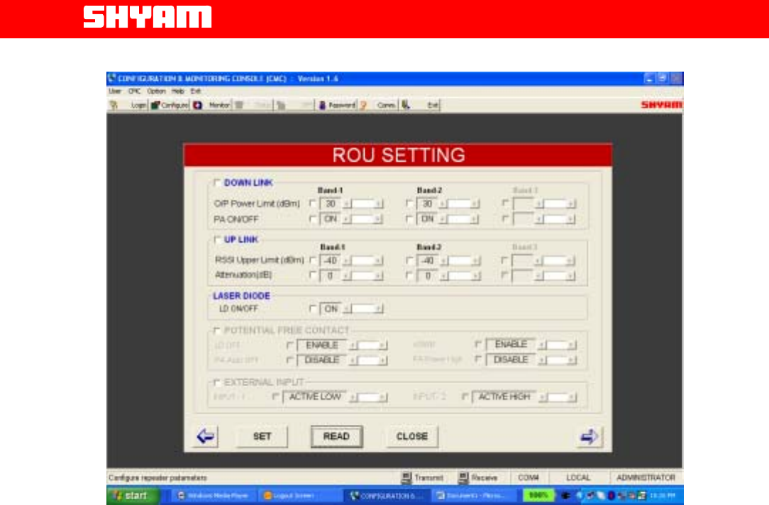
d) Settings ROU
After login, following settings as per Figure 9 are carried out:
• Output power limits in downlink for Band 1 Band 2 are
specified.
• PA ON/OFF as per requirement in Band 1 Band 2. Both the
PAs remain in ON condition under normal circumstances.
• RSSI limits in Band 1 & Band 2 in uplink path are specified.
• Attenuation inserted in Band 1 & Band 2 , values are indicated.
• Laser Diode ON or OFF setting can be made as per
requirement. It will remain in ON condition during normal
working of the system.
All Rights Reserved Shyam Telecom Limited Page
17 / 40
Next Generation
Signal Enhancement
Figure 9: ROU settings
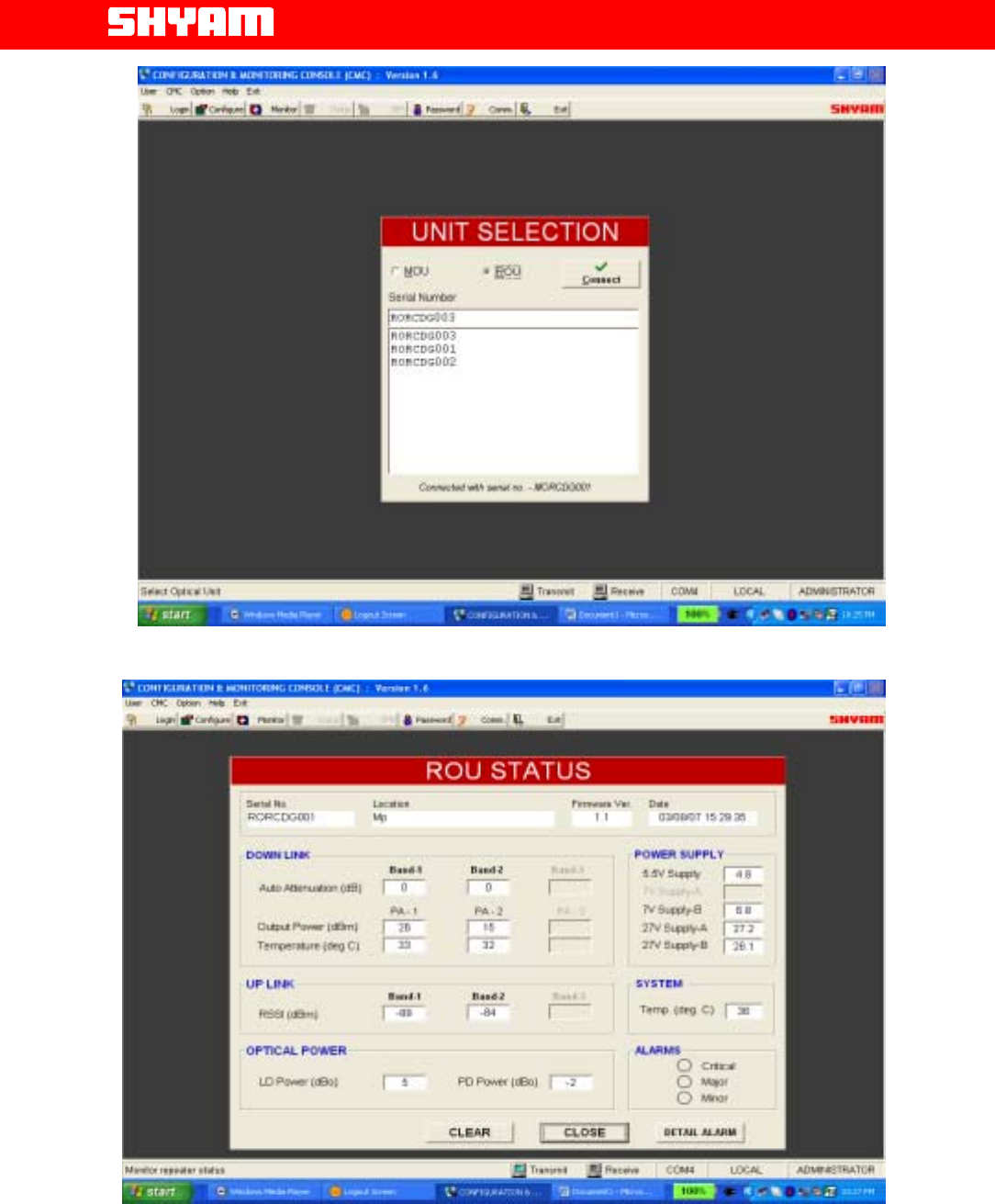
One MOU supports up to 8 DBROUs, unit selection can be made for a
particular DBROU as per Figure 10 for settings etc.
e) DBROU Status (Figure 11)
Parameters as indicated below are monitored:
• Attenuation inserted In Downlink path in Band 1 & Band 2 in auto mode
is indicated.
• Real time Output power in Band 1 Band 2 is indicated.
• Real time value of RSSI in Uplink path in Band 1 & Band 2 is indicated.
• Real time LD optical power is displayed.
• Real time PD optical power is displayed.
• Real time values of power supply voltages 5.5 V, 7 V supply B, 27 V
supply A & 27 V supply B.
• System temperature is indicated.
• Categories of alarms prevailing in the system are displayed.
All Rights Reserved Shyam Telecom Limited Page
18 / 40
Next Generation
Signal Enhancement
Figure 10: Unit Selection
Figure 11: ROU Status Monitoring Window

All Rights Reserved Shyam Telecom Limited Page
19 / 40
Next Generation
Signal Enhancement
Clicking “Detail Alarm” can check alarms on DBROU
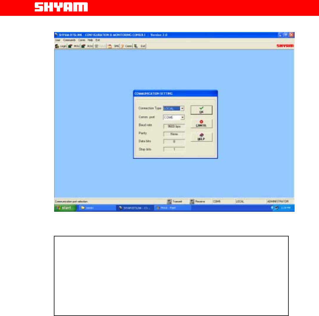
III) Communication Settings (Figure 12)
In COMMUNICATION window, user can select serial communication port
of the computer and type of connection between repeater and computer.
There are two types of connections viz. Local and Remote.
a) Local Connection
In this type of connection user computer COM Port and repeater’s USB
Port are connected directly using cable. Sequence is as under:
• Click the “COMM.” on the command bar to display the
COMMUNICATION window.
• Select the Connection Type as “LOCAL”
• Select the computer’s Comm. Port where the repeater is
connected.
• Click “OK”.
b) Remote Connection
In this type of connection, User communicates remotely with the
system using wireless Modem / Cell phone.
To connect:
• Click the “COMM.” on the command bar to display the
COMMUNICATION window.
• Select the Connection Type as “REMOTE”
• Select the computer’s Comm. Port where the wireless
Modem is connected.
• Click “OK”.
• Now click the “DIALUP” on the command bar to display the
DIALUP window.
• Enter / Select the repeater phone number.
• Click the “DIAL” and wait (maximum 60 seconds) for
connection.
• A message “CONNECTED” will appear on the screen after
the connection is established.
Click “DISCONNECT” to break the connection.
All Rights Reserved Shyam Telecom Limited Page
20 / 40
Next Generation
Signal Enhancement
Figure 12: Communication Settings
IV) Security Settings (Figure 13)
The system has two levels of permitting Log in to the repeater to avoid
unauthorized operation.
The levels are: ADMINISTRATOR & SUPERVISOR.
Each level has a specific password. The password for each level can be
changed at intervals. ADMINISTRATOR has rights to perform all
functions Viz. Configuration, Monitoring etc. Whereas the SUPERVISOR
ha jurisdiction to perform limited functions like monitoring of alarms,
establishing communication etc.
CAUTION
When the communication between repeater & PC/Laptop is in progress
through USB:
• Do not remove cable from the USB port.
• Do not switch off the repeater.
In case the communication is not required any more, click at EXIT before
removing cable from USB port to avoid hanging of the PC/Laptop. In case
the PC/Laptop goes in to hanging mode, it has to be restarted afte
r
closing/switching OFF & ON the repeater.