Silex Technology SXPCEACDB SX-PCEAC-DB User Manual
Silex Technology, Inc. SX-PCEAC-DB
Contents
- 1. User manual
- 2. Users Manual
User manual
(1/18)
CONFIDENTIAL
© silex technology, Inc.
Title:
PCI Express Half mini card WLAN module
SX-PCEAC-DB
Drawing Type : User’s manual
Date : March 18, 2016

Date:March 18, 2016
(2/18)
CONFIDENTIAL
© silex technology, Inc.
Revision History
Rev.
Description Date Prepared Checked Approved
1
The first edition. Mar.18,16
K.Yoshikawa
Y.Shibuya T.Kometani

Date:March 18, 2016
(3/18)
CONFIDENTIAL
© silex technology, Inc.
Table of Contents
1. Introduction ............................................................................. 4
2. Overview ................................................................................. 4
3. Hardware system block diagram ............................................................ 5
4. Board specifications ..................................................................... 6
4.1. General specifications ......................................................... 6
4.2. Environmental specifications ................................................... 6
4.3. Electrical specifications ...................................................... 7
4.4. Wireless LAN general specifications .............................................. 8
5. Connector interface specifications ....................................................... 10
5.1. PCI Express Mini Card edge pin assignments .................................... 10
6. Mechanical Specifications ............................................................... 12
7. System requirements and quick start guide ................................................ 13
8. Notifications ........................................................................... 15

Date:March 18, 2016
(4/18)
CONFIDENTIAL
© silex technology, Inc.
1. Introduction
This document describes about hardware specifications of “SX-PCEAC-DB”.
2. Overview
SX-PCEAC-DB is the radio module which supports Dual Band IEEE802.11ac/a/b/g/n and PCI express
1.1. This module complies with EU RoHS Directive 2011/65/EC(Lead Free). This module is made up
of an Chipset QCA9880-BR4A (Qualcomm Atheros) which contains a MAC/BBP, 2.4GHz RF front end
circuits and a 5GHz RF front end module AWL9581(Anadigics). Also this module supports high speed
3x3 SU-MIMO and 80MHz bandwidth.
Features
❑ IEEE 802.11ac/a/b/g/n conformity (2.4GHz & 5GHz)
❑ Supports the 3 streams 3 x 3 SU-MIMO system and 80MHz band width for 5GHz.
(Throughput up to 1300Mbps)
❑ Data rates of 1 - 54 Mbps for 802.11b/g, 6 - 54 Mbps for 802.11a, MCS0-7 for 802.11n and
MCS0-9 for 802.11ac.
❑ Supports IEEE802.11e, IEEE 802.11h and IEEE 802.11i.
❑ Supports PCI express 1.1 as the host IF of wireless LAN
* Not supported MU-MIMO and 160MHz bandwidth.
Date:March 18, 2016
(5/18)
CONFIDENTIAL
© silex technology, Inc.
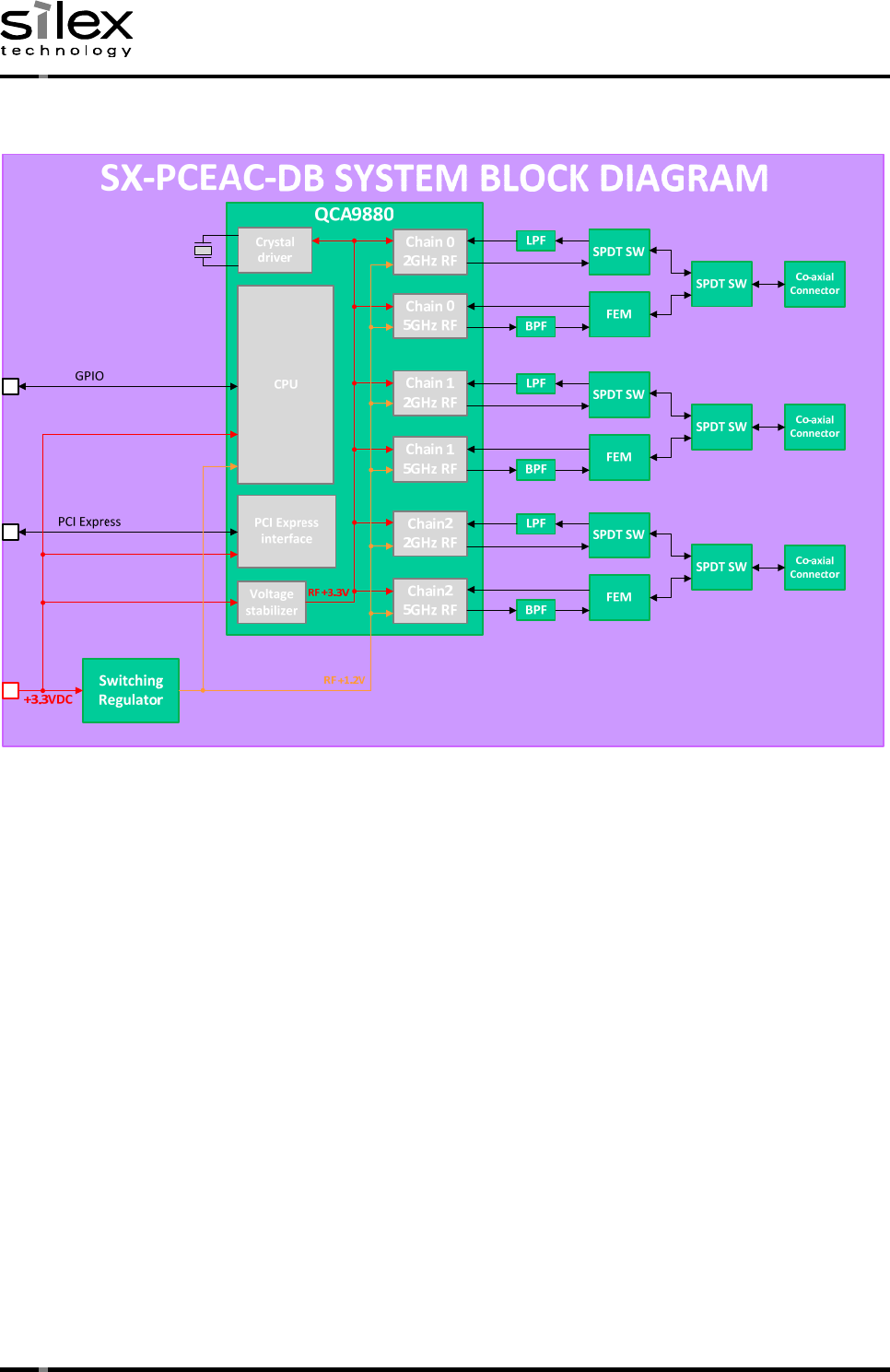
3. Hardware system block diagram
① QCA9880 Wireless Lan base band IC. Generates base band signal.
② Low pass filter Cuts off signal above 2.5GHz.
③ Band pass filter Cuts off signal under 5GHz and above 6GHz.
④ Single pole double throw switch
Switches Tx and Rx of 2.4GHz.
⑤ Fron end module Integrates a 5GHz power amplifier, a 5GHz low noise and
Tx/Rx select swtich.
⑥ Single pole double throw switch
Switches 2.4GHz and 5GHz.
⑦ Co-axial connector
NOTE1
Antenna port. MHF4 type.
⑧ Crystal driver Generates 40MHz system clock.
⑨ Voltage stabilizer
NOTE2
Stabilize +3.3VDC for RF.
⑩ Switching regulator
NOTE2
Coverts +3.3VDC to +1.2VDC.
NOTE1
Any signals of 1 stream data, 2 stream data and 3 stream data is output from three antennas.
NOTE2
Any voltage source for RF parts are generated/stabilized on the module.(RF +3.3V, RF +1.2V)
RF performance shown in the product spec is not affected by any behaviors of external +3.3V supply.
Date:March 18, 2016
(6/18)
CONFIDENTIAL
© silex technology, Inc.
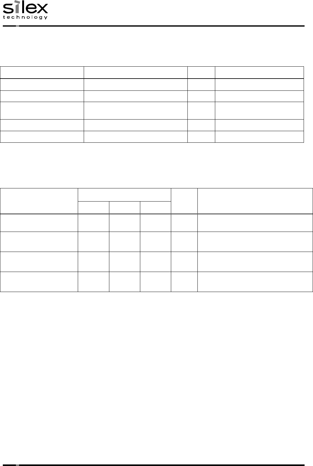
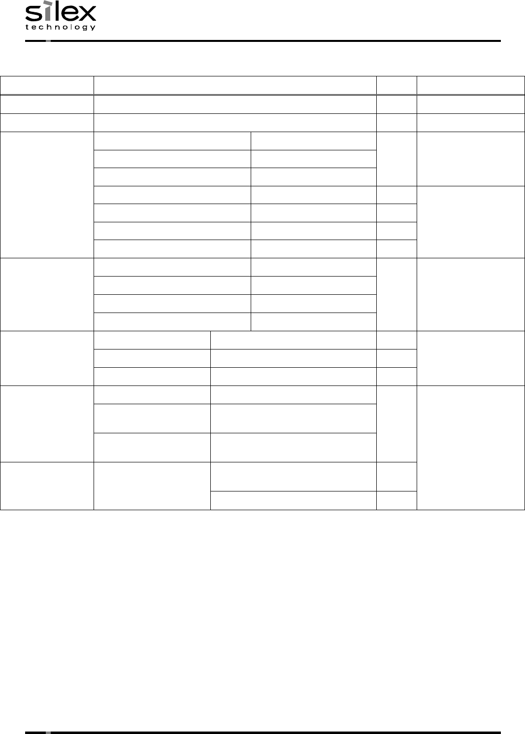
4. Board specifications
4.1. General specifications
Items Specifications Units
Remarks
Connector Type PCI express mini card edge -
Antenna connectors MHF4 Alternative connector x 3
pcs
Device Interfaces PCI Express Mini Card v1.2 - Signal definitions : PCI
Express v1.1
RF Interface IEEE802.11ac/a/b/g/n -
MTBF 90,000 h Min.
4.2. Environmental specifications
Items Specifications Units
Remarks
Min. Typ. Max.
Operating Temperature
-20 - +60 ℃ Case temperature
After assembled with powered
Operating humidity 20 - 80 %RH Non condensing
After assembled with powered
Assembled storage
temperature -20 - +85 ℃ After assembled with no-powered
Storage humidity 20 - 85 %RH Non condensing
After assembled with no-powered
Date:March 18, 2016
(7/18)
CONFIDENTIAL
© silex technology, Inc.
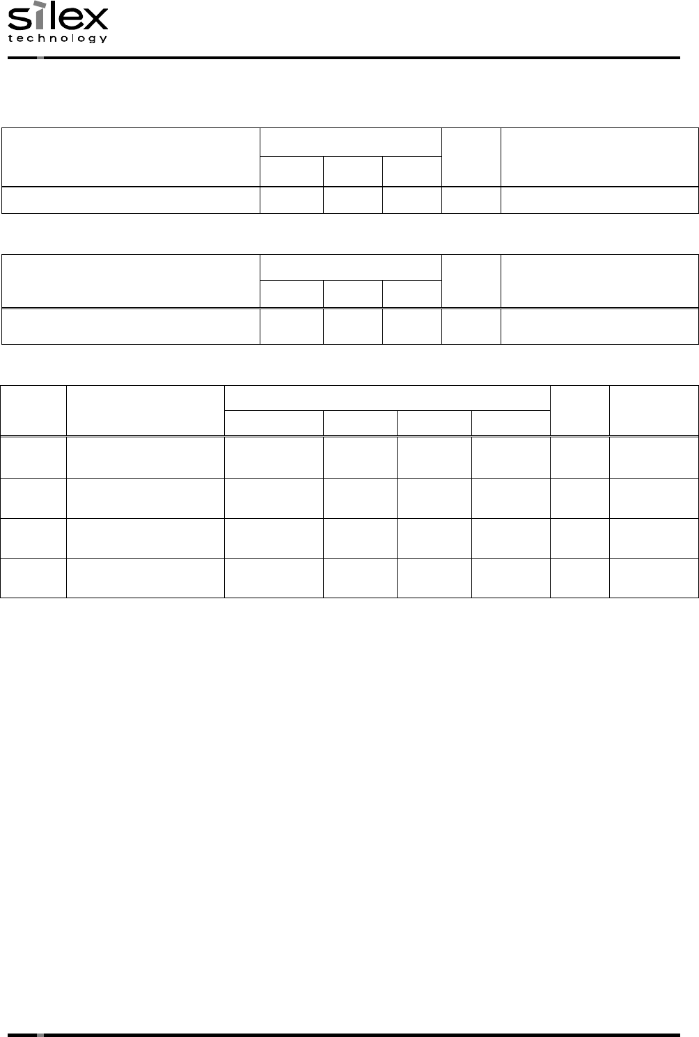
4.3. Electrical specifications
Absolute Maximum Ratings (Ta=+25℃)
Items
Specifications
Units
Remarks
Min. Typ. Max.
Main Power supply voltage (VDD) -0.3 - +3.6 V
Recommended Operating Conditions (Ta=+25℃)
Items Specifications Units
Remarks
Min. Typ. Max.
Main Power supply voltage (VDD) +3.135
+3.3 +3.465
V
Digital logic signal level (Ta=+25℃)
Items Parameters Specifications Units
Remarks
Sink current
Min. Typ. Max.
VIH Input High Voltage 0.7 x VDD
- - V
VIL Input Low Voltage - - 0.3 x VDD
V
VOH Output High Voltage
0.9 x VDD
- - V
VOL Output Low Voltage - - 0.1 x VDD
V
※All voltage source for the analog RF power supply is internally regulated in the module, and RF
performance described in this document is not affected by any variation for external power source.
Date:March 18, 2016
(8/18)
CONFIDENTIAL
© silex technology, Inc.
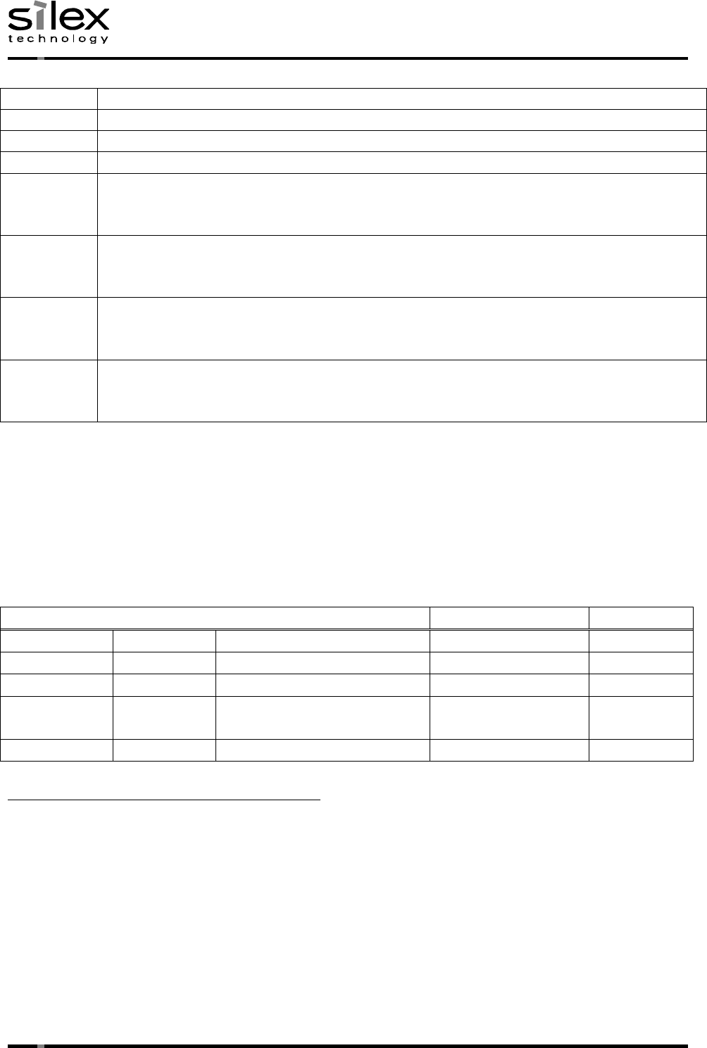
4.4. Wireless LAN general specifications
Items Specifications Units
Remarks
Chipset QCA9880-BR4A (Qualcomm Atheros) -
Country code US -
Center frequency
11a/11nHT20/11acVHT20 5180 - 5825
MHz US:W52/W53/W56/W58
11n HT40/11ac VHT40 5190 - 5795
11ac VHT80 5210 - 5775
11b 2412 - 2462 MHz
US:2412–2462MHz
11g 2412 - 2462 MHz
11ng HT20 2412 - 2462 MHz
11ng HT40 2422 - 2452 MHz
Channel spacing 11a/11nHT20/11acVHT20 20
MHz
11nHT40/11acVHT40 40
11acVHT80 80
11b/11g/11ngHT20/11ngHT40 5
Link rate 11b 1,2,5.5L,5.5S,11L,11S Mbps
11a/g 6,9,12,18,24,36,48,54 Mbps
11ng/na/ac 1-3 Stream
MCS0,1,2,3,4,5,6,7,8,9 -
Modulation type 11b DSSS(CCK,DQPSK,DBPSK)
-
11a/11g OFDM
(64QAM,16QAM,QPSK,BPSK)
11na/11ng/11ac OFDM
(256QAM,64QAM,16QAM,QPSK,BPSK)
Hardware encryption
engine
WiFi RC4(64-128bit) -
AES(128-256bit) -
Date:March 18, 2016
(9/18)
CONFIDENTIAL
© silex technology, Inc.
Usable channel list
11b Ch.1, Ch.2, Ch.3, Ch.4, Ch.5, Ch.6, Ch.7, Ch.8, Ch.9, Ch.10, Ch.11
11g Ch.1, Ch.2, Ch.3, Ch.4, Ch.5, Ch.6, Ch.7, Ch.8, Ch.9, Ch.10, Ch.11
11ng HT20 Ch.1, Ch.2, Ch.3, Ch.4, Ch.5, Ch.6, Ch.7, Ch.8, Ch.9, Ch.10, Ch.11
11ng HT40 Ch.3, Ch.4, Ch.5, Ch.6, Ch.7, Ch.8, Ch.9
11a Ch.36, Ch.40, Ch.44, Ch.48, Ch.52, Ch.56, Ch.60, Ch.64
Ch.100, Ch.104, Ch.108, Ch.112, Ch.116, Ch.120, Ch.124, Ch.128, Ch.132, Ch.136, Ch140
Ch.145, Ch.149, Ch.153, Ch.157, Ch.161, Ch.165
11n HT20
11ac VHT20
Ch.36, Ch.40, Ch.44, Ch.48, Ch.52, Ch.56, Ch.60, Ch.64
Ch.100, Ch.104, Ch.108, Ch.112, Ch.116, Ch.120, Ch.124, Ch.128, Ch.132, Ch.136, Ch140
Ch.145, Ch.149, Ch.153, Ch.157, Ch.161, Ch.165
11n HT40
11ac VHT40
Ch.38, Ch.46, Ch.54, Ch.62
Ch.102, Ch.110, Ch.118, Ch.126, Ch.134
Ch.151, Ch.159
11ac VHT80 Ch.42, Ch.58
Ch.106, Ch.122
Ch.155
・Above region code relating channel list is programmed in the module by module manufacturer
(Silex).
・Since programmed region code and channel list is binary data and user cannot know the structure
of program, any customers cannot change usable channels.
Operation theory
Client mode (Station)
Operation frequencies Active/Passive ad-hoc mode
2.4GHz band 11b/g/n 2412-2462MHz Active scan No
W52 11a/an/ac 5180-5240MHz Active scan No
W53 11a/an/ac 5260-5320MHz Passive scan No
W56 11a/an/ac 5500-5700MHz
※IC:5600-5650MHz disable Passive scan No
W58 11a/an/ac 5745-5825MHz Active scan No
Compliance with FCC requirement 15.407(c)
Data transmission is always initiated by software, which is the passed down through the MAC,
through the digital and analog baseband, and finally to the RF chip. Several special packets
are initiated by the MAC. These are the only ways the digital baseband portion will turn on the
RF transmitter, which it then turns off at the end of the packet. Therefore, the transmitter
will be on only while one of the aforementioned packets is being transmitted. In other words,
this device automatically discontinue transmission in case of either absence of information to
transmit or operational failure.
Date:March 18, 2016
(10/18)
CONFIDENTIAL
© silex technology, Inc.
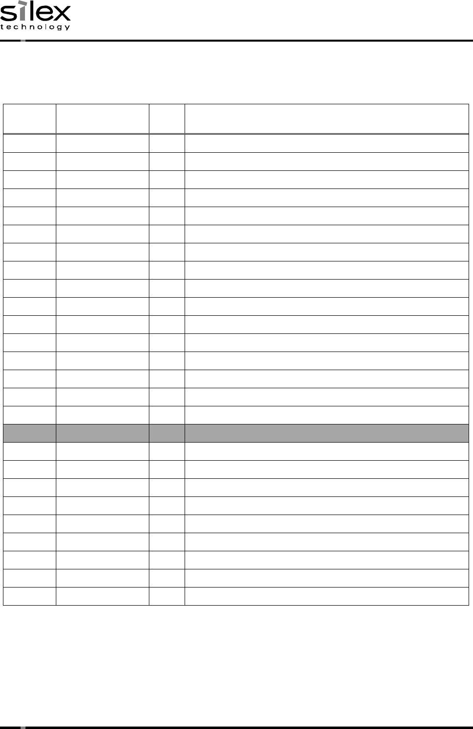
5. Connector interface specifications
5.1. PCI Express Mini Card edge pin assignments
Pin
Numbers
Pin Names Types
Descriptions
1 RESERVED OD WAKE_L
2 +3.3Vaux PWR
3 RESERVED IO Connected to GPIO.
4 GND GND
5 RESERVED IO Connected to GPIO.
6 RESERVED NC
7 RESERVED OD CLKREQ_L
8 RESERVED NC
9 GND GND
10 RESERVED NC
11 REFCLK- IA PCI Express differential reference clock (100MHz)
12 RESERVED NC
13 REFCLK+ IA PCI Express differential reference clock (100MHz)
14 RESERVED NC
15 GND GND
16 RESERVED NC
Mechanical key
17 RESERVED NC
18 GND GND
19 RESERVED NC
20 RESERVED IO Disable wireless module. On board Pull-up(10kohm)
21 GND GND
22 PERST_L IL Express reset. Internal weak pull-down
23 PERn0 OA Module : Differential data transmit
24 +3.3Vaux PWR
25 PERp0 OA Module : Differential data transmit
Date:March 18, 2016
(11/18)
CONFIDENTIAL
© silex technology, Inc.
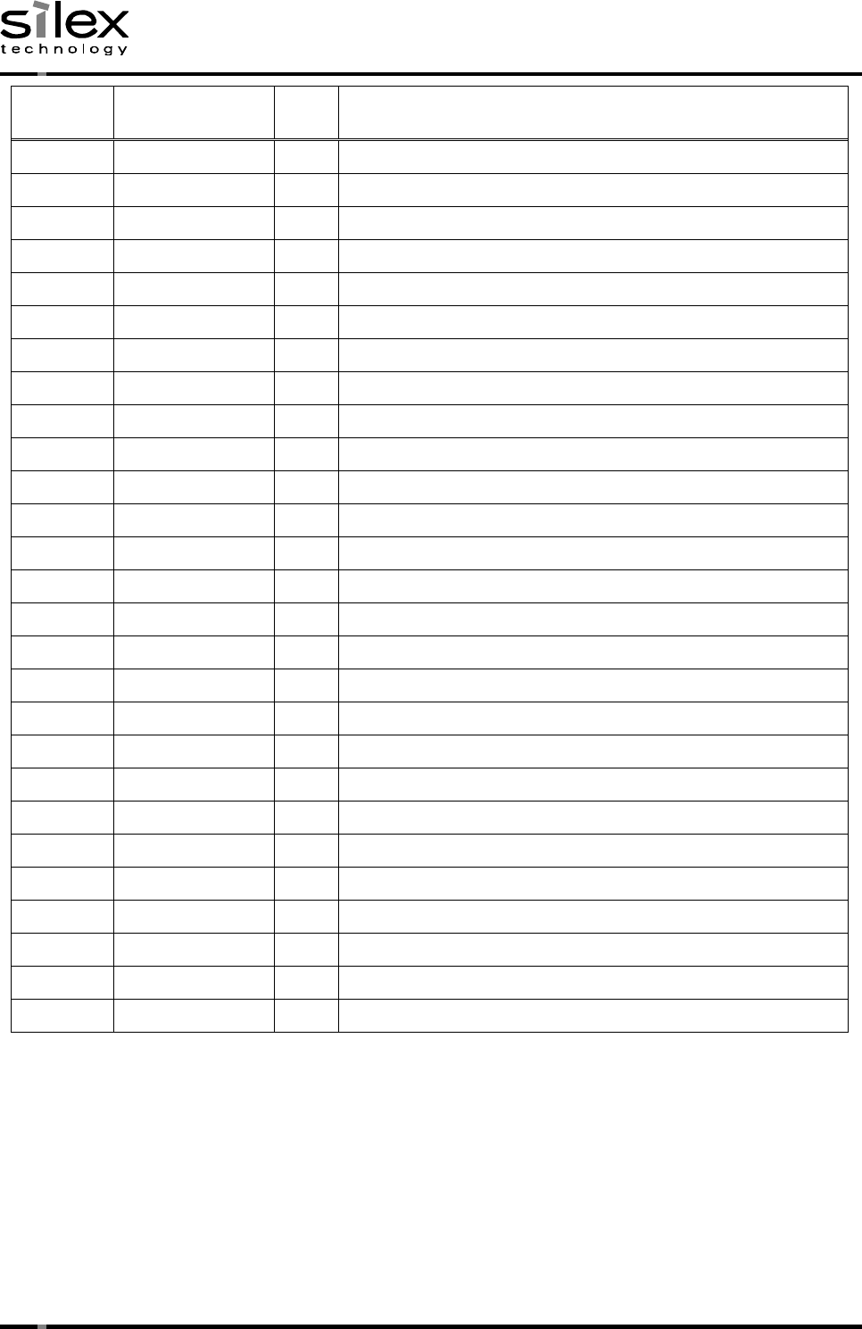
Pin
Numbers Pin Names Types
Descriptions
26 GND GND
27 GND GND
28 RESERVED NC
29 GND GND
30 RESERVED NC
31 PETn0 IA Module : Differential data receive
32 RESERVED NC
33 PETp0 IA Module : Differential data receive
34 GND GND
35 GND GND
36 RESERVED NC
37 RESERVED NC
38 RESERVED NC
39 RESERVED NC Connected to pin 41 internally
40 GND GND
41 RESERVED NC Connected to pin 39 internally
42 RESERVED NC
43 RESERVED GND Connected to GND
44 RESERVED IO Connected to GPIO.
45 RESERVED IO Connected to GPIO
46 RESERVED NC
47 RESERVED IO Connected to GPIO.
48 RESERVED NC
49 RESERVED NC
50 GND GND
51 RESERVED NC
52 +3.3V PWR
NC : No Connection.
IO : Digital bidirectional pin.
IA : Analog input signal.
OA : Analog output signal.
OD : Digital output signal with open drain.
IL : Input signal with weak internal pull-down.
PWR : Power signal.
GND : Ground signal.
©
silex technology, Inc.
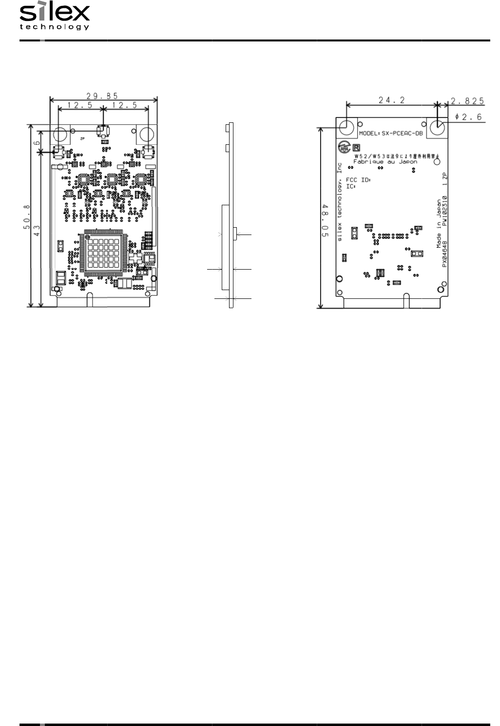
6.
Mechanical Specifications
*Solder thickness=0.1mm
All
dimension tolerances are +/
silex technology, Inc.
Mechanical Specifications
*Solder thickness=0.1mm
dimension tolerances are +/
TOP View
silex technology, Inc.
Mechanical Specifications
*Solder thickness=0.1mm
dimension tolerances are +/
TOP View
Mechanical Specifications
dimension tolerances are +/
-
0.15 mm, unless otherwise specified.
(12/
18
0.15 mm, unless otherwise specified.
4.00
2.10
1.00
SIDE View
18
)
0.15 mm, unless otherwise specified.
4.00
2.10
1.00
0.15 mm, unless otherwise specified.
BOTTOM View
Date
:
CONFIDENTIAL
Thickness +/
BOTTOM View
:
March 18, 2016
CONFIDENTIAL
+/-
0.15mm
Thickness +/
-
0.25mm
March 18, 2016
CONFIDENTIAL
0.15mm
0.25mm
Date:March 18, 2016
(13/18)
CONFIDENTIAL
© silex technology, Inc.
7. System requirements and quick start guide
1) System requirements
Prepare the host CPU board whose spec requirements are shown below.
System pecifications
Items Descriptions
MCU (CPU) ARM based 1.0GHz or greater SoC from any companies.
Eg. Freescale i.MX6SX – 1200MHz
Memory size ROM : 512MB, RAM : 1GB or greater
OS Linux any kernel distribution
Host interface PCI Express 1.1
2) Install the driver which is provided by Silex to the CPU board.
Any other 3rd party’s software shall be rejected due to Subsystem ID mismatch.
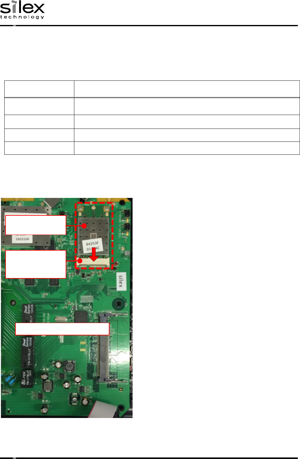
3) Install the SX-PCEAC-DB board to the CPU board.
CPU board
SX-PCEAC-DB
Board
PCI Express
mini Card
connector
Date:March 18, 2016
(14/18)
CONFIDENTIAL
© silex technology, Inc.
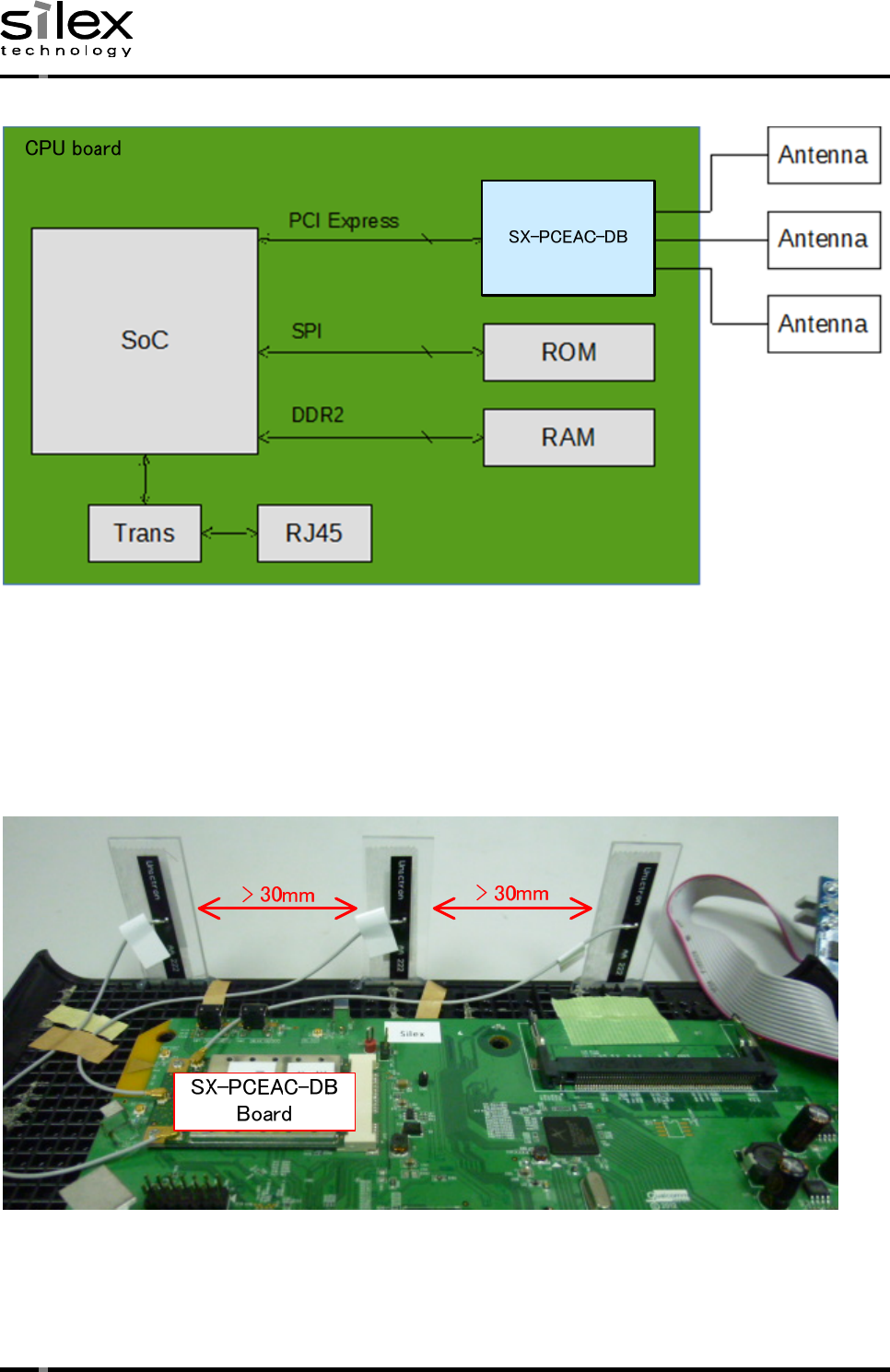
System block diagram
4) Antenna location
Attach the antenas to the co-axial connectors on the SX-PCEAC-DB board. This product doesn’
t include the CPU board and the plastic case. The figure below is an assumed example of embedded
system. Both the baseboard and the case does not affect to RF performance including Antenna
performance as long as distance between each antenna is farther than 30mm. Installater must keep
this distance when installing this module.

Date:March 18, 2016
(15/18)
CONFIDENTIAL
© silex technology, Inc.
8. Notifications
FCCID :N6C-SXPCEACDB
IC :4908A-SXPCEACDB
Regulatory notice
Channel Selection
For product available in the USA/Canada market, only channel 1~11 can be operated. Selection
of other channels is not possible.
Fcc Rules Part 15
FCC CAUTION
Changes or modifications not expressly approved by the party responsible for compliance could
void the user’s
authority to operate the equipment.
FCC Rules, Part 15 §15.19(a)(3) / IC RSS Gen §8.4
Below sentences must be indicated on the final product which contains this module inside.
This device complies with part 15 of FCC Rules and Industry Canada’s licence-exempt RSSs.
Operation is subject
to the following two conditions: (1) this device may not cause harmful interference, and (2)
this device must accept any interference received, including interference that may cause
undesired operation.
Le présent appareil est conforme aux CNR d’Industrie Canada applicables aux appareils radio
exempts de licence. L’exploitation est autorisée aux deux conditions suivantes : 1) l’appareil
ne doit pas produire de brouillage; 2) l’utilisateur de l’appareil doit accepter tout brouillage
radioélectrique subi, même si le brouillage est susceptible d’en compromettre le fonctionnement.
FCC Rules Part 15 Subpart C §15.247 and Subpart E / IC RSS-102 §2.6
This equipment complies with FCC/IC radiation exposure limits set forth for an uncontrolled
environment and meets the FCC radio frequency (RF) Exposure Guidelines and RSS-102 of the IC
radio frequency (RF) Exposure rules. This equipment should be installed and operated keeping
the radiator at least 20cm or more away from person’s body.
Cet équipement est conforme aux limites d ’ exposition aux rayonnements énoncées pour un
environnement non contrôlé et respecte les règles les radioélectriques (RF) de la FCC lignes
directrices d'exposition et d’exposition aux fréquences radioélectriques (RF) CNR-102 de l’
IC. Cet équipement doit être installé et utilisé en gardant une distance de 20 cm ou plus entre
le radiateur et le corps humain.
Date:March 18, 2016
(16/18)
CONFIDENTIAL
© silex technology, Inc.
FCC Rules Part 15 Subpart E §15.407(c)
Compliance with FCC requirement 15.407(c)
Data transmission is always initiated by software, which is the passed down through the MAC,
through the digital and analog baseband, and finally to the RF chip. Several special packets
are initiated by the MAC. These are the only ways the digital baseband portion will turn on the
RF transmitter, which it then turns off at the end of the packet. Therefore, the transmitter
will be on only while one of the aforementioned packets is being transmitted. In other words,
this device automatically discontinue transmission in case of either absence of information to
transmit or operational failure.
FCC Rules Part 15 Subpart E §15.407(g)
Frequency Tolerance: +/-20 ppm
FCC Rules Part 15 Subpart C §15.247(g) / Subpart E
This device and its antenna(s) must not be co-located or operation in conjunction with any other
antenna or transmitter.
RSS-Gen §8.3
This radio transmitter 4908A-SXPCEACDB has been approved by Industry Canada to operate with
the antenna types listed below with the maximum permissible gain and required antenna impedance
for each antenna type indicated. Antenna types not included in this list, having a gain greater
than the maximum gain indicated for that type, are strictly prohibited for use with this device.
Le numéro IC du présent émetteur radio 4908A-SXPCEACDB a été approuvé par Industrie Canada pour
fonctionner avec les types d'antenne énumérés ci-dessous et ayant un gain admissible maximal
et l'impédance requise pour chaque type d'antenne. Les types d'antenne non inclus dans cette
liste, ou dont le gain est supérieur au gain maximal indiqué pour ce type, sont strictement
interdits pour l'exploitation avec cet appareil.
Certified antenna list
Part number Vendor Antenna Gain
2.4GHz
W52 W53 W56 W58 Units
146153 Molex +3.25 +5.00 +5.00 +5.00 +5.00 dBi
H2B1PC1A1C (AA258) Unictron +2.90 +4.40 +4.40 +4.40 +4.40 dBi
H2B1PD1A1C (AA222) Unictron +2.80 +4.20 +4.20 +4.20 +4.20 dBi

Date:March 18, 2016
(17/18)
CONFIDENTIAL
© silex technology, Inc.
RSS-247 Issue 1 May 2015
Radio Standards Specification RSS-247, Issue 1, Digital Transmission Systems (DTSs), Frequency
Hopping Systems (FHSs) and Licence-Exempt Local Area Network (LE-LAN) Devices, is a new standard
to replace annexes 8 and 9 of RSS-210, Issue 8, Licence-exempt Radio Apparatus (All Frequency
Bands): Category I Equipment.
At the date of publication of this standard, devices covered under the scope of this document
will no longer be certified under RSS-210, Issue 8.
Le Cahier des normes radioélectriques 247, 1re édition, Les systèmes de transmission numérique
(STN), les systèmes à sauts de fréquence (SSF) et les dispositifs de réseaux locaux exempts de
licence (RL-EL), remplace les annexes 8 et 9 du CNR-210, 8e édition, Appareils radio exempts
de licence (pour toutes les bandes de fréquences) : matériel de catégorie I.
À la date de publication de la présente norme, les dispositifs visés par ce document ne seront
plus certifiés conformément au CNR-210, 8e édition.
Frequency Band 5150 – 5250 MHz
LE-LAN devices are restricted to indoor operation only in the band 5150-5250 MHz.
Les dispositifs LAN-EL sont restreints à une utilisation à l'intérieur, dans la bande
5150-5250MHz.
High-power radars are allocated as primary users (i.e. priority users) of the bands 5250-5350
MHz and 5650-5850 MHz and that these radars could cause interference and/or damage to LE-LAN
devices.
Les radars de haute puissance sont désignés comme utilisateurs principaux (c’ est-à dire
utilisateurs prioritaires) pour les bandes 5250-5350 MHz et 5650-5850 MHz, et que ces radars
peuvent provoquer du brouillage et/ou des dommages aux dispositifs LAN-EL.

Date:March 18, 2016
(18/18)
CONFIDENTIAL
© silex technology, Inc.
WARNING:
The FCC / The Industry Canadaregulations provide that changes or modifications not expressly
approved by the party responsible for compliance could void the user’sauthority to operate the
equipment.
Manual and Product Labeling information To The End User
The end user manual shall include all required regulatory information/warning as show in this
manual.And when this module is installed in the host product, you must include a “Contain FCC
ID : N6C-SXPCEACDB”and a “Contain IC: 4908A- SXPCEACDB” in the label of the host product.
This module is designed for embedded purpose into the general electric devices, and is not
designed for high reliability demands like aircraft instruments, nuclear control instruments,
high reliability medical instruments, high reliability security instruments or any other devices
required extremely high reliability and quality.
• As this module communicates by radio wave, it is strongly recommended to use some security
system to prevent unexpected information leakage to others.
• This module is a radio module for embedded purpose. Please understand functions and features
of this module, and evaluate as the final product which has this module embedded. Also, as
evaluation of EMC conformity of this module has not been performed, EMC conformity evaluation
and application must be performed with the final product which this module is embedded.
• This module will effect to some other device or be affected by the some other device using
the same frequency band.Please investigate the environment to use this module beforehand.
• Disassembling or modifying the radio module leads to punishment based on radio law.
• This module is the embedded module that has the exposed connectors or some devices.Please be
careful for electro static, condensing, and other dusts.
• “The OEM integrator has to be aware not to provide information to the end user regarding how
to install or remove this RF module in the user’s manual of the end product which integrates
this module.”
IMPORTANT NOTE: In the event that these conditions cannot be met (for example co-location with
another transmitter), then the FCC / IC authorization is no longer considered valid and the
FCC / IC ID cannot be used on the final product. In these circumstances, the OEM integrator
will be responsible for reevaluating the end product (including the transmitter) and obtaining
a separate FCC / IC authorization. As long as a condition above is met, further transmitter
test will not be required. However, the OEM integrator is still responsible for testing their
end product for any additional compliance requirements required with this module installed (for
example, digital device emissions, PC peripheral requirements, etc.