Sleep Number 3000H Part 15 Low Power Communication Device Transmitter User Manual 59975Cov JR indd
Select Comfort Corp Part 15 Low Power Communication Device Transmitter 59975Cov JR indd
Contents
- 1. User Manual 1
- 2. User Manual 2
User Manual 1

Welcome to your
Sleep Number® Bed
X 4000 and 5000 model
assembly instructions inside
45
80

35
70

Welcome and
Congratulations
55
Welcome and Congratulations,
Congratulations on your purchase of The Sleep Number Bed by Select Comfort™! You’re
about to join more than 5 million people who’ve traded their innerspring mattresses for
the most innovative sleep surface ever. The technology behind the SLEEP NUMBER® bed
is one that recognizes the unique sleeping needs of every individual, which vary according
to comfort preference, body type, height, weight, sleeping position, and other health and
lifestyle factors. By creating a fully personalized sleep surface, your new Sleep Number® bed
offers you customized comfort that can signifi cantly improve your sleep quality.
You’ll enjoy years of the latest generation of sleep comfort and technology in your
Sleep Number® bed. Our commitment to constant innovation, value and customer satisfaction
has repeatedly earned us the Consumers Digest Best Buy award. Sleep Number® bed owners
like you have made us the No. 1 bedding retailer year after year, as ranked by Furniture/Today.
We invite you to tell your friends and neighbors about this revolutionary product that can
help them attain the most comfortable sleep possible. When your referral results in a purchase,
you’ll earn valuable rewards* that will make it easier for you to add another Sleep Number®
bed to your home and ensure improved sleep for your children or your guests.
We thank you for your purchase and wish you years of personal comfort and restful sleep.
William R. McLaughlin
President & CEO
My Sleep Number® is 55
1
* See Owners’ COMFORT CLUB® Rewards on page 38.

Foundation
Assembly
WHAT’S INSIDE
S
ettin
g
up
y
our new
S
L
EE
P
N
UMB
E
R
®
bed onl
y
takes about an hour, but
y
ou’ll en
j
o
y
the benefits of better
sleep for
y
ears to come. You won’t need an
y
tools and, althou
g
h it’s nice to have a helper,
y
ou can do it b
y
yoursel
f
. First, you’ll need to remove your old bed.
N
e
xt, we’
ll
gui
d
e you step-
b
y-step t
h
roug
h
assem
bl
ing t
h
e
foundation, positionin
g
the mattress and attachin
g
the Firmness Control
™
S
y
s
t
em.
T
hen,
y
ou’ll learn how to find
yo
u
r
S
l
eep
N
umber® sett
i
ng.
A
nd,
fi
nally, the best part—you can luxuriate in the personalized com
f
ort o
f
your
S
l
ee
p
N
u
m
be
r
®
bed.
u
Foundation Assembl
y
....................................
p
g 3
u
M
attress Assem
bly
.........................................
pg
11
u
Firmness Contro
l
™
S
ystem
.............................
pg
23
u
FCC Users In
f
ormation
..................................
pg
2
6
u
M
attress
C
are
.................................................
pg
3
1
u
A
ccesso
ri
es
.....................................................
p
g 33
u
Warrant
y
and Comfort Club
®
.........................
p
g 3
5
2 3
Note: Texture and surface appearance may vary
.

Foundation
Assembly
4
BEFORE YOU BEGIN
X Carefully check the contents of your foundation boxes
X Decide where to put your new bed
X Make sure there’s an electric power source nearby
for use with your Firmness Control™ System
X Assemble your bed frame if you have one
Your foundation should be assembled directly onto your bed frame
or on the fl oor. Some bed frames have slats that run from one side
of the bed to the other. If your bed frame has slats, position the slats
evenly to support the foundation. If your bed frame has fewer than
three slats, we recommend adding additional slats to ensure
adequate support for your foundation.
Caution: With some styles of bed frames, the foundation length
may extend beyond the frame’s support legs. This situation makes it
possible for the frame to tip when signifi cant weight is placed at the
foot of the bed. Please use caution when sitting or placing weight
on the foot of the bed when using these types of frames.
X King foundation
The King foundation consists of two Twins side by side. Complete
the assembly of one unit, assemble the second, then place side by
side on the bed frame.
If you are missing any items
listed on the following page,
please e-mail Customer
Service at customerservice@
selectcomfort.com or call
1.800.472.7185
TROUBLESHOOTING
For answers to some common
questions regarding your
foundation, see the Frequently
Asked Questions at the end
of this section.
“ I assembled the Sleep Number
bed by myself. My wife was in
doubt at fi rst, but, after sleeping
one night, she said, it was magic
how well she slept without back
pain. Now we sleep longer and
more comfortably than any
previous mattress we’ve owned.”
- C. Clark Shedd, Tucson, AZ
2 each 2 each 2 each 4 each
6 6 6 12
2 4 4 4
2 2 2 4
1 1 1 1
0 0 4 0
Twin Full Queen King
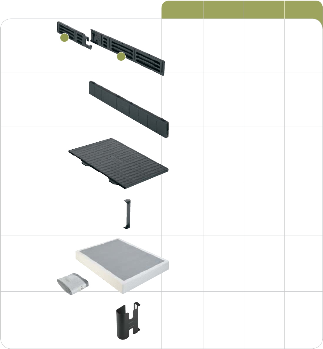
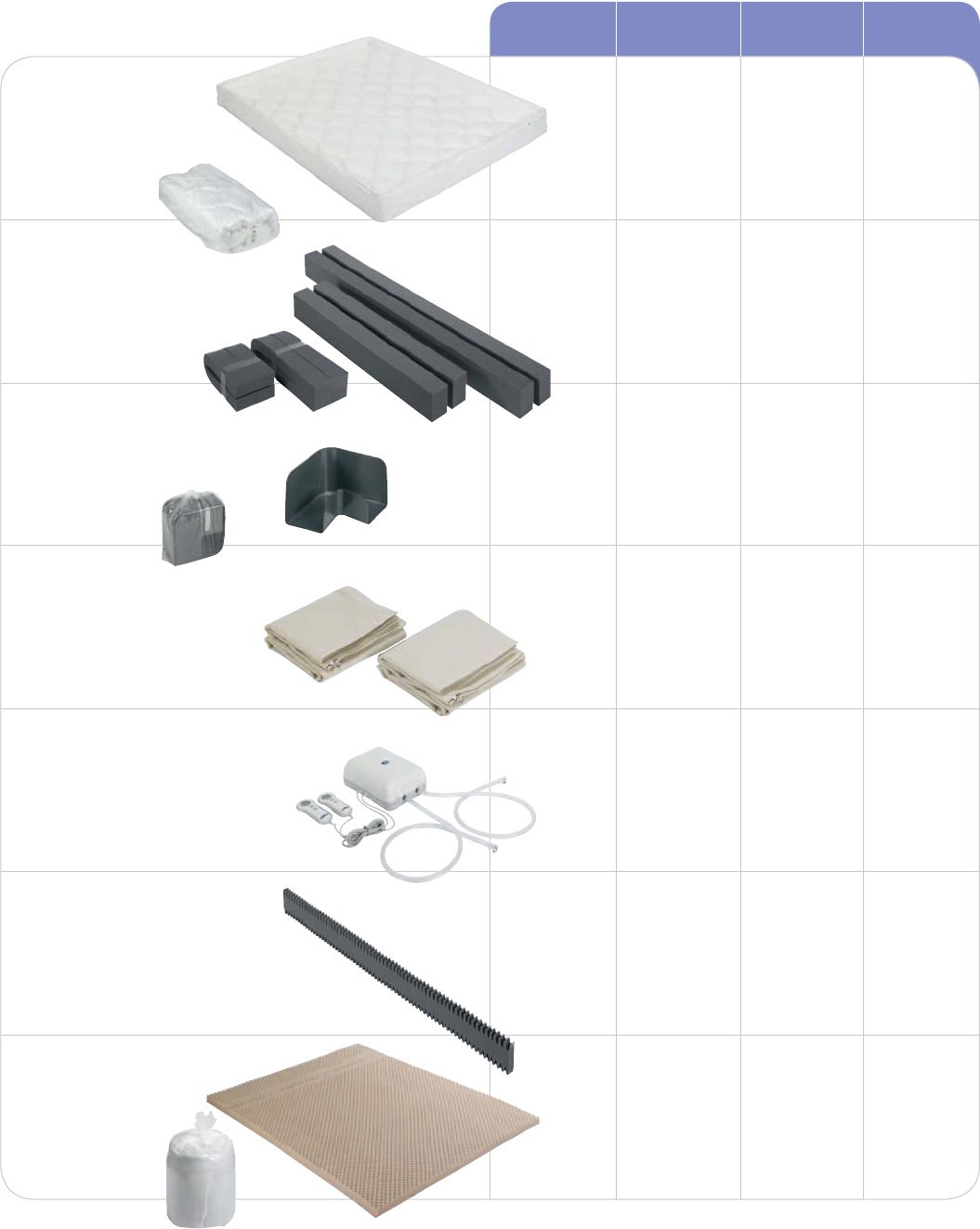
CONTENTS
Carefully check the contents of your foundation boxes
and compare with the list below. Each component is
clearly labeled with the part name and part number.
Side Rails
Support /End Beams
Texture and surface appearance may vary
Pin Components
QUANTITY
5
Expanded Queen only
Corner Brackets
Packaged in the mattress box
Deck Panels
Texture and surface appearance may vary
Fabric Coverlet
Packaged in the
mattress box
Shown as packaged
B
A
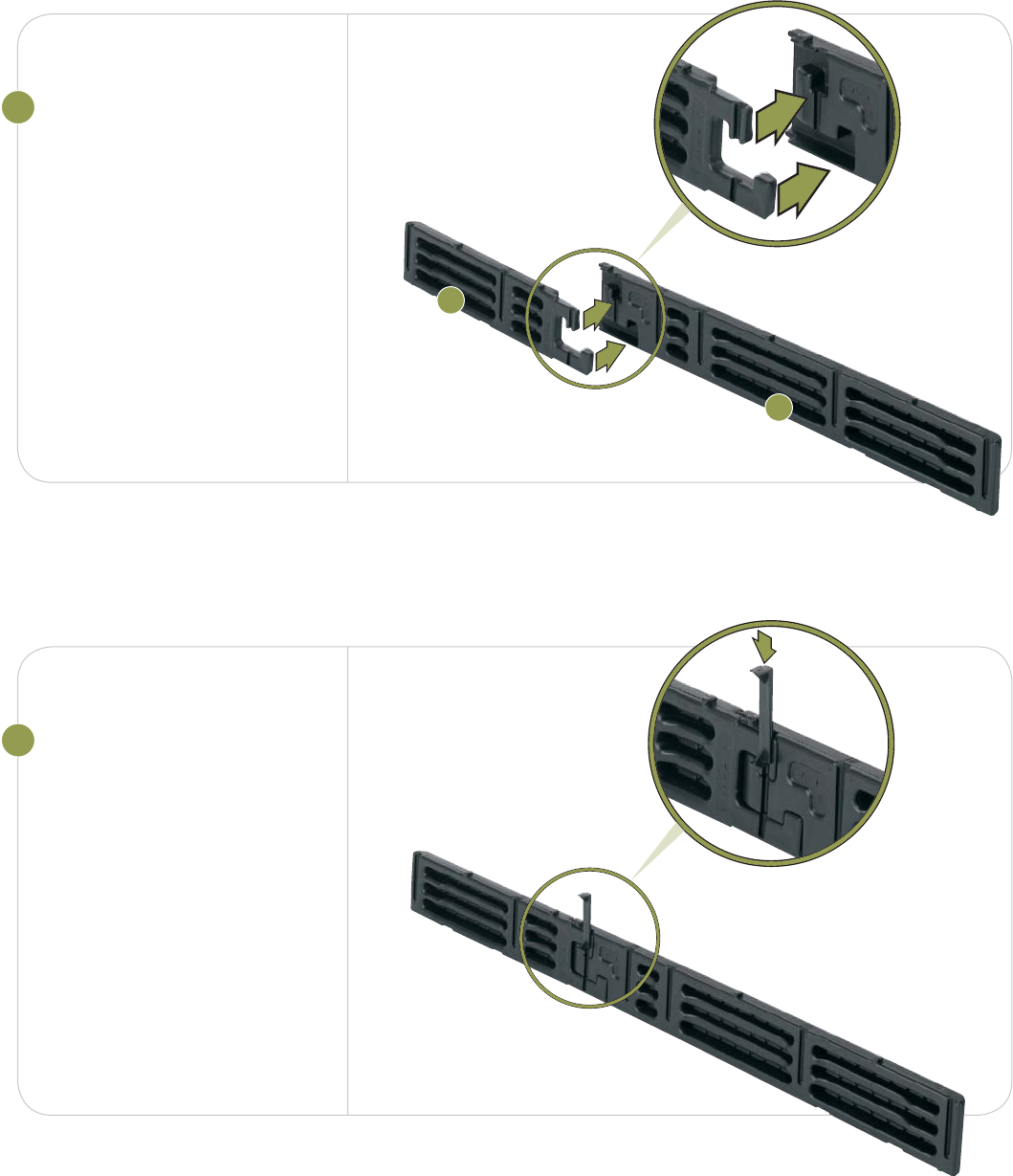
1CONNECT SIDE RAILS
Push the components labeled
A side rail and B side rail
together.
Joints fi t tightly. Push fi rmly.
2INSERT PIN
Slide pins in, “T” end up.
Push fi rmly.
6
B
A
7
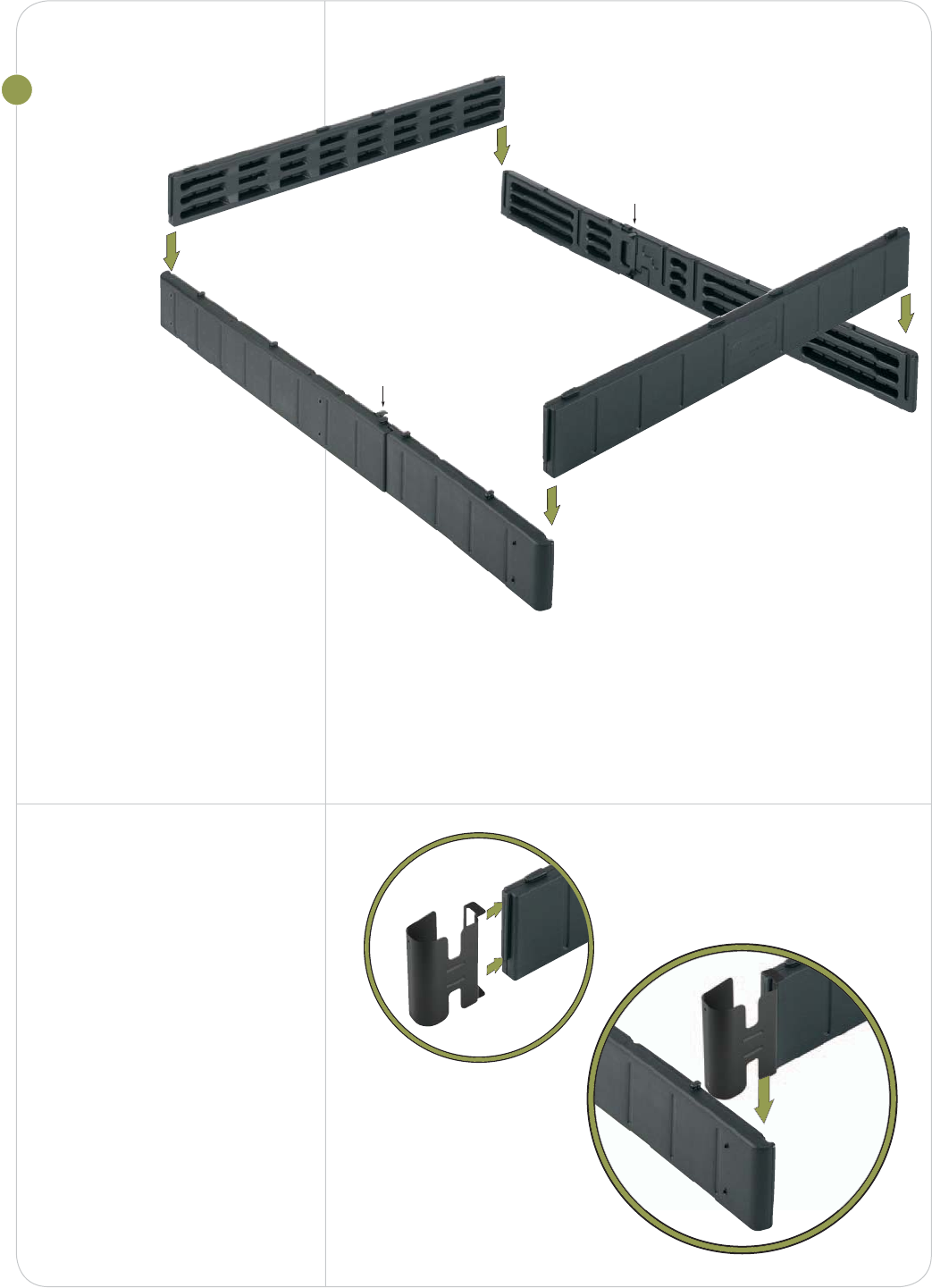
3INSERT SUPPORT/
END BEAMS
For Twin, Queen and
Eastern King models:
– insert support beams
with tabs up and textured
side out.
For Full and California
King models:
– insert labeled end beams
followed by remaining
support beams with tabs up.
Joints fi t tightly. Push fi rmly
until top is fl ush.
Expanded Queen
models only
Attach a corner bracket over
each end before connecting
to the side rail.
Pin
Pin
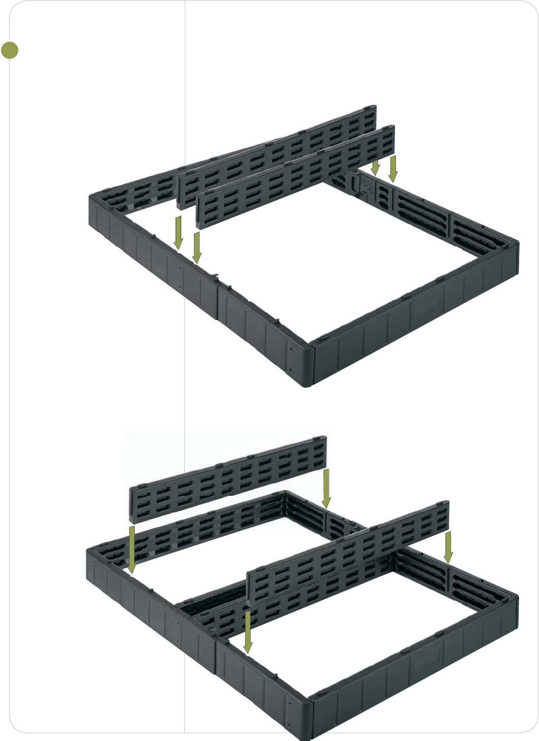
4INSERT SUPPORT
BEAMS
Tabs up, match “A” end with
“A” groove; match “B” end
with “B” groove.
Joints fi t tightly, push fi rmly
until top is fl ush.
Slide the remaining
support beams into the
next set of channels.
A
B
A
B
h
e
A
B
A
B
8
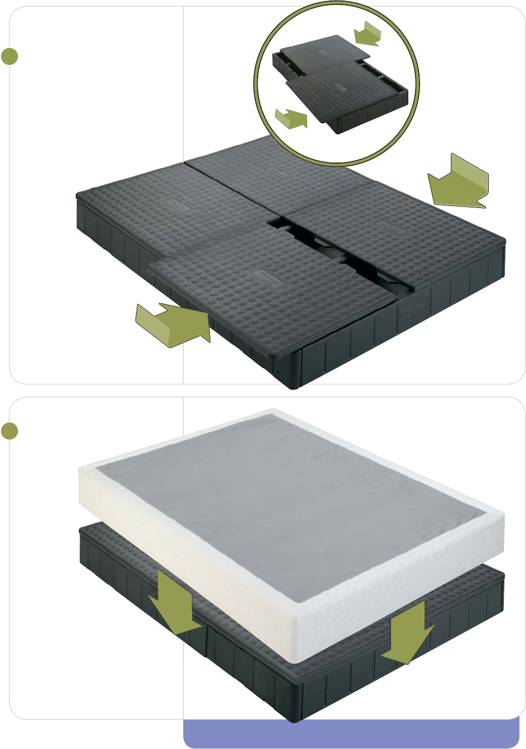
5PLACE DECK PANELS
Slide panels in until they are
fl ush on sides.
Panels fi t snugly, do not force.
Queen shown
Reminder
King foundation
consists of two
Twins side by side.
6PUT ON COVERLET
Work on carefully, one
corner at a time, position
seam at head of bed.
Expanded Queen coverlet will
go over the corner brackets.
9
Twin shown
YOU’RE DONE! NEXT STEP X MATTRESS ASSEMBLY

Foundation
Frequently
Asked Questions
Make sure the letter on the center support beam matches the side rail.
For example, the end of the center beam labeled “A” should connect
to the side rail with the “A” on it. Additional force may be required.
What if I can’t get my
center support beams
fl ush with the side rails?
How can I get my pins
in all the way?
All pins are wider at one end and narrower at the other end. Make
sure the “T” end is up and the narrow end goes into the side rail fi rst.
You may need to use a bit of force to get it in place.
What can I do if I can’t
get the deck panels to
lay fl at?
First, make sure all the pins and beams are fl ush. Then, set the deck
panel over the notches. You should then be able to slide the panel
into place.
Where is the hardware
for the footboard and
headboard brackets?
The same hardware for attaching the legs to the foundation is used for
attaching the brackets. Align the bracket with the holes for the leg bolts.
Attach the leg per the instructions.
10
If you still have questions or need assistance, look for answers on our Web site
sleepnumber.com or please call Customer Service at 1.800.472.7185
Mattress
Assembly
11

Mattress
Assembly
12
BEFORE YOU BEGIN
X Carefully check the contents of your mattress boxes
XIMPORTANT NOTE Prepare your foam pad(s)
If you purchased a bed with foam comfort pad(s), carefully open
the pad(s) and set aside.
At least 20 minutes of expansion time is needed.
X Orientation
These instructions refer to “left” and “right” as if you are standing
at the head of the bed looking toward the foot of the bed.
X Using a Surge Protector
While the Firmness Control™ System may be plugged directly into
a wall outlet, we recommend using a surge protector to guard
against unexpected power surges. We recommend using a surge
protector that is listed to UL® 1449 with a clamping voltage of
330 volts, and a joule rating of 700 or higher.
Please note: Your 20-Year Limited Warranty does not cover damage
to the Firmness Control™ System due to a power surge, regardless
of the source. See the Limited Warranty on page 37 for more details.
If you are missing any items
listed on the following page,
please e-mail Customer
Service at customerservice@
selectcomfort.com or call
1.800.472.7185
TROUBLESHOOTING
For answers to some common
questions regarding your
mattress, see the Frequently
Asked Questions at the end
of this section.
“ This is the fi rst time in three
years that I slept through the
entire night without getting up
two or three times. I’m thrilled
and amazed! Unbelievable! I wish
we had purchased your sleeping
system years ago. ”
- Keith Fisher, Jackson, MI
CONTENTS
Carefully check the contents of your mattress boxes
and compare with the list below. Each component is
clearly labeled with the part name and part number.
Mattress Cover
Color and pattern will
vary by model
Shown as packaged
Foam Border Walls
Two long and two short
Shown as packaged
Corner Lock™
System
Shown as packaged
Air Chambers
Firmness Control™
System with Remotes
Remotes will vary
Center Foam Wall
Dual Chamber models only
Single Chamber Dual Chamber
1 1 1 1
4 4 4 4
4 4 4 4
1 1 2 2
1 1 1 1
0 0 1 1
1 1 1 1
Foam
Comfort Pad
Color and
pattern may vary
Shown as packaged
QUANTITY
13
Twin Full/Queen Dbl/Queen King
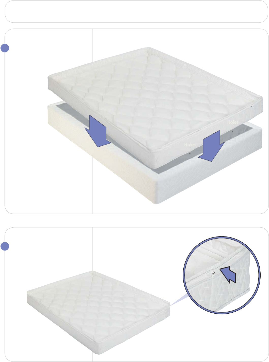
1
2UNZIP MATTRESS
COVER
Set cover aside.
14
POSITION MATTRESS
COVER
Place on foundation
or on existing
bed platform.
Make sure the holes
in the bottom of the cover
are at the head of the bed.
)PMFT
)PMFT
REMEMBER: Open the foam comfort pad(s) before you begin and let expand for 20 minutes.
Foot
Head
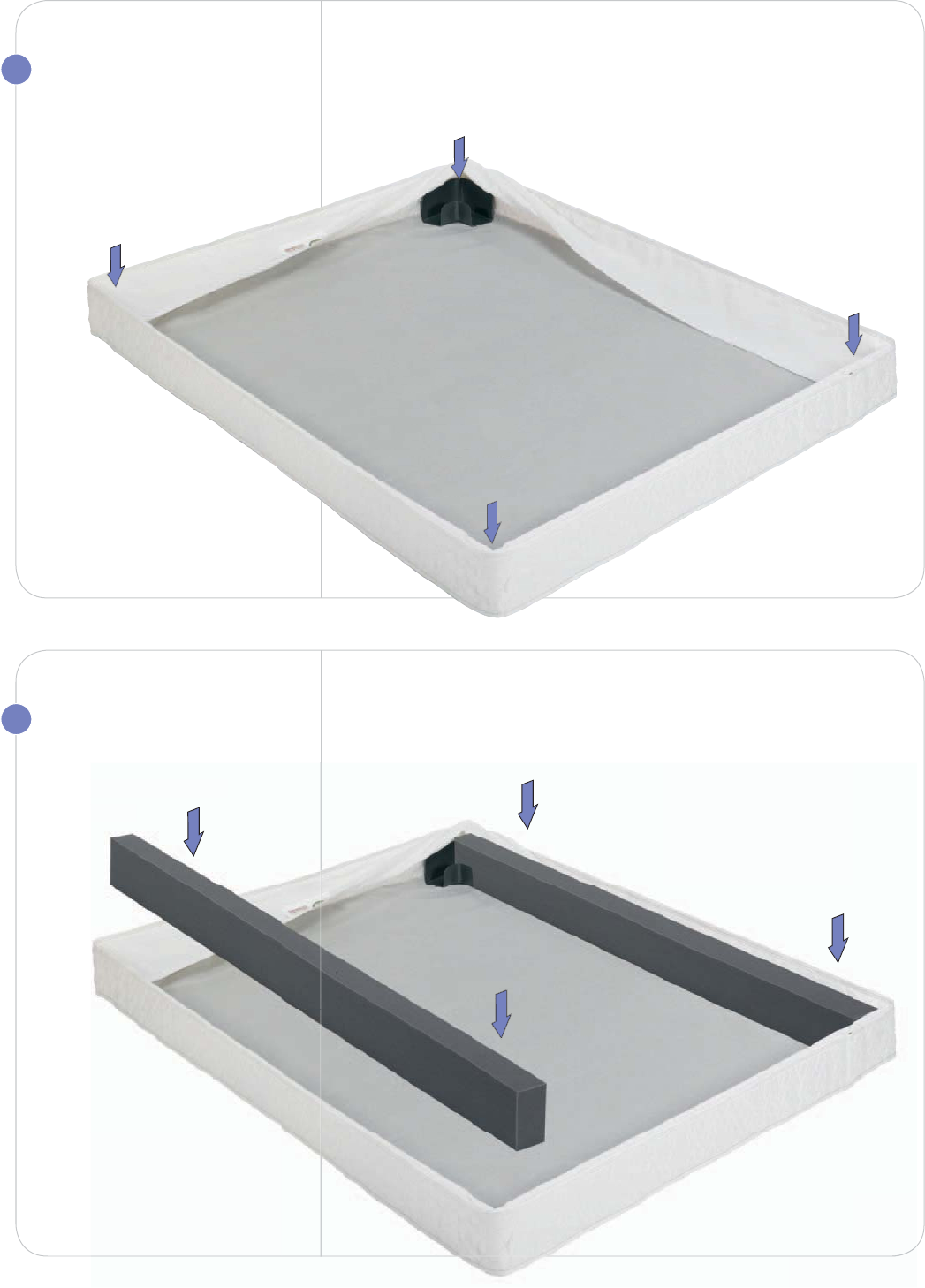
3
4
15
PLACE CORNER
LOCKS
Place one in each corner.
Corner locks must go under
the border wrap.
INSTALL FOAM
BORDER WALLS
Place long border walls
along sides.
long border walls
si
d
es
.
16
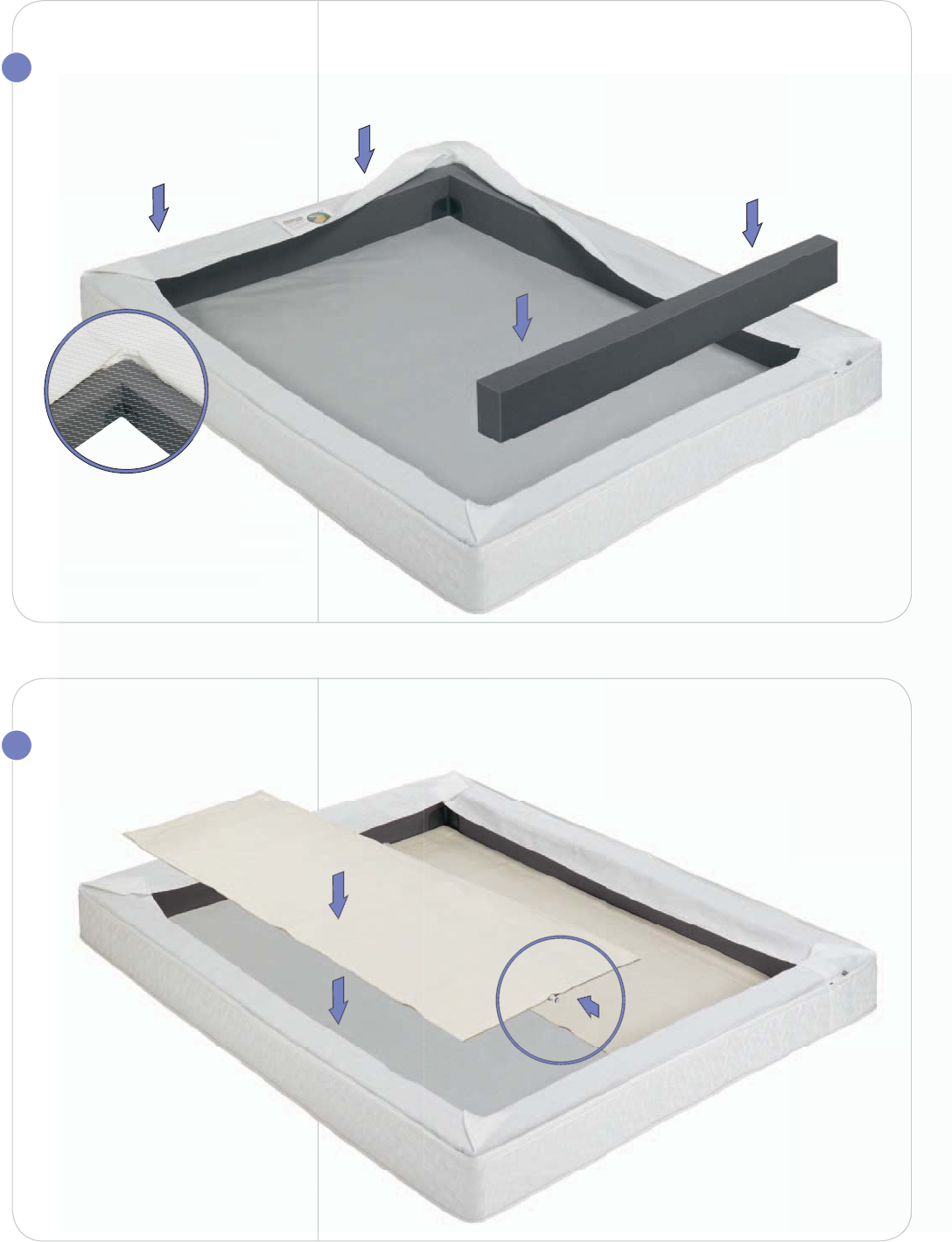
5INSTALL FOAM
BORDER WALLS
Place short border walls at the
head and foot.
Make sure the foam border
walls are connected securely and
squarely. The border wrap should
cover the foam border walls.
6INSTALL AIR
CHAMBERS
Place air chambers so the
hose connectors face the
head of the bed, and lay on
bottom when infl ated.
Dual chambers shown
NSTALL FOAM
O
RDER WALL
S
a
ce short border walls at the
ead a
n
d
f
oo
t
.
a
ke sure the foam border
all
s are connecte
d
secure
l
y an
d
q
uarel
y
. The border wrap should
o
v
e
r
t
h
e foa
m
bo
r
de
r w
a
ll
s
.
Foot
Head
7
17
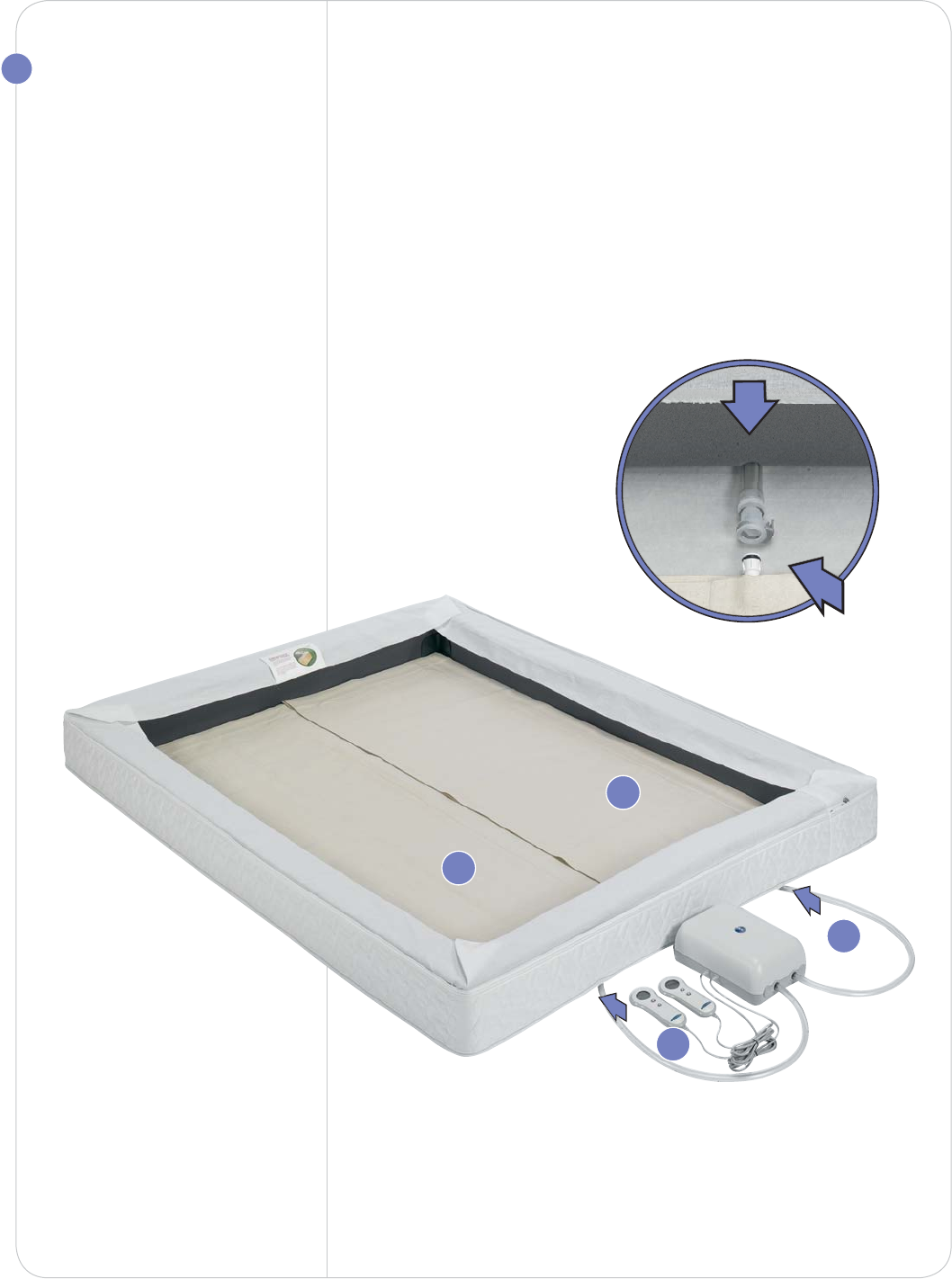
CONNECT FIRMNESS
CONTROL™ SYSTEM
Place the Firmness Control™
System on the fl oor at the
head of the bed and plug in
the power cord.
For the Sleep Number® 5000
Bed you will also need to plug
the power cord into the
Firmness Control™ System.
Key Step:
Pass the hose marked ”L”
through the hole on the left
side of the mattress cover and
connect to the left air chamber.
Press hose connections
together until they click.
Then complete the right side.
L
L
R
R
Foot
Head
18
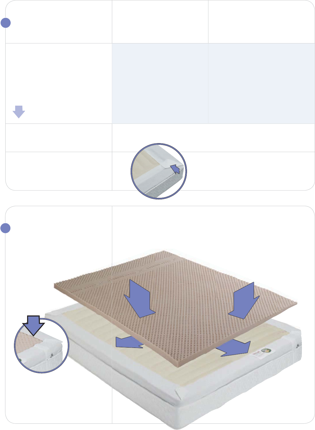
9INSTALL FOAM
COMFORT PAD
Carefully shake out pad.
Place the Intralux® foam
comfort pad on top
of the air
chambers.
Make sure the patterned side
is up. Then extend the border
wrap over the Intralux® foam
comfort pad.
Foam color and pattern may vary.
INFLATE AIR
CHAMBER(S)
Using remote, infl ate air chamber.
For dual chamber models,
repeat for second air chamber.
Insert center foam wall
between the two chambers.
Position the border wrap
over foam border walls and air
chambers as shown.
Sleep Number®
4000 Bed
Press L or R to activate
and select a side.
Press and hold the fi rmer
button to begin infl ating
the mattress.
Sleep Number®
5000 Bed
Press any button on the
remote to activate.
For wireless remotes, press L or R
to activate and select a side.
Press the button several
times to infl ate to 20. Adjustments
will begin after a slight delay.
8