SmartAnt Telecom SAA04052240 RANGE EXTENSION WLAN ADAPTER User Manual manual saa04 052240
SmartAnt Telecom Co., Ltd. RANGE EXTENSION WLAN ADAPTER manual saa04 052240
Contents
- 1. USERS MANUAL 1
- 2. USERS MANUAL 2
USERS MANUAL 1
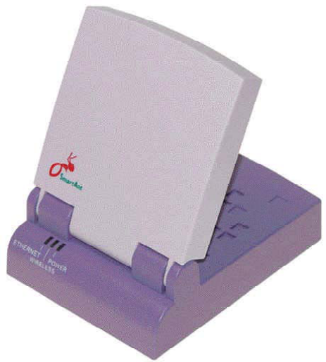
SmartAnt High Gain Ethernet Adapter
for 802.11 b/g
(SAA04-05224A,SAA04-05224A-05224A-EU)
User’s Manual

2SmartAnt
Federal Communications Commission Statement
This device complies with Part 15 of the FCC Rules. Operation is subject to the
following two conditions:
• This device may not cause harmful interference, and
• This device must accept any interference received, including interference
that may cause undesired operation.
This equipment has been tested and found to comply with the limits for a
class B digital device, pursuant to Part 15 of the Federal Communications
Commission (FCC) rules. These limits are designed to provide reasonable
protection against harmful interference in a residential installation. This
equipment generates, uses, and can radiate radio frequency energy and, if
not installed and used in accordance with the instructions, may cause
harmful interference to radio communications. However, there is no
guarantee that interference will not occur in a particular installation. If this
equipment does cause harmful interference to radio or television reception,
which can be determined by turning the equipment off and on, the user is
encouraged to try to correct the interference by one or more of the following
measures:
• Reorient or relocate the receiving antenna.
• Increase the separation between the equipment and receiver.
• Connect the equipment into an outlet on a circuit different from that to
which the receiver is connected.
• Consult the dealer or an experienced radio/TV technician for help.
WARNING! The use of a shielded-type power cord is required in or-
der to meet FCC emission limits and to prevent interference to the
nearby radio and television reception. It is essential that only the
supplied power cord be used. Use only shielded cables to connect I/
O devices to this equipment. You are cautioned that changes or
modifications not expressly approved by the party responsible for
compliance could void your authority to operate the equipment.
Reprinted from the Code of Federal Regulations #47, part 15.193, 1993.
Washington DC: Office of the Federal Register, National Archives and
Records Administration, U.S. Government Printing Office.
Canadian Department of Communications
This digital apparatus does not exceed the Class B limits for radio noise
emissions from digital apparatus set out in the Radio Interference
Regulations of the Canadian Department of Communications.
This Class B digital apparatus complies with Canadian ICES-003. Cet
appareil numérique de la classe B est conforme à la norme NMB-003
du Canada.
Notices

SmartAnt 3
FCC Radio Frequency Exposure Caution Statement
In order to maintain compliance with the FCC RF exposure guidelines, this
equipment should be installed and operated with minimum distance 20cm
between the radiator and your body. Use only with supplied antenna.
Unauthorized antenna, modification, or attachments could damage the
transmitter and may violate FCC regulations. Any changes of modifications
not expressly approved by the grantee of this device could void the users
authority to operate the equipment.
Installation and use of this Wireless LAN device must be in strict accordance
with the instructions included in the user documentation provided with the
product. Any changes or modifications (including the antennas) made to
this device that are not expressly approved by the manufacturer may void
the user’s authority to operate the equipment. The manufacturer is not
responsible for any radio or television interference caused by unauthorized
modification of this device, or the substitution or attachment of connecting
cables and equipment other than manufacturer specified. It is the
responsibility of the user to correct any interference caused by such
unauthorized modification, substitution or attachment. Manufacturer and
its authorized resellers or distributors will assume no liability for any damage
or violation of government regulations arising from failing to comply with
these guidelines.
This device and its antenna(s) must not be co-located or operating
in conjunction with any other antenna or transmitter.
Declaration of Conformity (R&TTE directive 1999/5/EC)
The following items were completed and are considered relevant and sufficient:
• Essential requirements as in [Article 3]
• Protection requirements for health and safety as in [Article 3.1a]
• Testing for electric safety according to [EN 60950]
• Protection requirements for electromagnetic compatibility in [Article 3.1b]
• Testing for electromagnetic compatibility in [EN 301 489-1] & [EN 301]
• Testing according to [489-17]
• Effective use of the radio spectrum as in [Article 3.2]
• Testing for radio test suites according to [EN 300 328-2]
Notices

4SmartAnt
Table of Contents
1.1 Welcome! ....................................................................................... 5
1.2 Package contents .......................................................................... 5
1.3 Features ........................................................................................ 6
1.3.1 Top view ................................................................................ 6
1.3.2 Bottom view .......................................................................... 7
1.3.3 Rear view .............................................................................. 7
1.4 LED indicators ............................................................................... 8
1.5 Recommended network settings.................................................. 9
1.5.1 Access Point mode .............................................................. 9
1.5.2 Ethernet adapter mode ....................................................... 10
2.1 System requirements .................................................................. 13
2.2 Device installation ....................................................................... 13
2.2.1 Before you proceed ............................................................ 13
2.2.2 Using DC power ................................................................. 14
2.2.3 Using USB bus power........................................................ 15
2.3 Placement.................................................................................... 16
Wall mounting................................................................................ 16
2.4 Operating range ........................................................................... 16
2.4.1 Range ................................................................................. 16
2.4.2 Site survey .......................................................................... 17
2.5 Roaming information................................................................... 17
3.1 Installing the utilities.................................................................... 18
3.2 Wireless Setting Utility................................................................. 19
3.2.1 Launching the Wireless Setting Utility ............................... 19
3.2.2 Using the Wireless Setting Utility ....................................... 20
3.3 Web Configuration utility .............................................................. 26
3.3.1 Adjusting the TCP/IP settings............................................. 26
3.3.2 Launching the Web Configuration utility ............................. 28
3.3.3. Changing the access point (AP) configuration ................... 29
3.3.4 Changing the Ethernet adapter configuration .................... 39
3.4 Firmware Restoration ................................................................. 52
4.2 Replacing the computer Ethernet cables .................................... 53
4.3 Replacing cable connections of other devices ........................... 54
4.4 Sharing Internet connection with other PCs................................ 54

SmartAnt 5
1. Product introduction
1.1 Welcome!
Thank you for choosing the SmartAnt SAA04-05224A series. This manual can
use for SAA04-05224Aand SAA04-05224A-EU. ( mention as SAA04-05224A
in following chapters. ) The SmartAnt SAA04-05224A is a compact easy-to-
install Ethernet adapter. Implementing the IEEE 802.11g standard for wireless
LAN (WLAN), the SmartAnt SAA04-05224A is capable of up to 54Mbps data
transmission rate using the Direct Sequence Spread Spectrum (DSSS) and the
Octogonal Frequency Division Multiplexing (OFDM) technologies.
The SmartAnt SAA04-05224Asupports Infrastructure and Ad-hoc modes giving
you flexibility on your existing or future wireless network configurations.
To provide efficient security to your wireless communication, SmartAnt SAA04-
05224Acomes with a 64-bit/128-bit Wired Equivalent Privacy (WEP) encryption
and Wi-Fi Protected Access (WPA) features.
With these and many more, SmartAnt SAA04-05224A is sure to keep you ahead
in the world of wireless computing.
1.2 Package contents
Check the following items in your SmartAnt SAA04-05224A package. Contact
your retailer if any item is damaged or missing.
High gain Ethernet adapter
Power adapter
RJ-45 cable
USB Cable
Mounting set
Utility CD
Quick Installation Guide
Unless otherwise specified, the term “ddevice” in this User Guide
refers to the SmartAnt SAA04-05224A.
6SmartAnt
1.3 Features
The SmartAnt SAA04-05224A employs the DSSS and OFDM technologies to
transmit and receive signals through radio waves on the 2.4 GHz band.
Here are other SmartAnt SAA04-05224A features:
• Reliable data transfer rates of up to 54Mbps
• Secure data transmission via Wired Equivalent Privacy (WEP) and WiFi
Protected Access (WPA) encryptions
• Operating distance of up to 260ft (80m) indoors and 2000 ft (620m) outdoors
• Equipped with mounting set for window mount and wall installation
• Dual power mode (DC or USB bus-powered)
•Windows
®2000/XP compatible
1.3.1 Top view
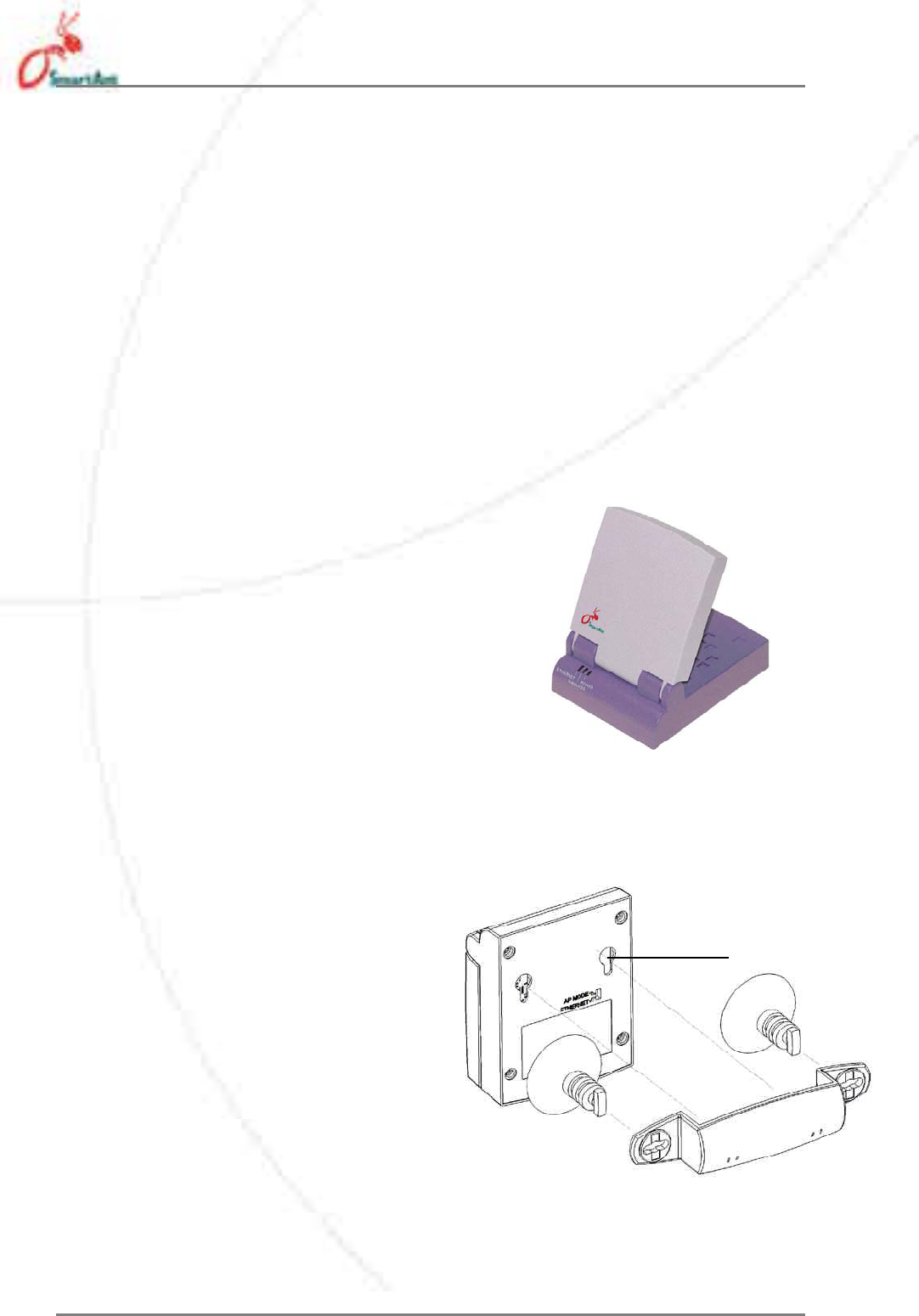
LEDs. The SmartAnt SAA04-05224A comes
with three LED indicators (Ethernet, Wireless,
and Power).
1.3.2 Bottom view
Mounting hook. Use the mounting
hook to install the device on
concrete or wooden surfaces using
a roundhead screw.
1. Product introduction
Mounting
hole
Air vents. These vents provide ventilation to
the device.
Status Indicators
SmartAnt 7
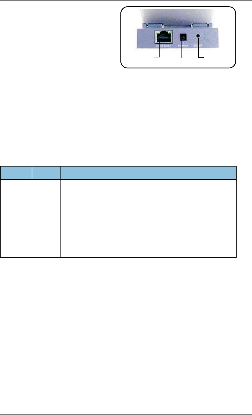
1.3.3 Rear view
Ethernet port. This port connects the
supplied RJ-45 plug and cable.
Power socket. This socket connects
the power adapter plug.
Reset button. Press this button for
more than five seconds to load the default values. In Ethernet adapter mode,
press this button for less than five seconds to connect to the first saved wireless
connection in the profile table.
Ethernet port DC IN socket Reset button
1. Product introduction
1.4 LED indicators
The SmartAnt SAA04-05224A comes with a Ethernet, Wireless, and
Power LED indicators. Refer to the table below for LED indications.
LED Status Indication
Ethernet On
The device is connected to an Ethernet network.
Off
The device is off or not connected to an Ethernet network.
Wireless On
The device is associated with an AP or other wireless device.
Off
The device is not associated with an AP or other wireless device.
Blinking
The device is transmitting or receiving data.
Power On
Thedeviceisonandready.
Off
The device is off or performing boot sequence.
Blinking
Firmware upgrade failed.
8SmartAnt
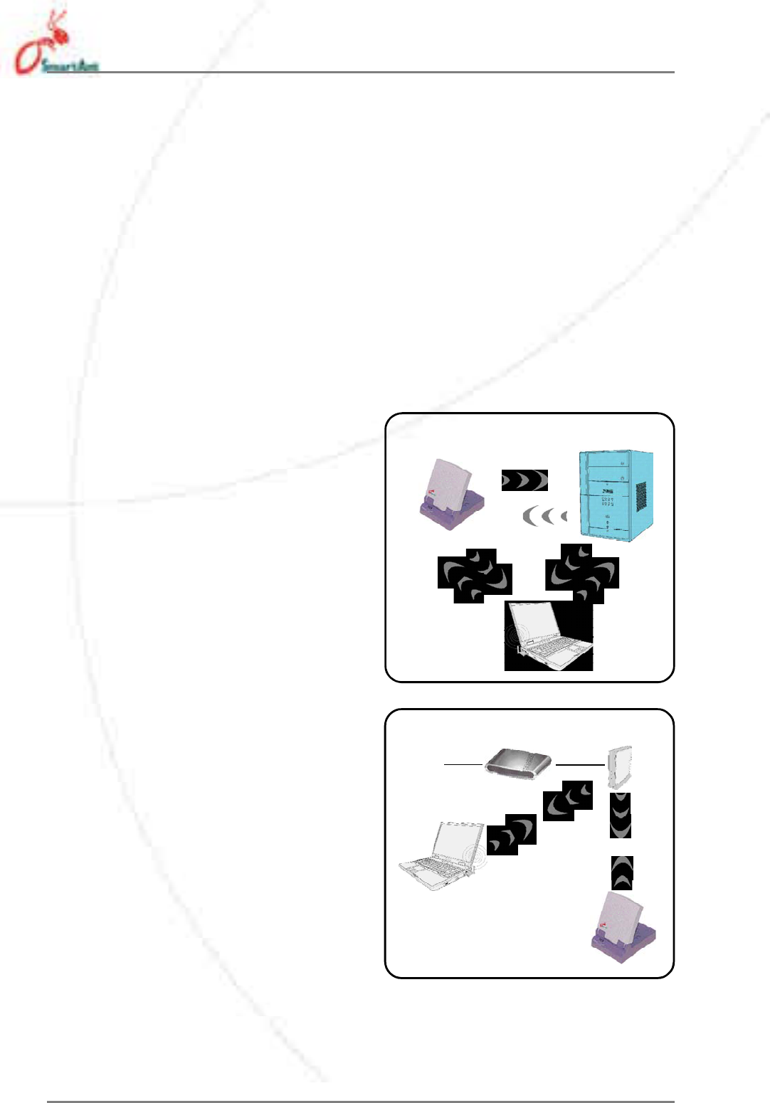
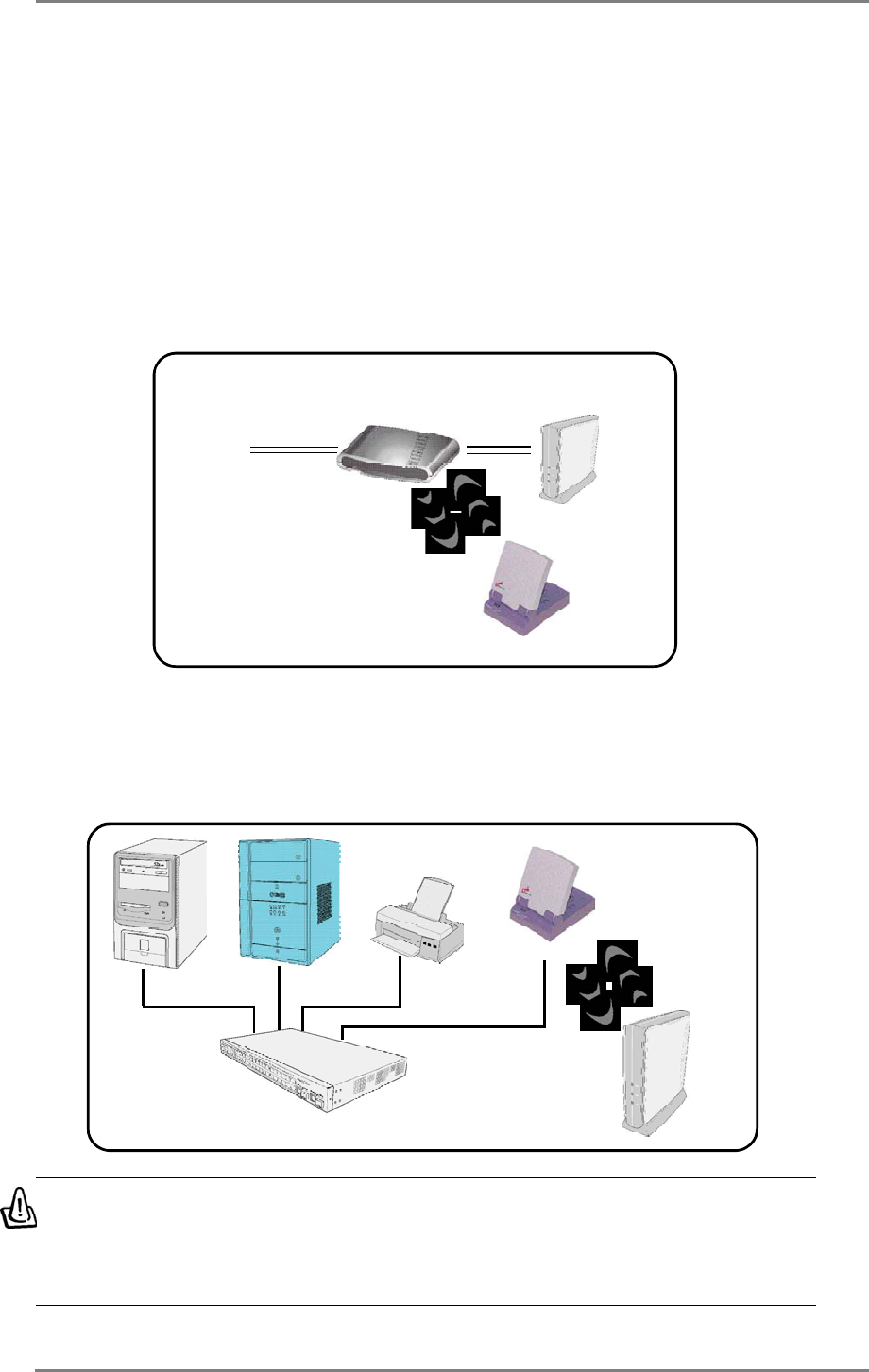
Infrastructure mode
When in Infrastructure mode, the
wireless network is centered on an
access point (AP) that provides a
central link for wireless clients to
communicate with each other or with
a wired network.
In this setup, the SmartAnt SAA04-
05224A connects to an AP using a
single or multiple IP to establish
connection to a wired or wireless
LAN.
1.5.1 Ethernet adapter mode
Ad-hoc network
When in Ad-hoc network, the
SmartAnt SAA04-05224A connects
to another wireless device. No
access point (AP) is present in this
wireless environment.
1.5 Recommended network settings
The SmartAnt SAA04-05224A can be configured as a wireless Ethernet
adapter. In Ethernet adapter mode, the device connects to:
1. A wireless device(s) (Ad-hoc mode), or
2. An access point (Infrastructure network type)
Determine your network settings before installing the SmartAnt SAA04-
05224A. The following network settings are recommended.
1. Product introduction
Station1
Station2
Internet ADSLModem AccessPoint
Station1
SmartAnt 9
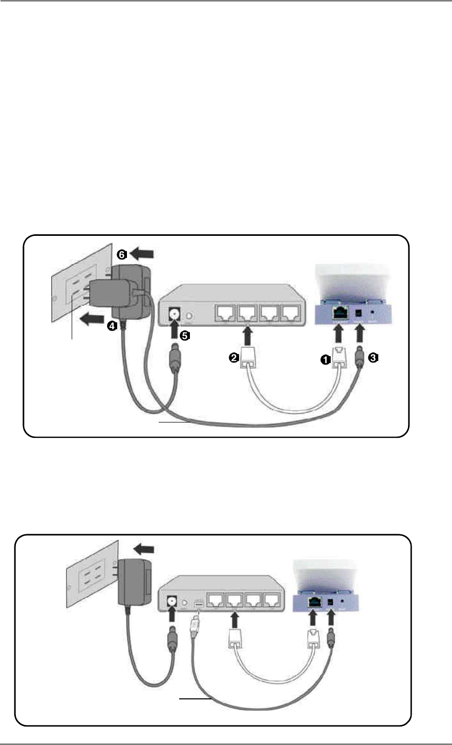
Multiple IP bridge environment
In a multiple IP bridge environment, the SmartAnt SAA04-05224A connects
two or more wired devices to a wireless network from a hub or a switch.
Single IP bridge environment
In a single IP bridge environment, the SmartAnt SAA04-05224A connects
to an access point using a single IP address.
In this setup, the MAC cloning feature may be enabled to support certain
applications and devices, such as Xbox and PlayStation® game consoles,
that use the MAC address to communicate with other devices. MAC
cloning allows the SmartAnt SAA04-05224A to communicate with other
devices in a wireless network using the MAC address of the host computer
instead of its own.
Hub
Accesspoint
You must disable the MAC cloning feature when you set the device in
Ethernet adapter mode under this environment. Enabling MAC clon-
ing under this environment results to undefined and incorrect bridge
behavior.
1. Product introduction
Internet ADSLModem AccessPoint

10 SmartAnt
2. Hardware installation
2.1 System requirements
Before installing the SmartAnt SAA04-05224A, make sure that your
system/network meets the following requirements:
• An Ethernet RJ-45 port (10Base-T/100Base-TX)
• At least one IEEE 802.11b/g device with wireless capability
• An installed TCP/IP and Internet browser
2.2 Device installation
Follow these instructions to install the SmartAnt SAA04-05224A.
1. Install the device utilities from the support CD.
2. Connect the device to your computer, network hub, switch, or router.
2.2.1 Before you proceed
Take note of the following guidelines before installing the SmartAnt SAA04-
05224A.
• The length of the Ethernet cable that connects the device to the network
(hub, ADSL/cable modem, router, wall patch) must not exceed 100
meters.
• Place the device on a flat, stable surface as far from the ground as
possible
• Keep the device clear from metal obstructions and away from direct
sunlight.
• Keep the device away from transformers, heavy-duty motors, fluorescent
lights, microwave ovens, refrigerators, and other industrial equipment
to prevent signal loss.
• Install the device in a central area to provide ideal coverage for all
wireless mobile devices.
• Install the device at least 20cm from a person to insure that the product
is operated in accordance with the RF Guidelines for Human Exposure
adopted by the Federal Communications Commission.
SmartAnt 11
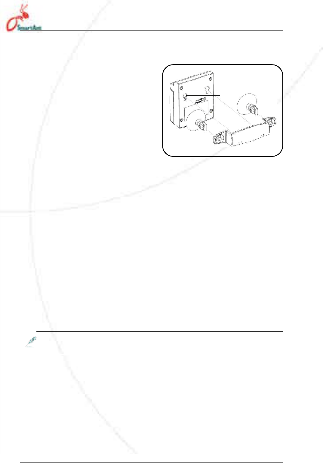
2.2.3 Using USB bus power
Replace the AC-DC power cable with a USB power cable and insert into
an available USB port on any device (computer, notebook, network hub,
switch, or router) and turn ON that device.
2.2.2 Using DC power
1. Insert one end of the supplied RJ-45 cable to the SAA04-05224A
Ethernet port.
2. Insert the other end of the RJ-45 cable to a network hub, switch,
router, or wall patch Ethernet port.
3. Connect the power adapter plug to the SAA04-05224A Power socket.
4. Connect the SAA04-05224A power adapter to a wall socket.
5. Connect the network hub, switch, or router power adapter plug to the
Power socket of the device.
6. Connect the network hub, switch, or router power adapter to a wall
socket.
2. Hardware installation
NetworkDevice
Wallsocket
AC-DCpowercable
NetworkDevicewithUSB
USBpowercable
12 SmartAnt
2.3 Placement
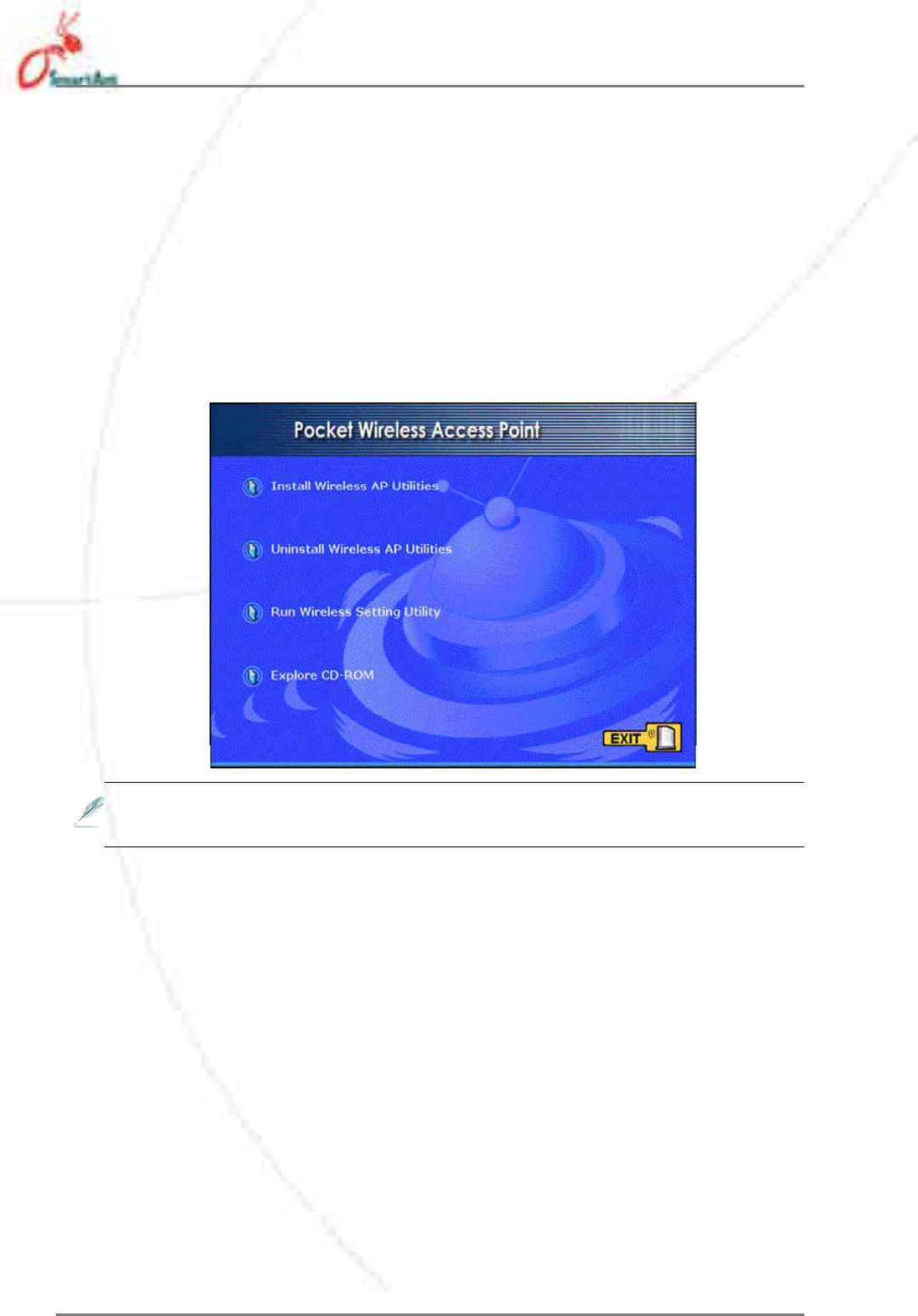
Wall mounting
Aside from desktop placement, you
can install the SmartAnt SAA04-
05224A vertically on a wall using the
mounting hook at the bottom side
of the device.
To mount the device on a wall:
1. Tighten a screw on the wall until
only 1/4 inch is showing.
2. Latch the mounting hook on the screw.
Adjust the screw if you cannot latch the device or if the device is too
loose.
2. Hardware installation
Mountinghook
Window mounting
Using the window mount sets, SmartAnt SAA04-05224A can be installed
on flat window class, and receive wireless signals from either side of the
window.
Tomountthedeviceonawindowclass:
1. Compose window mount set. Reverse the suck discs, if the signal is
from the other side of the window.
2. Compose the window mount set on the middle of the bottom of the
device.
3. Press both suck discs onto the window class. Make sure the device
does not fall before leave you hands.

SmartAnt 13
2.4 Operating range
2.4.1 Range
The SmartAnt SAA04-05224A range is dependent on the operating
environment. Every home or office layout varies in obstacles, barriers, or
wall types which may reflect or absorb radio signals. For example, two
802.11b devices in an open space may achieve an operating distance of
up to 1000 meters, ( 3280 feet ) while the same devices may only achieve
up to 300 ( 984 feet ) meters of range when used indoors.
The device automatically adjusts the data rate to maintain an operational
wireless connection. A wireless device that is close to an AP may operate
at higher speeds than a device far from the AP. You can configure the
data rates that a device uses. If you limit the range of data rates available
to the an AP, you may reduce the effective range of the wireless LAN
coverage.
2.4.2 Site survey
A site survey (utility provided with the SmartAnt SAA04-05224A) analyzes
the installation environment and provides users with recommendations
for equipment and its placement. The optimum placement differ depending
on the device design and specifications.
14 SmartAnt
3. Configuration
3.1 Installing the utilities
The support CD contains the utilities for configuring the SmartAnt SAA04-
05224A.
To install the device utilities in your computer:
1. Insert the support CD to the optical drive.
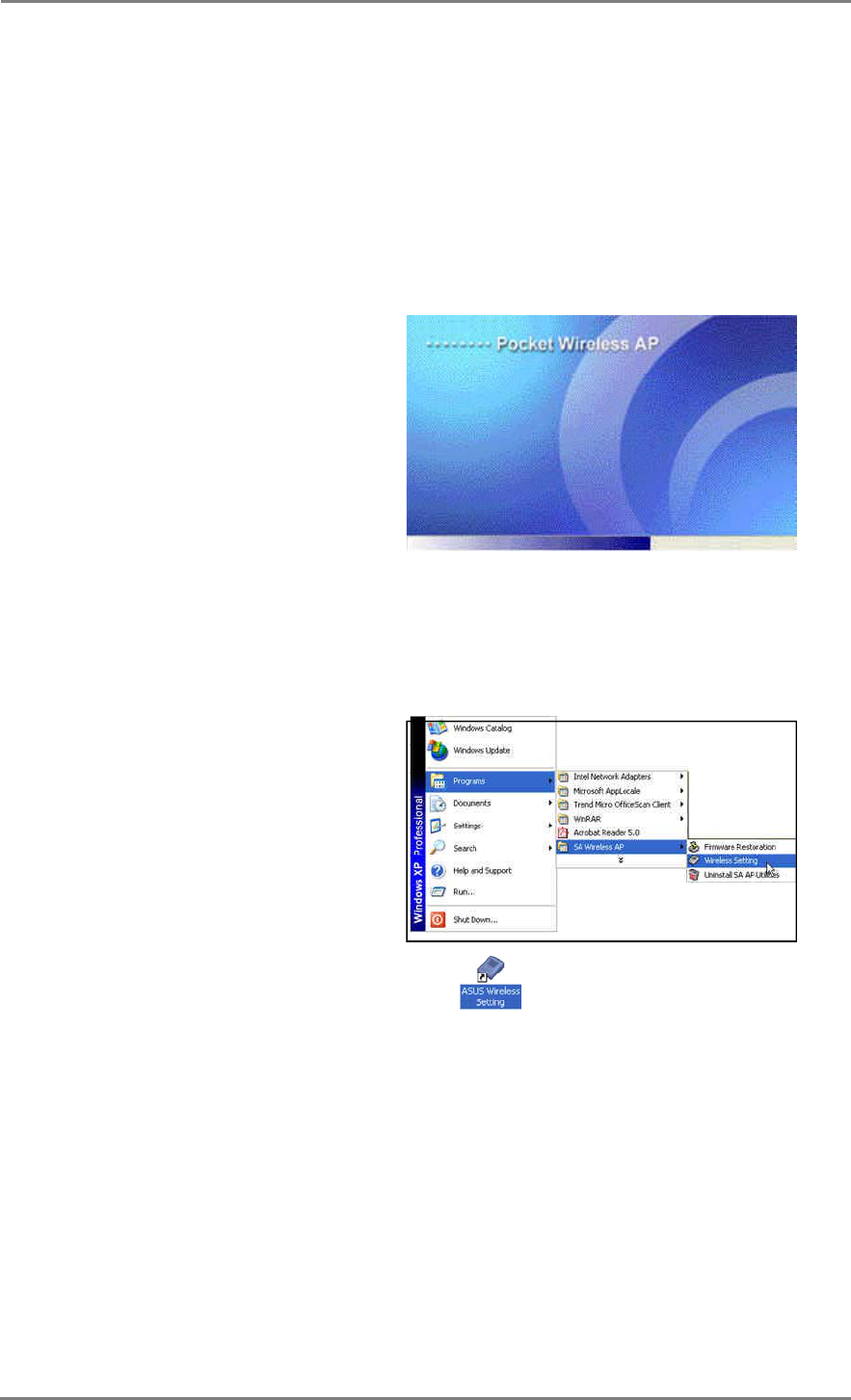
2. Click Install Wireless AP Utilities when the Wireless Access
Point SAA04-05224A installation window appears.
3. The device utilities are copied to your computer.
Other support CD options
Uninstall WLAN AP Utilities. Click this option to uninstall the
SmartAnt SAA04-05224A utilities from your system.
Run Wireless Setting Utility. Click this option to run the Wire-
less Setting Utility.
Explore this CD. Click this option to explore the support CD con-
tents & User Manual in PDF.
Click EXIT to close the installation window.
If Autorun is NOT enabled in your computer, browse the contents of
the support CD and double click the Setup.exe file to run the CD.
SmartAnt 15
3.2 Wireless Settings Utility
The Wireless Settings Utility allows easy configuration of the SmartAnt SAA04-
05224A. You can launch the Wireless Settings Utility directly from the support
CD or from the Windows®desktop.
3.2.1 Launching the Wireless Settings Utility
From the support CD
To launch the Wireless Settings Utility
from the support CD:
1. Insert the support CD to the optical
drive.
2. Click the Run Wireless Settings
Utility option when the installation
window appears. Refer to the illustration on the previous page.
3. The Wireless Settings Utility window appears.
From the Windows®desktop
1. Install the device utilities.
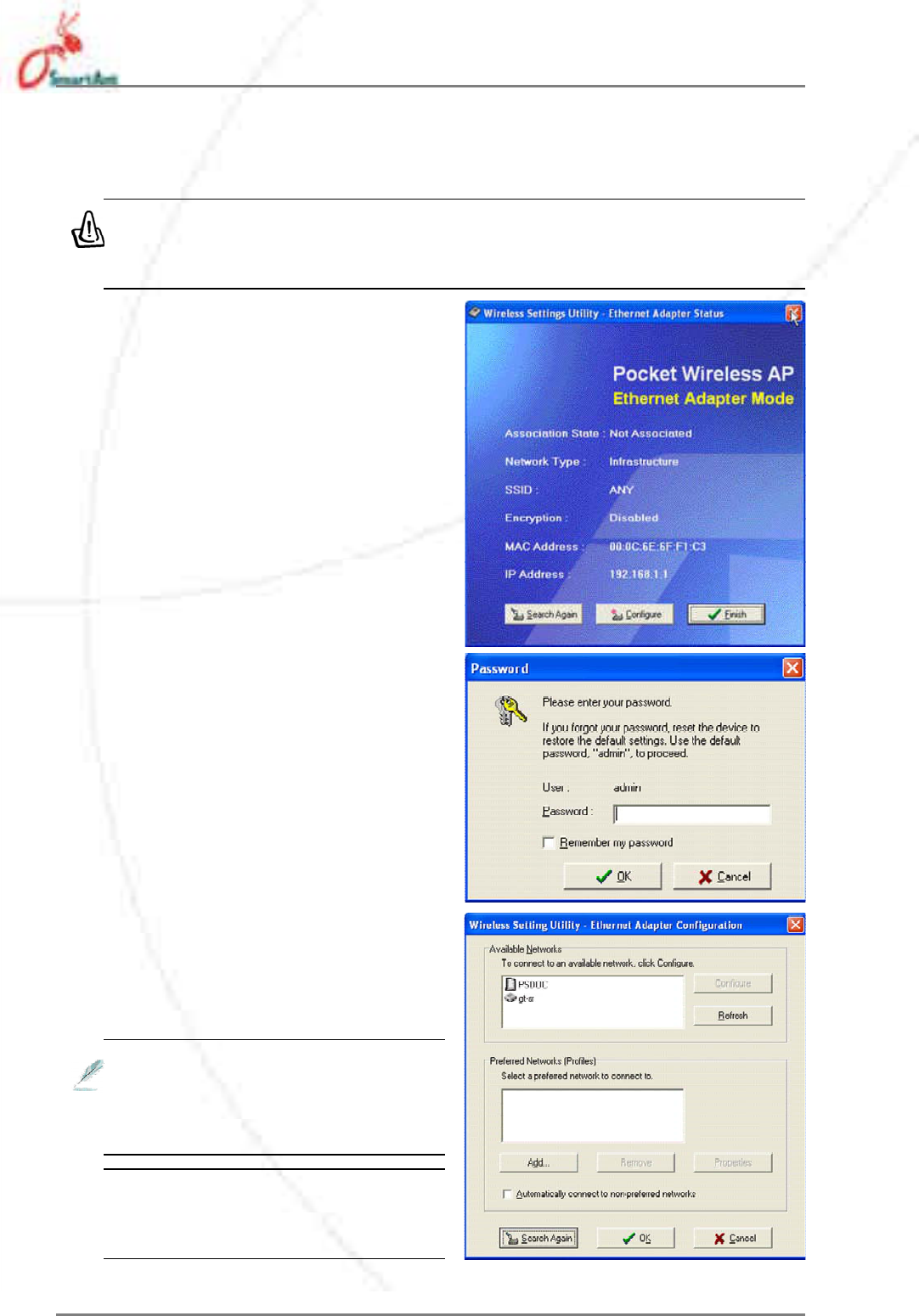
2. From the Windows®desktop, click
Start >All Programs >
Wireless AP >Wireless Setting.
or
Double-click the Wireless Setting icon.
3. The Wireless Setting Utility window appears.
3. Configuration
16 SmartAnt
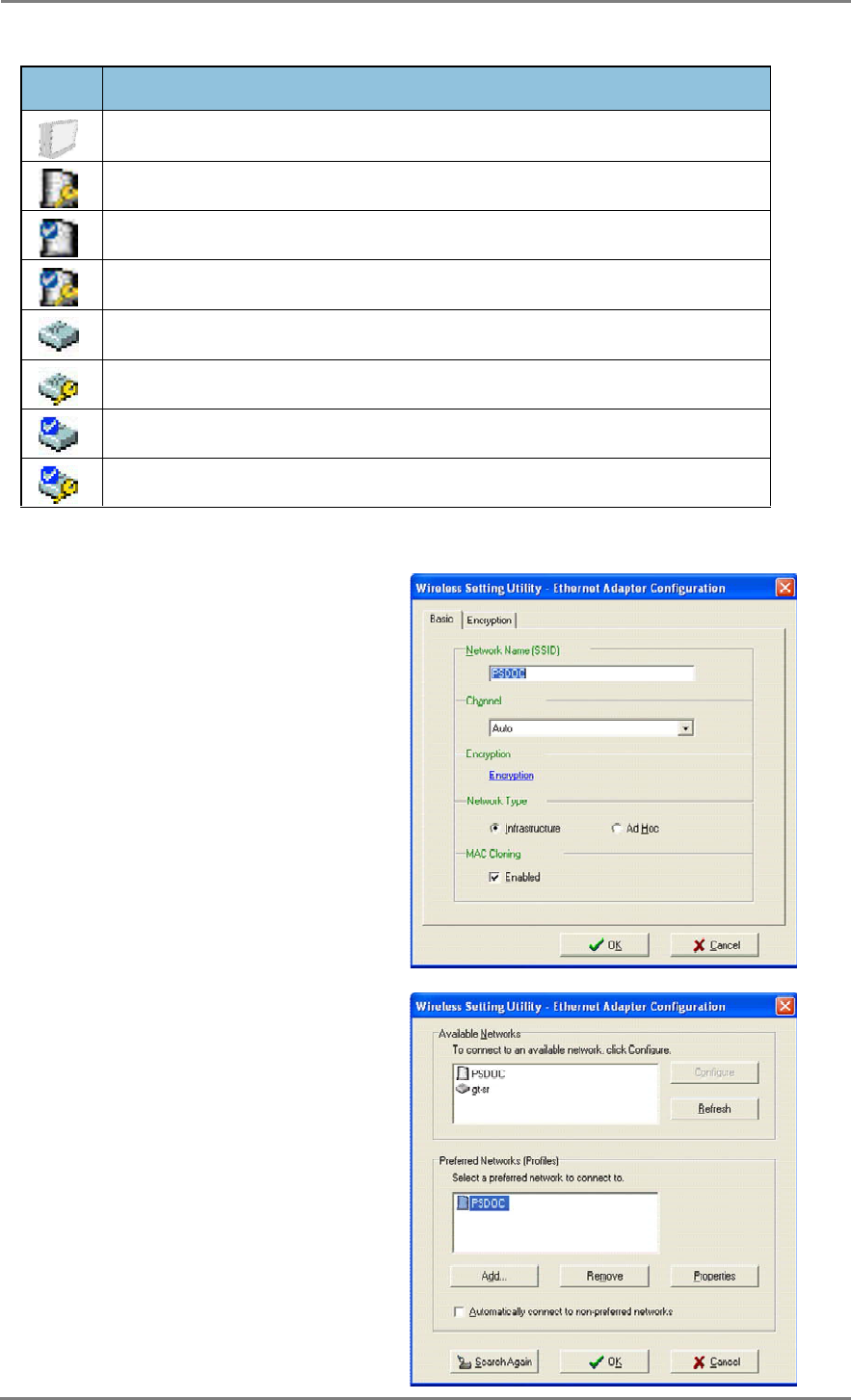
1. The utility auto-detects and
displays the SAA04-05224A
Ethernet adapter settings. Click
Configure to continue.
2. Log on to the configuration
window using the password
(admin), check the Remember
my password option, then click
OK.
To set the device as an Ethernet adapter
Make sure that you switched the SAA04-05224A to Ethernet adapter
mode before launching the Wireless Setting Utility. Use the mode
switch to change the device operating mode.
3. Select a wireless network from
the Available Networks field,
then click Configure.
Each wireless network is pre-
ceded by an icon for easy identifi-
cation. Refer to the table on the
next page for icon indications.
Click Add to connect to another
wireless network not listed in the
field.
3. Configuration
3.2.2 Using the Wireless Settings Utility
SmartAnt 17
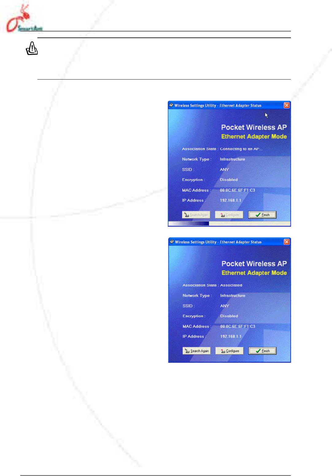
5. The selected wireless network
appears in the Preferred
Networks field. Select the
network, then click OK.
4. The SAA04-05224A
automatically adjusts to the
SSID and channel settings of the
selected wireless network. Click
OK.
Icon Indicates that
thewirelessnetworkisanaccesspointwithnoencryption
thewirelessnetworkisanaccesspointwithenabledencryption
theSAA04-05224Aisconnectedtothisaccesspointwithnoencryption
theSAA04-05224Aisconnectedtothisaccesspointwithenabledencryption
thewirelessnetworkisawirelessdevicewithnoencryption
thewirelessnetworkisawirelessdevicewithenabledencryption
theSAA04-05224Aisconnectedtothiswirelessdevicewithnoencryption
theSAA04-05224Aisconnectedtothiswirelessdevicewithenabledencryption
Table 3-1: Wireless network icon indications
3. Configuration
18 SmartAnt
6. The SAA04-05224A connects to
the selected wireless network.
7. The utility displays the SAA04-
05224A status when connection
is established. Click Finish to
close the utility.
If the selected network has enabled encryption, use the Encryption
tab to set the SAA04-05224A encryption settings the same with the
selected network. The encryption settings of the network and the
SAA04-05224A must be the same to establish connection.
3. Configuration
SmartAnt 19
3.3 Web Configuration utility
The Web Configuration utility allows you to configure the SmartAnt SAA04-
05224A using a web browser on your computer. The following sections
provide information on how to launch and use this utility.
3.3.1 Adjusting the TCP/IP settings
By default, the IP address of the SmartAnt SAA04-05224A is 192.168.1.
1, and the Subnet Mask is 255.255.255.0. To access the configuration
utility, assign a different IP address to the network adapter where the
SmartAnt SAA04-05224A is connected.
To adjust the TCP/IP settings of the network adapter:
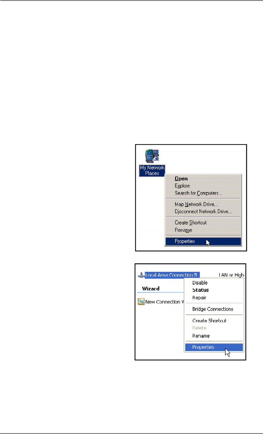
1. Right-click the My Network
Places icon in the Windows®
desktop, then select Properties
from the pop-up menu. The
Network and Dial-up
Connections window appears.
2. Right-click the network adapter
used by the the SmartAnt
SAA04-05224A, then select
Properties from the pop-up
menu. The Local Area
Connection Properties
window appears.
3. Configuration
20 SmartAnt
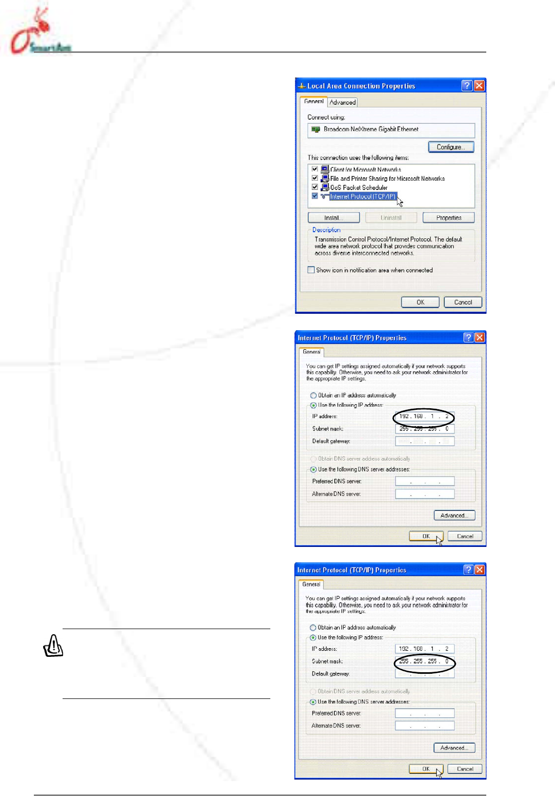
3. Double-click the Internet
Protocol (TCP/IP) item to
display the Internet Protocol
(TCP/IP) Properties window.
4. Check the Use the following
IP address option, then enter
the IP address for the network
adapter. The IP address must
be 192.168.1.X.(Xcan be any
number between 2 and 254 that
is not used by another device.)
5. Set the Subnet Mask to 255.
255.255.0. Click OK when
finished.
Changing the TCP/IP settings
may require system restart.
Switch on the SAA04-05224A
immediately after rebooting.
3. Configuration