Smartware USN3D201 Smartcard Reader User Manual USN3e MX3e 3I3P
Smartware Smartcard Reader USN3e MX3e 3I3P
Contents
User Manual.pdf

USN3e, MX3e-3I3P - Datasheet V2R01a
ULTRASMART™ TRIPLE DUAL INTERFACE FOR PRODUCTION
(USN3e, MX3e-3I3P)
Industrial Personalization Board for smartcard and chip card module.
Datasheet V2R01a
Date: December 2013

USN3e, MX3e-3I3P - Datasheet V2R01a
2 CONFIDENTIAL © 2013, Smartware
Copyright
All rights of translation adaptation and reproduction by any mean reserved for all the countries.
Any reproduction or any complete or partial representation of the pages published in this work, made
without the written permission of SMARTWARE is illicit and constitutes an imitation, whatever mean is
used. Only reproductions strictly reserved for the private use of the purchaser and not intended to be
used collectively are authorized. So are the short quotations justified by the scientific or informative
nature of the work which they are extracted from (art L.122-4 L. 122-5 and L. 335-2 of the French
Code ruling on intellectual property).
© SMARTWARE, Les ULIS, France, 1999-2013
Disclaimers
Information in this document is subject to change without notice and does not represent a
commitment on the part of SMARTWARE.

USN3e, MX3e-3I3P - Datasheet V2R01a
© 2013, Smartware CONFIDENTIAL 3
Contents
1Overview ............................................................................................................ 5
2Block diagram .................................................................................................... 6
3Functional description ...................................................................................... 7
3.1Cores ......................................................................................................................................... 7
3.2Contact interfaces .................................................................................................................... 7
3.2.1Protocol & Standard ................................................................................................................... 7
3.2.1.1ISO/IEC 7816-3, ISO/IEC 7816-4 ............................................................................. 7
3.2.1.2SWP .......................................................................................................................... 7
3.2.2Basic measurement methods ..................................................................................................... 8
3.2.2.1Continuity test ........................................................................................................... 8
3.2.2.2Open / Short test ....................................................................................................... 8
3.3Contactless interfaces ............................................................................................................. 9
3.3.1Protocol & Standard ................................................................................................................... 9
4Technical characteristics ............................................................................... 10
4.1Mechanical layouts ................................................................................................................ 10
4.2Physical interfaces ................................................................................................................. 12
4.2.1.1SCX Pinout .............................................................................................................. 12
4.2.1.2CLX Pinout .............................................................................................................. 12
4.2.1.3J30 Pinout ............................................................................................................... 13
4.2.1.3.1USN3e model ....................................................................................................... 13
4.2.1.3.2MX3e-3I3P model ................................................................................................ 14
4.2.2Switches ................................................................................................................................... 15
4.2.2.1SWCFG ................................................................................................................... 15
4.2.2.2SWX ........................................................................................................................ 15
4.2.3LEDS ........................................................................................................................................ 16
4.3Electrical characteristics ....................................................................................................... 17
4.3.1Contact interfaces .................................................................................................................... 18
4.3.1.1Pin drivers ............................................................................................................... 18
4.3.1.2Measurement .......................................................................................................... 18
4.3.2Contactless interfaces .............................................................................................................. 19
5Contact information ........................................................................................ 20
6REGULATORY .................................................................................................. 21
7Revision history ............................................................................................... 25

USN3e, MX3e-3I3P - Datasheet V2R01a
4 CONFIDENTIAL © 2013, Smartware
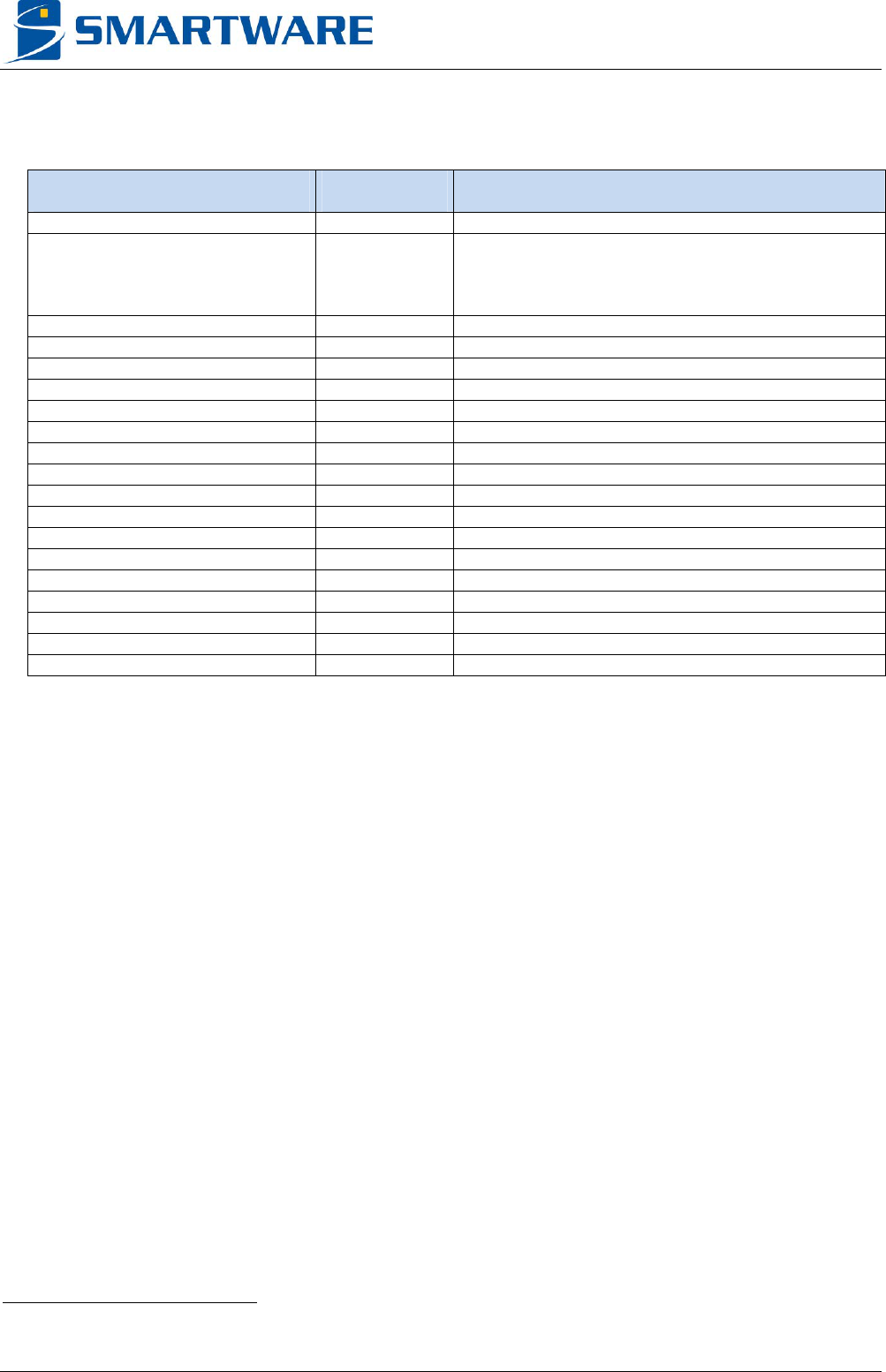
Abbreviations
ESD Electrostatic Discharge
ISO7816 ISO Standard for Contact Smartcard
SWP Single Wire Protocol
SPU Serial Protocol User
ETU Elementary Time Unit
AL Active Low
AH Active High
FI Clock Rate conversion factor
DI Baud Rate Adjustment factor
CD Character Duration
ODMT Opposite Direction Minimum Time
WWT Work Waiting Time
CWT Character Waiting Time
BWT Block Waiting Time
BGT Block Guard Time
APDU Application Protocol Data Unit
SHDLC Simplified High Level Data Link Control
CLT ContactLess Tunnelling Protocol
ACT Activation Protocol
CRC Cyclic redundancy check
ISO International Organization for Standardization
DAC Digital to Analog Converter
ADC Analog to Digital Converter
NAD Node Address
CID Card Identifier
FSCI Card Frame size Integer
FSDI Reader Frame size Integer
SOF Start of frame
EOF End of frame
Glossary
Modulation index: Defined as the voltage ratio (Vmax - Vmin) / (Vmax + Vmin).
USN3e, MX3e-3I3P - Datasheet V2R01a
© 2013, Smartware CONFIDENTIAL 5
1 OVERVIEW
The USN3e and MX3e-3I3P are complete solutions for the
personalization of contact/contactless card. The USN3e is perfect for
Smartware industrial rack integration while MX3e-3I3P have been
designed for the new Datacard MX smartcard module.
Features
CORE:
Hardware specification
- 32 bit Freescale Coldfire® CPUs running at 240 MHz
- 64 MB of RAM / 8 MB of Flash memories
Contact interfaces:
Supported contact protocols:
- ISO/IEC 7816-3 (T=0 / T=1)
- SWP (ETSI TS 102 613 and TS 102 622)
- Memory cards
- Proprietary protocols
Configurable hardware:
- Contacts voltage from 1.65 to 5.5 Volts.
- Communication frequency from 1 to 20 MHz (ISO 7816)
- User-specific protocol on all contacts
- C1 current limit: 200 mA
- C7 Boost functionality
Electrical tests:
- Open / short test
- Continuity test
Contactless interfaces:
Supported contactless protocols:
- ISO 14443 A / B up to 424 kbps
- PayPass A / B
- FeliCaTM
- MifareTM / Mifare+TM
Configurable hardware:
- RF output power
- Various communication protocol parameters
In system firmware updates.
Target Application
Production environment
Electrostatic discharge sensitivity
The USN3e and MX3-3I3P uses
semiconductors that can be damaged by
electrostatic discharge (ESD). Observe
precautions for handling. Damage due to
inappropriate handling is not covered by the
warranty.
Handling and connections should be done
without power supply.This product includes
a hot surface.
A fire enclosure must be provided in the
end product.
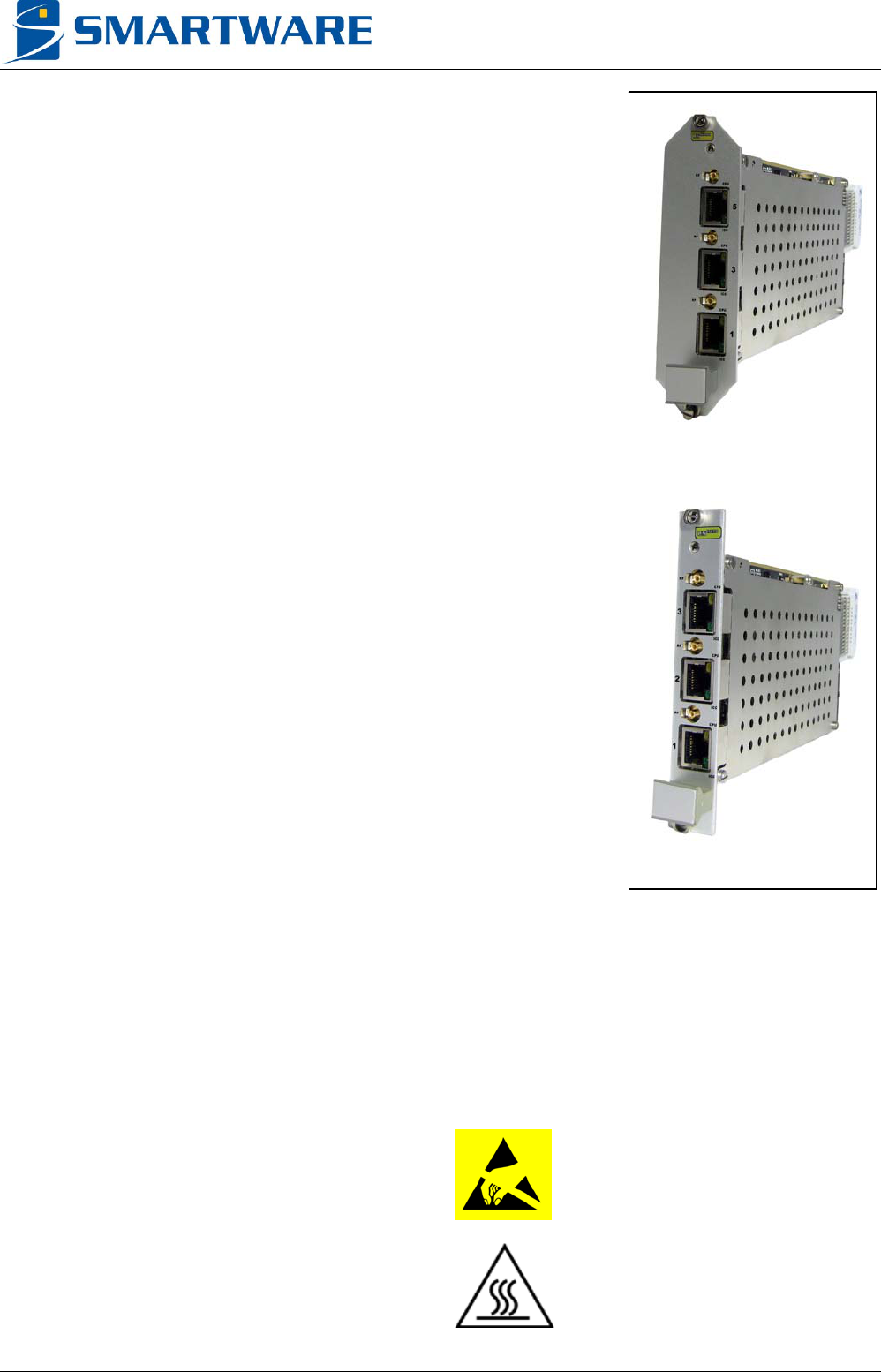
MX3e-3I3P
USN3e
USN3e, MX3e-3I3P - Datasheet V2R01a
6 CONFIDENTIAL © 2013, Smartware
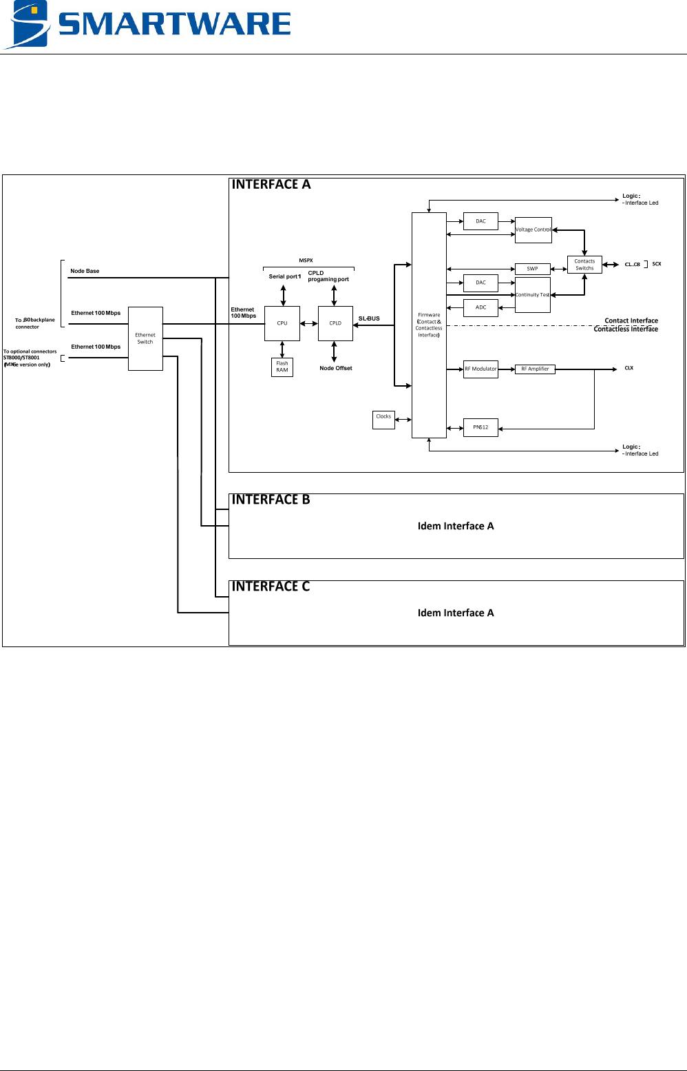
2 BLOCK DIAGRAM
Below is a simplified synoptic of USN3e and MX3e-3I3P.
Figure 1

USN3e, MX3e-3I3P - Datasheet V2R01a
© 2013, Smartware CONFIDENTIAL 7
3 FUNCTIONAL DESCRIPTION
The USN3e and MX3e-3I3P includes three CPU cores and three dual communication interfaces for
contact and contactless smartcards or smart objects.
The MLOS / CARD drivers manage the functionalities of the USN3e and MX3e-3I3P. Please refer to
their documentation for more information.
3.1 CORES
The USN3e and MX3e-3I3P includes three US-Nano boards which integrates a 32 bit Freescale
ColdFire® CPU.
The Cores manage several communication interfaces such as Ethernet 10 / 100 Mbps, and serial
port.
The Cores are powered with MLOS proprietary embedded multitask system.
3.2 CONTACT INTERFACES
3.2.1 Protocol & Standard
3.2.1.1 ISO/IEC 7816-3, ISO/IEC 7816-4
Embedded software allows the easy configuration of:
FI / DI (ETU).
Timing parameters such as character duration, BGT, CWT, BWT, WWT, ODMT…
Frequency.
Automatic protocol handling.
Error management with parity error retry mechanism (Configurable number of retries)
APDU exchanges.
Contact lines for custom protocols.
3.2.1.2 SWP
Embedded software allows:
Activation, Deactivation.
Automatic CRC management (Compute & Check).
Bit stuffing management.
Manage payload exchanges according to SWP standard.
Allows interfacing ACT, SHLDC, or CLT Logical Link Layers.
USN3e, MX3e-3I3P - Datasheet V2R01a
8 CONFIDENTIAL © 2013, Smartware
3.2.2 Basic measurement methods
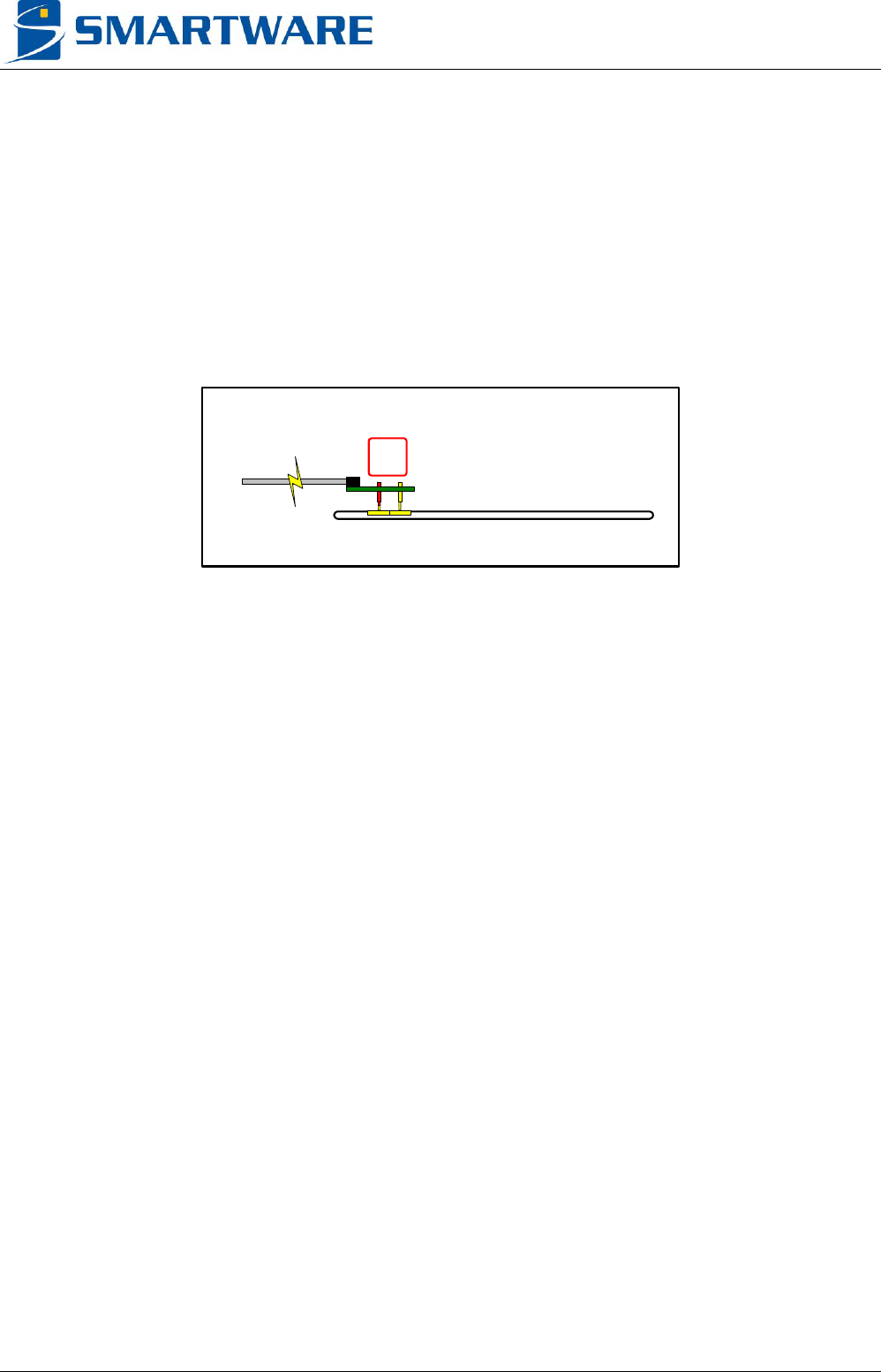
3.2.2.1 Continuity test
Embedded software provides the following functionalities for the contact interface:
Check the connection from the contact interface to the smartcard pads.
Measure the serial resistors (due to cable, test head, or deficient contact pin)
Check if the measurement is possible. For this test, C5 should not be linked to the ground/earth.
This test is done with all others contacts in high impedance state.
The method will use the smartcard clamp diodes to perform the measurement.
This test can help you to anticipate a change of the contact pins, or cables.
KO
Figure 2
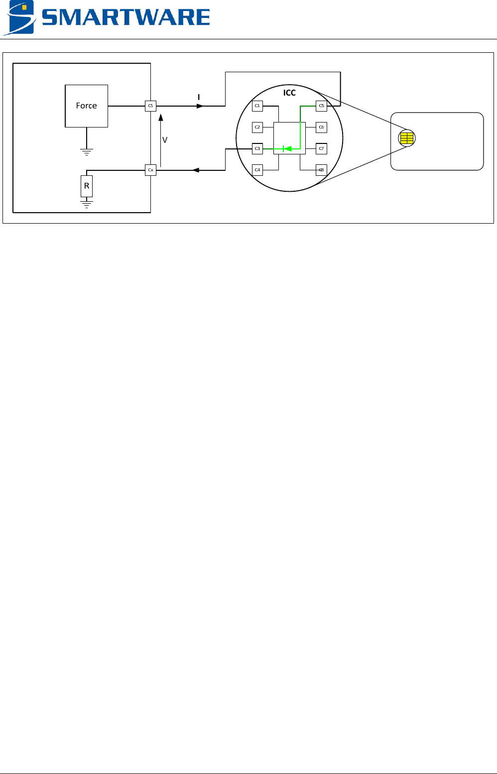
3.2.2.2 Open / Short test
Embedded software provides the following functionalities for the contact interface:
Check the smartcard clamp diodes between C1/2/3/4/6/7/8 and C5. The contact can be:
- Open (i.e.: no bonding, damaged diode)
- Short (i.e.: wrong bonding, shortcut, damaged diode…)
- OK (bonding and diodes OK)
Return the diode’s threshold voltage value.
Check if the measurement is possible. For this test, C5 should not be linked to the ground/earth.
This test is done with all others contacts in high impedance state.
A voltage is forced on contact C5, and a current will go through the smartcard diode.
The contact interface will then measure the diode threshold voltage, and determine the contact’s
status.
This measurement is datasheet specified only if the smartcard chip is connected to the contact
interface (without serial resistance).
If a serial resistor (lower than 2.2 kOhms) is present (i.e.: RC filter on contact C2), an embedded
compensation algorithm will allow threshold voltage measurement with degraded accuracy.
The maximal allowed capacitance is 100 nF between the contacts C1 and C5.
USN3e, MX3e-3I3P - Datasheet V2R01a
© 2013, Smartware CONFIDENTIAL 9
Figure 3
3.3 CONTACTLESS INTERFACES
3.3.1 Protocol & Standard
Embedded software provides the following functionalities for the contactless interface:
Adjustable field strength
Several timings parameters management such as Frame Waiting Time, Frame Delay Time,
Startup Guard Time, RFOnWait, Extra Guard Time…
Several protocol parameters management such as NAD, CID, FSCI, FSDI, SOF, EOF…
Automatic protocol handling.
Configurable retry mechanism
Raw mode allowing user custom protocols.
The USN3e and MX3e-3I3P can be used to communicate with cards in contactless mode using an
external antenna. It can also be used in direct contact mode by connecting chip card module or die
(wafer) pins to the RF output.
USN3e, MX3e-3I3P - Datasheet V2R01a
10 CONFIDENTIAL © 2013, Smartware
4 TECHNICAL CHARACTERISTICS
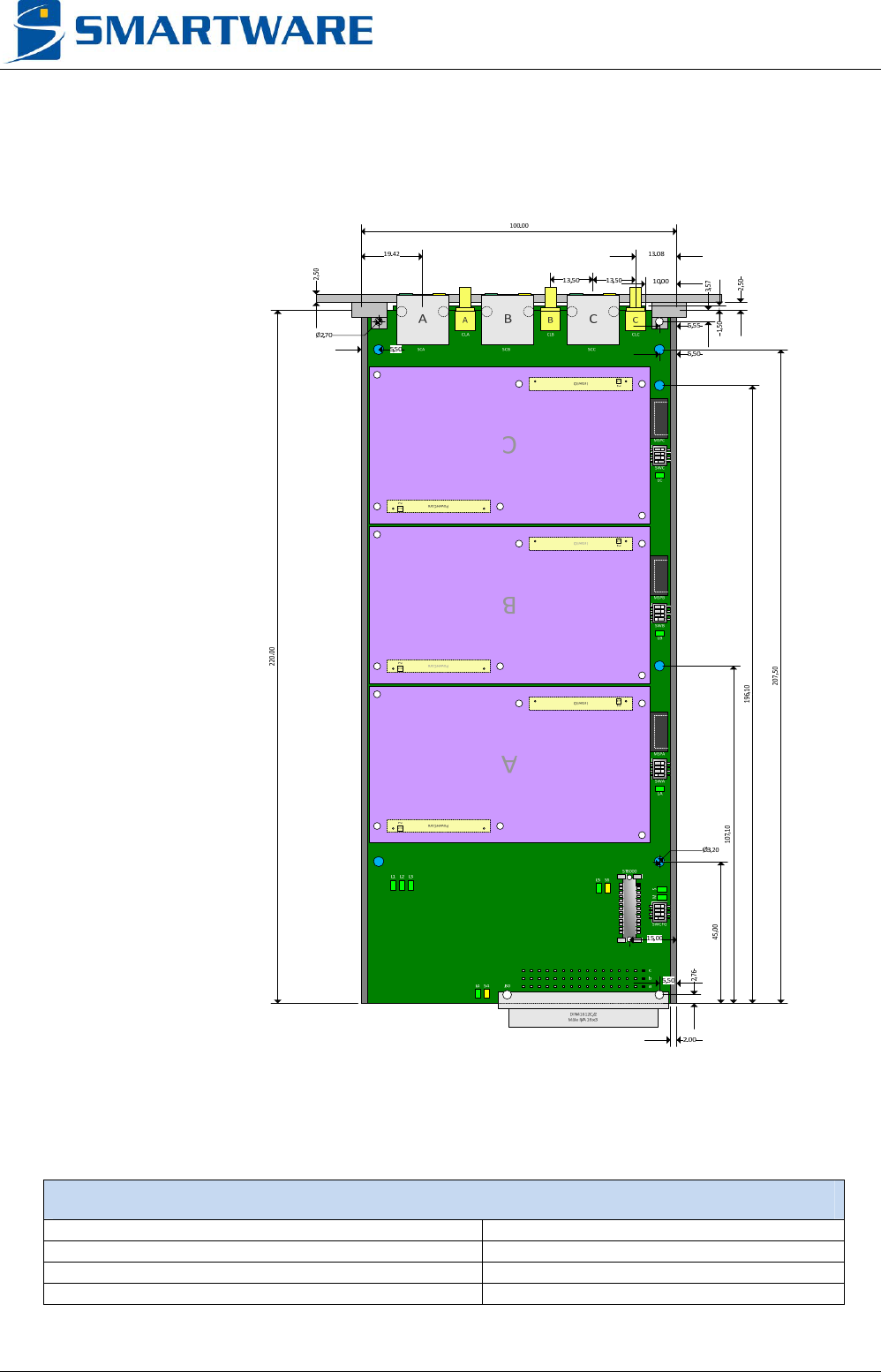
4.1 MECHANICAL LAYOUTS
Figure 4
The fixing attachment holes and side strips are connected to the USN3e and MX3e-3I3P ground.
GENERAL
Height 100 mm
Length 221.5 mm
Width 1.6 mm
Weight 360 g
USN3e, MX3e-3I3P - Datasheet V2R01a
© 2013, Smartware CONFIDENTIAL 11
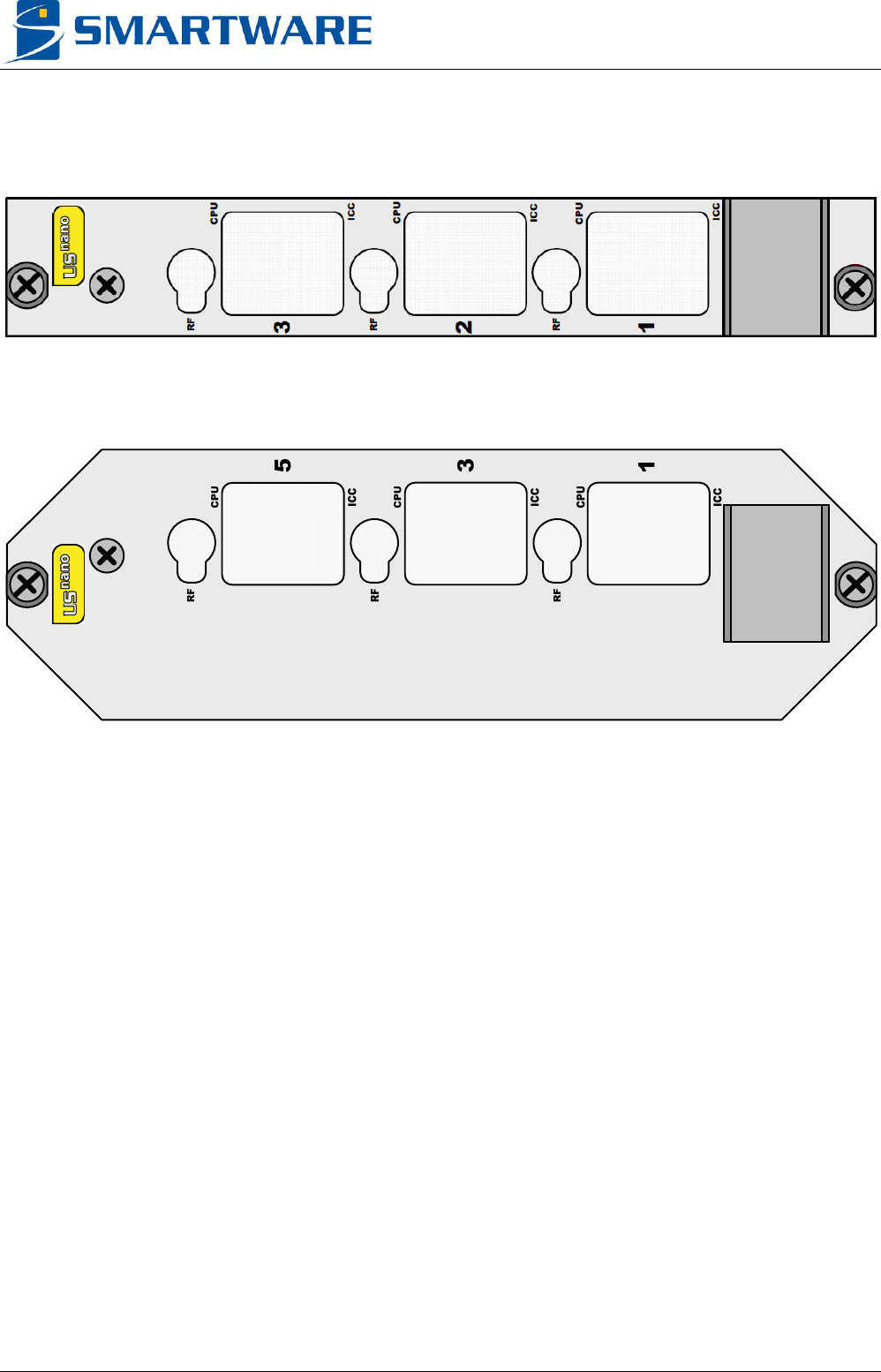
Below are the front panels delivered with USN3e and MX3e-3I3P.
Figure 5 : 3U / 4TE front panel (USN3e)
Figure 6 : 3U / 8TE front panel (MX3e-3I3P)
USN3e, MX3e-3I3P - Datasheet V2R01a
12 CONFIDENTIAL © 2013, Smartware
4.2 PHYSICAL INTERFACES
This chapter describes the physical interface.
As the three interfaces are similar, “X” refers to the interface identifier (A, B, or C)
4.2.1.1 SCX Pinout
This RJ45 connector is used for the contact interface.
It regroups several software selectable functionalities.
Pin Name 7816-3 SWP
1 CC3 CLK
2 CC5 GND GND
3 CC4 RFU1
4 CC8 RFU2
5 CC1 VCC VCC
6 CC6 SPU SWP I/O
7 CC2 RST
8 CC7 I/O
shield GND
4.2.1.2 CLX Pinout
This SMB connector provides the contactless interface.
Pin Name Description
Center RF_ANT RF output
Body Gnd Ground
USN3e, MX3e-3I3P - Datasheet V2R01a
© 2013, Smartware CONFIDENTIAL 13
4.2.1.3 J30 Pinout
This DIN41612 connector provides power, node identifier, serial ports, Ethernet port, safe mode, and
leds. The pinout configuration will depend of model.
4.2.1.3.1 USN3e model
Pin Name Description
A1, A4, B15, C15, B16, C16 Gnd Ground
A2, B2, C2, A3, B3, C3, A7, B7,
A8, B8, C8, A9, A10, B10, C10,
C11, A14, B14, C14
NC Not connected
A15, A16 +Vaa Main Power Supply (+12V)
B1 L1Tx Line 1 RS232 transmit (US-Nano A)
C1 L1Rx Line 1 RS232 receive (US-Nano A)
B4 Node0 Node Base bit 0
C4 Node1 Node Base bit 1
A5 Node2 Node Base bit 2
B5 Node3 Node Base bit 3
C5 Node4 Node Base bit 4
A6 Node5 Node Base bit 5
B6 Node6 Node Base bit 6
C6 Node7 Node Base bit 7
C7 Safe_Mode Active low Safe Mode
1
B9 +3V3 Internal +3.3V output
C9 LiLed Active Low Link Led
2
A11 ETH_BP_3P Ethernet Pair 3 +
3
B11 ETH_BP_3M Ethernet Pair 3 -
3
A12 ETH_BP_1P Ethernet Pair 1 +
B12 ETH_BP_2P Ethernet Pair 2 +
3
C12 ETH_BP_0P Ethernet Pair 0 +
A13 ETH_BP_1M Ethernet Pair 1 -
B13 ETH_BP_2M Ethernet Pair 2 -
3
C13 ETH_BP_0M Ethernet Pair 0 -
1 Internal pull up resistor
2 Internal serial resistor for current limiting function
3 Termination only
USN3e, MX3e-3I3P - Datasheet V2R01a
14 CONFIDENTIAL © 2013, Smartware
4.2.1.3.2 MX3e-3I3P model
Pin Name Description
A1, B1, C1 Gnd Ground
A2, B2, C2, C4, C5, C6, C7, C8,
A9, B9, C9, A10, B10, C10, A11,
B11, C11, C12, A13, C13, A14,
C14, A15, C15, A16, C16
NC Not connected
A3, B3, C3 +Vaa Main Power Supply (+12V)
A4 Node2 Node Base bit 2
B4 Node3 Node Base bit 3
A5 Node0 Node Base bit 0
B5 Node1 Node Base bit 1
A6 ETH_BP_1P Ethernet Pair 1 +
B6 ETH_BP_1M Ethernet Pair 1 -
A7 ETH_BP_0P Ethernet Pair 0 +
B7 ETH_BP_0M Ethernet Pair 0 -
A8 Node4 Node Base bit 4
B8 Node5 Node Base bit 5
A12 Node6 Node Base bit 6
B12 Node7 Node Base bit 7
B13 ETH_BP_2P Ethernet Pair 2 +
4
B14 ETH_BP_2M Ethernet Pair 2 -
4
B15 ETH_BP_3P Ethernet Pair 3 +
4
B16 ETH_BP_3M Ethernet Pair 3 -
4
4 Termination only
USN3e, MX3e-3I3P - Datasheet V2R01a
© 2013, Smartware CONFIDENTIAL 15
4.2.2 Switches
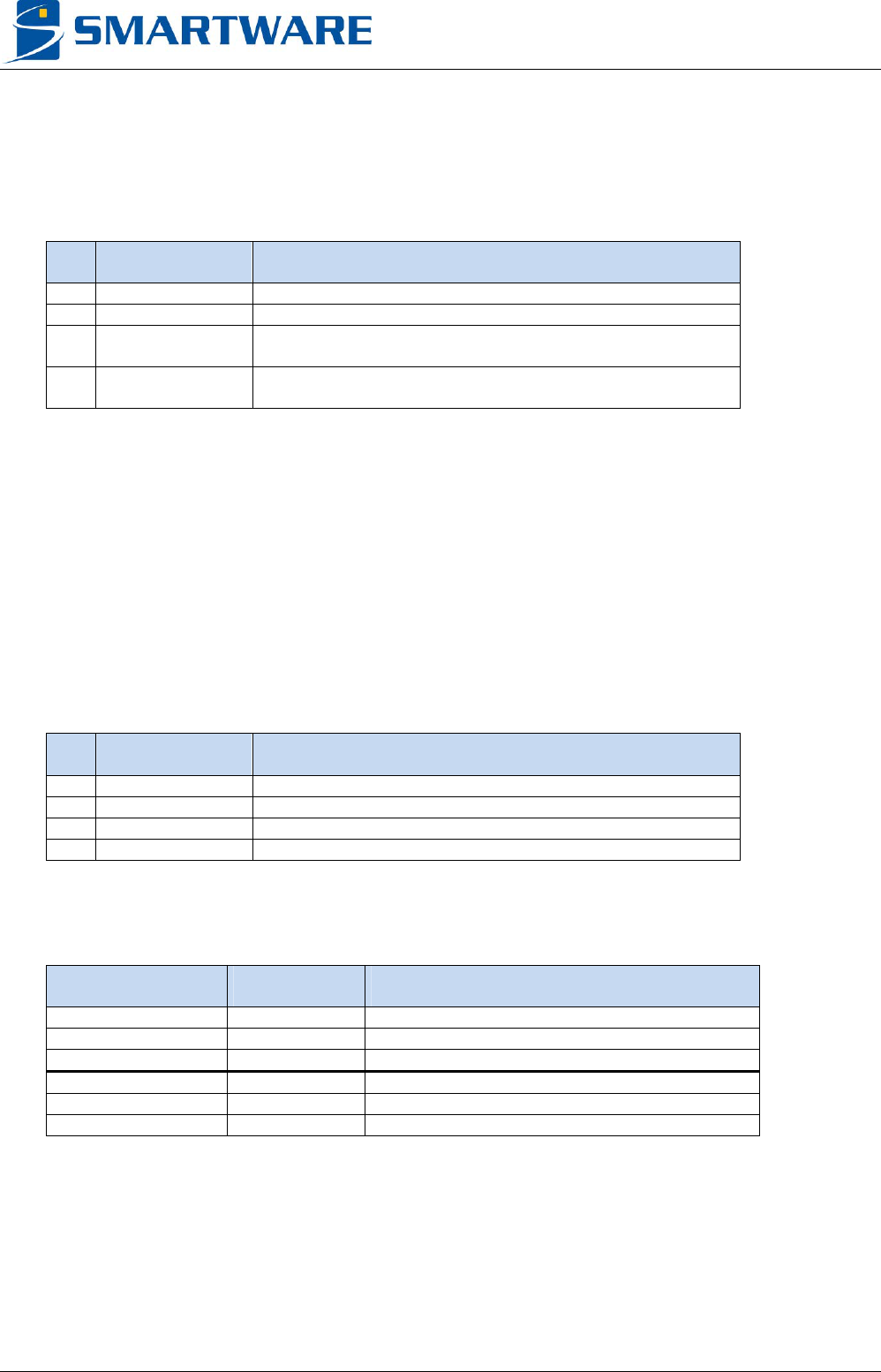
4.2.2.1 SWCFG
This micro switch defines specific configuration mode.
Pin Name Description
1 Node 7 Node Base (bit 7)
2 Node 6 Node Base (bit 6)
3 Mono Mode ON : Boot in mono mode
OFF : Normal operation
4 Safe Mode ON : Boot in safe mode
OFF : Normal operation
The Safe Mode will not start the packages, and use a default MLOS.ini as boot parameters.
The Mono Mode will not start the MLOS system. Only serial port will be available to reload a correct
MLOS system.
4.2.2.2 SWX
These micro switches define the associated US-Nano board node by adding this value to the global
Node base (defined on J30 and/or SWCFG) common to all US-Nano.
US-Nano Node (Interface X) = Node base + Node Offset (Interface X)
Pin Name Description
1 Node offset (0) Node offset bit 0
2 Node offset (1) Node offset bit 1
3 Node offset (2) Node offset bit 2
4 RFU
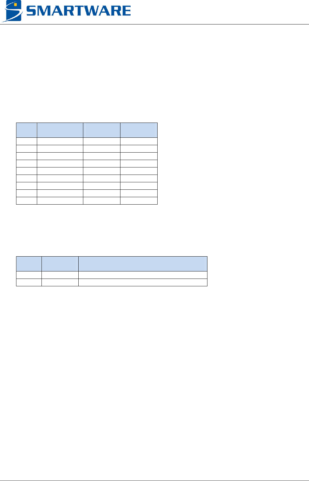
The default configurations of the Node Offset are:
Model Interface Node offset value
USN3e A 0
USN3e B 1
USN3e C 2
MX3e-3I3P A 0
MX3e-3I3P B 2
MX3e-3I3P C 4
USN3e, MX3e-3I3P - Datasheet V2R01a
16 CONFIDENTIAL © 2013, Smartware
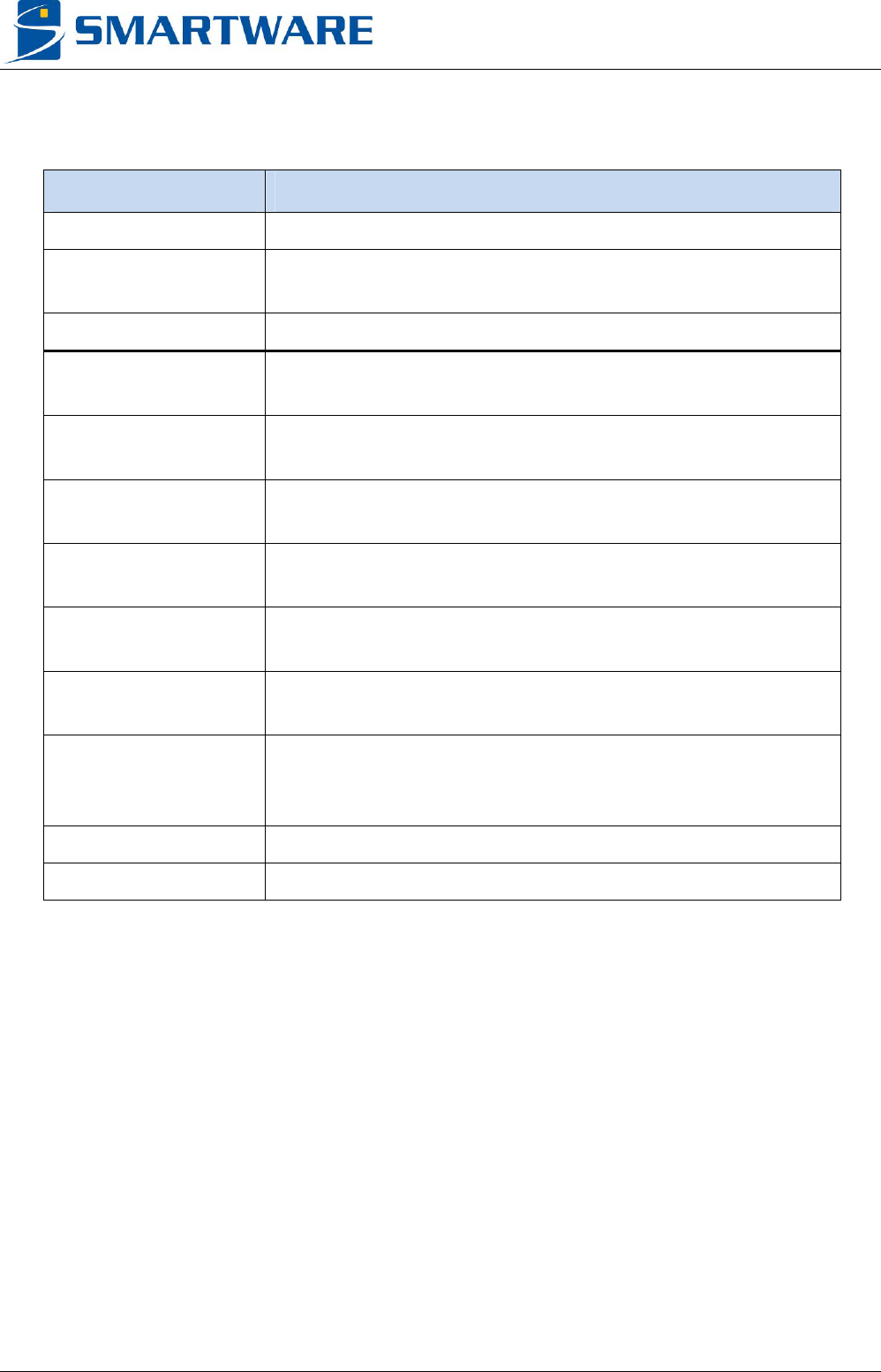
4.2.3 LEDS
Name Description
SCX_Green Contact interface power on status LED
SCX_Yellow CPU status LED
Blink if CPU is running correctly
CLX_Green Contactless interface power on status LED
S Safe Mode Status
ON if Safe Mode is activated
M Mono Mode Status
ON if Mono Mode is activated
L1, LA US-Nano Ethernet link status (Interface A)
ON if link is established
L2, LB US-Nano Ethernet link status (Interface B)
ON if link is established
L3, LC US-Nano Ethernet link status (Interface C)
ON if link is established
L4 Backplane Ethernet link status
ON if link is established
S4
Backplane Ethernet Speed
ON (100 MBps)
OFF (10 MBps)
L5 Not used for models USN3e and MX3e-3I3P
S5 Not used for models USN3e and MX3e-3I3P

USN3e, MX3e-3I3P - Datasheet V2R01a
© 2013, Smartware CONFIDENTIAL 17
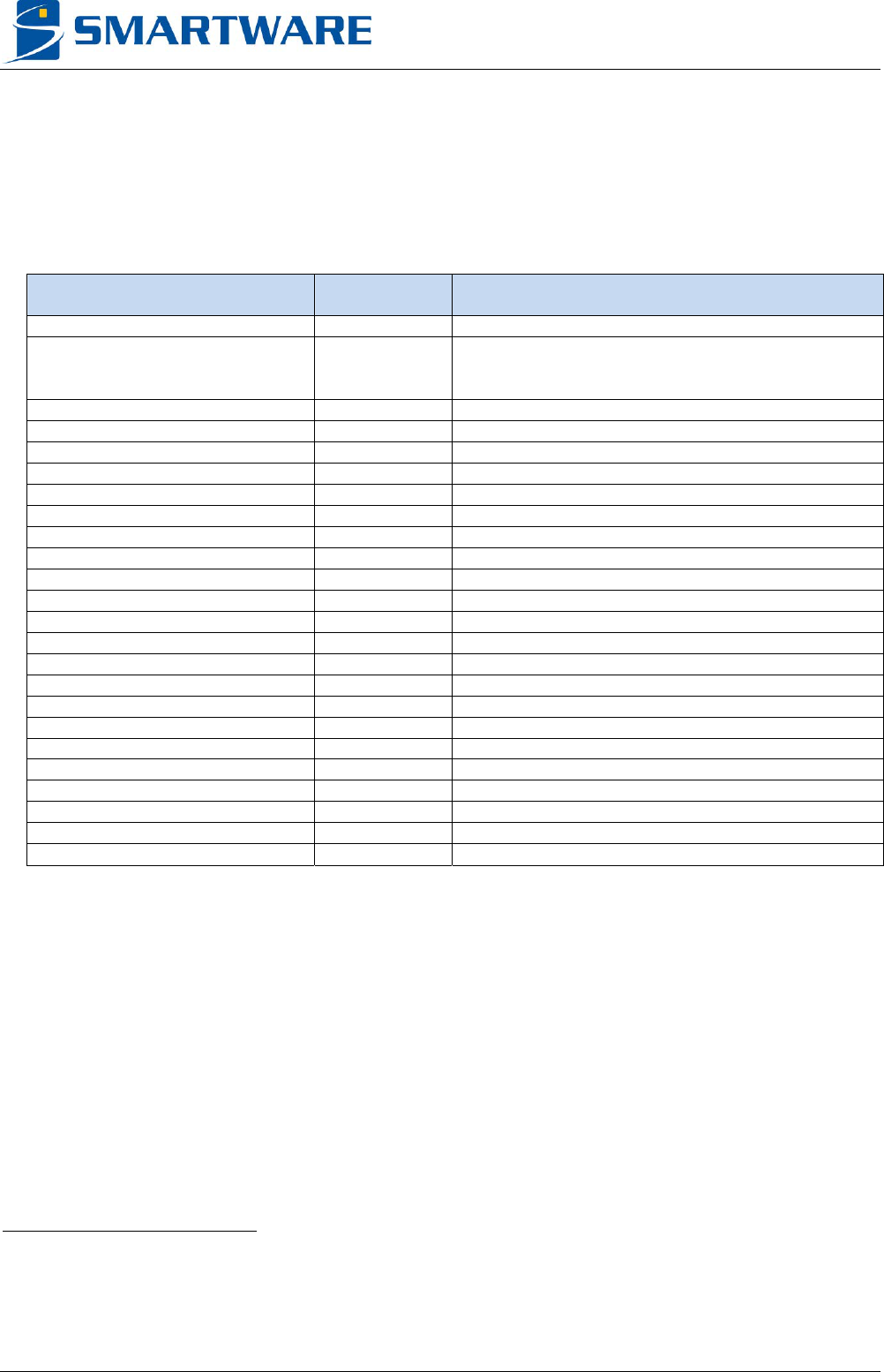
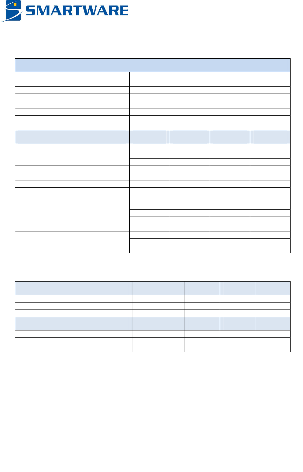
4.3 ELECTRICAL CHARACTERISTICS
GENERAL
Operating environment 0 °C to 40 °C
POWER SUPPLY Conditions Typical Precision
Voltage 12 V ±1.2V
Current (Vaa = 12 V) Idle 950 mA
Max Current (Vaa = 12 V)
RF Output short
circuited
1850 mA
USN3e, MX3e-3I3P - Datasheet V2R01a
18 CONFIDENTIAL © 2013, Smartware
4.3.1 Contact interfaces
4.3.1.1 Pin drivers
CONTACT DRIVING CAPABILITY
C1 (VCC) Vcc, HiZ
C2 (RST) VOH, VOL, HiZ
5
C3 (CLK) VOH, VOL, Clock, HiZ
5
C4 (RFU1) VOH, VOL, HiZ
5
C5 (GND) Gnd, HiZ
5
C6 (SPU) VOH, VOL, SWIO, HiZ
5
C7 (I/O) VOH, VOL, Pull-up
6
, HiZ
C8 (RFU2) VOH, VOL, HiZ
5
CONTACT SIGNAL CAPABILITY Min Max Resolution Precision
Vcc 1.65 V 5.50 V 10 mV ±20 mV
Icc limitation
ISO/SWP Mode 200 mA
VOH V
cc - 0.1 V Vcc
VOL 0 V 0.1 V
VIH 0.8 x Vcc
VIL 0.55 V
Current limitation
1.65 < Vcc < 1.95 ±4 mA
2.30 < Vcc < 2.70 ±8 mA
3.00 < Vcc < 3.60 ±24 mA
4.50 < Vcc < 5.50 ±32 mA
Clock
ISO Mode 1 MHz 20 MHz
C5 impedance to ground 50 m
4.3.1.2 Measurement
CONTINUITY TEST Conditions Min Typical Max
Resistor measurement range 0 10 k
Resistor measurement precision R < 1 k ±100
R > 1 k ±10 %
OPEN/SHORT TEST Conditions Min Typical Max
Current to perform measurement 2,5 mA 3,2 mA
Diode threshold voltage range 0.1 V 2.5 V
Diode threshold voltage precision 0.1 V
5 470 k internal pull-down
6 10 k and 4.7 k software selectable internal pull-ups connected to Vcc
USN3e, MX3e-3I3P - Datasheet V2R01a
© 2013, Smartware CONFIDENTIAL 19
4.3.2 Contactless interfaces
CONTACTLESS DRIVING CAPABILITY
RF output Modulated RF Signal
CONTACTLESS SIGNAL CAPABILITY Min Max Typical Precision
RF Offset 400 mV
RF Signal peak to peak (R = ) 2 Vpp 20 Vpp ± 2% ± 0.05 Vpp
RF Signal power (R = 50 ) 250 mW
(+24 dBm)
RF Output Impedance 50 ± 5
Current limitation
Short circuit current (R = 0 ) RMS 150 mA
Recommended full power
short circuit max duration
60 s
RF Frequency 13.56 MHz ± 7 kHz
Modulation Index
ISO14443 A / PayPass A / Mifare 90 % 100 % 100 %
ISO14443 B / PayPass B 9.5 % 12.5 % 11 %
FeliCa
TM
9.5 % 12.5 % 11 %

USN3e, MX3e-3I3P - Datasheet V2R01a
20 CONFIDENTIAL © 2013, Smartware
5 CONTACT INFORMATION
For more information, please send an email to: support@smartware.fr
For ordering information, please send an email to: sales@smartware.fr

USN3e, MX3e-3I3P - Datasheet V2R01a
© 2013, Smartware CONFIDENTIAL 21
6 REGULATORY
The models USN3e and MX3e-3I3P are CE, FCC / IC modular approval, and RoHS compliant.
Les modèles USN3e, et MX3e-3I3P sont certifiés CE, FCC / IC approbation modulaire, et RoHS.
WARNING TO USERS
Warning 1: The USN3e and MX3e-3I3P models are considered as components that will be operated in combination with the final
equipment. Then, the final equipment (including power supply system) still needs to re-confirm that the whole system complies with the local
EMC directives.
Les modèles USN3e et MX3e-3I3P sont considérés comme des composants qui seront intégrés dans un équipement hôte. Le fabricant de
l’équipement hôte (système d’alimentation inclus) devra alors reconfirmer que le système complet répond toujours aux différentes normes
locales.
Warning 2: The USN3e and MX3e-3I3P models are low power radiofrequency emitters, and then specific precaution should be taken to
restrict the human presence near the antennas.
We recommend that persons should be at least at 20 cm far from the emitting antennas. This information also has to be mentioned in the
end product.
Access should only be authorized to qualified personal.
If the product is not installed and used in accordance with the instruction manual, it may cause harmful interference to radio
communications.
Les modèles USN3e et MX3e-3I3P intègrent plusieurs émetteurs radiofréquence. Des précautions particulières doivent être prises pour
contrôler la présence humaine près des antennes.
Nous recommandons qu’aucune personne ne puisse se situer à une distance inférieure à 20 cm des antennes. Cette information doit
également être mentionnée sur l’équipement hôte.
L’accès doit être restreint au personnel qualifié.
Si le produit n’est pas installé et utilisé tel que décrit dans la notice, il peut engendrer des perturbations radioélectriques.
Warning 3: To reduce the risk of fire or injury to persons, follow these instructions:
All maintenance and servicing of this device must be performed in a safe area away from hazardous locations. Disconnect all power before
servicing.
Use an earthed bracelet to avoid ESD damages.
Power supply must be SELV, no energy hazard.
Afin de réduire les risques de feu ou blessure aux personnes, suivez les instructions suivantes :
Toutes les opérations de service et de maintenance doivent être réalisées dans un endroit sécurisé. Déconnectez toutes les alimentations
avant manipulation.
Utilisez un bracelet relié à la terre pour éviter des dommages liés aux ESD.
L’alimentation doit être SELV, aucun danger énergétique.
Warning 4: To comply with directives, the backplane Ethernet cable length should be less than 3 meters.
Pour être en conformité avec les normes, le câble du connecteur Ethernet du fond de panier doit avoir une longueur inférieure à 3m.

USN3e, MX3e-3I3P - Datasheet V2R01a
22 CONFIDENTIAL © 2013, Smartware
Warning 5: This device has been designed to operate with the antenna(s) listed below. Antennas not included in this list are strictly
prohibited for use with this device
List of acceptable antenna(s):
- T70x45x2
Ce dispositif a été conçu pour fonctionner avec les antennes énumérées ci-dessous. Les antennes non incluses dans cette liste sont
strictement interdites pour l’exploitation de ce dispositif.
Liste des antennes acceptables :
- T70x45x2
Warning 6: Use of shielded contact cable (with ferrite ref RICHOH RKCF-06-A5) is mandatory to comply with standards.
L’utilisation d’un câble d’interface contact blindé (accompagné d’une ferrite RICHOH RKCF-06-A5) est nécessaire pour se conformer aux
limites réglementaires.
Warning 7: To comply with directives, RF power may be set from power 0 to power 10.
Pour être en conformité avec les normes, la consigne de puissance RF peut être réglée de puissance 0 à puissance 10.
Warning 8: In case of collocated transmitters, the maximum number of transmitters in a small place should be 48.
Dans le cas de plusieurs émetteurs, le nombre maximum d’émetteurs dans un petit espace est de 48.
Warning 9: The product shall not be modified without written authorisation of Smartware. Changes or modifications not expressly approved
by the party responsible for compliance could void the user's authority to operate the equipment.
Le produit ne doit pas être modifié sans l’autorisation écrite de Smartware. Changements et modifications non approuvés par l’organisme
responsable de la conformité pourrait annuler l’autorité de l’utilisateur à opérer cet équipement.
Warning 10: The end product’s sticker should mention that it “contains a FCCID: RPM-USN3D201 and IC: 4783A- USN3D201” product.
L’étiquette du produit hôte doit mentionner « Contient un FCCID: RPM- USN3D201 et IC: 4783A- USN3D201».

USN3e, MX3e-3I3P - Datasheet V2R01a
© 2013, Smartware CONFIDENTIAL 23
Warning 11:
WARNING TO USERS IN THE UNITED STATES
Federal Communication Commission Interference
Section 15.105 Information to the user
(a) For a Class A digital device or peripheral, the instructions furnished the user shall include the following or similar statement, placed in a
prominent location in the text of the manual:
Note: This equipment has been tested and found to comply with the limits for a Class A digital device, pursuant to part 15 of the FCC Rules.
These limits are designed to provide reasonable protection against harmful interference when the equipment is operated in a commercial
environment. This equipment generates, uses, and can radiate radio frequency energy and, if not installed and used in accordance with the
instruction manual, may cause harmful interference to radio communications. Operation of this equipment in a residential area is likely to
cause harmful interference in which case the user will be required to correct the interference at his own expense.
This device (USN3e and MX3e-3I3P models) complies with Part 15 of the FCC Rules. Operation is subject to the following two conditions:
(1) This device may not cause harmful interference, and (2) this device must accept any interference received, including interference that
may cause undesired operation.
NO UNAUTHORIZED MODIFICATIONS
47 CFR Section 15.21
CAUTION: This equipment may not be modified, altered, or changed in any way without signed written permission from Smartware.
Unauthorized modification may void the equipment authorization from the FCC and will void the Smartware warranty.
This device complies with FCC RF radiation exposure limits set forth for general population (uncontrolled exposure). This device must be
installed to provide a separation distance of at least 20cm from all persons and must not be collocated or operating in conjunction with any
other antenna or transmitter other than authorized in the present document.
.

USN3e, MX3e-3I3P - Datasheet V2R01a
24 CONFIDENTIAL © 2013, Smartware
Warning 12:
WARNING TO USERS IN THE CANADA / ATTENTION POUR LES UTILISATEURS AU CANADA
This device complies with Industry Canada licence-exempt RSS standard(s). Operation is subject to the following two conditions: (1) this
device may not cause interference, and (2) this device must accept any interference, including interference that may cause undesired
operation of the device.
Under Industry Canada regulations, this radio transmitter may only operate using an antenna of a type and maximum (or lesser) gain
approved for the transmitter by Industry Canada.
To reduce potential radio interference to other users, the antenna type and its gain should be so chosen that the equivalent isotropically
radiated power (e.i.r.p.) is not more than that necessary for successful communication.
This device complies with Industry Canada RF radiation exposure limits set forth for general population (uncontrolled exposure). This device
must be installed to provide a separation distance of at least 20cm from all persons and must not be collocated or operating in conjunction
with any other antenna or transmitter other than authorized in the present document.
Le présent appareil est conforme aux CNR d’Industrie Canada applicables aux appareils radio exempts de licence. L’exploitation est
autorisée aux deux conditions suivantes: (1) il ne doit pas produire de brouillage, et (2) l’utilisateur du dispositif doit être prêt a accepter tout
brouillage radioélectrique reçu, même si ce brouillage est susceptible de compromettre le fonctionnement du dispositif.
Conformément à la réglementation d’Industrie Canada, le présent émetteur radio peut fonctionner avec une antenne d’un type et d’un gain
maximal (ou inférieur) approuvé pour l’émetteur par Industrie Canada.
Dans le but de réduire les risques de brouillage radioélectrique à l’ intention d’autres utilisateurs, il faut choisir le type d’antenne et son gain
de sorte que la puissance isotrope rayonnée équivalente (p.i.r.e.) ne dépasse pas l’intensité nécessaire à l’établissement d’une
communication satisfaisante.
Le présent appareil est conforme aux niveaux limites d’exigences d’exposition RF aux personnes définies par Industrie Canada. Cet
appareil doit être installé afin d’offrir une distance de séparation d’au moins 20cm avec l’utilisateur, et ne doit pas être installé à proximité ou
être utilisé en conjonction avec une autre antenne ou un autre émetteur autre qu’autorisé dans le présent document.
This device has been designed to operate with the antenna(s) listed below. Antennas not included in this list are strictly prohibited for use
with this device
List of acceptable antenna(s):
- T70x45x2
Ce dispositif a été conçu pour fonctionner avec les antennes énumérées ci-dessous. Les antennes non incluses dans cette liste sont
strictement interdites pour l’exploitation de ce dispositif.
Liste des antennes acceptables :
- T70x45x2
This Class A digital apparatus complies with Canadian ICES-003.
Cet appareil numérique de la classe A est conforme à la norme NMB-003 du Canada.

USN3e, MX3e-3I3P - Datasheet V2R01a
© 2013, Smartware CONFIDENTIAL 25
7 REVISION HISTORY
VERSION DATE AUTHOR CHANGES
V2R01a December 2013 FA Original version