SofaWare Technologies SBX-11GWLAN-5 2.4G WLAN MINI PCI MODULAR User Manual WLG 1302 UserMan
SofaWare Technologies Ltd. 2.4G WLAN MINI PCI MODULAR WLG 1302 UserMan
UserManual.wiki
>
SofaWare Technologies
>
SBX 11GWLAN 5 User Manual
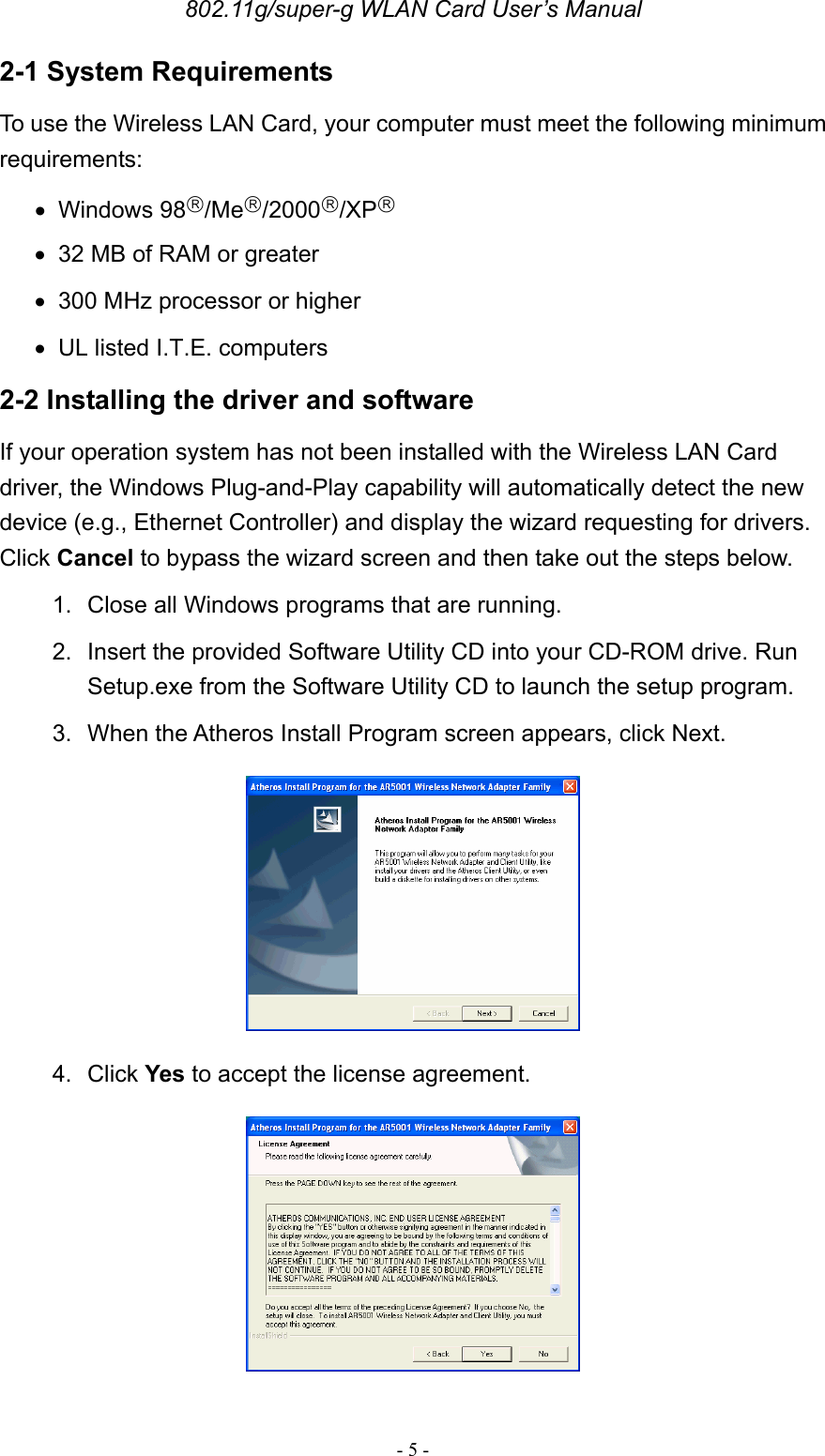
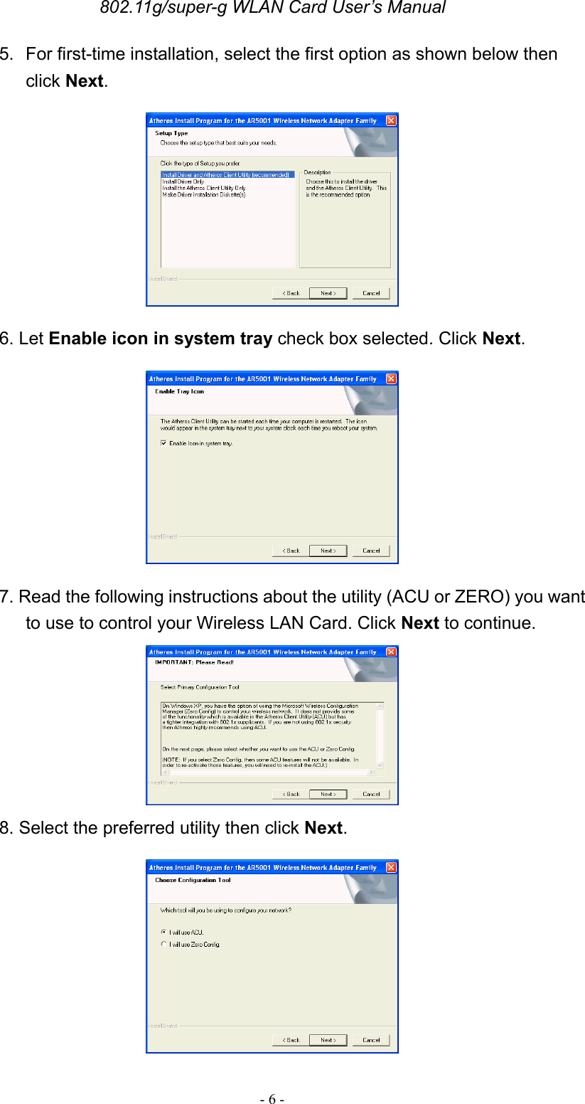
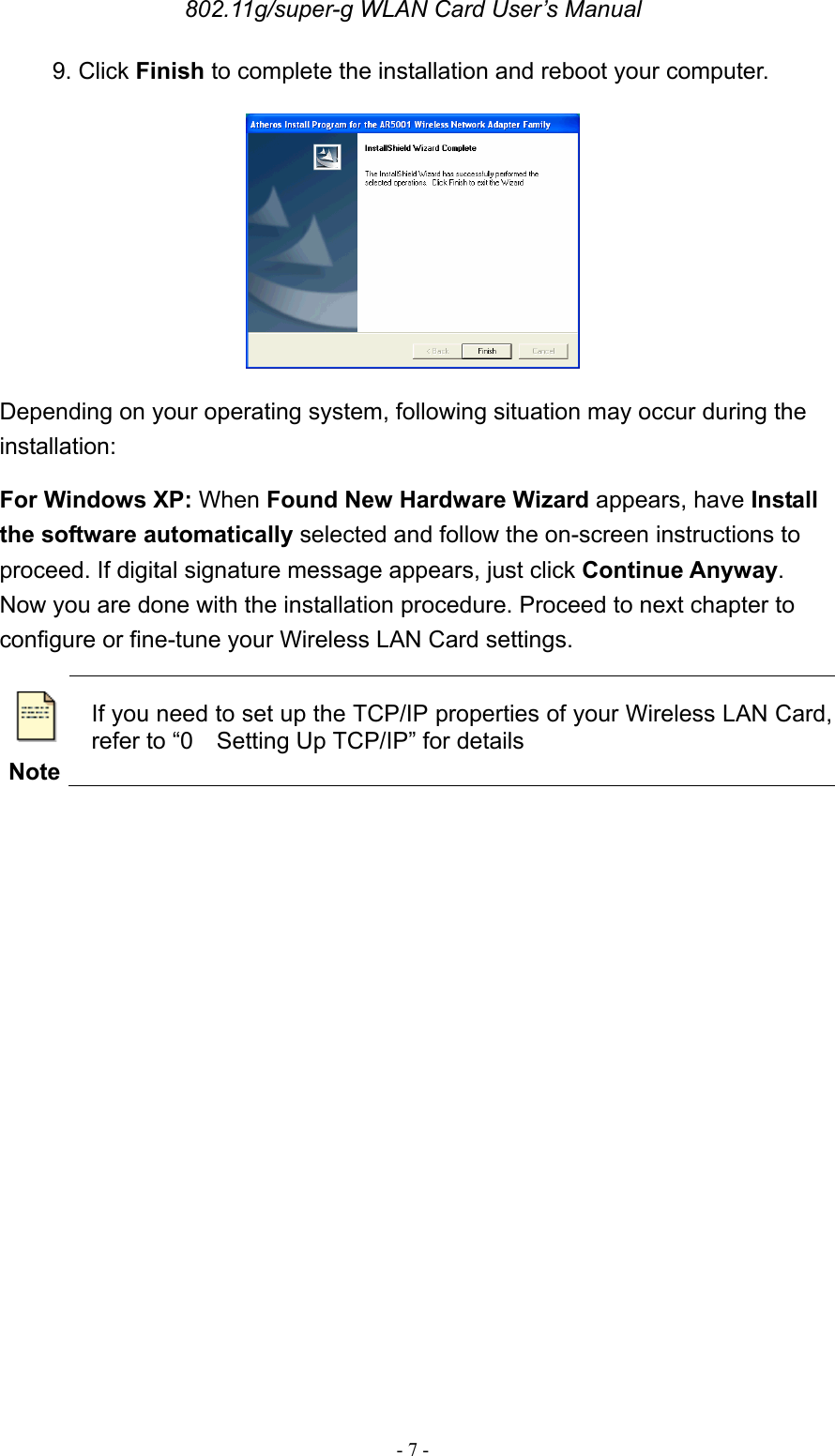
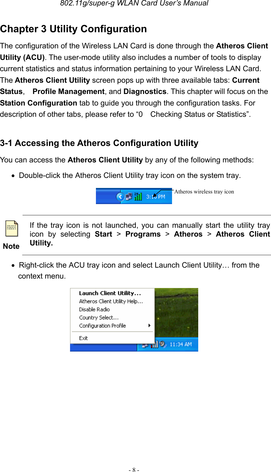
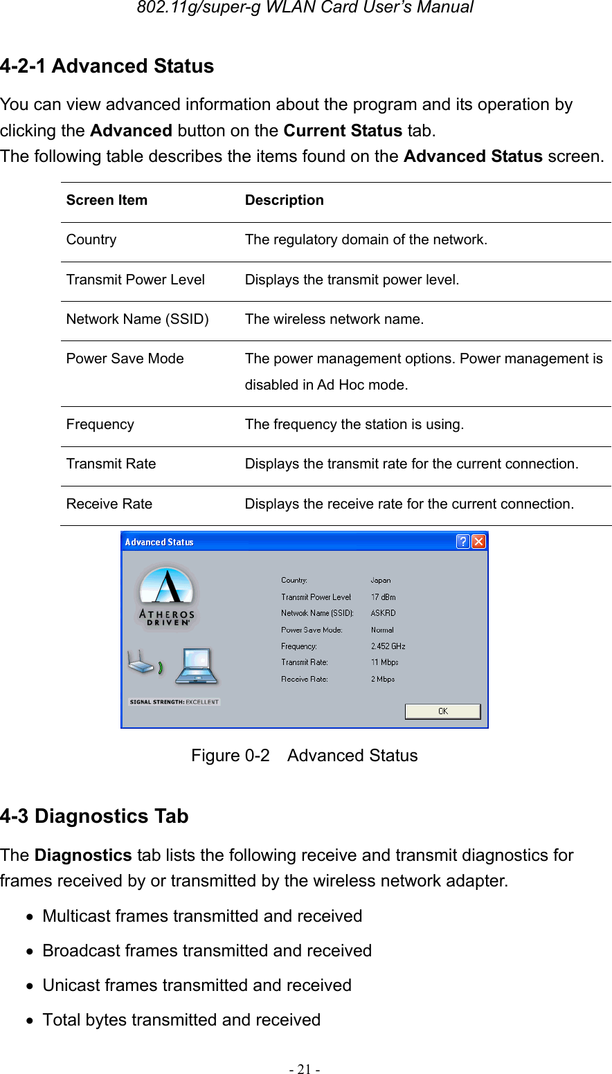
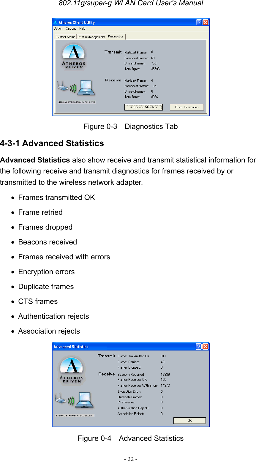
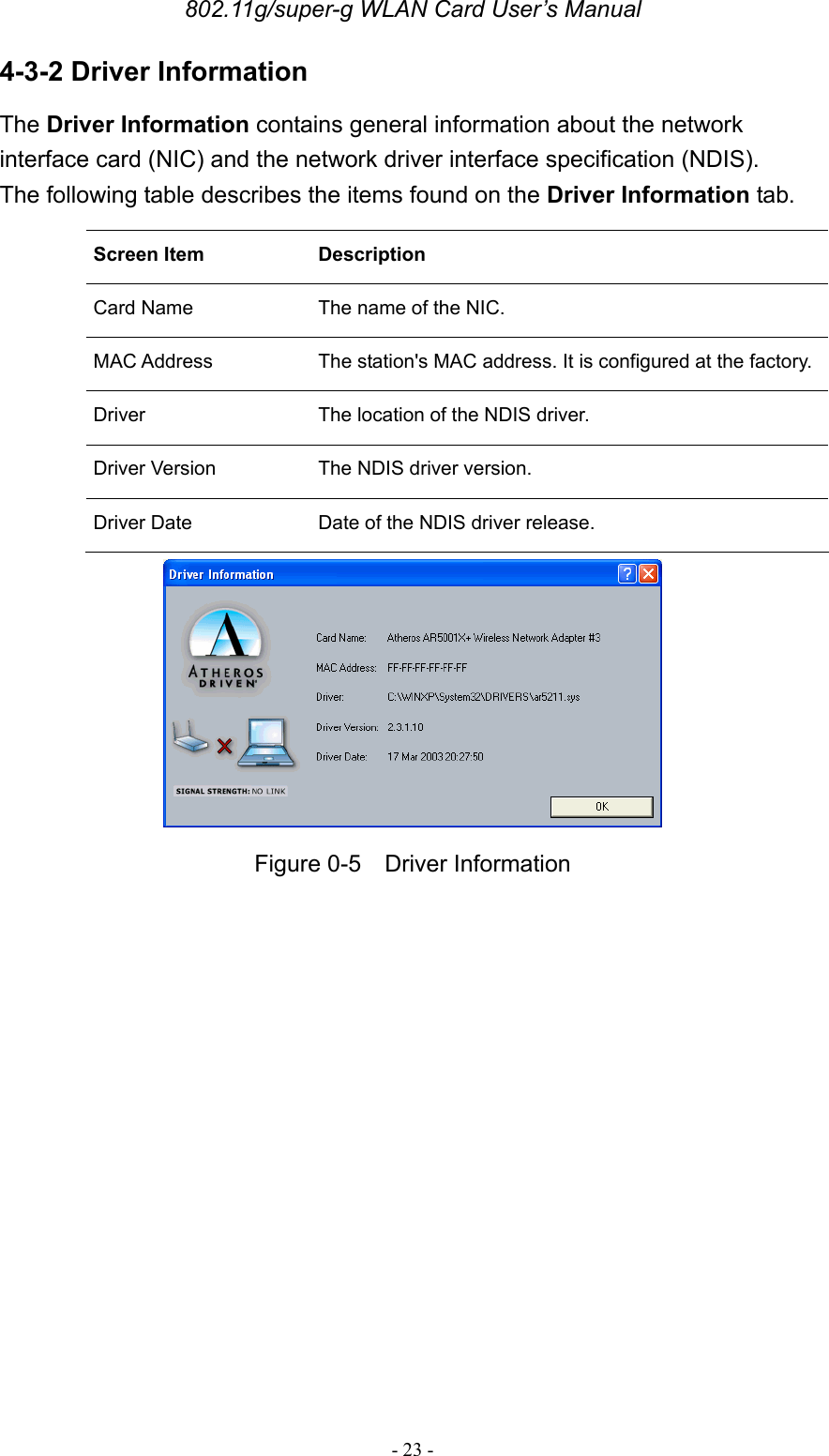
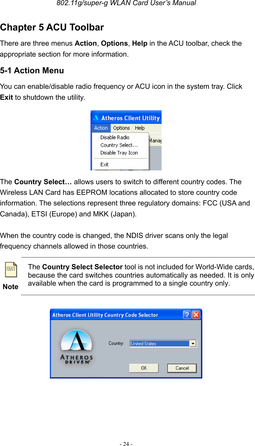
USERS MANUAL
Navigation menu
Upload a User Manual
Namespaces
Wiki Guide
HTML
PDF
Info
Views
User Manual
Discussion / Help
Navigation