Sony Group PCG5A1L Laptop PC with WLAN and Bluetooth User Manual Manual OEM
Sony Corporation Laptop PC with WLAN and Bluetooth Manual OEM
Contents
- 1. Manual OEM
- 2. Manual user
Manual OEM

Intel(R) PRO/Wireless 2200BG User's Guide
Your Intel(R) PRO/Wireless 2200BG Network Connection adapter works with either
802.11b or 802.11g wireless standard. Operating at 2.4 GHz frequency at speeds of up
to 54 Mbps you can now connect your computer to high-capacity existing 802.11b
networks using multiple access points within large or small environments, and also to
high-speed 802.11g networks. Your wireless adapter maintains automatic data rate
control according to access point location to achieve the fastest possible connection. All
your wireless client connections can be easily managed by the Intel(R) PROSet for
Wireless utility. Using the Intel(R) PROSet for Wireless Profile Wizard, you can create
profiles automatically to suite your specific connection requirements. Enhanced security
measures using 802.1x, WPA encryption and authentication, and 128-bit WEP
encryption is standard for both 802.11b and 802.11g.
Introduction to Wireless Networking
Software Installation
Using Intel(R) PROSet for Wireless
Connecting to a Network
Security Overview
Setting up Connection Security
Troubleshooting
Specifications
Glossary
Customer Support
Safety and Regulatory Notices
Warranty
Adapter Registration
Information in this document is subject to change without notice.
(c) 2000–2003 Intel Corporation. All rights reserved. Intel Corporation, 5200 N.E.
Elam Young Parkway, Hillsboro, OR 97124-6497 USA
The copying or reproducing of any material in this document in any manner whatsoever
without the written permission of Intel Corporation is strictly forbidden. Intel(R) is a

trademark or registered trademark of Intel Corporation or its subsidiaries in the United
States and other countries. Other trademarks and trade names may be used in this
document to refer to either the entities claiming the marks and names or their products.
Intel disclaims any proprietary interest in trademarks and trade names other than its own.
Microsoft and Windows are registered trademarks of Microsoft Corporation.
*Other names and brands may be claimed as the property of others.
Intel Corporation assumes no responsibility for errors or omissions in this document. Nor
does Intel make any commitment to update the information contained herein.
September 2003

Back to Contents Page
Wireless LAN Overview: Intel(R)
PRO/Wireless 2200BG User's Guide
About Wireless LAN Technology
● Choosing a WLAN
● Configuring a WLAN
● Identifying a WLAN
● Surveying the Site of Your WLAN
● Factors Affecting Range
A wireless network connects computers without using network cables. Computers use
radio communications to send data between each other. You can communicate directly
with other wireless computers, or connect to an existing network through a wireless
access point. When you set up your wireless adapter, you select the operating mode for
the kind of wireless network you want. You can use your wireless adapter to connect to
other similar wireless devices that comply with the 802.11 standard for wireless
networking.
Choosing a Wireless LAN
Wireless LANs can operate with or without access points, depending on the number of
users in the network. Infrastructure mode uses access points to allow wireless computers
to send and receive information. Wireless computers transmit to the access point, the
access point receives the information and rebroadcasts it to other computers. The
access point can also connect to a wired network or to the Internet. Multiple access
points can work together to provide coverage over a wide area.
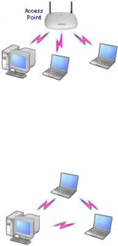
Peer-to-Peer mode, also called Ad Hoc mode, works without access points and allows
wireless computers to send information directly to other wireless computers. Ad Hoc
Mode is only supported in 802.11b and 802.11g networks. You can use Peer-to-Peer
mode to network computers in a home or small office or to set up a temporary wireless
network for a meeting.
Configuring a Wireless LAN
There are three basic components that must be configured for an 802.11 wireless LAN to
operate properly:
● Network Name: Each wireless network uses a unique Network Name to identify
the network. This name is called the Service Set Identifier (SSID). When you set up
your wireless adapter, you specify the SSID. If you want to connect to an existing
network, you must use the name for that network. If you are setting up your own
network you can make up your own name and use it on each computer. The name
can be up to 32 characters long and contain letters and numbers.
● Profiles: When you set up your computer to access a wireless network, the
wireless client manager creates a profile for the wireless settings that you specify.
If you want to connect to another network, you can scan for existing networks and
make a temporary connection, or create a new profile for that network. After you
create profiles, your computer will automatically connect when you change
locations.
● Security: The 802.11 wireless networks use encryption to help protect your data.
Wired equivalent privacy (WEP) uses a 64-bit or 128-bit shared encryption key to
scramble data. Before a computer transmits data, it scrambles the data using the
secret encryption key. The receiving computer uses this same key to unscramble
the data. If you are connecting to an existing network, use the encryption key
provided by the administrator of the wireless network. If you are setting up your
own network you can make up your own key and use it on each computer.
❍ Wi-Fi Protected Access (WPA) is a security enhancement that strongly
increases the level of data protection and access control to a WLAN. WPA
mode enforces 802.1x authentication and key-exchange to strengthen data
encryption. WPA utilizes its Temporal Key Integrity Protocol (TKIP). TKIP
provides important data encryption enhancements that include a per-packet
key mixing function, a message integrity check (MIC) named "Michael", an
extended initialization vector (IV) with sequencing rules, and a also re-keying
mechanism. Using these improvement enhancements, TKIP protects against
WEP's known weaknesses.
❍ Cisco Client Extention (CCX) is a server and client 802.1x authentication
via a user-supplied logon password. When a wireless access point
communicates with a Cisco LEAP-enabled RADIUS (Cisco Secure Access
Control Server (ACS) server), Cisco LEAP provides access control through
mutual authentication between client wireless adapters and the wireless
network and provides dynamic, individual user encryption keys to help
protect the privacy of transmitted data.
Identifying a Wireless Network
Depending on the size and components of a wireless LAN, there are many ways to
identify a wireless LAN:
● The Network Name or Service Set Identifier (SSID): Identifies a wireless
network. All wireless devices on the network must use the same SSID.
● Extended Service Set Identifier (ESSID): A special case of SSID used to identify
a wireless network that includes access points.
● Independent Basic Service Set Identifier (IBSSID): A special case of SSID used
to identify a network of wireless computers configured to communicate directly with
one another without using an access point.
● Basic Service Set Identifier (BSSID): A unique identifier for each wireless device.
The BSSID is the Ethernet MAC address of the device.
● Broadcast SSID: An access point can respond to computers sending probe

packets with the broadcast SSID. If this feature is enabled on the access point, any
wireless user can associate with the access point by using a blank (null) SSID.
Surveying the Site of Your Wireless LAN
Conducting a site survey for your wireless LAN is the most crucial step in the process of
setting up a wireless network. It greatly reduces the amount of troubleshooting you will
have to do once you have the wireless LAN set up and ready for connection testing. To
conduct a site survey, you will need the following tools:
● An access point (or laptop computer) that is set up to be the transmitter. It should
be mounted near and at the same height as the designated location of your
wireless LAN.
● A laptop that will act as the mobile receiver. It must contain your site survey
software.
● An area or building map, which will be used to plot the strength of your signals.
Once you have the tools you need, you are ready to survey the inside of the building.
Launch the site survey software on the mobile receiver laptop and carry it around in the
intended wireless LAN area to test the signal strength. Be sure to also check the signal
strength of each intended access point location. If you encounter problems while
surveying the site, make sure your transmitter laptop is not located on a wall containing
metal, such as an air-conditioning duct, which will interfere with the range of your signal.
Simply move the transmitter and test the signal strength again. For users to have
seamless coverage when moving from access point to access point, the signal levels at
each point must overlap. There is software available that will seamlessly hand off
changing signal levels from one access point to another.
Your building's infrastructure can sometimes interfere with the microwave signal, but
finding the location and cause of the interference will allow you to figure out the best
place to mount your access points for optimal area coverage. Microwave signals travel in
all directions, which means there is one access point for a multi-floor building. However,
the range is highly dependent on the material used to construct the flooring, especially
metal materials. Once your signal strength is strong inside the building, you are ready to
check the strength outside the building. To do so, simply carry the mobile receiver laptop
as far down the street or around the building as you can go without losing significant
signal strength. If possible, you should be aware of the types of networks being used by
the companies on the floors above and below you, so that you can work together in
harmony. With wireless networks, security is very important and if you communicate with
those around you, you are better prepared to select the right channels, as well as the

best location for access points.
Factors Affecting Range
Although access points can transmit signals up to 60 feet away in an area with many
walled barriers or as much as 500 feet away in a large open area, the range is affected
by the following factors:
● Building materials, such as steel and drywall, can shorten the range of the radio
signals.
● Physical layout of the area can interfere with the signals and cause them to be
dropped.
● Electronic noise from cell phones, microwave ovens, or other devices on the same
frequency can interfere with the transmission of the signals.
● Range is inversely proportional to data rate, so the faster that the signals are sent,
the less distance they will travel.
Taking these factors into consideration when you survey the site for your WLAN is key to
providing all of your users with undisturbed mobile connectivity. Using multiple access
points will, of course, reduce the impact of these factors if your area has dividing walls
throughout.
What is a Site Survey?
A site survey is an in-depth examination and analysis of a proposed wireless LAN site.
The purpose of a site survey is to determine the number of access points needed, the
types of antennas needed, and the best placement for those access points and
antennas. Although the goal of a site survey is simple, the means of arriving at that goal
are not. Some of the steps involve taking measurements, but most involve experience,
trial and error, and a little guesswork rather than numbers and figures. When to Perform
a Site Survey Intel® recommends that you perform a site survey prior to installing a
wireless LAN. Site surveys are especially important when:
● You are installing a new site: Evaluate the placement of the access points and
antennas throughout the proposed site.
● You are changing an existing site: When modifying or extending an existing
network structure, re-evaluate the placement of the access points and antennas. If
you need a different level of coverage in some areas, you may need to move,
replace, or supplement access points and antennas.
● You are physically changing the site: Remodeling may introduce new sources of
interference, such as motors and metal structures within the coverage area of the
access point, even if it does not directly effect the sites where the access points
are located.
Elements of an Effective Site Survey
An effective site survey requires four elements. Failure to commit the appropriate time,
money, and energy to accomplish a proper site survey in advance may result in greater
expenditures of money and time later, when problems arise that require repeated
adjustments to the wireless configuration. The three elements of an effective site survey
are:
1. Examine the network usage problems solved by the wireless LAN.
How many clients need a wireless LAN connection? What areas of the site require
wireless LAN connectivity? How many hours each day is wireless LAN connectivity
required? Which locations are likely to generate the largest amount of data traffic?
Where is future network expansion most likely?
2. Study blueprints of the proposed wireless LAN site.
A site blueprint provides a map of the site as well as the location of objects, such
as walls, partitions, and anything else that could affect the performance of a
wireless LAN. Examining the site blueprint prior to conducting the physical walk-
through helps you identify areas in which wireless equipment is likely to perform
well and areas where it is not. Many obstructions are not readily visible and, in
some cases, a room originally built for a specific purpose, such as a radiology lab,
might have been converted into something completely different, such as a
conference room. The blueprint may also show areas proposed for future building
expansion. To prepare for the next step of the site survey, mark possible wireless
device locations on the blueprint and refer to the marked blueprint during the
physical walk-through and inventory.
3. Conduct a physical walk-through and inventory.
The primary purpose of the physical walk-through is to document any items or
materials near a proposed device location that may interfere with reception or
transmission and affect network performance. Document stock and inventory
levels, current environmental conditions and any materials that may interfere with
the wireless LAN.


Back to Contents Page
Software Installation: Intel(R) PRO/Wireless
2200BG User's Guide
Software Installation
Installing Drivers and Intel(R) PROSet for Wireless
Software
See the instructions for your operating system:
● Windows 2000
● Windows XP
Installation under Windows* 2000
Preliminary Notes
The installation instructions in this section are based on the following assumptions:
● The wireless adapter hardware has already been installed in the computer in
accordance with the computer manufacturer's instructions.
● The computer has not been powered on since the hardware installation was
completed.
● No other wireless LAN card is installed in this computer.
To install the driver before installing hardware, use Start > Run and browse to the
file SetupWLD.exe in the path PROW2200\WIN2K on the Intel CD. After running
SetupWLD.exe, shut down the computer and install the hardware. When the computer

restarts, the driver will be automatically installed.
After loading the Windows 2000 operating system, be sure to log in with
administrative rights. If you log in to Windows 2000 without administrative rights, you may
run into problems during the installation.
During initial adapter installation and configuration, it may take up to two minutes for
adapter settings to be confirmed.
Driver Installation
To install driver software in Windows* 2000, follow these steps:
1. Power up the computer in which the wireless adapter hardware has just been
installed.
2. Log in with administrative rights when prompted by Windows 2000.
3. Wait for Windows to detect the newly installed hardware and display the Found
New Hardware Wizard dialog. If Windows does not detect the new hardware, see
Troubleshooting.
4. Insert the Intel CD-ROM into your CD-ROM drive. If the Intel(R) PRO Network
Connections menu screen appears, leave it open and click the Found New
Hardware Wizard dialog to make that the active window.
5. On the Install Hardware Device Drivers screen verify that Search for a suitable
driver for my device (recommended) is selected, then click Next.
6. When the Locate Driver Files dialog appears, verify that the item CD-ROM drives
is checked and click Next.
7. When the Driver Files Search Results dialog appears, indicating that a driver was
found, click Next.
8. On the Network Name screen, click Next to accept the default Network Name
(SSID), or enter a specific SSID for your network, then click Next.
9. On the Data Encryption screen, click Next to accept the default encryption setting
None, or enter specific encryption settings for your network, then click Next.
10. On the Found New Hardware Wizard screen, click Finish. Proceed to install
Intel(R) PROSet for Wireless.
Intel(R) PROSet for Wireless Installation (Required)
Continue with the following steps to install the Intel(R) PROSet for Wireless

wireless configuration utility (required):
Some versions of this product do not support the Intel(R) PRO Network
Connections menu screen for installation of utility software. If the Intel(R) PRO Network
Connections menu screen does not appear, or if it does not have a menu item for
Wireless LAN Adapters, you can start the Intel(R) PROSet for Wireless installer manually
using Start > Run and browsing to the file iSetup.exe in the path
APPS/PROSET/WINXPT32 on the Intel CD supplied with the product. Skip Steps 11 and
12 below and continue with Step 13.
11. On the Intel(R) PRO Network Connections screen, click Wireless LAN
Adapters.
This screen may have been launched in step 4 above. If the screen is not
visible when you close the Found New Hardware Wizard dialog, display it by
removing and re-inserting the Intel CD, or by running autorun.exe from the CD.
12. On the Intel PRO/Wireless LAN Adapters menu screen, click Install Software.
13. On the Welcome to the InstallShield Wizard for Intel(R) PROSet for Wireless
screen, click Next.
14. On the License Agreement screen, after reading the license agreement, select I
accept the terms in the license agreement and click Next.
15. On the Setup Type screen, verify that Typical is selected, then click Next. This is
the recommended setting for a first-time installation.
16. On the Ready to Install the Program screen click Install.
17. After the software is installed on your computer, click Finish. Click Exit to close the
Intel(R) PRO Network Connections screen.
18. To launch Intel(R) PROSet for Wireless, double-click the Intel(R) PROSet for
Wireless icon in the system tray or follow the path Start > Programs > Intel
Network Adapters > Intel(R) PROSet. For additional information on the program,
press F1 or click Help while the program is running.
During initial adapter installation and configuration, it may take up to two minutes for
adapter settings to be confirmed.
Uninstalling Intel(R) PROSet for Wireless
After uninstalling Intel(R) PROSet for Wireless using the "add/remove" feature in

Windows, re-boot the computer. Any current connection remains active (the profile is
active) until the computer re-boots.
Installation under Window* XP
Preliminary Notes
The installation instructions in this section are based on the following assumptions:
● The wireless adapter hardware has already been installed in the computer in
accordance with the computer manufacturer's instructions.
● The computer has not been powered on since the hardware installation was
completed.
● No other wireless LAN card is installed in this computer.
To install the driver before installing hardware, use Start > Run and browse to the
file SetupWLD.exe in the path PROW2200\WINXP on the Intel CD. After running
SetupWLD.exe, shut down the computer and install the hardware. When the computer
restarts, the driver will be automatically installed.
Before proceeding, make sure that you are operating Windows XP with
administrative rights. If you log in to Windows XP without administrative rights, you may
run into problems during the installation.
The Intel(R) PROSet for Wireless utility or the Windows XP wireless configuration
feature can be used to configure wireless network settings. The instructions below
include steps for installing the Intel(R) PROSet for Wireless utility and for turning off the
Windows XP configuration feature. If you do not turn off the Windows XP feature, you will
not be able to use Intel(R) PROSet for Wireless to configure wireless network settings.
For information on how to use the Windows XP feature, see your Windows XP
documentation.
Driver Installation
To install drivers under Windows* XP, follow these steps:

1. Power up the computer in which the wireless adapter hardware has just been
installed.
2. Log in with administrative rights if prompted by Windows XP.
3. Wait for Windows to detect the newly installed hardware and display the Found
New Hardware Wizard dialog. Verify that Install the software automatically
(Recommended) is selected. If Windows does not detect the new hardware, see
Troubleshooting.
4. Insert the Intel CD into your CD drive. The New Hardware Found Wizard
searches for the correct driver files and copies them to your hard drive.
5. On the Network Name screen, click Next to accept the default Network Name
(SSID), or enter a specific SSID for your network, then click Next.
6. On the Data Encryption screen, click Next to accept the default encryption setting
None, or enter specific encryption settings for your network, then click Next.
7. On the Found New Hardware Wizard screen, click Finish. Proceed to disable the
Windows XP wireless configuration feature.
Disable Windows XP Wireless Configuration (Required)
To disable the Windows XP wireless configuration feature so that you can use Intel(R)
PROSet for Wireless for wireless configuration, continue as follows:
Instructions are written for use with the Windows XP Start Menu and Control Panel
Category View, not with "Classic" Start Menu or Control Panel views.
8. Click Start and Control Panel.
9. On the Pick a category screen, click Network and Internet Connections, then
under the heading or pick a Control Panel icon click Network Connections.
10. In the Network Connections window, right-click your Wireless Network
Connection and select Properties.
11. Select the Wireless Networks tab.
12. Click to clear ("deselect") the check box Use Windows to configure my wireless
network settings, then click OK on the Wireless Network tab. Do not click any
other tabs. Continue with the installation of Intel(R) PROSet for Wireless.
Intel(R) PROSet for Wireless Installation (Required)
Continue with the following steps to install the Intel(R) PROSet for Wireless wireless
configuration utility (required):

Some versions of this product do not support the Intel(R) PRO Network
Connections menu screen for installation of utility software. If the Intel(R) PRO Network
Connections menu screen does not appear, or if it does not have a menu item for
Wireless LAN Adapters, you can start the Intel(R) PROSet for Wireless installer manually
using Start > Run and browsing to the file iSetup.exe in the path
APPS/PROSET/WINXP32 on the Intel CD supplied with the product. Skip Steps 13 and
14 below and continue with Step 15.
13. Display the Intel(R) PRO Network Connections screen by removing and re-
inserting the Intel CD, or by running autorun.exe from the CD. Click Wireless LAN
Adapters.
14. On the Intel PRO/Wireless LAN Adapters menu screen, click Install Software.
15. On the Welcome to the InstallShield Wizard for Intel(R) PROSet for Wireless
screen, click Next.
16. On the License Agreement screen, after reading the license agreement, select I
accept the terms in the license agreement and click Next.
17. On the Setup Type screen, select Typical and then click Next. This is the
recommended setting for a first-time installation.
18. On the Ready to Install the Program screen click Install.
19. After the software is installed on your computer, click Finish. Click Exit to close the
Intel(R) PRO Network Connections screen.
20. To launch Intel(R) PROSet for Wireless, double-click the Intel(R) PROSet for
Wireless icon in the system tray or follow the path Start > Programs > Intel
Network Adapters > Intel(R) PROSet. For additional information on the program,
press F1 or click Help while the program is running.
Uninstalling Intel(R) PROSet for Wireless
After uninstalling Intel(R) PROSet for Wireless using the "add/remove" feature in
Windows, re-boot the computer. Any current connection remains active (the profile is
active) until the computer re-boots.
Back to Contents Page
Please read all restrictions and disclaimers.

Back to Contents Page
Troubleshooting: Intel(R) PRO/Wireless
2200BG User's Guide
Troubleshooting
● LAN Utility Conflict Message
● Using a Profile with an incorrect WEP Encryption Key
● Problems with installation
● Users are dropped from the wireless network
● Range decreases as data rate increases
● Signal doesn't pass through a short or thin wall
● Signal strength drops when a cell phone is used in area
● Range is shorter than it should be
● Interference from fluorescent lights
● When too much range is undesirable
● Help Prevent access to wireless networks from outside the building
● Problems with network connectivity
● Checking Adapter Statistics
● Before calling Customer Support
LAN Utility Conflict Message
Message dialog "Another wireless LAN utility is communicating with the Intel(R)
PRO/Wireless LAN adapter. To avoid conflicts, Intel(R) PROSet for Wireless has
temporarily disabled its Profile Management features" is displayed. Refer to Enabling
Intel(R) PROSet for Wireless to manage Your Wireless Connections for information.
Using a Profile with an incorrect WEP Encryption Key
When connected to an access point using a profile with an incorrect WEP key encryption,
the task tray icon and the General page will both indicate good signal strength and that
you are associated with the AP. However, when you attempt to send data to the AP
using this profile, because of the incorrect WEP key encryption, authentication cannot be
established to acquire an IP address from the AP to allow data transfer.
Refer to the following WEP encryption and authentication settings.
Open Authentication with an incorrect WEP 64 or 128-bit encryption key:
● A profile with an incorrect WEP encryption key will allow the wireless adapter to
associate with the access point.
● No data transfer
Open Authentication with no WEP encryption:
● Allows association to an access point
● Data transfer is allowed
Shared Authentication:
● Associated to an AP always allows data transfer.
Problems with installation
Windows does not detect the wireless adapter:
1. Remove and re-install the adapter.
2. Uninstall and reinstall the adapter's drivers.
Users are dropped from the wireless network
Suggested causes and solutions:
● Find out if a person or workgroup moved or if the building has been rearranged.
● If two or more users are seated too close to each other, performance can suffer.
Instruct your users to space themselves a small distance apart to keep receivers
from being overloaded.
● Delivery trucks with very large metal sides can affect performance by reflecting
destructive signals back into a building. If you have an installation that includes a
shipping dock, check to see if the problem coincides with the arrival of large
trucks.
● Personal “systems” can also interfere with your network. Wireless speakers,
cordless earphones, some Bluetooth devices, and similar systems can be the
source of an infrequent but hard to find the problem. Some systems do not conform
to wireless regulations. Shut off suspect devices or remove them from the area.
● If possible, remove and reinstall your new software. Conflicts with other resident
software packages are always a possibility, and they are not always the fault of the
newest addition. Sometimes just starting over fixes the problem.
● Swap units around. Does your problem follow the changed units, or is it unique to a
specific location? If it follows the product, the swapped unit could be damaged, or
improperly configured. If the problem stays with the location, try to find out what is
different about that particular room or area.
Range decreases as data rate increases
This is a normal condition. Range is inversely proportional to data rate: the faster the
data, the shorter the range. This has to do with the modulation technology used. Very
fast data rates require extremely complex signal waveforms, where even minor
distortions can result in data errors. Slower data rates are much more tolerant, and
consequently will get through even in the presence of some amount of noise,
interference, distortion and echo.
Signal doesn't pass through a short or thin wall
Range is highly dependent on the physical environment. In a line-of-sight location, with
elevated and calibrated antennas, range predictions are quite accurate. This is not true in
a “typical” office building, where the walls may be simple drywall (which is almost
transparent to microwaves), or could be plaster with metal underneath. Most sites are
somewhere between these two extremes, and consist of a mixture of surfaces. You can’t
tell what is inside a wall by just looking at it, and we can’t tell you exactly what distance
you will achieve. Consider published range information to be typical, average, common
or usual. Do not expect it to be exact.
Signal strength drops when a cell phone is used in the area
Range also depends on the electronic environment. If other equipment that could cause
interference is nearby, the range of your transceiver could vary widely, and could change
suddenly when the other equipment activates. This is particularly true for 802.11b
installations, which share their frequencies with microwave ovens, cordless phones,
wireless hi-fi speakers, electronics toys and similar devices. Try to keep your system
away from other transmitters, and from other sources of electrical noise, such as large
motors, spot welders, and similar “electronically noisy” devices.
Range is shorter than it should be
Repeat some tests late in the evening, or on a weekend, when there may be less
interference. However, some users leave their networks turned all the time so this test is
not foolproof. By all means, try more than one channel. Your range problem may just be
a nearby user whose system uses your present test channel.
Interference from fluorescent lights
If you mount an access point close to fluorescent light fixtures, the lamp glow appears
constant, but inside the lamp tube, ionization appears and disappears 120 times a
second. This can modulate or “chop” an incoming signal and interfere with reception.
When too much range is undesirable
Too much range is not necessarily a good thing. At first it would appear that you would
want as much range as possible, but with the increase in range comes an increase in
interference potential, as your unit hears not only your other units but also manages to
hear the systems of other companies up and down the street. If you have a large
installation, you will also wind up with more than one access point using the same
channel. If a remote unit hears two or more access points, this will slow the network.
Help Prevent access to wireless networks from outside the building
Excess transmit range presents a special reverse problem. For example, putting an
access point adjacent to a second floor bay window invites anyone with the right software
on the street below to pick up and enjoy all network transmissions. We discuss some
possible solutions to this problem further on.
Problems with Network Connectivity
If you cannot connect to the wireless network, try the following:
Check Network Settings
1. From the General page, check that the Network Name (SSID) and operating mode
are correct. If the laptop is configured for ad hoc networking, make sure that the

channel is correct.
2. To correct these settings, click the Networks tab.
3. Select the profile being used.
4. Click the Edit button and make the changes.
Check Security Settings
1. From the General page, check that the security settings are correct.
2. To correct the security settings, click the Networks tab.
3. Select the profile being used.
4. Click the Edit button.
5. Click the Security tab. Make sure that the settings for WEP encryption are correct.
Checking Adapter Statistics
Adapter Statistics
If the adapter is communicating with an access point (infrastructure mode) or other
computers in peer-to-peer mode, click the Statistics button in the Troubleshooting tab to
display the current information about how well the adapter is transmitting and receiving
information.
Before calling Customer Support
Make a note of the following answers before calling customer support:
● From the General tab, view the adapter's connection details. Check that it is
associated with an access point, and the quality and strength of the signal.
● From the General page, click the Details button and check what revision of
software and hardware or other LAN software are you running?
● How many remote units do you have talking to each access point?
● What channels are you using, and how are they dispersed?
● How much coverage overlap is there between access points?
● How high above the floor are the access points mounted?
● What other electronic equipment is operating in the same band?
● What construction materials are used in wall and floors?
Back to Contents Page


Back to Contents Page
Connecting to a Network: Intel(R)
PRO/Wireless 2200BG User's Guide
Connecting to a Network using Intel(R) PROSet for
Wireless
● Enabling Intel(R) PROSet for Wireless to manage Your Wireless Connections
● How to access Advanced Settings
● System Wide Advanced Settings
● Intel(R) PROSet for Wireless Configuration Service
● Scanning for Available Networks
● Connecting to a Network Using an Access Point
● Connecting to a Peer-to-Peer (Ad Hoc) Network
● Switching the Radio Off and On
● Disable the Radio from Windows
● Viewing Adapter Advanced Settings in Windows
Enabling Intel(R) PROSet for Wireless to manage Your
Wireless Connections
If you are using Windows XP as your wireless manager the following described how to
enable Intel(R) PROSet for Wireless as your wireless manager.
1. From the desktop, Click the Start button > Control Panel. Double-click Network
Connections, right-click Wireless Network Connection, then click Properties.
2. In Wireless Network Connection Properties, Click the Wireless Network tab.
3. Verify that the Use Windows to configure my wireless network settings checkbox is
clear (unchecked).
4. Double-click the Intel(R) PROSet for Wireless icon in the desktop task tray.
5. If you have previously setup your profiles, click the Networks tab. The profile list

should display available networks to connect to. If no profiles have been
established, refer to Creating a New Profile for more information.
How to access Advanced Settings
Use the Advanced Setting to configure your network connection preferences, and profile
management option.
To access the Advanced Settings:
1. From the General page, click the Networks tab.
2. Click the Advanced button.
Advanced Settings:
● Auto-connection
● Connection preference
● Infrastructure wireless mode selection
● Profile management
● 11b/11g mixed environment protection protocol
● Advanced Security
● Import/Export Button
Refer to System Wide Settings for more about profile management options in Advanced
Settings.
System Wide Advanced Settings
Profile Management Options
The following Profile Management options can be found in Advanced Settings.
Display available networks when not associated: When cleared, disables the Intel(R)
PROSet for Wireless wireless manager dialog listing the available networks. When
checked, the Intel Configuration Service running in the background automatically
displays available networks not listed in the Profile List. This method provides automatic
connection to available networks in the range of your wireless adapter. The Configuration
Service constantly monitors your wireless adapter's connection status. If no matching
profiles are found in the Profile List for a network, a dialog automatically displays the
available network access points and computers (ad hoc mode) within range of the
wireless adapter. The Configuration Service can also be used if there is more than one
wireless adapter installed using 802.11b bands. When the Intel Configuration Service
dialog is displayed, listing the available networks, checking "Don’t show this again"
option, will prevent the dialog from displaying again if the adapter becomes
unassociated. The Configuration Service will continue to function and attempt to connect,
using a profile from the Profile List, or to an available network depending on the selection
mode. This means that if Connect Using Preferred Profiles Only is selected and no
matching profile is found, then the adapter will remain unassociated. You can still use the
Connect button from the Networks tab to connect to an available network.
Notify when disabling profile management features:
Check: If Intel(R) PROSet for Wireless is currently managing your wireless adapter a
message dialog displays "Windows XP is managing your profiles" if Windows XP Zero
Configuration becomes enabled.
● Select yes, Intel(R) PROSet for Wireless will manage the wireless adapter.
● Select No, Windows XP will manage the wireless adapter.
If any other wireless manager (not Windows XP wireless manager) becomes enabled the
message dialog displays "Another wireless LAN utility is communicating with the Intel(R)
PRO/Wireless LAN adapter. To avoid conflicts, Intel(R) PROSet for Wireless has
temporarily disabled its Profile Management features."
Clear: If Intel(R) PROSet for Wireless is currently managing your wireless adapter you
will not be notified in the event that Windows XP Zero Configuration or any other wireless
manager becomes enabled.
In the event that Windows XP Zero Configuration is enabled, and this box is cleared, or
you answer no to the above question, the Connect button on the Profile page cannot be
used to connect to any available networks. The Scan button can be used to scan for
available networks. However, the Connect button is non-functioning when used to
connect to an available network.
● Ad hoc mode is disabled. The Connect button in the ad hoc connect dialog is non-

functioning.
● Task tray icon menu: Launching an ad hoc profile and applying a profile from the
task tray menu is not available.
Notify when Windows XP Zero Configuration is enabled:
Check: If the box is checked, when Intel(R) PROSet for Wireless starts up, a message
dialog displays "Windows XP is managing your profiles" if Windows XP Zero
Configuration is enabled, indicating that Windows XP is currently configured to manage
the wireless adapter. Do you wish to disable Windows XP management and let Intel(R)
PROSet for Wireless manage your wireless network?
● Select Yes - Intel(R) PROSet for Wireless will manage the wireless adapter.
● Select No - Windows XP will manage the wireless adapter.
Clear: If the box is cleared, when Intel(R) PROSet for Wireless starts up, you will not be
notified in the event that Windows XP Zero Configuration wireless manager is enabled.
Enable Profile Management Features: If the box is checked, it indicates that Intel(R)
PROSet for Wireless is configured to manage your wireless adapter. If cleared, Windows
XP is the wireless network manager.
Intel(R) PROSet for Wireless Configuration Service
The Configuration Service feature operates in background to automatically display
available networks not listed in the Profile List. This method provides automatic
connection in a 2.4 environment to available networks in the range of your wireless
adapter. The Configuration Service constantly monitors your wireless adapter's
connection status. If no matching profiles are found in the Profile List for a network, a
dialog automatically displays the available network access points and computers (ad hoc
mode) within range of the wireless adapter. The Configuration Service can also be used
if there is more than one wireless adapter installed using 802.11b band.
The Configuration Service features:
● The Configuration Service is launched when you log on to your computer.
● No active profile switching will be performed. Once the adapter is associated with
the access point, if a higher priority profile becomes available, no switching will
occur.
● The Configuration Service is only available if Intel(R) PROSet for Wireless is
installed.
● If a connection to an access point cannot be made using any of the profiles in the
Profile List, a dialog will display the available networks.
● If there are multiple profiles listed for an available network, a dialog box will list the
profiles for you to choose from.
● If an available network is detected with WEP encryption and authentication, a
dialog for setting up WEP encryption displays before the connection is made.
The Configuration Service can be used in two ways:
1. Connect to available network using profiles only: In this mode the Configuration
Service attempts to connect to a network access point using profiles from the
Profile List only. If no matching profile is found, a dialog appears that lists the
available networks. You can also close this dialog without connecting by clicking
the Cancel button. The adapter will remain unassociated, and the list of available
networks will NOT be displayed again unless another available network is
detected. This mode is set in the Advanced Setting options.
2. Connect to any available network if no matching profile found: In this mode the
Configuration Service attempts to connect to a network access point first using
profiles from the Profile List. If no matching profile is found, the Configuration
Service automatically connects to any available network. This mode is set in the
Advanced Setting options.
Enabling Automatic Connection
The Configuration Service also monitors for the "resume status" after a laptop computer
suspend event. When this occurs, the Configuration Service will re-enable the automatic
connection service.
These features can be enabled again after rebooting your computer or after a suspend
and resume cycle.
Features affected when another profile management application is detected
For AAA Client:
Select OK, and the AAA Client application will manage the adapter. The current

connection will continue with the affected Intel(R) PROSet for Wireless features show
below. To avoid conflicts, the Intel(R) PROSet for Wireless profile management features
have been temporarily disabled. To re-enable these features, first disable the other LAN
utility and then either:
1. Re-enable from Intel(R) PROSet for Wireless Advanced Settings.
2. Resume after a computer suspend.
3. Reboot the computer.
NOTE: AAA Client Wireless Manager - If Intel(R) PROSet for Wireless detects
another wireless AAA client manager, a notification dialog displays, if you choose
"OK" on this dialog, the Intel(R) PROSet for Wireless profile management
features are automatically disabled. The Advanced Setting "Notify when
disabling profile management features" check box must be checked in order
to display the notification dialog if Windows XP Zero Configuration in not
enabled. The default setting is enabled (checked).
For Windows XP Zero Configuration:
● Select Yes, to disable Windows XP Zero Configuration. Intel(R) PROSet for
Wireless will continue to manage the adapter.
● Select No, Windows XP will manage the adapter. The current connection will
continue with the affected Intel(R) PROSet for Wireless features show below. You
can also prevent the dialog from being displayed again, in which case Windows XP
Zero Configuration will automatically manage the wireless adapter. The notification
dialog can be re-enabled from the Advanced Settings options.
Affected Intel(R) PROSet for Wireless features:
● The Connect button on the Profile page is non-functioning.
● The Scan button can be used to scan for available networks, however, the Connect
button is non-functioning when used to connect to an available network.
● Ad hoc mode is disabled. The Connect button in the ad hoc connect dialog is non-
functioning.
● Task tray icon menu: Launching an ad hoc profile and applying a profile from the
task tray menu is not available.

NOTE: If the buttons described above are used, the following message displays:
"Another wireless LAN utility is communicating with the Intel(R) PRO/Wireless
LAN adapter. To avoid conflicts, Intel(R) PROSet for Wireless has temporarily
disabled its Profile Management features."
Scanning for Available Networks
A fast way to connect to a network is to use the Scan button to search for a network
access point in range of your wireless adapter. When a network is found, you can
instantly connect without a profile or create a new profile.
NOTE: Profiles with the Enable Auto-Import feature enabled will also be
displayed in the profile list of available networks. Refer to Automatic Profile
Distribution for more information.
To scan for available networks:
1. From the General page, select the wireless adapter on the left side pane.
2. Select the Networks tab.
3. Click the Scan button.
4. The Available Networks dialog displays the names of the available networks. Click
the Refresh button to refresh the list of available networks.
5. Select the network from the list, and click the Connect button.
6. Select the network profile name with <no profile> shown, and click the Connect
button.
7. Click the No, connect me directly without creating a profile option. Note, you
can click Yes, create a profile for this network now to create a profile to be used
later.
NOTE: If the selected network has 802.1x authentication, you must first create a
profile using the Profile Wizard. However, if the network has no WEP security
(Open), WEP 64 or 128-bit encryption, or WPA-PSK, you can enter the required
security settings in the dialog that displays after clicking the Connect button.
Then a one time connection without a profile can be made.

● The selected network has WPA security settings: If the selected
network has 802.1x authentication security settings, after clicking the
Connect button, the Profile Wizard Advanced Security page will
display. From this dialog you can enter the 802.1x settings and
connect to the network.
● The selected network has no (Open) WEP security settings: If the
selected network has no security (Open). Click the Connect button to
connect to the network.
● The selected network has WEP or WPA-PSK security settings: If
the selected network has WEP encryption security settings, after
clicking the Connect button, the Profile Wizard Advanced Security
page will display. From this dialog you can enter the WEP security
settings and connect to the network.
8. Click OK to connect to a network.
Connecting to a Network Using an Access Point
An infrastructure network consists of one or more access points and one or more
computers with wireless adapters installed. Each access point must have a wired
connection to the Local Area Network (LAN).
You can connect to a network by first creating a new profile using the Profile Wizard,
then selecting that profile to connect to the network access point using the Connect
button. You can also connect to a network, by using the Scan button. Refer to Creating a
New Profile for more information.
Connecting to a Peer-to-Peer (Ad Hoc) Network
Connect or Start an Ad Hoc Network
Start an Ad Hoc Network
Ending an Ad Hoc Session
Creating an Ad Hoc Profile Using the Profile Wizard

In peer-to-peer (ad hoc) mode, you can send and receive information to other computers
in an ad hoc network. All wireless clients in the ad hoc network must use the same
network name (SSID) and channel number. For a list of allowed 802.11b ad hoc
channels, refer to the Adapter Settings for more information.
NOTE: While scanning with an ad hoc profile set to a specific transmit channel, if
an ad hoc network is found on another channel, you will be connected using the
new channel. The new channel number is displayed in the Adapter Settings.
Connect to an Ad Hoc Network
NOTE: For information about connecting to an ad hoc using a profile, refer to
Create an Ad Hoc Profile using the Profile Wizard.
Connect to an ad hoc network using a profile
● Select an ad hoc profile from the Profile List and click the Connect button. This
method uses a pre-defined ad hoc profile created by the Profile Wizard. When
connecting to an ad hoc network, the transmit channel established by the first
computer is used. This channel may be different than the one selected when the
ad hoc profile was created by the Profile Wizard.
Join an ad hoc network without a profile
● Join a one-time ad hoc session without a profile. This method does not use a pre-
defined profile. To connect to any ad hoc network, click the Scan button to scan for
any ad hoc networks, enter the password (SSID), then click the Connect button to
connect. When joining an ad hoc network, the transmit channel established by the
first computer is used.
Start an Ad Hoc Network
You can start an ad hoc network by using your computer as a wireless station. This
method uses your computer's SSID to establish the ad hoc network for other users to
connect to. When you are the originator of an ad hoc network, all other users must use
the channel and SSID.
Ending an Ad Hoc Session
To end an ad hoc session, click the default profile in the Profile List and click the Close
button.
Creating an Ad Hoc Profile Using the Profile Wizard
The following describes how to create a new ad hoc profile using the Profile Wizard and
connect to an ad hoc network
General Settings
1. From the General page, click the Networks tab.
2. Click the Add button. The General Settings dialog displays.
3. Enter a profile name in the Profile Name field.
4. Enter the network SSID, in the Network Name (SSID) field.
5. Click Ad hoc operating mode.
6. Click Password protect this profile to set a profile password.
7. Click Next.
Security Settings
8. Select either None, WEP for the data encryption.
9. If WEP is selected, select either 64 or 128-bit for the Encryption Level.
10. Select the key index 1, 2, 3 or 4.
11. Enter the required pass phrase or hex key.
12. If the Password Protection checkbox was checked on the General settings page,
then
click Next to display the Password page.
Password Protection Settings
13. Click the Password protect this profile checkbox.
14. Enter a password in the Password field.
15. Reenter the same password in the Confirm New Password field.
16. Click the Back button to change or verify the settings or click Finish when you
have completed the profile settings and return to the Networks page.
Connect to the Network

17. Changing the default transmit channel from the Adapter tab: Unless the other
computers in the ad hoc network use a different channel from the default channel,
there is no need to change the default channel. If you want to change the default
channel, click the Adapter tab, and click Configure under Ad Hoc Channel
Selection. Choose the operating band select a channel. Click OK to save the
setting.
18. Select the Networks tab
19. After creating the new profile, click the profile in the Profile List. Profiles using ad
hoc mode are indicated by a computer icon next to the profile name.
20. Click the Connect button to connect to the ad hoc network.
Switching the Radio Off/On
When your computer is switched on, if the radio is enabled it is constantly transmitting
signals. In certain situations, such as landing or takeoff of an airplane, the radio signals
may need to be turned off, if not these signals may cause interference. The following
describes how to use your keyboard (if this option is available) and Intel(R) PROSet for
Wireless to switch the radio on or off.
The radio can be enabled or disabled from your computer keyboard, the task tray
wireless menu option and from Intel(R) PROSet for Wireless. The current status of the
radio is displayed in the task tray wireless icon and on the General page.
Using the optional hardware radio on/off switch
The radio can enabled or disabled from your keyboard, or from an external hardware
switch if these options are available. Refer to your computer manufacturer for more
information. Intel(R) PROSet for Wireless displays the current state of the radio on the
General page if one of these option is installed.
Using Intel(R) PROSet for Wireless to switch the radio on/off
The radio can be switched on or off from General page in Intel(R) PROSet for Wireless.
The current state of the radio is displayed in the wireless adapter task tray menu option.
The General page also displays the current state of the radio if the hardware option is
installed.
Switching the radio On/Off

Note: When your laptop is switched on, the radio is constantly transmitting signals. In
certain situations, such as in a plane, signals from the radio may cause interference.
To switch the radio OFF: From the General page; click the Off button next to Switch
Radio On/Off.
● The wireless adapter is not associated with the network when the radio is off.
● Intel(R) PROSet for Wireless can be used to edit or add profile contents when the
radio is off.
To switch the radio ON: From the General page; click the On button next to Switch
Radio On/Off.
When the radio is on, an attempt will be made to associate with the network access point
using the last profile. If the adapter cannot connect to the access point, the Configuration
Service will attempt to find an available network. Refer to Configuration Service for more
information.
Switching the radio on or off from the Task Tray menu option
Right-click the wireless icon in the task tray and select the wireless adapter being used.
Depending on the previous state of the radio, select Switch Radio Off (radio is already
ON, select to turn OFF) or Switch Radio On (radio is already OFF, select to turn ON).
Disable the Radio from Windows
The radio can be disabled (made non-functional) via the Windows operating system
using Device Manager.
Windows XP/2000
1. From your desktop, right-click My Computer and click Properties.
2. Click the Hardware tab.
3. Click the Device Manager button.
4. Double-click Network adapters.
5. Right-click the installed wireless adapter in use.

6. Choose Disable from the pop-up menu.
7. Click OK.
Viewing Adapter Advanced Settings in Windows
The following advanced options are available in the Windows Device Manager Advanced
tab if Intel(R) PROSet for Wireless is not installed. If PROSet for Wireless is installed the
Advanced tab displays the Open button. Selected this button to open PROSet for
Wireless.
To access the Advanced options:
1. From your desktop, right-click My Computer and click Properties.
2. Click the Hardware tab.
3. Click the Device Manager button.
4. Double-click Network adapters.
5. Right-click the name of the installed wireless adapter in use.
6. Select the Advanced tab.
Advanced tab option under Windows XP and 2000:
● Ad Hoc Transmit Power - Set 802.11b ad hoc output power level of the wireless
adapter.
● Mixed mode protection - RTS/CTS enabled: (Default setting). Use this mode to
avoid collisions in mixed mode environments where the 802.11g and 802.11b
clients cannot hear each other. CTS-to-self enabled: This mode improves
performance in mixed mode environments where 802.11g and 802.11b clients are
in close proximity and can hear each other. This option can also be set in
Advanced Settings.
● Power Management - Set a balance between the computer's power source and
the battery.
● Wireless Mode - Select the wireless mode (modulation type) for date rate. The
default setting is "802.11g and 802.11b." This option uses both 11 Mbps and 54
Mbps date rate. Other options are, "802.11g only" and "802.11b only."
Back to Contents Page


Back to Contents Page
Using PROSet Profiles: Intel(R) PRO/Wireless
2200BG User's Guide
Using Intel(R) PROSet for Wireless Profiles
● Setting up Windows Network Profiles
● Profile Connection Preferences
● Transmit Data Rates and Access Points
● Creating a New Profile
● Importing and Exporting Profiles
● Setting a Profile Password
● Automatic Profile Distribution
● Editing an Existing Profile
● Deleting a Profile
● Connecting to a Network without a Profile
● Connecting to a Network if a Blank SSID displays
● Loading a Profile from the Task Tray
Setting up Windows Network Profiles
A profile is a saved group of network settings. Profiles are displayed in the Profile List in the
wireless client manager General page. Profiles can be arranged in order of network connection
priority. You can connect to one network using the first profile in the Profile List, then
automatically connect to another network using the next profile. This allows you to stay connected
while roaming freely from one wireless network to another. Although you can assign multiple
profiles to a single network, you can only use one profile per connection. To add a new profile,
use the Profile Wizard sequence of dialogs to configure the profile contents. The following
example uses all of the Profile Wizard dialogs. Some settings may not be required for all profiles.
Refer to the following to setup profile connection preferences:
Profile Connection Preferences

To access the profile connection preference option:
1. From the General page, click the Networks tab.
2. Click the Advanced button.
3. Under the Auto-connection heading, click the one of the following options:
● Connect to available networks using profiles only (Default setting): Use the profiles in
the Profile List to connect to any available network.
● Connect to any available network if no matching profile is found: Connect to any
available network without using a profile from the Profile List.
● Connect to any network based on profiles only (Cisco Mode): Connect to any
available network access point using profiles enabled for Cisco CCX (version 1) mode. This
mode allows connection to access points that support multiple and blank network names
(SSIDs).
❍ Enable Mixed-Cell (Requires Cisco CCX options): Select this Advanced Settings
check box to allow the wireless LAN adapter to communicate with mixed cells. A
mixed cell is a wireless network in which some devices use WEP and some do not.
The option Enable Cisco-Client eXtentions in the Profile Wizard General Settings
page must be enabled for mixed cell support.
4. Click OK to save the setting and return to the previous dialog.
Transmit Data Rates and Access Points
To achieve the optimum transmit data rate it is important to identify the type of access point that
the wireless adapter is connecting to. The Advanced Settings provide the mode selections to
optimize your operating environment.
Infrastructure Mode
The following describes how the wireless preference modes operate using Infrastructure mode.
The adapter can operate in three modes:
● Connect to 802.11g and 802.11b: This is the default setting. The adapter will search for
either 11g or 11b access points using data transmit rates of 1, 2, 5.5, 6, 9, 11, 12, 18, 24,
36, 48, or 54 Mbps. This connection defaults to 11g access points. The Available Networks
list displays all 11b and 11g access points.
● Connect to 802.11g only: The adapter will search for a 11g access point only using data
transmit rates of 1, 2, 5.5, 6, 9, 11, 12, 18, 24, 36, 48, or 54 Mbps. The Available Networks
list displays only 11g access points.
● Connect to 802.11b only: The adapter will search for the best 11b and 11g access points
using data rates of 1, 2, 5.5, or 11 Mbps. The Available Networks list displays any 11b and
11g access point.
Access Point and Client Combinations
The following table shows compare the adapter wireless preference mode, and the transmit date
rates using a specific type of access point. The wireless mode (Modulation type) options
determine the discovered access points displayed in the Scan list (Available Networks dialog).
11b Access Point
Wireless Mode Scan List Connect Transmit Data Rates
11g and 11b Yes Yes 1, 2, 5.5, or 11 Mbps
11b only Yes Yes 1, 2, 5.5, or 11 Mbps
11g only No No None
11g (11g and 11b) Access Point
Wireless Mode Scan List Connect Transmit Data Rates
11g and 11b Yes Yes 1, 2, 5.5, 6, 9, 11, 12, 18, 24, 36, 48, or 54
Mbps*.
11b only Yes Yes 1, 2, 5.5, or 11 Mbps
11g only Yes Yes 1, 2, 5.5, 6, 9, 11, 12, 18, 24, 36, 48, or 54
Mbps*.
11g (11g only mode) Access Point**
Wireless Mode Scan List Connect Transmit Data Rates
11g and 11b Yes Yes 1, 2, 5.5, 6, 9, 11, 12, 18, 24, 36, 48, or 54
Mbps*.
11b only No No None
11g only Yes Yes 1, 2, 5.5, 6, 9, 11, 12, 18, 24, 36, 48, or 54
Mbps*.
Note: (*) depends on the signal strength and quality. Use RTS/CTS (Default setting) to avoid
collisions in mixed mode environments where the 11g and 11b clients cannot hear each other.
Use CTS-to-self to improve performance in mixed mode environments where 11g and 11b clients
are in close proximity and can hear each other.
Note: (**) Because 11b clients cannot connect to this access point mixed mode protection
(RTS/CTS or CTS-to-self) is not used.
Ad Hoc Mode

The following summarizes how the modulation settings operate using ad hoc mode.
Ad Hoc Initiator Ad Hoc Joiner Action Comments
11b-only 11b-only Basic rates (1, 2, 5.5, or 11 Mbps) 11b-only
11g-only Down scale basic rates, turn on protection* (1, 2, 5.5, or 11 Mbps) 11b and 11g
11b and 11g Basic rates (1, 2, 5.5, or 11 Mbps) 11b and 11g
11g-only 11b-only Does not apply to Intel(R) PRO/Wireless 2200BG adapter. For other cards - down scale basic rates, turn on protection* (1,
2, 5.5, or 11 Mbps)
11b and 11g
11g-only Basic rates (1, 2, 5.5, 6, 9, 11, 12, 18, 24, 36, 48, or 54 Mbps) 11g-only
11b and 11g Upscale) basic rates (1, 2, 5.5, 6, 9, 11, 12, 18, 24, 36, 48, or 54 Mbps) 11g-only
11b and 11g 11b-only Basic rates, turn on protection* (1, 2, 5.5, 6, 9, 11, 12, 18, 24, 36, 48, or 54 Mbps) 11b and 11g
11g-only Downscale basic rates, turn on protection* depends on initiator (1, 2, 5.5, or 11 Mbps) 11b and 11g
11b and 11g Basic rates, turn on protection* depends on initiator (1, 2, 5.5, 6, 9, 11, 12, 18, 24, 36, 48, or
54 Mbps)
11b and 11g
Note: (*) See Viewing Adapter Advanced Settings in Windows - Use "RTS/CTS enable" (Default
setting) to avoid collisions in mixed mode environments where the 11g and 11b clients cannot
hear each other. Use "CTS-to-self enable" to improve performance in mixed mode environments
where 11g and 11b clients are in close proximity and can hear each other.
Ad Hoc Transmit Rates Overview
The following describes how the wireless preference modes operate using Ad Hoc mode. The
adapter can operate in three modes:
● Connect to 802.11g and 802.11b: mixed mode (default setting). The adapter will search
for either 11g or 11b access points using data transmit rates of 1, 2, 5.5, 6, 9, 11, 12, 18,
24, 36, 48, or 54 Mbps. This connection defaults to 11g access points. The Available
Networks list displays all 11b and 11g access points.
● Connect to 802.11g only: The adapter will search for a 11g access point only using data
transmit rates of 1, 2, 5.5, 6, 9, 11, 12, 18, 24, 36, 48, or 54 Mbps. The Available Networks
list displays only 11g access points.
● Connect to 802.11b only: The adapter will search for the best 11b and 11g access points
using data rates of 1, 2, 5.5, or 11 Mbps. The Available Networks list displays any 11b and
11g access point.
When different modulation settings are used in ad hoc mode, they influence the computer in the
following ways:
● It determines to which ad hoc network we are allowed to connect to.
● It determines whom we show in our scan list.
A station in an ad hoc network constantly adapts itself to the current situation in the ad hoc
network as far as other stations capabilities are concerned. Updating of the supported transmit
data rates is done in the following way:
Only the basic rates change. Supported rates of a station never change. At all times the basic
rates advertised by stations in an ad hoc network should be the same, and should reflect the set
of basic rates supported by every station in this ad hoc network. Since basic rates is the actual
information used by a station to decide if it can join the ad hoc network then this is enough to
determine if a station can or cannot connect to this ad hoc network.
Mixed Mode
Mixed mode stations (802.11g and 802.11b) are able to join any ad hoc network they hear.
Joining an ad hoc network
● Join an 11b ad hoc network only – keep the supported rates and update the basic rates to
fit the ad hoc network you are joining. Protection (RTS/CTS or CTS-to-self) is on.
● Join an 11g ad hoc network only – keep the supported rates and up scale the basic rates
advertised in the beacons. Note that this is not good because the station ceases being a
“mixed mode” and become an 11g only station.
● Join an 11a and 11b ad hoc network only – keep the supported rates and update the basic
rates to fit the ad hoc network you are joining.
Initiating an ad hoc network
When initiating a mixed mode ad hoc network the default rates for mixed mode is: 1, 2, 5.5, 11, 6,
12, 18, 24, 36, 48 and 54 Mbps with rates 1, 2 as basic. When other stations join in, the basic
rates are down scaled if required. Protection is on when 11b station are joining.
11b only mode
Joining an ad hoc network
In this mode you can only join an ad hoc network that advertises only basic data rates of 1, 2, 5.5,
or 11 Mbps. So, the list of potential ad hoc networks will include 11b and 11b and 11g, but not
11g. Supported rates remain unchanged, and basic rates are adapted to match those advertised
by the ad hoc network which you are joining in the beacons.
Initiating an ad hoc network
When initiating an 11b only ad hoc network, the following rates 1, 2, 5.5 and 11 Mbps, with 1 and
2 as basic. As other stations join in they down scale their basic rates if required. Protection

(RTS/CTS or CTS-to-self) is on.
11g only mode
Initiate an ad hoc network as an 11g only (1, 2, 5.5, 6, 9, 11, 12, 18, 24, 36, 48, or 54 Mbps).
Support joining and down scaling in the same way as in Mixed mode. When initiating such an ad
hoc network the advertised rates are: 1, 2, 5.5, 6, 11, 12, 18, 24, 36, 48 and 54 with 1, 2, 5.5, 6,
11, 12 and 24 Mbps as basic.
11g only stations are able to join any ad hoc network they hear.
Joining an ad hoc network
The basic rates in this case are taken from the beacons.
● Join an 11b ad hoc network only – keep the supported rates and down scale the basic rates
to fit the ad hoc network you are joining. Protection (RTS/CTS or CTS-to-self) is on.
● Join an 11g ad hoc network only – keep the supported rates and adopt the basic rates
advertised in the beacons.
● Join an 11a and 11b ad hoc network only – keep the supported rates and update the
basic rates to fit the ad hoc network you are joining.
Initiating an ad hoc network
When initiating an 11g only ad hoc network the advertised rates are: 1, 2, 5.5, 6, 11, 12, 18, 24,
36, 48 and 54 Mbps with 1, 2, 5.5, 6, 11, 12 and 24 Mbps as basic.
When other stations join in, the basic rates are down scaled if required. Protection (RTS/CTS or
CTS-to-self) is on when 11b station is joining.
Creating a New Profile
To add a new profile, use the Profile Wizard sequence of dialogs to configure the profile contents.
The following example uses all of the Profile Wizard dialogs, although some of the settings may
not be required.
To create a new profile and connect to a network:
1. From the General page, click the Networks tab.
2. Click the Add button. The General Settings dialog displays.

NOTE: If this is the first time you have created a profile, click the profile named Default in
the Profile List, click the Edit button and rename the default profile in the Profile Name
field on the General page.
General Settings
1. From the General page, click the Networks tab.
2. Click the Add button. The General Settings dialog displays.
3. Enter a profile name in the Profile Name field.
4. Enter the network SSID, in the Network Name (SSID) field.
5. Click Infrastructure or Ad hoc for the operating mode.
6. Click Password protect this profile to set a password for the profile.
7. The Mandatory AP option is only used if Infrastructure mode is selected. Use this option to
connect to a specific access point. Click the Mandatory AP button, enter the MAC address
for the access point. Click OK to save the setting and return to the General Settings page.
8. If you are using Cisco CCX, click the Enable Cisco Client eXtentions option to enable
Cisco CKIP data encryption on the Security Settings page. If you have checked the Cisco's
"Mixed-Cell" box in the Advanced Setting, this option
must also be checked.
9. Check the Enable Auto-Import check box to allow this profile to be imported. Refer to
Automatic Profile Distribution for more information.
10. Click Next.
Security Settings
11. Select Open or Shared in the Network Authentication options. Open, does not use any
authentication method. Shared uses the WEP key as the authentication method.
12. Select either None, WEP or CKIP (if Enable Cisco Client eXtentions is enabled on the
General Settings page) for the data encryption.
13. If WEP is selected, select either 64 or 128-bit for the Encryption Level.
14. Select the key index 1, 2, 3 or 4.
15. Enter the required pass phrase or hex key.
16. Click the 802.1x Enabled checkbox to enable the 802.1x security option.
17. Select MD5 or the appropriate 802.1x Authentication Type set by your system
administrator.
18. After selecting your authentication type, click the Configure button to open the Settings
dialog. Enter the user name and password of the user you have created on the
authentication server. The user name and password do not have to be the same as name
and password of your current Windows user login. The "Server Identity" can be use the
default setting. The "Client Certificate" should be the one obtained from your RADIUS
server or other certification server.
19. Click Close to save the settings.
20. If the Password Protection checkbox was checked on the General settings page, then click

Next to display the Password page.
Password Protection Settings
21. Click the Password protect this profile checkbox.
22. Enter a password in the Password field.
23. Reenter the same password in the Confirm New Password field.
24. Click the Back button to change or verify the settings or click Finish when you have
completed the profile settings and return to the Networks page.
Connect to the Network
25. Click the new profile name shown in the Profile List. Use the up and down arrows to
position the priority of the new profile in the priority list.
26. Click the Advanced button to set the network connection preferences.
27. Click the Connect button to connect to the network.
28. Click OK to close the Intel(R) PROSet for Wireless utility.
Importing and Exporting Profiles
NOTE: A password protected profile can be imported and exported, however, before
editing the profile, the password must be entered. Refer to Setting a Profile Password for
more information.
To import profiles:
1. From the General page, click the Networks tab.
2. Click the Advanced button.
3. Click the Import/Export button.
4. Click the Import button.
5. Locate the profile to import on your hard disk or enter the profile name in the File name
field. The profile extension is .profile.
6. Click the Import to import the profile into the Profile List.
7. Click OK twice to return to the Networks tab.
8. Click OK to close the Intel(R) PROSet for Wireless utility.
To export profiles:
1. From the General page, click the Networks tab.
2. Click the Advanced button.

3. Click the profiles to export from the export profile list.
4. Click the Browse button and select a directory to save the profiles in. Click OK to return to
the previous dialog.
5. Click the Export button to start exporting the profiles.
6. Click OK twice to return to the Networks tab.
7. Click OK to close the Intel(R) PROSet for Wireless utility.
Setting a Profile Password
To set a password for an existing profile:
1. Select the profile from the Profile List in the Networks page, and click the Edit button.
2. Click the Password tab.
3. Click the check box next to "Password protect this profile" to enable profile password.
4. Enter a ten character password in the Password field.
5. Enter the new password again in the Confirm New Password field.
6. Click OK to exit and return to the Networks tab.
7. Click OK to close and exit the Intel(R) PROSet for Wireless utility.
To password protect a new profile:
1. Select the profile from the Profile List in the Networks page, and click the Add button.
2. Click the Password tab.
3. Click the check box next to "Password protect this profile" to enable profile password.
4. Enter a ten character password in the Password field.
5. Enter the new password again in the Confirm New Password field.
6. A message box displays that the new password was successfully applied. Click OK to close
the message box. Note, if the new password is not successfully confirmed, click OK to
close the message box and repeat step 4 and 5.
7. Click OK to exit and return to the Networks tab.
8. Click OK to close and exit the wireless Intel(R) PROSet for Wireless utility.
Automatic Profile Distribution
The Enable Auto-Import feature allows a network administrator to distribute a profile automatically
to computers connected to a network. The Enable Auto-Import box is located on the Profile
Wizard dialogs. When the checkbox is checked the profile must be copied to a specific directory
on the host computer, from there it can be distributed to multiple computers. Once the profile is
received by the remote computer it will automatically be available for use from the Scan profile

list. If an attempt is made to edit a distributed profile that is password protected, a password
prompt will appear.
Automatically importing WLAN profiles is accomplished by monitoring the import folder on your
hard disk for new profile files. Only profiles that have the Enable Auto-Import box checked on
the Profile Wizard dialogs can be automatically imported. If a profile of the same name already
exists in the Profile List, a dialog is displayed from which you can either reject the import, or
accept in which case the existing profile will be replaced. All imported profiles will be placed at the
bottom of the Profile List, and the profile file will be immediately deleted after the import whether
the import was successful or not.
Step 1: To export an "Enabled Auto-Import" profile from the profile list:
1. Select a profile to be edited from the Profile List in the Networks page, and click the Edit
button or click the Add button to create a new profile using the Profile Wizard.
2. Check the Enable Auto-Import checkbox on the General page.
3. Click OK (Edit a profile) or Finish (Add a profile) to save the settings.
Step 2: Export the profile from the profile list to a folder on your computer.
4. From the General page, click the Networks tab.
5. Click the Advanced button.
6. Click the profile to export from the export profile list.
7. Click the Browse button and select a folder to save the profiles in. Click OK to return to the
previous dialog.
8. Click the Export button to start exporting the profile.
9. Click OK twice to return to the Networks dialog.
10. Click OK to close the Intel(R) PROSet for Wireless.
Step 3: Copy (not drag-and-drop) the exported profile from its folder (see step 7) to the following
directory, Programs Files\Intel\PROSetWireless\PROSet\Import. The profile is now ready to
distribute to other computers. Once the profile is received by the remote computer it will
automatically be available for use from the profile list.
Editing an Existing Profile
To edit an existing profile:
1. From the General page, click the Networks tab.
2. Select the profile to edit from the Profile List.
3. Click the Edit button. The General page displays.
4. Click on the General, Security, and Password tabs to make the necessary changes for

the network profile settings:
5. Click OK on any of the pages to save all the settings and return to the Networks tab.
6. Click the new profile name shown in the Profile List. Use the up and down arrows to
position the priority of new profile in the priority list.
7. Click the Advanced button to set the network connection preferences.
8. Click the Connect button to connect to the network.
9. Click OK to close the Intel(R) PROSet for Wireless utility.
Deleting a Profile
To delete a profile:
1. From the General page, click the Networks tab.
2. Click the profile to be deleted from the Profile List.
3. Click the Delete button.
4. Click Yes to permanently delete the profile.
NOTE: You cannot delete all profiles from the profile list. There must always be one
profile displayed in the list.
Connecting to a Network without a Profile
To connect to an available network without a profile:
1. From the General page, click the Networks tab.
2. Click the Scan button.
3. Select the network profile name with <no profile> shown, and click the Connect button.
4. Click the No, connect me directly without creating a profile option. Note, you can click
Yes, create a profile for this network now to create a profile to be used later.
5. Click OK to connect.
Connecting to a Network if a Blank SSID displays
If the wireless adapter receives a blank network name (SSID) from a stealth access point, both
the blank SSID and <no profile> display in the available networks list. To associate with a stealth
access point, a new profile must first be created before connection. After connection both the
blank SSID and the associated SSID can be viewed in the available networks list.

To connect to an access point that transmits a blank network name (SSID) in the Available
Networks list:
1. From the General page, click the Networks tab.
2. Click the Scan button.
3. Select the network name with a blank SSID and <no profile> shown in the Available
Networks list.
4. Click the Connect button.
5. The Profile Wizard dialog displays. Enter a profile name and Network Name (SSID) and
security settings if required. Click Next to save the profile settings and return to the
Networks tab.
6. Click Next.
7. Click Finish.
8. Select the new profile from the profile list and click Connect.
Loading a Profile from the Task Tray
To load a profile from the Task Tray:
1. Right-click Intel(R) PROSet for Wireless icon in the task tray.
2. Select the Intel PRO/Wireless 2200BG adapter.
3. Click Select Profile and select the profile to be launched.
Back to Contents Page
Please read all restrictions and disclaimers.

Back to Contents Page
Security Overview: Intel(R) PRO/Wireless
2200BG User's Guide
Encryption Overview
WEP Encryption and Authentication
802.1x Authentication
What is a RADIUS
Wi-Fi Protected Access (WPA)
PEAP
Cisco LEAP
Encryption Overview
Security in the WLAN can be supplemented by enabling data encryption using WEP
(Wireless Encryption Protocol). You can choose a 64 or 128 bit level encryption. Also,
the data can then be encrypted with a key. Another parameter called the key index
provides the option to create multiple keys for that profile. However, only one key can be
used at a time. You can also choose to password protect an Intel(R) PROSet for
Wireless profile to ensure privacy. The pass phrase is used to generate a WEP key
automatically. You have the option of either using a pass phrase or entering a WEP key
manually. Using 64-bit encryption, the pass phrase is 5 characters long and you can
choose to enter any arbitrary and easy to remember phrase like Acme1 or enter 10
Hexadecimal numbers for the WEP key corresponding to the network the user wants to
connect to. For 128-bit encryption, the pass phrase is 13 characters long or you can
enter a 26 hexadecimal numbers for the WEP key to get connected to the appropriate
network.
WEP Encryption and Authentication

Wired Equivalent Privacy (WEP) encryption and shared authentication provides
protection for your data on the network. WEP uses an encryption key to encrypt data
before transmitting it. Only computers using the same encryption key can access the
network or decrypt the encrypted data transmitted by other computers. Authentication
provides an additional validation process from the adapter to the access point.
Supported a authentication schemes are Open and Shared-Key authentication:
● Shared-Key authentication is supported using 64-bit and 128-bit WEP encryption
keys.
● Open mode does not use an encryption authentication method to associate to a
specific access point.
Network Keys
When Data Encryption (WEP, CKIP or TKIP) is enabled, a network key is used for
encryption. A network key can be provided for you automatically (for example, it might be
provided on your wireless network adapter, or enter it yourself and specify the key length
(64-bits or 128-bit), key format (ASCII characters or hexadecimal digits), and key index
(the location where a specific key is stored). The longer the key length, the more secure
the key. Every time the length of a key is increased by one bit, the number of possible
keys double. Under 802.11, a wireless station can be configured with up to four keys (the
key index values are 1, 2, 3, and 4). When an access point or a wireless station transmits
an encrypted message using a key that is stored in a specific key index, the transmitted
message indicates the key index that was used to encrypt the message body. The
receiving access point or wireless station can then retrieve the key that is stored at the
key index and use it to decode the encrypted message body.
Encryption Static and Dynamic Key Types
802.1x uses two types of encryption keys, static and dynamic. Static encryption keys are
changed manually and are more vulnerable. MD5 authentication only uses static
encryption keys. Dynamic encryption keys are renewed automatically on a periodic basis.
This makes the encryption key(s) more secure. To enable dynamic encryption keys, you
must use 802.1x certificate-based authentication methods, such as TLS or TTLS or
PEAP.
802.1x Authentication
802.1x features
● 802.1x supplicant protocol support
● Support for the Extensible Authentication Protocol (EAP) - RFC 2284
● Supported Authentication Methods:
● MD5 - RFC 2284
● EAP TLS Authentication Protocol - RFC 2716 and RFC 2246
● EAP Tunneled TLS (TTLS)
● Cisco LEAP
● PEAP
● Supports Windows XP, 2000
802.1x Authentication Notes
● 802.1x authentication methods, include passwords, certificates, and smart cards
(plastic cards that hold data)
● 802.1x authentication option can only be used with Infrastructure operation mode
● Network Authentication modes are: EAP-TLS, EAP-TTLS, MD5 Challenge, LEAP
(for Cisco-Client eXtentions mode only), and PEAP (for WPA modes only)
Overview
802.1x authentication is independent of the 802.11 authentication process. The 802.1x
standard provides a framework for various authentication and key-management
protocols. There are different 802.1x authentication types, each providing a different
approach to authentication but all employing the same 802.1x protocol and framework for
communication between a client and an access point. In most protocols, upon the
completion of the 802.1x authentication process, the supplicant receives a key that it

uses for data encryption.
With 802.1x authentication, an authentication method is used between the client and a
Remote Authentication Dial-In User Service (RADIUS) server connected to the access
point. The authentication process uses credentials, such as a user's password that are
not transmitted over the wireless network. Most 802.1x types support dynamic per-user,
per-session keys to strengthen the static key security. 802.1x benefits from the use of an
existing authentication protocol known as the Extensible Authentication Protocol (EAP).
802.1x authentication for wireless LANs has three main components: The authenticator
(the access point), the supplicant (the client software), and the authentication server (a
Remote Authentication Dial-In User Service server (RADIUS). 802.1x authentication
security initiates an authorization request from the WLAN client to the access point,
which authenticates the client to an Extensible Authentication Protocol (EAP) compliant
RADIUS server. This RADIUS server may authenticate either the user (via passwords or
certificates) or the system (by MAC address). In theory, the wireless client is not allowed
to join the networks until the transaction is complete. There are several authentication
algorithms used for 802.1x; MD5-Challenge, EAP-TLS, EAP-TTLS, Protected EAP
(PEAP), and EAP Cisco Wireless Light Extensible Authentication Protocol (LEAP). These
are all methods for the WLAN client to identify itself to the RADIUS server. With RADIUS
authentication, users identities are checked against databases. RADIUS constitutes a set
of standards addressing Authentication, Authorization and Accounting (AAA). Radius
includes a proxy process to validate clients in a multi-server environment. The IEEE
802.1x standard is for controlling and authenticating access to port-based 802.11
wireless and wired Ethernet networks. Port-based network access control is similar to a
switched local area network (LAN) infrastructure that authenticates devices that are
attached to a LAN port and prevent access to that port if the authentication process fails.
How 802.1x authentication works
A simplified description of the 802.1x authentication is:
1. A client sends a "request to access" message to an access point. The access point
requests the identity of the client.
2. The client replies with its identity packet which is passed along to the
authentication server.
3. The authentication server sends an "accept" packet to the access point.
4. The access point places the client port in the authorized state and data traffic is
allowed to proceed.
Refer to Setting up the Client for WEP and MD5 authentication for details about setting

up an 802.1x profile using the Intel(R) PROSet for Wireless utility.
What is a RADIUS?
RADIUS is the Remote Access Dial-In User Service, an Authorization, Authentication,
and Accounting (AAA) client-server protocol for when a AAA dial-up client logs in or out
of a Network Access Server. Typically, a RADIUS server is used by Internet Service
Providers (ISP) to performs AAA tasks. AAA phases are described as follows:
● Authentication phase: Verifies a user name and password against a local
database. After the credentials are verified, the authorization process begins.
● Authorization phase: Determines whether a request will be allowed access to a
resource. An IP address is assigned for the Dial-Up client.
● Accounting phase: Collects information on resource usage for the purpose of
trend analysis, auditing, session time billing, or cost allocation.
Wi-Fi Protected Access* (WPA)
Wi-Fi Protected Access (WPA) is a security enhancement that strongly increases the
level of data protection and access control to a WLAN. WPA mode enforces 802.1x
authentication and key-exchange and only works with dynamic encryption keys. To
strengthen data encryption, WPA utilizes its Temporal Key Integrity Protocol (TKIP).
TKIP provides important data encryption enhancements that include a per-packet key
mixing function, a Message Integrity Check (MIC) named Michael an extended
initialization vector (IV) with sequencing rules, and a also re-keying mechanism. Using
these improvement enhancements, TKIP protects against WEP's known weaknesses.
PEAP
PEAP is a new Extensible Authentication Protocol (EAP) IEEE 802.1x authentication
type designed to take advantage of server-side EAP-Transport Layer Security (EAP-TLS)

and to support various authentication methods, including user's passwords and one-time
passwords, and Generic Token Cards.
Cisco LEAP
Cisco LEAP (EAP Cisco Wireless) is a server and client 802.1x authentication via a user-
supplied logon password. When a wireless access point communicates with a Cisco
LEAP-enabled RADIUS (Cisco Secure Access Control Server (ACS) server), Cisco
LEAP provides access control through mutual authentication between client wireless
adapters and the wireless network and provides dynamic, individual user encryption keys
to help protect the privacy of transmitted data.
Cisco Rogue AP security feature
The Cisco Rogue AP feature provides security protection from an introduction of a rogue
access point that could mimic a legitimate access point on a network in order to extract
information about user credentials and authentication protocols which could compromise
security. This feature only works with Cisco's LEAP authentication. Standard 802.11
technology does not protect a network from the introduction of a rogue access point.
CKIP
Cisco Key Integrity Protocol (CKIP) is Cisco proprietary security protocol for encryption
in 802.11 media. CKIP uses the following features to improve 802.11 security in
infrastructure
mode:
● Key Permutation
● Message Integrity Check
● Message Sequence Number
Mixed-Cell
Some access points, for example Cisco 350 or Cisco 1200, support environments in
which not all client stations support WEP encryption, this is called Mixed-Cell Mode.
When these wireless network operate in “optional encryption” mode, client stations that
join in WEP mode, send all messages encrypted, and stations, that join in using standard

mode, send all messages unencrypted. These APs broadcast that the network is not
using encryption, but allow clients to join using WEP mode. When “Mixed-Cell” is
enabled in a profile, it allows you to connect to access points that are configured for
“optional encryption.”
NOTE: Make sure to enable the Advanced Settings Mixed-Cell (Requires Cisco
CCX option) when using Enable Cisco-Client eXtentions in a profile. A Cisco
CCX enabled profile uses CKIP data encryption and 802.1x LEAP authentication.
Back to Contents Page
Please read all restrictions and disclaimers.

Back to Contents Page
Setting up Connection Security: Intel(R)
PRO/Wireless 2200BG User's Guide
Security and Encryption
Setting up Data Encryption and Authentication
Encryption Overview
How to Enable WEP Encryption
System Administrator Tasks
Setting up the Client for WEP and MD5 authentication
Setting up the Client for WPA-PSK using WEP or TKIP authentication
Setting up the Client for WPA using TKIP encryption and TLS authentication
Setting up the Client for WPA using TKIP encryption and TTLS or PEAP authentication
Setting up the Client for CCX using CKIP encryption and LEAP authentication
Setting up Data Encryption and Authentication
Wired Equivalent Privacy (WEP) encryption and shared authentication helps provide
protection for your data on the network. WEP uses an encryption key to encrypt data
before transmitting it. Only computers using the same encryption key can access the
network or decrypt the encrypted data transmitted by other computers. Authentication
provides an additional validation process from the adapter to the access point. The WEP
encryption algorithm is vulnerable to passive and active network attacks. TKIP and CKIP
algorithms include enhancements to the WEP protocol that mitigate existing network
attacks and address its shortcomings.
Open and Shared Key authentication
802.11 support two types of network authentication methods; Open System and Shared
that use 64-bit and 128-bit WEP encryption. Open does not require an encryption
authentication method to associate to a specific access point. Supported authentication
schemes are Open and Shared authentication:
● Using Open authentication, any wireless station can request authentication. The
station that needs to authenticate with another wireless station sends an
authentication management frame that contains the identity of the sending station.
The receiving station or AP will grant any request for authentication. Open
authentication allows any device network access. If no encryption is enabled on the
network, any device that knows the SSID of the access point can gain access to
the network.
● Using Shared authentication, each wireless station is assumed to have received a
secret shared key over a secure channel that is independent from the 802.11
wireless network communications channel. Shared key authentication requires that
the client configure a static WEP key. The client access will be granted only if it
passed a challenge based authentication.
Network Keys
When Data Encryption (WEP, CKIP or TKIP) is enabled, a network key is used for
encryption. A network key can be provided for you automatically (for example, it might be
provided on your wireless network adapter, or you can enter it yourself and specify the
key the key length (64-bits or 128-bit), key format (ASCII characters or hexadecimal
digits), and key index (the location where a specific key is stored). The longer the key
length, the more secure the key. Every time the length of a key is increased by one bit,
the number of possible keys double.
Under 802.11, a wireless station can be configured with up to four keys (the key index
values are 1, 2, 3, and 4). When an access point or a wireless station transmits an
encrypted message using a key that is stored in a specific key index, the transmitted
message indicates the key index that was used to encrypt the message body. The
receiving access point or wireless station can then retrieve the key that is stored at the
key index and use it to decode the encrypted message body.
Encryption Static and Dynamic Key Types
802.1x uses two types of encryption keys, static and dynamic. Static encryption keys are
changed manually and are more vulnerable. MD5 authentication only uses static
encryption keys. Dynamic encryption keys are renewed automatically on a periodic basis.
This makes the encryption key(s) more secure. To enable dynamic encryption keys, you
must use 802.1x authentication methods, such as TLS, TTLS, PEAP or LEAP.

Encryption Overview
Security in the WLAN can be supplemented by enabling data encryption using WEP
(Wireless Encryption Protocol). You can choose a 64 or 128 bit level encryption. Also,
the data can then be encrypted with a key. Another parameter called the key index is
provides the option to create multiple keys for that profile. However, only one key can be
used at a time. You can also choose to password protect the profile to ensure privacy.
The pass phrase is used to generate a WEP key automatically. You have the option of
either using a pass phrase or entering a WEP key manually. Using 64-bit encryption, the
pass phrase is 5 characters long and you can choose to enter any arbitrary and easy to
remember phrase like, Acme1, or enter 10 Hexadecimal characters for the WEP key that
matches the network that the connects to. For 128-bit encryption, the pass phrase is 13
characters long or you can enter a 26 hexadecimal characters for the WEP key to get
connected to the appropriate network.
Note: You must use the same encryption type, key index number, and WEP key as other
devices on your wireless network.
How to Enable WEP Encryption
The following example describes how to edit an existing profile and apply WEP
encryption.
Note: Before you begin, contact your system administrator for the network WEP pass
phrase or Hex Key.
To enable WEP encryption:
1. From the General page, click the Networks tab.
2. Select the profile from the Profile List and click the Edit button.
3. Click the Security tab.
4. Select any Network Authentication mode (Open is recommended).
5. Select WEP for Data Encryption.

6. Select 64-bit or 128-bit for the Encryption Level.
7. Select a key index number 1, 2, 3, or 4.
8. Select either of the following:
● Use pass phrase: Click Use Pass Phrase to enable. Enter a text
phrase, up to five (using 64-bit) or 13 (using 128-bit) alphanumeric
characters (0-9, a-z or A-Z), in the pass phrase field.
● Use hex Key: Click Use hex Key to enable. Enter up to ten (using 64-
bit) alphanumeric characters, 0-9, A-F, or twenty-six (using 128-bit)
alphanumeric characters, 0-9, A-F in the hex key field.
9. Click OK to save the profiles settings.
System Administrator Tasks
NOTE: The following information is intended for system administrators.
How to Obtain a Client Certificate
If you do not have any certificates for EAP-TLS, or EAP-TTLS you must get a client
certificate to allow authentication. Typically you need to consult with your system network
administrator for instructions on how to obtain a certificate on your network. Certificates
can be managed from "Internet Settings", accessed from either Internet Explorer or the
Windows Control Panel applet. Use the "Content" page of "Internet Settings".
Windows XP and 2000: When obtaining a client certificate, do not enable strong private
key protection. If you enable strong private key protection for a certificate, you will need
to enter an access password for the certificate each time this certificate is used. You
must disable strong private key protection for the certificate if you are configuring the
service for TLS/TTLS authentication. Otherwise the 802.1x service will fail authentication
because there is no logged in user to whom it can display the prompt dialog.
Notes about Smart Cards
After installing a Smart Card, the certificate is automatically installed on your computer
and can be select from the person certificate store and root certificate store.
Setting up the Client for TLS authentication
Step 1: Getting a certificate
To allow TLS authentication, you need a valid client (user) certificate in the local
repository for the logged-in user’s account. You also need a trusted CA certificate in the
root store.
The following information provides two methods for getting a certificate;
● from a corporate certification authority implemented on a Windows 2000 Server
● using Internet Explorer’s certificate import wizard to import a certificate from a file
Getting a certificate from a Windows 2000 CA:
1. Start Internet Explorer and browse to the Certificate Authority HTTP Service (use a
URL such as http://yourdomainserver.yourdomain/certsrv with certsrv being the
command that brings you to the certificate authority. You can also use the IP
address of the server machine, such as"192.0.2.12/certsrv."
2. Logon to the CA with the name and password of the user account you created
(above) on the authentication server. The name and password do not have to be
the same as the Windows logon name and password of your current user.
3. On the Welcome page of the CA select Request a certificate task and submit the
form.
4. On the Choose Request Type page, select Advanced request, then click Next.
5. On the Advanced Certificate Requests page, select Submit a certificate request to
this CA using a form, then click Submit.
6. On the Advanced Certificate Request page choose the User certificate template.
Select "Mark keys as exportable", and click Next. Use the provided defaults
shown.
7. On the Certificate Issued page select Install this certificate.
Note: If this is the first certificate you have obtained, the CA will first ask you
if it should install a trusted CA certificate in the root store. The dialog will not
say this is a trusted CA certificate, but the name on the certificate shown will
be that of the host of the CA. Click yes, you need this certificate for both TLS
and TTLS.
8. If your certificate was successfully installed, you will see the message, "Your new
certificate has been successfully installed."
9. To verify the installation, click Internet Explorer > Tools > Internet Options >
Content > Certificates. The new certificate should be installed in "Personal"
folder.
Importing a certificate from a file
1. Open Internet Properties (right-click on the Internet Explorer icon on the desktop
and select Properties.
2. Click the Certificates button on the Content page. This will open the list of installed
certificates.
3. Click the Import button under the list of certificates. This will start the Certificate
Import Wizard. (Note: Steps 1 through 3 may also be accomplished by double-
clicking the icon for the certificate.
4. Select the file and proceed to the Password page.
5. On the Password page specify your access password for the file. Clear the Enable
strong private key protection option.
6. On the Certificate store page select "Automatically select certificate store based on
the type of certificate" (the certificate must be in the User accounts Personal store
to be accessible in the Configure dialog of the Client; this will happen if ‘automatic’
is selected).
7. Proceed to "Completing the Certificate Import" and click the Finish button.
The following example describes how to use WPA with TKIP encryption using
TTLS or PEAP authentication.
Setting up the Client for TLS authentication
Step 2: Specifying the certificate used by Intel(R) PROSet for Wireless
1. Obtain and install a client certificate, refer to Step 1 or consult your system
administrator.
2. From the General page, click the Networks tab.
3. Click the Add button.
4. Enter the profile and network (SSID) name.
5. Select Infrastructure for the operating mode.
6. Click Next.
7. Select Open for the Network Authentication. You can also select any other
available authentication mode.
8. Select WEP as the Data Encryption. You can also select any other available
encryption type.

9. Click the 802.1x Enabled checkbox.
10. Set the authentication type to TLS to be used with this connection.
11. Click the Configure button to open the settings dialog.
12. Enter your user name in the User Name field.
13. Select the "Certificate Issuer" from the list. Select Any Trusted CA as the default.
● Click the "allow intermediate certificates" checkbox to allow a number of
unspecified certificates to be in the server certificate chain between the
server certificate and the specified CA. If unchecked, then the specified CA
must have directly issued the server certificate.
14. Enter the Server name.
● If you know the server name enter this name.
● Select the appropriate option to match the server name exactly or specify the
domain name.
15. Under the "Client certificate" option click the Select button to open a list of installed
certificates.
● Note about Certificates: The specified identity should match the field "Issued
to" in the certificate and should be registered on the authentication server
(i.e., RADIUS server) that is used by the authenticator. Your certificate must
be "valid" with respect to the authentication server. This requirement
depends on the authentication server and generally means that the
authentication server must know the issuer of your certificate as a Certificate
Authority. You should be logged in using the same username you used when
the certificate was installed.
16. Select the certificate from the list and click OK. The client certificate information
displays under "Client Certificate".
17. Click Close.
18. Click the Finish button to save the security settings for the profile.
Setting up the Client for WEP and MD5 authentication
To add WEP and MD5 authentication to a new profile:
Note: Before you begin, contact your system administrator for the username and
password on the RADIUS server.
1. From the General page, click the Networks tab.
2. Click the Add button from the Profile List.
3. Enter the profile and network (SSID) name.

4. Select Infrastructure for the operating mode.
5. Click Next.
6. Select Open (recommended) for the Network Authentication.
7. Select WEP as the Data Encryption.
8. Select either 64 or 128-bit for the Encryption Level.
9. Select the key index 1, 2, 3 or 4.
10. Enter the required pass phrase or hex key.
11. Click the 802.1x Enabled checkbox.
12. Select MD5 as the 802.1x Authentication Type.
13. Check the Use Windows logon checkbox to allow a single-sign-on connection
process. The Credentials dialog displays after you select the profile from the Profile
List.
14. If the "Use Windows Logon" is not checked, click Configure to open the
credentials dialog. Enter the user name and password of the user account created
on the authentication server. Check the Save User Credentials checkbox to save
the credentials for future use with this 802.1x profile. Note: The user name and
password do not have to be the same as the name and password of your current
Windows user login.
15. Click Close to save the settings.
16. If the Password Protection checkbox was checked on the General settings page,
then click Next display the Password page and enter a profile password.
17. Click the Finish button to save the profile settings.
18. Select the Networks tab.
19. Select the profile and click Connect.
20. If your selected "Use Windows logon" (step 13) on the Security Settings dialog the
Credentials displays. Enter your Windows user name and password. Check the
Save User Credentials checkbox to save the credentials for future use with this
profile.
21. Click OK to save the settings and connect to the network.
Setting up the Client for WPA-PSK using WEP or TKIP authentication
Use Wi-Fi Protected Access - Pre Shared Key (WPA-PSK) mode if there is no
authentication server being used. This mode does not use any 802.1x authentication
protocol, It can be used with the data encryption types: WEP or TKIP. WPA-PSK
requires configuration of a pre-shared key (PSK). You must enter a pass phrase or 64
hex characters for a Pre-Shared Key of length 256-bits. The data encryption key is

derived from the PSK.
To configure a profile using WPA-PSK:
1. From the General page, click the Networks tab.
2. Click the Add button.
3. Enter the profile and network (SSID) name.
4. Select Infrastructure for the operating mode.
5. Click Next.
6. Select WPA-PSK for the Network Authentication. You can also select
authentication mode.
7. Select WEP or TKIP as the Data Encryption.
8. Select either of the following:
● Use pass phrase: Click Use Pass Phrase to enable. Enter a text phrase, up
to 8 (using 64-bit) or 63 (using 128-bit) alphanumeric characters (0-9, a-z or
A-Z), in the pass phrase field.
● Use hex Key: Click Use hex Key to enable. Enter up to 64 alphanumeric
characters, 0-9, A-F in the hex key field.
9. Click the Finish button to save the security settings for the profile.
Setting up the Client for WPA using TKIP encryption and TLS
authentication
Wi-Fi Protected Access (WPA) mode can be used with TLS, TTLS, or PEAP. This 802.1x
authentication protocol using data encryption options; WEP or TKIP. Wi-Fi Protected
Access (WPA) mode binds with 802.1x authentication. The data encryption key is
received from the 802.1x key exchange. To improve data encryption, Wi-Fi Protected
Access utilizes its Temporal Key Integrity Protocol (TKIP). TKIP provides important data
encryption enhancements including a re-keying method.
1. Obtain and install a client certificate, refer to Setting up the Client for TLS
authentication or consult your system administrator.
2. From the General page, click the Networks tab.
3. Click the Add button.
4. Enter the profile and network (SSID) name.
5. Select Infrastructure for the operating mode.
6. Click Next.

7. Select WPA for the Network Authentication.
8. Select TKIP as the Data Encryption.
9. Set the authentication type to TLS to be used with this connection.
10. Click the Configure button to open the settings dialog.
11. Enter your user name in the User Name field.
12. Select the "Certificate Issuer" from the list. Select Any Trusted CA as the default.
● Click the "allow intermediate certificates" checkbox to allow a number of
unspecified certificates to be in the server certificate chain between the
server certificate and the specified CA. If unchecked, then the specified CA
must have directly issued the server certificate.
13. Enter the Server name.
● If you know the server name enter this name.
● Select the appropriate option to match the server name exactly or specify the
domain name.
14. Use Client Certificate: This option selects a client certificate from the Personal
certificate store of the Windows logged-in user. This certificate will be used for
client authentication. Click the Select button to open a list of installed certificates.
● Note about Certificates: The specified identity should match the field "Issued
to" in the certificate and should be registered on the authentication server
(i.e., RADIUS server) that is used by the authenticator. Your certificate must
be "valid" with respect to the authentication server. This requirement
depends on the authentication server and generally means that the
authentication server must know the issuer of your certificate as a Certificate
Authority. You should be logged in using the same username you used when
the certificate was installed.
15. Select the certificate from the list and click OK. The client certificate information
displays under "Client Certificate".
16. Click Close.
17. Click the Finish button to save the security settings for the profile.
Setting up the Client for WPA using TKIP encryption and TTLS or
PEAP authentication
Using TTLS authentication: These settings define the protocol and the credentials used
to authenticate a user. In TTLS, the client uses EAP-TLS to validate the server and
create a TLS-encrypted channel between the client and server. The client can use
another authentication protocol, typically password-based protocols, such as MD5
Challenge over this encrypted channel to enable server validation. The challenge and

response packets are sent over a non-exposed TLS encrypted channel.
Using PEAP authentication: PEAP settings are required for the authentication of the
client to the authentication server. In PEAP, the client uses EAP-TLS to validate the
server and create a TLS-encrypted channel between client and server. The client can
use another EAP mechanism, such as Microsoft Challenge Authentication Protocol
(MSCHAP) Version 2, over this encrypted channel to enable server validation. The
challenge and response packets are sent over a non-exposed TLS encrypted channel.
The following example describes how to use WPA with TKIP encryption using TTLS or
PEAP authentication.
1. Obtain and install a client certificate, refer to Setting up the Client for TLS
authentication or consult your system administrator.
2. From the General page, click the Networks tab.
3. Click the Add button.
4. Enter the profile and network (SSID) name.
5. Select Infrastructure for the operating mode.
6. Click Next.
7. Select WPA for the Network Authentication.
8. Select TKIP as the Data Encryption.
9. Check the Use Windows logon checkbox to allow a single-sign-on connection
process. The Credentials dialog displays after you select the profile from the Profile
List.
10. If Use Windows logon is not checked, the credentials can be entered in the user
name and password fields. See step 13, 18 and 19.
11. Set the authentication type to TTLS or PEAP to be used with this connection.
12. Click the Configure button to open the settings dialog.
13. Enter the roaming identity name in the Roaming Identity field. This optional
feature is the 802.1X identity supplied to the authenticator. It is recommended that
this field not contain a true identity, but instead the desired realm (e.g.
anonymous@myrealm).
14. Select the "Certificate Issuer" from the list. Select Any Trusted CA as the default.
● Click the "allow intermediate certificates" checkbox to allow a number of
unspecified certificates to be in the server certificate chain between the
server certificate and the specified CA. If unchecked, then the specified CA
must have directly issued the server certificate.
15. Enter the Server name.
● If you know the server name enter this name.
● Select the appropriate option to match the server name exactly or specify the
domain name.
16. Authentication Protocol:
● PEAP: Select MS-CHAP-V2. This parameter specifies the authentication
protocol operating over the PEAP tunnel. The protocols are: MS-CHAP-V2
(Default), GTC, and TLS.
● TTLS: Select PAP. This parameter specifies the authentication protocol
operating over the TTLS tunnel. The protocols are: PAP (Default), CHAP,
MD5, MS-CHAP and MS-CHAP-V2.
17. Enter the user name. This username must match the user name that is set in the
authentication server by the IT administrator prior to client's authentication. The
user name is case-sensitive. This name specifies the identity supplied to the
authenticator by the authentication protocol operating over the TLS tunnel. This
user’s identity is securely transmitted to the server only after an encrypted channel
has been verified and established.
18. Enter the user password. Specifies the user password. This password must
match the password that is set in the authentication server.
19. Check the Save User Credentials checkbox to save the credentials for future use
with this profile. Note: The user name and password do not have to be the same as
the name and password of your current Windows user.
20. Re-enter the user password. If confirmed, displays the same password characters
entered in the Password field.
21. Use Client Certificate: This option selects a client certificate from the Personal
certificate store of the Windows logged-in user. This certificate will be used for
client authentication. Click the Select button to open a list of installed certificates.
● Note about Certificates: The specified identity should match the field "Issued
to" in the certificate and should be registered on the authentication server
(i.e., RADIUS server) that is used by the authenticator. Your certificate must
be "valid" with respect to the authentication server. This requirement
depends on the authentication server and generally means that the
authentication server must know the issuer of your certificate as a Certificate
Authority. You should be logged in using the same username you used when
the certificate was installed.
22. Select the certificate from the list and click OK. The client certificate information
displays under "Client Certificate".
23. Click Close.
24. Click the Finish button to save the security settings for the profile.
25. Select the profile from the Profile List and click Connect.
26. If your selected "Use Windows logon" (step 10) on the Security Settings dialog the
Credentials displays. Enter your Windows user name and password. Check the

Save User Credentials checkbox to save the credentials for future use with this
802.1x profile.
27. Click OK to save the settings and connect to the network.
Setting up the Client for CCX using CKIP encryption and LEAP
authentication
Configuring LEAP using Intel(R) PROSet for Wireless
NOTE: A LEAP profile can only be configured using Intel(R) PROSet for Wireless.
An Intel(R) PROSet for Wireless CCX (v1.0) profile must be configured to connect to a
specific ESS or Wireless LAN network. The profiles settings include LEAP, CKIP and
Rogue AP detection settings.
To configure a profile for CCX security settings:
1. From the General page, click the Networks tab.
2. Click the Add button.
3. Enter the profile and network (SSID) name.
4. Select Infrastructure for the operating mode.
5. Click the Cisco Client eXtentions check box to enable CCX security. If you have
checked the Cisco's "Mixed-Cell" box in the Advanced Setting, this option must
also be checked. Note: The Network authentication and the Data Encryption now
include the CCX security options: Open, Shared for 802.11 Authentication and
none, WEP, CKIP for Data encryption.
6. Click Next.
7. Select Open in the Network Authentication options.
8. Select CKIP as the Data encryption.
9. Click the 802.1x Enabled checkbox to enable the 802.1x security option.
10. Select LEAP as the 802.1x Authentication Type.
11. Check the Use Windows logon checkbox to allow a single-sign-on connection
process. The Credentials dialog displays after you select the profile from the Profile
List.
12. If the Use Windows Logon is not checked, click Configure to open the
credentials dialog. Enter the user name and password of the user account created
on the authentication server. Check the Save User Credentials checkbox to save
the credentials for future use with this 802.1x profile. Note: The user name and
password do not have to be the same as the name and password of your current
Windows user login.
13. Click on the Enable Rogue AP Detection if the network is setup to account for
rogue APs. This setting should also be made if only the "Network-EAP" checkbox
is selected in the AP configuration settings (applies to all Cisco APs).
14. Click Close to save the settings.
15. Select the Networks tab.
16. Select the CCX profile from the Profile List and click Connect.
17. If your selected "Use Windows logon" (step 11) on the Security Settings dialog the
Credentials displays. Enter your Windows user name and password. Check the
Save User Credentials checkbox to save the credentials for future use with this
CCX profile, otherwise you will prompted for your credentials each time you logon.
18. Click OK to save the settings and connect to the network.
CCX Access Point and Client Configurations
The access point provides settings to select different authentication types depending on
the WLAN environment. The client sends an Authentication algorithm field during the
802.11 authentication handshake that takes place between the client and the AP during
connection establishment. The Authentication algorithm values recognized by a CCX
enabled AP is different for the different authentication types. For instance "Network-EAP"
which denotes LEAP has a value of 0x80 while "Open" which is the 802.11 specified
Open authentication and "Required EAP" which requires an EAP handshake exchange
have values of 0x0.
Network-EAP only
AP: For CCX enabled networks using LEAP authentication only the authentication type is
set with "Network-EAP" checkbox selected, and "Open" and "Required EAP" boxes
unchecked. The AP is then configured to allow LEAP clients ONLY to authenticate and
connect. In this case, the AP expects the 802.11 authentication algorithm to be set to
0x80 (LEAP), and rejects clients that attempt authentication with an Authentication
algorithm value 0x0.
Client: In this case the client needs to send out an authentication algorithm value of 0x80
else the 802.11 authentication handshake would fail. During boot, when the Wireless
LAN driver is already loaded, but the Intel(R) PROSet for Wireless supplicant is still
unloaded, the client sends 802.11 authentication with an Authentication algorithm value
of 0x0. Once the Intel(R) PROSet for Wireless supplicant loads, and engages the LEAP
profile, it sends 802.11 authentication with an Authentication algorithm value of 0x80.
However, the supplicant sends out 0x80 only if the Rogue AP box is checked.
Network-EAP, Open and Required EAP
AP: If Network-EAP, Open and Required EAP boxes are checked then it would accept
both types of 802.11 authentication algorithm values 0x0 and 0x80. However, once the
client is associated and authenticated the AP expects an EAP handshake to take
place. For any reason if the EAP handshake does not take place quickly, the AP would
not respond to the client for about 60 seconds.
Client: Here the client could send out an authentication algorithm value of 0x80 or 0x0.
Both values are acceptable and the 802.11 authentication handshake would succeed.
During boot, when the Wireless LAN driver is already loaded and the client sends 802.11
authentication with an Authentication algorithm value of 0x0. This is sufficient to get
authenticated but the corresponding EAP or LEAP credentials need to be communicated
to the AP to establish a connection.
Open and Required EAP only
AP: In the case where the AP is configured with Network-EAP unchecked, but Open and
Required EAP checked, the AP will reject any client attempting to 802.11 authenticate
using an authentication algorithm value of 0x80. The AP would accept any client using an
authentication algorithm value of 0x0, and expects EAP handshake to commence soon
after. In this case, the client uses MD5, TLS, LEAP or any other appropriate EAP method
suitable for the specific network configuration.
Client: The client in this case is required to send out an authentication algorithm value of
0x0. As mentioned before the sequence involves a repeat of the initial 802.11
authentication handshake. First, the Wireless LAN driver initiates authentication with a
value of 0x0 and later the supplicant would repeat the process. However, the
authentication algorithm value used by the supplicant depends status of the Rogue AP
checkbox. When the Rogue AP box is unchecked, the client sends an 802.11
authentication with Authentication algorithm value of 0x0 even after the supplicant
loads and engages the LEAP profile.
Some non-Intel clients, for example, when set to LEAP, cannot authenticate in this case.
However, the Intel Wireless LAN client can authenticate, if the Rogue AP is unchecked.
Rogue AP Checkbox configuration

When the checkbox is checked it ensures that the client implements the Rogue AP
feature as required by CCX. The client makes note of APs that it failed to authenticate
with and sends this information to the AP that allows it to authenticate and connect. Also,
the supplicant sets the Authentication algorithm type to 0x80 when the Rogue AP box is
checked. There may be some network configurations implementing and Open and
Required EAP only as described above. For this setup to work, the client must use an
Authentication Algorithm value of 0x0, as opposed to the need to use 0x80 for Network-
EAP only described above. Therefore, the Rogue AP checkbox also enables the client to
support Network-EAP only and Open and Required EAP only.
Cisco CCX Feature Support
The Cisco mandatory Client Compliance Specifications Version1.0:
● Compliance to all mandatory items of 802.11
● De-fragmentation of MSDUs and MMPDUs
● Generate CTS in response to an RTS
● Open and Shared key authentication support
● Support Active scanning
● Wi-Fi compliance required
● On Windows platforms, Microsoft 802.11 NIC compliance
● 802.1X-2001 Compliance
● EAP-TLS (Transport Level Security, RFC 2716) support on Windows XP
● EAP-MD4 (RFC 1320) support on Windows XP
● EAP packets to be sent unencrypted
● Broadcast key rotation support
● CKIP support
● WEP/RC4 support
● Support of 4 keys for WEP
● Both WEP40 and WEP128 keys are supported

● LEAP support is required
● Rogue AP reporting support
● Cisco Extension: Aironet IE support – CWmin and CWmax fields
● Encapsulation Transformation Rule IE support
● Cisco Extension: AP IP address IE
● Cisco Extension: Symbol IE
● Mixed (WEP and non-WEP) cells
● AP may respond to more than one SSID – VLAN awareness
● Stealth mode support - Clients should ignore missing SSIDs in beacons
● Multiple SSID support – Client should be able to roam up to 3 SSIDs
● Client to use configured SSID in probe request
Note: Please refer to Cisco Client extensions version 1.0 document available at
www.cisco.com for more details.
Back to Contents Page
Please read all restrictions and disclaimers.

Back to Contents Page
Specifications: Intel(R) PRO/Wireless 2200BG
User's Guide
Specifications
Form Factor Mini PCI Type 3B
Dimensions Width 2.34 in x Length 1.75 in x Height 0.20 in
(59.45 mm x 44.45 mm x 5 mm)
Weight 0.7 oz. (12.90 g.)
Antenna Interface
Connector Hirose U.FL-R-SMT mates with cable connector
U.FL-LP-066
Dual Diversity Antenna On-board dual diversity switching
Connector Interface 124-pin SO-DIMM edge connector
Operating Temperature 0 to +70 degrees Celsius
Humidity 50 to 85% non-condensing
Type
Frequency band 2.400 - 2.472 GHz (US)
2.400 - 2.4835 GHz (Japan)
2.400 - 2.4835 GHz (Europe ETSI)
Frequency Modulation
Modulation OFDM with BPSK, QPSK, 16QAM, 64QAM, DBPSK,
DQPSK, CCK
Channels Full 14 channel support
Data Rates 1, 2, 5.5, 6, 9, 11, 12, 24, 36, 48 and 54 Mbps

Indoor Range 100 ft (30 m) @ 11 Mbps / 300 ft (90 m) @ 1 Mbps
Outdoor Range 400 ft (120 m) @ 11 Mbps / 1500 ft (460 m) @ 1 Mbps
Power
Transmit Output
Power 16 dBm (typical)
Adapter Power Consumption
Transmit 1.45 W
Receive 0.85 W
Idle 60 mw
Disable 50 mw
Voltage 3.3 V
General
Operating Systems Windows* XP, 2000
Wi-Fi Alliance certification Wi-Fi® certification for 802.11b and 802.11g
WLAN Standard IEEE 802.11g
Architecture Infrastructure or ad hoc (peer-to-peer)
Security WPA, Cisco CCX v1.0, LEAP, PEAP, TKIP, EAP-
TLS, EAP-TTLS, WEP 128-bit and 64-bit.
Product Safety UL, C-UL, CB (IEC 60590)
Back to Contents Page
Please read all restrictions and disclaimers.

Back to Contents
Glossary of Terms: Intel(R) PRO/Wireless
2200BG User's Guide
Numerical A B D E F I K M O P R S T U W
Numerical
802.11a: The 802.11a standard specifies a maximum data transfer rate of 54Mbps and
an operating frequency of 5GHz. The 802.11a standard uses the Orthogonal Frequency
Division Multiplexing (OFDM) transmission method. Additionally, the 802.11a standard
supports 802.11 features such as WEP encryption for security.
802.11b:The 802.11b standard specifies a maximum data transfer rate of 11Mbps, an
operating frequency of 2.4GHz, and WEP encryption for security. 802.11b networks are
also referred to as Wi-Fi networks.
802.11g: The 802.11g standard specifies a maximum data transfer rate of 54Mbps, an
operating frequency of 2.4GHz, and WEP encryption for security. 802.11g networks are
also referred to as Wi-Fi networks.
802.11x: A series of IEEE specifications for LANs: currently 802.11b, 802.11a, and
802.11g. Using any one of these extensions to the 802.11 standard permits wireless
communication between a client and an access point or between two clients. 802.1x is
based on the Extensible Authentication Protocol (EAP), the 802.1x standard is one of the
IEEE standards for network authentication and key management. It establishes a
framework that supports multiple authentication methods. This standard can be
incorporated into any type of network to enhance its security.
A
Access Point: A device that serves as a communications hub for wireless clients and
provides a connection to a wired LAN.
Advanced Encryption Standard (AES): A federal information-processing standard,
supporting 128-, 192-, and 256-bit keys.
B
Basic Service Set Identifier (BSSID): A unique identifier for each wireless client on a
wireless network. The BSSID is the Ethernet MAC address of each adapter on the
network.
Bit Rate: The total number of bits (ones and zeros) per second that a network
connection can support. Note that this bit rate will vary, under software control, with
different signal path conditions.
Bluetooth: An incompatible, very short-range lower speed communications system
(PAN), developed first in Europe as a "cable replacement" for printers and similar
peripheral connections. Its usage has expanded to include cordless earphones and
similar devices. It uses the 2.4 GHz ISM band, and "co-exists" with 802.11b. Here the
term, "co-exist" means that not all researchers agree on the amount of mutual
interference generated when both systems operate in the same location.
Broadcast SSID: Used to allow an access point to respond to clients on a wireless
network by sending probes.
D
Data Rate (Information Rate): Not all bits carry user information. Each group (packet) of
bits contains headers, trailers, echo control, destination information, and other data
required by the transmission protocol. It is important to understand the difference
between bit rate and data rate, since the overhead information may consume more than
40% of the total transmission. This difference is common to many such data systems,
including Ethernet.
Direct-Sequence Spread Spectrum (DSSS) and Frequency-Hop Spread Spectrum
(FHSS): Two incompatible technologies used in radio transmission.
Dynamic IP Address: An IP address that is automatically assigned to a client station in
a TCP/IP network, typically by a DHCP server. Network devices that serve multiple
users, such as servers and printers, are usually assigned static IP addresses.
E
Extensible Authentication Protocol (EAP): An IETF standard that establishes an
authentication protocol for network access. Many authentication methods, including
passwords, certificates, and smart cards, work within this framework.
EAP-TLS: A type of authentication method using the Extensible Authentication Protocol
(EAP) and a security protocol called the Transport Layer Security (TLS). EAP-TLS uses
certificates which use passwords. EAP-TLS authentication supports dynamic WEP key
management.
EAP-TTLS: A type of authentication method using the Extensible Authentication Protocol
(EAP) and Tunneled Transport Layer Security (TTLS). EAP-TTLS uses a combination of
certificates and another method, such as passwords. It is more secure than MD5
authentication, which uses passwords, and less secure than EAP-TLS authentication,
which exclusively uses certificates. EAP-TTLS authentication supports dynamic WEP key
management.
Encryption: Scrambling data so that only the authorized recipient can read it. Usually a
key is needed to decrypt the data.
Extended Service Set IDentifier (ESSID): A type of unique identifier applied to both the
AP and the wireless PC Card that is attached to each packet. This allows the AP to
recognize each wireless client and its traffic.
F
Firewall:A firewall is a set of related programs, located at a network gateway server, that
protects the resources of a network from users from other networks.
Frequencies: Strike a piano key and you generate a tone. Pick up the tone with a
microphone and your tone turns in to a "vibrating" or "cycling" electronic signal. The rate
of vibration depends on the key struck. In electronics we refer to this rate of vibration as
the number of "cycles per second." The formal term for this value is Hertz. As we move
up in rate, such as in the Broadcast Band, we can use Kilohertz (KHz) to represent 1,000
Hz, or Megahertz (MHz) to represent 1,000,000 Hz. Continuing much further upward, we
finally reach 1,000,000,000 Hz, which we can fortunately shorten to a Gigahertz (GHz).
These frequencies are the home of both 802.11a (5 GHz) and 802.11b (2.4 GHz).
I
Independent Basic Service Set Identifier (IBSSID): Used to identify a wireless network
configured to allow each wireless client to communicate directly with each other without
an access point.
Independent Network: A network that provides (usually temporarily) peer-to-peer
connectivity without relying on a complete network infrastructure.
Infrastructure Network: A wireless network centered around an access point. In this
environment, the access point not only provides communication with the wired network
but also mediates wireless network traffic in the immediate neighborhood.
Institute of Electrical and Electronics Engineers (IEEE): An organization involved in
setting computing and communications standards.
ISM Bands: A series of frequency bands, set aside by the FCC for Industrial, Scientific
and Medical applications. Users of these bands operate equipment on a shared basis,
meaning that they must expect, and accept interference from other legal users. Products
manufactured for ISM Band use must be approved by the FCC, but the user does not
have to be licensed. In addition to WLAN, ISM bands support cordless phones,
microwave ovens, baby monitors, toys, ham radio transceivers, and other wireless
services.
K
Kerberos: An authentication system enabling protected communication over an open
network using a unique key called a ticket.
M
Media Access Control (MAC) Address: A hardwired address applied at the factory. It
uniquely identifies network hardware, such as a wireless PC Card, on a LAN or WAN.
Microcell: A bounded physical space in which a number of wireless devices can
communicate. Because it is possible to have overlapping cells as well as isolated cells,
the boundaries of the cell are established by some rule or convention.
Microwave: Technically, the term describes any frequency above 1.0 GHz.
Unfortunately the advertising industry has contorted this meaning considerably. In our
discussion we will stick to the technical definition.
Multipath: The signal variation caused when radio signals take multiple paths from
transmitter to receiver.
O
Orthogonal Frequency Division Multiplexing (OFDM): A modulation technique for
transmitting large amounts of digital data over radio waves. 802.11a uses OFDM, as will
802.11g.
P
Peer-to-Peer Mode: A wireless network structure that allows wireless clients to
communicate with each other without using an access point.
Personal Area Network (PAN): A personal area network, or PAN, is a networking
scheme that enables computing devices such as PCs, laptop computers, handheld
personal computers, printers and personal digital assistants (PDAs) to communicate with
each other over short distances either with or without wires.
Preamble: A preliminary signal transmitted over a WLAN to control signal detection and
clock synchronization.
R
Radio Frequency (RF) Terms (GHz, MHz, Hz): The international unit for measuring
frequency is Hertz (Hz), which is equivalent to the older unit of cycles per second. One
Mega-Hertz (MHz) is one million Hertz. One Giga-Hertz (GHz) is one billion Hertz. For
reference: the standard US electrical power frequency is 60 Hz, the AM broadcast radio
frequency band is 0.55 -1.6 MHz, the FM broadcast radio frequency band is 88-108 MHz,
and microwave ovens typically operate at 2.45 GHz.
Range: The distance over which a given system can communicate.
RC4: An encryption algorithm designed at RSA Laboratories; specifically, a stream
cipher of pseudo-random bytes that is used in WEP encryption.
Remote Authentication Dial-In User Service (RADIUS): An authentication and
accounting system that verifies users' credentials and grants access to requested
resources.
Roaming: Movement of a wireless node between two microcells. Roaming usually
occurs in infrastructure networks built around multiple access points.
S
Service Set Identifier (SSID): Used to identify clients on a wireless network.
Shared key: An encryption key known only to the receiver and sender of data.
Site Survey: A process where you set up one transceiver in a fixed location, and then
use another unit to plot the field strength of the first unit’s transmitted signal. By moving
the transmitter around, and repeating the plots, you can develop a plan as to the best
locations for access points. You will also identify dead zones and other areas in need of
special attention. This can be a long, slow process, but it beats ripping up an
unsatisfactory installation and starting over. These tests require special software
commands. Refer to your manual for specific instructions. If you have a very large, or
unusually complex installation situation, you might want to consider calling in
professionals to do your survey. We are not permitted to suggest installer names, but you
can check your yellow pages or similar sources for likely candidates.
Static IP Address: A permanent IP address that is assigned to a node in a TCP/IP
network.
T
Transmission Control Protocol (TCP): A method (protocol) used with the IP (Internet
Protocol) to send data in the form of message units between network devices over a LAN
or WAN. The IP carries the delivery of the data (routing), and TCP keeps track of the
individual units of data (called packets) that a message is divided into for delivery over
the network.
Transmission Control Protocol/Internet Protocol (TCP/IP): The basic communication
language or set of protocols for communications over a network (developed specifically
for the Internet). TCP/IP defines a suite or group of protocols and not only TCP and IP.
Transceiver: A commonly used term that describes a combination transmitter and
receiver. Both 802.11a and 802.11b devices would be properly described as data
transceivers.
U
UNII Bands: Unlicensed National Information Infrastructure. In contrast to the ISM
bands, these are a group of frequency bands set aside by the FCC for WLAN type
communications only. Users must accept interference from other legal WLAN users, but
the other sources of interference problems are, or legally should be, missing.
W
WEP64 and WEP128: Wired Equivalent Privacy, 64 bit and 128 bit (64 bit is sometimes
referred to as 40 bit). This is a low-level encryption technique designed to give the user
about the same amount of privacy that he would expect from a LAN. It is extremely
important to understand that WEP is not some CIA-proof supercode! It performs as
intended, giving the user a simple level of data security and protection from casual
electronic eavesdropping. Use of the 128 bit option at all possible times is recommended.
Remember that 802.11 devices transmit (broadcast) in all directions, and that it is
possible, with very complex software, to copy and decode WEP transmissions. The task
is not trivial, but it is possible. If your data is extremely sensitive, you should consider
some form of secondary protection, such as strong passwords and an additional level of
encryption. Suitable software packages are available from reputable suppliers. Although
not intended by the original architects, WEP also helps prevents unauthorized access to
your system by an outsider. Hackers have been known to access systems from outside a
building, and to then to access the Web for a leisurely session, all at the system owner’s
expense.
Wide Area Network (WAN): A wide area network (WAN) is a voice, data, or video
network that provides connections from one or more computers or networks within a
business to one or more computers or networks that are external to such business.
Wireless: A microwave transceiver system.
Wireless LAN (WLAN): Wireless LAN is a type of local-area network that uses high-
frequency radio waves rather than wires to communicate between nodes. WLAN is a
flexible data communication system used as an alternative to, or an extension of a wired
LAN.
Wireless Node: A user computer with a wireless network interface card (adapter).


Back to Contents Page
Customer Support: Intel(R) PRO/Wireless
2200BG User's Guide
Intel support is available online or by telephone. Available services include the most up-
to-date product information, installation instructions about specific products, and
troubleshooting tips.
Online Support
Technical Support: http://support.intel.com
Network Product Support: http://www.intel.com/network
Corporate Web Site: http://www.intel.com


Back to Contents Page
Regulatory Information: Intel(R) PRO/Wireless
2200BG User's Guide
Information For the User
Regulatory Information
Information for the user
Intel(R) PRO/Wireless 2200BG Network Connection adapter (model
WM3B2200BG)
Safety Notices
The FCC with its action in ET Docket 96-8 has adopted a safety standard for human
exposure to radio frequency (RF) electromagnetic energy emitted by FCC certified
equipment. The Intel(R) PRO/Wireless 2200BG adapter meets the Human Exposure
limits found in OET Bulletin 65, 2001, and ANSI/IEEE C95.1, 1992. Proper operation of
this radio according to the instructions found in this manual will result in exposure
substantially below the FCC’s recommended limits.
The following safety precautions should be observed:
● Do not touch or move antenna while the unit is transmitting or receiving.
● Do not hold any component containing the radio such that the antenna is very
close or touching any exposed parts of the body, especially the face or eyes, while
transmitting.
● Do not operate the radio or attempt to transmit data unless the antenna is
connected; if not, the radio may be damaged.
● Use in specific environments:
❍ The use of wireless devices in hazardous locations is limited by the
constraints posed by the safety directors of such environments.

❍ The use of wireless devices on airplanes is governed by the Federal Aviation
Administration (FAA).
❍ The use of wireless devices in hospitals is restricted to the limits set forth by
each hospital.
● Antenna use:
❍ In order to comply with FCC RF exposure limits, low gain integrated
antennas should be located at a minimum distance of 20 cm (8 inches) or
more from the body of all persons.
❍ High-gain, wall-mount, or mast-mount antennas are designed to be
professionally installed and should be located at a minimum distance of 30
cm (12 inches) or more from the body of all persons. Please contact your
professional installer, VAR, or antenna manufacturer for proper installation
requirements.
● Explosive Device Proximity Warning (see below)
● Antenna Warning (see below)
● Use on Aircraft Caution (see below)
● Other Wireless Devices (see below)
● Power Supply (Access Point) (see below)
Explosive Device Proximity Warning
Warning: Do not operate a portable transmitter (such as a wireless network device)
near unshielded blasting caps or in an explosive environment unless the device has been
modified to be qualified for such use.
Antenna Warnings
Warning: To comply with the FCC and ANSI C95.1 RF exposure limits, it is
recommended for the Intel(R) PRO/Wireless 2200BG adapter installed in a desktop or
portable computer, that the antenna for this device be installed so as to provide a
separation distance of al least 20 cm (8 inches) from all persons and that the antenna
must not be co-located or operating in conjunction with any other antenna or radio
transmitter. It is recommended that the user limit exposure time if the antenna is
positioned closer than 20 cm (8 inches).
Warning: The Intel(R) PRO/Wireless 2200BG product is not designed for use with
high-gain directional antennas. Use of such antennas with these products is illegal.
Use On Aircraft Caution

Caution: Regulations of the FCC and FAA prohibit airborne operation of radio-
frequency wireless devices because their signals could interfere with critical aircraft
instruments.
Other Wireless Devices
Safety Notices for Other Devices in the Wireless Network: Refer to the
documentation supplied with wireless Ethernet adapters or other devices in the wireless
network.
Local Restrictions on Radio Usage
Caution: Due to the fact that the frequencies used by Intel(R) PRO/Wireless
2200BG product device may not yet be harmonized in all countries. The Intel(R)
PRO/Wireless 2200BG product is designed for use only in specific countries, and is not
allowed to be operated in countries other than those of designated use. As a user of this
product, you are responsible for ensuring that the product is used only in the countries for
which it was intended and for verifying that it is configured with the correct selection of
frequency and channel for the country of use. Any deviation from the permissible settings
for the country of use is an infringement of national law and may be punished as such.
For country-specific information, see the additional compliance information supplied with
the product.
Wireless interoperability
The Intel(R) PRO/Wireless 2200BG adapter is designed to be interoperable with any
wireless LAN product that is based on direct sequence spread spectrum (DSSS) radio
technology and to comply with the following standards:
● IEEE Std. 802.11b-1999. Standard on Wireless LAN.
● IEEE Std. 802.11g compliant. Standard on Wireless LAN.
● Wireless Fidelity (WiFi) certification, as defined by the WECA (Wireless Ethernet
Compatibility Alliance).
The Intel(R) PRO/Wireless LAN 2200BG adapter and your health
The Intel(R) PRO/Wireless 2200BG adapter, like other radio devices, emits radio

frequency electromagnetic energy. The level of energy emitted by this device, however,
is less than the electromagnetic energy emitted by other wireless devices such as mobile
phones. The Intel(R) PRO/Wireless 2200BG adapter wireless device operates within the
guidelines found in radio frequency safety standards and recommendations. These
standards and recommendations reflect the consensus of the scientific community and
result from deliberations of panels and committees of scientists who continually review
and interpret the extensive research literature. In some situations or environments, the
use of the Intel(R) PRO/Wireless 2200BG adapter wireless device may be restricted by
the proprietor of the building or responsible representatives of the applicable
organization. Examples of such situations include the following:
● Using the Intel(R) PRO/Wireless 2200BG adapter equipment on board airplanes,
or
● Using the Intel(R) PRO/Wireless 2200BG adapter equipment in any other
environment where the risk of interference with other devices or services is
perceived or identified as being harmful.
If you are uncertain of the policy that applies to the use of wireless devices in a specific
organization or environment (an airport, for example), you are encouraged to ask for
authorization to use the Intel(R) PRO/Wireless 2200BG adapter wireless device before
you turn it on.
Regulatory information
This device is intended for OEM integrators only.
This device cannot be co-located with any other transmitter.
Information for the OEM Integrators: Please refer to the full Grant of equipment
document for other restrictions.
The Intel(R) PRO/Wireless 2200BG adapter wireless network device must be installed
and used in strict accordance with the manufacturer's instructions as described in the
user documentation that comes with the product. For country-specific approvals, see
Radio approvals. Intel Corporation is not responsible for any radio or television
interference caused by unauthorized modification of the devices included with the Intel(R)
PRO/Wireless 2200BG adapter kit, or the substitution or attachment of connecting cables
and equipment other than that specified by Intel Corporation. The correction of
interference caused by such unauthorized modification, substitution or attachment is the
responsibility of the user. Intel Corporation and its authorized resellers or distributors are
not liable for any damage or violation of government regulations that may arise from the
user failing to comply with these guidelines.
NOTE—The Intel(R) PRO/Wireless 2200BG adapter transmits less than 100 mW, but
more than 10 mW.
USA—Federal Communications Commission (FCC)
This device complies with Part 15 of the FCC Rules. Operation of the device is subject to
the following two conditions:
● This device may not cause harmful interference.
● This device must accept any interference that may cause undesired operation.
NOTE—The radiated output power of the Intel(R) PRO/Wireless 2200BG adapter
wireless network device is far below the FCC radio frequency exposure limits.
Nevertheless, the Intel(R) PRO/Wireless 2200BG wireless network device should be
used in such a manner that the potential for human contact during normal operation is
minimized. To avoid the possibility of exceeding the FCC radio frequency exposure limits,
you should keep a distance of at least 20 cm between you (or any other person in the
vicinity) and the antenna that is built into the computer.
Interference statement
This equipment has been tested and found to comply with the limits for a Class B digital
device, pursuant to Part 15 of the FCC Rules. These limits are designed to provide
reasonable protection against harmful interference in a residential installation. This
equipment generates, uses, and can radiate radio frequency energy. If the equipment is
not installed and used in accordance with the instructions, the equipment may cause
harmful interference to radio communications. There is no guarantee, however, that such
interference will not occur in a particular installation. If this equipment does cause harmful
interference to radio or television reception (which can be determined by turning the
equipment off and on), the user is encouraged to try to correct the interference by taking
one or more of the following measures:
● Reorient or relocate the receiving antenna.
● Increase the distance between the equipment and the receiver.
● Connect the equipment to an outlet on a circuit different from that to which the
receiver is connected.
● Consult the dealer or an experienced radio/TV technician for help.
NOTE—The Intel(R) PRO/Wireless 2200BG adapter wireless network device must be
installed and used in strict accordance with the manufacturer's instructions as described
in the user documentation that comes with the product. Any other installation or use will
violate FCC Part 15 regulations.
U.S. Frequency Bands
2.400 - 2.4835 GHz
Canada—Industry Canada (IC)
This Class B digital apparatus complies with Canadian ICES-003, Issue 2, and RSS-210,
Issue 4 (Dec. 2000).
Cet appariel numérique de la classe B est conforme à la norme NMB-003, No. 2, et CNR-
210, No 4 (Dec 2000).
"To prevent radio interference to the licensed service, this device is intended to be
operated indoors and away from windows to provide maximum shielding. Equipment (or
its transmit antenna) that is installed outdoors is subject to licensing."
« Pour empêcher que cet appareil cause du brouillage au service faisant l'objet d'une
licence, il doit être utilisé a l'intérieur et devrait être placé loin des fenêtres afinde fournir
un écran de blindage maximal. Si le matériel (ou son antenne d'émission) est installé à
l'extérieur, il doit faire l'objet d'une licence. »
Europe—EU Declaration of Conformity
Europe and Frequency Bands
2.400 - 2.4835 GHz (Europe ETSI)
This equipment complies with the essential requirements of the European Union directive
1999/5/EC.
Cet équipement est conforme aux principales exigences essentielles définies dans la
Directive européenne RTTE 1999/5/CE.
Die Geräte erfüllen die grundlegenden Anforderungen der RTTE-Richtlinie 1999/5/EG.
Questa apparecchiatura è conforme ai requisiti essenziali della Direttiva Europea R&TTE
1999/5/CE.
Este equipo cumple los requisitos principales de la Directiva 1999/5/CE de la UE,
"Equipos de Terminales de Radio y Telecomunicaciones".
Este equipamento cumpre os requisitos essenciais da Directiva 1999/5/CE do
Parlamento Europeu e do Conselho (Directiva RTT).
O exoplismos autos plhroi tis basikes apaits ths koinotikhs odhgias EU R&TTE 1999/5/E.
Deze apparatuur voldoet aan de noodzakelijke vereisten van EU-richtlijn betreffende
radioapparatuur en telecommunicatie-eindapparatuur 1999/5/EG.
Dette udstyr opfylder de Væsentlige krav i EU's direktiv 1999/5/EC om Radio- og
teleterminaludstyr.
Dette utstyret er i overensstemmelse med hovedkravene i R&TTE-direktivet (1999/5/EC)
fra EU.
Utrustningen uppfyller kraven för EU-direktivet 1999/5/EC om ansluten teleutrustning och
ömsesidigt erkännande av utrustningens överensstämmelse (R&TTE).
Tämä laite vastaa EU:n radio- ja telepäätelaitedirektiivin (EU R&TTE Directive
1999/5/EC) vaatimuksia.
France
For Metropolitan departments, 2.400 - 2.4835 Ghz for indoor use. 2.400 -2.454 Ghz
(channels 1 to 7) for outdoor use.
For Guadeloupe, Martinique, St Pierre et Miquelon, Mayotte: 2.400 - 2.4835 Ghz for
indoor and outdoor use.
For Reunion, Guyane:
2.400 - 2.4835 Ghz for indoor use.
2.420 - 2.4835 Ghz for outdoor use (channels 5 to 13)

The wireless adapter transmits less than 100 mW, but more than 10 mW.
Belgique
Dans le cas d'une utilisation privée, à l'extérieur d'un bâtiment, au-dessus d'un espace
public, aucun enregistrement n'est nécessaire pour une distance de moins de 300m.
Pour une distance supérieure à 300m un enregistrement auprès de l'IBPT est requise.
Pour les enregistrements et licences, veuillez contacter l'IBPT.
Italia
For use in private premises: no restriction outdoor or indoor, 2.400 - 2.4835 Ghz
For use in public premises: no restriction outdoor or indoor, 2.400 - 2.4835 Ghz, but a
general authorization has to be requested to the ministry of Post and telecommunicati.
Japan Frequency Bands
2.400 - 2.497 GHz (Japan)
Radio approvals
To determine whether you are allowed to use your wireless network device in a specific
country, please check to see if the radio type number that is printed on the identification
label of your device is listed in the manufacture OEM Regulatory Guidance document.
Underwriters Laboratories Inc. (UL) Regulatory Warning
For use in (or with) UL Listed personal computers or compatible.
Back to Contents Page
Please read all restrictions and disclaimers.

Back to Contents Page
Warranty: Intel(R) PRO/Wireless 2200BG
User's Guide
OEM Hardware Warranty Information
Limited Hardware Warranty (1 year): Notwithstanding anything to the contrary, including
any terms and conditions contained in the Intel CD-ROM or elsewhere, Intel warrants to
the integrator/OEM that the adapter product delivered in this package will be free from
defects in material and workmanship for one (1) year. This warranty does not cover the
adapter product if it is damaged in the process of being installed or improperly used.
Please read all restrictions and disclaimers.