Star Solutions 1-05-00-02-1 CELLULAR BASESTATION User Manual mm2000 bssIIC
Star Solutions International Inc CELLULAR BASESTATION mm2000 bssIIC
USERS MANUAL

Release A.0
Part Number D01309
iCell All IP Radio Access Network Macro Pole Mount BTS
Installation and Initial Configuration Guide
MovingMedia™ 2000

Release A.0
Part Number D01309
MovingMedia™ 2000
iCell All IP Radio Access Network Macro Pole Mount BTS
Release A.0
Installation and Initial Configuration Guide
Copyright © 2005, UTStarcom, Inc. All rights reserved. No part of this documentation may be reproduced in any form or by
any means or used to make any derivative work (such as translation, transformation, or adaptation) without prior written
permission from UTStarcom, Inc.
UTStarcom, Inc. reserves the right to revise this documentation and to make changes in content from time to time without
obligation on the part of UTStarcom, Inc. to provide notification of such revision or change.
UTStarcom, Inc. provides this documentation without warranty of any kind, either implied or expressed, including, but not
limited to, the implied warranties of merchantability and fitness for a particular purpose. UTStarcom may make improvements
or changes in the product(s) and/or the program(s) described in this documentation at any time.
UNITED STATES GOVERNMENT LEGENDS:
If you are a United States government agency, then this documentation and the software described herein are provided to you
subject to the following:
United States Government Legend:
All technical data and computer software is commercial in nature and developed solely
at private expense. Software is delivered as Commercial Computer Software as defined in DFARS 252.227-7014 (June 1995)
or as a commercial item as defined in FAR 2.101(a) and as such is provided with only such rights as are provided in
UTStarcom's standard commercial license for the Software. Technical data is provided with limited rights only as provided in
DFAR 252.227-7015 (Nov 1995) or FAR 52.227-14 (June 1987), whichever is applicable. You agree not to remove or deface
any portion of any legend provided on any licensed program or documentation contained in, or delivered to you in conjunction
with, this User Guide.
UTStarcom, the UTStarcom logo, !-Volution, AIRSTAR, AN-2000, AN-FTTB, CommWorks, the CommWorks logo, iAN, iCell,
Internode, Intranode, iPATH, ISP, MovingMedia, mSwitch, Next Generation Network Technology. Now, NGDLC, PAS, PAS
Wireless, Seamless World, Softexchange, Sonata, Sonata Access Tandem, Sonata HLR, Sonata IP, Sonata MSC, Sonata
WLL, Telos, Total Control, Unitech, WACOS, WICOPS, WLL, and Xtreme IP are registered trademarks or trademarks of
UTStarcom, Inc. and its subsidiaries.
Intel and Pentium are registered trademarks of the Intel Corporation or its subsidiaries in the United States and other
countries. Microsoft, Windows, Windows NT, and NetMeeting are registered trademarks of Microsoft Corporation. Sun, Java,
and Solaris are trademarks or registered trademarks of Sun Microsystems, Inc. Oracle is a registered trademark of Oracle
Corporation. HP, HP-UX, and HP Openview are trademarks or registered trademarks of the Hewlett-Packard Company.
Other brand and product names may be registered trademarks or trademarks of their respective holders.
Regulatory
This device complies with Part 15 of the FCC Rules. Operation of this device is subject to the following two conditions: (1) this
device may not cause harmful interference, and (2) this device must accept any interference received including interference
that may cause undesired operation.
CAUTION
Unauthorized modifications or changes not expressly approved by UTStarcom could void compliance with regulatory rules,
and thereby your authority to use this equipment.
This equipment has been tested and found to comply with the limits for a Class A digital device, pursuant to part 15 of the FCC
Rules. These limits are designed to provide reasonable protection against harmful interference when the equipment is
operated in a commercial environment. This equipment generates, uses, and can radiate radio frequency energy and, if not
installed and used in accordance with the instruction manual, may cause harmful interference to radio communications.
Operation of this equipment in a residential area is likely to cause harmful interference in which case the user will be required
to correct the interference at his own expense.

1
Part Number D01309
MovingMedia™
2000
iCell All IP Radio Access Network Macro Pole Mount BTS
July 2007
Installation and Initial Configuration Guide
C
ONTENTS
A
BOUT
T
HIS
G
UIDE
iCell All IP Radio Access Network Macro Pole Mount BTS Overview .......................................9
MovingMedia™ 2000 System Architecture ..........................................................................9
Core Voice Network Elements ...................................................................................... 10
Core Data Network Elements........................................................................................ 11
IP Radio Access Network Elements.............................................................................. 11
Base Station Subsystem..................................................................................................... 11
Base Station Controller ................................................................................................. 11
Macro Pole Mount BTS................................................................................................. 12
Order of Tasks..........................................................................................................................14
Pre-Installation Task Outline .........................................................................................14
Installation Task Outline ................................................................................................ 14
Initial Configuration Task Outline...................................................................................14
Installation Verification Task Outline.............................................................................. 14
Conventions ............................................................................................................................. 15
Notices................................................................................................................................ 15
Figures and Screen Captures.............................................................................................16
Text..................................................................................................................................... 16
Related Documentation............................................................................................................ 17
Access Network Documentation ...................................................................................17
Core Network Documentation.......................................................................................18
Contacting Customer Service ..................................................................................................18
Obtaining Technical Assistance..........................................................................................18
Support Website.................................................................................................................19
Warranty Support................................................................................................................20
Contacting Technical Documentation....................................................................................... 20
P
ART
I P
RE
-I
NSTALLATION
1
P
REREQUISITES
About This Chapter ..................................................................................................................23
Installer Requirements .............................................................................................................23
Skills and Knowledge .........................................................................................................23
Supporting Documentation.................................................................................................23
Hardware Requirements..........................................................................................................23
Laptop.................................................................................................................................24
Mobile Phones....................................................................................................................24
Miscellaneous Hand Tools..................................................................................................24
Cables ................................................................................................................................25
Recommended Test Equipment .........................................................................................25

2
Part Number D01309
MovingMedia™
2000
iCell All IP Radio Access Network Macro Pole Mount BTS
July 2007
Installation and Initial Configuration Guide
Software Requirements............................................................................................................26
Tools CD ROM ..............................................................................................................27
USB Drivers ..................................................................................................................27
Network Planning Requirements..............................................................................................27
Existing Core IP Network Requirements ............................................................................ 28
IP Address Assignment ......................................................................................................28
Test Client IP Addresses...............................................................................................28
Access Network IP Addresses......................................................................................28
Core Network IP Addresses..........................................................................................29
Hostname Assignment .......................................................................................................29
Password and Username Assignment ...............................................................................29
BTS Site Information ..........................................................................................................29
2
S
ITE
P
REPARATION
About This Chapter ..................................................................................................................33
Site Planning............................................................................................................................33
Required Personnel............................................................................................................33
Required Documentation....................................................................................................33
Site Planning Checklist.......................................................................................................34
Site Plans and Floor Plans ................................................................................................. 34
Site Requirements....................................................................................................................34
DC Power Requirements....................................................................................................35
AC Power Requirements....................................................................................................35
Site External Grounding Requirements..............................................................................36
Site Grounding Responsibility.......................................................................................36
Ground Rods.................................................................................................................36
AC Power Grounding ....................................................................................................36
Ground Testing..............................................................................................................36
Macro Pole Mount BTS Grounding Requirements ............................................................. 36
Macro Pole Mount BTS Ground.................................................................................... 37
Macro Pole Mount BTS Antenna Grounding ...................................................................... 37
GPS Receiver Protection....................................................................................................39
Other Cable Grounding ......................................................................................................40
Macro Pole Mount BTS Mounting Options ......................................................................... 40
Pole Mounting ...............................................................................................................40
Wall Mounting ...............................................................................................................40
Space Requirements .......................................................................................................... 40
Vertical Clearance.........................................................................................................41
Area Clearance .............................................................................................................41
Inspecting and Verifying Site Requirements.......................................................................43
Verifying Power .............................................................................................................43
Verifying Grounding.......................................................................................................43
Fire Protection...............................................................................................................44
Verifying Alarms ............................................................................................................44
Verifying Site Conditions ...............................................................................................45

3
Part Number D01309
MovingMedia™
2000
iCell All IP Radio Access Network Macro Pole Mount BTS
July 2007
Installation and Initial Configuration Guide
P
ART
II I
NSTALLATION
3
M
ACRO
P
OLE
M
OUNT
BTS I
NSTALLATION
AND
P
OWER
C
ABLING
About This Chapter ..................................................................................................................49
Macro Pole Mount BTS Installation..........................................................................................49
Mounting on a Pole.............................................................................................................49
Mounting on a Wall.............................................................................................................52
Macro Pole Mount BTS Power Cabling ...................................................................................54
Before Connecting Power Cables.................................................................................54
Verifying DC/AC Power ...................................................................................................... 54
Cabling Power Supply..............................................................................................................55
Preparation .........................................................................................................................56
Stopping Power to the Macro Pole Mount BTS............................................................. 56
Preparing the LPU Module and Cables.....................................................................56
Connecting Power Cables..................................................................................................56
LPU Box Assembly .......................................................................................................56
Connecting Cabinet Ground...............................................................................................57
Connecting DC Cable.........................................................................................................57
Connecting AC Cable.........................................................................................................58
Connecting Other Cables ...................................................................................................59
Connecting Ethernet and Console Cables....................................................................59
Installing Optional Sector Expansions...........................................................................60
4
T
RANSMISSION
, A
NTENNA
AND
GPS C
ONNECTION
G
UIDELINES
About This Chapter ..................................................................................................................63
VSWR Guidelines .................................................................................................................... 63
About VSWR ......................................................................................................................63
Antenna Requirements.......................................................................................................64
Measuring VSWR...............................................................................................................64
Return Loss Guidelines............................................................................................................65
Calculating Return Loss .....................................................................................................66
Insertion Loss Guidelines.........................................................................................................67
Calculating Insertion Loss ..................................................................................................67
Antenna Connection..............................................................................................................67
GPS Connection ...................................................................................................................... 67
About GPS in BTS.............................................................................................................. 67
Connecting GPS Cable to Macro Pole Mount BTS ............................................................68
Connecting GPS Cable.................................................................................................68
5
P
OWERING
O
N
AND
O
FF
About This Chapter ..................................................................................................................69
Before Powering On.................................................................................................................69
Powering On ............................................................................................................................69
Connecting to the BSC.......................................................................................................69
Checking Status of BSC ..................................................................................................... 70

4
Part Number D01309
MovingMedia™
2000
iCell All IP Radio Access Network Macro Pole Mount BTS
July 2007
Installation and Initial Configuration Guide
Checking BSC Application Status.......................................................................................70
Starting the BSC Application.........................................................................................71
Testing Ethernet Connectivity........................................................................................ 71
Supplying power to BTS.....................................................................................................71
Bringing the Macro Pole Mount BTS into Service ..............................................................71
Checking Status of the BTS and BTS Sectors ...................................................................75
Powering Off ............................................................................................................................75
Locking BTS Sectors..........................................................................................................76
Locking BTS .......................................................................................................................78
Stopping the BSC Application............................................................................................. 79
Locking BSC.......................................................................................................................81
Shutting Down BSC............................................................................................................81
P
ART
III I
NITIAL
C
ONFIGURATION
6
C
ONFIGURATION
About This Chapter ..................................................................................................................85
Configuration Procedure ..........................................................................................................85
Configuring a Test PC.........................................................................................................85
Connecting the Test PC to the Ethernet Switch..................................................................86
Performing Ping Test 1 ....................................................................................................... 86
Configuring the Ethernet Switch.........................................................................................87
Changing the IP Address of the Ethernet Switch..........................................................87
Resetting to Factory Defaults........................................................................................88
Configure the BSC..............................................................................................................88
Configure the BTS..............................................................................................................89
Configuring the Serial Connection to the BTS .............................................................. 89
Performing Ping Test 2 ....................................................................................................... 90
Configuring the Macro Pole Mount BTS GPS ....................................................................90
Enabling the GPS Feature on the BTS. ........................................................................90
Confirming the External GPS Feature is Enabled.........................................................91
P
ART
IV V
ERIFICATION
AND
I
NTEGRATION
7
I
NSTALLATION
V
ERIFICATION
About This Chapter ..................................................................................................................95
Verifying BSS Connectivity ......................................................................................................95
Verifying Connectivity .........................................................................................................95
Ping BSS Components .................................................................................................95
Loopback Testing................................................................................................................96
Configuring BSC Loopback...........................................................................................96
Configuring a Test Sector..............................................................................................97
Testing Voice Capability ................................................................................................ 97
Verifying Test Call Phone Set Parameters ....................................................................98

5
Part Number D01309
MovingMedia™
2000
iCell All IP Radio Access Network Macro Pole Mount BTS
July 2007
Installation and Initial Configuration Guide
8
N
ETWORK
I
NTEGRATION
About This Chapter ..................................................................................................................99
Core Network Integration .........................................................................................................99
About Core Network Integration ......................................................................................... 99
MSC Integration................................................................................................................100
Connecting to MSC.....................................................................................................100
Checking Service Status .............................................................................................101
MSC Integration Verification.............................................................................................103
Checking Mobile Registration in the VLR.................................................................... 103
PDSN Integration..............................................................................................................105
Connecting to the PDSN.............................................................................................105
Making Test Calls...................................................................................................................106
Before Making Test Calls..................................................................................................106
Making Voice Test Calls....................................................................................................106
Making Data Test Calls.....................................................................................................106
Provisioning Additional BTS...................................................................................................107
About Additional BTS .......................................................................................................107
Provisioning Additional BTS ............................................................................................. 107
Provisioning BTS in MSC............................................................................................107
Configuring Additional BTS.........................................................................................107
Reloading Additional BTS ...........................................................................................108
Verifying BSS Operational State ................................................................................. 108
Performing Loopback Testing......................................................................................108
Making Test Calls........................................................................................................108
CDMA2000 Parameter Configuration .................................................................................... 108
About Factory CDMA2000 Parameter Settings................................................................ 108
Configuring CDMA2000 Parameters................................................................................108
P
ART
V A
PPENDICES
A
T
EST
C
LIENT
C
ONFIGURATION
About This Appendix.............................................................................................................. 115
Configuring Test Client........................................................................................................... 115
Configure Test Client IP Address...................................................................................... 115
Configuring Serial Connection Settings............................................................................ 117
Setting Up Installation Directory............................................................................................. 118
About Tools CD ROM ....................................................................................................... 118
Setting up Install Directory................................................................................................ 118
Installing and Configuring Other Software ............................................................................. 118
SSH Telnet Client ............................................................................................................. 118
Installing SSH Telnet Client......................................................................................... 118
Configuring SSH Telnet Client..................................................................................... 119
Connecting Test Client to BSS Components.......................................................................... 119
Serial Connections ........................................................................................................... 119
Serial Cable.................................................................................................................120
Connecting to Ethernet Switch .........................................................................................120

6
Part Number D01309
MovingMedia™
2000
iCell All IP Radio Access Network Macro Pole Mount BTS
July 2007
Installation and Initial Configuration Guide
Ethernet Switch Serial Connection.............................................................................. 120
Ethernet Switch Ethernet Connection .........................................................................121
IP Addressing Information...........................................................................................122
Connecting to Element Managers ....................................................................................122
Connecting to BSC Element Manager ........................................................................123
Connecting to BTS Element Manager.........................................................................123

7
Part Number D01309
MovingMedia™
2000
iCell All IP Radio Access Network Macro Pole Mount BTS
July 2007
Installation and Initial Configuration Guide
LIST OF FIGURES
Figure 1 MovingMedia 2000 System Architecture .............................................................. 10
Figure 2 External View of Macro Pole Mount BTS ............................................................. 12
Figure 3 Macro Pole Mount BTS Multi-sector Configuration .............................................. 13
Figure 4 Document Roadmap ............................................................................................. 17
Figure 5 Macro Pole Mount BTS Chassis Ground Connection .......................................... 37
Figure 6 Example of a Macro Pole Mount BTS Grounding Scheme .................................. 37
Figure 7 Example of a Macro Pole Mount BTS Grounding Scheme .................................. 38
Figure 8 Recommended Macro Pole Mount BTS Grounding Connections ........................ 39
Figure 9 Minimum Vertical Clearances for the Macro Pole Mount BTS ............................. 42
Figure 10 Installation Clearance for Macro Pole Mount BTS ................................................ 43
Figure 11 Macro Pole Mount BTS Mounting Bracket Dimensions ........................................ 50
Figure 12 BTS Wall Mounting ............................................................................................... 52
Figure 13 BTS Wall-Mounting Hole Pattern .......................................................................... 53
Figure 14 LPU Box Assembly ............................................................................................... 57
Figure 15 Location of Ethernet and Console Connectors on the LPU .................................. 60
Figure 16 Connecting Multi-sector Expansion Units (Ethernet and Console) ....................... 60
Figure 17 Macro Pole Mount BTS (RF connection) .............................................................. 61
Figure 18 Macro Pole Mount BTS Sector Expansion (RF connection) ................................. 61
Figure 19 Macro Pole Mount BTS Multi-Sectors (RF connection) ........................................ 62
Figure 20 Return Loss vs VSWR Curve ............................................................................... 65
Figure 21 Return Loss Calculation Scenario ........................................................................ 66
Figure 22 Unlock BSC .......................................................................................................... 72
Figure 23 Unlock BTS ........................................................................................................... 73
Figure 24 BTS Sector Table ................................................................................................. 74
Figure 25 Unlock BTS Sectors ............................................................................................. 75
Figure 26 BTS Sector Table ................................................................................................. 77
Figure 27 Lock BTS Sectors ................................................................................................. 78
Figure 28 Lock BTS .............................................................................................................. 79
Figure 29 Lock BSC .............................................................................................................. 81
Figure 30 Macro Pole Mount BTS Shipping Configuration ................................................... 85
Figure 31 Example Test PC IP Configuration ....................................................................... 86
Figure 32 Setting Up the Serial Connection to the Ethernet Switch ..................................... 87
Figure 33 Test Call End Point Configuration ........................................................................ 96
Figure 34 Access Network and Core Network .................................................................... 100
Figure 35 Control Panel ...................................................................................................... 115
Figure 36 LAN Connection Properties ................................................................................ 116
Figure 37 TCP/IP Properties ............................................................................................... 116
Figure 38 Secondary IP Address ........................................................................................ 117
Figure 39 PuTTY Application .............................................................................................. 119
Figure 40 DCE Pinout on Switch (Female End) ................................................................. 120
Figure 41 Switch Serial Port Location ................................................................................. 121
Figure 42 Ethernet Switch Port Numbering ........................................................................ 121
Figure 43 BSC Element Manager Interface ........................................................................ 123
Figure 44 BTS Element Manager Interface ........................................................................ 124

8
MovingMedia™
2000
iCell All IP Radio Access Network Macro Pole Mount BTS
Part Number D01309
Installation and Initial Configuration Guide
July 2007
L
IST
OF
T
ABLES
Table 1 Basic Macro Pole Mount BTS Configurations .........................................................13
Table 2 Notice Icon Descriptions..........................................................................................15
Table 3 Text Convention Descriptions .................................................................................16
Table 4 Test Client Requirements........................................................................................24
Table 5 Supported Test Mobiles ..........................................................................................24
Table 6 Tools Required for Installation.................................................................................24
Table 7 Required Cables and Antennae ..............................................................................25
Table 8 Recommended Test Equipment..............................................................................26
Table 9 Tools CD ROM Contents.........................................................................................27
Table 10 Required IP Addressing for Test Client ...................................................................28
Table 11 Required IP Addressing for Ethernet Switch ...........................................................28
Table 12 Required IP Addressing for BSC.............................................................................28
Table 13 Required IP Addressing for Core Network ..............................................................29
Table 14 Login Configuration for Site.....................................................................................29
Table 15 Personnel Requirements.........................................................................................33
Table 16 Macro Pole Mount BTS Mounting Kit Description ...................................................50
Table 17 BTS Wall-Mount Kit Description ..............................................................................53
Table 18 DC Power Requirements.........................................................................................54
Table 19 Load Carrying Capacities ........................................................................................55
Table 20 Selected Return Loss and VSWR Values ...............................................................65
Table 21 Default BSC Login Parameters ...............................................................................70
Table 22 Element Serial Configuration...................................................................................87
Table 23 BSS Components....................................................................................................95
Table 24 BSC Loopback Parameters.....................................................................................97
Table 25 BTS Loopback Parameters .....................................................................................97
Table 26 Successful Test Call Parameter Values..................................................................98
Table 27 Test Client IP Addressing......................................................................................117
Table 28 COM1 Port Configuration Values ..........................................................................117
Table 29 Serial Connection Baud Rates ..............................................................................118
Table 30 Serial Cable Pinouts..............................................................................................120
Table 31 Ethernet Switch Port Assignments ........................................................................121
Table 32 Switch IP Address Information and Defaults.........................................................122
Part Number D01309
MovingMedia™
2000
iCell All IP Radio Access Network Macro Pole Mount BTS
July 2007
Installation and Initial Configuration Guide
A
BOUT
T
HIS
G
UIDE
This Chapter contains an overview of this Guide, an overview of the iCell All IP
Radio Access Network Macro Pole Mount BTS, lists Guide conventions,
describes how to contact customer service, and provides information on related
technical documentation.
This Guide is intended for those who must install and initially configure the
Macro Pole Mount BTS.
This chapter includes:
n
iCell All IP Radio Access Network Macro Pole Mount BTS Overview
n
Order of Tasks
n
Conventions
n
Related Documentation
n
Contacting Customer Service
n
Contacting Technical Documentation
Release notes are issued with some products. Visit our websites at
http://support.utstar.com.cn
(China Service Center) and
http://support.utstar.com
. (other Service Centers) If the information in the
release notes differs from the information in this guide, follow the instructions in
the release notes.
iCell All IP Radio
Access Network
Macro Pole Mount
BTS Overview
The iCell All IP Radio Access Network Macro Pole Mount BTS (Macro Pole
Mount BTS) is a part of a CDMA2000© Radio Access Network. The Macro Pole
Mount BTS is part of the MovingMedia
TM
2000 system.
MovingMedia™ 2000
System Architecture
MovingMedia™ 2000 is an end-to-end, all-IP-based, wireless communication
solution. MovingMedia™ 2000 system provides the mobility and media-control
traditionally associated with a circuit-switched Mobile Switching Center (MSC),
but in a packet-based environment.
The MovingMedia™ 2000 system is 2G and 3G capable, supporting cdmaOne
and CDMA2000© 1x networks. By deploying the MovingMedia™ 2000 system
in 2G and 3G environments, operators gain the efficiency inherent in
packet-based networks, while building a network core capable of supporting 3G
standards.
10
About This Guide
iCell All IP Radio Access Network Macro Pole Mount BTS
Part Number D01309
Installation and Initial Configuration Guide
July 2007
MovingMedia™ 2000 system benefits include:
n
A network core that supports both voice and data traffic, eliminating the need
to operate separate TDM and packet backbones.
n
Distributed switching for efficient call-routing from endpoint to endpoint.
n
Centralized control of distributed switching for cost-effective scalability,
security, and ease of operation.
n
Voice carried in native air-interface format across the packet core for
maximum bandwidth efficiency, with Pulse Code Modulation (PCM) vocoding
done by the Media Gateways at the network edge for Public Switched
Telephone Network (PSTN) connectivity.
n
Supports ANSI IS-41 requirements
n
3G architecture for CDMA2000© 1x
n
3G architecture for Evolution Data Optimized (EVDO).
The MovingMedia™ 2000 system enables the evolution to an all-IP network
while delivering a reduced cost of construction and ownership compared to
traditional TDM networks.
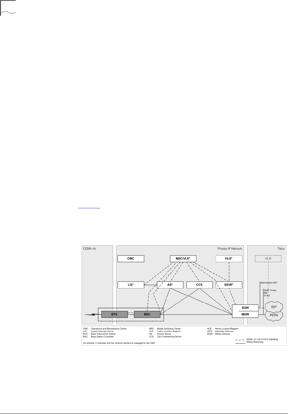
The high-level architecture of the MovingMedia
TM
2000 system is shown in
Figure 1. The Base Station Controller (BSC) and Base Transceiver Station
(BTS) Network Elements are highlighted.
Figure 1
MovingMedia 2000 System Architecture
Core Voice Network Elements
The Network Elements in the Core Network (Voice) are:
n
MovingMedia™ 2000 Mobile Switching Center (MSC)
n
MovingMedia™ 2000 Signaling Server

iCell All IP Radio Access Network Macro Pole Mount BTS Overview
11
Part Number D01309
MovingMedia™
2000
iCell All IP Radio Access Network Macro Pole Mount BTS
July 2007
Installation and Initial Configuration Guide
n
MovingMedia™ 2000 Access Server (MRF)
n
MovingMedia™ 2000 Call Conferencing Server
n
MovingMedia™ 2000 Lawful Intercept Server
n
MovingMedia™ 2000 Home Location Register (HLR) Server
n
MovingMedia™ 2000 Intelligent Media Gateway (IMG)
n
MovingMedia™ 2000 Operation and Maintenance Center (OMC)
Core Data Network Elements
The Network Elements in the Core Network (Data) are:
n
Total Control 800 Packet Data Serving Node (PDSN)
n
Total Control 1000 Packet Data Serving Node (PDSN)
n
Total Control 2000 Packet Data Serving Node (PDSN)
n
Total Control Home Agent TC3100 (HA)
n
Common Element Manager (CEM)
IP Radio Access Network Elements
n
iCell Pico Base Transceiver Station
n
iCell Macro Indoor Base Station Subsystem
n
ICell Macro Pole Mount Base Transceiver Station
Base Station Subsystem
A BSC and the associated BTS are known collectively as a Base Station
Subsystem (BSS).
Base Station Controller
The BSC manages call control and interconnections to the other network
elements.
The BSC application is supported by an operating system that also provides
platform services. While the BSC has several physical platforms, each physical
platform runs the same BSC application and platform services.
The Macro Pole Mount BTS communicates with the BSC over an Ethernet (IP)
connection. Soft BSC servers can be centralized at any convenient location.
This guide does not describe all BSC configurations, which vary based on
network and operator requirements.

12
About This Guide
iCell All IP Radio Access Network Macro Pole Mount BTS
Part Number D01309
Installation and Initial Configuration Guide
July 2007
Macro Pole Mount BTS
The Macro Pole Mount BTS provides radio frequency (RF) connectivity for the
BSC. The Macro Pole Mount BTS implements full BTS functionality, according
to CDMA 2000 standards, plus some additional supporting components, such
as the Ethernet controller, and GPS receiver with antenna.
Figure 2
External View of Macro Pole Mount BTS
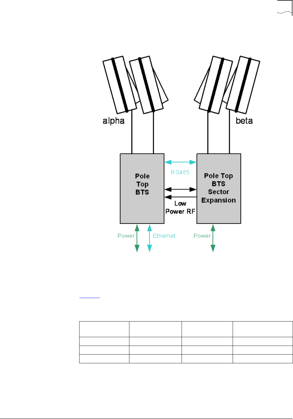
A single Macro Pole Mount BTS supports 1FA/1S configuration and will provide
20 Watt output power. Also, additional sectors support can be provided by using
Macro Pole Mount BTS sector expansion components. Multi-sector
configuration is shown in Figure 3.
iCell All IP Radio Access Network Macro Pole Mount BTS Overview
13
Part Number D01309
MovingMedia™
2000
iCell All IP Radio Access Network Macro Pole Mount BTS
July 2007
Installation and Initial Configuration Guide
Figure 3
Macro Pole Mount BTS Multi-sector Configuration
Table 1 Shows the basic Macro Pole Mount BTS configuration.
The Macro Pole Mount BTS is designed to support the following mounting
options:
n
Pole-mounted
n
Top, middle, or bottom
Table 1
Basic Macro Pole Mount BTS Configurations
FA Sector Macro Pole Mount
BTS Macro Pole Mount BTS
Sector Expansion (
1 1 1 N/A
1 2 N/A 1
1 3 N/A 2

14
About This Guide
iCell All IP Radio Access Network Macro Pole Mount BTS
Part Number D01309
Installation and Initial Configuration Guide
July 2007
n
Wall-mounted (indoor or outdoor).
The Macro Pole Mount BTS is equipped with lightning protection and designed
to operate in a tough outdoor environment (refer to Chapter 3 for details).
Order of Tasks
This Macro Pole Mount BTS Installation and Initial Configuration Guide
describes all of the tasks required to install and configure a Macro Pole Mount
BTS. This guide has 4 main sections:
n
Pre-Installation
n
Installation
n
Initial Configuration
n
Installation Verification.
Follow the tasks in the order that they are presented to successfully install and
configure the Macro Pole Mount BTS.
Pre-Installation Task Outline
Pre-installation tasks are tasks that can and should be done before the Macro
Pole Mount BTS arrives on site.
Installation Task Outline
Installation tasks are tasks that are done after all pre-installation tasks are
completed and the Macro Pole Mount BTS is onsite.
Initial Configuration Task Outline
Initial configuration tasks are tasks that are done after all installation tasks are
completed.
Installation Verification Task Outline
Installation verification tasks are tasks that are done after all initial configuration
tasks are completed.
Conventions
15
Part Number D01309
MovingMedia™
2000
iCell All IP Radio Access Network Macro Pole Mount BTS
July 2007
Installation and Initial Configuration Guide
Conventions
This guide may contain notices, figures, screen captures, and certain text
conventions.
Notices
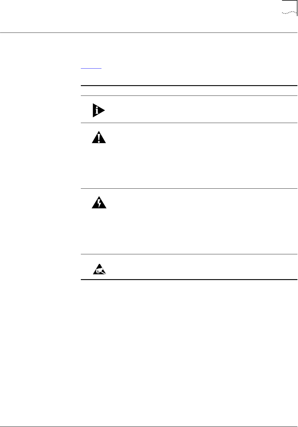
Table 2 lists notice icons used in this guide.
Table 2
Notice Icon Descriptions
Icon Notice Type Description
Information Note Information that contains important features or
instructions but is not hazard-related.
Caution or Warning Cautions are preceded with the word
Caution
. This
type of caution indicates a potentially hazardous
situation which, if not avoided, may result in minor or
moderate injury. It may also alert against unsafe
practices and potential program, data, system, or
device damage.
Warnings are preceded with the word
Warning
. This
type of warning indicates a potentially hazardous
situation which, if not avoided, could result in death or
serious injury.
Caution or Warning
due to potential
electrical hazard
Cautions due to potential electrical hazards are
preceded with the word
Caution
. This type of caution
indicates a potential electrical hazard. This hazard, if
not avoided, may result in minor or moderate injury. It
may also alert against unsafe practices and potential
program, data, system, or device damage.
Warnings due to potential electrical hazards are
preceded with the word
Warning
. This type of warning
indicates a potential electrical hazard. This hazard, if
not avoided, could result in death or serious injury.
ESD Information that indicates proper grounding precautions
are required before handling a product.

16
About This Guide
iCell All IP Radio Access Network Macro Pole Mount BTS
Part Number D01309
Installation and Initial Configuration Guide
July 2007
Figures and Screen
Captures
This guide provides figures and screen captures as examples. These examples
contain sample data. This data may vary from the actual data on an installed
system.
Text
Table 3 lists text conventions in this guide.
Table 3
Text Convention Descriptions
Convention Description
Text represented as a
screen
display
This typeface
represents text that appears on a terminal
screen, for example
login:
.
Text represented as
user
entry
.
This typeface
represents commands entered by the
user, for example,
cd $HOME
.
Text represented as
menu
,
sub-menu
,
tab
, and
field
names
This typeface
represents all menu, sub-menu, tab, and field
names within procedures, for example:
On the
File
menu, click
New
.
Text represented by <variable>This typeface represents a required variable, for example:
<filename>
Related Documentation
17
Part Number D01309
MovingMedia™
2000
iCell All IP Radio Access Network Macro Pole Mount BTS
July 2007
Installation and Initial Configuration Guide
Related
Documentation
The Macro Pole Mount BTS products are part of the MovingMedia
TM
2000
product line for CDMA2000©. The Macro Pole Mount BTS documentation is part
of the documentation for the entire MovingMedia
TM
2000 product line.
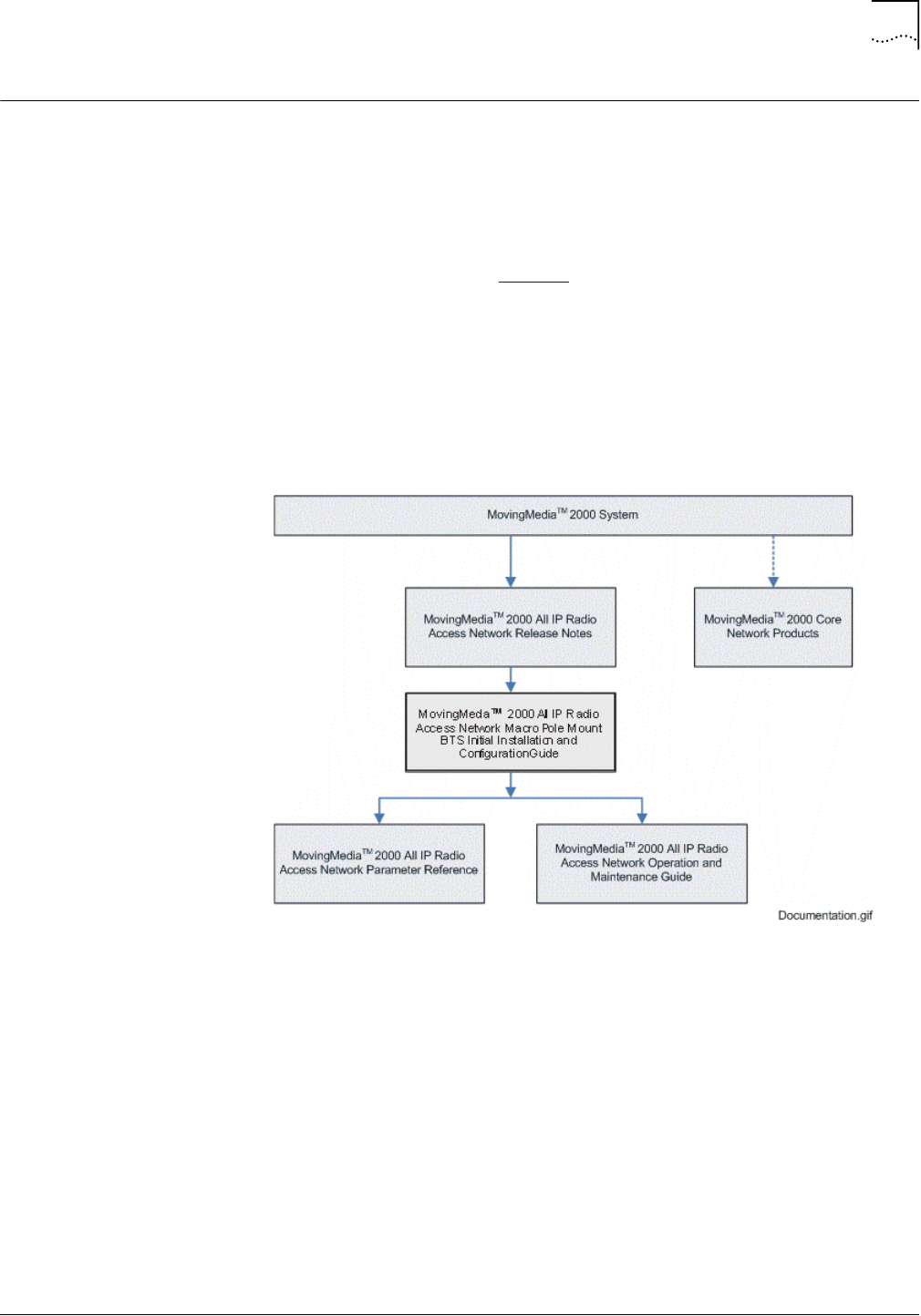
The relationship of the Macro Pole Mount BTS documentation to other
MovingMedia
TM
2000 documentation is displayed in the Macro Pole Mount BTS
document roadmap shown in Figure 4.
These documents contain additional information about the MovingMedia
TM
2000
system in general, and in particular, how to install, provision, operate, and
maintain the Macro Pole Mount BTS.
Figure 4
Document Roadmap
Access Network Documentation
The following documents contain information on how to install, operate, and
maintain the Macro Pole Mount BTS.
n
MovingMedia 2000
TM
iCell All IP Radio Access Network Release Notes
n
iCell All IP Radio Access Network Macro Pole Mount BTS Installation and
Initial Configuration Guide
n
MovingMedia 2000
TM
iCell All IP Radio Access Network Operation and
Maintenance Guide
n
iCell BSS Parameter Configuration Reference.

18
About This Guide
iCell All IP Radio Access Network Macro Pole Mount BTS
Part Number D01309
Installation and Initial Configuration Guide
July 2007
Core Network Documentation
The following documents contain additional information about the
MovingMedia
TM
2000 system in general, and in particular, how to install,
provision, operate, and maintain Network Elements in the Core Network.
n
MovingMedia™ 2000 System Overview
n
MovingMedia™ 2000 Core Network Release Notes
n
MovingMedia™ 2000 Mobile Switching Center Server Provisioning Guide
n
MovingMedia™ 2000 Mobile Switching Center Server Operations and
Maintenance Guide
n
MovingMedia™ 2000 Home Location Register and Authentication Center
Guide
n
MovingMedia™ 2000 Signaling Server Application Guide
n
MovingMedia™ 2000 Access Server (MRF) Guide
n
MovingMedia™ 2000 Lawful Intercept Server Guide
n
MovingMedia™ 2000 Call Conference Server Guide
n
MovingMedia™ 2000 Operations and Maintenance Center Interface Guide
n
MovingMedia™ 2000 cPCI System Guide
n
MovingMedia™ 2000 Intelligent Media Gateway documentation set.
Contacting Customer
Service
For information about customer service, including support, training, code
releases and updates, contracts, and documentation, visit our websites at
http://support.utstar.com.cn
(China Service Center) and
http://support.utstar.com
(other Service Centers).
Before contacting technical support, have this information available:
n
Contract number
n
Product information
n
Software and hardware versions
n
Serial numbers
n
Problem description
n
Symptoms
n
Known causes
n
Trouble locating and clearing attempts.
Obtaining Technical
Assistance
UTStarcom maintains a strong global presence, operating Technical Response
and Service Centers, in the US, Japan, India, China, Ireland, Mexico and Brazil.
These centers are available for technical telephone support to entitled
customers during normal business hours. After hours support is available to
customers who purchase a premium Service Agreement.

Contacting Customer Service
19
Part Number D01309
MovingMedia™
2000
iCell All IP Radio Access Network Macro Pole Mount BTS
July 2007
Installation and Initial Configuration Guide
Support Website
The UTStarcom Support website provides a variety of tools to assist customers
in resolving technical issues on UTStarcom products. The UTStarcom Support
website is available 24 hours per day. Customer registration is required. Certain
premium features require a valid Service Agreement.

20
About This Guide
iCell All IP Radio Access Network Macro Pole Mount BTS
Part Number D01309
Installation and Initial Configuration Guide
July 2007
Warranty Support
UTStarcom provides its customers warranty support per the terms of the
UTStarcom Warranty Statement for their equipment. Customers who require
warranty support should contact the UTStarcom Service Center that serves their
territory.
Contact details for the China Service Center can be found at
http://support.utstar.com.cn
Contact details for all other Service Centers can be found at
http://support.utstar.com
Contacting Technical
Documentation
To provide comments on this documentation, send an e-mail to:
techdoc.feedback@utstar.com
Please include the name and part number of the guide being referenced. If
applicable, provide the chapter and page number.


Part Number D01309
MovingMedia™ 2000 iCell All IP Radio Access Network Macro Pole Mount BTS
July 2007
Installation and Initial Configuration Guide
1
P
REREQUISITES
About This Chapter
This chapter describes the prerequisites required to install the Macro Pole
Mount BTS.
This chapter includes:
■
Installer Requirements
■
Hardware Requirements
■
Software Requirements
■
Network Planning Requirements
Installer Requirements
This section describes the installer personnel requirements. These include:
■
Skills and Knowledge
■
Supporting Documentation
Skills and Knowledge
The installer of a Macro Pole Mount BTS should have general
telecommunications and electrical circuit knowledge.
Supporting
Documentation
This document provides all the necessary information to install, configure,
integrate, and test a Macro Pole Mount BTS. No other documents are required.
The customer-specific network planning document (engineering specifications
for the site and network) and the MM2000 iCell All IP Radio Access Network
Parameter Reference Guide are required for configuration of CDMA2000©
parameters after installation and initial configuration. The network planning
document also provides the information necessary to complete the Network
Planning Requirements.
The documents in the Macro Pole Mount BTS documentation set are listed in
Related Documentation on page 17.
Hardware
Requirements
This section outlines the hardware required to install the Macro Pole Mount
BTS. The hardware includes:
■
Laptop
■
Mobile Phones

24
Chapter 1: Prerequisites
MovingMedia™ 2000 iCell All IP Radio Access Network Macro Pole Mount BTS
Part Number D01309
Installation and Initial Configuration Guide
July 2007
■
Miscellaneous Hand Tools
■
Cables
■
Recommended Test Equipment
Laptop
A laptop PC is required for the installation, configuration, verification, and
network integration of the Macro Pole Mount BTS. The recommended
requirements for the laptop are listed in Table 4.
Mobile Phones
Two mobile phones are required for making loopback test calls in the Loopback
Testing on page 96. A loopback test was performed prior to on-site delivery of
the Macro Pole Mount BTS using factory settings. Table 5 lists the mobile
models used for factory loopback testing.
Other mobiles may be used for making loopback test calls.
Ensure that a suitable USB data cable is available for the mobile used in making
loopback test calls.
Miscellaneous Hand
Tools
The miscellaneous hand tools required for the installation of a Macro Pole
Mount BTS are listed in Table 6.
Table 4
Test Client Requirements
Component Minimum Recommended
Operating System Microsoft® Windows® XP
Professional Edition Microsoft® Windows® XP
Professional Edition
CD ROM Drive 24X 48X
Serial Port 1 1
USB Port 1 1
Ethernet Port and Card 10/100 10/100
Table 5
Supported Test Mobiles
Vendor Model
UTStarcom Audiovox 8900 (CDMA2000
©
)
Kyocera
Table 6
Tools Required for Installation
Tool Phase
No 2 Phillips Screwdriver Installation
Flat head screw driver Installation
Wrench for Type N connectors Installation
3/4inch wrench Installation

Hardware Requirements
25
Part Number D01309
MovingMedia™ 2000 iCell All IP Radio Access Network Macro Pole Mount BTS
July 2007
Installation and Initial Configuration Guide
Cables
Several cables and antennae are required throughout the installation,
configuration, and verification process. Table 7 lists the cables required for the
Macro Pole Mount BTS installation, configuration, and verification process.
Recommended Test
Equipment
Two mobile phones are required for making test calls to verify Core Network
integration. A voice test call and a data test call (if applicable) are made to verify
the integration. The mobiles must have a subscriber profile in the HLR for voice
calls and the AAA for data calls in order for the test calls to succeed.
The Operator (NOC personnel) should provision the test mobiles in the
respective HLR and/or PDSN before test calls need to be made. This guide
does not describe how to provision a subscriber in the HLR or the AAA server.
10 mm socket wrench Installation
32mm open end wrench Installation
Metal cutting hack saw Installation
10 inch water pump pliers Installation
Break Out Box Required for on-site debug process (May be
purchased separately)
Table 6
Tools Required for Installation
Tool Phase
Table 7
Required Cables and Antennae
Cable Description
Cellular Sector Antennae Main and Diversity sector antenna (20 Watt output)
Power Cable Refer to Installation section for details
Ethernet Cable CAT-5 Ethernet cable with 2 RJ-45 connector ends.
Console Serial Cable Standard serial cable with 1 male DB-9 connector end and 1
female DB-9 connector end.
Break Out Box Data Cable
(When Break Out Box used) CAT-5 Ethernet cable with 2 RJ-45 connector ends. One for
each sector expansion unit and one for Break Out Box. Refer
to Figure 15.
RF Cables Corrugated cables with N-type (male) connectors to connect
sectors expansion BTS and external GPS antennae (if
required).
Antenna cable Corrugated RF cable with DIN 7/16 plug (male) connector.
(50 ohm impedance, 3GHz minimum interface frequency and
rated for minimum 50 Watt at 2GHz)
Grounding Cables Refer to Macro Pole Mount BTS Grounding Requirements

26
Chapter 1: Prerequisites
MovingMedia™ 2000 iCell All IP Radio Access Network Macro Pole Mount BTS
Part Number D01309
Installation and Initial Configuration Guide
July 2007
Additional recommended test equipment is listed in Table 8. The operator can
use any other equipment that has the same capabilities as the recommended
equipment.
Software
Requirements
The following software is recommended for installing the Macro Pole Mount
BTS:
■
Web browser:
■
Microsoft Internet Explorer version 6.0 or later
■
Firefox web browser version 2.0 or later - alternative web browser for
accessing BSC/BTS configuration. It is also useful for capturing BSC/BTS
logging.
■
Text editor for viewing log and configuration files:
■
Wordpad is recommended for Microsoft Windows.
■
Console software for console emulation and capturing logs into text files.
■
PuTTY (version 0.52 or later) is a versatile freeware console program
available from:
http://www.chiark.greenend.org.uk/~sgtatham/putty/download.html
■
Phone and network deployment diagnostics:
■
Use Qualcomm CAIT or Spirent UDM
■
Contact UTStarcom (refer to Contacting Customer Service) for acquisition
of this software.
Table 8
Recommended Test Equipment
Test Equipment Description
Agilent E7495B All-in-one wireless base station field testing box. Power
meter and CDMA demodulation options required.
Power Meter Used for measuring BTS/PA output power. The meter should
be equipped with multiple slugs to be able to measure output
power at various points in the BTS.
The Bird THRULINE meter is recommended. Refer to
http://www.bird-electronic.com/
Multimeter Refer to http://www.fluke.com/ for a recommended
multimeter.
100W Type N 40dB attenuator Used for connecting the high power signal to the test
equipment. Required for MCPA calibration.
Laptop For Configuration and monitoring
RF Cables To connect test equipment. (Same requirements as for RF
Cables or Antenna cables from Table 7)
Two mobile phones For test calls (Refer to Mobile Phones)

Network Planning Requirements
27
Part Number D01309
MovingMedia™ 2000 iCell All IP Radio Access Network Macro Pole Mount BTS
July 2007
Installation and Initial Configuration Guide
The test client should have all of the software installed as part of the minimum
test client requirements (refer to Table 4 on page 24).
Tools CD ROM
A tools CD ROM may be available that contains the software tools necessary to
install, configure, and test the Macro Pole Mount BTS. Table 9 lists the potential
contents of the tools CD ROM.
USB Drivers
The Loopback Testing phase requires a USB connection. Ensure that the test
client has USB 2.0 drivers installed. Microsoft has USB 2.0 drivers available for
Windows XP.
To check for a USB controller and 2.0 driver in Microsoft Windows XP:
1
Navigate to the Start menu and select
Control Panel > Administrative Tools >
Computer Management
The Computer Management window is displayed.
2
Double-click
System Tools
.
3
Double-click
Device Manager
from the list of tools.
4
Double-click
Universal Serial Bus controllers
.
A list of available USB controllers is displayed.
5
Select a USB controller from the list to view details on the controller and driver.
Drivers can also be updated from this window.
Network Planning
Requirements
This section describes the network planning that must be performed prior to
installing the Macro Pole Mount BTS. This includes:
■
Existing Core IP Network Requirements
■
IP Address Assignment
■
Hostname Assignment
■
Password and Username Assignment
■
BTS Site Information
Table 9
Tools CD ROM Contents
Software
Audiovox Phone Set
Kyocera Phone Set
SSH Telnet Client
PuTTY
Trimble Thunderbolt Monitor
Qualcomm CAIT or Spirent UDM

28
Chapter 1: Prerequisites
MovingMedia™ 2000 iCell All IP Radio Access Network Macro Pole Mount BTS
Part Number D01309
Installation and Initial Configuration Guide
July 2007
Existing Core IP
Network Requirements
The Macro Pole Mount BTS implements the Access Network part of a
CDMA2000© system. The Access Network is integrated with an existing
CDMA2000© Core Network. The Core Network and a private IP network must
already be set up before the Access Network can be integrated with the Core
Network (MSC and PDSN).
IP Address Assignment
The following IP addresses must be set up prior to installing the BTS:
■
Test Client IP Addresses
■
Access Network IP Addresses
■
Core Network IP Addresses
Test Client IP Addresses
The test client is used to connect to the Network Elements, and must be on the
same subnet. The required IP addressing information for the test client is listed
in Table 10.
Access Network IP Addresses
The following tables list the IP addressing information required for the Access
Network.
Table 10
Required IP Addressing for Test Client
Test Client
IP address 1
Subnet mask 1
Default gateway 1
IP address 2
Subnet mask 2
Default gateway 2
Table 11
Required IP Addressing for Ethernet Switch
Ethernet Switch
Switch IP Address
Subnet Mask
Default Gateway
Table 12
Required IP Addressing for BSC
BSC
BSC IP Address

Network Planning Requirements
29
Part Number D01309
MovingMedia™ 2000 iCell All IP Radio Access Network Macro Pole Mount BTS
July 2007
Installation and Initial Configuration Guide
Core Network IP Addresses
The following table list the IP addressing information required for Core Network
integration (MSC/VLR and PDSN/HA).
Hostname Assignment
Hostnames are optional but useful. Acquire the hostnames for the Macro Pole
Mount BTS components if they are required for the configuration.
Password and
Username Assignment
The Macro Pole Mount BTS components have default usernames and
passwords configured. The BTS components can be assigned new site-specific
usernames and passwords during installation and configuration, or new
usernames and passwords can be configured later by the operator.
Table 14 lists the BSS components that require a username and password to
connect. Have the site-specific usernames and passwords ready before
installation begins so that login information can be changed to site-specific
values.
Passwords must be changed. Site-specific values are required.
The usernames and passwords for the Core Network Elements (MSC, PDSN)
are not set here, but must be available for connection during Core Network
Integration.
BTS Site Information
Some BTS site information is required if the BTS will be loaded with a
configured GPS receiver. It is possible to load the BTS with a GPS receiver that
has not yet been configured.
The GPS receiver uses GPS satellites. If the GPS receiver does not have the
approximate or accurate BTS position (latitude and longitude) then it could take
Table 13
Required IP Addressing for Core Network
Core Network
MSC IP Address
PDSN IP Address
Table 14
Login Configuration for Site
BSS Component Default Username Default Password
Ethernet Switch en
tel os
BSC
icell icell
BSC
root
tel os
BTS
icell icell
BTS root tel os
MSC
msc ms c

30
Chapter 1: Prerequisites
MovingMedia™ 2000 iCell All IP Radio Access Network Macro Pole Mount BTS
Part Number D01309
Installation and Initial Configuration Guide
July 2007
several hours for the GPS receiver to lock onto the appropriate GPS satellites
(there are 24 GPS satellites in operation).
Latitude is given in decimal degrees (+N, -S) and longitude in decimal degrees
(+E, -W). For example, Vancouver, British Columbia, Canada has the following
coordinates:
Latitude: 49.242604 N (deg min sec), Longitude: 123.099414 W (deg min sec).

Part Number D01309
MovingMedia™ 2000 iCell All IP Radio Access Network Macro Pole Mount BTS
July 2007
Installation and Initial Configuration Guide
2
S
ITE
P
REPARATION
About This Chapter
This chapter describes how to prepare a site for the installation of the Macro
Pole Mount BTS.
This chapter includes:
■
Site Planning
■
Site Requirements
Site Planning
Site planning includes planning for:
■
Required Personnel
■
Required Documentation
■
Site Planning Checklist
Required Personnel
The Macro Pole Mount BTS has specific structural, electrical, and
telecommunications requirements. When selecting and preparing a site, specific
personnel and documents must be available as resources for performing the
procedures. The following sections describe these requirements.
Required
Documentation
When preparing a site for installation of a Macro Pole Mount BTS, obtain this
site-specific information:
■
General site information
■
Floor plans
Table 15
Personnel Requirements
Title Job Description Responsibilities
Installer This person performs or oversees
the physical installation of the
equipment and ensures the
installation procedures are
properly followed.
Responsible for assuring the
appropriate personnel and
equipment are available and precise
measurements and careful
inspections are performed.
Site Manager/Facility
Representative This person should be familiar
with the office facilities and know
the engineering, telephone
company, and network contacts.
Responsible for the physical site
where the equipment is to be
installed.
Technician This person maintains the
equipment once it is assembled
and operational.
Responsible for performing the
electrical and network connections.

34
Chapter 2: Site Preparation
MovingMedia™ 2000 iCell All IP Radio Access Network Macro Pole Mount BTS
Part Number D01309
Installation and Initial Configuration Guide
July 2007
■
Power information (grounding and power-level data)
■
Environmental document (heat, humidity tests)
■
Site wiring lists
■
Fire system data
■
Security alarm system data
Site Planning Checklist
The following checklist is provided to assist in the site planning procedure. After
completing the required steps, check them off, or refer back to this list, to ensure
all site planning requirements are met:
■
Reviewing Personnel Requirements
■
Gathering Related Documentation
■
Verifying Power
■
Verifying the Grounding
■
Verifying Fire Protection
■
Verifying Alarms
■
Verifying Site Conditions
■
Verifying Temperature Control
■
Reviewing Standard Macro Pole Mount BTS Location Specifications
■
Reviewing Macro Pole Mount BTS Mounting Guidelines
■
Preparing the Site for the Macro Pole Mount BTS.
Site Plans and Floor
Plans
Generate a site plan and floor plan for equipment layout. The Macro Pole Mount
BTS should be installed according to the clearances outlined in Space
Requirements on page 40.
Site Requirements
This section includes:
■
DC Power Requirements
■
AC Power Requirements
■
Site External Grounding Requirements
■
Macro Pole Mount BTS Grounding Requirements
■
Macro Pole Mount BTS Antenna Grounding
■
GPS Receiver Protection
■
Other Cable Grounding
■
Macro Pole Mount BTS Mounting Options
■
Space Requirements
■
Inspecting and Verifying Site Requirements

Site Requirements
35
Part Number D01309
MovingMedia™ 2000 iCell All IP Radio Access Network Macro Pole Mount BTS
July 2007
Installation and Initial Configuration Guide
DC Power Requirements
Applicable to DC version of Macro Pole Mount BTS only.
The Macro Pole Mount BTS can accept voltages within -36 to -72 VDC range
and typically will be -48 VDC.
Each single Macro Pole Mount BTS or sector expander must be cabled with at
least 500W capable DC power source and no smaller than 8 AWG armored
power cable ready for connection to the Macro Pole Mount BTS.
To maintain the IP67 rating of the product, the power cable attached to the unit
must provide a waterproof connection to the lightning protection unit (LPU).
The fitting supplied with the Macro Pole Mount BTS accepts a cable diameter in
the range of 22 to 27 mm (0.880 to 1.065"). The cable must also be
appropriately temperature rated. Acceptable cables include the following:
■
TECK 90 XLPE 6 AWG/2 (-40C)
http://www.nexans.ca/
http://www.nexans.ca/egy/equip/teck90/1000v2c.html
AC Power Requirements
.
Applicable to AC version of Macro Pole Mount BTS only.
The Macro Pole Mount BTS can accept voltages within 90 to 260 VAC (50/60
Hz) range.
Each single Macro Pole Mount BTS or sector expander must be cabled with at
least a 500W capable AC power source. and no smaller than 10 AWG armored
cable, ready for connection to the Macro Pole Mount BTS.
To maintain the IP67 rating of the product, the power cable attached to the unit
must provide a waterproof connection to the LPU.
The fitting supplied with the Macro Pole Mount BTS accepts a cable diameter in
the range of 22 to 27 mm (0.880 to 1.065"). The cable must also be
appropriately temperature rated. For reference, The fitting supplied with the
Macro Pole Mount BTS accepts the following cable:
■
TECK 90 XLPE 6 AWG/2 (-40C)
http://www.nexans.ca/

36
Chapter 2: Site Preparation
MovingMedia™ 2000 iCell All IP Radio Access Network Macro Pole Mount BTS
Part Number D01309
Installation and Initial Configuration Guide
July 2007
Site External Grounding
Requirements
External grounding requirements include:
■
Site Grounding Responsibility
■
Ground Rods
■
AC Power Grounding
■
Ground Testing
Site Grounding Responsibility
Grounding of the site is the responsibility of the customer. All grounding and
power connections should be made according to local standards.
Ground Rods
Several factors affect external grounding. The major factor is the resistance of
ground rods, which is directly related to soil resistivity in the immediate vicinity of
the rod. The resistivity of the soil determines how many rods are needed and
their dimensions.
Ground rods must be buried at the base of the structure, and at the AC service
entrance and transmission line entry port. The rods must be composed of
copper-clad, high-strength steel with minimum dimensions of 16 mm x 3.1 m
(5/8 in. x 10 ft.).
The rods must be located at least 61 cm (2 ft.) from the edge of the foundation,
and driven deeply enough that the top of the rod is below the frost line of the
installation site.
AC Power Grounding
The AC power ground conductor must be bonded to the ground rod located at
the service entrance. Ground lugs provided in all service entrance equipment
must be bonded to the service ground conductor. The system ground and
neutral must be bonded at one location only, as close as is practical to the
service entrance. All service grounding must conform to the appropriate
electrical codes.
Ground Testing
The external ground systems must be tested separately after installation, and
each resistance to earth ground must be less than 5 ohms. Tests must be
performed twice per year to ensure ground system integrity.
Macro Pole Mount BTS
Grounding
Requirements
Good internal grounding depends on several factors, the most significant of
which is the halo ground. Using a halo ground provides maximum internal
protection for the Macro Pole Mount BTS.
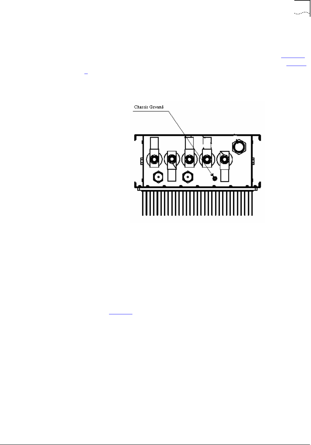
Site Requirements
37
Part Number D01309
MovingMedia™ 2000 iCell All IP Radio Access Network Macro Pole Mount BTS
July 2007
Installation and Initial Configuration Guide
Macro Pole Mount BTS Ground
The Macro Pole Mount BTS and BTS sector expansion are equipped with a
chassis ground connection point at the bottom of the cabinet (refer to Figure 5).
This point should be connected to the top ground bar by #2 AWG wire (Figure
5).
Figure 5
Macro Pole Mount BTS Chassis Ground Connection
.
Figure 6
Example of a Macro Pole Mount BTS Grounding Scheme
Macro Pole Mount BTS
Antenna Grounding
The Macro Pole Mount BTS can be connected to different antenna modules by
rugged coaxial cables. Coaxial cables can create a significant transmission path
during a lightning strike. Grounding cables to multiple points improves lightning
protection on the system, also lowering additive radiation caused by lightning
surge.
Refer to Figure 7 for an example of a Macro Pole Mount BTS grounding
scheme.
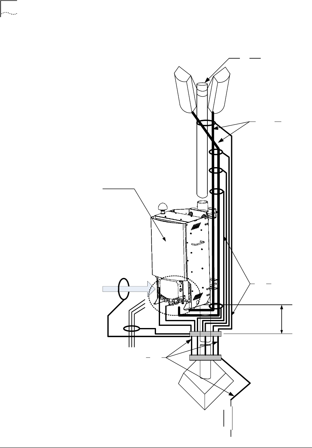
38
Chapter 2: Site Preparation
MovingMedia™ 2000 iCell All IP Radio Access Network Macro Pole Mount BTS
Part Number D01309
Installation and Initial Configuration Guide
July 2007
Figure 7
Example of a Macro Pole Mount BTS Grounding Scheme
Ground
Rods
Top Ground Bar
Bot Ground Bar
#2
AWG
Antenna
cables
Pole
LPU Ground
#2
AWG
DC/AC
Cable
Ethernet
iCell Pole Mount
BTS
8 – 30 cm
Chassis Ground
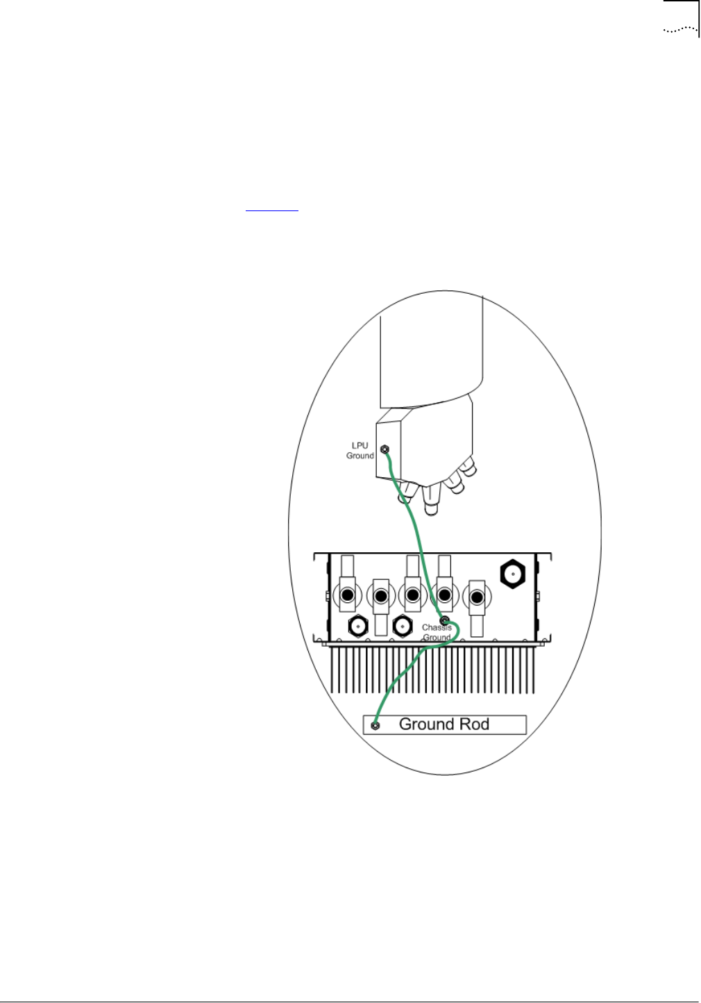
Site Requirements
39
Part Number D01309
MovingMedia™ 2000 iCell All IP Radio Access Network Macro Pole Mount BTS
July 2007
Installation and Initial Configuration Guide
Connect the ground braid directly to the coaxial cable shield braid at multiple
points. Connect all ground wires together at the top grounding bar.
Connect the banding point (between vertical and horizontal cable run) to the top
ground bar with #2 AWG wire, using the minimum possible length of wire.
Refer to Figure 8 for the recommended Macro Pole Mount BTS grounding
connection.
Figure 8
Recommended Macro Pole Mount BTS Grounding Connections
Ensure that the bottom ground bar is connected directly to the site ground ring
using the minimum possible length of #2 AWG wires.
GPS Receiver Protection
The Macro Pole Mount BTS uses a GPS receiver, GPS antenna, and the GPS
satellite system to maintain precise timing.
The Macro Pole Mount BTS case includes a GPS antenna, with a lightning
protector, that is connected to the GPS RF input.

40
Chapter 2: Site Preparation
MovingMedia™ 2000 iCell All IP Radio Access Network Macro Pole Mount BTS
Part Number D01309
Installation and Initial Configuration Guide
July 2007
Warning:
External (customer supplied) antenna can be attached to the GPS antenna
input. In this case, the on-cabinet GPS coaxial cable should be disconnected.
The Macro Pole Mount BTS provides +5 VDC voltage at the GPS antenna input
connector to power the external antenna. For a non-standard GPS antenna,
make sure the voltage is sufficient for normal antenna operation and that the
power consumption of the antenna does not exceed 275mW.
A GPS antenna is an active antenna. Avoid a short circuit termination of the
GPS antenna input on the Macro Pole Mount BTS case. If different voltage is
used to feed an external GPS antenna, use the DC block module with external
lightning protector to avoid back current leakage into the GPS antenna input.
Other Cable Grounding
All other cables such as telephone cables, data cables, and power cables
should be protected by metal conduit with single-point ground connection to the
top ground bar (refer to Figure 6).
The Macro Pole Mount BTS incorporates lightning protection on all incoming
wires. External equipment (such as Ethernet switch, BSC or other) has to be
lightning protected.
Cables between any two structures must be shielded and employ a messenger
cable. The messenger cable must be bonded to the respective building ground
at each corner. The shields must be bonded to the building ground at each
corner.
Macro Pole Mount BTS
Mounting Options
The Macro Pole Mount BTS comes with different installation kits.
Pole Mounting
The Macro Pole Mount BTS can be installed on steel, concrete, or wood poles
with diameter from 12 to 30 cm (5 to 12 inches).
Refer to Chapter 3, Macro Pole Mount BTS Installation and Power Cabling, for
the details.
Wall Mounting
The Macro Pole Mount BTS can be installed on wood, concrete, masonry,
grout-filled-block, and hollow-block walls.
Refer to Chapter 3, Macro Pole Mount BTS Installation and Power Cabling, for
the details.
Space Requirements
The Macro Pole Mount BTS requires both vertical clearance and area
clearance.

Site Requirements
41
Part Number D01309
MovingMedia™ 2000 iCell All IP Radio Access Network Macro Pole Mount BTS
July 2007
Installation and Initial Configuration Guide
Vertical Clearance
The Macro Pole Mount BTS requires a minimum clearance for cable
connections at the bottom of the cabinet (LPU module).
The bottom of the LPU should be a minimum of 23cm (9 inch) above the top of
any surface. The ½” Superflex jumper antenna cable has a turn radius of
1.25" / 32 mm and requires at least 9" / 230 mm for the bend.
Other antennae cables may have a larger turn radius requiring more vertical
clearance.
The GPS receiver and antennae installed on the top of the Macro Pole Mount
BTS unobstructed upward visibility for satellite acquisition. Do not install any
solid metal constructions above the Macro Pole Mount BTS.
Area Clearance
Installing the Macro Pole Mount BTS requires a minimum clearance behind the
cabinet. Ensure there is 60 cm (2 feet) clearance behind the pole to allow
sufficient access for through-rod installation.(refer to Figure 10).
Proper installation also requires adequate mechanical clearance.
Figure 9 shows the minimum vertical clearances for the Macro Pole Mount BTS.
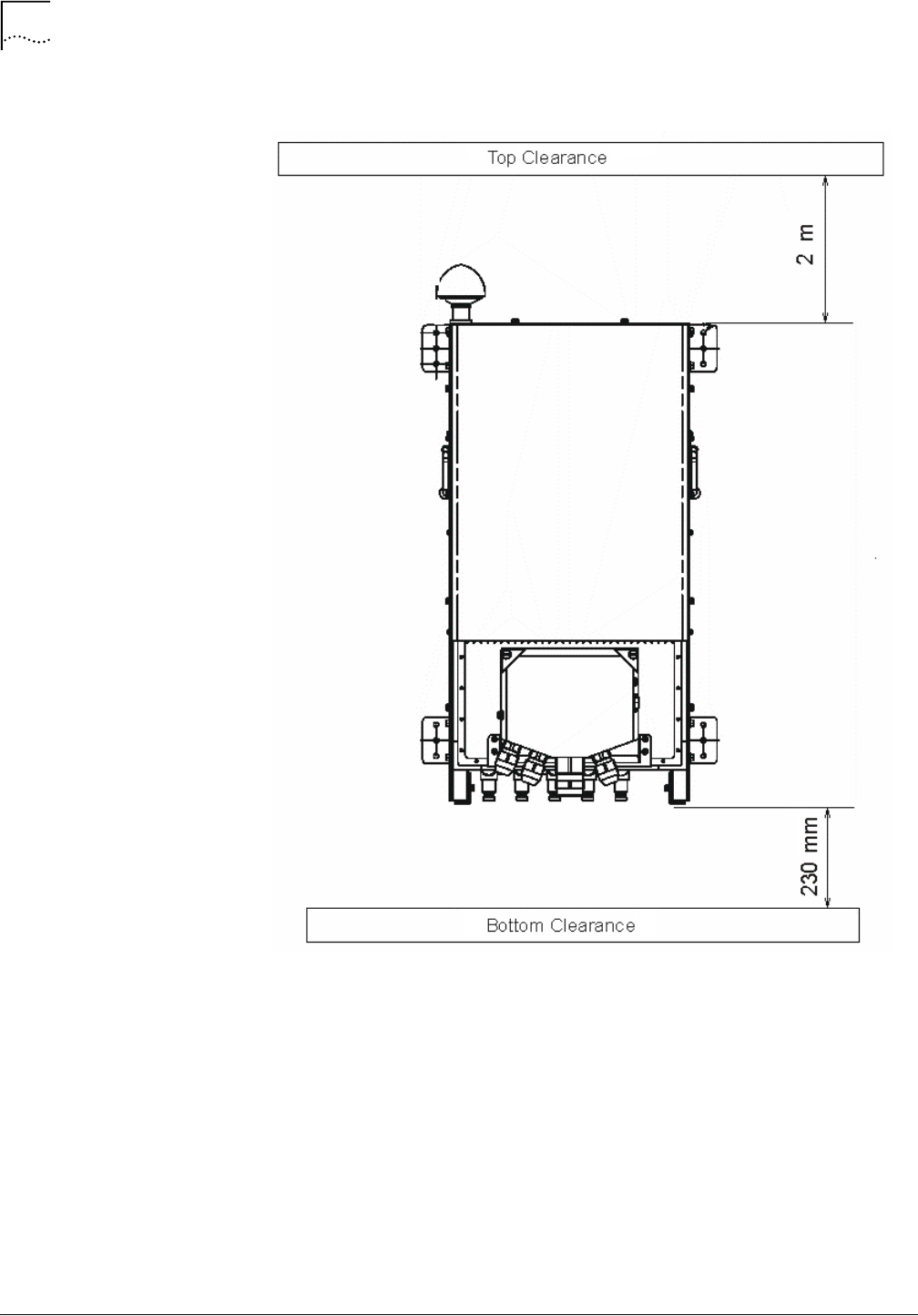
42
Chapter 2: Site Preparation
MovingMedia™ 2000 iCell All IP Radio Access Network Macro Pole Mount BTS
Part Number D01309
Installation and Initial Configuration Guide
July 2007
Figure 9
Minimum Vertical Clearances for the Macro Pole Mount BTS
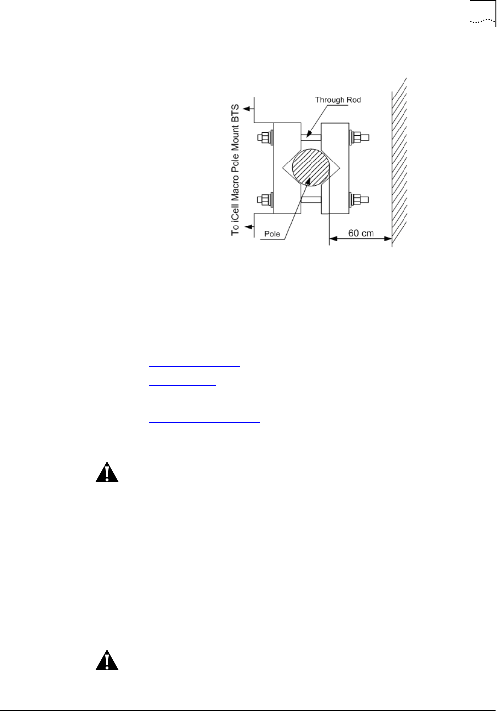
Site Requirements
43
Part Number D01309
MovingMedia™ 2000 iCell All IP Radio Access Network Macro Pole Mount BTS
July 2007
Installation and Initial Configuration Guide
Warning:
Warning:
Figure 10
Installation Clearance for Macro Pole Mount BTS
Inspecting and Verifying
Site Requirements
Inspect the Macro Pole Mount BTS installation site to verify the location meets
the minimum requirements.
This section includes:
■
Verifying Power
■
Verifying Grounding
■
Fire Protection
■
Verifying Alarms
■
Verifying Site Conditions
Verifying Power
Power must be verified by qualified personnel.
To verify power, perform the following steps:
1
Check the external meter to verify that the power capacity is at full building
capacity.
2
Verify the surge protectors are installed.
3
Verify that adequate DC or AC power environments are available. Refer to DC
Power Requirements or AC Power Requirements. If the environment does not
meet power requirements, contact the utility company or site manager.
Verifying Grounding
Grounding must be verified by qualified personnel.

44
Chapter 2: Site Preparation
MovingMedia™ 2000 iCell All IP Radio Access Network Macro Pole Mount BTS
Part Number D01309
Installation and Initial Configuration Guide
July 2007
Warning:
To verify grounding:
1
Verify the internal ground system has a low impedance path to ground to
achieve a minimal potential difference between conductive structures within the
site.
2
Verify the Master Ground Bar (MGB) is properly connected to the external
ground.
3
Inspect the connections between the MGB and the external ground ring.
4
Verify all metallic phone lines (span lines, auto-dialup modem lines, leased span
lines, and any other switched network or leased telephone lines) entering or
leaving the site are equipped with a three-electrode gas tube protector.
5
Verify the ground side of the gas tubes are tied to the MGB.
6
Verify the battery racks are properly grounded to the MGB.
All ground cables should have a bend radius of 8 in (20 cm) or more.
Fire Protection
Install fixed fire suppression equipment. Possible types are:
■
Halon gas system
■
Carbon Dioxide (CO2) system
■
Sprinkler system (UTStarcom recommends using "dry pipe" sprinkler
systems that remove all power to a room before filling the overhead
sprinklers with water.)
In addition to the fixed fire suppression equipment, there should be at least two
5-lb ABC class portable fire extinguishers on the premises before equipment
installation begins.
If there is no fire suppression equipment installed, contact the site manager or
facility representative.
Verifying Alarms
Ensure any alarms are installed per site-specific documentation. These alarms
may include:
■
Vandalism
■
Surface water
■
Intrusion
■
Fire
■
Building temperatures (high and low)
■
Any customer-specific options.
If no alarms are installed, contact the site manager or facility representative.

Site Requirements
45
Part Number D01309
MovingMedia™ 2000 iCell All IP Radio Access Network Macro Pole Mount BTS
July 2007
Installation and Initial Configuration Guide
Warning:
Verifying Site Conditions
The site must be clean and free of obstructions. Verify that:
■
There are no obstructions
■
Any dust and/or water in the area is cleared away.
If site conditions do not comply, contact the site manager or facility
representative.
External cabling must be supported by cable racks not attached to the Macro
Pole Mount BTS. If not independently supported the weight of the cabling may
reduce the ability of the system to withstand Zone 4 Seismic activity.
If the installer is not responsible for correcting noted shortfalls, notify responsible
individuals of any deficiencies and ensure the deficiencies are corrected before
commencing installation.
Installation of ancillary equipment (for example: power supplies, cable racks,
batteries) may be the responsibility of the installer.

46
Chapter 2: Site Preparation
MovingMedia™ 2000 iCell All IP Radio Access Network Macro Pole Mount BTS
Part Number D01309
Installation and Initial Configuration Guide
July 2007

Part Number D01309
MovingMedia™ 2000 iCell All IP Radio Access Network Macro Pole Mount BTS
July 2007
Installation and Initial Configuration Guide
II
I
NSTALLATION
Chapter 3
Macro Pole Mount BTS Installation and Power Cabling
Chapter 5
Transmission, Antenna and GPS Connection Guidelines
Chapter 4
Powering On and Off

Part Number D01309
MovingMedia™ 2000 iCell All IP Radio Access Network Macro Pole Mount BTS
July 2007
Installation and Initial Configuration Guide
3
M
ACRO
P
OLE
M
OUNT
BTS I
NSTALLATION
AND
P
OWER
C
ABLING
About This Chapter
This chapter describes installation power cabling for the Macro Pole Mount BTS.
This chapter includes:
■
Macro Pole Mount BTS Installation
■
Before Connecting Power Cables
■
Cabling Power Supply
Macro Pole Mount
BTS Installation
This section includes:
■
Mounting on a Pole
■
Mounting on a Wall
Mounting on a Pole
Figure 11 shows the outside dimensions of the Macro Pole Mount BTS and the
accessories required for pole mounting installation.
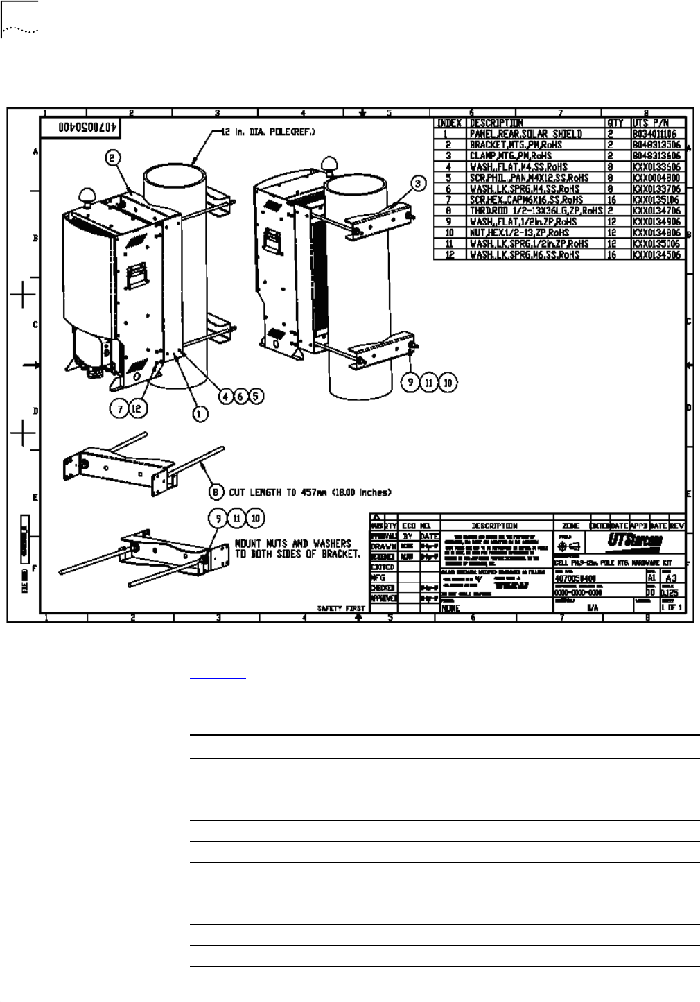
50
Chapter 3: Macro Pole Mount BTS Installation and Power Cabling
MovingMedia™ 2000 iCell All IP Radio Access Network Macro Pole Mount BTS
Part Number D01309
Installation and Initial Configuration Guide
July 2007
Figure 11
Macro Pole Mount BTS Mounting Bracket Dimensions
Table 16 lists complete Macro Pole Mount BTS mounting kit details.
Table 16
Macro Pole Mount BTS Mounting Kit Description
Index Description Quantity
1Panel, Rear, Solar Shield 2
2Bracket 2
3Clamp 2
4Washer, Flat, M4 8
5Screw, Phillips, M4 8
6Washer, Spring, M4 8
7Screw, HEX, CAP M6 16
8Through Rod, ½-13X36 LG 2
9Washer, Flat, ½-inch 12
10 Nut, HEX, ½-13 12
11 Washer, Spring, ½-inch 12
Macro Pole Mount BTS Installation
51
Part Number D01309
MovingMedia™ 2000 iCell All IP Radio Access Network Macro Pole Mount BTS
July 2007
Installation and Initial Configuration Guide
To mount the Macro Pole Mount BTS:
1
Adjust through rods (8) to the required length (Use metal cutting hack saw).
2
Install brackets (2) on Macro Pole Mount BTS cabinet. Use screws (7) and
washers (12) to fasten brackets to the Macro Pole Mount BTS body.
3
Insert four through rods (8) into brackets holes and fasten it by using washer (9),
washer (11) and nut (10).
The bracket (8) has two hole sets for different pole diameters. Use external
holes pair for mounting poles with a diameter from 12 to 15 cm (5 to 6 inch). Use
internal holes pair for mounting poles with a diameter from 15 to 31 cm (6 to 12
inch).
Tightening torque for ½-13 nuts on the threaded rods is subjective. Do not over
tighten nuts. If over tightened the brackets will bend.
4
Attach solar shield panel (1) to the brackets (2) by using washer (4), screw (5)
and washer (6).
5
Lift Macro Pole Mount BTS to the required height.
6
Attach clamps (3) and fasten them by using washer(9), nut (10) and washer
(11).
12 Washer, Spring, M6 16
Table 16
Macro Pole Mount BTS Mounting Kit Description
Index Description Quantity
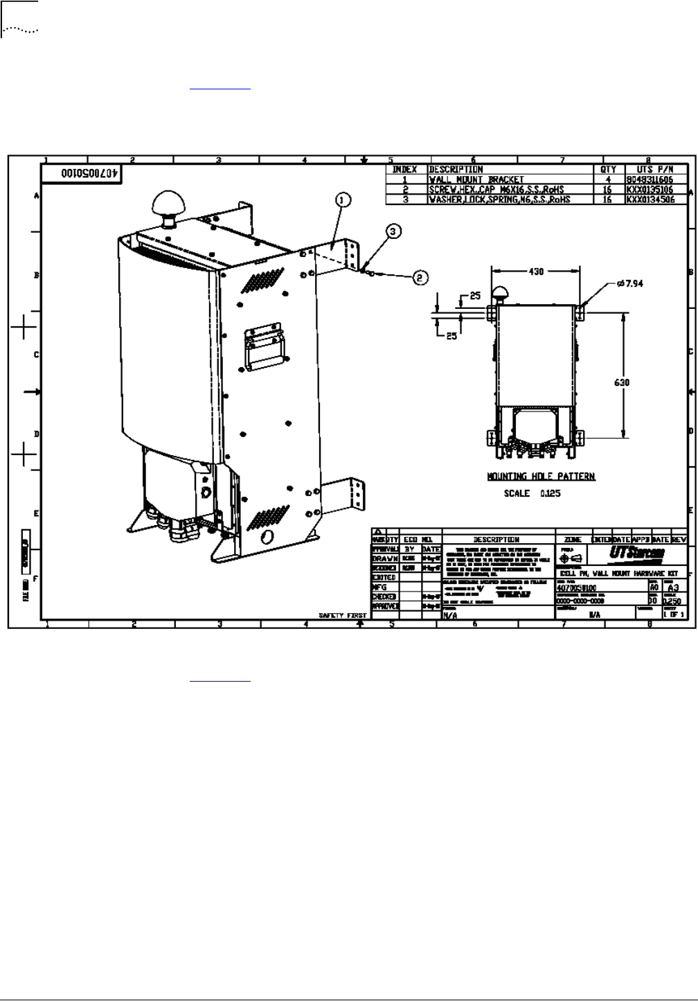
52
Chapter 3: Macro Pole Mount BTS Installation and Power Cabling
MovingMedia™ 2000 iCell All IP Radio Access Network Macro Pole Mount BTS
Part Number D01309
Installation and Initial Configuration Guide
July 2007
Mounting on a Wall
Figure 12 shows the outside dimensions of the Macro Pole Mount BTS and
accessories required for the wall-mounting installation.
Figure 12
BTS Wall Mounting
Figure 13 shows the mounting holes dimensions and location for the
wall-mounting installation. These mounting hole centers apply to mounting on all
wall types.
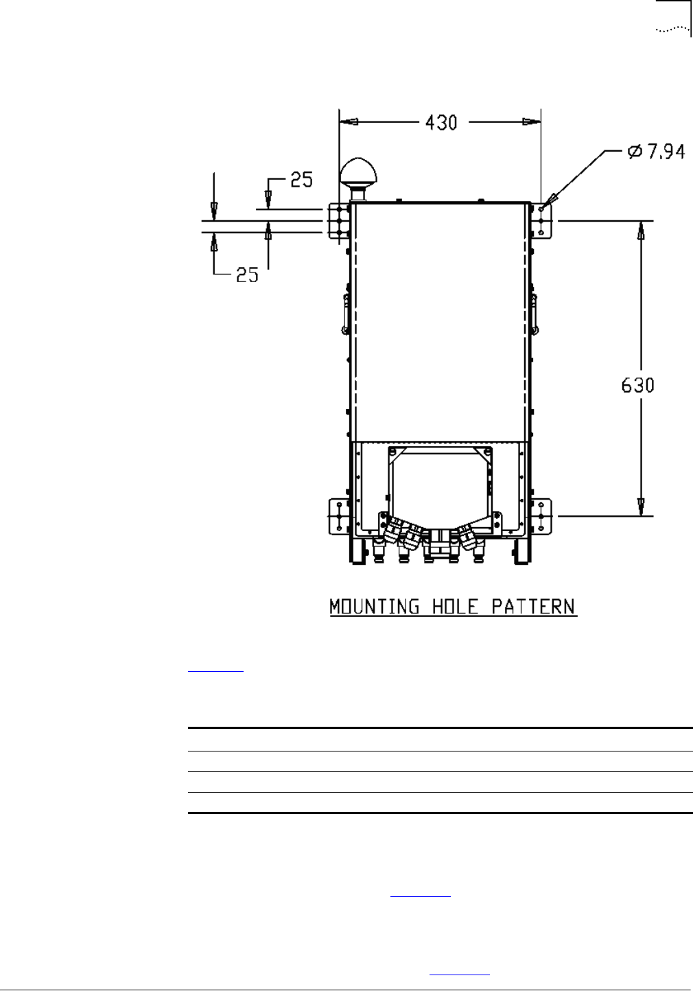
Macro Pole Mount BTS Installation
53
Part Number D01309
MovingMedia™ 2000 iCell All IP Radio Access Network Macro Pole Mount BTS
July 2007
Installation and Initial Configuration Guide
Figure 13
BTS Wall-Mounting Hole Pattern
Table 17 lists BTS wall-mount kit details.
To mount the BTS on a wall:
1
Prepare wall-mounting anchors for BTS wall-mount installation (Use the
mounting hole pattern shown in Figure 13).
a
To mount on a wooden wall use:
■
¼-20 X 1-1/2" stainless steel lag bolts (4)
■
Mounting hole pattern shown in Figure 13.
Table 17
BTS Wall-Mount Kit Description
Index Description Quantity
1Wall mount bracket 2
2Screw, HEX, Cap, M^ 2
3Washer, lock, Spring, M6 2
54
Chapter 3: Macro Pole Mount BTS Installation and Power Cabling
MovingMedia™ 2000 iCell All IP Radio Access Network Macro Pole Mount BTS
Part Number D01309
Installation and Initial Configuration Guide
July 2007
Warning:
Warning:
Warning:
■
7/16 wrench to tighten screws.
b
To mount on concrete, masonry, grout-filled block or hollow block use:
■
Dynabolt sleeve anchors- hex head carbon steel zinc plating
■
Mounting hole pattern shown in Figure 13
■
Red Head p/n BLXHN1614.
2
Install brackets (1) on Macro Pole Mount BTS cabinet.
3
Use screw (2) and washer (3) to fasten brackets to Macro Pole Mount BTS
body.
4
Lift Macro Pole Mount BTS to the required height
5
Fasten the screws to wall anchors.
Macro Pole Mount
BTS Power Cabling
Before Connecting Power Cables
Verify Macro Pole Mount BTS power supply version prior to wiring power cords.
Power connections to the Macro Pole Mount BTS must comply with local safety
codes.
Power connections must be performed by qualified personnel only.
Verifying DC/AC Power
Each of the components in the Macro Pole Mount BTS draws power. There
must be sufficient power supplied to the BTS to meet all power requirements.
Table 18 outlines the power requirements for various Macro Pole Mount BTS
system configurations.
The recommended voltage range is -42 VDC to -56 VDC or 90VAC to 240 VAC.
Table 18
DC Power Requirements
Configurations One Sector Two Sectors Three Sectors
Total Power, W 500 1000 1500
Min recommended AWG wires DC 8 8 6
Min recommended AWG wires AC 10 10 8

Cabling Power Supply
55
Part Number D01309
MovingMedia™ 2000 iCell All IP Radio Access Network Macro Pole Mount BTS
July 2007
Installation and Initial Configuration Guide
To reduce power loss, use the minimum length of power cord required to
connect the power source to the Macro Pole Mount BTS and expanders.
Calculate an actual power loss based on Table 8.
Example:
Equipment with current draw of 10.41A at 48V (10.41A x 48VDC = 500W)
connected to the source by 100 meters long #8 AWG cable will lose:
10.41
2
x (2.060496/10) = 22.33 (W)
and lower voltage by:
10.41 x (2.060493/10) = 2.1 (V).
Since the Macro Pole Mount BTS optionally supports additional sectors, install
cabling that allows for future expansion.
Table 19 lists the load carrying capacities of applicable wire gauge sizes.
The gauges are in American Wire Gauge (AWG). For metric wire gauge, the
wire gauge is 10 times the wire diameter (in mm). For example, a 5mm wire is
50 gauge.
For DC/AC power to the Macro Pole Mount BTS, calculate the maximum
amperes required in the Maximum Amps (Power Transmission) column and
note the required wire gauge (AWG or metric). For example, above 37 amperes
but below 47 amperes, use 5 AWG gauge cabling.
Cabling Power Supply
This section includes:
■
Preparation
■
Connecting Power Cables
Table 19
Load Carrying Capacities
AWG
Gauge Diameter
(Inch) Diameter
(mm) Ohms (per
1000 ft) Ohms (per
km) Maximum Amps
(Power Transmission)
20.2576 6.54304 0.1563 0.512664 94
30.2294 5.82676 0.197 0.64616 75
40.2043 5.18922 0.2485 0.81508 60
50.1819 4.62026 0.3133 1.027624 47
60.162 4.1148 0.3951 1.295928 37
70.1443 3.66522 0.4982 1.634096 30
80.1285 3.2639 0.6282 2.060496 24
90.1144 2.90576 0.7921 2.598088 19
10 0.1019 2.58826 0.9989 3.276392 15

Warning:
Preparation
Preparing the Macro Pole Mount BTS for power supply includes:
■
Stopping Power to the Macro Pole Mount BTS
■
Preparing the LPU Module and Cables
Stopping Power to the Macro Pole Mount BTS
Prior to this step, the power cabling to the Macro Pole Mount BTS must be
completed as described in DC Power Requirements on page 35 and AC Power
Requirements on page 35).
To stop power to the Macro Pole Mount BTS:
■
Verify that the power to the DC cables has been turned off at the main
breaker (an external breaker not supplied with the Macro Pole Mount BTS).
Preparing the LPU Module and Cables
Prepare the LPU module and power cables before attempting connection.
To prepare the LPU module and cables:
1
Back off the screws in the LPU for each required terminal.
2
Strip back the insulation on all power and ground cables to expose
approximately 3/8" (9.5 mm).
3
Twist the strands of each stripped wire together, or solder the ends of each wire.
Connecting Power
Cables
This section includes:
■
LPU Box Assembly
■
Connecting Cabinet Ground
■
Connecting DC Cable
■
Connecting AC Cable
LPU Box Assembly
Dismount the LPU from the main cabinet prior to connecting cables.
The LPU box assembly is shown in Figure 14.
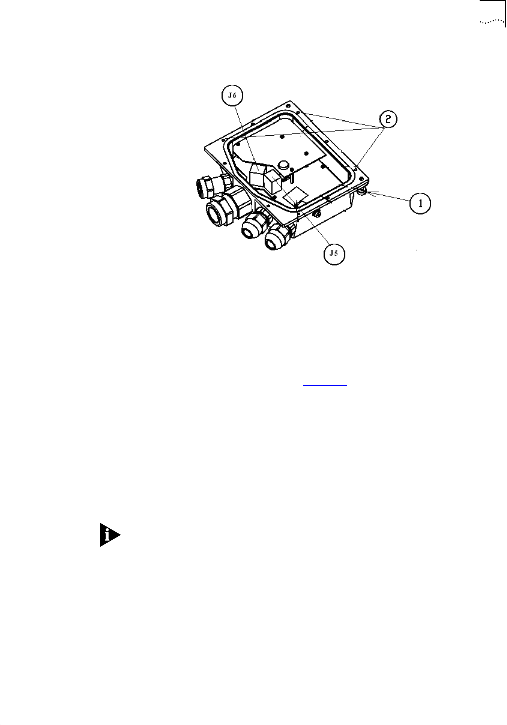
Cabling Power Supply
57
Part Number D01309
MovingMedia™ 2000 iCell All IP Radio Access Network Macro Pole Mount BTS
July 2007
Installation and Initial Configuration Guide
Figure 14
LPU Box Assembly
1
Use flat screw driver to release bolts (1). (Refer to Figure 14)
2
The LPU should be dismounted before lifting the Macro Pole Mount BTS to its
desired location.
3
Use #2 Phillips Screw driver to release screws (2) and open the top LPU cover.
Connecting Cabinet
Ground
The LPU box assembly is shown in Figure 14.
To connect the cabinet ground:
1
Insert the stripped end of the earth GROUND wire into the earth ground terminal
(J5-3 or J5-4) up to the insulation. The earth ground terminal is labeled GND.
2
Tighten the ground terminal screw until the cable is firmly secured.
Connecting DC Cable
The LPU box assembly is shown in Figure 14.
Connect the DC power cables after the ground has been connected.
To connect the DC cable:
1
Insert the stripped end of the RETURN wire into the J5-1 or J5-2 terminals up to
the insulation. The RETURN terminal is labeled DC-48V.
2
Tighten the terminal screw until the cable is firmly secured.
3
Insert the stripped end of the POWER wire into the J6-1 or J6-2 terminals up to
the insulation. The POWER terminal is labeled DC+48V.
4
Tighten the terminal screw until the cable is firmly secured.
5
Insert the stripped end of the neutral or unused wire (if any) into the J6-3 or J6-4
terminals up to the insulation. The unused terminal is labeled NTRL.
6
Tighten the terminal screw until the cable is firmly secured.
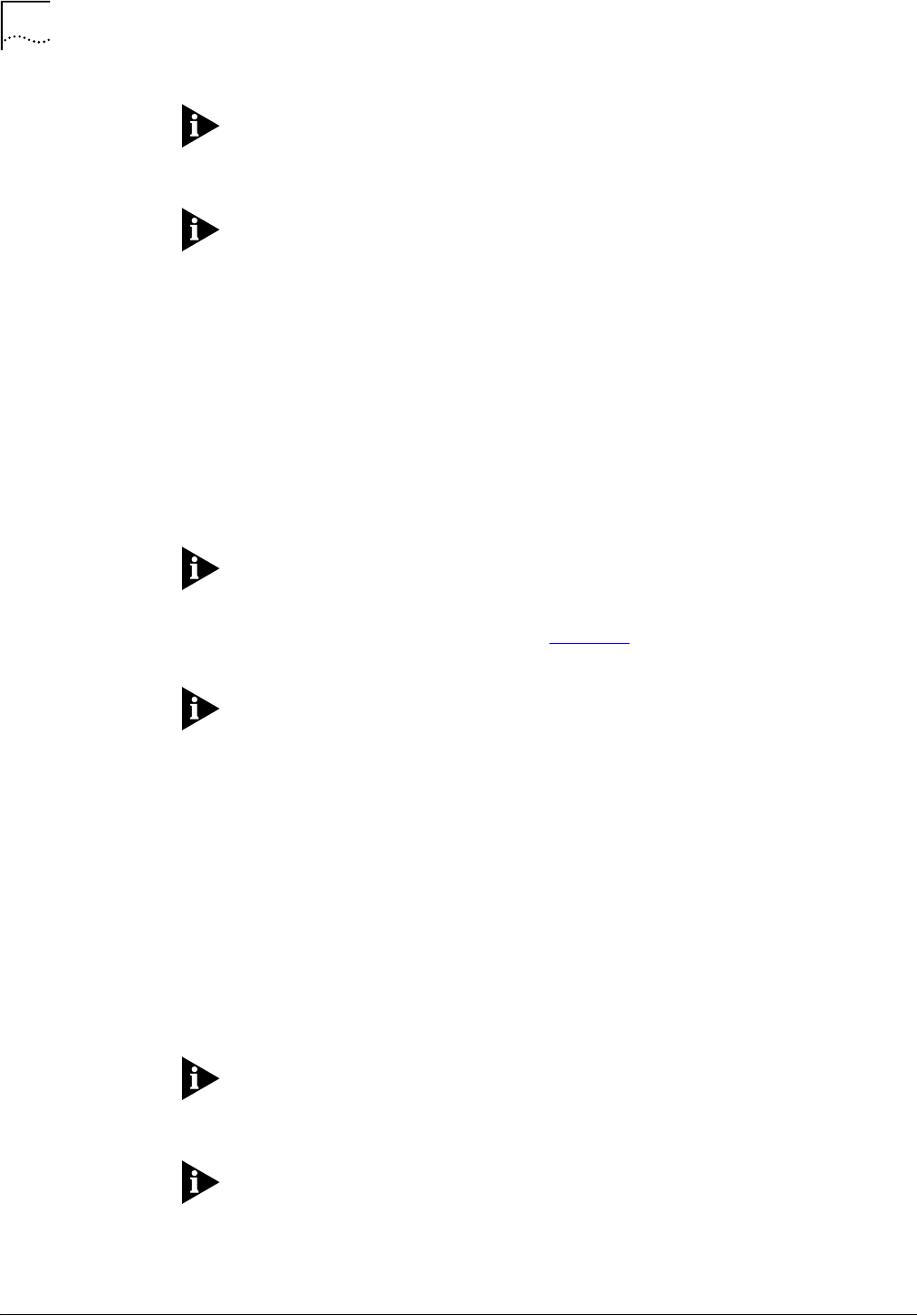
58
Chapter 3: Macro Pole Mount BTS Installation and Power Cabling
MovingMedia™ 2000 iCell All IP Radio Access Network Macro Pole Mount BTS
Part Number D01309
Installation and Initial Configuration Guide
July 2007
All DC power cables should terminate at the connectors J5 and J6 on the LPU
Box (Do not leave unconnected wires). The LPU distributes DC power to the
BTS components.
Connectors J5 and J6 are populated with two signals each (refer to on-board
silk titles for details).
7
The pins J5-1 and J5-2 are connected together and should be wired with -48
VDC from power source.
8
The pins J5-3 and J5-4 are connected together and should be wired to GND line
of power source.
9
The pins J6-1 and J6-2 are connected together and should be wired with +48
VDC from power source.
10
The pins J6-1 and J6-2 are connected together and should be wired with NTRL
neutral line from power source or the spare line of power cable.
All the lines in the proceeding procedure are lightning protected.
Connecting AC Cable
The LPU box assembly is shown in Figure 14.
Connect the AC power cables after the ground has been connected.
To connect the AC cable:
1
Insert the stripped end of the Neutral wire into the J5-1 or J5-2 terminals up to
the insulation. The RETURN terminal is labeled L2(N).
2
Tighten the terminal screw until the cable is firmly secured.
3
Insert the stripped end of the PHASE wire into the J6-1 or J6-2 terminals up to
the insulation. The POWER terminal is labeled L1.
4
Tighten the terminal screw until the cable is firmly secured.
5
Insert the stripped end of the neutral or unused wire (if any) into the J6-3 or J6-4
terminals up to the insulation. The unused terminal is labeled Spare.
6
Tighten the terminal screw until the cable is firmly secured.
All AC power cables should terminate at the connectors J5 and J6 on the LPU
Box (Do not leave unconnected wires). The LPU distributes DC power to the
BTS components.
Connectors J5 and J6 populated with two signals each (refer to on-board silk
titles for details).
7
The pins J5-1 and J5-2 are connected together and should be wired with L2(N)
from power source.

Cabling Power Supply
59
Part Number D01309
MovingMedia™ 2000 iCell All IP Radio Access Network Macro Pole Mount BTS
July 2007
Installation and Initial Configuration Guide
8
The pins J5-3 and J5-4 are connected together and should be wired to GND line
of power source.
9
The pins J6-1 and J6-2 are connected together and should be wired with L1
from power source.
10
The pins J6-1 and J6-2 are connected together and should be wired with Spare
line from power source or the spare line of power cable.
All the lines in the proceeding procedure are lightning protected.
Connecting Other
Cables
This section includes:
■
Connecting Ethernet and Console Cables
■
Installing Optional Sector Expansions
The BTS requires an ethernet connection to communicate with the BSC.
Configuration and monitoring processes require console cabling. Multi-sector
installation also requires console cabling (Refer to Connecting Ethernet and
Console Cables).
Connecting Ethernet and Console Cables
Figure 15 shows LPU board with Ethernet and two console connectors.
To connect the Ethernet and console cables:
1
Connect standard Category 5 Ethernet 10/100 cable (TIA/EIA-568-B) from
Ethernet switch to LPU Ethernet RJ45 connector.
2
When a break out box is used, connect Category 5 Ethernet 10/100 cable from
Console 1 connector (RJ45) on LPU board to break out box.
3
Both Ethernet and console cables must be routed within metal conduit with
ground connection to the top ground bar.
To maintain the IP67 rating of the product, all incoming cables attached to the
unit must provide a waterproof connection to the LPU.
The Ethernet and console fittings supplied with the Macro Pole Mount BTS
accepts a cable diameter in the range of 10mm to 14mm (0.4 to 0.54").
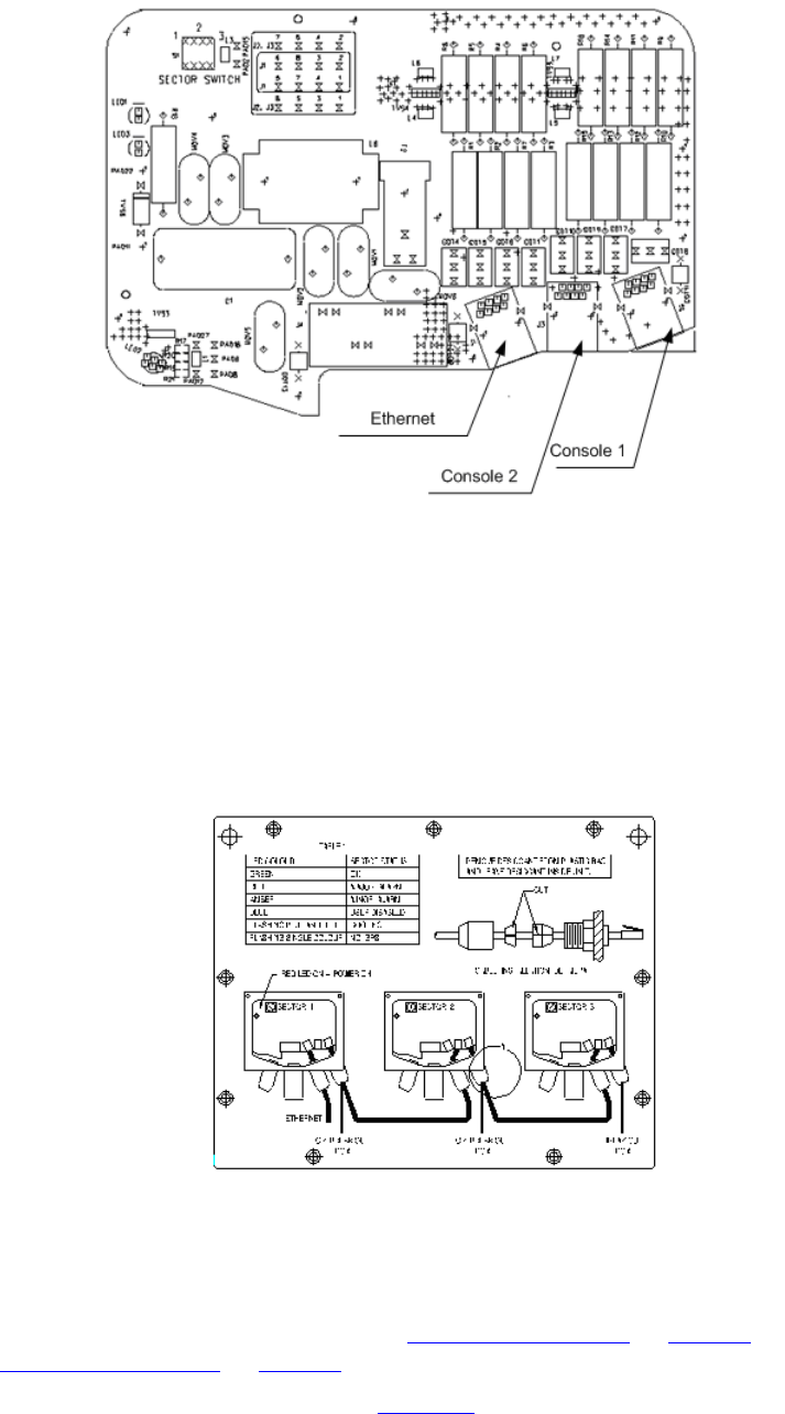
Figure 15
Location of Ethernet and Console Connectors on the LPU
Installing Optional Sector Expansions
The Macro Pole Mount BTS can support up to 3 sectors by adding iCell sector
expansion units.
Refer to Figures 13, 14, 15, and 16 for installation scheme.
Figure 16
Connecting Multi-sector Expansion Units (Ethernet and Console)
To connect iCell sector expansion units:
1
Stop the power to all sectors in the site.
2
For correct DC/AC cable wiring, refer to Connecting DC Cable on page 57, or
Connecting AC Cable on page 58, as required.
3
Connect console cables as shown in Figure 16.
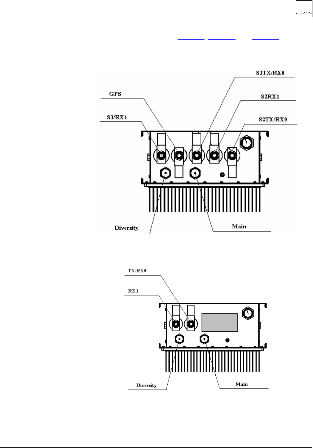
Cabling Power Supply
61
Part Number D01309
MovingMedia™ 2000 iCell All IP Radio Access Network Macro Pole Mount BTS
July 2007
Installation and Initial Configuration Guide
4
Connect RF cables as shown in Figure 17, Figure 18, and Figure 19.
Figure 17
Macro Pole Mount BTS (RF connection)
Figure 18
Macro Pole Mount BTS Sector Expansion (RF connection)
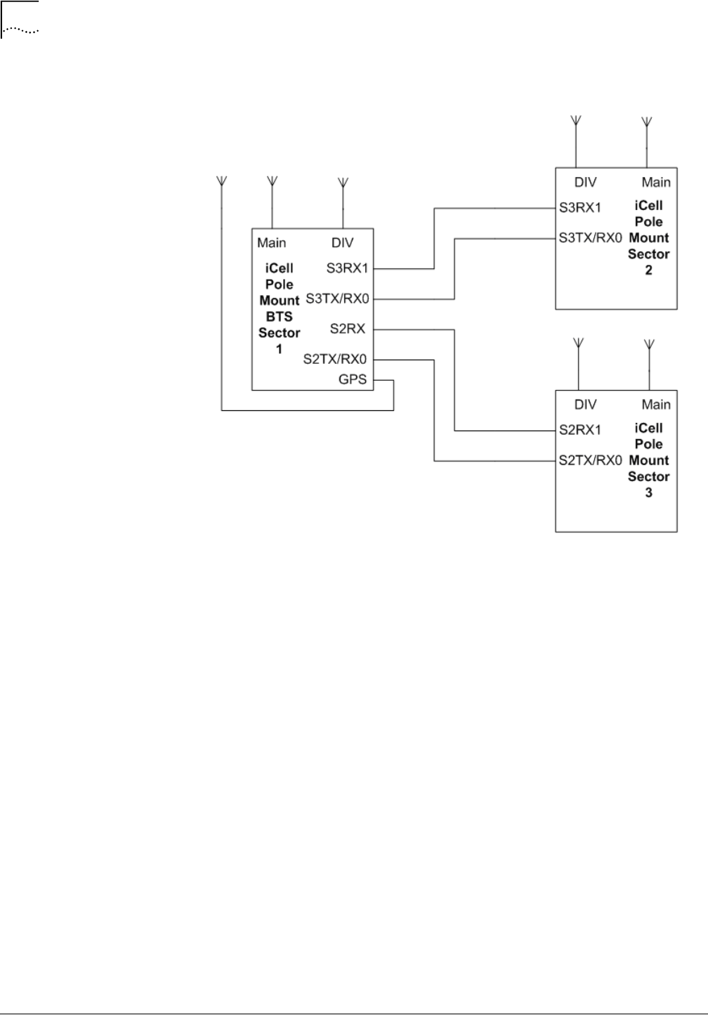
62
Chapter 3: Macro Pole Mount BTS Installation and Power Cabling
MovingMedia™ 2000 iCell All IP Radio Access Network Macro Pole Mount BTS
Part Number D01309
Installation and Initial Configuration Guide
July 2007
Figure 19
Macro Pole Mount BTS Multi-Sectors (RF connection)

Part Number D01309
MovingMedia™ 2000 iCell All IP Radio Access Network Macro Pole Mount BTS
July 2007
Installation and Initial Configuration Guide
4
T
RANSMISSION
, A
NTENNA
AND
GPS
C
ONNECTION
G
UIDELINES
About This Chapter
This chapter outlines guidelines for Voltage Standing Wave Ratio (VSWR),
Return Loss, Insertion Loss, and Antenna and GPS connections.
This chapter includes:
■
VSWR Guidelines
■
Return Loss Guidelines
■
Insertion Loss Guidelines
■
Antenna Connection
■
GPS Connection
VSWR Guidelines
This section discusses the importance of VSWR, antenna requirements, and
issues related to measuring VSWR. This section includes:
■
About VSWR
■
Antenna Requirements
■
Measuring VSWR
About VSWR
Voltage Standing Wave Ratio (VSWR) is the ratio of maximum to minimum
voltage in a standing wave pattern within a transmission line. VSWR measures
the impedance mismatch between the transmission line and its load. The
greater the mismatch the higher the VSWR. Minimum VSWR, where there is a
perfect impedance match, is unity.
VSWR is important because when two different transmission lines are
connected, there is a possibility of impedance mismatch. Impedance mismatch
will cause a direct loss in the power budget.
When the impedance of the two connecting transmission lines do not match, a
reflected wave is generated in the direction of the energy source. The voltage
(wave form) on the transmission line is a combination of the initial wave
(incident) and reflected wave.
Maximum power transfer across a connection is achieved when there is no
impedance mismatch (VSWR is low).

64
Chapter 4: Transmission, Antenna and GPS Connection Guidelines
MovingMedia™ 2000 iCell All IP Radio Access Network Macro Pole Mount BTS
Part Number D01309
Installation and Initial Configuration Guide
July 2007
Antenna Requirements
This guide does not describe how to install any GPS or RF antenna. This guide
assumes that any GPS or RF antenna has already been installed according to
manufacturers' specification.
The antenna should be resonant with the operating frequency so that its
impedance matches the impedance of the transmission lines. Coaxial lines with
50 ohm impedance characteristics are universally used, The antenna should be
designed to a 50 ohm terminal impedance.
Maximum power transmission over coaxial occurs when VSWR is unity
(antenna impedance is 50 ohm). Many antennae are specified to operate with a
VSWR lower than 1.5:1.
Measuring VSWR
Gain is the ratio of output power (voltage) to input power (voltage). Gain is
usually expressed in dB. If the ratio is less than unity, the gain, expressed in dB,
will be negative, indicating a loss between input and output.
Gain cannot be easily measured in the field, but antenna VSWR can be
measured at installation time.
The real (true) VSWR occurs at the antenna terminals, and VSWR should be
measured at the bulkhead. The VSWR at the end of the transmission line will be
lower than the real VSWR by the amount of attenuation (loss of signal power) in
the line.
VSWR below 1.2 should be measured with a spectrum analyzer. VSWR above
1.2 can be calculated using return loss values (refer to Calculating Return Loss)
and the appropriate table, or graph.
Figure 20 shows the Return Loss vs VSWR curve, which is useful for estimating
VSWR above 1.2.
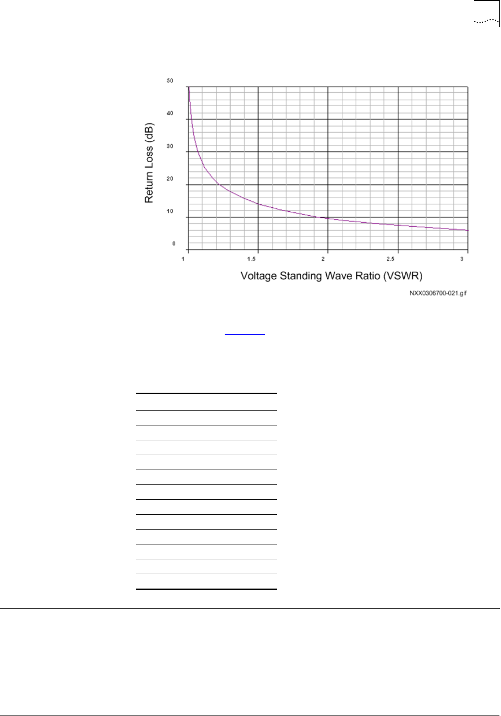
Return Loss Guidelines
65
Part Number D01309
MovingMedia™ 2000 iCell All IP Radio Access Network Macro Pole Mount BTS
July 2007
Installation and Initial Configuration Guide
Figure 20
Return Loss vs VSWR Curve
Consulting a VSWR and Return Loss table will give precise VSWR for a known
Return Loss value. Table 20 shows selected Return Loss and VSWR values,
approximating the desired VSWR range for the antenna cabling.
Return Loss
Guidelines
Return Loss is the ratio of the amplitude of the reflected wave to the amplitude
of the incident wave, measured at the junction of a transmission line and a
terminating impedance (or other discontinuity).
Return loss is a measure of the dissimilarity between impedances in metallic
transmission lines and loads, or between refractive indices in optical fibers.
Return loss is usually expressed in dB.
Table 20
Selected Return Loss and VSWR Values
Return Loss (RL) dB VSWR
13.98 1.50
14.26 1.48
14.56 1.46
14.88 1.44
15.21 1.42
15.56 1.40
15.94 1.38
16.33 1.36
16.75 1.34
17.21 1.32
17.69 1.30
18.22 1.28
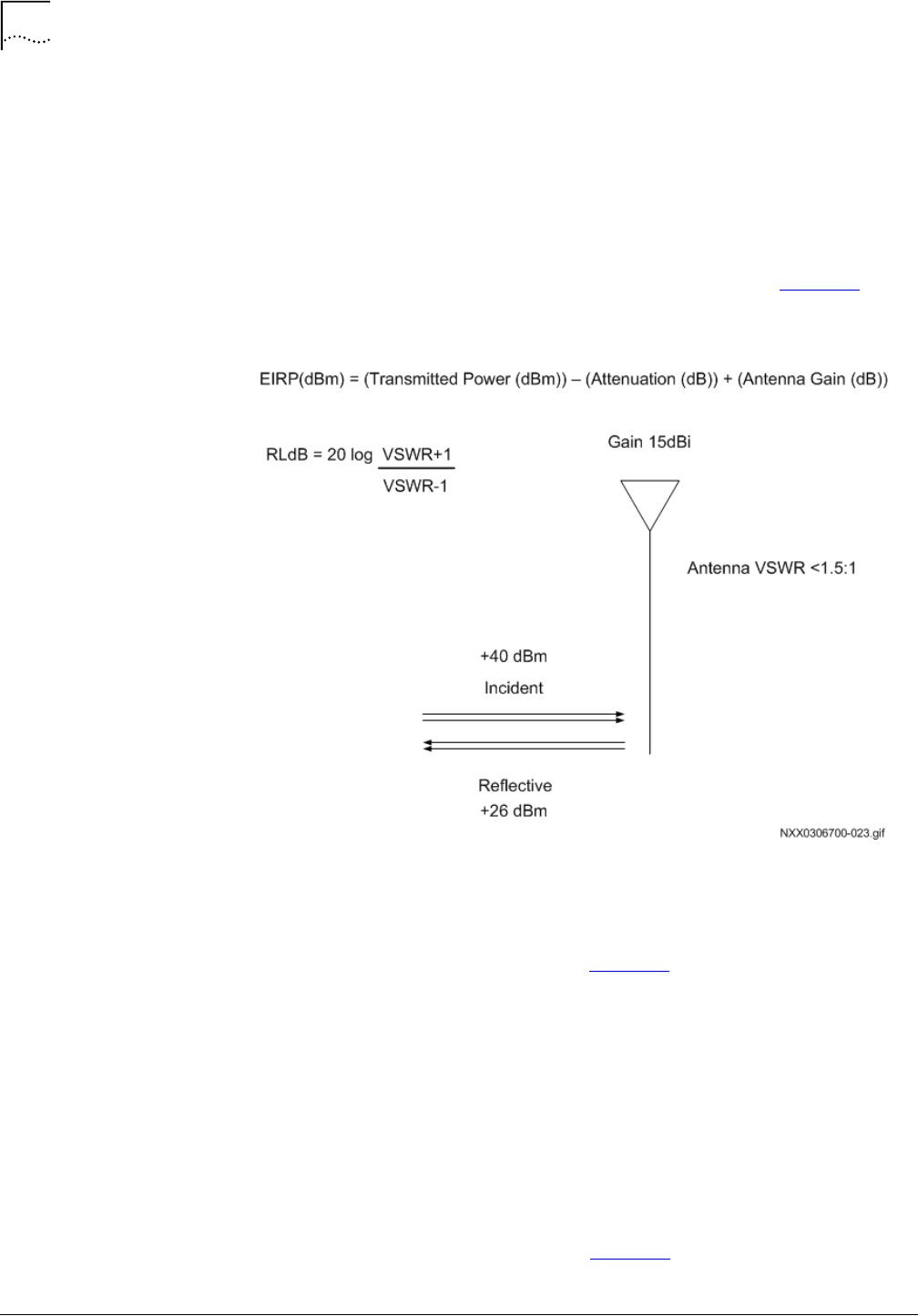
66
Chapter 4: Transmission, Antenna and GPS Connection Guidelines
MovingMedia™ 2000 iCell All IP Radio Access Network Macro Pole Mount BTS
Part Number D01309
Installation and Initial Configuration Guide
July 2007
Calculating Return Loss
Return Loss calculations can be expressed in dBm or dBw. Decibels are used to
express the ratio between two quantities. dBm uses a reference of 1mW and
dBw uses a reference of 1W.
dBm = 10 log(power out / 1mW)
dBw = 10 log(power out / 1W)
A Return Loss (metallic transmission line) scenario is shown in Figure 21.
Figure 21
Return Loss Calculation Scenario
40dBm power (incident) is equivalent to 10 watts, and 26 dBm (reflective) is
equivalent to 400mW.
Using the equation and values shown in Figure 21, Return Loss is calculated at
14dB.
The Effective Isotropically Radiated Power (EIRP) is used to estimate the
service area of the transmitter, and to co-ordinate transmitters on the same
frequency so that their coverage areas do not overlap.
Effective Isotropically Radiated Power (EIRP) is given by:
EIRP(dBm) = (Transmitted Power (dBm)) – (Attenuation (dB)) + (Antenna Gain
(dB)).
Using the equation and values shown in Figure 21, EIRP is calculated at 39.8
dBm + antenna gain (decibels of gain of an antenna is expressed as dBi).

Insertion Loss Guidelines
67
Part Number D01309
MovingMedia™ 2000 iCell All IP Radio Access Network Macro Pole Mount BTS
July 2007
Installation and Initial Configuration Guide
Insertion Loss
Guidelines
Insertion Loss is the power loss resulting from the insertion of a device in a
transmission line. Insertion Loss expressed as the reciprocal of the ratio of the
signal power delivered to that part of the line before the device to the signal
power delivered to that same part after the device. The inserted device is some
type of connector.
Calculating Insertion
Loss
Calculation of Insertion loss requires known incident and reflected power
values. The incident power should be known and reflected power is calculated
as Return Loss.
Insertion Loss is given by:
L
insertion
(dB) = 10
log
(P
out
/P
in
)
Using the scenario shown in Figure 21, where the incident power is 10 W
(40dBm), reflected power is 0.4 W (26dBm), the total power output is 9.6 W.
Insertion Loss is 10
log
(9.6/10) or 0.2dB.
Antenna Connection
To connect antenna cables:
1
Confirm that the antenna cables are labeled near the Macro Pole Mount BTS
terminating end. Label the cables if they are not already labeled.
2
Thread the 7-16 Din type connector end of the MAIN cable onto the 7-16 DIN
connector end on the antenna connection plate.
3
Thread the 7-16 Din type connector end of the DIVERSITY cable onto the 7-16
DIN connector end on the antenna connection plate.
GPS Connection
The GPS connection requires guidelines for timing information and for
connecting the GPS cable to the Macro Pole Mount BTS.
About GPS in BTS
A BTS requires accurate timing information for both Time of Day (ToD) and
message synchronization.
The Global Positioning System (GPS) is a constellation of 27 Earth-orbiting
satellites (24 in operation and three extras in case one fails). A GPS receiver
must locate four or more of these satellites, determine the distance to each, and
use this information to deduce its own location. This operation is based on
trilateration.
The GPS receiver and satellite both need clocks that can be synchronized to the
nanosecond. Every satellite contains an atomic clock and the GPS receiver
itself uses an ordinary quartz clock, which it constantly resets.
The receiver looks at incoming signals from four or more satellites and gauges
its own inaccuracy - there is only one value for the "current time" that the

68
Chapter 4: Transmission, Antenna and GPS Connection Guidelines
MovingMedia™ 2000 iCell All IP Radio Access Network Macro Pole Mount BTS
Part Number D01309
Installation and Initial Configuration Guide
July 2007
Warning:
Warning:
receiver can use. The correct time value will cause all of the signals that the
receiver is receiving to align at a single point in space. That time value is the
time value held by the atomic clocks in all of the satellites. So the receiver sets
its clock to that time value, and it then has the same time value that all the
atomic clocks in all of the satellites have.
Connecting GPS Cable
to Macro Pole Mount
BTS
A GPS antenna connection point is provided on the bottom of the Macro Pole
Mount BTS.
Connecting GPS Cable
The Macro Pole Mount BTS integrated GPS cable uses an N type connector
end. The N-type jack (female) connector allows the connection of a
non-integrated GPS connector.
To connect an external GPS antenna cable:
1
Disconnect the existing GPS antenna cable from the bottom of the Macro Pole
Mount BTS.
2
Thread the GPS cable end behind the sunshield panes and secure it.
3
Connect the external GPS antenna cable (N-type plug (male)) to the GPS
connector on the bottom of the Macro Pole Mount BTS.
Do not over tighten connector.
The GPS antenna is active. Any DC blocking components on the GPS antenna
cable (such as DC block or attenuators) will prevent proper antenna power
feeding.

Part Number D01309
MovingMedia™ 2000 iCell All IP Radio Access Network Macro Pole Mount BTS
July 2007
Installation and Initial Configuration Guide
5
P
OWERING
O
N
AND
O
FF
About This Chapter
This chapter describes how to power on and off the system and start up the
software. It also describes verification procedures to be performed before
applying power.
This chapter includes:
■
Before Powering On
■
Powering On
■
BTS Sector Table
Before Powering On
Before powering on the Macro Pole Mount BTS:
■
Ensure the two power connections to the two DC/AC power inputs have been
made
■
Check that the Macro Pole Mount BTS is properly grounded and that the
hardware connections are tightened at both ends of the cable
■
Check that all the required cables are connected properly.
Powering On
Powering on the system consists of:
■
Connecting to the BSC
■
Checking Status of BSC
■
Checking BSC Application Status
■
Supplying power to BTS
■
Checking Status of the BTS and BTS Sectors
Connecting to the BSC
Logging in and checking the status of the BSC application requires a connection
to the BSC:
■
An Ethernet or serial connection can be used to connect to the BSC. Some
BSC implementations may require secure shell (SSH) connection. For a SSH
connection, use a Telnet client that supports SSH and is configured to use
port 22 instead of port 23.

70
Chapter 5: Powering On and Off
MovingMedia™ 2000 iCell All IP Radio Access Network Macro Pole Mount BTS
Part Number D01309
Installation and Initial Configuration Guide
July 2007
To connect to the BSC using an Ethernet connection:
1
Connect to the BSC using Telnet or SSH:
a
To Telnet to the BSC:
> telnet
<BSC IP Address>
Login as icell
b
To SSH to the BSC using the target username:
>
ssh target@<BSC IP address>
target@<BSC IP address>'s password:
[target@<hostname> target]$
Change to the root user:
>
su - root
[root@<BSC Name> root]#
Checking Status of BSC
Check the status of the BSC. The BSC should be both operational (enabled)
and unlocked.
To check BSC status:
1
Connect to the BSC Element Manager, using HTTP GUI interface.
2
Select
cdma1x
to the right of GUI interface
,
then select
bscOperationalState
.
3
Confirm that the bscOperationalState is enabled.
4
Select
cdma1x,
then
bscAdministrativeState.
5
Verify that the bscAdministrativeState is Unlocked.
Checking BSC
Application Status
To check the BSC application status:
1
Enter icell_bsc status to view application status:
[icell@bsc7 icell]$icell_bsc status
Table 21
Default BSC Login Parameters
Parameter Value
Default IP address
10.10.10.10
icell
Password
icell
root
Password
tel os
user
target target

Powering On
71
Part Number D01309
MovingMedia™ 2000 iCell All IP Radio Access Network Macro Pole Mount BTS
July 2007
Installation and Initial Configuration Guide
The BSC application should display
started
. Refer to Example: BSC Application
Status Check Session for an example Session.
If the BSC application is not started, then start it as described in Starting the
BSC Application.
Starting the BSC Application
To start the BSC application:
1
Connect and login to the BSC. Refer to Connecting to the BSC.
2
Start the application
[icell@bsc7 icell]$ icell_bsc start
Check that the application is started
[icell@bsc7 icell]$icell_bsc status
Testing Ethernet Connectivity
To test Ethernet connectivity:
1
Test IP connectivity between the test client and the BSC and BTS.
> ping <BSC IP Address>
> ping <BTS IP Address>
2
Close any BSC or BTS Element Manager connections.
Supplying power to BTS
To supply power to the BTS:
1
Make sure the power supply to the Macro Pole Mount BTS is
ON
.
2
Confirm visually that the power indicator on each Macro Pole Mount BTS power
supply is lit.
3
Wait approximately one minute for the BTS to complete the boot process.
Bringing the Macro Pole
Mount BTS into Service
The Macro Pole Mount BTS is brought into service by unlocking the BSC, BTS,
and then each BTS sector. The Macro Pole Mount BTS is fully in service when
all sectors have blossomed.
Example: BSC Application Status Check Session
Red Hat Linux release 8.0 (Psyche)
Kernel 2.4.18-14 on an i686
login: icell
Password:
Last login: Mon Jan 27 12:19:20 from 10.10.1.13
[icell@bsc7 icell]$icell_bsc status
Status bsc_lxrel: started
21859
21864
[icell@bsc7 icell]$
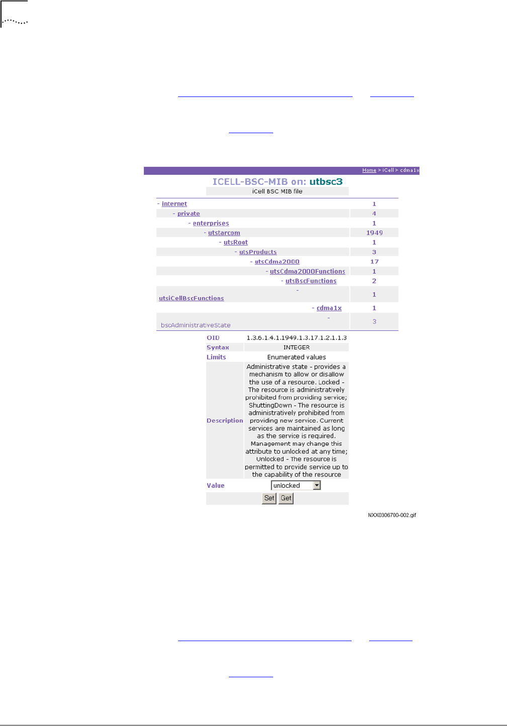
72
Chapter 5: Powering On and Off
MovingMedia™ 2000 iCell All IP Radio Access Network Macro Pole Mount BTS
Part Number D01309
Installation and Initial Configuration Guide
July 2007
To unlock the BSC:
1
Connect to the BSC Element Manager.
Refer to Connecting to BSC Element Manager on page 123.
2
On the menu, click
cdma1x
and then click
bscAdministrativeState
.
The page shown in Figure 22 appears.
Figure 22
Unlock BSC
3
Select
unlocked
from the
Value
dropdown menu and then click
Set
.
The BSC is now in service.
To unlock the BTS:
1
Connect to the BTS Element Manager.
Refer to Connecting to BTS Element Manager on page 123.
2
On the menu, click
cdma1x
and then click
btsAdministrativeState
.
The page shown in Figure 23 appears.
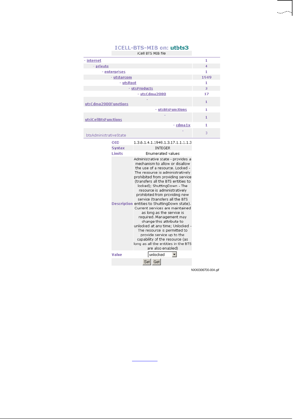
Powering On
73
Part Number D01309
MovingMedia™ 2000 iCell All IP Radio Access Network Macro Pole Mount BTS
July 2007
Installation and Initial Configuration Guide
Figure 23
Unlock BTS
3
Select
unlocked
from the
Value
dropdown menu and then click
Set
.
The BTS is now in service.
4
Keep the connection to the BTS Element Manager for the next step.
To unlock the BTS sector:
1
In the BTS Element Manager, click
cdma1x
,
cdma
,
cdmaSectorInfo
, and then
sectorInfoTable
.
The page shown in Figure 24 appears.
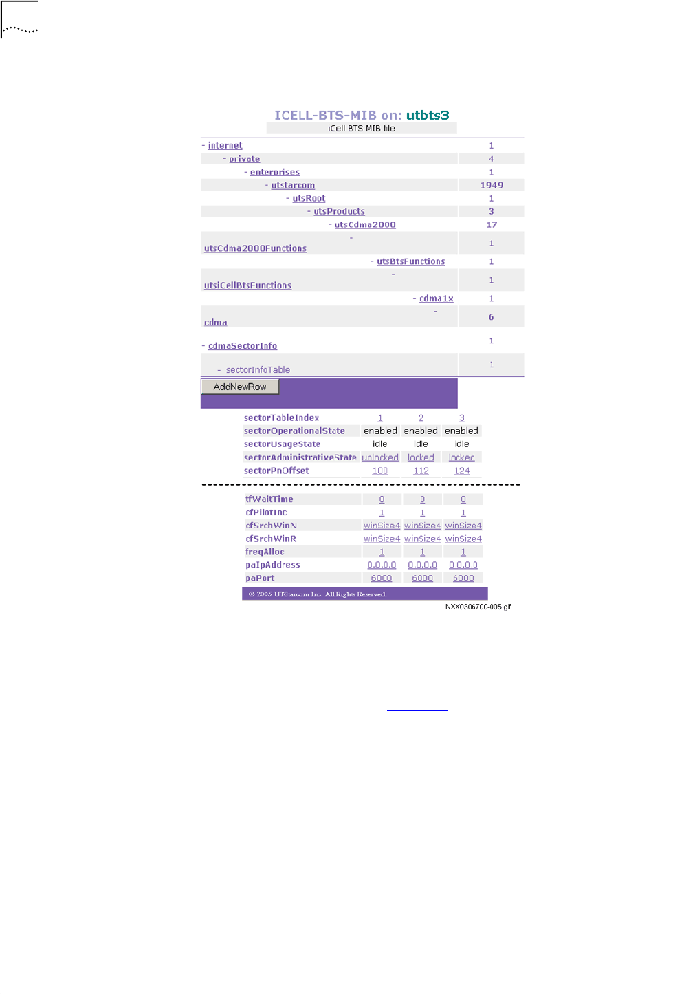
74
Chapter 5: Powering On and Off
MovingMedia™ 2000 iCell All IP Radio Access Network Macro Pole Mount BTS
Part Number D01309
Installation and Initial Configuration Guide
July 2007
Figure 24
BTS Sector Table
2
For sector 1, click
locked
in the first column of the
sectorAdministrativeState
row.
A page similar to that shown in Figure 25 appears.
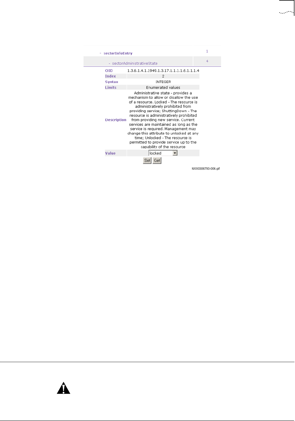
Powering Off
75
Part Number D01309
MovingMedia™ 2000 iCell All IP Radio Access Network Macro Pole Mount BTS
July 2007
Installation and Initial Configuration Guide
Figure 25
Unlock BTS Sectors
3
Select
unlocked
from the
Value
dropdown menu and then click
Set
.
The BTS sector is now in service.
4
Keep the connection to the BTS Element Manager for the next step.
Checking Status of the
BTS and BTS Sectors
Check the status of the BTS, and BTS sector after the sector has blossomed.
The BTS and sector should be both operational (enabled) and unlocked.
To check the BTS and sector status:
1
On the BTS Element Manager, click
cdma1x
and then
btsOperationalState
.
2
Verify that the
btsOperationalState
is
Enabled
.
3
Click
cdma1x
and then
btsAdministrativeState
.
4
Verify that the
btsAdministrativeState
is
Unlocked
.
5
Click
cdma1x
,
cdma
,
cdmaSectorInfo
, and then
SectorInfoTable
.
6
Verify that the
sectorOperationalState
for each sector is
Enabled
.
7
Verify that the
sectorAdministrativeState
for each sector is
Unlocked
.
8
Exit the BTS Element Manager.
Powering Off
Make sure the power supply to the Macro Pole Mount BTS is disabled before
any installation or maintenance activity.

76
Chapter 5: Powering On and Off
MovingMedia™ 2000 iCell All IP Radio Access Network Macro Pole Mount BTS
Part Number D01309
Installation and Initial Configuration Guide
July 2007
To power off the BTS:
1
Lock the BTS sectors. Refer to BTS Sector Table.
2
Lock the BTS. Refer to Locking BTS.
3
Lock the BSC. Refer to Locking BSC.
4
Stop the BSC application. Refer to Stopping the BSC Application.
5
Shutdown the BSC. Refer to Shutting Down BSC.
Locking BTS Sectors
Locking a BTS sector takes it out of service.
To Lock all BTS sectors:
1
Connect the test client to the Ethernet switch.
2
Connect to the BTS Element Manager. Refer to Connecting to BTS Element
Manager on page 163.
3
On the menu, click
cdma1x
,
cdma
,
cdmaSectorInfo
, and then
sectorInfoTable
.
The page shown in Figure 26 appears.
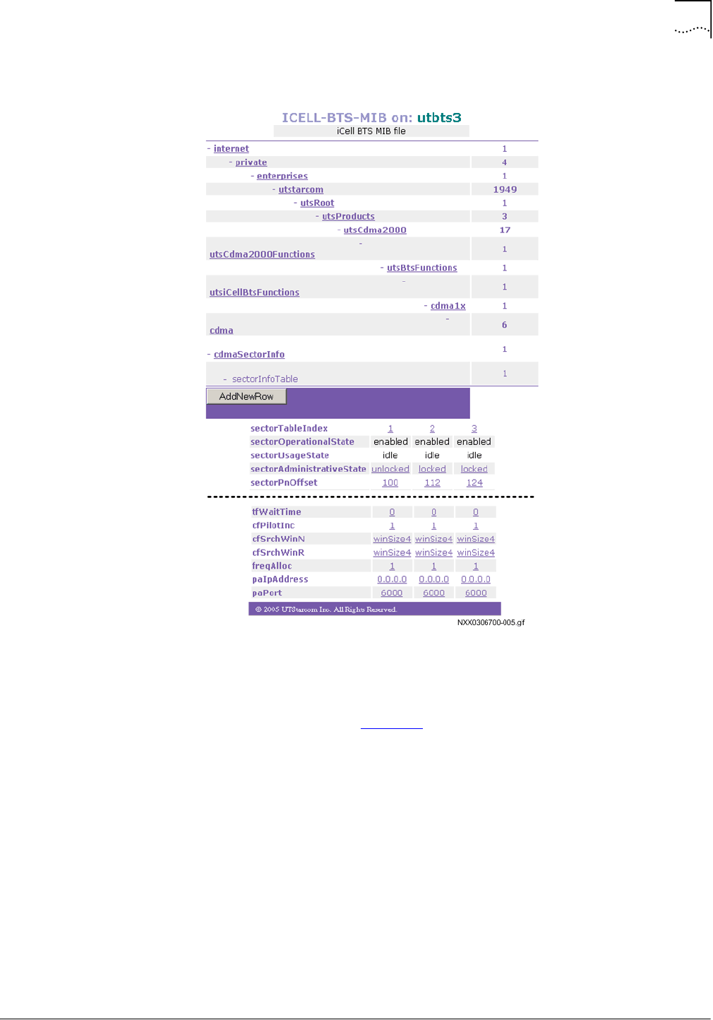
Powering Off
77
Part Number D01309
MovingMedia™ 2000 iCell All IP Radio Access Network Macro Pole Mount BTS
July 2007
Installation and Initial Configuration Guide
Figure 26
BTS Sector Table
4
For sector 1, click
Unlocked
in the first column of the
sectorAdministrativeState
row.
A page like that shown in Figure 27 appears.

78
Chapter 5: Powering On and Off
MovingMedia™ 2000 iCell All IP Radio Access Network Macro Pole Mount BTS
Part Number D01309
Installation and Initial Configuration Guide
July 2007
Figure 27
Lock BTS Sectors
5
Select
Locked
from the dropdown menu and then click
Set
.
The BTS sector is now out of service.
6
Keep the connection to the BTS Element Manager for the next step.
Locking BTS
Wait until the BTS is completely wilted before locking it.
To lock the BTS:
1
In the BTS Element Manager, click
cdma1x
, and then
btsAdministrativeState
.
A page similar to that shown in Figure 28 appears.
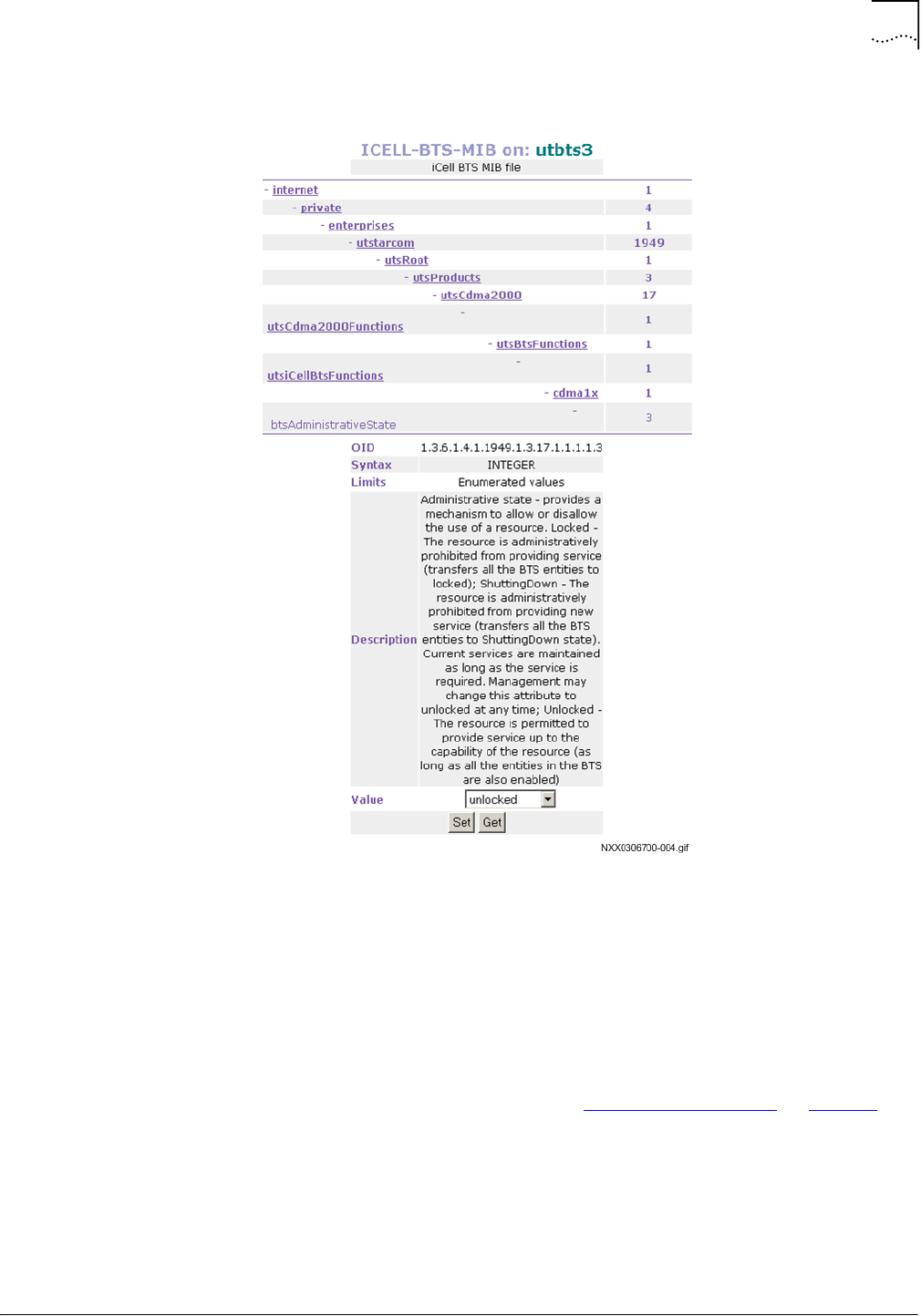
Powering Off
79
Part Number D01309
MovingMedia™ 2000 iCell All IP Radio Access Network Macro Pole Mount BTS
July 2007
Installation and Initial Configuration Guide
Figure 28
Lock BTS
2
Select
Locked
from the dropdown menu and then click
Set
.
The BTS is now out of service.
3
Exit the BTS Element Manager.
Stopping the BSC
Application
To stop the BSC application:
1
Connect and login to the BSC. Refer to Connecting to the BSC on page 69.
2
Stop BSC application
[icell@bsc7 icell]$ icell_bsc stop
3
Confirm that BSC application is
stopped.
[icell@bsc7 icell]$ icell_bsc status
4
Keep the Telnet session open for a further procedure.

80
Chapter 5: Powering On and Off
MovingMedia™ 2000 iCell All IP Radio Access Network Macro Pole Mount BTS
Part Number D01309
Installation and Initial Configuration Guide
July 2007
The application should be
stopped
.
Refer to Example: Stop BSC Application for an example session.
Example: Stop BSC Application
Red Hat Linux release 8.0 (Psyche)
Kernel 2.4.18-14 on an i686
login: icell
Password:
Last login: Mon Jan 27 12:19:20 from 10.10.1.13
[icell@bsc7 icell]$ icell_bsc stop
Shutting down bsc_lxrel: ...
[icell@bsc7 icell]$ icell_bsc status
Status bsc_lxrel: stopped
[icell@bsc7 icell]$
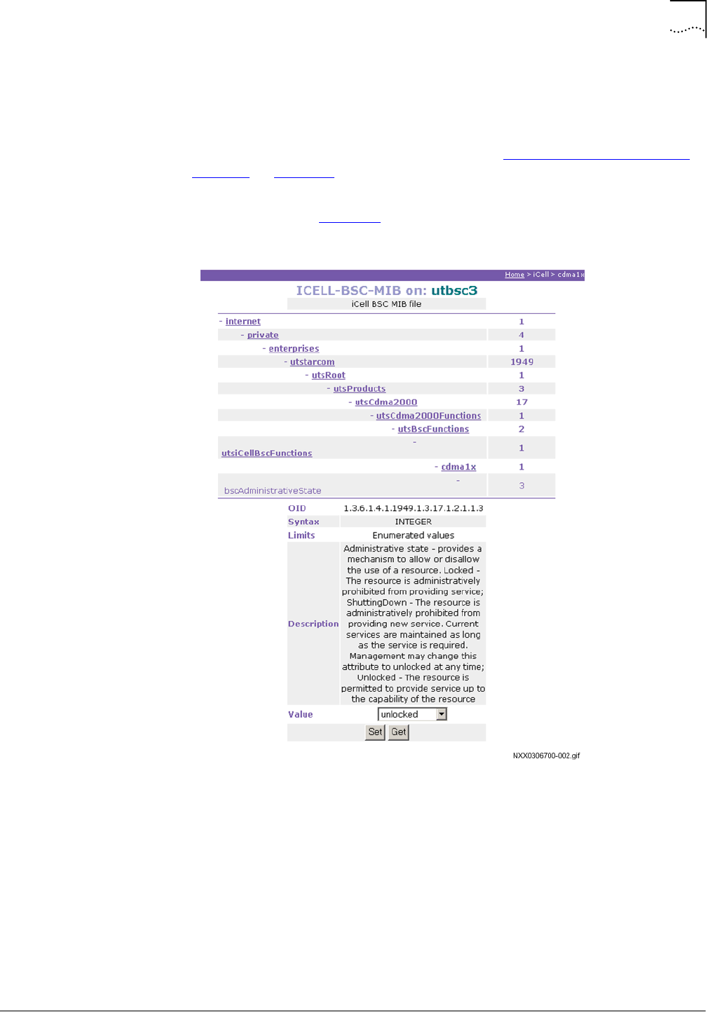
Powering Off
81
Part Number D01309
MovingMedia™ 2000 iCell All IP Radio Access Network Macro Pole Mount BTS
July 2007
Installation and Initial Configuration Guide
Locking BSC
Lock the BSC to take it out of service.
To lock the BSC:
1
Connect to the BSC Element Manager. Refer to Connecting to BSC Element
Manager on page 163.
2
On the menu, click
cdma1x
and then
bscAdministrativeState
.
The page shown in Figure 29 appears.
Figure 29
Lock BSC
3
Select
Locked
from the dropdown menu and then click
Set
.
The BSC is now out of service.
4
Exit the BSC Element Manager.
Shutting Down BSC
To shut down the BSC:
1
Using the
root
telnet
session, shutdown the BSC.
[root@<BSC Name> root]#
init 0
2
Monitor standard output until
Power off
is displayed.

82
Chapter 5: Powering On and Off
MovingMedia™ 2000 iCell All IP Radio Access Network Macro Pole Mount BTS
Part Number D01309
Installation and Initial Configuration Guide
July 2007
3
Exit the
telnet
session.

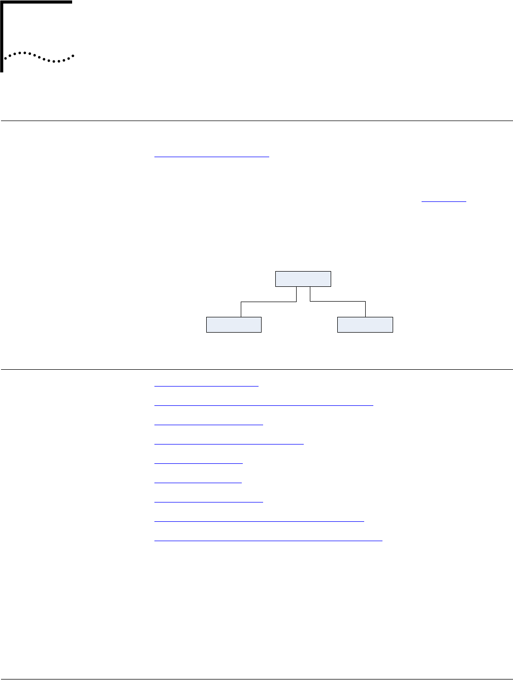
Part Number D01309
MovingMedia™ 2000 iCell All IP Radio Access Network Macro Pole Mount BTS
July 2007
Installation and Initial Configuration Guide
6
C
ONFIGURATION
About This Chapter
This chapter includes:
■
Configuration Procedure
The Macro Pole Mount BTS ships with its component network elements
pre-configured with non-routable IP addresses, as shown in Figure 30. This
chapter describes how to change to addresses that are routable on your
network.
Figure 30
Macro Pole Mount BTS Shipping Configuration
Configuration
Procedure
■
Configuring a Test PC
■
Connecting the Test PC to the Ethernet Switch
■
Performing Ping Test 1
■
Configuring the Ethernet Switch
■
Configure the BSC
■
Configure the BTS
■
Performing Ping Test 2
■
Configuring the Macro Pole Mount BTS GPS
■
Confirming the External GPS Feature is Enabled
Configuring a Test PC
Configure a test PC with two IP addresses. One IP address should be valid on
the shipping network and the other on your network.
Ethernet Switch
BSC BTS10.10.10.10 10.10.10.20 - 23
10.10.10.2
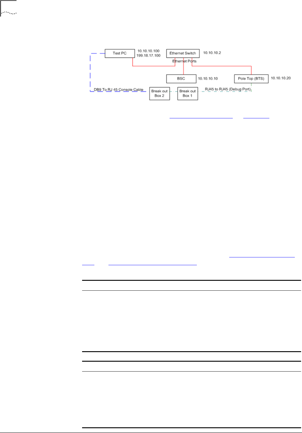
86
Chapter 6: Configuration
MovingMedia™ 2000 iCell All IP Radio Access Network Macro Pole Mount BTS
Part Number D01309
Installation and Initial Configuration Guide
July 2007
Figure 31
Example Test PC IP Configuration
To Configure a Test PC refer to Configuring Test Client on page 115.
Connecting the Test PC
to the Ethernet Switch
Connect an Ethernet cable from a port on the Test PC to an empty port on the
Ethernet Switch.
Performing Ping Test 1
Ping each of the network elements on the shipping network.
To perform the ping test:
1
From the Test PC, click
Start
|
Run
.
2
Enter
cmd
.
3
Ping the Ethernet Switch:
ping 10.10.10.2
4
Ping the BSC:
ping 10.10.10.10
5
Ping BTS1:
ping 10.10.10.20
Resolve any connectivity problems you find. Refer to Example: A Successful
Ping and Example: An Unsuccessful Ping.
Example: A Successful Ping
H:\>ping 10.10.10.2
Pinging 10.10.10.2 with 32 bytes of data:
Reply from 10.10.10.2: bytes=32 time<1ms TTL=128
Reply from 10.10.10.2: bytes=32 time<1ms TTL=128
Reply from 10.10.10.2: bytes=32 time<1ms TTL=128
Reply from 10.10.10.2: bytes=32 time<1ms TTL=128
Ping statistics for 10.10.10.2:
Packets: Sent = 4, Received = 4, Lost = 0 (0% loss),
Approximate round trip times in milli-seconds:
Minimum = 0ms, Maximum = 0ms, Average = 0ms
Example: An Unsuccessful Ping
H:\>ping 10.10.10.2
Pinging 10.10.10.2 with 32 bytes of data:
Request timed out.
Request timed out.
Request timed out.
Request timed out.
Ping statistics for 10.10.10.2:
Packets: Sent = 4, Received = 0, Lost = 4 (100% loss),
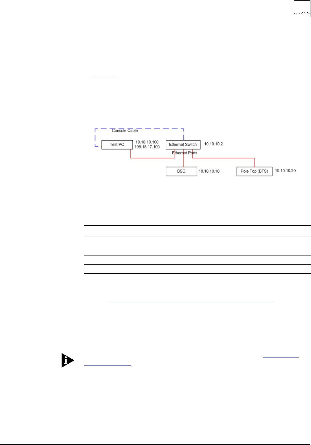
Configuration Procedure
87
Part Number D01309
MovingMedia™ 2000 iCell All IP Radio Access Network Macro Pole Mount BTS
July 2007
Installation and Initial Configuration Guide
Configuring the Ethernet
Switch
To configure the Ethernet switch:
1
Set up the serial connection from the Test PC to the Ethernet Switch as shown
in Figure 32.
2
Configure the IP settings using the Ethernet Switch commands prompt or its http
interface.
Figure 32
Setting Up the Serial Connection to the Ethernet Switch
Changing the IP Address of the Ethernet Switch
Refer to Example: Changing the IP Address of the Ethernet Switch.
1
From the
Switch>
prompt, enter
en
.
2
For
password:
, enter
tel os
.
3
Enter
ip address <new_address> <new_subnetmask>
If the switch responds with set ip addr error, follow the steps in Resetting to
Factory Defaults.
4
Enter
ip gateway <gateway_address>
5
Check the configuration: enter
show switch
.
6
Enter
save
.
7
Enter
exit
.
Table 22
Element Serial Configuration
Device BPS Bits/char Stop Bit Parity Bit
Switch Lenovo: 38400
Cisco: 9600
8None 1
BSC 38400 8None 1
Pole Top (1xBTS) 38400 8None 1

88
Chapter 6: Configuration
MovingMedia™ 2000 iCell All IP Radio Access Network Macro Pole Mount BTS
Part Number D01309
Installation and Initial Configuration Guide
July 2007
Optionally, the IP address of the Ethernet Switch through its http interface can
be changed. Open a web browser and enter the URL http://10.10.10.2.
Resetting to Factory Defaults
Perform these steps only if the Ethernet Switch responds with
set ip addr
error
.
1
From the
Switch#
, type
reset factory
.
2
When asked to continue, enter
y
.
The switch resets.
3
Check whether the password is set up: enter
en
.
■
If
password:
appears, the password is set up correctly.
■
If
Switch#
appears, do the following:
a
Enter
password
.
b
At
new password:
, enter
tel os
.
c
At
re-type password:
, enter
tel os
.
Configure the BSC
Telnet to the BSC and edit its configuration files.
1
Connect serial cable from PC to breaker out box #2
2
Open up Hyper-terminal with Macro Pole Mount BTS setting
3
Telnet to the new BSC address.
4
Log in as
target
, password
target
.
5
Switch to root user:
su root
, password
tel os
.
6
Enter
cd /etc
.
7
Enter
cp bsc1.cfg bsc1.cfg.bak
.
8
Enter
chmod 666 bsc1.cfg
.
9
Start a web browser and enter
http://<new_bsc_address>
.
10
Log in as
icell
, password
icell
.
Example: Changing the IP Address of the Ethernet Switch
Switch> en
password: tel os
Switch# ip address 199.18.17.2 255.255.255.0
Switch# ip gateway 199.18.17.1
Switch# save
Switch# show switch
Ip Address : 199.18.17.2
Subnet Mask : 255.255.255.0
Default Gateway : 199.18.17.1
MAC Address : 00:09:ca:14:94:10
Spanning Tree : Disable
IGMP Snooping : Disable
Switch# exit
Switch> <exit>

Configuration Procedure
89
Part Number D01309
MovingMedia™ 2000 iCell All IP Radio Access Network Macro Pole Mount BTS
July 2007
Installation and Initial Configuration Guide
11
From the http interface to the BSC, click
cdma1x
|
interfaces
|
sntp
|
sntpServerIp
. Change Value to a BTS IP address, then click
Set
.
12
Click
Commands
|
commandSaveAndRestart
. Select
action
, then click
Set
.
13
Telnet to the new BSC address.
14
Log in as
target
, password
target
.
15
Switch to root user:
su root
, password
tel os
.
16
Enter
cd /etc
.
17
Enter
vi hosts
. Change and add lines as necessary to list the new BSC and
BTS addresses.
18
Enter
cd /sbin
.
19
Enter
./init q
.
Configure the BTS
To configure the BTS:
1
Set up the serial connection to the BTS.
2
Configure the IP settings using the BTS command prompt and the http interface.
3
Repeat steps one and two for each additional BTS.
Configuring the Serial Connection to the BTS
1
Enter
bootChange
. The
boot device
line is revealed. Press Enter to reveal
each line. To change a line, type the new value to the right of the current value,
as shown in Example: The bootChange Command.
Example: Editing hosts
127.0.0.1 localhost.localdomain localhost
199.18.17.10 yourbsc1
199.18.17.20 yourbts1
199.18.17.21 yourbts2
...

90
Chapter 6: Configuration
MovingMedia™ 2000 iCell All IP Radio Access Network Macro Pole Mount BTS
Part Number D01309
Installation and Initial Configuration Guide
July 2007
2
After the bootChange is complete, enter
bts1xReset
.
3
Start a web browser and enter
http://<new_bts1_address>
.
4
Log in as
icell
, password
icell access
.
5
From the http interface to the BTS, click
cdma1x
|
interfaces
|
aBis
|
bscListTable
|
bscAddress
. Change Value to the BSC IP address, then click
Set
.
6
Click
Commands
|
commandSaveAndRestart
. Select
action
, then click
Set
.
Performing Ping Test 2
Ping each of the network elements on your network.
1
From the Test PC, click
Start
|
Run
.
2
Enter
cmd
.
3
Ping the Ethernet Switch:
ping <new_switch_address>
4
Ping the BSC:
ping <new_bsc_address>
5
Ping BTS1:
ping <new_bts1_address>
6
Resolve any connectivity problems.
Remember to change the IP address of the Test PC back to the value it had at
the start of this chapter.
Configuring the Macro
Pole Mount BTS GPS Enabling the GPS Feature on the BTS.
1
Connect to Management information Base (MIB).
2
Select
cdma1x
and click
hw,
then
gpsPeripheral, and
gpsConnectedIndicator.
3
Select
gpsConnected,
and Click the
Set
Button.
Example: The bootChange Command
-> bootChange
'.' = clear field; '-' = go to previous field; ^D = quit
boot device : motfcc0 <Enter>
processor number : 0 <Enter>
host name : mars yourbts1 <Enter>
file name : bin/vxw_imb_gnu29.st <Enter>
inet on ethernet (e) : 172.25.10.20 199.18.17.20:ffffff00 <Enter>
inet on backplane (b): <Enter>
host inet (h) : 10.10.10.10 199.18.17.10 <Enter>
gateway inet (g) : 10.10.10.1 199.18.17.1 <Enter>
user (u) : icell target <Enter>
ftp password (pw) (blank = use rsh): target <Enter>
flags (f) : 0x0 <Enter>
target name (tn) : bts1 <Enter>
startup script (s) : bin/icellstp1x.txt.org <Enter>
other (o) : <Enter>
value = 0 = 0x0
-> bts1xReset
Attaching to TFFS (0,0,/tffs0/) ... done.

Configuration Procedure
91
Part Number D01309
MovingMedia™ 2000 iCell All IP Radio Access Network Macro Pole Mount BTS
July 2007
Installation and Initial Configuration Guide
4
Again, select
cdma1x,
then select
debugInfo
, then
perform1PPSsynchronization
.
5
Choose
enabled
and click the
Set
button.
6
Again, select
cdma1x
, then select
hw
, then select
selPP1Sinput
.
7
Choose
coax
and click the
Set
button.
8
Again select
cdma1x
, then select
interfaces
, then select
sntp
, then
sntpServerIp.
9
Enter
0.0.0.0
and click the
Set
button.
10
Select
hw,
gpsPeripheral,
gpsConfiguration, and gpsModule.
11
Choose
resolutionT
and click the
Set
button.
12
Select
hw, gpsPeripheral,
gpsConfiguration, and gpsConnectionType
13
Choose
RS-485
and click the
Set
button.
14
Select
hw, gpsPeripheral,
gpsConfiguration, and gpsModuleSector.
15
Choose
1
and press the
Set
button.
16
Select
Commands
then
commandSaveAndRestart
and then click the
Set
button to save and restart.
Confirming the External GPS Feature is Enabled
To confirm that the external GPS feature is enabled:
1
Check that the
btsOperational
state is enabled.
2
Select
cdma1x
, then
hw
, then
gpsPeripheral
then,
gpsSatellitesPowerLevelTable
and verify that at least one Satellite-Signal
Strength is greater than 100.
3
Select
cdma1x
, then
hw
, then
gpsPeripheral
and verify that
gpsMode
is
Normal.
4
Select
cdma1x
, then
hw
, then
gpsPeripheral
and verify that the gpsLatitude is
correct.
5
Select
cdma1x
, then
hw
, then
gpsPeripheral
and verify that the gpsLongitude
is correct.
6
Select
cdma1x
, then
hw
, then
gpsPeripheral
and verify that the gpsAltitude is
correct.

92
Chapter 6: Configuration
MovingMedia™ 2000 iCell All IP Radio Access Network Macro Pole Mount BTS
Part Number D01309
Installation and Initial Configuration Guide
July 2007


Part Number D01309
MovingMedia™ 2000 iCell All IP Radio Access Network Macro Pole Mount BTS
July 2007
Installation and Initial Configuration Guide
7
I
NSTALLATION
V
ERIFICATION
About This Chapter
This chapter describes the verification and network integration for the Macro
Pole Mount BTS.
This chapter includes:
■
Verifying BSS Connectivity
Verifying BSS
Connectivity
This section includes:
■
Verifying Connectivity
■
Loopback Testing
Verifying Connectivity
This section includes:
■
Ping BSS Components
Ping BSS Components
Test the IP connectivity between BSS components by using the
ping
command.
The Ethernet cable between the test client and the Ethernet switch should still
be attached. If the cable is not connected, refer to Configuring the Serial
Connection to the BTS on page 89.
To ping the BSS components:
1
Ping each BSS component in turn and verify that it is reachable.
BSS components are listed in Table 23.
If any one of the BSS components is not reachable with the site-specific IP
address, use a serial connection to check the IP addresses on the unreachable
component.
Table 23
BSS Components
BSS Component IP Address
Ethernet Switch <Site-Specific>
BTS <Site-Specific>
BSC <Site-Specific>
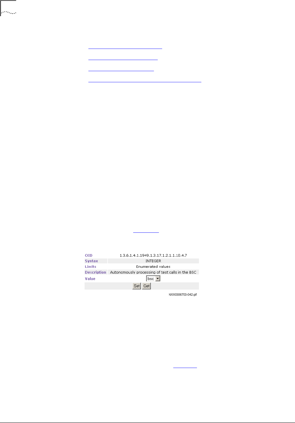
96
Chapter 7: Installation Verification
MovingMedia™ 2000 iCell All IP Radio Access Network Macro Pole Mount BTS
Part Number D01309
Installation and Initial Configuration Guide
July 2007
Loopback Testing
This section includes:
■
Configuring BSC Loopback
■
Configuring a Test Sector
■
Testing Voice Capability
■
Verifying Test Call Phone Set Parameters
Configuring BSC Loopback
Configure the BSC for diagnostic loopback testing. In a loopback test the BTS
sends a signal to the BSC and receives the returned signal after it passes
through the network. The sent signal is a voice call.
Loopback testing will test the integrity of the transmission network and the
inter-operability of the BTS and BSC. No MSC connection is needed for
loopback testing.
The Ethernet cable between the test client and the Ethernet switch should still
be connected.
To configure loopback parameters on the BSC:
1
Open the BSC Element Manager.
2
Click
cdma1x
,
performance
,
testCalls
and then
testCallEndPoint
.
The page shown in Figure 33 appears.
Figure 33
Test Call End Point Configuration
3
Select
bsc
from the dropdown menu and click
Set
.
4
Click
cdma1x
,
interfaces
,
ios
, and then
mscIp
.
5
Enter an IP address of
0.0.0.0
and then click
Set
.
6
Click
cdma1x
,
cdma
,
cdmaSystemInfo
.
7
Configure the parameters listed in Table 24.

Verifying BSS Connectivity
97
Part Number D01309
MovingMedia™ 2000 iCell All IP Radio Access Network Macro Pole Mount BTS
July 2007
Installation and Initial Configuration Guide
8
Keep the BSC Element Manager open.
To configure loopback parameters on the BTS:
1
Open the BTS Element Manager.
2
Click
cdma1x
,
cdma
,
cdmaSectorInfo
and then
sectorInfoTable
.
3
Click the value next to s
ectorCdmaFreq
for the sector being tested, enter a
CDMA frequency, and then click
Set
.
4
Keep the BTS Element Manager open.
Configuring a Test Sector
Test a single sector in the BTS by locking the other BTS sectors. All BTS sectors
should currently be unlocked.
To configure a test sector:
1
Open the BTS Element Manager, if not already connected.
2
Click
cdma1x
,
cdma
,
cdmaSectorInfo
, and then
sectorInfoTable
.
3
Lock the sectors not being tested.
Testing Voice Capability
Completing a voice call will test the loopback. Before a voice call can be
completed, the BSC and BTS must be configured for loopback, the mobile and
test client must be connected, and the phone set software must be installed and
configured with the site-specific configuration values.
To test voice capability:
1
Dial any number of digits on the mobile and then press
Send
.
2
Speak into the mobile, and confirm that your voice is audible.
Table 24
BSC Loopback Parameters
Parameter Description
sid System Identification
nid Network Identification
mcc Mobile Country Code
Table 25
BTS Loopback Parameters
Parameter Description
sid System Identification
nid Network Identification
Sector CDMA FREQ Frequency assignment
Sector EXT CDMA FREQ Extended frequency assignment

98
Chapter 7: Installation Verification
MovingMedia™ 2000 iCell All IP Radio Access Network Macro Pole Mount BTS
Part Number D01309
Installation and Initial Configuration Guide
July 2007
3
Terminate the call.
Verifying Test Call Phone Set Parameters
Verify the loopback test call parameters in the BSC using the BSC Element
Manager.
To verify test call phone set parameters:
1
Connect to the BSC Element Manager.
2
Click
cdma1x
,
performance
,
testCalls
, and then
testCallInfoTable
.
The
testCallInfoTable
displays details about test calls received by the BSC.
3
Confirm that a test call exists with the parameter values shown in Table 26.
4
Keep the BSC Element Manager open.
Table 26
Successful Test Call Parameter Values
Parameter Value
testCallImsi IMSI of the mobile used in loopback test call.
testCallServiceOption
evrcEchoSo3
testCallActivation
activeTestCall
testCallStatus
testCallActive
testCallOrigination
mobileOriginated
testCallMuxOption
1
testCallTxRate
fullRate

Part Number D01309
MovingMedia™ 2000 iCell All IP Radio Access Network Macro Pole Mount BTS
July 2007
Installation and Initial Configuration Guide
8
N
ETWORK
I
NTEGRATION
About This Chapter
This chapter describes network integration for the Macro Pole Mount BTS.
This chapter includes:
■
Core Network Integration
■
Making Test Calls
■
Provisioning Additional BTS
■
CDMA2000 Parameter Configuration
Core Network
Integration
This section includes:
■
About Core Network Integration
■
MSC Integration
■
MSC Integration Verification
■
PDSN Integration
About Core Network
Integration
The Access Network (Macro Pole Mount BTS) needs access to the Core
Network (MSC, PDSN) to provide meaningful services, such as voice and data
services.
Figure 34 shows the relationship between the Access Network and the Core
Network.
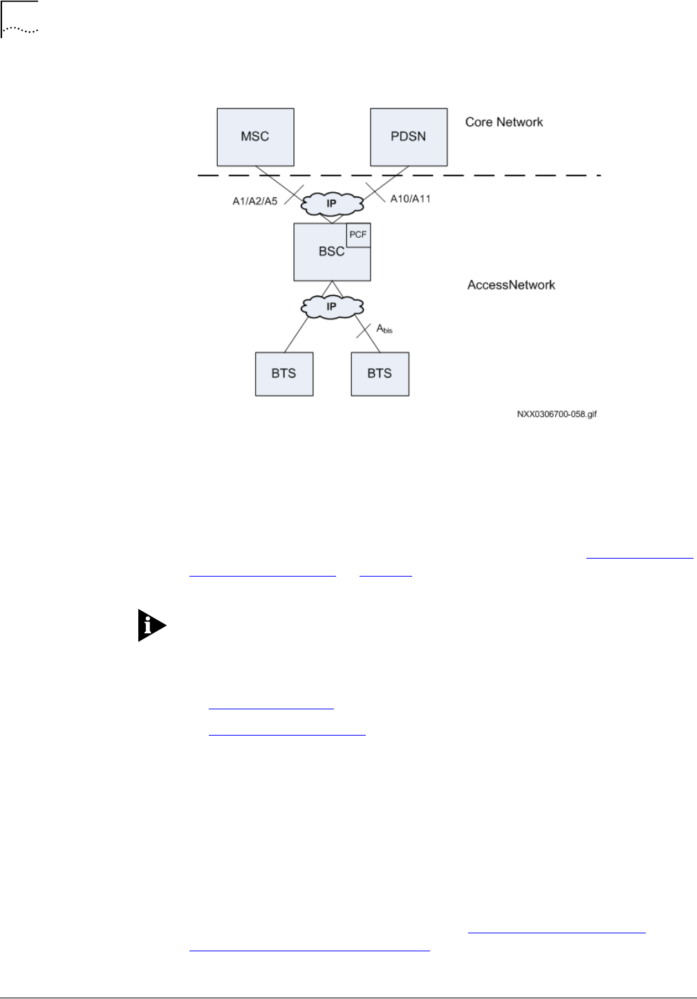
100
Chapter 8: Network Integration
MovingMedia™ 2000 iCell All IP Radio Access Network Macro Pole Mount BTS
Part Number D01309
Installation and Initial Configuration Guide
July 2007
Figure 34
Access Network and Core Network
The connection to both the MSC and PDSN is through a private IP network. The
MSC and PDSN do not need to be reachable to provision the BSC with the Core
Network connection details, but they must be reachable to perform any
integration testing and to provide services.
The private IP network should already be established (refer to Existing Core IP
Network Requirements on page 28).
Integrate the BSS into the Core Network during periods of low user traffic.
MSC Integration
This section includes:
■
Connecting to MSC
■
Checking Service Status
Connecting to MSC
The BSS needs to be connected to the MSC private IP network.
To connect to the MSC:
1
Connect the Ethernet cable-end from the MSC private IP network to the
Ethernet switch on the Macro Pole Mount BTS.
2
Telnet to the MSC.
Use the connection information gathered in Core Network IP Addresses and
Password and Username Assignment.

Core Network Integration
101
Part Number D01309
MovingMedia™ 2000 iCell All IP Radio Access Network Macro Pole Mount BTS
July 2007
Installation and Initial Configuration Guide
3
The MSC prompt (
msc >
) should be available.
Keep the
telnet
session open.
Checking Service Status
1
Use the Command Line Interface (CLI) on the MSC to check the MSC service
status with the following commands:
■
meg_dump
■
meg_res_dump
■
vsm_dump
■
csi_dump
These commands can be intensive users of MSC resources. The following
procedure should be done only with the knowledge of MSC Administrator and
preferably during low traffic periods.
To check service status:
1
Check the BSC is in service.
msc >
meg_dump -l
Confirm that the
SVC_STATE
for the BSC shows
INS
, as shown in
bold
in
Example: meg_dump Output.
2
Check Media Gateway resources.
msc >
meg_res_dump -C
Confirm that the
state
of the BSC (treated as a Gateway by the MSC and
identified by the BSC IP address) shows
INS
, as shown in
bold
in Example:
meg_res_dump Output.
3
Check the VSM subsystem.
msc >
vsm_dump
Confirm that the Virtual Switch Machine (VSM) dump shows ports
1000 -1004
as
INSERVICE
, as shown in
bold
in Example: vsm_dump Output.
4
Check the CSI subsystem.
msc >
csi_dump

102
Chapter 8: Network Integration
MovingMedia™ 2000 iCell All IP Radio Access Network Macro Pole Mount BTS
Part Number D01309
Installation and Initial Configuration Guide
July 2007
Confirm that Call Processing (CSI) dump shows
SSN inservice=TRUE IN
SYNC with BSC
, as shown in
bold
in Example: csi_dump Output.
Example: meg_dump Output
msc > meg_dump -l
ID GATEWAY_NAME SVC_STATE AUDIT_REPLIED GATEWAY_SYNCED AUD_TID
== ============ ========= ============= ============== ==============================
1 bsc1 INS 1 1 7506
2 mg1 INS 1 1 7507
Example: meg_res_dump Output
msc > meg_res_dump -C
MEG MGCP RESOURCE TABLE
res_id port gwid call_id state term cp_state
====== ===== ==== ======= ===== ========================== ==========
0 1000 1 0 INS 1@10.10.1.10 IDLE
1 1001 1 0 INS 2@10.10.1.10 IDLE
2 1002 1 0 INS 3@10.10.1.10 IDLE
3 1003 1 0 INS 4@10.10.1.10 IDLE
4 1004 1 0 INS 5@10.10.1.10 IDLE
...
25 1025 1 0 INS 26@10.10.1.10 IDLE
26 1026 1 0 INS 27@10.10.1.10 IDLE
27 1027 1 0 INS 28@10.10.1.10 IDLE
28 1028 1 0 INS 29@10.10.1.10 IDLE
29 1029 1 0 INS 30@10.10.1.10 IDLE
...
72 3019 2 0 INS ds/tr0/20@sprmg1 IDLE
73 3020 2 0 INS ds/tr0/21@sprmg1 IDLE
74 3021 2 0 INS ds/tr0/22@sprmg1 IDLE
75 3022 2 0 INS ds/tr0/23@sprmg1 IDLE
*** Total number of MGCP resource is 106 ***

Core Network Integration
103
Part Number D01309
MovingMedia™ 2000 iCell All IP Radio Access Network Macro Pole Mount BTS
July 2007
Installation and Initial Configuration Guide
If all of the MSC diagnostics show the BSC to be 'in service,' keep the MSC
Telnet connection and go to MSC Integration Verification.
MSC Integration
Verification
This section includes:
■
Checking Mobile Registration in the VLR
Checking Mobile Registration in the VLR
The VLR is a logical Network Element in the wireless Core Network, and is
integrated into the MSC. Mobiles that attempt to register in the network will
generate a query to the VLR. Use a mobile to confirm that it can register in the
network.
All of the BTS sectors were unlocked when the BTS was powered on (refer to
Bringing the Macro Pole Mount BTS into Service on page 71). The sector where
the mobile is located should remain unlocked, but the other sectors should be
locked.
The registration of the mobile in the VLR is checked using the Command Line
Interface (CLI) on the MSC. The following commands are used:
■
vlr_dump
Example: vsm_dump Output
msc > vsm_dump
Port CP State Service State Media State Ans Feat Group
====== =============== ============= =========== === ==== =====
1000 NULL INSERVICE INS 0 1 1
1001 NULL INSERVICE INS 0 0 1
1002 NULL INSERVICE INS 0 5 1
1003 NULL INSERVICE INS 0 1 1
1004 NULL INSERVICE INS 0 0 1
...
3000 NULL INSERVICE INS 0 5 3
3001 NULL INSERVICE INS 0 0 3
3002 NULL INSERVICE INS 0 0 3
3003 NULL INSERVICE INS 0 0 3
3004 NULL INSERVICE INS 0 0 3
Example: csi_dump Output
msc > csi_dump –Z
(1) BSC=1 default_lac=1 SSN inservice=TRUE IN SYNC with BSC
AIF_codec=IOS4 AIF_msgflow=IOS AIR_type=IS95
srvc_option=3 speech_type=8kb Enhanced
msc_idx=1 sms_page_max=80
SCCP Type=GAP (hostname=bsc1) (qos.ret_on_err=NONE)
usap=1 psap=1 bound=TRUE
DAD ANSI, route using SSN, address indicator is NATL
SSN: 252 PC: 000.000.000
Global Title is not present.
SAD ANSI, route using SSN, address indicator is NATL
SSN: 252 PC: 000.000.001
Global Title is not present.

104
Chapter 8: Network Integration
MovingMedia™ 2000 iCell All IP Radio Access Network Macro Pole Mount BTS
Part Number D01309
Installation and Initial Configuration Guide
July 2007
To check mobile registration in the VLR:
1
Open the BTS Element Manager.
2
Lock the 2 non-test BTS sectors.
Refer to BTS Sector Table on page 77.
3
Power on the test mobile.
4
Check if the mobile is registered in the VLR.
msc >
vlr_dump -s
Confirm that MIN, IMSI, or ESN is displayed in the dump, as shown in
bold
in
Example: vlr_dump Output.
5
If the MSC is handling traffic and the VLR dump output is verbose then search
for the mobile identity.
msc >
vlr_dump -s | grep <MIN | IMSI | ESN search string>
Where
<MIN | IMSI | ESN search string>
is the MIN, IMSI, or ESN of
the test mobile.
If the Core Network has a PDSN and the BSC was configured for a PDSN, go to
PDSN Integration on page 105.
Otherwise, go to Making Test Calls on page 106 to begin making test calls to
verify the network functionality.

Core Network Integration
105
Part Number D01309
MovingMedia™ 2000 iCell All IP Radio Access Network Macro Pole Mount BTS
July 2007
Installation and Initial Configuration Guide
PDSN Integration
This section includes:
■
Connecting to the PDSN
Connecting to the PDSN
The BSS must be connected to the PDSN private IP network.
Example: vlr_dump Output
msc > vlr_dump -s
VISITOR LOCATION REGISTER
=========================================================
MIN=7191234524 IMSI=XXXX ESN=0xFEE331E4
CARR_D= DEST_D=000000000000000
MDN=464524 PIN= VMB=000000000000000
HAVE_PROFILE=TRUE AUTH_DENY=0 OIND=7 GROUP=0 TERM_RESTRICT=2
CFU=2 CFB=2 CFNA=2 CW=2 TWC=2 CD=3 CNIP1=1 CNIR=1 CNIR_OVERRIDE=1
ORIG_TRIG=0x00000000 MSG_WAIT_TYPE=0x00 MSG_WAIT_CNT=255 255 255 255 255 255
DMH_BILL_D=000000000000000
TAL_DEST=(TYP=0 ADDR=0 0.0.0.0.0.0.0.0.0.0.0.0.0.0.0)
TAL_TRIGS=0 0 0 0 0 0 0 0 0 0 0 0 0 0 0 0 ...
HO=0 VMW=0 status=0x0 party=0 lai=1 expiry=INDEFINITE
ACTV=TRUE ACCESS=Fri Jun 10 02:27:12 2005
SMS_ADDR nature=49 plan=13 encoding=3 bcd_digit=4 addr=0x35080000
SMS_ORIG_REST default=0 direct=0 force_message_center=0
SMS_TERM_REST default=0 reverse_charges=0
SMSDPF=0
MIN=6191234511 IMSI= ESN=0xFE3A2FD3
CARR_D= DEST_D=000000000000000
MDN=464511 PIN= VMB=000000000000000
HAVE_PROFILE=TRUE AUTH_DENY=0 OIND=7 GROUP=0 TERM_RESTRICT=2
CFU=2 CFB=2 CFNA=2 CW=2 TWC=2 CD=3 CNIP1=1 CNIR=1 CNIR_OVERRIDE=1
ORIG_TRIG=0x00000000 MSG_WAIT_TYPE=0x00 MSG_WAIT_CNT=255 255 255 255 255 255
DMH_BILL_D=000000000000000
TAL_DEST=(TYP=0 ADDR=0 0.0.0.0.0.0.0.0.0.0.0.0.0.0.0)
TAL_TRIGS=0 0 0 0 0 0 0 0 0 0 0 0 0 0 0 0 ...
HO=0 VMW=0 status=0x0 party=0 lai=1 expiry=INDEFINITE
ACTV=TRUE ACCESS=Fri Jun 10 02:26:56 2005
SMS_ADDR nature=49 plan=13 encoding=3 bcd_digit=4 addr=0x35080000
SMS_ORIG_REST default=0 direct=0 force_message_center=0
SMS_TERM_REST default=0 reverse_charges=0
SMSDPF=0

106
Chapter 8: Network Integration
MovingMedia™ 2000 iCell All IP Radio Access Network Macro Pole Mount BTS
Part Number D01309
Installation and Initial Configuration Guide
July 2007
To connect to the PDSN:
1
Connect the Ethernet cable end from the PDSN private IP network to the
Ethernet switch on the Macro Pole Mount BTS.
2
Telnet to the PDSN.
Use the connection information gathered in Core Network IP Addresses and
Password and Username Assignment.
Making Test Calls
This section includes:
■
Before Making Test Calls
■
Making Voice Test Calls
■
Making Data Test Calls
Before Making Test Calls
A voice test call and a data test call (if applicable) are made to verify the
integration. The 2 mobiles must have a subscriber profile in the HLR (voice
calls) and the AAA (data calls) for the test calls to succeed.
The Operator (NOC personnel) should have provisioned the test mobiles in the
respective HLR and/or PDSN as part of the prerequisites phase (refer to
Recommended Test Equipment on page 25).
This guide does not describe how to provision a subscriber in the HLR or in the
AAA server.
Making Voice Test Calls
A mobile-to-mobile call tests the MSC part of Core Network integration.
To make a voice test call:
1
Power on both test mobiles.
2
Confirm that a call can be originated and terminated from each test mobile to the
other.
Making Data Test Calls
A data call tests the PDSN part of Core Network integration. A data call can be
as simple as accessing any Web page on the Internet. The Audiovox test phone
(any many other CDMA2000 phones) has a quick Web access button.
To make a data test call:
1
Select a test mobile and press the quick Web access button.
2
A Web page should be loaded in the phone.
If the voice and data (if applicable) test calls are successful, then the installation,
configuration, and Core Network integration of the Macro Pole Mount BTS is
complete.

Provisioning Additional BTS
107
Part Number D01309
MovingMedia™ 2000 iCell All IP Radio Access Network Macro Pole Mount BTS
July 2007
Installation and Initial Configuration Guide
If additional BTS need to be provisioned in the Macro Pole Mount BTS go to
Provisioning Additional BTS.
Provisioning
Additional BTS
This section includes:
■
About Additional BTS
■
Provisioning Additional BTS
About Additional BTS
The initial Macro Pole Mount BTS configuration has a single BTS that supports
one FA. Other configurations add additional BTS units for increased capacity.
This guide does not describe how to add physical Macro Pole Mount BTS and
supporting hardware to an existing Macro Pole Mount BTS configuration
(hardware expansion). Please refer to the Macro Pole Mount BTS Operations
and Maintenance Guide for hardware upgrade procedures.
The MSC Server will be provisioned for the particular Macro Pole Mount BTS
configuration.
Provisioning Additional BTS describes how to provision additional BTS after the
initial BSC and BTS have been configured. Provision each additional BTS in
turn, bringing each one into service before adding the next BTS.
Provisioning Additional
BTS
This section includes:
■
Provisioning BTS in MSC
■
Configuring Additional BTS
■
Reloading Additional BTS
■
Verifying BSS Operational State
■
Performing Loopback Testing
■
Making Test Calls
Provisioning BTS in MSC
The additional BTS need to be provisioned in the MSC. This guide does not
describe how to provision the MSC. Refer to 'Adding and Removing Base
Station Subsystems' in the MSC Server Provisioning Guide (D00620) for details
on how to provision additional BTS in the MSC.
Configuring Additional BTS
Configure each additional BTS with the same configuration as the first BTS,
except for the following:
1
Amend the BTS1-specific names and addresses for the new BTS.
2
Use the first (initial) BTS as the SNTP server for all additional BTS.

108
Chapter 8: Network Integration
MovingMedia™ 2000 iCell All IP Radio Access Network Macro Pole Mount BTS
Part Number D01309
Installation and Initial Configuration Guide
July 2007
Follow all of the procedures in Configure the BSC on page 89 to configure each
additional BTS.
Reloading Additional BTS
Reload each BTS after it is configured.
Verifying BSS Operational State
1
Verify the operational state of the BSC and newly provisioned BTS. Refer to
Configure the BTS on page 89.
2
Check the operational state of the BSC and all BTS again after all of the BTS
have been provisioned.
Performing Loopback Testing
Perform loopback testing on the new each new BTS (the BSC will also have to
be configured for the loopback test).
Making Test Calls
Make test calls from each a sector in each new BTS to test network functionality.
No further testing or verification of new BTS is required.
CDMA2000 Parameter
Configuration
This section includes:
■
About Factory CDMA2000 Parameter Settings
■
Configuring CDMA2000 Parameters
About Factory
CDMA2000 Parameter
Settings
The CDMA2000 Access Network is configured using CDMA2000 parameters.
Some parameters are configured on the BSC and some are configured on the
BTS. The Macro Pole Mount BTS comes with a sample CDMA2000 parameter
configuration (
bsc1.cfg
for the BSC and
bts1.cfg
for the BTS). Additional
sample configuration files are also provided for multiple FA configurations.
The factory default CDMA2000 configuration was deployed during initial
configuration. (Refer to Configure the BSC and Configure the BTS). The
installation verification and Core Network integration was performed using
factory default CDMA2000 parameter values.
Configuring CDMA2000
Parameters
CDMA2000 parameters are configured using the BSC and BTS Element
Managers. The parameters values are specific for each site, and the Network
Planning document (site engineering specification) will provide the parameters
values for the BSC and BTS for a given site.
This document does not describe how to configure the CDMA2000 parameters
for a Macro Pole Mount BTS site. Refer to the iCell BSS Parameter


110
Chapter 8: Network Integration
MovingMedia™ 2000 iCell All IP Radio Access Network Macro Pole Mount BTS
Part Number D01309
Installation and Initial Configuration Guide
July 2007

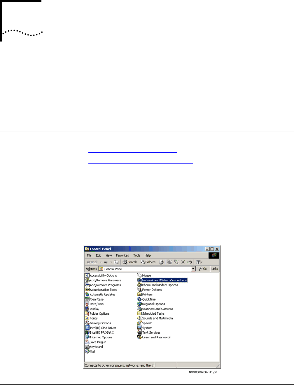
Part Number D01309
MovingMedia™
2000
iCell All IP Radio Access Network Macro Pole Mount BTS
July 2007
Installation and Initial Configuration Guide
A
T
EST
C
LIENT
C
ONFIGURATION
About This Appendix
This appendix includes:
n
Configuring Test Client
n
Setting Up Installation Directory
n
Installing and Configuring Other Software
n
Connecting Test Client to BSS Components
Configuring Test
Client
This section includes:
n
Configure Test Client IP Address
n
Configuring Serial Connection Settings
Configure Test Client IP
Address
The test client (usually a laptop PC) must be on the same subnet as the Network
Elements that are being configured.
To configure the IP address:
1
Click
Start
, and select
Settings
, and then click
Control Panel
.
The window shown in Figure 35 appears.
Figure 35
Control Panel
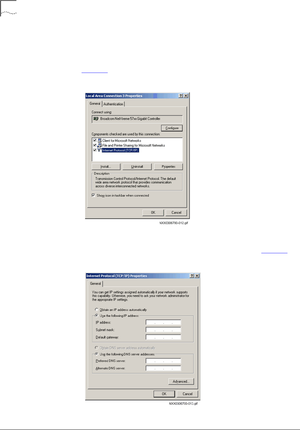
116
A
PPENDIX
A: T
EST
C
LIENT
C
ONFIGURATION
MovingMedia™
2000
iCell All IP Radio Access Network Macro Pole Mount BTS
Part Number D01309
Installation and Initial Configuration Guide
July 2007
2
Double-click
Network and Dial-up Connections
.
3
In the Network and Dial-up Connections window, right-click
Local Area
Connection
and click
Properties
.
The
Local Area Connection Properties
dialog box appears, as shown in
Figure 36.
Figure 36
LAN Connection Properties
4
Select
Internet Protocol (TCP/IP)
and click
Properties
.
The
Internet Protocol (TCP/IP)
dialog box appears, as shown in Figure 37.
Figure 37
TCP/IP Properties
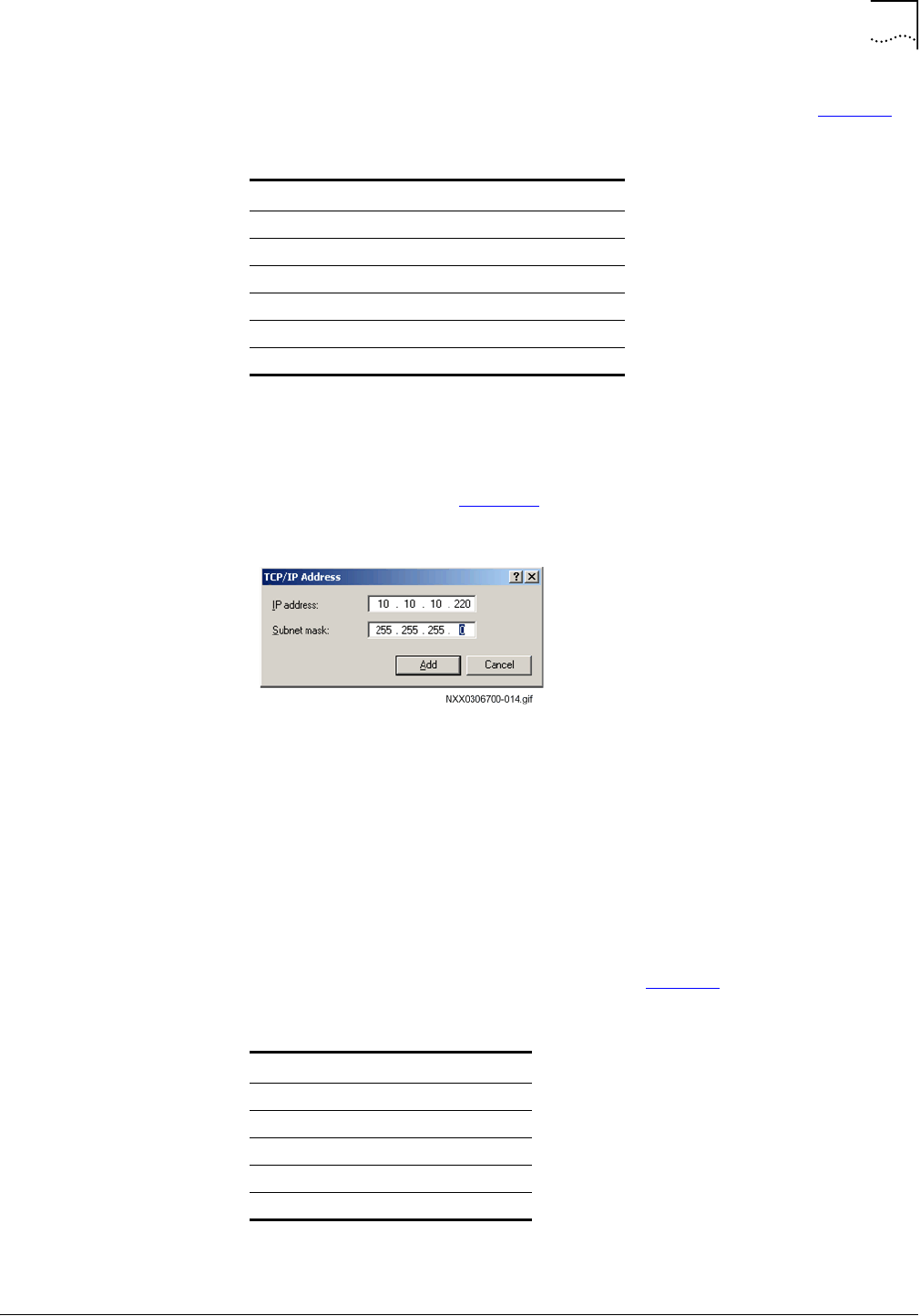
Configuring Test Client
117
Part Number D01309
MovingMedia™
2000
iCell All IP Radio Access Network Macro Pole Mount BTS
July 2007
Installation and Initial Configuration Guide
5
Select
Use the following IP address
and enter the values listed in Table 27.
6
In the
Internet Protocol (TCP/IP)
dialog box, click
Advanced
.
The
Advanced TCP/IP Settings
dialog box appears.
7
In the
IP addresses
pane, click
Add
.
The dialog box shown in Figure 38 appears.
Figure 38
Secondary IP Address
8
Add the secondary IP address and click
Add
.
9
Exit back to
Network and Dial-up Connections
and then close it.
The test client now has the IP addresses required to connect to the BSC, BTS,
and Ethernet switch.
Configuring Serial
Connection Settings
Portions of the installation and configuration process require a serial connection.
Use a serial client to create a serial connection
1
Configure the COM1 port settings according to Table 28.
Table 27
Test Client IP Addressing
Parameter Value
IP address 1
Subnet mask 1
Default gateway 1
IP address 2
Subnet mask 2
Default gateway 2
Table 28
COM1 Port Configuration Values
Parameter Value
Bits per second 38400
Data bits 8
Parity None
Stop bits 1
Flow control None

118
A
PPENDIX
A: T
EST
C
LIENT
C
ONFIGURATION
MovingMedia™
2000
iCell All IP Radio Access Network Macro Pole Mount BTS
Part Number D01309
Installation and Initial Configuration Guide
July 2007
This serial connection can be used for the elements listed in Table 29.
Setting Up Installation
Directory
This section includes:
n
About Tools CD ROM
n
Setting up Install Directory
About Tools CD ROM
The tools CD ROM contains all of the software tools needed to install, configure,
and test the Macro Pole Mount BTS. Refer to Tools CD ROM on page 27 for
more information on the tools CD ROM.
Setting up Install
Directory
Setup an installation directory on the test client.
To setup install directory:
1
Create a new
\install
directory under the root directory of the
C:
drive.
2
Insert the tools CD ROM into the test client.
3
Copy the contents of the tools CD ROM to the
C:\install
directory.
4
Remove the tools CD ROM from the test client and store it safely.
Installation, configuration, and verification procedures will reference this install
path.
Installing and
Configuring Other
Software
This section includes:
n
SSH Telnet Client
SSH Telnet Client
This section includes:
n
Installing SSH Telnet Client
n
Configuring SSH Telnet Client
Installing SSH Telnet Client
PuTTY is used as a Telnet client to access the BSC, and BTS. PuTTY is a free
implementation of Telnet and SSH for Win32 and Unix platforms, and includes
an xterm terminal emulator.
Table 29
Serial Connection Baud Rates
Network Element Bits per Second (Baud Rate)
Ethernet Switch 38400
BSC 38400
BTS 38400
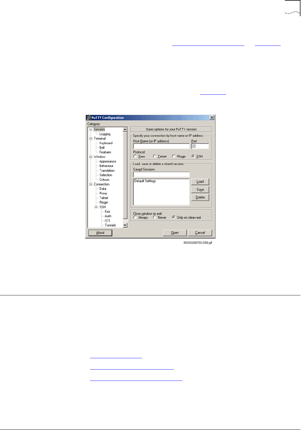
Connecting Test Client to BSS Components
119
Part Number D01309
MovingMedia™
2000
iCell All IP Radio Access Network Macro Pole Mount BTS
July 2007
Installation and Initial Configuration Guide
The following procedure assumes the contents of the tools CD ROM was copied
to the local drive as described in Setting up Install Directory on page 118.
To Install SSH Telnet client:
1
Navigate to
C:\install\bss\support\telnet
.
2
Execute
putty.exe
.
The PuTTy application opens, as shown in Figure 39
Figure 39
PuTTY Application
Configuring SSH Telnet Client
No additional configuration of PuTTY is required. Further configuration is
optional. Click
About
>
Visit Web Site
to view the documentation.
Connecting Test
Client to BSS
Components
A connection to BSS components is required throughout various installation,
configuration, and verification procedures. This section provides the details for
how to connect to the BSS components. Both a serial connection and Ethernet
connection are described for each BSS component.
This section includes:
n
Serial Connections
n
Connecting to Ethernet Switch
n
Connecting to Element Managers
Serial Connections
A serial connection can be used for most installation, configuration, and
verification activities. A serial connection is used to connect with the Ethernet
switch, BSC, and BTS.
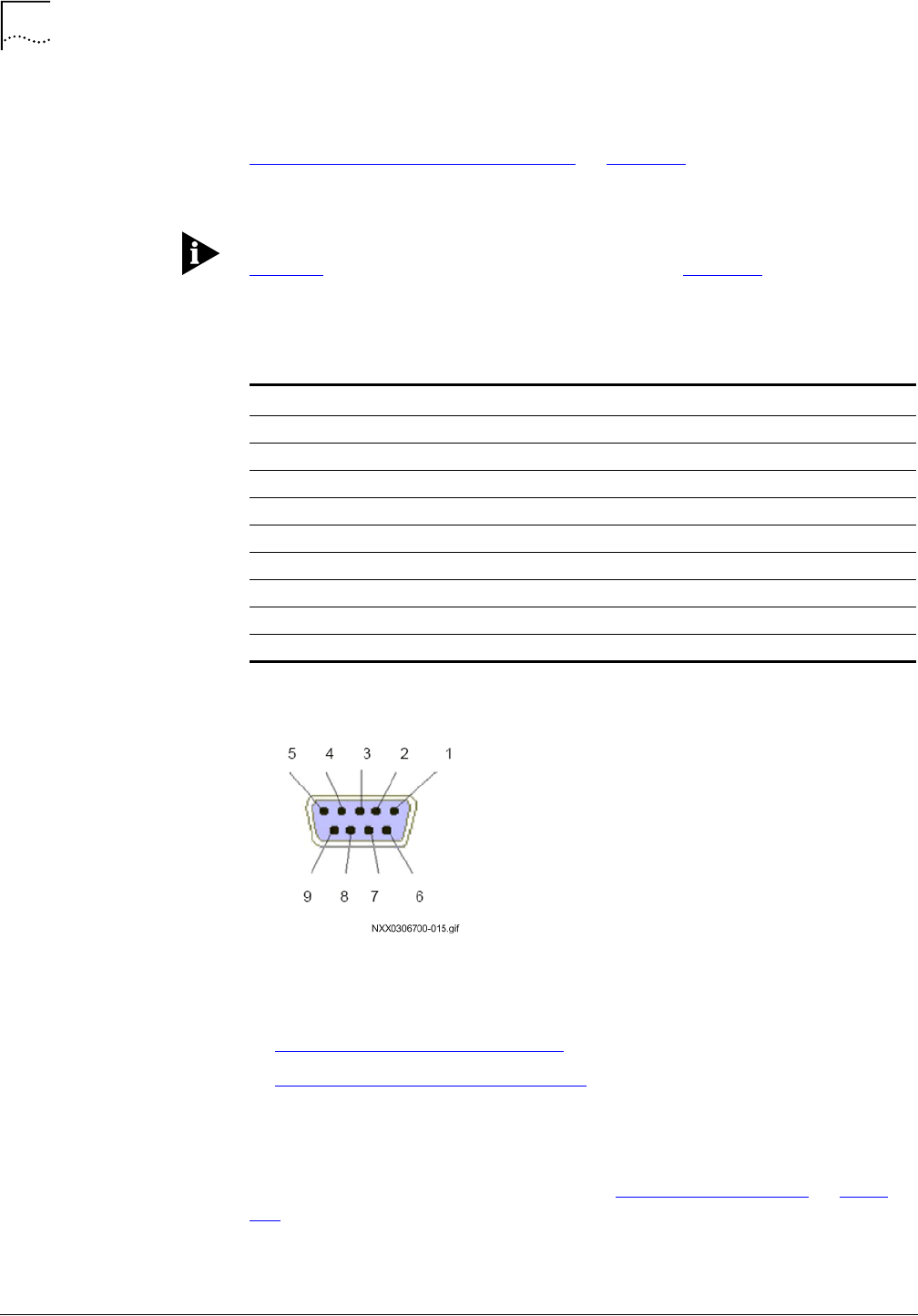
120
A
PPENDIX
A: T
EST
C
LIENT
C
ONFIGURATION
MovingMedia™
2000
iCell All IP Radio Access Network Macro Pole Mount BTS
Part Number D01309
Installation and Initial Configuration Guide
July 2007
A standard serial cable with DB-9 connectors is used to connect the test client
and BSS components. HyperTerminal is used as the serial client (refer to
Configuring Serial Connection Settings on page 117 for details on configuring
HyperTerminal).
Serial Cable
Table 30 shows the pinouts for the serial cable and Figure 40 shows the DCE
pinout on the switch.
Figure 40
DCE Pinout on Switch (Female End)
Connecting to Ethernet
Switch
This section includes:
n
Ethernet Switch Serial Connection
n
Ethernet Switch Ethernet Connection
Ethernet Switch Serial Connection
The test client should already be configured for both serial and Ethernet
connections to the Ethernet switch (refer to Configuring Test Client on page
115).
Table 30
Serial Cable Pinouts
DCE DB-9 (Male) End Pin DTE DB-9 (Female) End
Received Line Signal Detect (DCD) 1Received Line Signal Detect (DCD)
Received Data (RXD) 2Transmitted Data (TXD)
Transmitted Data (TXD) 3Received Data (RXD)
DTE Ready (DTR) 4DTE Ready (DTR)
Signal Ground (SIG GND) 5Signal Ground (SIG GND)
DCE Ready (DSR) 6DCE Ready (DSR)
Request to Send (RTS) 7Request to Send (RTS)
Clear to Send (CTS) 8Clear to Send (CTS)
Ring Indicator (RI) 9Ring Indicator (RI)
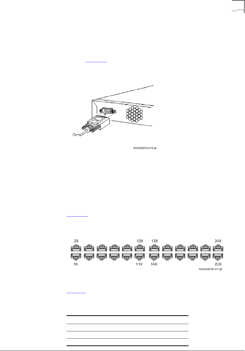
Connecting Test Client to BSS Components
121
Part Number D01309
MovingMedia™
2000
iCell All IP Radio Access Network Macro Pole Mount BTS
July 2007
Installation and Initial Configuration Guide
To connect switch and test client serial cable:
1
Connect the male end of the DB-9 serial cable to the test client.
2
Connect the female end of the serial cable to the console port at the rear of the
Ethernet switch.
Refer to Figure 41 for the location of the serial port.
Figure 41
Switch Serial Port Location
3
Open HyperTerminal and press
Enter
a few times to get a prompt.
Ethernet Switch Ethernet Connection
An Ethernet cable is used to connect the test client and the switch. A standard
cross-over Ethernet cable with 2 RJ-45 connector ends is required. The cable
should be ~3M, depending on the site requirements.
Figure 42 shows the port numbering on the Ethernet switch.
Figure 42
Ethernet Switch Port Numbering
Table 31 lists the ports assignments on the Ethernet switch.
Table 31
Ethernet Switch Port Assignments
Switch Port Network Element
1X BSS
3X BTS
2X Reversed

122
A
PPENDIX
A: T
EST
C
LIENT
C
ONFIGURATION
MovingMedia™
2000
iCell All IP Radio Access Network Macro Pole Mount BTS
Part Number D01309
Installation and Initial Configuration Guide
July 2007
To connect test client and switch:
1
Connect one end of the Ethernet cable to the test client.
2
Connect the other end to port 13X on the Ethernet switch.
Any open port will work.
IP Addressing Information
The Ethernet switch is configured as part of an overall IP network plan. Have the
switch IP address information available before starting to configure the switch.
The required IP information, and the factory defaults are listed in Table 32.
Connecting to Element
Managers
A connection to the BSC and BTS Element Managers is required throughout the
installation, initial configuration, and installation verification phases. The
Element Managers are browser-based HTTP interfaces.
The Element Managers present the Management information Base (MIB) for the
BSC and BTS in a graphical format. Click the links to browse the MIB and GET
and SET parameters values.
The Element Managers can be accessed after the Macro Pole Mount BTS has
been powered on.
This section includes:
n
Connecting to BSC Element Manager
n
Connecting to BTS Element Manager
Table 32
Switch IP Address Information and Defaults
Site Specific Switch IP information Factory Default
BTS 10.10.10.20
BSC 10.10.10.10
Switch IP Address 10.10.10.2
Subnet Mask 255.255.255.0
Default Gateway 10.10.10.1
Switch Password tel os
Connecting Test Client to BSS Components
123
Part Number D01309
MovingMedia™
2000
iCell All IP Radio Access Network Macro Pole Mount BTS
July 2007
Installation and Initial Configuration Guide
Connecting to BSC Element Manager
The BSC Element Manager is used to perform the Configuration Management
tasks on the BSC. The configuration parameters for the BSC are under the
cdma1x root.
To connect to BSC Element Manager:
1
Open a browser window and load the IP address of the BSC.
The BSC Element Manager interface is shown in Figure 43.
Figure 43
BSC Element Manager Interface
2
Click the links to navigate through the interface.
Connecting to BTS Element Manager
The BTS Element Manager is used to perform the Configuration Management
tasks on the BTS. The configuration parameters for the BTS are under the
cdma1x root.
To connect to BTS Element Manager:
1
Open a browser window and load the IP address of the BSC.
The BSC Element Manager interface is shown in Figure 44.

124
A
PPENDIX
A: T
EST
C
LIENT
C
ONFIGURATION
MovingMedia™
2000
iCell All IP Radio Access Network Macro Pole Mount BTS
Part Number D01309
Installation and Initial Configuration Guide
July 2007
Figure 44
BTS Element Manager Interface
2
Click the links to navigate through the interface.

China
No. 368 Liuhe Road,
Hi-Tech Industry Development Zone,
Binjiang, Hangzhou 310053, PRC
+86-571-81920000
India
805 Signature Towers II,
South City I
Gurgaon,
Haryana 122001, India
+91 124 5166100
Japan
Shiba Koen Parktower 9F/10F
2-11-1 Shiba-koen, Minato-ku
Tokyo 105-0011 JAPAN
+81-3-6430-8600
Europe
Campus Kronberg 7
Kronberg, 61476
Germany
+49 (617) 3946-3460
Latin America
2801 SW 149th Ave
Suite 100
Miramar, FL 33027, USA
954-447-3077
UTStarcom, Inc. USA
1275 Harbor Bay Parkway Alameda, CA 94502, USA
Tel. 510-864-8800 Fax. 510-864-8802
About UTStarcom www.utstar.com
Headquartered in the United States with sales, support, and manufacturing facilities worldwide, UTStarcom designs, manufactures, sells, and installs an
integrated suite of wireless and wireline access network and switching systems. UTStarcom’s complete suite of network equipment gives telecommunication
service providers the means to cost-effectively provide efficient and scalable voice, data, and Internet services around the globe.
Copyright © 2005 UTStarcom, the UTStarcom logo, !-Volution, AIRSTAR, AN-2000, AN-FTTB, CommWorks, the CommWorks logo, iAN, iCell, Internode,
Intranode, iPATH, ISP, MovingMedia, mSwitch, Next Generation Network Technology. Now, NGDLC, PAS, PAS Wireless, Seamless World, Softexchange,
Sonata, Sonata Access Tandem, Sonata HLR, Sonata IP, Sonata MSC, Sonata WLL, Telos, Total Control, Unitech, WACOS, WICOPS, WLL, and Xtreme IP are
registered trademarks or trademarks of UTStarcom, Inc. and its subsidiaries.
Part Number D01309