Strattec Security 0071TR RF Hub User Manual
Strattec Security Corporation RF Hub Users Manual
Contents
- 1. Users Manual
- 2. Installation Manual
Users Manual

Installation Manual
Draft
Model: FI2-TR433UDA
1 Installation
The Radio Frequency HUB Module (RFHM) is an integrated receiver (Base Station), usually mounted on
the rear shelf of the vehicle.
2 General Description
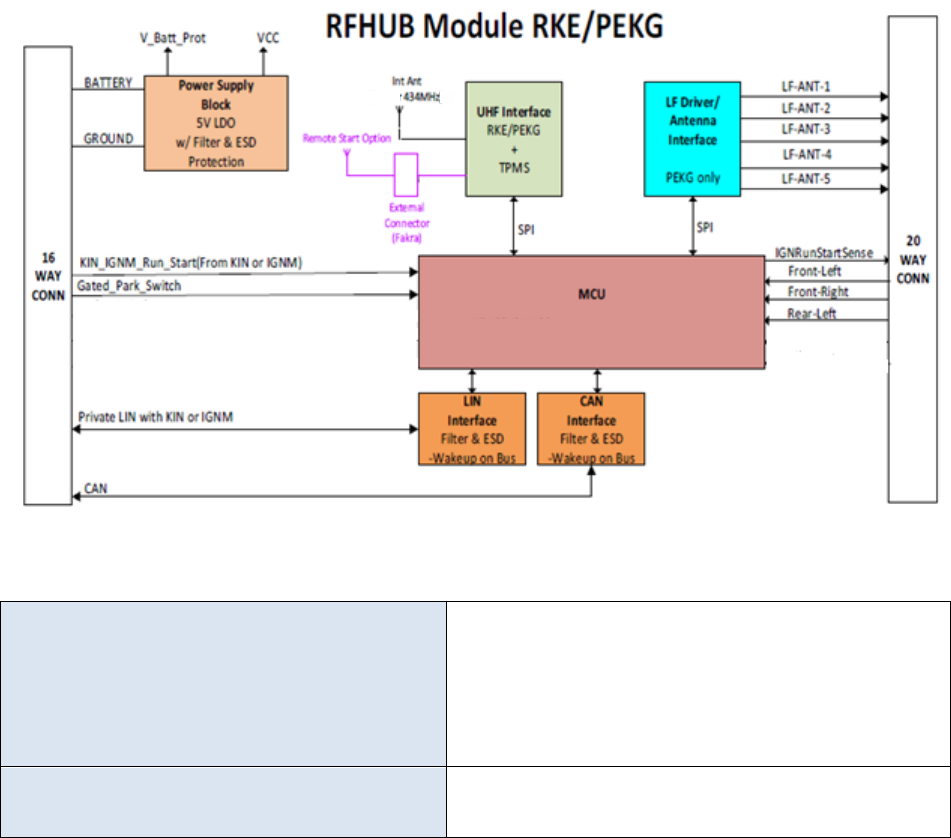
The RFHM interfaces with the Remote Keyless Entry (RKE) and FOBIK via both RF and LF and the
Immobilizer Transponder key via LF. The Radio Frequency HUB Module (RFHM) communicates with the
TPM Sensors via RF.
The Radio Frequency HUB Module (RFHM) contains the controlling logic for the Passive Entry Keyless Go
(PEKG) feature, Remote Keyless Entry (RKE) feature, and the Keyless Ignition Node (KIN) lighting where
applicable.
The Radio Frequency HUB Module (RFHM) communicates on CAN C to the rest of the vehicle modules.
The RFHM communicates to Keyless Ignition Node (KIN) via a dedicated KIN-Line.
The RFHM receives ignition states, OFF/LOCK (KEY-OUT), OFF (KEY-IN), ACC, RUN & START from the
Ignition Node Module (IGNM) and then uses that information to determine actual ignition position and
communicate that information over the CAN vehicle communication bus.
The Radio Frequency HUB Module (RFHM) also interfaces with the vehicle’s door handles, trunk/lift-gate
and multiple LF antennas for purposes of providing PEKG system functionality.
RF Hub Installation Manual
• RF Hub is mounted on cab back wall with two push pins
• Installation includes the following steps:
o Connect two vehicle side harnesses to RF Hub module
o Install RF Hub module to the cab back wall with two push pins

3 Technical and Functional Description
This is an RF Hub module (RFHM) with Keyless Go and optional Passive Entry functionality. It has an LF
driver for communication with a Fob for the PEKG function and an RF receiver for TPM, RKE and PEKG
reception from a Fob or TPM sensor (433.92MHZ or 315 MHZ depending Market). It communicates to a
Keyless Ignition Node (KIN) via a dedicated LIN bus. It also communicates to the rest of the vehicle via
the CAN bus. While the KIN performs the Immobilizer, back-up start mode to cover a dead battery, the
RFHM controls the KIN via the LIN bus and validates the key that the KIN reads. The module also has
several inputs and outputs to aid PEKG function. It reads the door handle inputs to initiate the PE
function. It also reads the KIN switch state (back-up for LIN failure). It reads the park state of the
transmission. It has several outputs. They include a HSD to control a redundant IgnRun state to the
BCM.
There are two models one with an internal antenna and one with an external output for an external
antenna. The module provides 5V to power the external antenna on the center conductor of the
external antennas coax cable.
4 Main Characteristics
Supply Voltage Range
6-16, LF drive only works down to 9V per
specification
USMin = 6V; USMax = 16V
U Typ = 13.5V
Temperature range
-40 to 85 °C
TMax = 85 °C; Tamb = 23 °C

5 Frequency Bands
RF
1. Internal Antenna (Piece of
Metal on the PCB)
2. External Antenna (Fraka
Connector)
Receiver ONLY
Center Frequency: 433.92 MHz
Accuracy ±40 kHz
Sensitivity: -105 dBm
Information Below applies just for External
Antenna
The External Antenna is being supply for the RF
HUB a 50 ohms load at 5V @ 10mA.
LF Antennas
Transmitter ONLY
125 kHz
Frequency Range: 125kHz +/- 500Hz
Maximum RF Output Power (W): NA
Modulations: ASK (OOK)
Channel Spacing: NA
Number of channels: 1
Channel bandwidth: NA
1App current into the ferrite.
Inductance @ 125kHz – 125uH
Q Factor Q > 50
Resonant Frequency > 800kHz
Operating Voltage = < 650Vpp
6 Technical Specifications
6.1 Modulations
RF (Receiver) 433.92 MHz
2.4Kbps ASK Manchester
LF (Transmitter) 125 kHz
19.2 Kbps FSK Manchester

FCC/ISED Regulatory notices
FCC ID: OHT-0071TR
IC: 5461A-0071TR
Model Name: F12-TR433UDA
Modification statement
STRATTEC SECURITY CORPORATION has not approved any changes or modifications to this device by the
user. Any changes or modifications could void the user’s authority to operate the equipment.
Or/
Changes or modifications not expressly approved by the party responsible for compliance could void the user’s
authority to operate the equipment.
Interference statement
This device complies with Part 15 of the FCC Rules and Industry Canada licence-exempt RSS standard(s).
Operation is subject to the following two conditions: (1) this device may not cause interference, and (2) this device
must accept any interference, including interference that may cause undesired operation of the device.
Le présent appareil est conforme aux CNR d'Industrie Canada applicables aux appareils radio exempts de licence.
L'exploitation est autorisée aux deux conditions suivantes : (1) l'appareil ne doit pas produire de brouillage, et (2)
l'utilisateur de l'appareil doit accepter tout brouillage radioélectrique subi, même si le brouillage est susceptible
d'en compromettre le fonctionnement.
FCC Class B digital device notice
This equipment has been tested and found to comply with the limits for a Class B digital device, pursuant to part 15 of
the FCC Rules. These limits are designed to provide reasonable protection against harmful interference in a
residential installation. This equipment generates, uses and can radiate radio frequency energy and, if not installed
and used in accordance with the instructions, may cause harmful interference to radio communications. However,
there is no guarantee that interference will not occur in a particular installation. If this equipment does cause harmful
interference to radio or television reception, which can be determined by turning the equipment off and on, the user is
encouraged to try to correct the interference by one or more of the following measures:
- Reorient or relocate the receiving antenna.
- Increase the separation between the equipment and receiver.
- Connect the equipment into an outlet on a circuit different from that to which the receiver is connected.
- Consult the dealer or an experienced radio/TV technician for help.