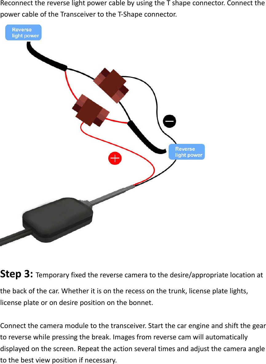
Supa Technology GA6040-RX Wireless Backup Camera User Manual GA 6040 Installation Guide

Supa Technology Co., Ltd. Wireless Backup Camera GA 6040 Installation Guide

manual

GA6040wirelessbackupcamera
Introduction:WirelessReverseCameraGA6040isdesignforvehicleownerswhichwishtoselfinstallthereversecameratotheirvehicle.3majorpartsarerequiredforinstallation:ReverseCamera:Whichinstalledoutsideatthebackofthevehicle.Transceiver:Whichconnectstothereverselight’spowercableandReverseCamera,itisresponsibletowirelesslytransferthecameraimagetothereceivingend.Receiver:Connecttothemonitor,whichdisplayimagesfromthereversecam.VideoStreamingistransferin2.4GHzISMband,usingwirelessmultimediaprocessortoovercomesdifferentinterferences,likemicrowave‐oven,andworkcoexistencewithother2.4GHzwirelessdevices,likecordlessphone,WiFi,bluetooth,wirelesskeyboardandmouse.Therobustanti‐interferencecapabilityiscontrolledbywirelessmultimediaprocessortoperformadaptivefrequencyhoppingspreadingspectrumprotocol.PowerinputforGA6040is12~24Vforthetransceiver,whichissuitableforpassengervehicleinclude,Sedan,Hatchback,Couple,4wheeldrive,MVPandSUV.Powerconvertermayrequireifyouwishtoinstallonthelargercommercialvehicle.Pleasecheckthevehiclebatteryvoltagebeforeinstallation.PackageContent:Packagesincludes:1xCameraModule1xTransceiverforconnectionwithcameramoduleandreverselight’spowercable1xReceiverforconnectiontoscreenandpower.4xpowercableconnectorCamera Module Specifications   Component and Optical   Specification Spec. Horizontal FOV    Approximately 120°  Vertical FOV  Approximately 100° Diagonal FOV  Approximately 140° F No.   2.0±5%
CMOS Sensor Size  1/4” Array Size  640x480 Optical distortion   1.0%  Lens Size    1/4”   Lens Type    4G UV resistance  Yes Anti fog coating  Yes/with Self clean   ID design Compliance  IPX6; IPX7 Storage Temperature  +75℃ ~ -20℃ Operation Humidity  90% RH Power Supply  9~12 V; From Transceiver Cable length  1800 mm Dimension  Approximately 30.2mm x 31.6mm x 30.5 mm 
StepbyStepinstallationStep1:Connectthereceivertothemonitorvia3.5mmAVoutconnector.Connectthereceiverwith5V0.5~1ampminiUSBcarcharger.Step2:Placethetransceivernearbythereverselight.Connectthepowercableofthetransceivertothepowercableofthereverselight.
ReconnectthereverselightpowercablebyusingtheTshapeconnector.ConnectthepowercableoftheTransceivertotheT‐Shapeconnector.Step3:Te mporaryfixedthereversecameratothedesire/appropriatelocationatthebackofthecar.Whetheritisontherecessonthetrunk,licenseplatelights,licenseplateorondesirepositiononthebonnet.Connectthecameramoduletothetransceiver.Startthecarengineandshiftthegeartoreversewhilepressingthebreak.Imagesfromreversecamwillautomaticallydisplayedonthescreen.Repeattheactionseveraltimesandadjustthecameraangletothebestviewpositionifnecessary.
CameraIDConnectedcamera’sVideoOutandPowerintotransceiver.Upanddownadjustment:Bybendingthemetallicfixedplateorapplydifferentthicknesslayerofdoublesidedtape.Leftandrightadjustment:Byapplydifferentlayersofdoublesidedtapeontheleft
andrightsideofthefixedmetalplate.Step4:Cablingthru:toavoidcameracabledistractappearanceofthevehicle,itisrecommendedtohidethecameracableinthefollowinglocation:Removethelicenseplatelightcoverandinsertthecameracablein.
Movethecameracablealongthecableholder.Connectthecameracabletothereceiver.Exampleofthecompleteinstallation.
Note:Ifreverselightofyourvehicleislocatedatthetrunklidyoumayfixedthetransceiverontherarebonnettominimizedthecomplexityofwiringaroundthevehicle.Warning:FederalCommunicationsCommission(FCC)Statement15.21Youarecautionedthatchangesormodificationsnotexpresslyapprovedbythepartresponsibleforcompliancecouldvoidtheuser’sauthoritytooperatetheequipment.15.105(b)ThisequipmenthasbeentestedandfoundtocomplywiththelimitsforaClassBdigitaldevice,pursuanttopart15oftheFCCrules.Theselimitsaredesignedtoprovidereasonableprotectionagainstharmfulinterferenceinaresidentialinstallation.Thisequipmentgeneratesusesandcanradiateradiofrequencyenergyand,ifnotinstalledandusedinaccordancewiththeinstructions,maycauseharmfulinterferencetoradiocommunications.However,thereisnoguaranteethatinterferencewillnotoccurinaparticularinstallation.Ifthisequipmentdoescauseharmfulinterferencetoradioortelevisionreception,whichcanbedeterminedbyturningtheequipmentoffandon,theuserisencouragedtotrytocorrecttheinterferencebyoneormoreof
thefollowingmeasures:‐Reorientorrelocatethereceivingantenna.‐Increasetheseparationbetweentheequipmentandreceiver.‐Connecttheequipmentintoanoutletonacircuitdifferentfromthattowhichthereceiverisconnected.‐Consultthedealeroranexperiencedradio/TVtechnicianforhelp.Thisdevicecomplieswithpart15oftheFCCRules.Operationissubjecttothefollowingtwoconditions:1)thisdevicemaynotcauseinterferenceand2)thisdevicemustacceptanyinterference,includinginterferencethatmaycauseundesiredoperationofthedevice. 

Navigation menu