Suzuki 2007 Xl7 Owners Manual
XL7 to the manual 5dc7be7d-0b82-3914-697d-4f4a18a354da
2015-10-24
: Suzuki Suzuki-2007-Suzuki-Xl7-Owners-Manual-819272 suzuki-2007-suzuki-xl7-owners-manual-819272 suzuki pdf
Open the PDF directly: View PDF ![]() .
.
Page Count: 274 [warning: Documents this large are best viewed by clicking the View PDF Link!]

Part No. 99011-78J00-03E
September, 2006
OWNER’S MANUAL
99011-78J00-03EXL7
Printed in U.S.A.
See page 5-2
Keep With Vehicle At All Times.
Contains Important Information
On Safety, Operation & Maintenance.
SERVICE STATION INFORMATION
Fuel recommendation: Brake and clutch fluid:
Tire cold pressure:
DOT3
See the “Tire Information Label” located on the
driver’s door lock pillar.
ENGLISH
Suzuki Red: Magenta 100%, Yellow 100%
Suzuki Blue: Cyan 100%, Magenta 70%
Engine oil recommendation:
Standard: GM6094M
Viscosity: SAE 5W-30
For further details, see “Engine Oil” in the
“SERVICE AND APPEARANCE CARE” section.
2007
Engine oil with “Starburst” symbol
12.0 mm
78J00-03E
Prepared by
September, 2006
Part No. 99011-78J00-03E
Printed in U.S.A.
TP270
78J00-03E
This owner’s manual applies to the XL7 series:
NOTE: The illustrated model is one of the XL7 series.
© COPYRIGHT SUZUKI MOTOR CORPORATION 2006

78J00-03E
INTRODUCTION
Thank you for choosing SUZUKI and welcome to our growing family. Your choice was a wise one; SUZUKI products are a great value
that will give you years of driving pleasure.
This Owner’s Manual was prepared to help you have a safe, enjoyable, and trouble-free experience with your SUZUKI. In it you will learn
about the vehicle’s operation, its safety features and maintenance requirements. Please read it carefully before operating your vehicle.
Afterwards, keep this Manual in the glove box for future reference.
Should you resell the vehicle, please leave this Manual with it for the next owner.
In addition to the Owner’s Manual, the other booklets provided with your SUZUKI explain the vehicle’s warranties. We recommend you
read them as well to familiarize yourself with this important information.
When planning the regular scheduled maintenance of your SUZUKI, we recommend you visit your local SUZUKI dealership. Their fac-
tory-trained technicians will provide the best possible service and use only genuine SUZUKI parts and accessories.
78J00-03E
SERVICE STATION GUIDE
1. Fuel (see section 5)
2. Engine hood (see section 5)
3. Tire changing tools (see section 5)
4. Engine oil dipstick <Yellow>
(see section 5)
5. Engine coolant (see section 5)
6. Windshield washer fluid
(see section 5)
7. Battery (see section 5)
8. Tire pressure (see tire information
label on driver’s door lock pillar)
9. Spare tire (see section 5)
Litho in U.S.A.
Part NO. 15900142 A First Printing
2
2
4
6 5
1
8
3
9
7

78J00-03E
TABLE OF CONTENTS
California Proposition 65 Warning
WARNING
Engine exhaust, some of its constitu-
ents, and certain product compo-
nents contain or emit chemicals
known to the State of California to
cause cancer and birth defects or
other reproductive harm.
SEATS AND RESTRAINT SYSTEMS 1
FEATURES AND CONTENTS 2
INSTRUMENT PANEL 3
DRIVING YOUR VEHICLE 4
SERVICE AND APPEARANCE CARE 5
MAINTENANCE SCHEDULE 6
GENERAL INFORMATION 7
INDEX 8
78J00-03E
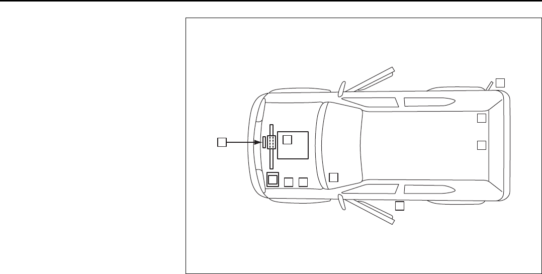
LOCATION OF WARNING
MESSAGES
Read and follow all of the warnings (labels
etc.) on your vehicle. Make sure you
understand all of them. Keep them on the
vehicle. Do not remove the messages for
any reason. If a label comes off or the
messages become difficult to read, have it
corrected by your SUZUKI dealer.
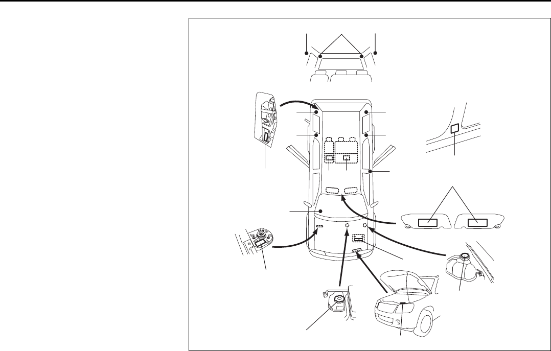
1. Airbag warning labels
(on both sunvisors)
2. Jacking warning label
3. Brake fluid cap message
4. Surge tank cap message
5. Dynamo meter warning label
6. Air conditioner warning label
7. Battery label
8. Air bag warning tag
9. Side air bag warning label
10. Side air bag warning label
(3 seats model only)
11. Pretensioner warning label
12. Second seat folding warning label
910 9
12 12
9
10
9
10
11
11
1
4
6
7
3
5
8
2
Driver Passenger

0-1
78J00-03E
FOREWORD
All information in this manual is based
on the latest product information avail-
able at the time of publication. Due to
improvements or other changes, there
may be discrepancies between informa-
tion in this manual and your vehicle.
SUZUKI MOTOR CORPORATION
reserves the right to make production
changes at any time, without notice and
without incurring any obligation to
make the same or similar changes to
vehicles previously built or sold.
SUZUKI MOTOR CORPORATION
believes in conservation and protection of
Earth’s natural resources.
To that end, we encourage every vehicle
owner to recycle, trade in, or properly dis-
pose of, as appropriate, used motor oil,
coolant, and other fluids, batteries and
tires.
IF YOU HAVE ANY PROBLEMS WITH
YOUR SUZUKI:
Please review the New Vehicle Warranty
Information booklet supplied with your
SUZUKI. Should you have a question or
problem regarding the warranty or service
of your vehicle, please take the following
action:
Consult the Service Manager and the
Owner of the Suzuki Automotive Dealer-
ship. Explain your problem and ask for
their assistance in resolving your problem.
The Owner of the dealership is in the very
best position to assist you as he or she is
vitally concerned with your continued satis-
faction.
If you are still in need of additional informa-
tion, or if you are dissatisfied, request that
your dealer arrange a meeting with your
District Service Manager.
If, after doing so, you still require further
assistance, and you purchased your
SUZUKI in the continental United States,
please contact the American Suzuki Cus-
tomer Relations Department by telephone
at 1-800-934-0934 or in writing at:
American Suzuki Motor Corporation
Automotive Customer Relations
3251 East Imperial Highway
Brea, CA 92821-6795
If you purchased your SUZUKI in Canada
please contact the Suzuki Canada Cus-
tomer Relations Department by telephone
at 1-905-889-2677 extension 2254 or in
writing at:
Suzuki Canada Inc.
Customer Relations
100 East Beaver Creek Road
Richmond Hill, On
L4B 1J6
In the event you require assistance related
to your SUZUKI, while temporarily travel-
ling in either the United States or Canada,
you may wish to contact the Suzuki Cus-
tomer Relations Department directly of the
country in which you are temporarily oper-
ating your vehicle.
Please be certain to provide us with the fol-
lowing information: the model, Vehicle
Identification Number, mileage, accesso-
ries involved, event dates, your concern,
and any other comments which you may
have. When we receive your correspon-
dence, we will be pleased to contact the
Owner of your dealership and assist in
resolving your concern.
For owners outside the continental United
States, please refer to the distributor’s
address listed in your Warranty Information
booklet.
0-2
78J00-03E
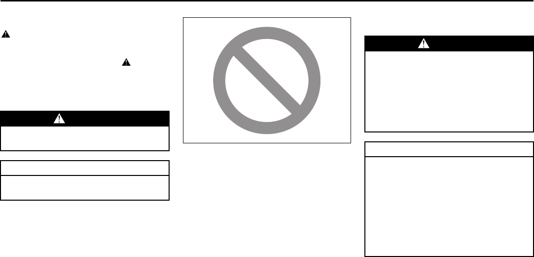
IMPORTANT
WARNING/CAUTION/NOTE
Please read this manual and follow its
instructions carefully. To emphasize spe-
cial information, the symbol and the
words WARNING, CAUTION and NOTE
have special meanings. Pay special atten-
tion to the messages highlighted by these
signal words:
NOTE:
Indicates special information to make
maintenance easier or instructions clearer.
75F135
The circle with a slash in this manual
means “Don’t do this” or “Don’t let this hap-
pen”.
MODIFICATION WARNING
WARNING
Indicates a potential hazard that
could result in death or injury.
CAUTION
Indicates a potential hazard that
could result in vehicle damage.
WARNING
Do not modify this vehicle. Modifica-
tion could adversely affect safety,
handling, performance or durability
and may violate governmental regu-
lations. In addition, damage or perfor-
mance problems resulting from
modification may not be covered
under warranty.
CAUTION
Improper installation of mobile com-
munication equipment such as cellu-
lar telephones or CB (Citizen’s Band)
radios may cause electronic interfer-
ence with your vehicle’s ignition sys-
tem, resulting in vehicle performance
problems. Consult your SUZUKI
dealer or qualified service technician
for advice on installing such mobile
communication equipment.
0-3
78J00-03E
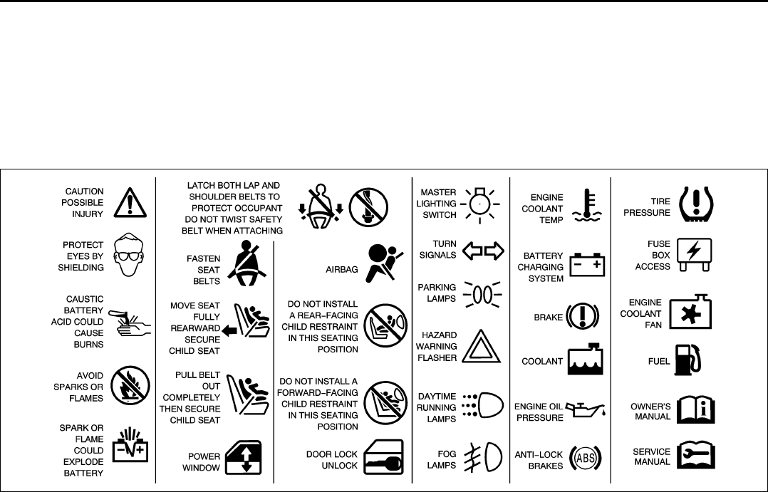
Vehicle Symbols
Your vehicle has components and labels that use symbols instead of text. Symbols, used on your vehicle, are shown along with the text
describing the operation or information relating to a specific component, control, message, gauge or indicator.
If you need help figuring out a specific name of a component, gauge or indicator, reference the following topics:
• Seats and Restraint Systems in Section
1
• Features and Controls in Section 2
• Instrument Panel Overview in Section 3
• Climate Controls in Section 3
• Warning Lights, gauges and Indicators
in Section 3
• Audio System(s) in Section 3
• Engine Compartment Overview in Sec-
tion 5
These are some examples of vehicle symbols you may find on your vehicle:
809119

0-4
78J00-03E

SEATS AND RESTRAINT SYSTEMS
1
78J00-03E
SEATS AND RESTRAINT SYSTEMS
Front Seats .......................................................................... 1-1
Rear Seats ............................................................................ 1-6
Safety Belts .......................................................................... 1-9
Child Restraints ................................................................... 1-18
Airbag System ..................................................................... 1-33
Restraint System Check ..................................................... 1-42
1-1
SEATS AND RESTRAINT SYSTEMS
78J00-03E
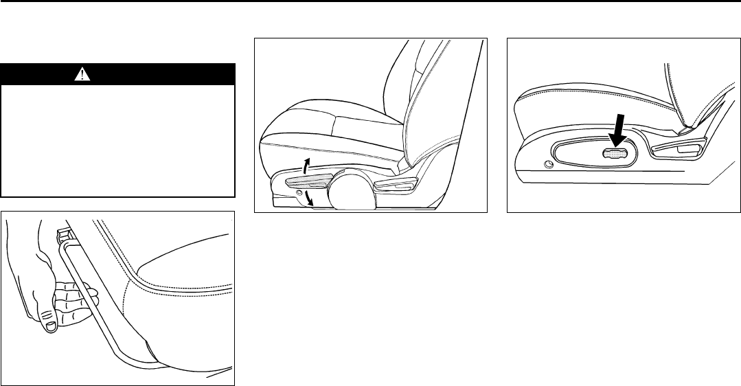
Front Seats
Manual Seats
808318
Lift the bar located under the front of the
seat to unlock it. Slide the seat to where
you want it and release the bar. Try to
move the seat with your body to be sure
the seat is locked in place.
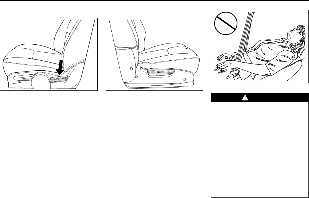
Driver Seat Height Adjuster
1618867
If your vehicle has a manual driver seat
height adjuster, it is located on the out-
board side of the seat near the front of the
seat cushion. To raise the seat, move the
lever upward repeatedly until the seat is at
the desired height. To lower the seat, move
the lever downward repeatedly until the
seat is at the desired height.
Power Seat
1407195
If the vehicle has a power seat, the control
used to operate it is located on the out-
board side of the driver’s seat. To adjust
the seat do any of the following:
• Move the seat forward or rearward by
sliding the control forward or rearward.
• Raise or lower the front part of the seat
cushion by moving the front of the con-
trol up or down.
• Raise or lower the rear part of the seat
cushion by moving the rear of the control
up or down.
WARNING
You can lose control of the vehicle if
you try to adjust a manual driver’s
seat while the vehicle is moving. The
sudden movement could startle and
confuse you, or make you push a
pedal when you do not want to.
Adjust the driver’s seat only when the
vehicle is not moving.
1-2
SEATS AND RESTRAINT SYSTEMS
78J00-03E
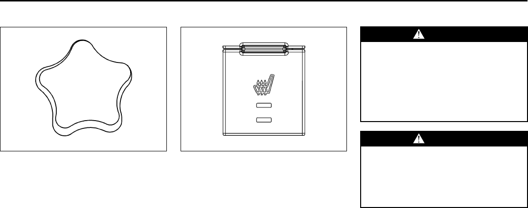
Manual Lumbar
1211985
If your vehicle has this feature, the knob is
located on the front of the driver seat lower
cushion on the inboard side.
Turn the knob clockwise or counterclock-
wise to increase or decrease the lumbar
support.
Heated Seats
1761660
If your vehicle has heated seats, the
switches are located on the instrument
panel near the climate controls.
The ignition must be on for the heated
seats to operate.
Press the switch, nearest to the seat, once
to turn the heated seat on to the high set-
ting. Both indicator lights will be lit. Press
the switch a second time to turn the heated
seat to the low setting. One indicator light
will be lit. Press the switch a third time to
turn the heated seat off.
Manual Reclining Seatbacks
WARNING
You can lose control of the vehicle if
you try to adjust a manual driver’s
seat while the vehicle is moving. The
sudden movement could startle and
confuse you, or make you push a
pedal when you do not want to.
Adjust the driver’s seat only when the
vehicle is not moving.
WARNING
If the seatback is not locked, it could
move forward in a sudden stop or
crash. That could cause injury to the
person sitting there. Always push
and pull on the seatback to be sure it
is locked.
1-3
SEATS AND RESTRAINT SYSTEMS
78J00-03E
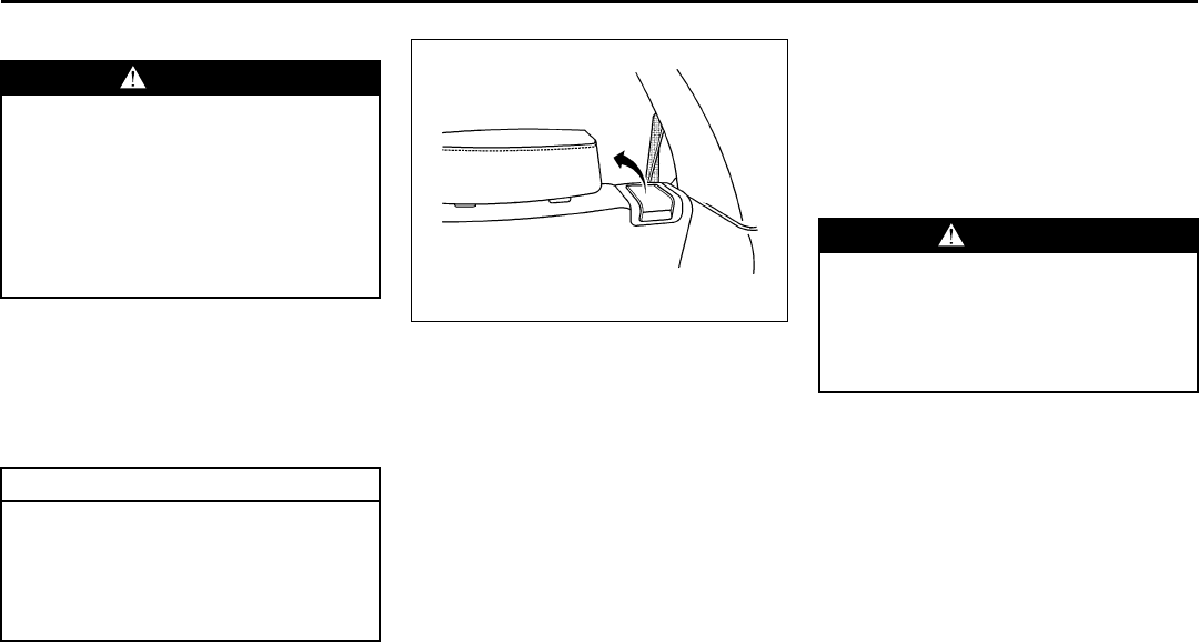
Driver’s seat with manual recline and
manual height adjuster shown
1618868
To adjust the seatback on the driver’s seat,
lift the lever on the rear outboard side of
the seat and move the seatback to the
desired position. Then release the lever to
lock the seatback in place.
Passenger seat with folding seatback
option shown
1618866
To adjust the seatback on the front passen-
ger’s seat, lift the lever on the outboard
side of the seat and move the seatback to
the desired position. Then release the
lever to lock the seatback in place. If your
front passenger’s seat is a flat folding seat,
you must fully raise the lever to disengage
the seatback.
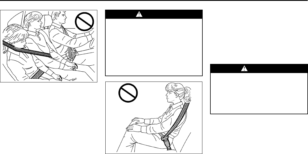
806881
WARNING
Sitting in a reclined position when
your vehicle is in motion can be dan-
gerous. Even if you buckle up, your
safety belts cannot do their job when
you are reclined like this.
The shoulder belt cannot do its job
because it will not be against your
body. Instead, it will be in front of
you. In a crash, you could go into it,
receiving neck or other injuries.
The lap belt cannot do its job either.
In a crash, the belt could go up over
your abdomen. The belt forces would
be there, not at your pelvic bones.
This could cause serious internal
injuries.
(Continued)
1-4
SEATS AND RESTRAINT SYSTEMS
78J00-03E
Do not have a seatback reclined if your
vehicle is moving.
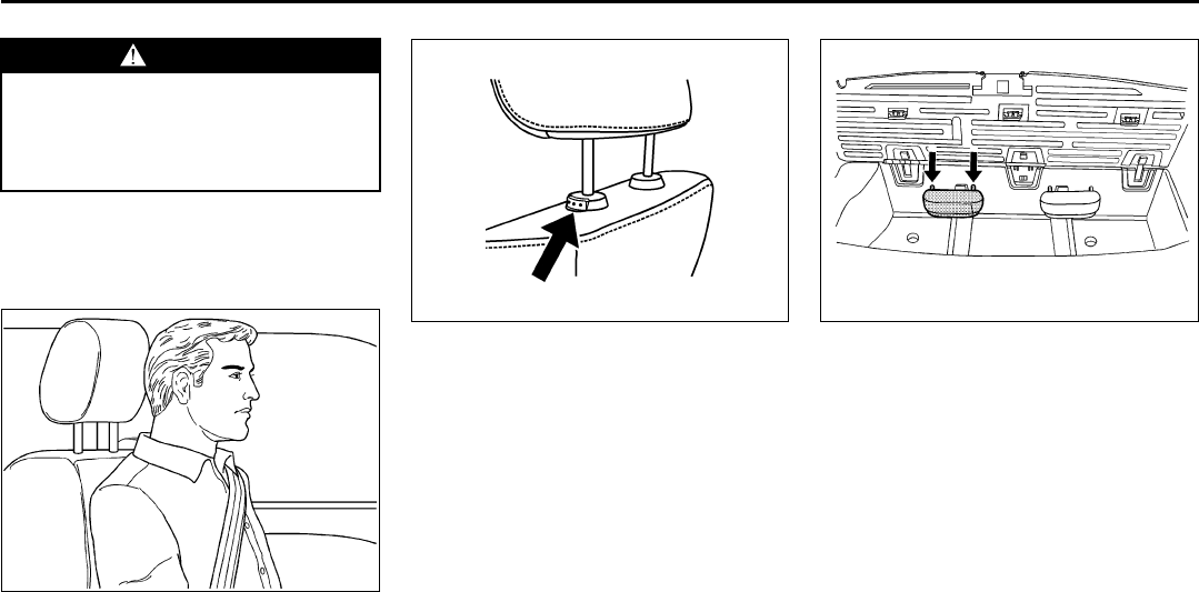
Head Restraints
805677
Adjust the head restraint so that the top of
the restraint is at the same height as the
top of the occupant’s head. This position
reduces the chance of a neck injury in a
crash.
1525254
Pull the head restraint up to raise it. To
lower the head restraint, press the button,
located on the top of the seatback, and
push the restraint down.
The third row head rests adjust like the
front seat head restraints.
1811484
The third row seat head rests can be
removed from the seatback. To do this,
press the button, located on the top of the
seatback, and pull them out from the seat-
back. Store the head rest, front side facing
up, in the compartment behind the third
row, by inserting the head rest posts into
the slots in the storage area.
WARNING
(Continued)
For proper protection when the vehi-
cle is in motion, have the seatback
upright. Then sit well back in the seat
and wear your safety belt properly.
1-5
SEATS AND RESTRAINT SYSTEMS
78J00-03E
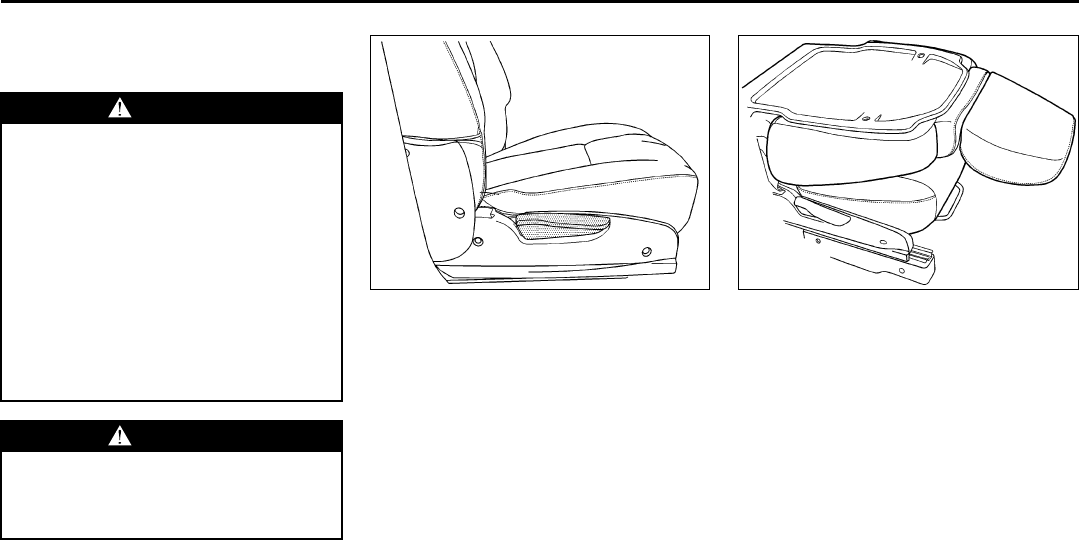
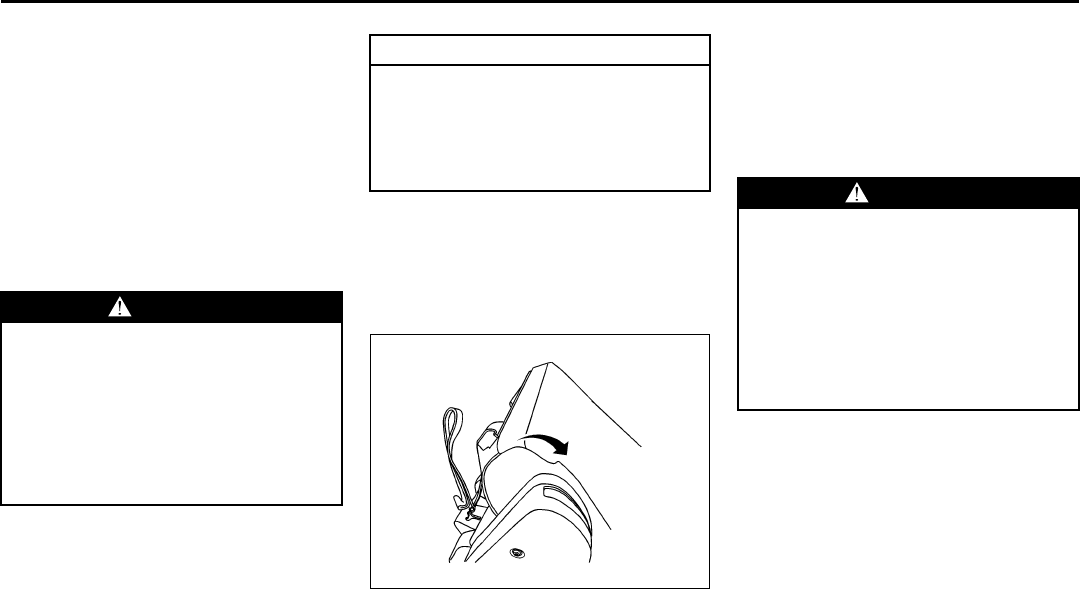
Passenger Folding Seatback
The front passenger’s seatback may fold
flat.
To fold the seatback, do the following:
1) Lower the head restraint all the way.
2) Lift the bar under the front of the seat to
unlock it. Slide the seat as far back as it
will go and release the bar. Try to move
the seat back and forth to make sure it
is locked into place.
1618866
3) Lift the recliner lever, located on the
outboard side of the seat, up fully and
fold the seatback forward until it disen-
gages.
1618864
4) Continue to fold the seat forward until it
locks in the folded position.
5) Pull up on the seatback to be sure it is
locked.
WARNING
If you fold the seatback forward to
carry longer objects, such as skis, be
sure any such cargo is not near an
airbag. In a crash, an inflating airbag
might force that object toward a per-
son. This could cause severe injury
or even death. Secure objects away
from the area in which an airbag
would inflate. For more information,
refer to “Where Are the Airbags?” in
this section and refer to “Loading
Your Vehicle” in “Your Driving, the
Road, and Your Vehicle” in the “Driv-
ing Your Vehicle” section.
WARNING
Things you put on this seatback can
strike and injure people in a sudden
stop or turn, or in a crash. Remove or
secure all items before driving.
1-6
SEATS AND RESTRAINT SYSTEMS
78J00-03E
To raise the seatback, do the following:
1) Lift the recliner lever, located on the
outboard side of the seat, up fully and
push up on the seatback.
2) Continue raising the seatback until the
seatback re-engages.
3) Push and pull on the seatback to make
sure it is locked in place.
The recliner lever is also used to recline
the seatback while a passenger is seated.
Refer to “Manual Reclining Seatbacks” in
this section.
Rear Seats
Split Folding the Second Row Seat
The second row split bench seatbacks
have four available positions – folded for-
ward, upright, partially reclined, or fully
reclined. Both of the seatbacks can be
moved to any of the four positions indepen-
dent of the other seatback position.
To fold the seatback down, do the follow-
ing:
1) Ensure all three of the safety belts are
unbuckled and removed from the child
comfort guide, and the front seatbacks
are not reclined.
2) Lower the headrest.
1406907
3) Lift the lever located on the top of the
seatback to release the seatback.
4) Fold the seatback forward.
WARNING
If the seatback is not locked, it could
move forward in a sudden stop or
crash. That could cause injury to the
person sitting there. Always push
and pull on the seatback to be sure it
is locked.
WARNING
If the seatback is not locked, it could
move forward in a sudden stop or
crash. That could cause injury to the
person sitting there. Always push
and pull on the seatback to be sure it
is locked.
WARNING
A safety belt that is improperly
routed, not properly attached, or
twisted will not provide the protection
needed in a crash. The person wear-
ing the belt could be seriously
injured. After raising the rear seat-
back, always check to be sure that
the safety belts are properly routed
and attached, and are not twisted.
CAUTION
Folding a rear seat with the safety
belts still fastened may cause dam-
age to the seat or the safety belts.
Always unbuckle the safety belts and
return them to their normal stowed
position before folding a rear seat.
1-7
SEATS AND RESTRAINT SYSTEMS
78J00-03E
5) Push and pull on the seatback to make
sure it is locked.
To recline the seatback, do the following:
1) Lift and hold the lever located on top of
the seatback.
2) Tilt the seatback rearward, then release
the lever when the seatback is in the
desired position.
3) Push and pull on the seatback to make
sure it is locked.
Folding and Tumbling the Seat(s)
To fold and tumble the seat, do the follow-
ing:
1) Make sure that there is nothing under,
in front of, or on the seat.
2) Fold the seatback forward.
Leaving the seatback in this position
creates a flat load floor.
If the seatback cannot fold flat, try mov-
ing the front seat forward and/or put the
front seatback in the upright position.
1831564
3) Use the pullstrap to release the rear of
the seat from the floor. As you use the
pullstrap, pull forward on the seat to lift
it into its tumbled position.
Returning the Seat(s) to the Sitting
Position
To return the seat to the sitting position, do
the following:
1) Pull the seat down until it latches to the
floor. Push and pull on the seat cushion
to make sure it is locked.
2) Lift the seatback and push it rearward.
Push and pull on the seatback to make
sure it is locked.
WARNING
Be sure to return the seat to the pas-
senger seating position when fin-
ished. Push and pull on the seat to
make sure it is locked into place.
Never use the third row seating posi-
tion while the second row is folded,
or folded and tumbled. This could
cause injury in a sudden stop or
crash.
CAUTION
Folding a rear seat with the safety
belts still fastened may cause dam-
age to the seat or the safety belts.
Always unbuckle the safety belts and
return them to their normal stowed
position before folding a rear seat.
WARNING
If the seatback is not locked, it could
move forward in a sudden stop or
crash. That could cause injury to the
person sitting there. Always push
and pull on the seatback to be sure it
is locked.
Do not hit or entrap any part of a third
row seat occupant’s body when
returning the folded or tumbled sec-
ond row seat to the floor.
1-8
SEATS AND RESTRAINT SYSTEMS
78J00-03E
Third Row Seat
If the vehicle has a third row seat, the seat-
back(s) can be folded.
Folding the Seatback(s)
To fold the seatback, do the following:
1) Remove all items on the seat cushion.
1811392
2) Lift the lever, located on the top of the
seatback on the outboard side of the
seat and fold the seatback forward.
Unfolding the Seatback(s)
To return the seatback to the upright posi-
tion, do the following:
1) Open the liftgate to access the pullstrap
for the seat.
2) Use the pullstrap on the seatback to
pull the seatback up until it locks into
the upright position.
3) Push and pull on the seatback to make
sure it is locked.
WARNING
Be sure to return the seat to the pas-
senger seating position when fin-
ished. Push and pull on the seat to
make sure it is locked into place.
Never use the third row seating posi-
tion while the second row is folded,
or folded and tumbled. This could
cause injury in a sudden stop or
crash.
CAUTION
Folding a rear seat with the safety
belts still fastened may cause dam-
age to the seat or the safety belts.
Always unbuckle the safety belts and
return them to their normal stowed
position before folding a rear seat.
WARNING
If the seatback is not locked, it could
move forward in a sudden stop or
crash. That could cause injury to the
person sitting there. Always push
and pull on the seatback to be sure it
is locked.
1-9
SEATS AND RESTRAINT SYSTEMS
78J00-03E
Safety Belts
Safety Belts: They Are for Everyone
This part of the manual tells you how to
use safety belts properly. It also tells you
some things you should not do with safety
belts.
Your vehicle has indicators to remind you
and your passengers to buckle your safety
belts. Refer to “Safety Belt Reminder Light”
and “Passenger Safety Belt Reminder
Light” in “Warning Lights, Gages, and Indi-
cators” in the “Instrument Panel” section.
In most states and in all Canadian prov-
inces, the law says to wear safety belts.
Here is why: They work.
You never know if you will be in a crash. If
you do have a crash, you do not know if it
will be a bad one.
A few crashes are mild, and some crashes
can be so serious that even buckled up, a
person would not survive. But most
crashes are in between. In many of them,
people who buckle up can survive and
sometimes walk away. Without belts they
could have been badly hurt or killed.
After more than 40 years of safety belts in
vehicles, the facts are clear. In most
crashes buckling up does matter ... a lot!
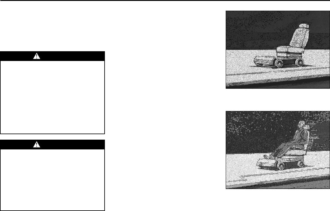
Why Safety Belts Work
When you ride in or on anything, you go as
fast as it goes.
806079
Take the simplest vehicle. Suppose it is
just a seat on wheels.
805926
Put someone on it.
WARNING
Do not let anyone ride where he or
she cannot wear a safety belt prop-
erly. If you are in a crash and you are
not wearing a safety belt, your inju-
ries can be much worse. You can hit
things inside the vehicle or be
ejected from it. You can be seriously
injured or killed. In the same crash,
you might not be, if you are buckled
up. Always fasten your safety belt,
and check that your passengers’
belts are fastened properly too.
WARNING
It is extremely dangerous to ride in a
cargo area, inside or outside of a
vehicle. In a collision, people riding
in these areas are more likely to be
seriously injured or killed. Do not
allow people to ride in any area of
your vehicle that is not equipped with
seats and safety belts. Be sure every-
one in your vehicle is in a seat and
using a safety belt properly.
1-10
SEATS AND RESTRAINT SYSTEMS
78J00-03E
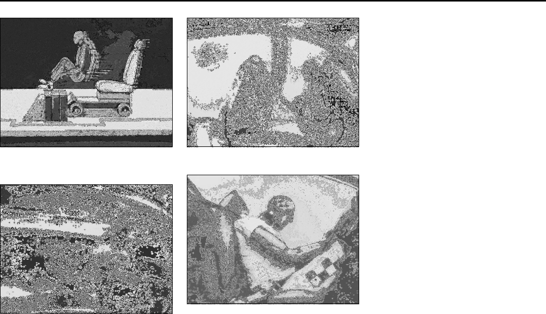
805928
Get it up to speed. Then stop the vehicle.
The rider does not stop.
805931
The person keeps going until stopped by
something. In a real vehicle, it could be the
windshield...
809245
or the instrument panel...
805935
or the safety belts!
With safety belts, you slow down as the
vehicle does. You get more time to stop.
You stop over more distance, and your
strongest bones take the forces. That is
why safety belts make such good sense.
Questions and Answers About
Safety Belts
Question:
Will I be trapped in the vehicle after an
accident if I am wearing a safety belt?
Answer:
You could be – whether you are wearing a
safety belt or not. But you can unbuckle a
safety belt, even if you are upside down.
And your chance of being conscious dur-
ing and after an accident, so you can
unbuckle and get out, is much greater if
you are belted.
Question:
If my vehicle has airbags, why should I
have to wear safety belts?
Answer:
Airbags are supplemental systems only; so
they work with safety belts – not instead of
them. Every airbag system ever offered for
sale has required the use of safety belts.
Even if you are in a vehicle that has air-
bags, you still have to buckle up to get the
most protection. That is true not only in
frontal collisions, but especially in side and
other collisions.
1-11
SEATS AND RESTRAINT SYSTEMS
78J00-03E
Question:
If I am a good driver, and I never drive
far from home, why should I wear safety
belts?
Answer:
You may be an excellent driver, but if you
are in an accident – even one that is not
your fault – you and your passengers can
be hurt. Being a good driver does not pro-
tect you from things beyond your control,
such as bad drivers.
Most accidents occur within 25 miles (40
km) of home. And the greatest number of
serious injuries and deaths occur at
speeds of less than 40 mph (65 km/h).
Safety belts are for everyone.
How to Wear Safety Belts Properly
This part is only for people of adult size.
Be aware that there are special things to
know about safety belts and children. And
there are different rules for smaller children
and babies. If a child will be riding in your
vehicle, refer to “Older Children” or “Infants
and Young Children” in this section. Follow
those rules for everyone’s protection.
First, you will want to know which restraint
systems your vehicle has.
We will start with the driver position.
Driver Position
Lap-Shoulder Belt
The driver has a lap-shoulder belt. Here is
how to wear it properly.
1) Close and lock the door.
2) Adjust the seat so you can sit up
straight. To see how, see “Seats” in the
Index.
1378723
3) Pick up the latch plate and pull the belt
across you. Do not let it get twisted.
The lap-shoulder belt may lock if you
pull the belt across you very quickly. If
this happens, let the belt go back
slightly to unlock it. Then pull the belt
across you more slowly.
4) Push the latch plate into the buckle until
it clicks.
Pull up on the latch plate to make sure
it is secure. If the belt is not long
enough, refer to “Safety Belt Extender”
in this section.
Make sure the release button on the
buckle is positioned so you would be
able to unbuckle the safety belt quickly
if you ever had to.
5) Move the shoulder belt height adjuster
to the height that is right for you.
Improper shoulder belt height adjust-
ment could reduce the effectiveness of
the safety belt in a crash. Refer to
“Shoulder Belt Height Adjustment” in
this section.
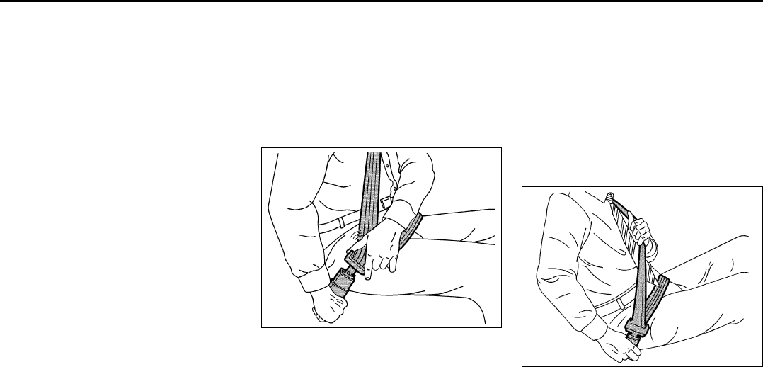
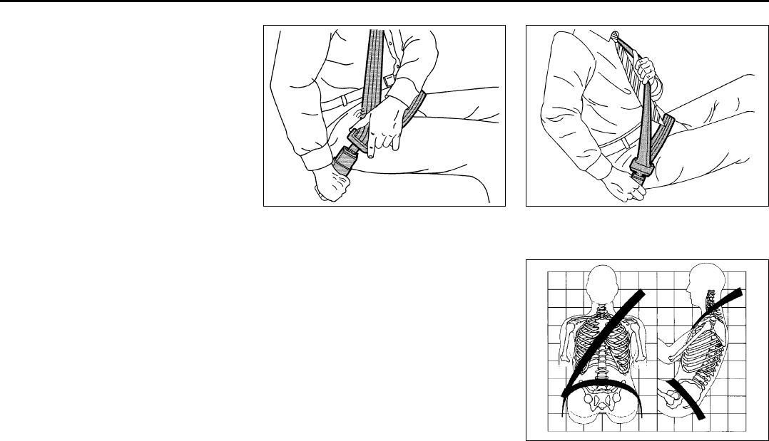
1378907
6) To make the lap part tight, pull up on
the shoulder belt.
1-12
SEATS AND RESTRAINT SYSTEMS
78J00-03E
It may be necessary to pull stitching on the
safety belt through the latch plate to fully
tighten the lap belt on smaller occupants.
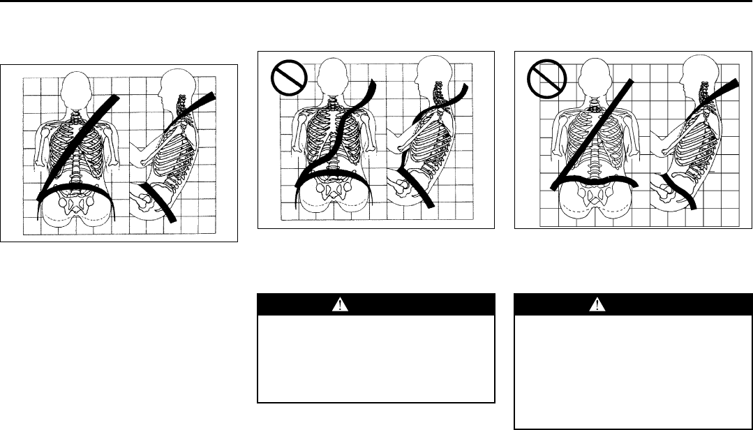
809246
The lap part of the belt should be worn low
and snug on the hips, just touching the
thighs. In a crash, this applies force to the
strong pelvic bones. And you would be
less likely to slide under the lap belt. If you
slid under it, the belt would apply force at
your abdomen. This could cause serious
or even fatal injuries. The shoulder belt
should go over the shoulder and across
the chest. These parts of the body are best
able to take belt restraining forces.
The safety belt locks if there is a sudden
stop or crash.
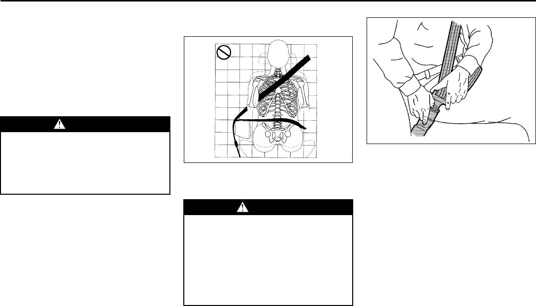
Question:
What is wrong with this?
810723
Answer:
The shoulder belt is too loose. It will not
give nearly as much protection this way.
Question:
What is wrong with this?
1697414
Answer:
The lap belt is too loose. It will not give
nearly as much protection this way.
WARNING
You can be seriously hurt if your
shoulder belt is too loose. In a crash,
you would move forward too much,
which could increase injury. The
shoulder belt should fit against your
body.
WARNING
You can be seriously hurt if your lap
belt is too loose. In a crash, you
could slide under the lap belt and
apply force at your abdomen. This
could cause serious or even fatal
injuries. The lap belt should be worn
low and snug on the hips, just touch-
ing the thighs.
1-13
SEATS AND RESTRAINT SYSTEMS
78J00-03E
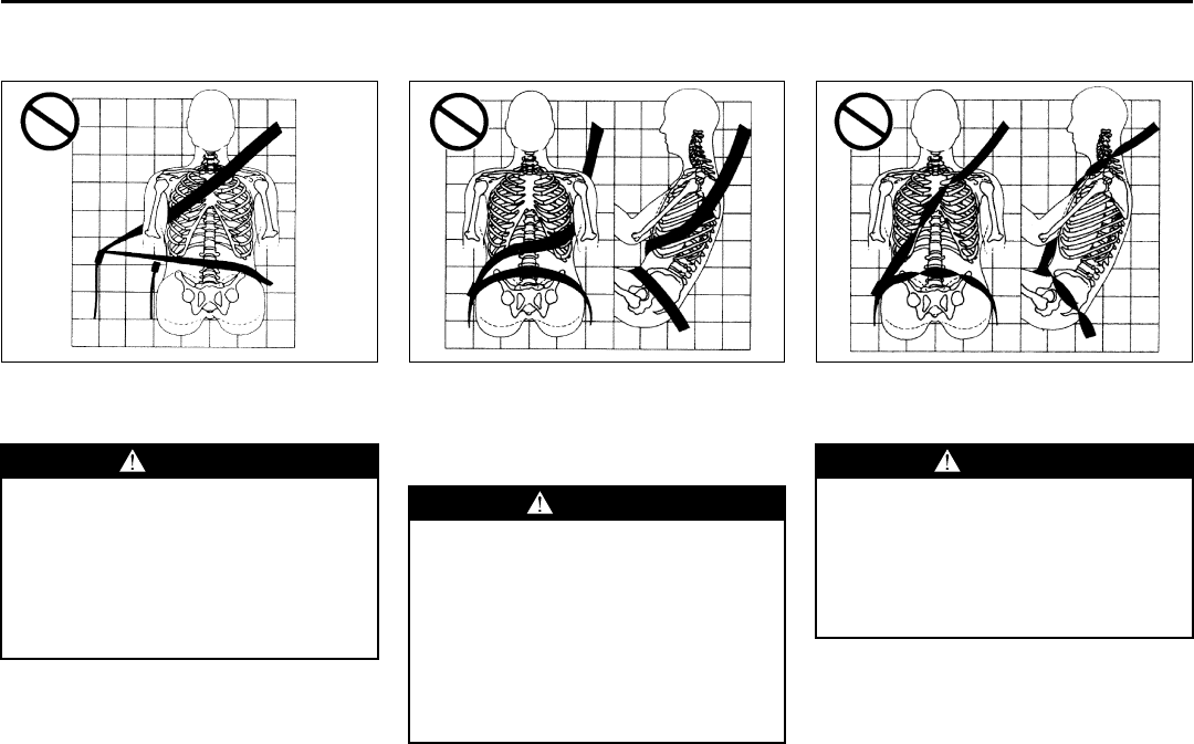
Question:
What is wrong with this?
805942
Answer:
The belt is buckled in the wrong place.
Question:
What is wrong with this?
805947
Answer:
The shoulder belt is worn under the arm. It
should be worn over the shoulder at all
times.
Question:
What is wrong with this?
805951
Answer:
The belt is twisted across the body.
WARNING
You can be seriously injured if your
belt is buckled in the wrong place like
this. In a crash, the belt would go up
over your abdomen. The belt forces
would be there, not at the pelvic
bones. This could cause serious
internal injuries. Always buckle your
belt into the buckle nearest you.
WARNING
You can be seriously injured if you
wear the shoulder belt under your
arm. In a crash, your body would
move too far forward, which would
increase the chance of head and neck
injury. Also, the belt would apply too
much force to the ribs, which are not
as strong as shoulder bones. You
could also severely injure internal
organs like your liver or spleen.
WARNING
You can be seriously injured by a
twisted belt. In a crash, you would
not have the full width of the belt to
spread impact forces. If a belt is
twisted, make it straight so it can
work properly, or ask your dealer to
fix it.
1-14
SEATS AND RESTRAINT SYSTEMS
78J00-03E
1378915
To unlatch the belt, push the button on the
buckle. The belt should go back out of the
way.
Before you close the door, be sure the belt
is out of the way. If you slam the door on it,
you can damage both the belt and your
vehicle.
Shoulder Belt Height Adjustment
Before you begin to drive, move the shoul-
der belt height adjuster to the height that is
right for you.
Adjust the height so that the shoulder por-
tion of the belt is centered on your shoul-
der. The belt should be away from your
face and neck, but not falling off your
shoulder. Improper shoulder belt height
adjustment could reduce the effectiveness
of the safety belt in a crash.
1507374
To move it up or down, squeeze the
release buttons (A) together and move the
height adjuster to the desired position.
After you move the height adjuster to
where you want it, try to move it up or
down without squeezing the release but-
tons to make sure it has locked into posi-
tion.
Safety Belt Use During Pregnancy
Safety belts work for everyone, including
pregnant women. Like all occupants, they
are more likely to be seriously injured if
they do not wear safety belts.
1379057
A pregnant woman should wear a lap-
shoulder belt, and the lap portion should
be worn as low as possible, below the
rounding, throughout the pregnancy.
The best way to protect the fetus is to pro-
tect the mother. When a safety belt is worn
properly, it is more likely that the fetus will
not be hurt in a crash. For pregnant
women, as for anyone, the key to making
safety belts effective is wearing them prop-
erly.
1-15
SEATS AND RESTRAINT SYSTEMS
78J00-03E
Right Front Passenger Position
To learn how to wear the right front pas-
senger’s safety belt properly, refer to
“Driver Position” in this section.
The right front passenger’s safety belt
works the same way as the driver’s safety
belt – except for the following.
If you ever pull the shoulder portion of the
belt out all the way, you will engage the
child restraint locking feature. If this hap-
pens, just let the belt go back all the way
and start again.
When the safety belt is not in use, slide the
latch plate up the safety belt webbing. The
latch plate should rest on the stitching on
the safety belt, near the guide loop.
Rear Seat Passengers
It is very important for rear seat passen-
gers to buckle up! Accident statistics show
that unbelted people in the rear seat are
hurt more often in crashes than those who
are wearing safety belts.
Rear passengers who are not safety belted
can be thrown out of the vehicle in a crash.
And they can strike others in the vehicle
who are wearing safety belts.
Lap-Shoulder Belt
All rear seat positions have lap-shoulder
belts. Here is how to wear one properly.
1378723
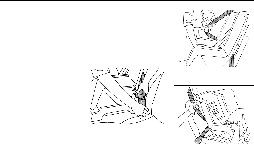
1) Pick up the latch plate and pull the belt
across you. Do not let it get twisted.
The shoulder belt may lock if you pull
the belt across you very quickly. If this
happens, let the belt go back slightly to
unlock it. Then pull the belt across you
more slowly.
2) Push the latch plate into the buckle until
it clicks.
Pull up on the latch plate to make sure
it is secure.
When the shoulder belt is pulled out all
the way, it will lock. If it does, let it go
back all the way and start again.
If the belt is not long enough, refer to
“Safety Belt Extender” in this section.
Make sure the release button on the
buckle is positioned so you would be
able to unbuckle the safety belt quickly
if you ever had to.
1378907
3) To make the lap part tight, pull up on
the shoulder part.
805902
The lap part of the belt should be worn low
and snug on the hips, just touching the
thighs. In a crash, this applies force to the
1-16
SEATS AND RESTRAINT SYSTEMS
78J00-03E
strong pelvic bones. And you would be
less likely to slide under the lap belt. If you
slid under it, the belt would apply force at
your abdomen. This could cause serious
or even fatal injuries. The shoulder belt
should go over the shoulder and across
the chest. These parts of the body are best
able to take belt restraining forces.
The safety belt locks if there is a sudden
stop or a crash.
Question:
What is wrong with this?
811744
Answer:
The belt is over an armrest.
1378915
To unlatch the belt, push the button on the
buckle.
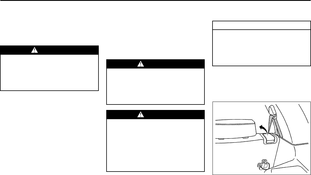
Rear Safety Belt Comfort Guides
Rear shoulder belt comfort guides may
provide added safety belt comfort for older
children who have outgrown booster seats
and for some adults. When installed on a
shoulder belt, the comfort guide positions
the belt away from the neck and head.
There is one guide available for each out-
board passenger position in the rear seat.
Here is how to install a comfort guide to
the safety belt:
1) Remove the guide from its storage clip
on the back of the seatback.
WARNING
You can be seriously hurt if your
shoulder belt is too loose. In a crash,
you would move forward too much,
which could increase injury. The
shoulder belt should fit against your
body.
WARNING
You can be seriously injured if your
belt goes over an armrest like this.
The belt would be much too high. In a
crash, you can slide under the belt.
The belt force would then be applied
at the abdomen, not at the pelvic
bones, and that could cause serious
or fatal injuries. Be sure the belt goes
under the armrests.
1-17
SEATS AND RESTRAINT SYSTEMS
78J00-03E
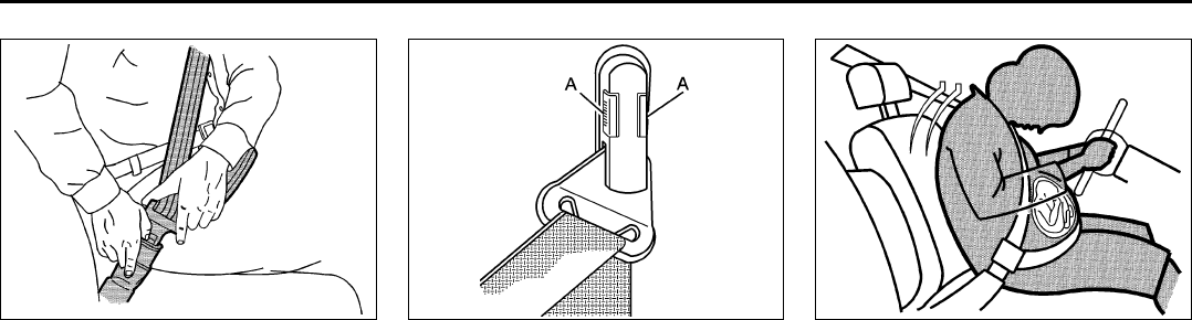
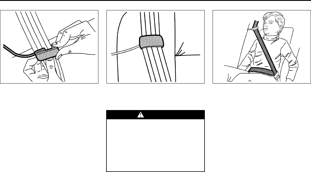
1379299
2) Slide the guide under and past the belt.
The elastic cord must be under the belt.
Then, place the guide over the belt, and
insert the two edges of the belt into the
slots of the guide.
1397291
3) Be sure that the belt is not twisted and it
lies flat. The elastic cord must be under
the belt and the guide on top.
1400065
4) Buckle, position, and release the safety
belt as described in “Rear Seat Passen-
gers” in this section. Make sure that the
shoulder belt crosses the shoulder.
To remove and store the comfort guide,
squeeze the belt edges together so that
you can take them out of the guide. Slide
the guide back onto its storage clip located
on the seatback.
WARNING
A safety belt that is not properly worn
may not provide the protection
needed in a crash. The person wear-
ing the belt could be seriously
injured. The shoulder belt should go
over the shoulder and across the
chest. These parts of the body are
best able to take belt restraining
forces.
1-18
SEATS AND RESTRAINT SYSTEMS
78J00-03E
Safety Belt Pretensioners
Your vehicle has safety belt pretensioners
for the driver and right front passenger.
Although you cannot see them, they are
part of the safety belt assembly. They help
tighten the safety belts during the early
stages of a moderate to severe frontal,
near frontal, rear or side crash, or a roll-
over if the threshold conditions for preten-
sioner activation are met.
Pretensioners work only once. If they acti-
vate in a crash, you will need to get new
ones, and probably other new parts for
your safety belt system. Refer to “Replac-
ing Restraint System Parts After a Crash”
in this section.
Safety Belt Extender
If the vehicle’s safety belt will fasten around
you, you should use it.
But if a safety belt is not long enough, your
dealer will order you an extender. When
you go in to order it, take the heaviest coat
you will wear, so the extender will be long
enough for you. To help avoid personal
injury, do not let someone else use it, and
use it only for the seat it is made to fit. The
extender has been designed for adults.
Never use it for securing child seats. To
wear it, just attach it to the regular safety
belt. For more information see the instruc-
tion sheet that comes with the extender.
Child Restraints
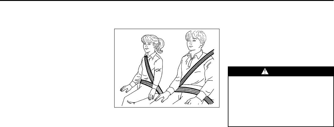
Older Children
1379300
Older children who have outgrown booster
seats should wear the vehicle’s safety
belts.
Question:
What is the proper way to wear safety
belts?
Answer:
An older child should wear a lap-shoulder
belt and get the additional restraint a
shoulder belt can provide. The shoulder
belt should not cross the face or neck. The
lap belt should fit snugly below the hips,
just touching the top of the thighs. It should
never be worn over the abdomen, which
could cause severe or even fatal internal
injuries in a crash.
According to accident statistics, children
are safer when properly restrained in the
rear seating positions than in the front
seating positions.
In a crash, children who are not buckled up
can strike other people who are buckled
up, or can be thrown out of the vehicle.
Older children need to use safety belts
properly.
WARNING
Never do this.
Here two children are wearing the
same belt. The belt cannot properly
spread the impact forces. In a crash,
the two children can be crushed
together and seriously injured. A belt
must be used by only one person at a
time.
1-19
SEATS AND RESTRAINT SYSTEMS
78J00-03E
1379302
Question:
What if a child is wearing a lap-shoulder
belt, but the child is so small that the
shoulder belt is very close to the child’s
face or neck?
Answer:
If the child is sitting in a seat next to a win-
dow, move the child toward the center of
the vehicle. Also refer to “Rear Safety Belt
Comfort Guides” in this section. If the child
is sitting in the center rear seat passenger
position, move the child toward the safety
belt buckle. In either case, be sure that the
shoulder belt still is on the child’s shoulder,
so that in a crash the child’s upper body
would have the restraint that belts provide.
1379303
Wherever the child sits, the lap portion of
the belt should be worn low and snug on
the hips, just touching the child’s thighs.
This applies belt force to the child’s pelvic
bones in a crash.
Infants and Young Children
Everyone in a vehicle needs protection!
This includes infants and all other children.
Neither the distance traveled nor the age
and size of the traveler changes the need,
for everyone, to use safety restraints. In
fact, the law in every state in the United
States and in every Canadian province
says children up to some age must be
restrained while in a vehicle.
Every time infants and young children ride
in vehicles, they should have the protection
provided by appropriate restraints. Young
children should not use the vehicle’s adult
safety belts alone, unless there is no other
choice. Instead, they need to use a child
restraint.
WARNING
Never do this.
Here a child is sitting in a seat that
has a lap-shoulder belt, but the
shoulder part is behind the child. If
the child wears the belt in this way, in
a crash the child might slide under
the belt. The belt’s force would then
be applied right on the child’s abdo-
men. That could cause serious or
fatal injuries. WARNING
Children can be seriously injured or
strangled if a shoulder belt is
wrapped around their neck and the
safety belt continues to tighten.
Never leave children unattended in a
vehicle and never allow children to
play with the safety belts.
1-20
SEATS AND RESTRAINT SYSTEMS
78J00-03E
1379304 1379315
Question:
What are the different types of add-on
child restraints?
Answer:
Add-on child restraints, which are pur-
chased by the vehicle’s owner, are avail-
able in four basic types. Selection of a
particular restraint should take into consid-
eration not only the child’s weight, height,
and age but also whether or not the
restraint will be compatible with the motor
vehicle in which it will be used.
For most basic types of child restraints,
there are many different models available.
When purchasing a child restraint, be sure
it is designed to be used in a motor vehicle.
If it is, the restraint will have a label saying
that it meets federal motor vehicle safety
standards.
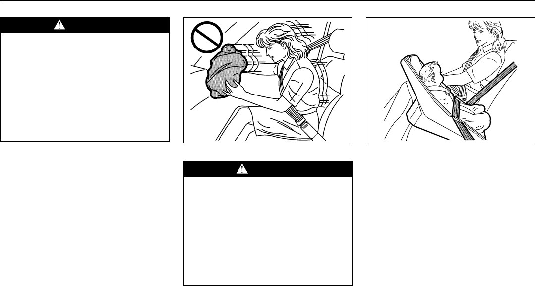
WARNING
People should never hold a baby in
their arms while riding in a vehicle. A
baby does not weigh much – until a
crash. During a crash a baby will
become so heavy it is not possible to
hold it. For example, in a crash at
only 25 mph (40 km/h), a 12 lb (5.5 kg)
baby will suddenly become a 240 lb
(110 kg) force on a person’s arms. A
baby should be secured in an appro-
priate restraint.
WARNING
Children who are up against, or very
close to, any airbag when it inflates
can be seriously injured or killed. Air-
bags plus lap-shoulder belts offer
protection for adults and older chil-
dren, but not for young children and
infants. Neither the vehicle’s safety
belt system nor its airbag system is
designed for them. Young children
and infants need the protection that a
child restraint system can provide.
1-21
SEATS AND RESTRAINT SYSTEMS
78J00-03E
The restraint manufacturer’s instructions
that come with the restraint state the
weight and height limitations for a particu-
lar child restraint. In addition, there are
many kinds of restraints available for chil-
dren with special needs.
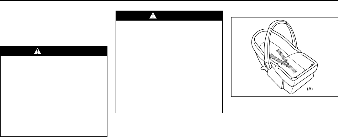
Child Restraint Systems
1379317
An infant car bed (A), a special bed made
for use in a motor vehicle, is an infant
restraint system designed to restrain or
position a child on a continuous flat sur-
face. Make sure that the infant’s head rests
toward the center of the vehicle.
WARNING
Newborn infants need complete sup-
port, including support for the head
and neck. This is necessary because
a newborn infant’s neck is weak and
its head weighs so much compared
with the rest of its body. In a crash,
an infant in a rear-facing seat settles
into the restraint, so the crash forces
can be distributed across the stron-
gest part of an infant’s body, the back
and shoulders. Infants always should
be secured in appropriate infant
restraints.
WARNING
The body structure of a young child
is quite unlike that of an adult or
older child, for whom the safety belts
are designed. A young child’s hip
bones are still so small that the vehi-
cle’s regular safety belt may not
remain low on the hip bones, as it
should. Instead, it may settle up
around the child’s abdomen. In a
crash, the belt would apply force on a
body area that is unprotected by any
bony structure. This alone could
cause serious or fatal injuries. Young
children always should be secured in
appropriate child restraints.
1-22
SEATS AND RESTRAINT SYSTEMS
78J00-03E
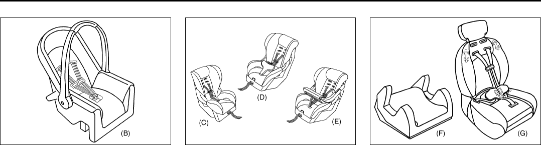
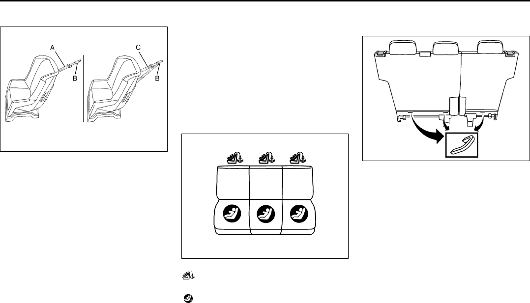
1383218
A rear-facing infant seat (B) provides
restraint with the seating surface against
the back of the infant. The harness system
holds the infant in place and, in a crash,
acts to keep the infant positioned in the
restraint.
1395252
A forward-facing child seat (C–E) provides
restraint for the child’s body with the har-
ness and also sometimes with surfaces
such as T-shaped or shelf-like shields.
1395258
A booster seat (F–G) is a child restraint
designed to improve the fit of the vehicle’s
safety belt system. Some booster seats
have a shoulder belt positioner, and some
high-back booster seats have a five-point
harness. A booster seat can also help a
child to see out the window.
1-23
SEATS AND RESTRAINT SYSTEMS
78J00-03E
Question:
How Should I Use a Child Restraint?
Answer:
A child restraint system is any device
designed for use in a motor vehicle to
restrain, seat, or position children. A built-
in child restraint system is a permanent
part of the motor vehicle. An add-on child
restraint system is a portable one, which is
purchased by the vehicle’s owner. To help
reduce injuries, an add-on child restraint
must be secured in the vehicle. With built-
in or add-on child restraints, the child has
to be secured within the child restraint.
When choosing an add-on child restraint,
be sure the child restraint is designed to be
used in a vehicle. If it is, it will have a label
saying that it meets federal motor vehicle
safety standards. Then follow the instruc-
tions for the restraint. You may find these
instructions on the restraint itself or in a
booklet, or both.
Securing an Add-on Child Restraint
in the Vehicle
To help reduce the chance of injury, the
child restraint must be secured in the vehi-
cle. Child restraint systems must be
secured in vehicle seats by lap belts or the
lap belt portion of a lap-shoulder belt, or by
the LATCH system. Refer to “Lower
Anchors and Tethers for Children
(LATCH)” in this section for more informa-
tion. A child can be endangered in a crash
if the child restraint is not properly secured
in the vehicle.
When securing an add-on child restraint,
refer to the instructions that come with the
restraint which may be on the restraint
itself or in a booklet, or both, and to this
manual. The child restraint instructions are
important, so if they are not available,
obtain a replacement copy from the manu-
facturer.
Keep in mind that an unsecured child
restraint can move around in a collision or
sudden stop and injure people in the vehi-
cle. Be sure to properly secure any child
restraint in your vehicle – even when no
child is in it.
Securing the Child Within the Child
Restraint
There are several systems for securing the
child within the child restraint. One system,
the three-point harness, has straps that
come down over each of the infant’s shoul-
ders and buckle together at the crotch. The
five-point harness system has two shoul-
der straps, two hip straps, and a crotch
strap. A shield may take the place of hip
straps. A T-shaped shield has shoulder
straps that are attached to a flat pad which
rests low against the child’s body. A shelf-
or armrest-type shield has straps that are
attached to a wide, shelf-like shield that
swings up or to the side.
Because there are different systems, it is
important to refer to the instructions that
come with the restraint. A child can be
WARNING
A child can be seriously injured or
killed in a crash if the child restraint
is not properly secured in the vehicle.
Make sure the child restraint is prop-
erly installed in the vehicle using the
vehicle’s safety belt or LATCH sys-
tem, following the instructions that
came with that restraint, and also the
instructions in this manual.
WARNING
A child can be seriously injured or
killed in a crash if the child is not
properly secured in the child
restraint. Make sure the child is prop-
erly secured, following the instruc-
tions that came with that restraint.
1-24
SEATS AND RESTRAINT SYSTEMS
78J00-03E
endangered in a crash if the child is not
properly secured in the child restraint.
Where to Put the Restraint
Accident statistics show that children are
safer if they are restrained in the rear
rather than the front seat. We recommend
that child restraints be secured in a rear
seat, including an infant riding in a rear-
facing infant seat, a child riding in a for-
ward-facing child seat and an older child
riding in a booster seat. Never put a rear-
facing child restraint in the front passenger
seat. Here is why:
There is limited space in the third row rear
seating area. If you want to secure a child
restraint in a rear seating position in the
third row, be sure to study the instructions
that came with your child restraint to see if
there is enough room to secure your seat
properly. If the length of the seat cushion is
too short for your child restraint and you
cannot install it in accordance with the
child restraint manufacturers instructions,
secure it in the second row.
If you need to secure more than one child
restraint in the rear seat, review the follow-
ing illustrations.
NOTE:
Depending on where you place the child
restraint or the size of the child restraint,
you may not be able to access certain
safety belt assemblies for additional pas-
sengers or LATCH anchors for child
restraints. For more information about
where to place the child restraint, refer to
“Lower Anchor and Top Tether Anchor
Locations” in this section.
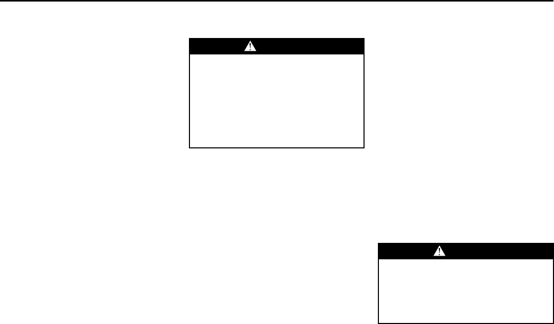
Configurations for Use of Two
Child Restraints
1507695
A. Child restraint using LATCH
B. Occupant prohibited
WARNING
A child in a rear-facing child restraint
can be seriously injured or killed if
the right front passenger's airbag
inflates. This is because the back of
the rear-facing child restraint would
be very close to the inflating airbag.
Even though the passenger sensing
system is designed to turn off the
right front passenger's frontal airbag
if the system detects a rear-facing
child restraint, no system is fail-safe,
and no one can guarantee that an air-
bag will not deploy under some
unusual circumstance, even though
it is turned off. We recommend that
rear-facing child restraints be
secured in the rear seat, even if the
airbag is off.
(Continued)
WARNING
(Continued)
If you need to secure a forward-fac-
ing child restraint in the right front
seat, always move the front passen-
ger seat as far back as it will go. It is
better to secure the child restraint in
a rear seat.
1-25
SEATS AND RESTRAINT SYSTEMS
78J00-03E
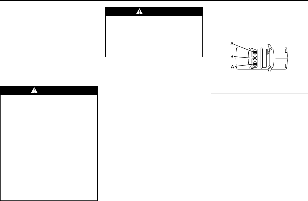
1507697
A. Occupant prohibited
B. Child restraint using LATCH
1507698
A. Child restraint using LATCH
B. No occupant recommended
C. Child restraint or occupant using safety
belt
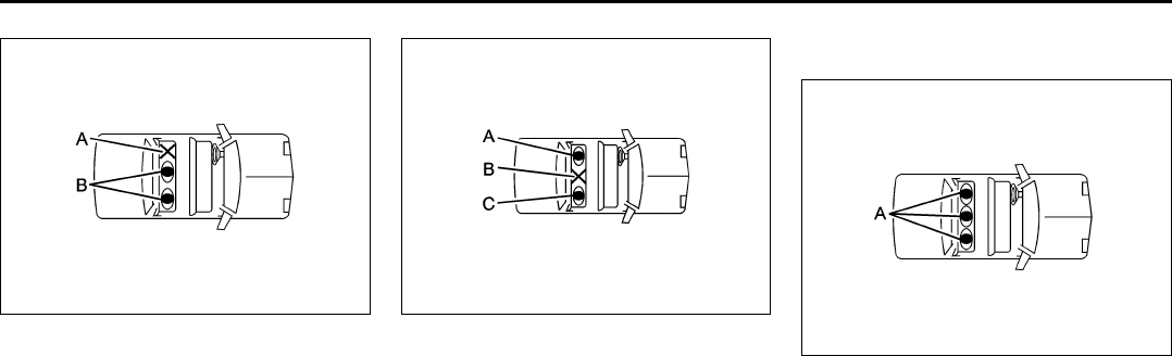
Configurations for Use of Three
Child Restraints
1507710
A. Child restraint or occupant using safety
belt
1-26
SEATS AND RESTRAINT SYSTEMS
78J00-03E
1507704
A. Child restraint or occupant using safety
belt
B. Child restraint using LATCH
Wherever you install a child restraint, be
sure to secure the child restraint properly.
Keep in mind that an unsecured child
restraint can move around in a collision or
sudden stop and injure people in the vehi-
cle. Be sure to properly secure any child
restraint in your vehicle – even when no
child is in it.
Lower Anchors and Tethers for
Children (LATCH)
The LATCH system holds a child restraint
during driving or in a crash. This system is
designed to make installation of a child
restraint easier. The LATCH system uses
anchors in the vehicle and attachments on
the child restraint that are made for use
with the LATCH system.
Make sure that a LATCH-compatible child
restraint is properly installed using the
anchors, or use the vehicle’s safety belts to
secure the restraint, following the instruc-
tions that came with that restraint, and also
the instructions in this manual. When
installing a child restraint with a top tether,
you must also use either the lower anchors
or the safety belts to properly secure the
child restraint. A child restraint must never
be installed using only the top tether and
anchor.
In order to use the LATCH system in your
vehicle, you need a child restraint that has
LATCH attachments. The child restraint
manufacturer will provide you with instruc-
tions on how to use the child restraint and
its attachments. The following explains
how to attach a child restraint with these
attachments in your vehicle.
Not all vehicle seating positions or child
restraints have lower anchors and attach-
ments or top tether anchors and attach-
ments.
Lower Anchors
1550469
Lower anchors (A) are metal bars built into
the vehicle. There are two lower anchors
for each LATCH seating position that will
accommodate a child restraint with lower
attachments (B).
1-27
SEATS AND RESTRAINT SYSTEMS
78J00-03E
Top Tether Anchor
1550581
A top tether (A, C) anchors the top of the
child restraint to the vehicle. A top tether
anchor is built into the vehicle. The top
tether attachment (B) on the child restraint
connects to the top tether anchor in the
vehicle in order to reduce the forward
movement and rotation of the child
restraint during driving or in a crash.
Your child restraint may have a single
tether (A) or a dual tether (C). Either will
have a single attachment (B) to secure the
top tether to the anchor.
Some child restraints that have a top tether
are designed for use with or without the top
tether being attached. Others require the
top tether always to be attached. In Can-
ada, the law requires that forward-facing
child restraints have a top tether, and that
the tether be attached. In the United
States, some child restraints also have a
top tether. Be sure to read and follow the
instructions for your child restraint.
If the child restraint does not have a top
tether, one can be obtained, in kit form, for
many child restraints. Ask the child
restraint manufacturer whether or not a kit
is available.
Lower Anchor and -Top Tether Anchor
Locations
Second Row Seat
1552146
(Top Tether Anchor):
Seating positions with top tether anchors.
(Lower Anchor):
Seating positions with two lower anchors.
Each second row seating position has
exposed metal anchors located in the
crease between the seatback and the seat
cushion.
1708261
The top tether anchors for each second
row seating position are located on the
base of the seatback. Be sure to use an
anchor located on the same side of the
vehicle as the seating position where the
child restraint will be placed.
Do not secure a child restraint in the right
front passenger’s position or the third row,
if a national or local law requires that the
top tether be attached, or if the instructions
that come with the child restraint say that
the top tether must be attached. There is
no place to attach the top tether in this
position.
Accident statistics show that children are
safer if they are restrained in the rear
rather than the front seat. Refer to “Where
1-28
SEATS AND RESTRAINT SYSTEMS
78J00-03E
to Put the Restraint” in this section for
additional information.
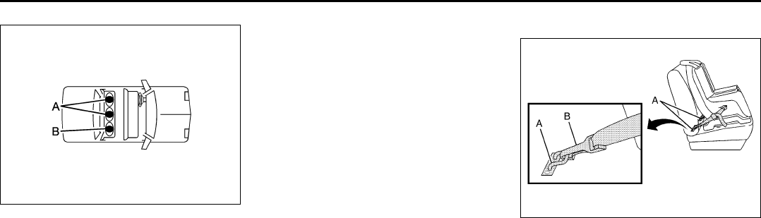
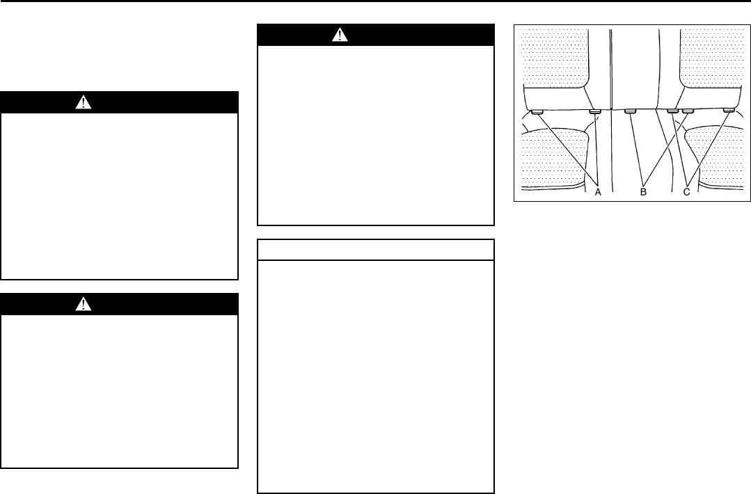
Securing a Child Restraint
Designed for the LATCH System
1252139
A. Passenger’s side rear seat lower
anchors
B. Center rear seat lower anchors
C. Driver’s side rear seat lower anchors
Make sure to attach the child restraint at
the proper anchor location.
This system is designed to make installa-
tion of child restraints easier. When using
lower anchors, do not use the vehicle’s
safety belts. Instead use the vehicle’s
anchors and child restraint attachments to
secure the restraints. Some restraints also
use another vehicle anchor to secure a top
tether.
1) Attach and tighten the lower attach-
ments to the lower anchors. If the child
restraint does not have lower attach-
ments or the desired seating position
does not have lower anchors, secure
WARNING
If a LATCH-type child restraint is not
attached to anchors, the restraint will
not be able to protect the child cor-
rectly. In a crash, the child could be
seriously injured or killed. Make sure
that a LATCH-type child restraint is
properly installed using the anchors,
or use the vehicle’s safety belts to
secure the restraint, following the
instructions that came with that
restraint, and also the instructions in
this manual.
WARNING
Each top tether anchor and lower
anchor in the vehicle is designed to
hold only one child restraint. Attach-
ing more than one child restraint to a
single anchor could cause the anchor
or attachment to come loose or even
break during a crash. A child or oth-
ers could be injured if this happens.
To help prevent injury to people and
damage to your vehicle, attach only
one child restraint per anchor.
WARNING
Children can be seriously injured or
strangled if a shoulder belt is
wrapped around their neck and the
safety belt continues to tighten.
Secure any unused safety belts
behind the child restraint so children
cannot reach them. Pull the shoulder
belt all the way out of the retractor to
set the lock, if your vehicle has one,
after the child restraint has been
installed. Be sure to follow the
instructions of the child restraint
manufacturer.
CAUTION
Contact between the child restraint or
the LATCH attachment parts and the
vehicle’s safety belt assembly may
cause damage to these parts. Make
sure when securing unused safety
belts behind the child restraint that
there is no contact between the child
restraint or the LATCH attachment
parts and the vehicle’s safety belt
assembly.
Folding an empty rear seat with the
safety belts secured may cause dam-
age to the safety belt or the seat.
When removing the child restraint,
always remember to return the safety
belts to their normal, stowed position
before folding the rear seat.
1-29
SEATS AND RESTRAINT SYSTEMS
78J00-03E
the child restraint with the top tether
and the safety belts. Refer to your child
restraint manufacturer instructions and
the instructions in this manual.
1. Find the lower anchors for the
desired seating position.
2. Put the child restraint on the seat.
3. Attach and tighten the lower attach-
ments on the child restraint to the
lower anchors.
2) If the child restraint manufacturer rec-
ommends that the top tether be
attached, attach and tighten the top
tether to the top tether anchor, if your
vehicle has one. Refer to the child
restraint instructions and the following
steps:
1. Find the top tether anchor.
2. Route, attach and tighten the top
tether according to your child
restraint instructions and the follow-
ing instructions:
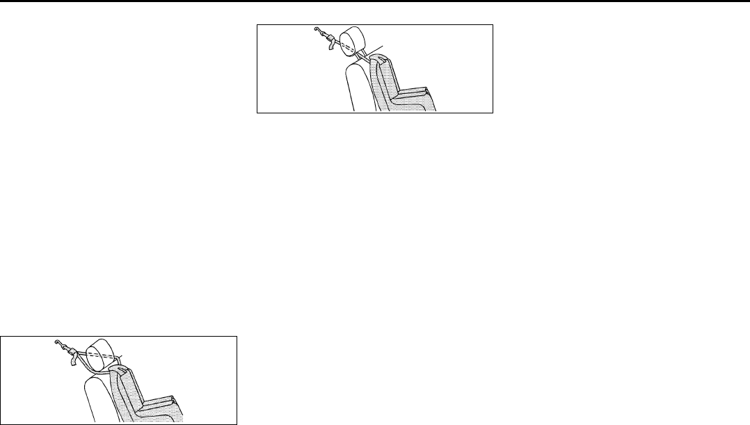
1549926
If the position you are using has an adjust-
able head restraint and you are using a
dual tether, route the tether around the
head restraint.
1549824
If the position you are using has an adjust-
able head restraint and you are using a
single tether, raise the head restraint and
route the tether under the head restraint
and in between the head restraint posts.
3) Push and pull the child restraint in dif-
ferent directions to be sure it is secure.
Securing a Child Restraint in a Rear
Seat Position
There is limited space in the third row rear
seating area. If you want to secure a child
restraint in a rear seating position in the
third row, be sure to study the instructions
that came with your child restraint to see if
there is enough room to secure your seat
properly. If the length of the seat cushion is
too short for your child restraint and you
cannot install it in accordance with the
child restraint manufacturers instructions,
secure it in the second row.
If your child restraint has the LATCH sys-
tem, refer to “Lower Anchors and Tethers
for Children (LATCH)” in this section.
There are no top tether anchors in the third
row seating positions. Do not secure a
child restraint in the third row if a national
or local law requires that a top tether be
anchored or if the instructions that come
with the restraint say that the top tether
must be anchored.
If your child restraint does not have the
LATCH system, you will be using the lap-
shoulder belt to secure the child restraint in
this position. Be sure to follow the instruc-
tions that came with the child restraint.
Secure the child in the child restraint when
and as the instructions say.
If you are using a rear-facing child restraint
in the second row center position, install
the armrest retention strap.
1) Put the child restraint on the seat.
2) Pick up the latch plate, and run the lap
and shoulder portions of the vehicle’s
safety belt through or around the
restraint. The child restraint instructions
will show you how.
1-30
SEATS AND RESTRAINT SYSTEMS
78J00-03E
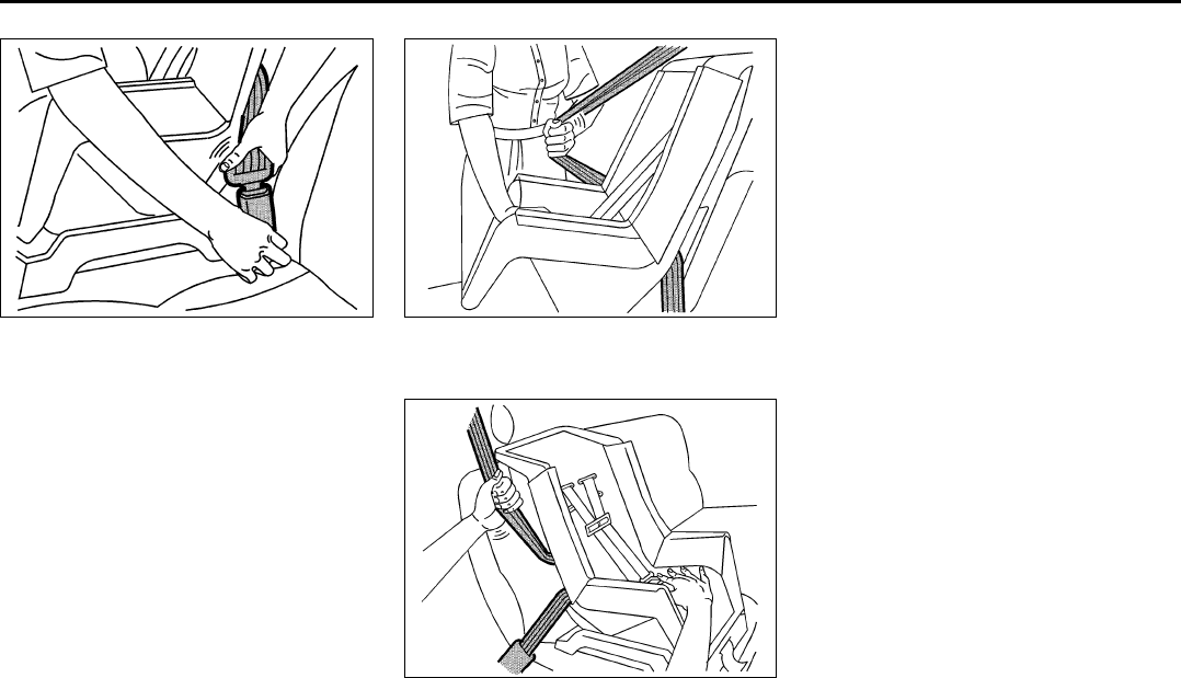
1379321
3) Buckle the belt. Make sure the release
button is positioned so you would be
able to unbuckle the safety belt quickly
if you ever had to.
1379324
4) Pull the rest of the shoulder belt all the
way out of the retractor to set the lock.
1379355
5) To tighten the belt, push down on the
child restraint, pull the shoulder portion
of the belt to tighten the lap portion of
the belt, and feed the shoulder belt
back into the retractor. If you are using
a forward-facing child restraint, you
may find it helpful to use your knee to
push down on the child restraint as you
tighten the belt.
6) If your child restraint has a top tether,
and the position that you are using has
a top tether anchor, attach and tighten
the top tether to the top tether anchor.
Refer to the instructions that came with
the child restraint and to “Lower
Anchors and Tethers for Children
(LATCH)” in this section.
7) Push and pull the child restraint in dif-
ferent directions to be sure it is secure.
To remove the child restraint, just unbuckle
the vehicle's safety belt and let it go back
all the way. The safety belt will move freely
again and be ready to work for an adult or
larger child passenger.
1-31
SEATS AND RESTRAINT SYSTEMS
78J00-03E
Securing a Child Restraint in the
Right Front Seat Position
Your vehicle has a right front passenger's
airbag. A rear seat is a safer place to
secure a forward-facing child restraint.
Refer to “Where to Put the Restraint” in
this section.
In addition, your vehicle has a passenger
sensing system. The passenger sensing
system is designed to turn off the right
front passenger’s frontal airbag when an
infant in a rear-facing infant seat or a small
child in a forward-facing child restraint or
booster seat is detected. Refer to “Passen-
ger Sensing System” in this section and
“Passenger Airbag Status Indicator” in
“Warning Lights, Gages, and Indicators” in
the “Instrument Panel” section for more
information on this including important
safety information.
A label on your sun visor says, “Never put
a rear-facing child seat in the front.” This is
because the risk to the rear-facing child is
so great, if the airbag deploys.
If your vehicle does not have a rear seat
that will accommodate a rear-facing child
restraint, never put a child in a rear-facing
child restraint in the right front passenger
seat unless the passenger airbag status
indicator shows off and the airbag is off.
Here is why:
If you need to secure a forward-facing
child restraint in the right front seat posi-
tion, move the seat as far back as it will go
before securing the forward-facing child
WARNING
A child in a rear-facing child restraint
can be seriously injured or killed if
the right front passenger's airbag
inflates. This is because the back of
the rear-facing child restraint would
be very close to the inflating airbag.
Even though the passenger sensing
system is designed to turn off the
right front passenger's frontal airbag
if the system detects a rear-facing
child restraint, no system is fail-safe,
and no one can guarantee that an air-
bag will not deploy under some
unusual circumstance, even though it
is turned off. We recommend that
rear-facing child restraints be
secured in the rear seat, even if the
airbag is off.
If you need to secure a forward-fac-
ing child restraint in the right front
seat, always move the front passen-
ger seat as far back as it will go. It is
better to secure the child restraint in
a rear seat.
WARNING
A child in a rear-facing child restraint
can be seriously injured or killed if
the right front passenger's airbag
inflates. This is because the back of
the rear-facing child restraint would
be very close to the inflating airbag.
Be sure the airbag is off before using
a rear-facing child restraint in the
right front seat position.
Even though the passenger sensing
system is designed to turn off the
passenger's frontal airbag if the sys-
tem detects a rear-facing child
restraint, no system is fail-safe, and
no one can guarantee that an airbag
will not deploy under some unusual
circumstance, even though it is
turned off. We recommend that rear-
facing child restraints be transported
in vehicles with a rear seat that will
accommodate a rear-facing child
restraint, whenever possible.
If you need to secure a forward-fac-
ing child restraint in the right front
seat, always move the front passen-
ger seat as far back as it will go. It is
better to secure the child restraint in
a rear seat.
1-32
SEATS AND RESTRAINT SYSTEMS
78J00-03E
restraint. Refer to “Manual Seats” in this
section.
If your child restraint has the LATCH sys-
tem, refer to “Lower Anchors and Tethers
for Children (LATCH)” in this section.
There is no top tether anchor at the right
front seating position. Do not secure a
child seat in this position if a national or
local law requires that the top tether be
anchored or if the instructions that come
with the child restraint say that the top
tether must be anchored. Refer to “Lower
Anchors and Tethers for Children
(LATCH)” in this section if the child
restraint has a top tether.
You will be using the lap-shoulder belt to
secure the child restraint in this position.
Be sure to follow the instructions that came
with the child restraint. Secure the child in
the child restraint when and as the instruc-
tions say.
1) Your vehicle has a right front passen-
ger’s frontal airbag. Refer to “Passen-
ger Sensing System” in this section. We
recommend that rear-facing child
restraints be secured in a rear seat,
even if the airbag is off. If your child
restraint is for ward-facing, move the
seat as far back as it will go before
securing the child restraint in this seat.
Refer to “Manual Seats” in this section.
When the passenger sensing system
has turned off the right front passen-
ger’s frontal airbag, the off indicator in
the passenger airbag status indicator
should light and stay lit when you turn
the ignition to RUN or START. Refer to
“Passenger Airbag Status Indicator” in
“Warning Lights, Gages, and Indica-
tors” in the “Instrument Panel” section.
2) Put the child restraint on the seat.
3) Pick up the latch plate, and run the lap
and shoulder portions of the vehicle’s
safety belt through or around the
restraint. The child restraint instructions
will show you how.
1379321
4) Buckle the belt. Make sure the release
button is positioned so you would be
able to unbuckle the safety belt quickly
if you ever had to.
1379324
5) Pull the rest of the shoulder belt all the
way out of the retractor to set the lock.
1379355
6) To tighten the belt, push down on the
child restraint, pull the shoulder portion
of the belt to tighten the lap portion of

1-33
SEATS AND RESTRAINT SYSTEMS
78J00-03E
the belt, and feed the shoulder belt
back into the retractor. If you are using
a forward-facing child restraint, you
may find it helpful to use your knee to
push down on the child restraint as you
tighten the belt. You should not be able
to pull more of the belt from the retrac-
tor once the lock has been set.
7) Push and pull the child restraint in dif-
ferent directions to be sure it is secure.
8) If the airbag is off, the off indicator on
the instrument panel will be lit and stay
lit when the key is turned to RUN or
START.
If a child restraint has been installed and
the on indicator is lit, turn the vehicle off.
Remove the child restraint from the vehicle
and reinstall the child restraint.
If, after reinstalling the child restraint and
restarting the vehicle, the on indicator is
still lit, check to make sure that the vehi-
cle’s seatback is not pressing the child
restraint into the seat cushion. If this hap-
pens, slightly recline the vehicle’s seatback
and adjust the seat cushion if possible.
Also make sure the child restraint is not
trapped under the vehicle head restraint. If
this happens, adjust the head restraint.
If the on indicator is still lit, secure the child
in the child restraint in a rear seat position
in the vehicle if one is available and check
with your dealer.
To remove the child restraint, if the top
tether is attached to the top tether anchor,
disconnect it. Unbuckle the vehicle’s safety
belt and let it go back all the way. The
safety belt will move freely again and be
ready to work for an adult or larger child
passenger.
Airbag System
Your vehicle has a frontal airbag for the
driver and a frontal airbag for the right front
passenger. Your vehicle also has roof-
mounted rollover airbags designed for
either side impact or rollover deployment.
Roof-mounted rollover airbags are avail-
able for the driver and the passenger
seated directly behind the driver and for
the right front passenger and the passen-
ger seated directly behind that passenger.
For roof-mounted rollover airbags, the
word AIRBAG will appear along the head-
liner or trim.
Also, if your vehicle has a third row pas-
senger seat, your vehicle will have third
row roof-mounted rollover airbags.
Airbags are designed to supplement the
protection provided by safety belts. Even
though today’s airbags are also designed
to help reduce the risk of injury from the
force of an inflating bag, all airbags must
inflate very quickly to do their job.
Here are the most important things to
know about the airbag system:
1-34
SEATS AND RESTRAINT SYSTEMS
78J00-03E
WARNING
You can be severely injured or killed
in a crash if you are not wearing your
safety belt – even if you have airbags.
Wearing your safety belt during a
crash helps reduce your chance of
hitting things inside the vehicle or
being ejected from it. Airbags are
“supplemental restraints” to the
safety belts. All airbags are designed
to work with safety belts but do not
replace them.
Frontal airbags for the driver and
right front passenger are designed to
deploy in moderate to severe frontal
and near frontal crashes. They are
not designed to inflate in rollover,
rear crashes, or in many side
crashes. And, for some unrestrained
occupants, frontal airbags may pro-
vide less protection in frontal
crashes than more forceful airbags
have provided in the past.
(Continued)
WARNING
(Continued)
Roof-mounted rollover airbags are
designed to inflate in moderate to
severe crashes where something hits
the side of your vehicle, during a
vehicle rollover, or in a severe frontal
impact. They are not designed to
inflate in rear crashes. If your vehicle
has roof-mounted airbags, they are
designed to provide both side impact
protection and rollover protection.
Everyone in your vehicle should wear
a safety belt properly – whether or
not there is an airbag for that person.
WARNING
Both frontal and roof-mounted roll-
over airbags inflate with great force,
faster than the blink of an eye. If you
are too close to an inflating airbag, as
you would be if you were leaning for-
ward, it could seriously injure you.
Safety belts help keep you in position
for airbag inflation before and during
a crash. Always wear your safety belt
even with frontal airbags. The driver
should sit as far back as possible
while still maintaining control of the
vehicle. Occupants should not lean
on or sleep against the door in the
first or second row seats, or the rear
windows in the third row seat, if your
vehicle has roof-mounted rollover air-
bags.
1-35
SEATS AND RESTRAINT SYSTEMS
78J00-03E
808302
There is an airbag readiness light on the
instrument panel cluster, which shows the
airbag symbol.
The system checks the airbag electrical
system for malfunctions. The light tells you
if there is an electrical problem. Refer to
“Airbag Readiness Light” in “Warning
Lights, Gages, and Indicators” in the
“Instrument Panel” section for more infor-
mation.
Where Are the Airbags?
1177656
The driver’s airbag is in the middle of the
steering wheel.
809967
The right front passenger’s airbag is in the
instrument panel on the passenger’s side.
WARNING
Anyone who is up against, or very
close to, any airbag when it inflates
can be seriously injured or killed. Air-
bags plus lap-shoulder belts offer the
best protection for adults, but not for
young children and infants. Neither
the vehicle’s safety belt system nor
its airbag system is designed for
them. Young children and infants
need the protection that a child
restraint system can provide. Always
secure children properly in your vehi-
cle. To read how, refer to “Older Chil-
dren” or “Infants and Young
Children” in this section.
Occupants should not lean on or
sleep against the door in the first or
second row seats, or the rear win-
dows in the third row seat, if your
vehicle has roof-mounted rollover
airbags.
1-36
SEATS AND RESTRAINT SYSTEMS
78J00-03E
1177533
The roof-mounted rollover airbag for the
driver and the person seated directly
behind the driver is located in the ceiling
above the side windows.
1197154
The roof-mounted rollover airbag for the
right front passenger and the person
directly behind that passenger is located in
the ceiling above the side windows.
1700418
If your vehicle has a third row seat, the
roof-mounted rollover airbag is located in
the ceiling above the rear windows for the
outside passenger positions.

1-37
SEATS AND RESTRAINT SYSTEMS
78J00-03E
When Should an Airbag Inflate?
The driver’s and right front passenger’s
frontal airbags are designed to inflate in
moderate to severe frontal or near-frontal
crashes. But they are designed to inflate
only if the impact exceeds a predetermined
deployment threshold. Deployment thresh-
olds take into account a variety of desired
deployment and non-deployment events
and are used to predict how severe a crash
is likely to be in time for the airbags to
inflate and help restrain the occupants.
Whether your frontal airbags will or should
deploy is not based on how fast your vehi-
cle is traveling. It depends largely on what
you hit, the direction of the impact and how
quickly your vehicle slows down.
In addition, your vehicle has “dual-stage”
frontal airbags, which adjust the restraint
according to crash severity. Your vehicle
has electronic frontal sensors which help
the sensing system distinguish between a
moderate frontal impact and a more severe
frontal impact. For moderate frontal
impacts, these airbags inflate at a level
less than full deployment. For more severe
frontal impacts, full deployment occurs. If
the front of your vehicle goes straight into a
wall that does not move or deform, the
threshold level for the reduced deployment
is about 11 to 16 mph (17 to 26 km/h), and
the threshold level for a full deployment is
about 20 to 25 mph (32 to 40 km/h). The
threshold level can vary, however, with
specific vehicle design, so that it can be
somewhat above or below this range.
Frontal airbags may inflate at different
crash speeds. For example:
• If the vehicle hits a stationary object, the
airbags could inflate at a different crash
speed than if the vehicle hits a moving
object.
• If the vehicle hits an object that deforms,
the airbags could inflate at a different
crash speed than if the vehicle hits an
object that does not deform.
• If the vehicle hits a narrow object (like a
pole) the airbags could inflate at a differ-
ent crash speed than if the vehicle hits a
wide object (like a wall).
• If the vehicle goes into an object at an
angle the airbags could inflate at a differ-
ent crash speed than if the vehicle goes
straight into the object.
The frontal airbags (driver and right front
passenger) are not intended to inflate dur-
ing vehicle rollovers, rear impacts, or in
many side impacts.
Your vehicle has roof-mounted rollover air-
bags and a rollover sensor. Refer to “Air-
bag System” in this section. These
“rollover capable” airbags are intended to
inflate in moderate to severe side crashes,
during a rollover or in a severe frontal
impact. A roof-mounted rollover airbag will
inflate if the crash severity is above the
system’s designed “threshold level.” The
threshold level can vary with specific vehi-
cle design. Roof-mounted rollover airbags
are not intended to inflate in rear impacts.
Both roof-mounted rollover airbags will
deploy when either side of the vehicle is
struck or during a rollover, or in a severe
frontal impact.
In any particular crash, no one can say
whether an airbag should have inflated
simply because of the damage to a vehicle
or because of what the repair costs were.
For frontal airbags, inflation is determined
by what the vehicle hits, the angle of the
WARNING
If something is between an occupant
and an airbag, the bag might not
inflate properly or it might force the
object into that person causing
severe injury or even death. The path
of an inflating airbag must be kept
clear. Do not put anything between
an occupant and an airbag, and do
not attach or put anything on the
steering wheel hub or on or near any
other airbag covering. And, if your
vehicle has roof-mounted rollover
airbags, never secure anything to the
roof of your vehicle by routing the
rope or tie down through any door or
window opening. If you do, the path
of an inflating side impact airbag will
be blocked. The path of an inflating
airbag must be kept clear.

1-38
SEATS AND RESTRAINT SYSTEMS
78J00-03E
impact, and how quickly the vehicle slows
down. For roof-mounted rollover airbags,
inflation is determined by the location and
severity of the impact or a rollover event.
What Makes an Airbag Inflate?
In an impact of sufficient severity, the air-
bag sensing system detects that the vehi-
cle is in a crash. In the case of a roof-
mounted rollover airbag, the sensing sys-
tem detects that the vehicle is about to roll
over or has been in a severe frontal or side
impact. The sensing system triggers a
release of gas from the inflator, which
inflates the airbag. The inflator, airbag, and
related hardware are all part of the airbag
modules inside the steering wheel and in
the instrument panel in front of the right
front passenger. For vehicles with roof-
mounted rollover airbags, the airbag mod-
ules are located in the ceiling of the vehi-
cle, near the side windows.
If your vehicle has a third row seat with
roof-mounted rollover airbags, the airbag
modules are located inside the rear-most
pillar trim and above in the ceiling above
the fixed rear glass.
How Does an Airbag Restrain?
In moderate to severe frontal or near fron-
tal collisions, even belted occupants can
contact the steering wheel or the instru-
ment panel. In moderate to severe side
collisions, even belted occupants can con-
tact the inside of the vehicle. Airbags sup-
plement the protection provided by safety
belts. Airbags distribute the force of the
impact more evenly over the occupant's
upper body, stopping the occupant more
gradually. But the frontal airbags would not
help you in many types of collisions,
including rollovers, rear impacts, and many
side impacts, primarily because an occu-
pant's motion is not toward the airbag.
Roof-mounted rollover airbags would not
help you in many types of collisions,
including many frontal or near frontal colli-
sions, and rear impacts.
Airbags should never be regarded as any-
thing more than a supplement to safety
belts, and then only in moderate to severe
frontal or near-frontal collisions for the
driver's and right front passenger’s frontal
airbags, and only in moderate to severe
side collisions or rollovers for vehicles with
roof-mounted rollover airbags.
What Will You See After an Airbag
Inflates?
After a frontal airbag inflates, it quickly
deflates, so quickly that some people may
not even realize an airbag inflated. Roof-
mounted rollover airbags may still be at
least partially inflated minutes after the
vehicle comes to rest. Some components
of the airbag module – the steering wheel
hub for the driver's airbag, the instrument
panel for the right front passenger's airbag,
and the area along the ceiling of the vehi-
cle near the side windows for vehicles with
roof-mounted side impact airbags – may
be hot for a short time. The parts of the air-
bag that come into contact with you may
be warm, but not too hot to touch. There
may be some smoke and dust coming from
the vents in the deflated airbags. Airbag
inflation does not prevent the driver from
seeing out of the windshield or being able
to steer the vehicle, nor does it prevent
people from leaving the vehicle.
Your vehicle has a feature that may auto-
matically unlock the doors, turn the interior
lamps on, and flash the hazard warning
flashers when the airbags inflate. You can
lock the doors again, turn the interior
lamps off, and turn off the hazard warning
flashers by using the controls for those
features.
WARNING
When an airbag inflates, there may be
dust in the air. This dust could cause
breathing problems for people with a
history of asthma or other breathing
trouble. To avoid this, everyone in the
vehicle should get out as soon as it is
safe to do so. If you have breathing
problems but cannot get out of the
vehicle after an airbag inflates, then
get fresh air by opening a window or
a door. If you experience breathing
problems following an airbag deploy-
ment, you should seek medical atten-
tion.

1-39
SEATS AND RESTRAINT SYSTEMS
78J00-03E
In many crashes severe enough to inflate
the airbag, windshields are broken by vehi-
cle deformation. Additional windshield
breakage may also occur from the right
front passenger airbag.
• Airbags are designed to inflate only
once. After an airbag inflates, you will
need some new parts for your airbag
system. If you do not get them, the air-
bag system will not be there to help pro-
tect you in another crash. A new system
will include airbag modules and possibly
other parts. The service manual for your
vehicle covers the need to replace other
parts.
• Your vehicle has a crash sensing and
diagnostic module which records infor-
mation after a crash.
• Let only qualified technicians work on
the airbag system. Improper service can
mean that an airbag system will not work
properly. See your dealer for service.
Passenger Sensing System
Your vehicle has a passenger sensing sys-
tem for the right front passenger. The pas-
senger airbag status indicator will be
visible when you start your vehicle in the
instrument panel.
United States
1476572
Canada
1476529
The words ON and OFF, or the symbol for
on and off, will be visible during the system
check. When the system check is com-
plete, either the word ON or the word OFF,
or the symbol for on or the symbol for off,
will be visible. Refer to “Passenger Airbag
Status Indicator” in “Warning Lights,
Gages, and Indicators” in the “Instrument
Panel” section.
The passenger sensing system will turn off
the right front passenger’s frontal airbag
under certain conditions. The driver’s air-
bags are not part of the passenger sensing
system.
The passenger sensing system works with
sensors that are part of the right front pas-
senger’s seat and safety belt. The sensors
are designed to detect the presence of a
properly seated occupant and determine if
the passenger’s frontal airbag should be
enabled (may inflate) or not.
Accident statistics show that children are
safer if they are restrained in the rear
rather than the front seat. We recommend
that child restraints be secured in a rear
seat, including an infant riding in a rear-
facing infant seat, a child riding in a for-
ward-facing child seat, and an older child
riding in a booster seat.
There is a label on your sun visor that
says, “Never put a rear-facing child seat in
the front.” This is because the risk to the
rear-facing child is so great, if the airbag
deploys.
1-40
SEATS AND RESTRAINT SYSTEMS
78J00-03E
If your vehicle does not have a rear seat
that will accommodate a rear-facing child
restraint, never put a child in a rear-facing
child restraint in the right front passenger
seat unless the passenger airbag status
indicator shows off and the airbag is off.
Here is why:
The passenger sensing system is
designed to turn off the right front passen-
ger’s frontal airbag if:
• The right front passenger seat is unoc-
cupied.
• The system determines that an infant is
present in a rear-facing infant seat.
• The system determines that a small child
is present in a forward-facing child
restraint.
• The system determines that a small child
is present in a booster seat.
• A right front passenger takes his/her
weight off of the seat for a period of time.
• The right front passenger seat is occu-
pied by a smaller person, such as a child
who has outgrown child restraints.
• Or, if there is a critical problem with the
airbag system or the passenger sensing
system.
When the right front passenger’s frontal
airbag has been turned off by the passen-
ger sensing system, the off indicator will
light and stay lit to remind you that the air-
bag is off.
If a child restraint has been installed and
the on indicator is lit, turn the vehicle off.
Remove the child restraint from the vehicle
and reinstall the child restraint following the
child restraint manufacturer’s directions
and refer to “Securing a Child Restraint in
the Right Front Seat Position” in this sec-
tion.
WARNING
A child in a rear-facing child restraint
can be seriously injured or killed if
the right front passenger’s airbag
inflates. This is because the back of
the rear-facing child restraint would
be very close to the inflating airbag.
Even though the passenger sensing
system is designed to turn off the
passenger’s frontal airbag if the sys-
tem detects a rear-facing child
restraint, no system is fail-safe, and
no one can guarantee that an airbag
will not deploy under some unusual
circumstance, even though it is
turned off. We recommend that rear-
facing child restraints be secured in
the rear seat, even if the airbag is off.
If you need to secure a forward-fac-
ing child restraint in the right front
seat, always move the front passen-
ger seat as far back as it will go. It is
better to secure the child restraint in
a rear seat.
WARNING
A child in a rear-facing child restraint
can be seriously injured or killed if
the right front passenger’s airbag
inflates. This is because the back of
the rear-facing child restraint would
be very close to the inflating airbag.
Be sure the airbag is off before using
a rear-facing child restraint in the
right front seat position.
Even though the passenger sensing
system is designed to turn off the
passenger’s frontal airbag if the sys-
tem detects a rear-facing child
restraint, no system is fail-safe, and
no one can guarantee that an airbag
will not deploy under some unusual
circumstance, even though it is
turned off. We recommend that rear-
facing child restraints be trans-
ported in vehicles with a rear seat
that will accommodate a rear-facing
child restraint, whenever possible.
If you need to secure a forward-fac-
ing child restraint in the right front
seat, always move the front passen-
ger seat as far back as it will go. It is
better to secure the child restraint in
a rear seat.
1-41
SEATS AND RESTRAINT SYSTEMS
78J00-03E
If, after reinstalling the child restraint and
restarting the vehicle, the on indicator is
still lit, check to make sure that the vehi-
cle’s seatback is not pressing the child
restraint into the seat cushion. If this hap-
pens, slightly recline the vehicle’s seatback
and adjust the seat cushion if possible.
Also make sure the child restraint is not
trapped under the vehicle head restraint. If
this happens, adjust the head restraint.
If the on indicator is still lit, secure the child
in the child restraint in a rear seat position
in the vehicle if one is available and check
with your dealer.
The passenger sensing system is
designed to enable (may inflate) the right
front passenger’s frontal airbag anytime
the system senses that a person of adult
size is sitting properly in the right front pas-
senger’s seat. When the passenger sens-
ing system has allowed the airbag to be
enabled, the on indicator will light and stay
lit to remind you that the airbag is active.
For some children who have outgrown
child restraints and for very small adults,
the passenger sensing system may or may
not turn off the right front passenger’s fron-
tal airbag, depending upon the person’s
seating posture and body build. Everyone
in your vehicle who has outgrown child
restraints should wear a safety belt prop-
erly – whether or not there is an airbag for
that person.
If a person of adult-size is sitting in the
right front passenger’s seat, but the off
indicator is lit, it could be because that per-
son is not sitting properly in the seat. If this
happens, turn the vehicle off and ask the
person to place the seatback in the fully
upright position, then sit upright in the seat,
centered on the seat cushion, with the per-
son’s legs comfortably extended. Restart
the vehicle and have the person remain in
this position for about two minutes. This
will allow the system to detect that person
and then enable the passenger’s airbag.
849515
A thick layer of additional material, such as
a blanket, or aftermarket equipment such
as seat covers, seat heaters, and seat
massagers, can affect how well the pas-
senger sensing system operates. Remove
any additional material from the seat cush-
ion before reinstalling or securing the child
restraint and before a small occupant,
including a small adult, sits in the passen-
ger position. You may want to consider not
using seat covers or other aftermarket
equipment. Refer to “Adding Equipment to
Your Airbag-Equipped Vehicle” in this sec-
tion for more information about modifica-
tions that can affect how the system
operates.
WARNING
If the airbag readiness light in the
instrument panel cluster ever comes
on and stays on, it means that some-
thing may be wrong with the airbag
system. If this ever happens, have
the vehicle serviced promptly,
because an adult-size person sitting
in the right front passenger’s seat
may not have the protection of the
frontal airbag. Refer to “Airbag
Readiness Light” in “Warning Lights,
Gages, and Indicators” in the “Instru-
ment Panel” section for more on this,
including important safety informa-
tion.

1-42
SEATS AND RESTRAINT SYSTEMS
78J00-03E
Servicing Your Airbag-Equipped
Vehicle
Airbags affect how your vehicle should be
serviced. There are parts of the airbag
system in several places around your vehi-
cle. You do not want the system to inflate
while someone is working on your vehicle.
Your dealer and the service manual have
information about servicing your vehicle
and the airbag system.
The airbag system does not need regular
maintenance.
Adding Equipment to Your Airbag-
Equipped Vehicle
Question:
Is there anything I might add to the front
or sides of the vehicle that could keep
the airbags from working properly?
Answer:
Yes. If you add things that change your
vehicle’s frame, bumper system, height,
front end or side sheet metal, they may
keep the airbag system from working prop-
erly. Also, the airbag system may not work
properly if you relocate any of the airbag
sensors. If you have any questions about
this, you should contact Customer Assis-
tance before you modify your vehicle.
Question:
Because I have a disability, I have to get
my vehicle modified. How can I find out
whether this will affect my airbag sys-
tem?
Answer:
Changing or moving any parts of the front
seats, safety belts, the airbag sensing and
diagnostic module, rollover sensor module,
steering wheel, instrument panel, over-
head console, ceiling headliner, ceiling
and pillar garnish trim, roof-mounted roll-
over airbag modules, or airbag wiring can
affect the operation of the airbag system. If
you have questions, call Customer Assis-
tance.
Restraint System Check
Checking the Restraint Systems
Now and then, make sure the safety belt
reminder light and all your belts, buckles,
latch plates, retractors and anchorages are
working properly. Look for any other loose
or damaged safety belt system parts. If you
see anything that might keep a safety belt
system from doing its job, have it repaired.
Keep safety belts clean and dry. Refer to
“Care of Safety Belts” in “Appearance
Care” in the “Service and Appearance
Care” section for more information.
Torn or frayed safety belts may not protect
you in a crash. They can rip apart under
impact forces. If a belt is torn or frayed, get
a new one right away.
Also look for any opened or broken airbag
covers, and have them repaired or
replaced. The airbag system does not
need regular maintenance.
WARNING
Stowing of articles under the passen-
ger’s seat or between the passen-
ger’s seat cushion and seatback may
interfere with the proper operation of
the passenger sensing system.
WARNING
For up to 10 seconds, after the igni-
tion is turned off and the battery is
disconnected, an airbag can still
inflate during improper service. You
can be injured if you are close to an
airbag when it inflates. Avoid yellow
connectors. They are probably part of
the airbag system. Be sure to follow
proper service procedures, and make
sure the person performing work for
you is qualified to do so.

1-43
SEATS AND RESTRAINT SYSTEMS
78J00-03E
Replacing Restraint System Parts
After a Crash
If you have had a crash, do you need new
belts or LATCH system parts?
After a very minor collision, nothing may be
necessary. But if the belts were stretched,
as they would be if worn during a more
severe crash, then you need new parts.
If the LATCH system was being used dur-
ing a more severe crash, you may need
new LATCH system parts.
If belts are cut or damaged, replace them.
Collision damage also may mean you will
need to have LATCH system, safety belt or
seat parts repaired or replaced. New parts
and repairs may be necessary even if the
belt or LATCH system was not being used
at the time of the collision.
If an airbag inflates, you will need to
replace airbag system parts. See the part
on the airbag system earlier in this section.
If the frontal airbags inflate you will also
need to replace the driver and front pas-
senger’s safety belt retractor assembly. Be
sure to do so. Then the new retractor
assembly will be there to help protect you
in a collision.
After a crash you may need to replace the
driver and front passenger’s safety belt
retractor assemblies, even if the frontal air-
bags have not deployed. The driver and
front passenger’s safety belt retractor
assemblies contain the safety belt preten-
sioners. Have your safety belt pretension-
ers checked if your vehicle has been in a
collision, or if your airbag readiness light
stays on after you start your vehicle or
while you are driving. Refer to “Airbag
Readiness Light” in “Warning Lights,
Gages, and Indicators” in the “Instrument
Panel” section.
CAUTION
If you damage the covering for the
driver’s or the right front passenger’s
airbag, or the side impact airbag cov-
ering on the ceiling near the side win-
dows, the airbag may not work
properly. You may have to replace the
airbag module in the steering wheel,
both the airbag module and the
instrument panel for the right front
passenger’s airbag, or side impact
airbag module and ceiling covering
for roof-mounted rollover airbags. Do
not open or break the airbag cover-
ings.
WARNING
A crash can damage the restraint
systems in your vehicle. A damaged
restraint system may not properly
protect the person using it, resulting
in serious injury or even death in a
crash. To help make sure your
restraint systems are working prop-
erly after a crash, have them
inspected and any necessary
replacements made as soon as pos-
sible.

FEATURES AND CONTROLS
2
78J00-03E
FEATURES AND CONTROLS
Keys ...................................................................................... 2-1
Doors and Locks ................................................................. 2-5
Windows .............................................................................. 2-8
Theft-Deterrent Systems .................................................... 2-9
Daily Inspection Checklist .................................................. 2-11
Starting and Operating Your Vehicle ................................ 2-12
Mirrors .................................................................................. 2-20
Storage Areas ...................................................................... 2-21
Sunroof ................................................................................ 2-24
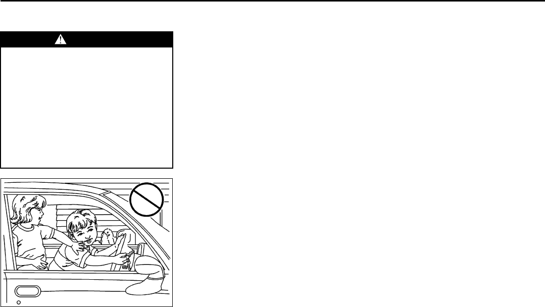
2-1
FEATURES AND CONTROLS
78J00-03E
Keys
805686
One key is used for the ignition and all of
the locks.
Key code information can be obtained by
your dealer. These code numbers can be
used to make new keys. Additional keys
that are needed can be made at any retail
service facility provided you have the key
code information. Store this information in
a safe place, but not in your vehicle.
Have extra keys made. Your service parts
department can make extra keys for you.
NOTE:
If you ever lock your keys in your vehicle,
you may have to damage the vehicle to get
in. Be sure you have spare keys.
Remote Keyless Entry (RKE)
System
The remote keyless entry system operates
on a radio frequency subject to Federal
Communications Commission (FCC)
Rules and with Industry Canada.
This device complies with Part 15 of the
FCC Rules. Operation is subject to the fol-
lowing two conditions:
• This device may not cause harmful inter-
ference.
• This device must accept any interfer-
ence received, including interference
that may cause undesired operation of
the device.
This device complies with RSS-210 of
Industry Canada. Operation is subject to
the following two conditions:
• This device may not cause interference.
• This device must accept any interfer-
ence received, including interference
that may cause undesired operation of
the device.
Changes or modifications to this system by
other than an authorized service facility
could void authorization to use this equip-
ment.
At times you may notice a decrease in
range. This is normal for any remote key-
less entry system. If the transmitter does
not work or if you have to stand closer to
your vehicle for the transmitter to work, try
this:
• Check the distance. You may be too far
from your vehicle. You may need to
stand closer during rainy or snowy
weather.
• Check the location. Other vehicles or
objects may be blocking the signal. Take
a few steps to the left or right, hold the
transmitter higher, and try again.
• Check to determine if battery replace-
ment or resynchronization is necessary.
Refer to “Battery Replacement” and
“Resynchronization” under “Remote
Keyless Entry (RKE) System Operation”
in this section.
• If you are still having trouble, see your
dealer or a qualified technician for ser-
vice.
WARNING
Leaving children in a vehicle with the
ignition key is dangerous for many
reasons, children or others could be
badly injured or even killed. They
could operate the power windows or
other controls or even make the vehi-
cle move. The windows will function
with the keys in the ignition and they
could be seriously injured or killed if
caught in the path of a closing win-
dow. Do not leave the keys in a vehi-
cle with children.
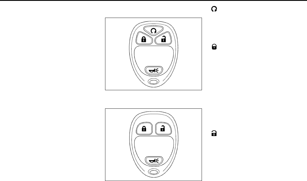
2-2
FEATURES AND CONTROLS
78J00-03E
Remote Keyless Entry (RKE)
System Operation
The vehicle’s doors can be locked and
unlocked from about 3 feet (1 m) up to 65
feet (20 m) away with the Remote Keyless
Entry (RKE) transmitter.
If your vehicle has the remote start feature
you can also start your vehicle with the
RKE transmitter. Your RKE transmitter,
with the remote start button, provides an
increased range of 195 feet (60 m) away.
However, the range may be less while the
vehicle is running. As a result, you may
need to be closer to your vehicle to turn it
off than you were to turn it on.
There are other conditions which can
affect the performance of the transmitter.
Refer to “Remote Keyless Entry (RKE)
System” in this section.
Remote Keyless Entry with
Remote Start
1686604
Remote Keyless Entry without Remote
Start
1686606
The following functions may be available if
your vehicle has the RKE system:
(Remote Vehicle Start):
If your vehicle has this feature, it may be
started from outside the vehicle using the
RKE transmitter. See “Remote Vehicle
Start” following, for more detailed informa-
tion.
(Lock):
Press the lock button to lock the doors and
liftgate. If enabled through the Driver Infor-
mation Center (DIC), the parking lamps will
flash once to indicate locking has
occurred. If enabled through the DIC, the
horn will chirp when the lock button is
pressed again within five seconds of the
previous press of the lock button. Refer to
“DIC Vehicle Personalization” in “Driver
Information Center (DIC)” in the “Instru-
ment Panel” section for additional informa-
tion. Pressing the lock button may arm the
content theft-deterrent system. Refer to
“Content Theft-Deterrent” in this section.
(Unlock):
Press the unlock button to unlock the
driver's door. If the button is pressed again
within five seconds, all remaining doors,
and the liftgate, will unlock. The interior
lamps will come on and stay on for 20 sec-
onds or until the ignition is turned on. If
enabled through the DIC, the parking
lamps will flash once to indicate unlocking
has occurred. Refer to “DIC Vehicle Per-
sonalization” in “Driver Information Center
(DIC)” in the “Instrument Panel” section.
Pressing the unlock button on the RKE
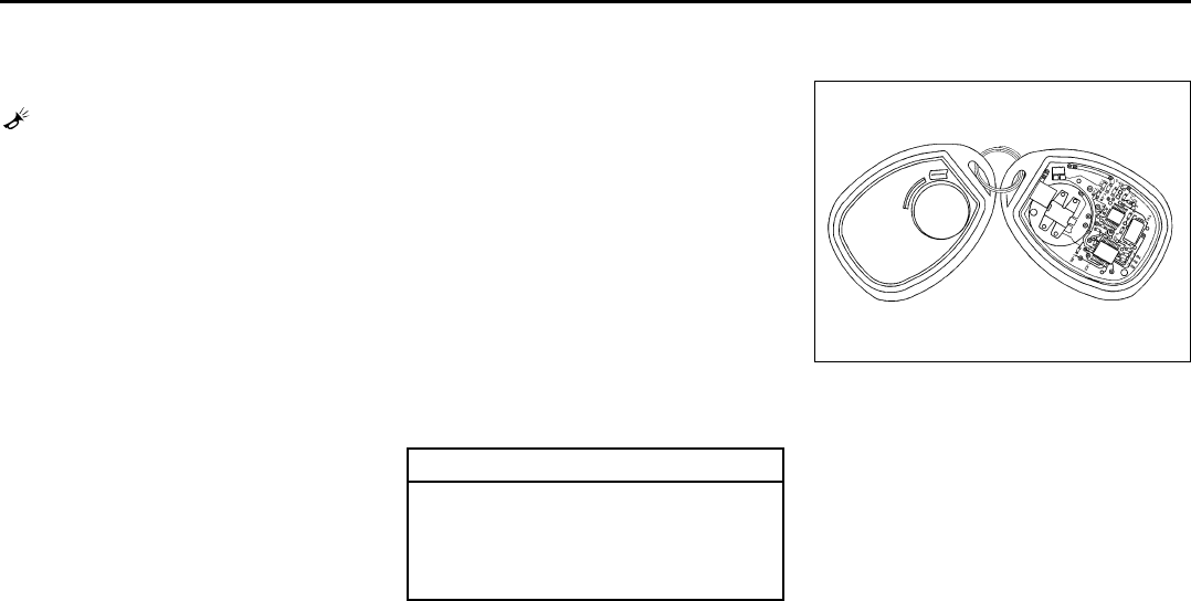
2-3
FEATURES AND CONTROLS
78J00-03E
transmitter will disarm the content theft-
deterrent system. Refer to “Content Theft-
Deterrent” in this section.
(Vehicle Locator/Panic Alarm):
Press and release this button to locate
your vehicle. The turn signal lamps will
flash and the horn will sound three times.
Press and hold this button for more than
two seconds to activate the panic alarm.
The turn signal lamps will flash and the
horn will sound repeatedly for 30 seconds.
The alarm will turn off when the ignition is
moved to RUN or the alarm button is
pressed again. The ignition must be in
LOCK for the panic alarm to work.
The RKE transmitter is used to arm/disarm
the content theft-deterrent system. Your
vehicle’s theft-deterrent system can be
programmed to three different modes.
Refer to “Content Theft-Deterrent” in this
section.
If you accidentally set off the alarm when
entering or exiting the vehicle, you can
shut it off by pressing the lock or unlock
button once or the panic alarm button
twice.
Matching Transmitter(s) to Your Vehicle
Each RKE transmitter is coded to prevent
another transmitter from unlocking your
vehicle. If a transmitter is lost or stolen, a
replacement can be purchased through
your dealer. Remember to bring any addi-
tional transmitters so they can also be re-
coded to match the new transmitter. Once
your dealer has coded the new transmitter,
the lost transmitter will not unlock your
vehicle. The vehicle can have a maximum
of four transmitters matched to it. Or, refer
to “Relearn Remote Key” under “DIC Oper-
ation and Displays” in “Driver Information
Center (DIC)” in the “Instrument Panel”
section for instructions on how to match
RKE transmitters to your vehicle.
Battery Replacement
Under normal use, the battery in your RKE
transmitter should last about four years.
The battery is weak if the transmitter will
not work at the normal range in any loca-
tion. If you have to get close to your vehi-
cle before the transmitter works, it is
probably time to change the battery.
To replace the battery in the RKE transmit-
ter, do the following:
1) Use a flat thin object to pry open the
transmitter.
1562525
2) Once the transmitter is separated, use
a pencil or similar object to remove the
old battery. Do not use a metal object.
3) Slide the new battery into the transmit-
ter with the positive side of the battery
facing down. Use a type CR2032 bat-
tery, or equivalent type.
4) Snap the transmitter back together
tightly to be sure no moisture can enter.
5) Check the operation of the transmitter.
CAUTION
When replacing the battery, use care
not to touch any of the circuitry.
Static from your body transferred to
these surfaces may damage the
transmitter.

2-4
FEATURES AND CONTROLS
78J00-03E
Remote Vehicle Start
Your vehicle may have the remote start
feature. This feature allows you to start the
engine from outside the vehicle. Refer to
“REMOTE START” under “DIC Vehicle
Personalization” in “Driver Information
Center (DIC)” in the “Instrument Panel”
section for instructions on how to enable
and disable this feature.
During a remote start, the climate control
system will turn on at the fan, temperature,
and mode settings the vehicle was set to
when the vehicle was last turned off and
will also turn on the rear window defogger.
Laws in some local communities may
restrict the use of remote starters. For
example, some laws may require a person
using remote start to have the vehicle in
view when doing so. Check local regula-
tions for any requirements on remote start-
ing of vehicles.
(Remote Vehicle Start):
Press and release the lock button and then
press and hold the remote start button to
start the vehicle.
Your RKE transmitter, with the remote start
button, provides an increased range of
operation. However, the range may be less
while the vehicle is running. As a result,
you may need to be closer to your vehicle
to turn it off, than you were to turn it on.
If your vehicle is low on fuel, do not use the
remote start feature. The vehicle may run
out of fuel.
To start the engine using the remote start
feature, do the following:
1) Aim the RKE transmitter, that has a
remote vehicle start button, at the vehi-
cle.
2) Press and release the transmitter’s lock
button, then immediately press and
hold the remote vehicle start button
until the vehicle’s turn signal lamps
flash, or for at least four seconds, if the
vehicle’s lights are not visible. The vehi-
cle’s doors will be locked. Pressing the
remote start button again after the vehi-
cle has started will turn off the ignition.
3) When the vehicle’s engine starts, the
parking lamps will turn on and remain
on while the engine is running.
4) If it is your first remote start since last
driving, repeat these steps while the
engine is still running for a 10 minute
time extension.
When you enter the vehicle during a
remote start, and the engine is still running,
turn the key to the RUN position to drive
the vehicle
.
After a remote start, the engine will auto-
matically shut off after 10 minutes unless a
time extension has been done or the vehi-
cle’s key is inserted into the ignition switch
and turned to RUN.
The maximum number of remote starts or
remote start attempts between ignition
cycles with the key is two.
If the remote start procedure is used again
before the first 10 minute time frame has
ended, the first 10 minutes will immediately
expire and the second 10 minute time
frame will start.
For example, if the lock button and then
the remote start buttons are pressed again
after the vehicle has been running for five
minutes, 10 minutes are added, allowing
the engine to run for 15 minutes.
After your vehicle’s engine has been
started two times using the remote vehicle
start button, the vehicle’s ignition switch
must be turned to RUN and then back to
LOCK using the key before the remote
start procedure can be used again.
If you enter the vehicle after a remote start,
and the engine is running, insert the key
into the ignition switch and turn it to the
RUN position to drive the vehicle.
To manually shut off the engine after a
remote start, do any of the following:
• Aim the RKE transmitter at the vehicle
and press the remote start button until
the parking lamps turn off.
• Turn on the hazard warning flashers.
• Insert the vehicle’s key into the ignition
switch and turn the switch to RUN and
then back to LOCK.
2-5
FEATURES AND CONTROLS
78J00-03E
The remote vehicle start feature will not
operate if:
• The vehicle’s key is in the ignition.
• The vehicle’s hood, liftgate or doors are
not closed.
• The hazard warning flashers are on.
• There is an emission control system
malfunction.
• The engine coolant temperature is too
high.
• The oil pressure is low.
• Two remote vehicle starts have already
been used. The maximum number of
remote starts or remote start attempts
between ignition cycles with the key is
two.
Vehicles that have the remote vehicle start
feature are shipped from the factory with
the remote vehicle start system enabled.
The system may be enabled or disabled
through the DIC. Refer to “REMOTE
START” under “DIC Vehicle Personaliza-
tion” in “Driver Information Center (DIC)” in
the “Instrument Panel” section for addi-
tional information.
Doors and Locks
Door Locks
There are a couple of ways to manually
lock or unlock your vehicle.
From the outside, use the key in the
driver’s door.
From the inside, use the lock control on the
door.
Power Door Locks
The power door lock switches are located
on the driver’s and front passenger’s
doors.
(Unlock):
To unlock the doors, press the unlock sym-
bol.
(Lock):
Remove the ignition key and press the lock
symbol to lock all of the doors.
WARNING
Unlocked doors can be dangerous.
• Passengers, especially children,
can easily open the doors and fall
out of a moving vehicle. When a
door is locked, the handle will not
open it. You increase the chance of
being thrown out of the vehicle in a
crash if the doors are not locked.
So, wear safety belts properly and
lock the doors whenever you drive.
• Young children who get into
unlocked vehicles may be unable
to get out. A child can be overcome
by extreme heat and can suffer per-
manent injuries or even death from
heat stroke. Always lock your vehi-
cle whenever you leave it.
• Outsiders can easily enter through
an unlocked door when you slow
down or stop your vehicle. Locking
your doors can help prevent this
from happening.

2-6
FEATURES AND CONTROLS
78J00-03E
Delayed Locking
A chime will sound three times to indicate
a door or liftgate is open when you try to
lock the doors with the remote keyless
entry (RKE) transmitter or the power door
lock switch. The doors will not lock, and
the theft-deterrent system will not arm until
all the doors are closed and ten seconds
have passed.
The delayed locking feature can be pro-
grammed through the Driver Information
Center (DIC). Refer to “DIC Vehicle Per-
sonalization” in “Driver Information Center
(DIC)” in the “Instrument Panel” section.
Programmable Automatic Door
Locks
Your vehicle has an automatic lock/unlock
feature which enables you to program the
power door locks through the Driver Infor-
mation Center (DIC). Refer to “DIC Vehicle
Personalization” in “Driver Information
Center (DIC)” in the “Instrument Panel”
section for more information on DIC pro-
gramming.
Rear Door Security Locks
Your vehicle has rear door security locks
that prevent passengers from opening the
rear doors from the inside.
831642
The rear door security locks are located on
the inside edge of each rear door. You
must open the rear doors to access them.
To set the security locks, do the following:
1) Insert the key into the lock above the
rear door security lock label and turn it
to the horizontal position.
2) Close the door.
3) Repeat the steps for the other rear
door.
To open a rear door while the security lock
is on, do the following:
1) Unlock the door using the remote key-
less entry transmitter, the front door
power lock switch, or by lifting the rear
door manual lock.
2) Open the door from the outside.
To cancel the rear door security lock, do
the following:
1) Unlock the door and open it from the
outside.
2) Insert the key into the slot next to the
rear door security lock label and turn it
to the vertical position.
3) Repeat the steps for the other lock.
Lockout Protection
If you press the power door lock switch
when the key is in the ignition and any
door is open, all the doors will lock and
only the driver’s door will unlock. Be sure
to remove the key from the ignition when
locking your vehicle.
If the keyless entry transmitter is used to
lock the doors and the key is in the ignition,
a chime will sound three times. All passen-
ger doors will lock, but the driver’s door will
remain unlocked.
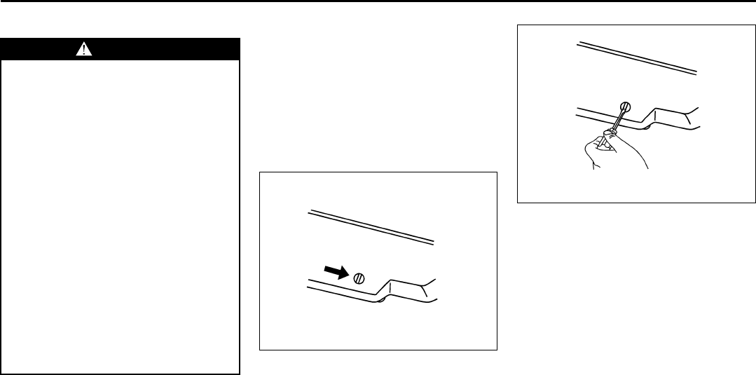
2-7
FEATURES AND CONTROLS
78J00-03E
Liftgate
To unlock the liftgate, press the unlock but-
ton on the Remote Keyless Entry (RKE)
transmitter twice or use the power door
lock switch.
To lock the liftgate, press the lock button
on the RKE transmitter or use the power
door lock switch. The liftgate does not
have a key lock cylinder.
To open the liftgate, pull up on the handle
located in the center of the liftgate.
When closing the liftgate, use the molded
handles to pull the liftgate down. Push the
liftgate closed until it latches.
Liftgate Operation with Loss of Power
The liftgate is equipped with an electric
latch. If the battery is disconnected or has
low voltage, the liftgate will not open.
1799172
To open the liftgate if this happens,
remove the interior trim plug located at the
base of the liftgate from inside the vehicle.
1799191
Use a tool to push the service release
lever located on the latch until you hear or
feel the gate release. The liftgate can now
be opened and closed manually. You will
need to use this procedure to open the lift-
gate until the power is restored.
WARNING
It can be dangerous to drive with the
liftgate or liftglass open because car-
bon monoxide (CO) gas can come
into your vehicle. You cannot see or
smell CO. It can cause unconscious-
ness and even death. If you must
drive with the liftgate open or if elec-
trical wiring or other cable connec-
tions must pass through the seal
between the body and the liftgate or
liftglass:
• Make sure all other windows are
shut.
• Turn the fan on your climate con-
trol system to its highest speed
and select the control setting that
will force outside air into your vehi-
cle. See “Climate Control System”
in the Index.
• If you have air outlets on or under
the instrument panel, open them all
the way. Refer to “Engine Exhaust”
in this section.
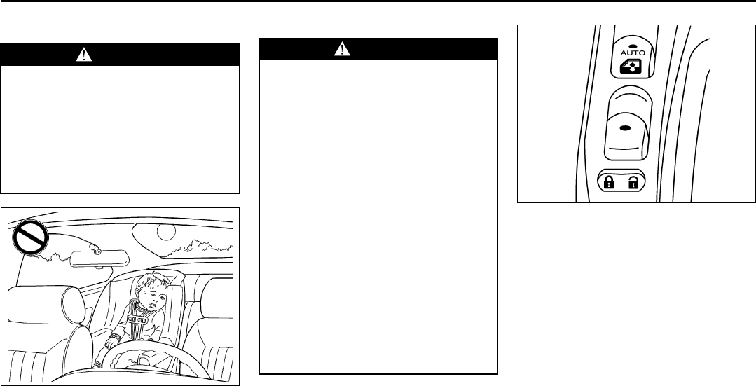
2-8
FEATURES AND CONTROLS
78J00-03E
Windows
811448
Power Windows
1235612
The window switches are located on each
side of the shift lever on the center con-
sole.
To lower a window, press the switch down.
To raise a window, pull the switch up.
The power windows operate when the igni-
tion is in RUN or ACC.
A window switch is also located on each
rear door. Press the bottom of the switch to
lower the window. Press the top of the
switch to raise the window.
Express-Down Window
The driver’s window switch has an
express-down feature that is labeled
AUTO. This allows the driver’s window to
open fully without having to continuously
press the switch. Press the switch to the
second position and the driver’s window
WARNING
Leaving children, helpless adults, or
pets in a vehicle with the windows
closed is dangerous. They can be
overcome by the extreme heat and
suffer permanent injuries or even
death from heat stroke. Never leave a
child, a helpless adult, or a pet alone
in a vehicle, especially with the win-
dows closed in warm or hot weather.
WARNING
Leaving children, helpless adults, or
pets in a vehicle with the windows
closed is dangerous. They can be
overcome from extreme heat in warm
or hot weather and suffer permanent
injuries or even death from heat
stroke.
Leaving children in a vehicle with the
ignition key is dangerous for many
reasons, children or others could be
badly injured or even killed. They
could operate the power windows or
other controls or even make the vehi-
cle move. The windows will function
with the keys in the ignition and they
could be seriously injured or killed if
caught in the path of a closing win-
dow. Do not leave keys in a vehicle
with children.
When there are children in the rear
seat use the window lockout button
to prevent unintentional operation of
the windows.

2-9
FEATURES AND CONTROLS
78J00-03E
will go all the way down. To stop the win-
dow from lowering, lift the switch all the
way up and release it.
Window Lockout
The driver’s window switches also include
a lockout switch. Press the left side of the
switch to prevent rear passengers from
using their window switches. The driver
can still control all the windows with the
lockout on. Press the right side of the win-
dow lockout switch to return to normal win-
dow operation.
Sun Visors
To block out glare, swing the sun visor
down. You can also detach the driver’s sun
visor from the center mount and slide it
along the rod from side-to-side for greater
coverage.
Visor Vanity Mirrors
Your vehicle has covered visor vanity mir-
rors on both the driver’s and passenger’s
side.
Theft-Deterrent Systems
Vehicle theft is big business, especially in
some cities. Although your vehicle has a
number of theft-deterrent features, we
know that nothing we put on it can make it
impossible to steal.
Content Theft-Deterrent
To activate the theft-deterrent system:
1) Open the door.
2) Lock the door with the power door lock
switch or the remote keyless entry
transmitter. If you are using the remote
keyless entry transmitter, the door does
not need to be open.
3) Close all doors.
Once armed, the alarm will go off if some-
one tries to enter the vehicle without using
the remote keyless entry transmitter or a
key or turns the ignition on with an incor-
rect key. The horn will sound and the turn
signal lamps will flash for approximately
two minutes.
When the alarm is armed, the trunk may
be opened with the remote keyless entry
transmitter. The power door lock switches
are disabled and the doors remain locked.
You must use your remote keyless entry
transmitter or your key to unlock the doors
when the system is armed.
Arming with the Power Lock Switch
The alarm system will arm when you use
either power lock switch to lock the doors
while any door or the trunk is open and the
key is removed from the ignition.
Arming with the Remote Keyless Entry
Transmitter
The alarm system will arm when you use
your remote keyless entry transmitter to
lock the doors, if the key is not in the igni-
tion.
Disarming with the Remote Keyless
Entry Transmitter
The alarm system will disarm when you
use your remote keyless entry transmitter
to unlock the doors.
The first time a remote unlock command is
received, three flashes will be seen and
three horn chirps heard to indicate an
alarm condition has occurred since last
arming.
Disarming with Your Key
The alarm system will disarm when you
use your key to unlock the doors or insert
your key in ignition and turn it from the
LOCK position.

2-10
FEATURES AND CONTROLS
78J00-03E
PASS-Key® III+
The PASS-Key® III+ system operates on a
radio frequency subject to Federal Com-
munications Commission (FCC) Rules and
with Industry Canada.
This device complies with Part 15 of the
FCC Rules. Operation is subject to the fol-
lowing two conditions:
1) This device may not cause harmful
interference.
2) This device must accept any interfer-
ence received, including interference
that may cause undesired operation.
This device complies with RSS-210 of
Industry Canada. Operation is subject to
the following two conditions:
1) This device may not cause interfer-
ence.
2) This device must accept any interfer-
ence received, including interference
that may cause undesired operation of
the device.
Changes or modifications to this system by
other than an authorized service facility
could void authorization to use this equip-
ment.
PASS-Key® III+ uses a radio frequency
transponder in the key that matches a
decoder in your vehicle.
PASS-Key® III+ Operation
Your vehicle has PASS-Key® III+ (Person-
alized Automotive Security System) theft-
deterrent system. PASS-Key® III+ is a pas-
sive theft-deterrent system. This means
you do not have to do anything special to
arm or disarm the system. It works when
you transition the key to RUN, ACC or
START from the LOCK position.
When the PASS-Key® III+ system senses
that someone is using the wrong key, it
prevents the vehicle from starting. Anyone
using a trial-and-error method to start the
vehicle will be discouraged because of the
high number of electrical key codes.
If the engine does not start and the secu-
rity light on the instrument panel comes on
when trying to start the vehicle, the key
may have a damaged transponder. Turn
the ignition off and try again.
If the engine still does not start, and the
key appears to be undamaged, try another
ignition key. At this time, you may also
want to check the fuse, refer to “Fuses and
Circuit Breakers” in “Electrical System” in
the “Service and Appearance Care” sec-
tion. If the engine still does not start with
the other key, your vehicle needs service.
If your vehicle does start, the first key may
be faulty. See your dealer who can service
the PASS-Key® III+ to have a new key
made. In an emergency, contact Roadside
Assistance.
It is possible for the PASS-Key® III+
decoder to “learn” the transponder value of
a new or replacement key. Up to nine addi-
tional keys may be programmed for the
vehicle. The following procedure is for pro-
gramming additional keys only. If all the
currently programmed keys are lost or do
not operate, you must see your dealer or a
locksmith who can service PASS-Key® III+
to have keys made and programmed to the
system.
See your dealer or a locksmith who can
service PASS-Key® III+ to get a new key
blank that is cut exactly as the ignition key
that operates the system.
To program the new additional key do the
following:
1) Verify that the new key has a
stamped on it.
2) Insert the original, already pro-
grammed, key in the ignition and start
the engine. If the engine will not start,
see your dealer for service.
3) After the engine has started, turn the
key to LOCK, and remove the key.
4) Insert the new key to be programmed
and turn it to the RUN position within
five seconds of removing the original
key.
5) The security light will turn off once the
key has been programmed.
6) Repeat Steps 1 through 5 if additional
keys are to be programmed.

2-11
FEATURES AND CONTROLS
78J00-03E
If you are driving and the security light
comes on and stays on, you may be able
to restart your engine. Your PASS-Key®
III+ system, however, may not be working
properly and must be serviced by your
dealer.
If you lose or damage your PASS-Key®
III+ key, see your dealer or a locksmith
who can service PASS-Key® III+ to have a
new key made.
Daily Inspection Checklist
Before Driving
1) Make sure that windows, mirrors, lights
and reflectors are clean and unob-
structed.
2) Visually check the tires for the following
points:
– the depth of the tread groove
– abnormal wear, cracks and damage
– loose wheel nuts
– existence of foreign material such as
nails, stones, etc.
Refer to “Tires” in the “SERVICE AND
APPEARANCE CARE” section for details.
3) Look for oil or other fluid leaks.
NOTE:
It is normal for water to drip from the air
conditioning system after use.
4) Make sure the hood is fully closed and
latched.
5) Check the headlights, turn signal lights,
brake lights and horn for proper opera-
tion.
6) Lock all doors.
7) Adjust the seat and adjustable head
restraints (if equipped).
8) Check the brake pedal.
9) Adjust the mirrors.
10)Make sure that you and all passengers
have properly fastened your safety
belts.
11)Make sure that all warning lights come
on as the key is turned to the “ON” or
“START” position.
12)Check all gauges.
13)Make sure that the BRAKE light turns
off when the parking brake is released.
Once a week, or each time you fill your fuel
tank, perform the following under-hood
checks:
1) Engine oil level
2) Coolant level
3) Brake fluid level
4) Power steering (if equipped) fluid level
5) Windshield washer fluid level
6) Hood latch operation
Pull the hood release handle inside the
vehicle. Make sure that you cannot
open the hood all the way without
releasing the secondary latch. Be sure
to close the hood securely after check-
ing for proper latch operation. Refer to
“Lubricate body components” under
“Scheduled Maintenance” in the
“Maintenance Schedule” section for the
lubrication schedule.
WARNING
Make sure the hood is fully closed
and latched before driving. If it is not,
it can fly up unexpectedly during
driving, obstructing your view and
resulting in an accident.
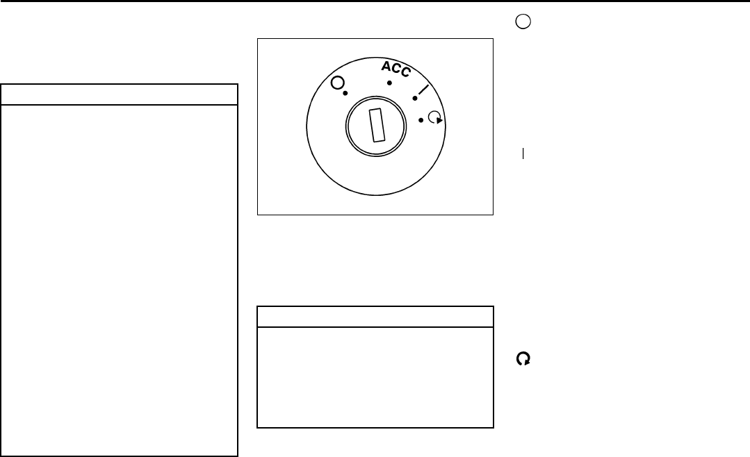
2-12
FEATURES AND CONTROLS
78J00-03E
Starting and Operating Your
Vehicle
New Vehicle Break-In
Ignition Positions
1410037
With the key in the ignition switch, you can
turn it to four different positions. A warning
tone will sound if you open the driver’s
door when the key has not been removed
from the ignition.
(LOCK):
You will only be able to remove your key
when the ignition is turned to LOCK.
The ignition switch cannot be turned to
LOCK unless the shift lever is in PARK (P).
ACC (Accessory):
This position operates some of your elec-
trical accessories.
(RUN):
This is the position the switch returns to
after you start your engine and release the
switch. The switch stays in the RUN posi-
tion when the engine is running. But even
when the engine is not running, you can
use RUN to operate your electrical acces-
sories and to display some warning and
indicator lights.
The battery could be drained if you leave
the key in the ACC or RUN position with
the engine off. You may not be able to start
your vehicle if the battery is allowed to
drain for an extended period of time.
(START):
This position starts the engine. When the
engine starts, release the key. The ignition
switch will return to RUN for normal driv-
ing.
Key In the Ignition
Never leave your vehicle with the keys
inside, as it is an easy target for joy riders
or thieves. If you leave the key in the igni-
CAUTION
Your vehicle does not need an elabo-
rate break-in. But it will perform bet-
ter in the long run if you follow these
guidelines:
• Do not drive at any one constant
speed, fast or slow, for the first 500
miles (805 km). Do not make full-
throttle starts. Avoid downshifting
to brake, or slow, the vehicle.
• Avoid making hard stops for the
first 200 miles (322 km) or so. Dur-
ing this time your new brake linings
are not yet broken in. Hard stops
with new linings can mean prema-
ture wear and earlier replacement.
Follow this breaking-in guideline
every time you get new brake lin-
ings.
• Do not tow a trailer during break-in.
Refer to “Towing a Trailer” in “Tow-
ing” in the “Driving Your Vehicle”
section for the trailer towing capa-
bilities of your vehicle and more
information.
Following break-in, engine speed and
load can be gradually increased.
CAUTION
Using a tool to force the key from the
ignition switch could cause damage
or break the key. Use the correct key
and turn the key only with your hand.
Make sure the key is in all the way. If
none of this works, then your vehicle
needs service.

2-13
FEATURES AND CONTROLS
78J00-03E
tion and park your vehicle, a chime will
sound, when you open the driver’s door.
Always remember to remove your key from
the ignition and take it with you. This will
lock your ignition and transaxle. Also,
always remember to lock the doors.
The battery could be drained if you leave
the key in the ignition while your vehicle is
parked. You may not be able to start your
vehicle after it has been parked for an
extended period of time.
Retained Accessory Power (RAP)
The vehicle has Retained Accessory
Power (RAP), which will allow your vehi-
cle’s radio and windows to work when the
ignition key is in RUN or ACC. Once the
key is turned from RUN to LOCK the radio
will continue to work 10 minutes or until the
driver’s door is opened. Also, the power
windows will continue to work for up to 10
minutes or until any door is opened.
Starting the Engine
Place the transaxle in the proper gear.
Move your shift lever to PARK (P) or NEU-
TRAL (N). Your engine will not start in any
other position -- this is a safety feature. To
restart when you are already moving, use
NEUTRAL (N) only.
Starting Procedure
1) With your foot off the accelerator pedal,
turn the ignition key to START. When
the engine starts, let go of the key. The
idle speed will go down as your engine
gets warm. Do not race the engine
immediately after starting it. Operate
the engine and transaxle gently to allow
the oil to warm up and lubricate all mov-
ing parts.
Your vehicle has a Computer-Con-
trolled Cranking System. This feature
assists in starting the engine and pro-
tects components. If the ignition key is
turned to the START position, and then
released when the engine begins
cranking, the engine will continue
cranking for a few seconds or until the
vehicle starts. If the engine does not
start and the key is held in START for
many seconds, cranking will be stopped
after 15 seconds to prevent cranking
motor damage. To prevent gear dam-
age, this system also prevents cranking
if the engine is already running. Engine
cranking can be stopped by turning the
ignition switch to the ACC or LOCK
position.
2) If the engine does not start after 5-10
seconds, especially in very cold
weather (below 0°F –18°C), it could be
flooded with too much gasoline. Try
pushing the accelerator pedal all the
way to the floor and holding it there as
you hold the key in START for up to a
maximum of 15 seconds. Wait at least
15 seconds between each try, to allow
the cranking motor to cool down. When
the engine starts, let go of the key and
accelerator. If the vehicle starts briefly
but then stops again, do the same
thing. This clears the extra gasoline
from the engine. Do not race the engine
immediately after starting it. Operate
the engine and transaxle gently until
CAUTION
Shifting into PARK (P) with the vehi-
cle moving could damage the tran-
saxle. Shift into PARK (P) only when
your vehicle is stopped.
CAUTION
Cranking the engine for long periods
of time, by returning the key to the
START position immediately after
cranking has ended, can overheat
and damage the cranking motor, and
drain the battery. Wait at least 15 sec-
onds between each try, to allow the
cranking motor to cool down.
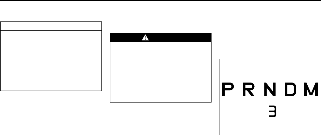
2-14
FEATURES AND CONTROLS
78J00-03E
the oil warms up and lubricates all mov-
ing parts.
Engine Coolant Heater
If your vehicle has this feature, in very cold
weather 0°F (–18°C) or colder, the engine
coolant heater can help. You will get easier
starting and better fuel economy during
engine warm-up. Usually, the coolant
heater should be plugged in a minimum of
four hours prior to starting your vehicle. At
temperatures above 32°F (0°C), use of the
coolant heater is not required. Your vehicle
may also have an internal thermostat in
the plug end of the cord. This will prevent
operation of the engine coolant heater
when the temperature is at or above 0°F (–
18°C) as noted on the cord.
To Use the Engine Coolant Heater
1) Turn off the engine.
2) Open the hood and unwrap the electri-
cal cord. The cord is located on the
passenger’s side of the engine com-
partment, near the radiator.
3) Plug it into a normal, grounded 110-volt
AC outlet.
4) Before starting the engine, be sure to
unplug and store the cord as it was
before to keep it away from moving
engine parts. If you do not, it could be
damaged.
How long should you keep the coolant
heater plugged in? The answer depends
on the outside temperature, the kind of oil
you have, and some other things. Instead
of trying to list everything here, we ask that
you contact your dealer in the area where
you will be parking your vehicle. The
dealer can give you the best advice for that
particular area.
Automatic Transaxle Operation
The shift lever for the automatic transaxle
is located on the console between the
seats.
Maximum engine speed is limited when
the vehicle is in PARK (P) or NEUTRAL
(N) to protect driveline components from
improper operation.
1722684
There are several different positions for the
shift lever. When using the manual shift
mode a number will also appear on the tell-
tale line below the gear selections. For
more information on the manual shift
option see “Manual Shift Mode” in this sec-
tion.
PARK (P):
This position locks the front wheels. It is
the best position to use when the engine is
CAUTION
Your engine is designed to work with
the electronics in your vehicle. If you
add electrical parts or accessories,
you could change the way the engine
operates. Before adding electrical
equipment, check with your dealer. If
you do not, your engine might not
perform properly. Any resulting dam-
age would not be covered by your
vehicle’s warranty.
WARNING
Plugging the cord into an
ungrounded outlet could cause an
electrical shock. Also, the wrong kind
of extension cord could overheat and
cause a fire. You could be seriously
injured. Plug the cord into a properly
grounded three-prong 110-volt AC
outlet. If the cord will not reach, use a
heavy-duty three-prong extension
cord rated for at least 15 amps.
2-15
FEATURES AND CONTROLS
78J00-03E
started because the vehicle cannot move
easily.
Make sure the shift lever is fully in PARK
(P) before starting the engine. The vehicle
has an automatic transaxle shift lock con-
trol system. You must fully apply your reg-
ular brakes first and then press the shift
lever button, before you can shift from
PARK (P) when the ignition is in RUN. If
you cannot shift out of PARK (P), ease
pressure on the shift lever and push the
shift lever all way into PARK (P) as you
maintain brake application. Then press the
shift lever button and move the shift lever
into another gear. Refer to “Shifting Out of
Park (P)” in this section.
REVERSE (R):
Use this gear to back up.
To rock the vehicle back and forth to get
out of snow, ice, or sand without damaging
the transaxle, refer to “If Your Vehicle is
Stuck in Sand, Mud, Ice, or Snow” in “Your
Driving, the Road, and Your Vehicle” in the
“Driving Your Vehicle” section.
NEUTRAL (N):
In this position, the engine does not con-
nect with the wheels. To restart when the
vehicle is already moving, use NEUTRAL
(N) only. Also, use NEUTRAL (N) when the
vehicle is being towed.
DRIVE (D):
This position is for normal driving. It pro-
vides the best fuel economy for your vehi-
cle. If the vehicle needs more power for
passing, and it is:
• Going less than 35 mph (55 km/h), push
the accelerator pedal about halfway
down.
• Going about 35 mph (55 km/h) or more,
push the accelerator pedal all the way
down. The vehicle will shift down to the
next gear and have more power.
WARNING
It is dangerous to get out of your
vehicle if the shift lever is not fully in
PARK (P) with the parking brake
firmly set. Your vehicle can roll.
Do not leave your vehicle when the
engine is running unless you have to.
If you have left the engine running,
the vehicle can move suddenly. You
or others could be injured. To be sure
your vehicle will not move, even
when you are on fairly level ground,
always set your parking brake and
move the shift lever to PARK (P).
Refer to “Shifting Into Park (P)” in
this section. If you are pulling a
trailer, refer to “Towing a Trailer” in
“Towing” in the “Driving Your Vehi-
cle” section.
CAUTION
Shifting to REVERSE (R) while your
vehicle is moving forward could dam-
age the transaxle. The repairs would
not be covered by your warranty.
Shift to REVERSE (R) only after your
vehicle is stopped.
WARNING
Shifting into a drive gear while your
engine is running at high speed is
dangerous. Unless your foot is firmly
on the brake pedal, your vehicle
could move very rapidly. You could
lose control and hit people or
objects. Do not shift into a drive gear
while your engine is running at high
speed.
CAUTION
Shifting out of PARK (P) or NEUTRAL
(N) while the engine is running at
high speed may damage the tran-
saxle. The repairs would not be cov-
ered by your warranty. Be sure the
engine is not running at high speeds
when shifting your vehicle.

2-16
FEATURES AND CONTROLS
78J00-03E
Downshifting the transaxle in slippery road
conditions could result in skidding, refer to
“Loss of Control” in “Your Driving, the
Road, and Your Vehicle” in the “Driving
Your Vehicle” section.
MANUAL SHIFT MODE (M):
This position, available on the models with
the Manual Shift Mode (MSM), allows you
to change gears similar to a manual tran-
saxle. If your vehicle has this feature, see
“Manual Shift Mode (MSM)”.
Manual Shift Mode (MSM)
(Automatic Transaxle)
1722685
To use this feature, do the following:
1) Move the shift lever from DRIVE (D) to
the left into the MANUAL SHIFT MODE
(M).
While driving in manual mode, the tran-
saxle will remain in the driver selected
gear.
When coming to a stop in the manual
position, the vehicle will automatically
shift into FIRST (1) gear.
– A shift is required to protect the engine
or transmission or
– The vehicle slows almost to a stop,
and then automatic downshift will
occur.
2) Press the shift lever forward to upshift
or rearward to downshift.
A box with the current gear will display in
the middle of the telltale line below the
gear selection.
While using the Manual Shift Mode (MSM)
feature the vehicle will have firmer shifting
and increased performance. You can use
this for sport driving or when climbing hills
to stay in gear longer or to downshift for
more power or engine braking.
The transaxle will only allow you to shift
into gears appropriate for the vehicle
speed and engine revolutions per minute
(RPM):
• The transaxle will not downshift to the
next lower gear if the engine RPM is too
high.
• The transaxle will not automatically shift
to the next higher gear if the engine
RPM is too high.
• When coming to a stop in the manual
mode, the vehicle will automatically
downshift to the proper gear based on
speed. Upon acceleration you will need
to manually upshift to the desired gear.
CAUTION
Spinning the tires or holding the
vehicle in one place on a hill using
only the accelerator pedal may dam-
age the transaxle. If you are stuck, do
not spin the tires. When stopping on
a hill, use the brakes to hold the vehi-
cle in place.
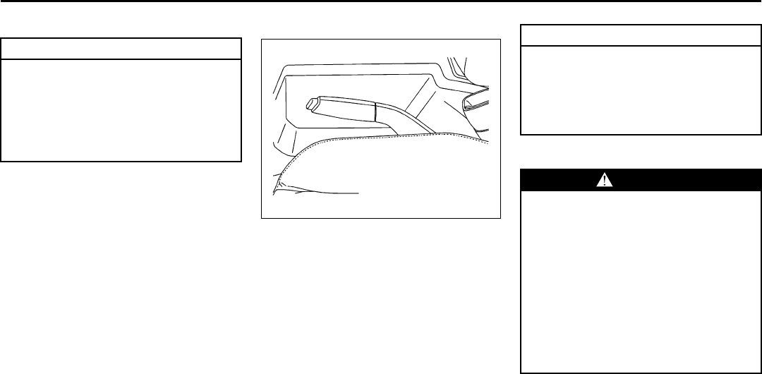
2-17
FEATURES AND CONTROLS
78J00-03E
SECOND (2) Gear Start Feature
When accelerating your vehicle from a
stop in snowy and icy conditions, you may
want to shift into SECOND (2). A higher
gear, and light application of the gas pedal,
may allow you to gain more traction on
slippery surfaces.
With the MANUAL SHIFT MODE, the vehi-
cle can accelerate from a stop in SECOND
(2).
1) Move the shift lever from DRIVE (D)
into the MANUAL SHIFT MODE (M)
position.
2) With the vehicle stopped, press the
plus (+) paddle forward to select SEC-
OND (2). The vehicle will start from a
stop position in SECOND (2).
3) Once the vehicle is moving select the
desired drive gear.
Parking Brake
1722713
The parking brake lever is located to the
right of the driver’s seat.
To set the parking brake, hold the brake
pedal down and pull up on the parking
brake lever. If the ignition is on, the brake
system warning light will come on.
To release the parking brake, hold the
brake pedal down. Pull the parking brake
lever up until you can press the release
button. Hold the release button in as you
move the brake lever all the way down.
Make sure to release the parking brake
before driving the vehicle.
If the parking brake is applied and the vehi-
cle is moving at least 4 mph (6 km/h), a
chime will activate to remind you to release
the parking brake.
Shifting Into Park (P)
1) Hold the brake pedal down and set the
parking brake.
2) Move the shift lever into the PARK (P)
position by holding in the button on the
shift lever and pushing it all the way
toward the front of the vehicle.
3) Turn the ignition key to LOCK.
CAUTION
If you attempt a third gear start while
trailering or towing a heavy load, you
will notice reduced engine power.
This could overheat and damage
your transaxle. Do not attempt a third
gear start while trailering or towing
your vehicle.
CAUTION
Driving with the parking brake on can
overheat the brake system and cause
premature wear or damage to brake
system parts. Verify that the parking
brake is fully released and the brake
warning light is off before driving.
WARNING
It can be dangerous to get out of your
vehicle if the shift lever is not fully in
PARK (P) with the parking brake
firmly set. Your vehicle can roll. If
you have left the engine running, the
vehicle can move suddenly. You or
others could be injured. To be sure
your vehicle will not move, even
when you are on fairly level ground,
use the steps that follow. If you are
pulling a trailer, refer to “Towing a
Trailer” in “Towing” in the “Driving
Your Vehicle” section.
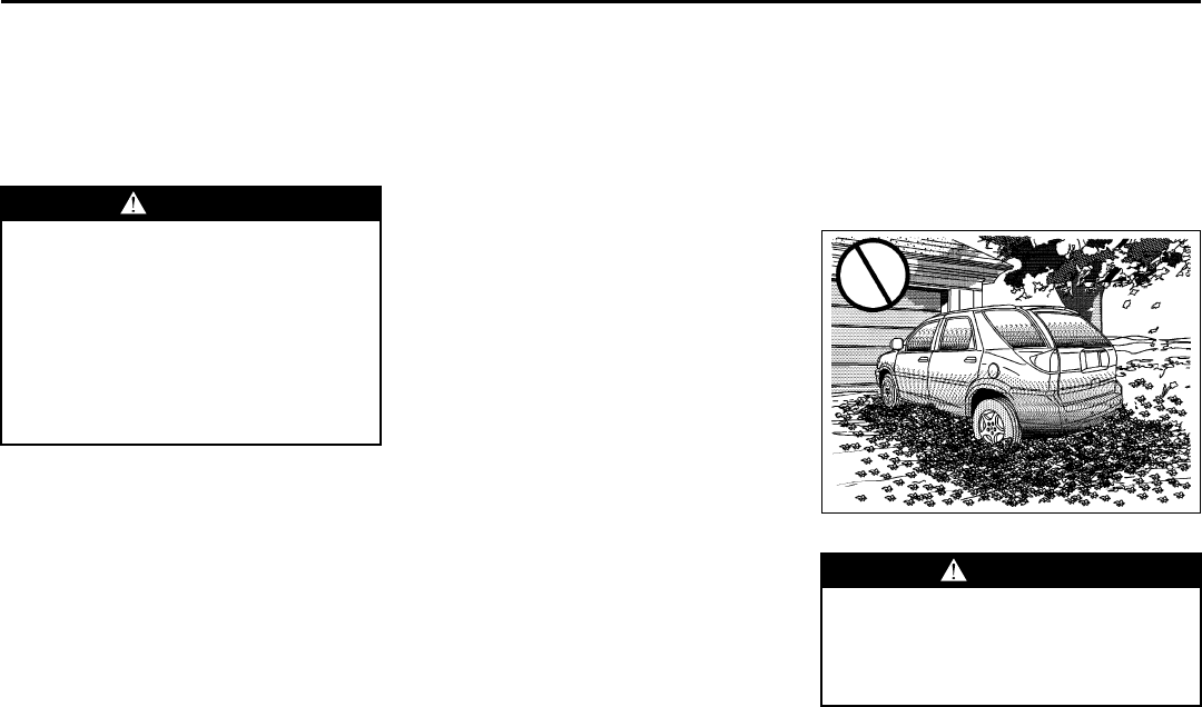
2-18
FEATURES AND CONTROLS
78J00-03E
4) Remove the key and take it with you. If
you can leave your vehicle with the igni-
tion key in your hand, your vehicle is in
PARK (P).
Leaving Your Vehicle With the Engine
Running
If you have to leave your vehicle with the
engine running, be sure your vehicle is in
PARK (P) and your parking brake is firmly
set before you leave it. After you have
moved the shift lever into PARK (P), hold
the regular brake pedal down. Then, see if
you can move the shift lever away from
PARK (P) without first pushing the button.
If you can, it means that the shift lever was
not fully locked into PARK (P).
Torque Lock
If you are parking on a hill and you do not
shift your transaxle into PARK (P) properly,
the weight of the vehicle may put too much
force on the parking pawl in the transaxle.
You may find it difficult to pull the shift
lever out of PARK (P). This is called
“torque lock.” To prevent torque lock, set
the parking brake and then shift into PARK
(P) properly before you leave the driver’s
seat. To find out how, refer to “Shifting Into
Park (P)” in this section.
When you are ready to drive, move the
shift lever out of PARK (P) before you
release the parking brake.
If torque lock does occur, you may need to
have another vehicle push yours a little
uphill to take some of the pressure from
the parking pawl in the transaxle, so you
can pull the shift lever out of PARK (P).
Shifting Out of Park (P)
Your vehicle has an automatic transaxle
shift lock control system. You have to fully
apply your regular brakes before you can
shift from PARK (P) when the ignition is in
RUN.
If you cannot shift out of PARK (P), ease
pressure on the shift lever – push the shift
lever all the way into PARK (P), as you
maintain brake application. Then, press
the button on the shift lever and move the
shift lever into the gear you wish.
If you ever hold the brake pedal down but
still cannot shift out of PARK (P), try this:
1) Turn the key to LOCK.
2) Apply and hold the brake until the end
of Step 4.
3) Shift to NEUTRAL (N).
4) Start the vehicle and then shift to the
desired drive gear.
5) Have your vehicle fixed as soon as you
can.
Parking Over Things That Burn
806406
WARNING
It can be dangerous to leave your
vehicle with the engine running. Your
vehicle could move suddenly if the
shift lever is not fully in PARK (P)
with the parking brake firmly set.
And, if you leave the vehicle with the
engine running, it could overheat and
even catch fire. You or others could
be injured. Do not leave your vehicle
with the engine running.
WARNING
Things that can burn could touch hot
exhaust parts under your vehicle and
ignite. Do not park over papers,
leaves, dry grass, or other things that
can burn.
2-19
FEATURES AND CONTROLS
78J00-03E
Engine Exhaust Running the Engine While Parked
It is better not to park with the engine run-
ning. But if you ever have to, here are
some things to know.
Follow the proper steps to be sure your
vehicle will not move. Refer to “Shifting
Into Park (P)” in this section.
If you are parking on a hill and if you are
pulling a trailer, also refer to “Towing a
Trailer” in “Towing” in the “Driving Your
Vehicle” section.
WARNING
Engine exhaust can kill. It contains
the gas carbon monoxide (CO), which
you cannot see or smell. It can cause
unconsciousness and death.
You might have exhaust coming in if:
• The exhaust system sounds
strange or different.
• Your vehicle gets rusty under-
neath.
• Your vehicle was damaged in a col-
lision.
• Your vehicle was damaged when
driving over high points on the
road or over road debris.
• Repairs were not done correctly.
• Your vehicle or the exhaust system
has been modified improperly.
If you ever suspect exhaust is com-
ing into your vehicle:
• Drive it only with all the windows
down to blow out any CO; and
• Have your vehicle fixed immedi-
ately.
WARNING
Idling the engine with the climate
control system off could allow dan-
gerous exhaust into your vehicle.
Refer to the earlier caution under
“Engine Exhaust” in this section.
Also, idling in a closed-in place can
let deadly carbon monoxide (CO) into
your vehicle even if the climate con-
trol fan is at the highest setting. One
place this can happen is a garage.
Exhaust – with CO – can come in eas-
ily. NEVER park in a garage with the
engine running.
Another closed-in place can be a bliz-
zard. Refer to “Winter Driving” in
“Your Driving, the Road, and Your
Vehicle” in the “Driving Your Vehi-
cle” section.
WARNING
It can be dangerous to get out of your
vehicle if the shift lever is not fully in
PARK (P) with the parking brake
firmly set. Your vehicle can roll. Do
not leave your vehicle when the
engine is running unless you have to.
If you have left the engine running,
the vehicle can move suddenly. You
or others could be injured. To be sure
your vehicle will not move, even
when you are on fairly level ground,
always set your parking brake and
move the shift lever to PARK (P).
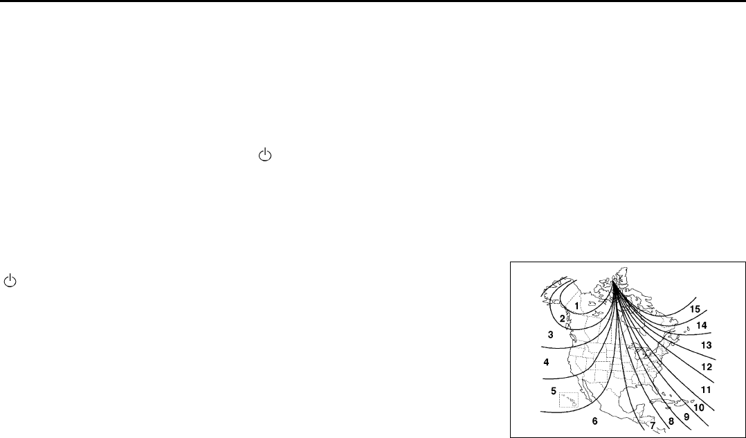
2-20
FEATURES AND CONTROLS
78J00-03E
Mirrors
Manual Rearview Mirror
To adjust the angle of the mirror, move the
mirror to a position that allows you see to
out of the back window. To adjust the
height of the mirror, adjust the arm that
connects the mirror to the windshield.
To reduce glare from lights behind you,
move the lever toward you to the night
position.
Automatic Dimming Rearview
Mirror
If the vehicle has this feature, the auto-
matic dimming mirror automatically dims to
the proper level to minimize glare at night
from lights behind your vehicle.
On/Off:
This is the on/off button. A light near the
on/off button will come on to indicate the
automatic dimming is on.
If the automatic dimming function is off,
press and hold the on/off button for four
seconds to manually turn the system back
on.
Cleaning the Mirror
When cleaning the mirror, use a paper
towel or similar material dampened with
glass cleaner. Do not spray glass cleaner
directly on the mirror as that may cause
the liquid cleaner to enter the mirror hous-
ing.
Automatic Dimming Rearview
Mirror with Compass
Your vehicle may have an automatic-dim-
ming rearview mirror with a compass.
Mirror Operation
When turned on, this mirror automatically
dims to the proper level to minimize glare
from any headlamps behind you after dark.
On/Off:
This is the on/off button for the automatic
dimming feature and compass. Press the
far left button, located below the mirror
face, for up to four seconds to turn the fea-
ture on and off. A light on the mirror will be
lit while the feature is turned on.
Compass Operation
Press the on/off button once to turn the
compass on or off.
There is a compass display in the window
in the upper right corner of the mirror face.
The compass displays a maximum of two
characters. For example, “NE” is displayed
for north-east.
Compass Calibration
Press and hold the on/off button down for
nine seconds to activate the compass cali-
bration mode. CAL will be displayed in the
compass window on the mirror.
The compass can be calibrated by driving
the vehicle in circles at 5 mph (8 km/h) or
less until the display reads a direction.
Compass Variance
Compass variance is the difference
between earth’s magnetic north and true
geographic north. The mirror is set to zone
eight upon leaving the factory. It will be
necessary to adjust the compass to com-
pensate for compass variance if you live
outside zone eight. Under certain circum-
stances, such as during a long distance
cross-country trip, it will be necessary to
adjust for compass variance. If not
adjusted to account for compass variance,
your compass could give false readings.
To adjust for compass variance, do the fol-
lowing:
1) Find your current location and variance
zone number on the map.
806305
2) Press and hold the on/off button for six
seconds. Release the button when
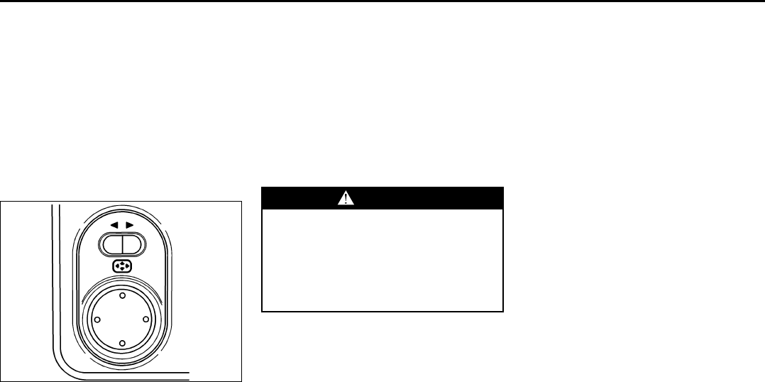
2-21
FEATURES AND CONTROLS
78J00-03E
ZONE is displayed. The number shown
is the current zone number.
3) Scroll through the zone numbers that
appear in the compass/temperature
window on the mirror by pressing the
on/off button. Once you find your zone
number, release the button.
After about four seconds, the mirror will
return to the compass display, and the new
zone number will be set.
Outside Power Mirrors
1262035
The controls for the power mirrors are
located on the instrument panel.
To adjust the mirrors, do the following:
1) Move the selector switch to the left or
right to choose the driver’s or passen-
ger’s mirror.
2) Press the corresponding edges of the
round control pad to move each mirror
to the desired direction.
Adjust each outside mirror so that you can
see a little of your vehicle, and the area
behind your vehicle.
Outside Convex Mirrors
The passenger’s side mirror is convex. A
convex mirror’s surface is curved, creating
a wider area of vision for the driver.
Storage Areas
Glove Box
To open the glove box, lift the handle up.
Cupholder(s)
There are two cupholders, with removable
liners, located in front of the center console
armrest. To access, slide the cover back.
The two cupholders are located in a
removable tray. To remove the tray, press
the tab located at the front of the tray and
pull up. To replace the tray, place the two
tabs at the rear of the tray into the slots
and press the tray down. Underneath the
tray is an additional storage area.
There are cupholders located in the sec-
ond row seat armrest. To access, pull the
armrest down.
If your vehicle has the third row seat, there
will be a cupholder located next to each
side.
Sunglasses Storage Compartment
Your vehicle may have a sunglasses stor-
age compartment located near the rear-
view mirror. Push the cover to open.
Garage Door Opener Compartment
Your vehicle may have a garage door
opener compartment. It is located next to
the sunglasses storage compartment.
Push the latch to open.
WARNING
A convex mirror can make things
(like other vehicles) look farther away
than they really are. If you cut too
sharply into the right lane, you could
hit a vehicle on your right. Check
your inside mirror or glance over
your shoulder before changing lanes.
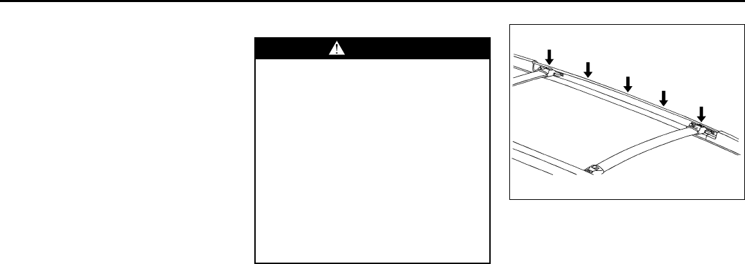
2-22
FEATURES AND CONTROLS
78J00-03E
Center Console Storage Area
Your vehicle has a center console armrest
with storage area. Use the top lever on the
front of the console to open it. There is an
additional storage area underneath the
center console. To access, use the bottom
lever and pull the console up.
Assist Handles
There are assist handles with garment
hooks located above the rear passenger
doors.
Luggage Carrier
A luggage carrier allows you to load things
on top of your vehicle. The luggage carrier
has side rails attached to the roof, sliding
crossrails (if equipped) and places to use
for tying things down. These let you load
some things on top of your vehicle, as long
as they are not wider or longer than the
luggage carrier.
The roof rack crossrails lock in five posi-
tions along the straight section of the side
rail.
1768137
Press the levers down until the locking
mechanisms fully engage to the side rail.
Make sure each lever is in the down posi-
tion. The crossrail will not slide when prop-
erly engaged.
WARNING
If you try to carry something on top
of your vehicle that is longer or wider
than the luggage carrier – like panel-
ing, plywood, a mattress and so forth
– the wind can catch it as you drive
along. This can cause you to lose
control. What you are carrying could
be violently torn off, and this could
cause you or other drivers to have a
collision, and of course damage your
vehicle. You may be able to carry
something like this inside. But, never
carry something longer or wider than
the luggage carrier on top of your
vehicle.
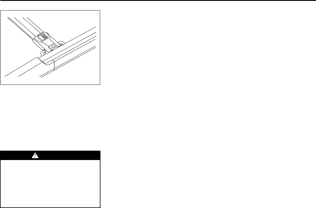
2-23
FEATURES AND CONTROLS
78J00-03E
1767348
To reposition the crossrail, pull up on the
end levers on each side of the crossrail to
the upright position. This will release the
locking mechanism from the siderail. Lift
and place the crossrail into the new posi-
tion. Press the levers down until the lock-
ing mechanisms fully engage to the side
rail. Make sure each lever is in the down
position. The crossrail will not slide when
properly engaged.
Do not stand on the plastic lower body
panel when loading cargo on the luggage
carrier.
Loading cargo on the luggage carrier will
make the center of vehicle gravity higher.
Avoid high speeds, sudden starts, sharp
turns, sudden braking or abrupt maneu-
vers. This could result in loss of control of
the vehicle.
Do not exceed the maximum vehicle
capacity when loading your vehicle. For
more information on vehicle capacity and
loading, refer to “Loading Your Vehicle” in
“Your Driving, the Road, and Your Vehicle”
in the “Driving Your Vehicle” section.
To prevent damage or loss of cargo as you
are driving, check now and then to make
sure the luggage carrier crossrails are
locked and cargo is still securely fastened.
When the luggage carrier is not in use,
store the crossrails inside the vehicle. If
not possible, lock one crossrail at the rear
most position on the siderails and lock the
other crossrail above the opening of the
rear door to reduce wind noise.
Rear Seat Armrest
Your vehicle may have a rear seat armrest
that contains two cupholders. To access
the cupholders, pull the armrest down from
the rear seatback.
Convenience Net
Your vehicle may have a rear compartment
net to prevent items from rolling under the
rear seat. There may also be four conve-
nience net tie-downs. Two tie-downs are
located on the side trim just behind the
rear seat and the other two are located on
the floor at the rear of the cargo area.
WARNING
Loading cargo on the luggage carrier
that weighs more than 220 lbs (100
kg) or hangs over the rear or sides of
the vehicle may damage your vehicle.
Load cargo so that it rests on the
slats as far forward as possible and
against the side rails, making sure to
fasten it securely.
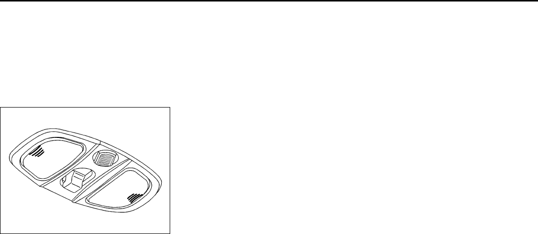
2-24
FEATURES AND CONTROLS
78J00-03E
Sunroof
If your vehicle has this feature, the sunroof
switch is located on the headliner above
the rearview mirror. The ignition must be in
RUN or ACC, or Retained Accessory
Power (RAP) must be active, to operate
the sunroof. Refer to “Retained Accessory
Power (RAP)” in this section for more infor-
mation.
1753772
To express-open the sunroof glass panel
and sunshade, press the switch rearward
and release it.
To stop the sunroof before it is completely
open, press the switch rearward again.
The sunshade cannot be closed with the
sunroof open.
To close the sunroof, press forward and
hold the switch until the sunroof stops, lifts,
and seals at the back of the sunroof glass.
Press forward on the switch again to make
sure the sunroof is fully closed.
To put the sunroof in the vent position, pull
down on the front of the switch. Push up on
the front of the switch to close it.

2-25
FEATURES AND CONTROLS
78J00-03E
MEMO

INSTRUMENT PANEL
3
78J00-03E
INSTRUMENT PANEL
Instrument Panel Overview ................................................ 3-1
Climate Controls ................................................................. 3-10
Warning Lights, Gages, and Indicators ............................ 3-15
Driver Information Center (DIC) ......................................... 3-27
Audio System(s) .................................................................. 3-39
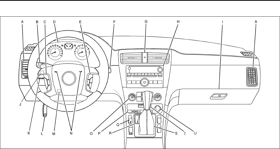
3-1
INSTRUMENT PANEL
78J00-03E
Instrument Panel Overview
1732990

3-2
INSTRUMENT PANEL
78J00-03E
The main components of your instrument
panel are the following:
A. Air Outlets. Refer to “Outlet Adjust-
ment” in this section.
B. Turn Signal/Multifunction Lever. Refer
to “Turn Signal/Multifunction Lever” in
this section.
C. Cruise Controls. Refer to “Cruise
Control” in this section.
D. Instrument Panel Cluster. Refer to
“Instrument Panel Cluster” in this sec-
tion.
E. Audio Steering Wheel Controls. Refer
to “Audio Steering Wheel Controls” in
this section.
F. Windshield Wiper/Washer Lever.
Refer to “Windshield Wipers” in this
section.
G. Hazard Warning Flasher Button.
Refer to “Hazard Warning Flashers” in
this section.
H. Audio System. Refer to “Audio Sys-
tem(s)” in this section.
I. Glove Box. Refer to “Glove Box” in
“Storage Areas” in the “Features and
Controls” section.
J. Power Mirror Control. Refer to “Out-
side Power Mirrors” in “Mirrors” in the
“Features and Controls” section.
K. Instrument Panel Brightness Control.
Refer to “Instrument Panel Bright-
ness” in this section.
L. Hood Release. Refer to “Hood
Release” in “Checking Things Under
the Hood” in the “Service and Appear-
ance Care” section.
M. Tilt Wheel Lever. Refer to “Tilt Wheel”
in this section.
N. Horn. Refer to “Horn” in this section.
O. Climate Controls (If Equipped). Refer
to “Climate Control System” in this
section or Automatic Climate Controls
(If Equipped). Refer to “Automatic Cli-
mate Control System” in this section.
Heated Seats Buttons (If Equipped).
Refer to “Heated Seats” in “Front
Seats” in the “Seats and Restraint
Systems” section.
P. Driver Information Center Controls.
Refer to “DIC Operation and Displays”
in this section. Rear Window Wiper/
Washer Buttons. Refer to “Rear Win-
dow Wiper/Washer” in this section.
Fog Lamps Button. Refer to “Fog
Lamps” in this section.
Q. Power Window Switches. Refer to
“Power Windows” in “Windows” in the
“Features and Controls” section.
R. Traction Control System Button. Refer
to “Traction Control System (TCS)” in
“Your Driving, the Road, and Your
Vehicle” in the “Driving Your Vehicle”
section.
S. Shift Lever. Refer to “Shifting Into
Park (P)” in “Starting and Operating
Your Vehicle” in the “Features and
Controls” section.
T. Passenger Airbag Status Indicator.
Refer to “Passenger Airbag Status
Indicator” in this section.
U. Accessory Power Outlet. Refer to
“Accessory Power Outlet(s)” in this
section.
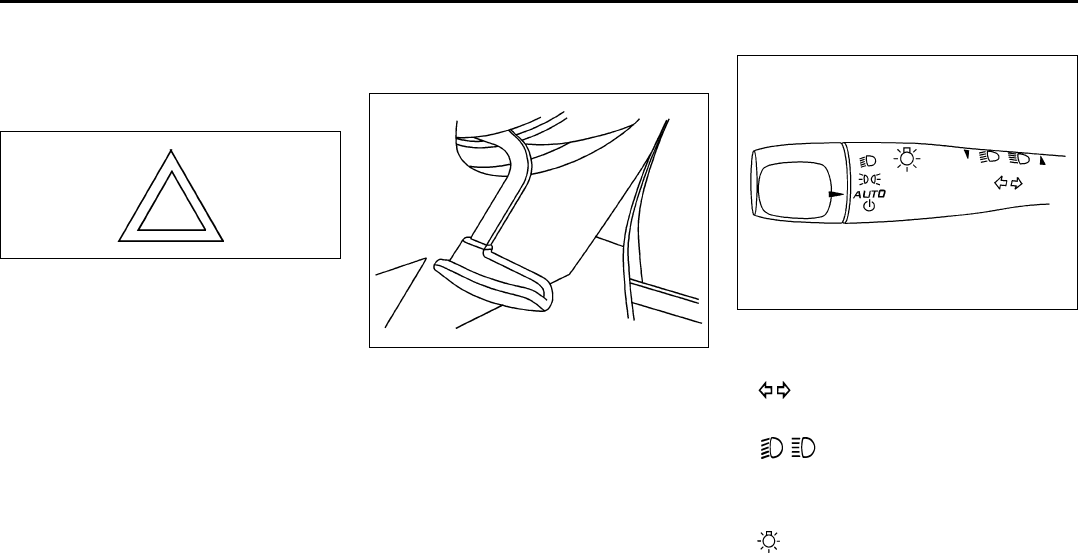
3-3
INSTRUMENT PANEL
78J00-03E
Hazard Warning Flashers
The hazard warning flashers let you warn
the police and others that you have a prob-
lem. The front and rear turn signal lamps
will flash on and off.
1223926
The hazard warning flasher button is
located in the center of the instrument
panel.
The hazard warning flashers work no mat-
ter what position the key is in, and even if
the key is not in the ignition switch.
Press the button to make the front and rear
turn signal lamps flash on and off. Press
the button again to turn the flashers off.
While the hazard warning flashers are on,
the turn signals do not work.
Other Warning Devices
If you carry reflective triangles, you can set
them up at the side of the road about 300
feet (100 m) behind your vehicle.
Horn
Press near or on the horn symbols on your
steering wheel pad to sound the horn.
Tilt Wheel
Your vehicle has a tilt wheel that allows you
to adjust the steering wheel.
1262086
The lever to tilt the steering wheel is
located on the left side of the steering col-
umn.
To tilt the wheel, hold the steering wheel
and push the lever down. Then, move the
steering wheel to a comfortable position
and pull the lever up firmly to lock the col-
umn in place.
Turn Signal/Multifunction Lever
1766015
The lever on the left side of the steering
column includes the following:
• Turn and Lane-Change Signals.
Refer to “Turn and Lane-Change Sig-
nals” in this section.
• Headlamp High/Low-Beam
Changer. Refer to “Headlamp High/Low-
Beam Changer” in this section.
• Flash-to-Pass. Refer to “Flash-to-Pass”
in this section.
• Exterior Lamp Control. Refer to
“Headlamps” in this section.
Turn and Lane-Change Signals
The turn signal has two upward (for right)
and two downward (for left) positions.
These positions allow you to signal a turn
or a lane change.
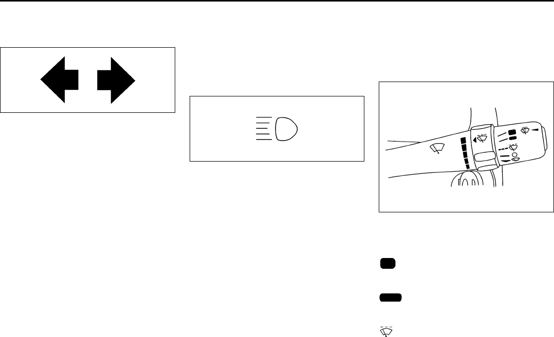
3-4
INSTRUMENT PANEL
78J00-03E
To signal a turn, move the lever all the way
up or down. When the turn is finished, the
lever will return automatically.
808320
An arrow on the instrument panel cluster
will flash in the direction of the turn or lane
change.
To signal a lane change, raise or lower the
lever until the arrow starts to flash. Hold it
there until you complete the lane change.
The lever will return by itself when you
release it.
As you signal a turn or a lane change, if
the arrows flash rapidly, a signal bulb may
be burned out and other drivers won’t see
your turn signal.
If a bulb is burned out, replace it to help
avoid an accident. If the arrows do not go
on at all when you signal a turn, check the
fuse, refer to “Fuses and Circuit Breakers”
in “Electrical System” in the “Service and
Appearance Care” section and for burned-
out bulbs.
Headlamp High/Low-Beam Changer
To change the headlamps from low beam
to high, push the turn signal lever away
from you. To change from high beam to low
beam, pull the turn signal lever towards
you. To flash the high beams from low
beam, pull the turn signal lever all the way
towards you. Then release it.
1799557
When the high beams are on, this light on
the instrument panel cluster will also be
on.
Flash-to-Pass
This feature lets you use your high-beam
headlamps to signal a driver in front of you
that you want to pass.
To flash the high beams from low beam,
pull the turn signal/multifunction lever all
the way towards you. Then release it.
Windshield Wipers
Be sure to clear ice and snow from the
wiper blades before using them. If the
wiper blades are frozen to the windshield,
gently loosen or thaw them. If the blades
do become damaged, install new blades or
blade inserts. Refer to “Windshield Wiper
Blade Replacement” in the “Service and
Appearance Care” section.
Heavy snow or ice can overload the wiper
motor. A circuit breaker will stop the motor
until it cools down. Clear away snow or ice
to prevent an overload.
1766016
Use the lever on the right side of the steer-
ing column to operate the windshield wip-
ers.
(High Speed):
Move the lever to this position for steady
wiping at high speed.
(Low Speed):
Move the lever to this position for steady
wiping at low speed.
(Delay):
Move the lever to this position to set a
delay between wipes.
3-5
INSTRUMENT PANEL
78J00-03E
(Delay Adjustment):
Move the lever to the delay position to
choose a delayed wiping cycle. Turn the
intermittent adjust band down for a longer
delay or up for a shorter delay.
(Off):
Move the lever to this position to turn off
the windshield wipers.
(Mist):
Move the lever all the way down to mist
and release for a single wiping cycle. The
windshield wipers will stop after one wipe
and then return to the original position. If
more wipes are needed, hold the lever on
mist longer.
Windshield Washer
There is a button marked with the wind-
shield washer symbol at the end of the
windshield wiper lever. Press this button to
spray washer fluid on the windshield. The
wipers will run for a few cycles to clear the
window and then either stop or return to
your preset speed. For more wash cycles,
press and hold the button longer.
Rear Window Wiper/Washer
The rear wiper and rear wash buttons are
located in the switchbank above the shift
lever.
(Rear Wiper):
Press this button to turn the rear wiper on
and off. When the button is on, the rear
wiper will run continuously at a preset
speed.
(Wash):
Press this button to spray washer fluid on
the rear window. The window wiper will
also come on. Release the button when
enough fluid has been sprayed on the win-
dow. The rear wiper will run a few more
cycles after it is released. If the rear wiper
function was already on, prior to pressing
the wash button, it will continue to stay on
until you press the wiper button again.
The rear window washer uses the same
fluid that is in the windshield washer reser-
voir. Refer to “Windshield Washer Fluid” in
“Checking Things Under the Hood” in the
“Service and Appearance Care” section.
Cruise Control
With cruise control, you can maintain a
speed of about 25 mph (40 km/h) or more
without keeping your foot on the accelera-
tor. This can really help on long trips.
Cruise control does not work at speeds
below 25 mph (40 km/h).
Setting Cruise Control
WARNING
In freezing weather, do not use your
washer until the windshield is
warmed. Otherwise the washer fluid
can form ice on the windshield,
blocking your vision.
WARNING
Cruise control can be dangerous
where you cannot drive safely at a
steady speed. So, do not use your
cruise control on winding roads or in
heavy traffic.
Cruise control can be dangerous on
slippery roads. On such roads, fast
changes in tire traction can cause
excessive wheel slip, and you could
lose control. Do not use cruise con-
trol on slippery roads.
WARNING
If you leave your cruise control on
when you are not using cruise, you
might hit a button and go into cruise
when you do not want to. You could
be startled and even lose control.
Keep the cruise control switch off
until you want to use cruise control.
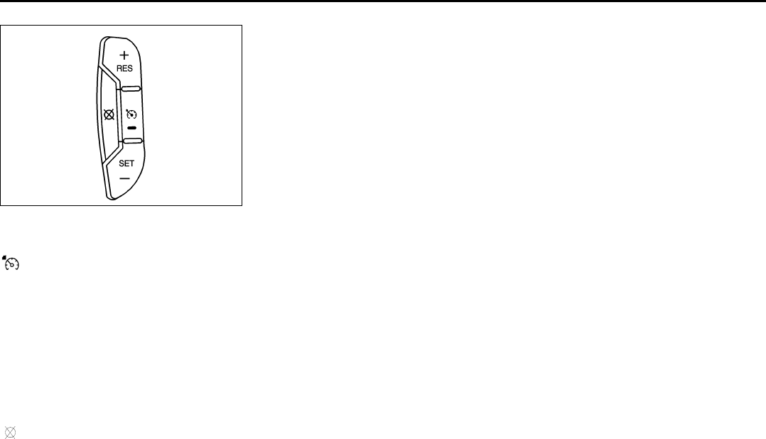
3-6
INSTRUMENT PANEL
78J00-03E
1541871
The cruise control buttons are located on
the left side of the steering wheel.
(On/Off):
Press this button to turn the cruise control
system on and off. The indicator light is on
when cruise control is on and turns off
when cruise control is off.
+RES (Resume):
Press this button to resume a set speed
and to accelerate the speed.
SET– (Set):
Press this button to set a speed and to
decrease the speed.
(Cancel):
Press this button to cancel cruise control
without erasing the set speed from mem-
ory.
Setting Cruise Control
The cruise control light on the instrument
panel cluster will come on after the cruise
control has been set to the desired speed.
1) Press the on/off button to turn cruise
control on.
2) Get up to the speed you want.
3) Press the SET– button and release it.
4) Take your foot off the accelerator pedal.
When the brakes are applied, the cruise
control shuts off.
If the vehicle is in cruise control and the
Traction Control System (TCS) begins to
limit wheel spin, the cruise control will
automatically disengage. Refer to “Traction
Control System (TCS)” in “Your Driving,
the Road, and Your Vehicle” in the “Driving
Your Vehicle” section. When road condi-
tions allow, the cruise control can be used
again.
Resuming a Set Speed
Suppose you set your cruise control at a
desired speed and then you apply the
brakes. This shuts off the cruise control.
The cruise symbol in the instrument panel
cluster will also go off indicating cruise is
no longer engaged. To return to your previ-
ously set speed, you do not need to go
through the set process again.
Once you are driving about 25 mph (40
km/h) or more, press the +RES button on
your steering wheel. The vehicle will go
back to the previous set speed and stay
there.
Increasing Speed While Using Cruise
Control
There are two ways to go to a higher
speed.
• Press and hold the +RES button on the
steering wheel until you reach your new
desired speed, then release it.
• To increase vehicle speed in small
amounts, press the +RES button. Each
time you do this, you will go about 1 mph
(1.6 km/h) faster.
Reducing Speed While Using Cruise
Control
To reduce your speed while using cruise
control:
• Press and hold the SET– button on the
steering wheel until the desired lower
speed is reached, then release it.
• To slow down in very small amounts,
push the SET– button on the steering
wheel briefly. Each time you do this, the
vehicle will go about 1 mph (1.6 km/h)
slower.
Passing Another Vehicle While Using
Cruise Control
Use the accelerator pedal to increase your
speed. When you take your foot off the
pedal, your vehicle will slow down to the
cruise control speed you set earlier. How-
ever, if you use the accelerator to increase

3-7
INSTRUMENT PANEL
78J00-03E
the vehicle’s speed for approximately 60
seconds, cruise control will disengage.
Using Cruise Control on Hills
How well your cruise control will work on
hills depends upon your speed, load, and
the steepness of the hills. When going up
steep hills, you may have to step on the
accelerator pedal to maintain your vehi-
cle’s speed. When going downhill, you may
have to brake or shift to a lower gear to
limit the vehicle’s speed. Of course, apply-
ing the brakes ends cruise control. Many
drivers find this to be too much trouble and
do not use cruise control on steep hills.
Ending Cruise Control
There are three ways to end cruise control:
• Step lightly on the brake pedal.
• Press the cancel button on the steering
wheel.
• Press the On/Off button on the steering
wheel.
Erasing Speed Memory
When the cruise control or the ignition is
turned off, the cruise control set speed
memory is erased.
Headlamps
The exterior lamp control is located on the
turn signal/multifunction lever.
(Exterior Lamp Control):
Turn the control with this symbol on it to
operate the exterior lamps.
The exterior lamp control has the following
positions:
AUTO (Off/Automatic Headlamps):
Turn the control to this position to put the
headlamps in automatic mode. Automatic
mode will turn the exterior lamps on and off
depending upon how much light is avail-
able outside of the vehicle.
(Parking Lamps):
Turn the control to this position to turn on
the parking lamps together with the follow-
ing:
• Sidemarker Lamps
• Taillamps
• License Plate Lamps
• Instrument Panel Lights
(Headlamps):
Turning the control to this position turns on
the headlamps, together with the previ-
ously listed lamps and lights.
Headlamps on Reminder
If you open the driver’s door with the igni-
tion off and the lamps on, you will hear a
warning chime.
Daytime Running Lamps (DRL)
Daytime Running Lamps (DRL) can make
it easier for others to see the front of your
vehicle during the day. DRL can be helpful
in many different driving conditions, but
they can be especially helpful in the short
periods after dawn and before sunset.
Fully functional daytime running lamps are
required on all vehicles first sold in Can-
ada.
A light sensor on top of the instrument
panel makes the DRL work, so be sure it is
not covered.
The DRL system’s automatic headlamp
control will make the low-beam headlamps
come on at a reduced brightness when the
following conditions are met:
• The ignition is in RUN.
• The exterior lamps control is in AUTO.
• The engine is running.
When the DRL are on, only the low-beam
headlamps, at a reduced level of bright-
ness, will be on. The headlamps, taillamps,
sidemarker, and other lamps will not be on.
The instrument panel and cluster will also
not be lit.
When it is dark enough outside, the DRL
will turn off and the headlamps and parking
lamps will turn on. The other lamps that
come on with the headlamps will also
come on.
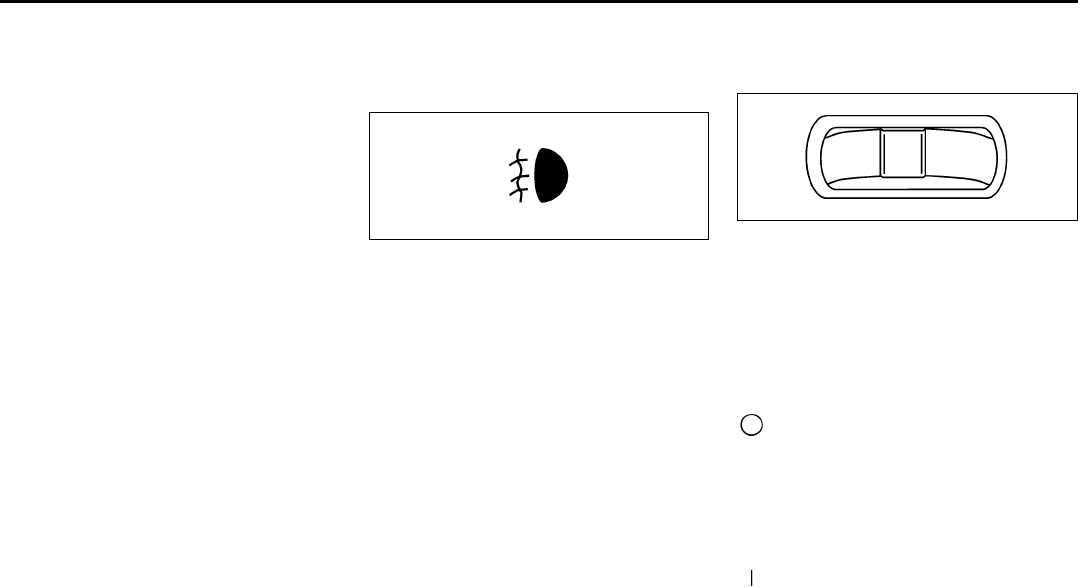
3-8
INSTRUMENT PANEL
78J00-03E
When it is bright enough outside, the head-
lamps will go off and the DRL will come on.
As with any vehicle, you should turn on the
regular headlamp system when you need
it.
Automatic Headlamp System
When it is dark enough outside and the
exterior lamps control is in the automatic
position, the headlamps will come on auto-
matically. Refer to “Headlamps” in this sec-
tion.
Your vehicle has a light sensor located on
top of the instrument panel. Make sure it is
not covered, or the headlamps will be on
when you do not need them.
The system may also turn on the head-
lamps when driving through a parking
garage or tunnel.
Fog Lamps
If your vehicle has this feature, use your
fog lamps for better visibility in foggy or
misty conditions.
808603
The button for your fog lamps is located on
the center console; to the right of the rear
wipe and rear wash switches and above
the shift lever.
Push the button to turn the fog lamps on or
off.
When using fog lamps, the parking lamps
or low-beam headlamps must be on.
A light on the button will come on when the
fog lamps are on. Fog lamps will go off
whenever you turn the high-beam head-
lamps on. When the high-beam head-
lamps are turned off, the fog lamps will
come on again.
Some localities have laws that require the
headlamps to be on along with the fog
lamps.
Instrument Panel Brightness
This feature controls the brightness of the
instrument panel lights.
1788862
The control for this feature is located on
the instrument panel to the left of the steer-
ing column.
Turn the control to the right to brighten the
lights or to the left to dim them.
Dome Lamp
The dome lamp switch has three positions.
(Off):
The lamp will not come on as long as the
switch is in this position.
AUTO (Auto):
The lamp will come on when a door is
opened. Refer to “Entry Lighting” in this
section.
(On):
The lamp will stay on as long as the switch
is in this position.
Entry Lighting
If the dome lamp is in the AUTO position,
the dome lamp and the cargo lamp inside
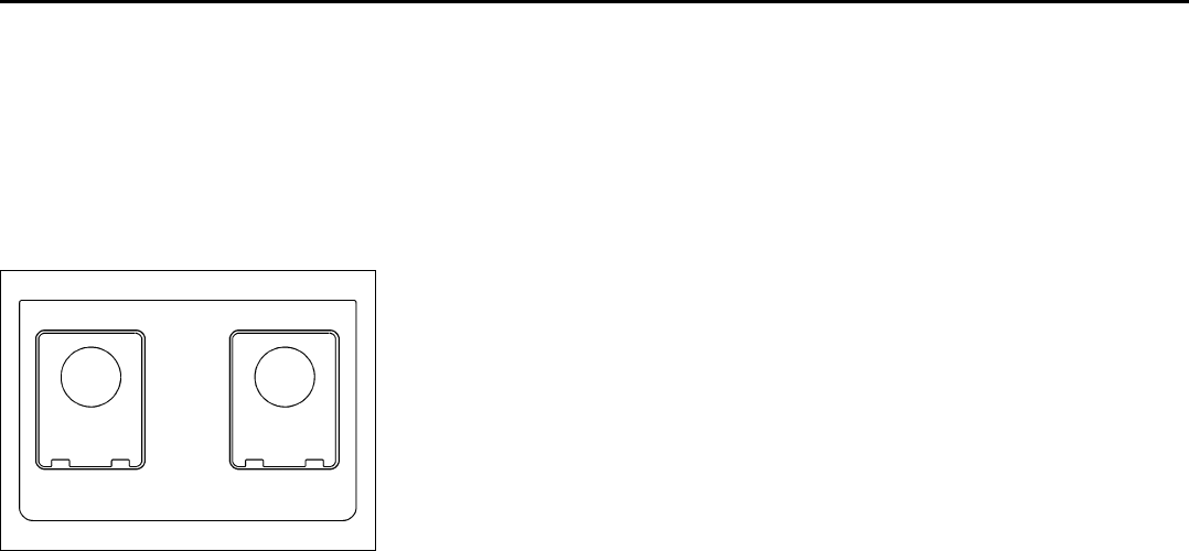
3-9
INSTRUMENT PANEL
78J00-03E
your vehicle will come on when any door is
opened. In addition, the light will come on
when the remote keyless entry unlock but-
ton is pressed. It will stay on for 20 sec-
onds or until a door is opened. After the
door is opened the light will remain on and
stay on for 20 seconds after the doors are
closed, or until you put the key in the igni-
tion and turn the key to RUN.
Map Lamps
1788863
Your vehicle may have lamps located on
the headliner above the rearview mirror.
Push on the lens in the lamp to turn them
on and off.
Cargo Lamp
The cargo lamp is located over the rear
compartment, and is controlled by the
dome lamp. Refer to “Dome Lamp” in this
section.
Electric Power Management
The vehicle has Electric Power Manage-
ment (EPM) that estimates the battery’s
temperature and state of charge. It then
adjusts the voltage for best performance
and extended life of the battery.
When the battery’s state of charge is low,
the voltage is raised slightly to quickly put
the charge back in. When the state of
charge is high, the voltage is lowered
slightly to prevent overcharging. If the vehi-
cle has a voltmeter gage or voltage display
on the Driver Information Center (DIC), you
may see the voltage move up or down.
This is normal. If there is a problem, an
alert will be displayed.
The battery can be discharged at idle if the
electrical loads are very high. This is true
for all vehicles. This is because the gener-
ator (alternator) may not be spinning fast
enough at idle to produce all the power
that is needed for very high electrical
loads.
A high electrical load occurs when several
of the following loads are on: headlamps,
high beams, fog lamps, rear window defog-
ger, climate control fan at high speed,
heated seats, engine cooling fans, trailer
loads, and loads plugged into accessory
power outlets.
EPM works to prevent excessive discharge
of the battery. It does this by balancing the
generator’s output and the vehicle’s electri-
cal needs. It can increase engine idle
speed to generate more power, whenever
needed. It can temporarily reduce the
power demands of some accessories.
Normally, these actions occur in steps or
levels, without being noticeable. In rare
cases at the highest levels of corrective
action, this action may be noticeable to the
driver. If so, a Driver Information Center
(DIC) message might be displayed, such
as Battery Saver Active or Service Battery
Charging System. If this message is dis-
played, it is recommended that the driver
reduce the electrical loads as much as
possible. Refer to “DIC Warnings and Mes-
sages” in this section.
Battery Run-Down Protection
Your vehicle has a battery saver feature
designed to protect the vehicle’s battery.
When any interior lamp is left on and the
ignition is turned off, the battery rundown
protection system will automatically turn
the lamp off after 20 minutes. This will
avoid draining the battery. This vehicle also
has a retained accessory power feature. If
the radio is on, it will turn off after 10 min-
utes or if any door on the vehicle is
opened. Refer to “Retained Accessory
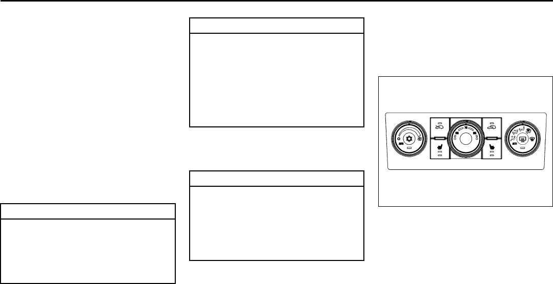
3-10
INSTRUMENT PANEL
78J00-03E
Power (RAP)” in “Starting and Operating
Your Vehicle” in the “Features and Con-
trols” section.
Accessory Power Outlet(s)
The accessory power outlets can be used
to connect electrical equipment such as a
cellular phone or CB radio.
Your vehicle may have four accessory
power outlets. They are located on the
instrument panel below the climate con-
trols, inside the front center console stor-
age bin under the cupholders, at the rear
of the center console, and in the rear cargo
area.
To use the outlets, remove the cover.
When not in use, always cover the outlet
with the protective cap.
Certain electrical accessories may not be
compatible with the accessory power out-
lets and could result in blown vehicle or
adapter fuses. If you experience a prob-
lem, see your dealer for additional informa-
tion on the accessory power outlet.
When adding electrical equipment, be sure
to follow the installation instructions
included with the equipment.
Climate Controls
Automatic Climate Control System
With this system you can control the heat-
ing, cooling, and ventilation for the vehicle.
Automatic Climate Control System
1824513
CAUTION
Leaving electrical equipment on for
extended periods will drain the bat-
tery. Always turn off electrical equip-
ment when not in use and do not plug
in equipment that exceeds the maxi-
mum amperage rating.
CAUTION
Adding any electrical equipment to
your vehicle may damage it or keep
other components from working as
they should. The repairs would not be
covered by your warranty. Do not use
equipment exceeding maximum
amperage rating of 20 amperes.
Check with your dealer before adding
electrical equipment.
CAUTION
Improper use of the power outlet can
cause damage not covered by your
warranty. Do not hang any type of
accessory or accessory bracket from
the plug because the power outlets
are designed for accessory power
plugs only.
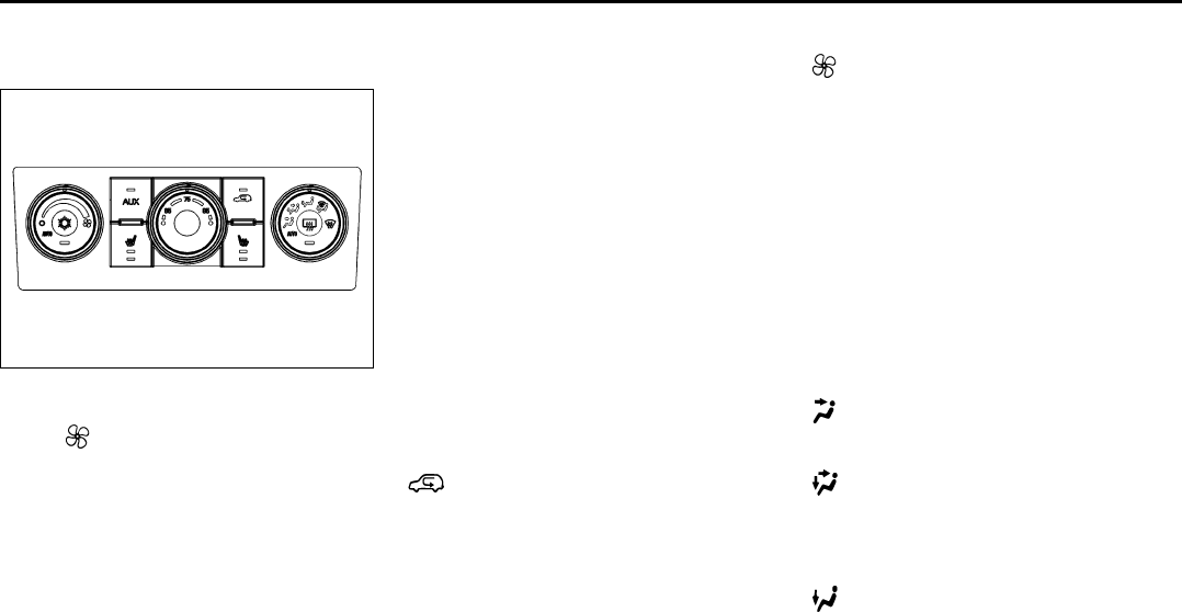
3-11
INSTRUMENT PANEL
78J00-03E
Automatic Climate Control System with
Rear Air Conditioning and Heating Sys-
tem
1732674
Automatic Operation
AUTO (Automatic Fan):
When this position is selected on the fan
control, the system automatically adjusts
the fan speed.
Temperature Setting:
The system uses the outside temperature,
passenger compartment air temperature,
and solar load sensors to maintain the
chosen temperature setting.
AUTO (Automatic Mode):
1) Turn the fan and mode control to the
AUTO position.
2) Adjust the temperature to a comfortable
setting between 31°F (16°C) and 89°F
(31°C). Choosing the coldest or warm-
est temperature setting does not cause
the system to heat or cool any faster. In
cold weather; the system starts at lower
fan speeds to avoid blowing cold air into
the vehicle until warmer air is available.
The system begins blowing air at the
floor, but can change modes automati-
cally as the vehicle warms up to main-
tain the chosen temperature setting.
The length of time needed to warm the
interior depends on the outside temper-
ature and temperature of the vehicle.
3) Wait 20 to 30 minutes for the system to
stabilize in order for the system to regu-
late automatically. Then adjust the tem-
perature as necessary to find your
comfort setting. Do not cover the solar
sensor located in the center of the
instrument panel near the windshield.
For more information on the solar sen-
sor, refer to “Sensors” later in this sec-
tion.
(AUTO RECIRCULATION):
Using the previous temperature setting,
the system automatically controls the air
inlet to supply fresh outside air or recircu-
late the interior air to cool the car faster.
The indicator light on the recirculation but-
ton lights whenever the system switches to
recirculation. Switch to outside air by
pressing the outside air button, if the vehi-
cle has a rear climate control system, or by
pressing the recirculation button. See AUX
for more information. The next time AUTO
fan or mode is selected, the air inlet resets
back to AUTO operation.
Manual Operation
(Fan):
Turn the left knob to increase or decrease
the fan speed. In any setting other than off,
the fan runs continuously with the ignition
on. To turn off the air completely, turn the
fan to 0 and select the recirculation button.
Temperature Control:
Turn the center knob to increase or
decrease the temperature inside your vehi-
cle.
Use the right knob to select from the fol-
lowing modes:
There is one position between each mode
to finely adjust airflow position.
(Vent):
This mode directs air to the instrument
panel outlets.
(Bi-Level):
This mode directs approximately half of the
air to the instrument panel outlets, and
then directs the remaining air to the floor
outlets.
(Floor):
This mode directs most of the air to the
floor outlets with some air directed to the
windshield and side window outlets.
The right knob can also be used to select
the defrost and defog modes that are
described in this section.
3-12
INSTRUMENT PANEL
78J00-03E
The modes can also be selected by press-
ing the following buttons:
AUX (Auxiliary):
This button is on a vehicle that has the
Rear Climate Control System. Press it to
turn on the rear heating and air condition-
ing. Refer to “Rear Air Conditioning and
Heating System” in this section for more
information.
(Outside Air):
Press this button to turn on the outside air
mode. While this mode is on, outside air
circulates throughout the vehicle. An indi-
cator light in the button comes on when
this button is pressed. The outside air
mode can be used with all modes, but it
cannot be used with the recirculation
mode.
(Recirculation):
Press this button to recirculate cabin air
through the vehicle. It can be used to pre-
vent outside air and odors from entering
the vehicle or to help heat or cool the air
inside the vehicle more quickly. An indica-
tor light above the symbol comes on in this
mode. Operation in this mode during peri-
ods of high humidity and cool outside tem-
peratures can result in increased window
fogging. If window fogging is experienced,
select the defrost mode.
The recirculation mode cannot be used
with outside air, floor, defog, or defrost
modes.
If your vehicle has a Rear Climate Control
System, use this button to switch between
outside air and recirculation.
(Air Conditioning):
Press this button to turn the air condition-
ing system on or off. When this button is
pressed, an indicator light on the button
comes on to let you know the air condition-
ing is activated.
On hot days, open the windows to let hot
inside air escape, then close them. This
helps to reduce the time it takes for the
vehicle to cool down. It also helps the sys-
tem to operate more efficiently.
The air conditioning system removes mois-
ture from the air, so you might notice a
small amount of water dripping underneath
the vehicle while idling or after turning off
the engine. This is normal.
(Heated Seats):
If your vehicle has heated seats, refer to
“Heated Seats” in the “Seats and Restraint
Systems” section for more information.
Defogging and Defrosting
Fog or frost on the inside of windows is a
result of high humidity (moisture) condens-
ing on the cool window glass. This can be
minimized if the climate control system is
used properly. To avoid fogging windows
on rainy and humid days at temperatures
above freezing, run the air conditioning
compressor. It is best to avoid the use of
the recirculation mode, except when maxi-
mum A/C performance is needed or for
short times to avoid exterior odors.
Use the floor/defog mode to clear the win-
dows of fog or moisture and warm the pas-
sengers. Use the defrost mode to remove
fog or frost from the windshield more
quickly.
When either of these modes or the floor
mode is selected, the system runs the air
conditioning compressor and cancels recir-
culation mode to dry the air; however, the
recirculation light stays on. For best
results, clear all snow and ice from the
windshield before defrosting.
Turn the right knob to select the defog or
defrost mode.
(Floor/Defog):
This mode directs about half of the air to
the floor outlets and the remaining air to
the windshield and the side window out-
lets.
(Defrost):
This mode directs most of the air to the
windshield and the side window outlets.
Rear Window Defogger
The rear window defogger uses a warming
grid to remove fog from the rear window.
The rear window defogger only works
when the ignition is in RUN.
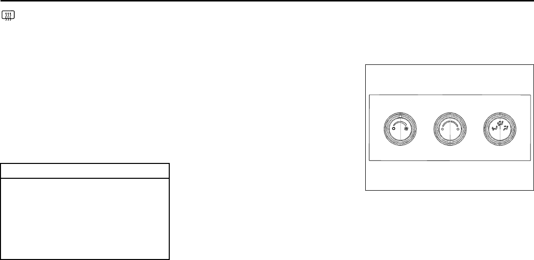
3-13
INSTRUMENT PANEL
78J00-03E
(Rear):
Press this button to turn the rear window
defogger on or off. An indicator light on the
button comes on to let you know that the
rear window defogger is activated.
The rear window defogger only works
when the ignition is in RUN. The rear win-
dow defogger stays on for approximately
15 minutes after the button is pressed,
unless the ignition is turned to ACC or
LOCK. If turned on again, the defogger
only runs for about five minutes before
turning off. The defogger can also be
turned off by pressing the button again or
by turning off the engine.
Outlet Adjustment
Use the louvers located on the air outlets
to change the direction of the airflow.
Operation Tips
• Clear away any ice, snow, or leaves from
the air inlets at the base of the vehicle
that may block the flow of air into your
vehicle.
• Do not use any non-SUZUKI approved
hood deflectors that could adversely
affect the performance of the system.
• Keep the path under the front seats clear
of objects to help circulate the air inside
of your vehicle more effectively.
Rear Air Conditioning and Heating
System
If your vehicle has this system, the rear
controls are three knobs located on the
rear of the center floor console. The sys-
tem can be controlled from the front con-
trols as well as the rear controls.
To turn the system on, press the AUX but-
ton on the front climate control system, an
indicator light will be lit. Pressing the AUX
button the first time will turn the rear sys-
tem on in a mimic mode. In this mode, the
airflow in the rear will be similar to the air-
flow direction, temperature, and fan speed
of the front controls. The rear system can
be turned off by pressing the AUX button
again or by turning the rear fan control
knob counterclockwise all the way.
If the rear controls are adjusted after the
AUX button is pressed, the system will
enter a rear independent mode. Airflow in
the rear is then directed according to the
settings of the rear controls.
1732690
Fan Knob
Turn the left knob clockwise or counter-
clockwise to increase or decrease the fan
speed. Turn the knob all the way counter-
clockwise to turn the rear system off.
Temperature Knob
The middle knob on the control panel lets
you select the temperature of the air flow-
ing into the passenger area. Turn the knob
clockwise toward the red area for warmer
air. Turn the knob counterclockwise toward
the blue area for cooler air.
CAUTION
Do not use anything sharp on the
inside of the rear window. If you do,
you could cut or damage the warm-
ing grid, and the repairs would not be
covered by your warranty. Do not
attach a temporary vehicle license,
tape, a decal or anything similar to
the defogger grid.
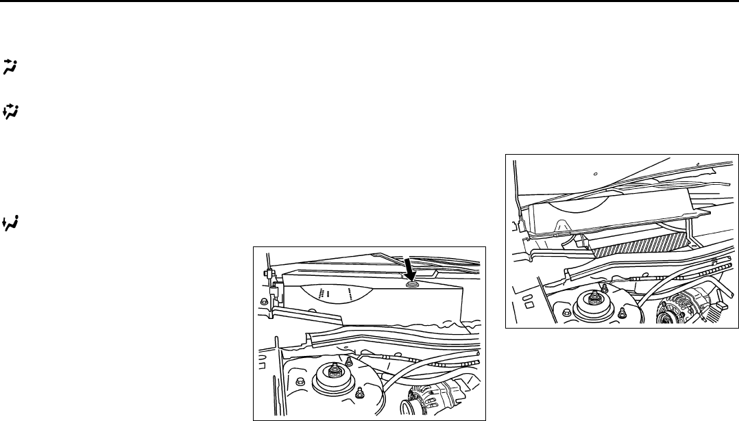
3-14
INSTRUMENT PANEL
78J00-03E
Mode Knob
The right knob on the control panel lets
you to choose the direction of air delivery.
(Vent):
This setting directs the air through the
headliner outlets.
(Bi-Level):
This setting directs the air through the floor
outlets, as well as the headliner outlets.
The rear system floor outlets are located
near third row seats. The flow can be
divided between vent and floor outlets
depending upon where the knob is placed
between the settings.
(Floor):
This setting directs most of the air through
the floor outlets. The rear system floor out-
lets are located near third row seats.
Passenger Compartment Air Filter
Outside air is routed through a passenger
compartment air filter before entering the
vehicle. This filter removes certain parti-
cles from the air, including pollen and dust
particles. Reductions in airflow, which may
occur more quickly in dusty areas, indicate
that the filter needs to be replaced early.
The filter should be replaced as part of
routine scheduled maintenance. Refer to
“Scheduled Maintenance” in “Mainte-
nance Schedule” in the “Maintenance
Schedule” section for when to replace the
filter.
To change the passenger compartment air
filter, use the following steps:
1580378
1) Remove the push pins from the rear of
the passenger’s side air inlet panel. It is
located in the rear of the engine com-
partment on the passenger side of the
vehicle.
2) Open the hood.
3) Remove the push pins from the top and
forward edge of the passenger’s side
air inlet panel.
4) Remove the air inlet panel.
5) Remove the filter from the filter housing
by pressing the release tab at the
inboard edge of the filter housing.
1394346
6) Remove the filter from the vehicle.
7) Install a new passenger compartment
air filter. For the type of filter to use refer
to “Normal Maintenance Replacement
Parts” in “Maintenance Schedule” in the
“Maintenance Schedule” section.
8) Reverse Steps 1 through 5.
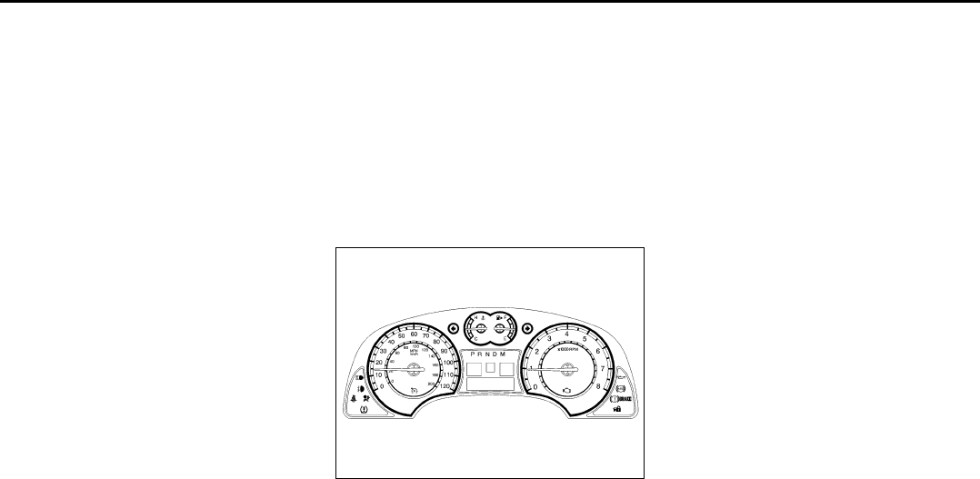
3-15
INSTRUMENT PANEL
78J00-03E
Warning Lights, Gages, and
Indicators
This part describes the warning lights and
gages that may be on your vehicle. The
pictures will help you locate them.
Warning lights and gages can signal that
something is wrong before it becomes seri-
ous enough to cause an expensive repair
or replacement. Paying attention to your
warning lights and gages could also save
you or others from injury.
Warning lights come on when there may
be or is a problem with one of your vehi-
cle’s functions. As you will see in the
details on the following pages, some warn-
ing lights come on briefly when you start
the engine just to let you know they are
working. If you are familiar with this sec-
tion, you should not be alarmed when this
happens.
Gages can indicate when there may be or
is a problem with one of your vehicle’s
functions. Often gages and warning lights
work together to let you know when there
is a problem with your vehicle.
When one of the warning lights comes on
and stays on when you are driving, or
when one of the gages shows there may
be a problem, check the section that tells
you what to do about it. Please follow this
manual’s advice. Waiting to do repairs can
be costly and even dangerous. So please
get to know your warning lights and gages.
They are a big help.
Instrument Panel Cluster
Your instrument panel cluster is designed
to let you know at a glance how your vehi-
cle is running. You will know how fast you
are going, how much fuel you are using,
and many other things you will need to
drive safely and economically.
United States version shown,
Canada similar
1716507
Speedometer and Odometer
Your speedometer lets you see your speed
in both miles per hour (mph) and kilome-
ters per hour (km/h).
Your odometer shows how far your vehicle
has been driven, in either miles (used in
the United States) or kilometers (used in
Canada).
Your vehicle has a tamper resistant odom-
eter. The digital odometer will read 999999
if someone tries to turn it back.
You may wonder what happens if your
vehicle needs a new odometer installed. If
the new one can be set to the mileage total
of the old odometer, then it must be. If not,
then it is set at zero and a label must be
put on the driver’s door to show the old
mileage reading when the new odometer
was installed.
Trip Odometer
Your trip odometer is located in the Driver
Information Center and shows how far your
vehicle has been driven since the trip
odometer was last reset. For more infor-
mation refer to “DIC Operation and Dis-
plays” in this section.
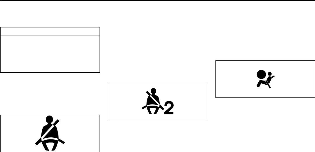
3-16
INSTRUMENT PANEL
78J00-03E
Tachometer
The tachometer shows your engine speed
in revolutions per minute (rpm).
Safety Belt Reminder Light
When the key is turned to RUN or START,
a chime will come on for several seconds
to remind people to fasten their safety
belts, unless the driver’s safety belt is
already buckled.
808234
The safety belt light will also come on and
stay on for several seconds, then it will
flash for several more.
If the driver’s belt is already buckled, nei-
ther the chime nor the light will come on.
Passenger Safety Belt Reminder
Light
Several seconds after the key is turned to
RUN or START, a chime will sound for sev-
eral seconds to remind the front passenger
to buckle their safety belt. This would only
occur if the passenger airbag is enabled.
Refer to “Passenger Sensing System” in
“Airbag System” in the “Seats and
Restraint Systems” section for more infor-
mation. The passenger safety belt light will
also come on and stay on for several sec-
onds, then it will flash for several more.
1468137
This chime and light will be repeated if the
passenger remains unbuckled and the
vehicle is in motion.
If the passenger’s safety belt is buckled,
neither the chime nor the light will come
on.
Airbag Readiness Light
There is an airbag readiness light on the
instrument panel, which shows the airbag
symbol. The system checks the airbag’s
electrical system for malfunctions. The
light tells you if there is an electrical prob-
lem. The system check includes the airbag
sensor, the airbag modules, the wiring and
the crash sensing and diagnostic module.
808322
This light will come on when you start your
vehicle, and it will flash for a few seconds.
Then the light should go out. This means
the system is ready.
If the airbag readiness light stays on after
you start the vehicle or comes on when
you are driving, your airbag system may
not work properly. Have your vehicle ser-
viced right away.
CAUTION
If you operate the engine with the
tachometer in the solid red area, your
vehicle could be damaged. The dam-
ages would not be covered by your
warranty. Do not operate the engine
in the solid red area.
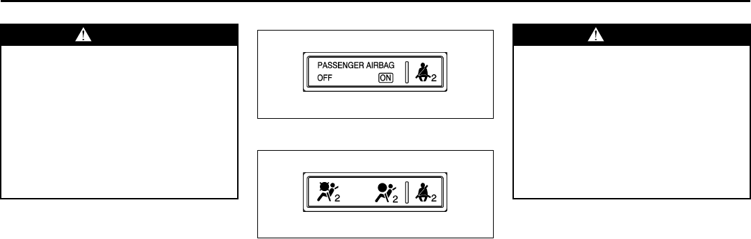
3-17
INSTRUMENT PANEL
78J00-03E
The airbag readiness light should flash for
a few seconds when you turn the ignition
key to RUN. If the light does not come on
then, have it fixed so it will be ready to
warn you if there is a problem.
Passenger Airbag Status Indicator
Your vehicle has the passenger sensing
system. Your instrument panel has a pas-
senger airbag status indicator.
United States
1476572
Canada
1476529
When the ignition key is turned to RUN or
START, the passenger airbag status indi-
cator will light ON and OFF, or the symbol
for on and off, for several seconds as a
system check. Then, after several more
seconds, the status indicator will light
either ON or OFF, or either the on or off
symbol to let you know the status of the
right front passenger’s frontal airbag.
There is a label on your sun visor that
says, “Never put a rear-facing child seat in
the front.” This is because the risk to the
rear-facing child is so great if the airbag
deploys.
If your vehicle does not have a rear seat
that will accommodate a rear-facing child
restraint, never put a child in a rear-facing
child restraint in the right front passenger
seat unless the passenger airbag status
indicator shows off and the airbag is off.
Here is why:
WARNING
If the airbag readiness light stays on
after you start your vehicle, it means
the airbag system may not be work-
ing properly. The airbags in your
vehicle may not inflate in a crash, or
they could even inflate without a
crash. To help avoid injury to yourself
or others, have your vehicle serviced
right away if the airbag readiness
light stays on after you start your
vehicle.
WARNING
Even though the passenger sensing
system is designed to turn off the
passenger’s frontal airbag if the sys-
tem detects a rear-facing child
restraint, no system is fail-safe, and
no one can guarantee that an airbag
will not deploy under some unusual
circumstance, even though it is
turned off. We recommend that rear-
facing child restraints be secured in
the rear seat, even if the airbag is off.
3-18
INSTRUMENT PANEL
78J00-03E
If the word ON or the on symbol is lit on the
passenger airbag status indicator, it means
that the right front passenger’s frontal air-
bag is enabled (may inflate).
If the word OFF or the off symbol is lit on
the airbag status indicator, it means that
the passenger sensing system has turned
off the right front passenger’s frontal air-
bag. Refer to “Passenger Sensing System”
in “Airbag System” in the “Seats and
Restraint Systems” section for more on
this, including important safety information.
If, after several seconds, all status indicator
lights remain on, or if there are no lights at
all, there may be a problem with the lights
or the passenger sensing system. See
your dealer for service.
WARNING
Even though the passenger sensing
system is designed to turn off the
passenger’s frontal airbag if the sys-
tem detects a rear-facing child
restraint, no system is fail-safe, and
no one can guarantee that an airbag
will not deploy under some unusual
circumstance, even though it is
turned off. We recommend that rear-
facing child restraints be trans-
ported in vehicles with a rear seat
that will accommodate a rear-facing
child restraint, whenever possible.
WARNING
If the on indicator comes on when
you have a rear-facing child restraint
installed in the right front passen-
ger’s seat, it means that the passen-
ger sensing system has not turned
off the passenger’s frontal airbag. A
child in a rear-facing child restraint
can be seriously injured or killed if
the right front passenger’s airbag
inflates. This is because the back of
the rear-facing child restraint would
be very close to the inflating airbag.
Do not use a rear-facing child
restraint in the right front passen-
ger’s seat if the airbag is turned on.
WARNING
If the off indicator and the airbag
readiness light ever come on
together, it means that something
may be wrong with the airbag sys-
tem. If this ever happens, have the
vehicle serviced promptly, because
an adult-size person sitting in the
right front passenger seat may not
have the protection of the frontal air-
bag. Refer to “Airbag Readiness
Light” in this section.
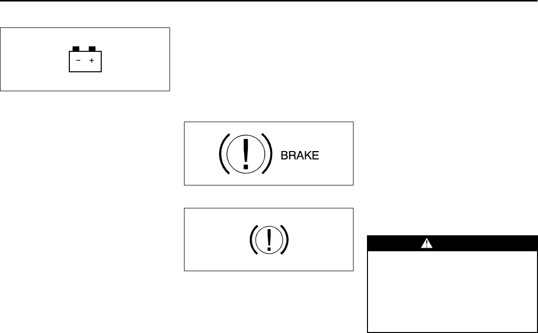
3-19
INSTRUMENT PANEL
78J00-03E
Battery Warning Light
812700
Your vehicle has a battery warning light.
If this light comes on while you are driving,
be sure to turn off accessories such as the
radio and climate control system. Have
your vehicle serviced right away. The SER-
VICE BATTERY CHARGING SYSTEM
message may also appear in the Driver
Information Center. Refer to “DIC Warn-
ings and Messages” in this section for
more information.
Brake System Warning Light
Your vehicle’s hydraulic brake system is
divided into two parts. If one part is not
working, the other part can still work and
stop you. For good braking, though, you
need both parts working well.
If the brake system warning light comes
on, there is a brake problem. Have your
brake system inspected right away.
United States
1240159
Canada
861215
The brake light is located in the instrument
panel cluster.
This light should come on briefly when you
turn the ignition key to RUN. If it does not
come on then, have it fixed so it will be
ready to warn you if there is a problem.
When the ignition is on, the brake light will
come on when you set your parking brake.
The light will stay on if your parking brake
does not release fully. A chime will also
sound if the parking brake is not fully
released and the vehicle is moving. If it
stays on after your parking brake is fully
released, it means you have a brake prob-
lem.
The brake light will also come on to indi-
cate a low brake fluid level. Refer to
“Brakes” in “Checking Things Under the
Hood” in the “Service and Appearance
Care” section for more information.
If the light comes on while you are driving,
pull off the road and stop carefully. You
may notice that the pedal is harder to push
or the pedal may go closer to the floor. It
may take longer to stop. If the light is still
on, have the vehicle towed for service.
Refer to “Towing Your Vehicle” in “Towing”
in the “Driving Your Vehicle” section.
WARNING
Your brake system may not be work-
ing properly if the brake system
warning light is on. Driving with the
brake system warning light on can
lead to an accident. If the light is still
on after you have pulled off the road
and stopped carefully, have the vehi-
cle towed for service.
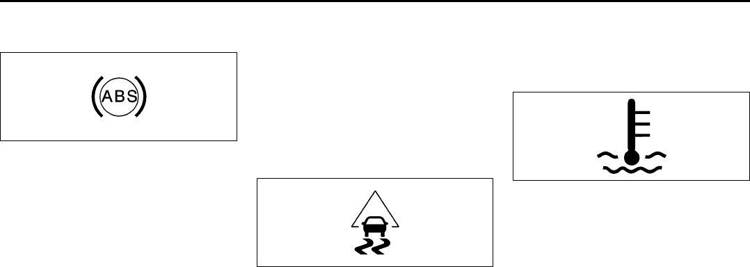
3-20
INSTRUMENT PANEL
78J00-03E
Anti-Lock Brake System Warning
Light
807057
With the Anti-Lock Brake System (ABS),
the light will come on when your engine is
started and stay on for several seconds.
This is normal.
If the ABS warning light comes on and
stays on, there may be a problem with the
anti-lock portion of the brake system. If the
brake system warning light is not on, you
still have brakes, but you do not have anti-
lock brakes. Refer to “Brake System Warn-
ing Light” in this section for more informa-
tion.
If the light stays on, turn the ignition to
LOCK. If the light comes on when you are
driving, stop as soon as possible and turn
the ignition off. Then start the engine again
to reset the system. If the light still stays
on, or comes on again while you are driv-
ing, your vehicle needs service. If the regu-
lar brake system warning light is not on,
you still have brakes, but you do not have
anti-lock brakes. If the regular brake sys-
tem warning light is also on, you do not
have anti-lock brakes and there is a prob-
lem with your regular brakes. Refer to
“Brake System Warning Light” in this sec-
tion for more information.
The ABS warning light should come on
briefly when you turn the ignition key to
RUN. If the light does not come on then,
have it fixed so it will be ready to warn you
if there is a problem.
Traction Control System (TCS)
Warning Light
1545635
Your vehicle has a traction control system
warning light.
This light will come on when your traction
control system is limiting wheel spin. You
may feel or hear the system working, but
this is normal. This light may also come on
after extended heavy braking indicating the
brakes have become too hot to limit wheel
spin.
If the traction control system warning light
comes on and stays on for an extended
period of time when the system is turned
on, your vehicle needs service. Refer to
“Traction Control System (TCS)” in “Your
Driving, the Road, and Your Vehicle” in the
“Driving Your Vehicle” section for more
information.
Engine Coolant Temperature
Warning Light
808241
The engine coolant temperature warning
light will come on when the engine has
overheated.
If this happens you should pull over and
turn off the engine as soon as possible.
Refer to “Engine Overheating” in “Check-
ing Things Under the Hood” in the “Service
and Appearance Care” section for more
information.
NOTE:
Driving with the engine coolant tempera-
ture warning light on could cause your
vehicle to overheat. Refer to “Engine Over-
heating” in “Checking Things Under the
Hood” in the “Service and Appearance
Care” section. Your vehicle could be dam-
aged, and it might not be covered by your
warranty. Never drive with the engine cool-
ant temperature warning light on.
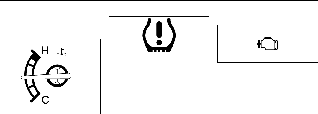
3-21
INSTRUMENT PANEL
78J00-03E
This light will also come on when starting
your vehicle. If it does not, have your vehi-
cle serviced.
Engine Coolant Temperature Gage
1716501
This gage shows the engine coolant tem-
perature. If the pointer moves towards the
H, the engine is too hot.
A temperature indicator light will turn on
and a chime will sound.
If you have been operating your vehicle
under normal driving conditions, and the
temperature indicator light comes on, you
should pull off the road, stop your vehicle
and turn off the engine as soon as possi-
ble.
Tire Pressure Light
1198521
This light will come on briefly when you
turn the ignition to RUN.
This light will also come on when one or
more of your tires are significantly underin-
flated.
A CHECK TIRE PRESSURE DIC mes-
sage will accompany the light.
Stop and check your tires as soon as it is
safe to do so. If underinflated, inflate to the
proper pressure. Refer to “Tires” in the
“Service and Appearance Care” section for
more information.
This light will flash for 60 seconds and then
turn on solid if a problem is detected with
the Tire Pressure Monitor system.
Refer to “Tire Pressure Monitor System” in
“Tires” in the “Service and Appearance
Care” section for more information.
Malfunction Indicator Lamp
Check Engine Light
805353
Your vehicle has a computer which moni-
tors operation of the fuel, ignition, and
emission control systems.
This system is called OBD II (On-Board
Diagnostics-Second Generation) and is
intended to assure that emissions are at
acceptable levels for the life of the vehicle,
helping to produce a cleaner environment.
The check engine light comes on to indi-
cate that there is a problem and service is
required. Malfunctions often will be indi-
cated by the system before any problem is
apparent. This may prevent more serious
damage to your vehicle. This system is
also designed to assist your service techni-
cian in correctly diagnosing any malfunc-
tion.

3-22
INSTRUMENT PANEL
78J00-03E
This light should come on, as a check to
show you it is working, when the ignition is
on and the engine is not running. If the
light does not come on, have it repaired.
This light will also come on during a mal-
function in one of two ways:
•Light Flashing
A misfire condition has been detected. A
misfire increases vehicle emissions and
may damage the emission control sys-
tem on your vehicle. Diagnosis and ser-
vice may be required.
•Light On Steady
An emission control system malfunction
has been detected on your vehicle. Diag-
nosis and service may be required.
If the Light is Flashing
The following may prevent more serious
damage to your vehicle:
• Reducing vehicle speed
• Avoiding hard accelerations
• Avoiding steep uphill grades
• If you are towing a trailer, reduce the
amount of cargo being hauled as soon
as it is possible
If the light stops flashing and remains on
steady, see “If the Light Is On Steady” fol-
lowing.
If the light continues to flash, when it is
safe to do so, stop the vehicle. Find a safe
place to park your vehicle. Turn the key off,
wait at least 10 seconds and restart the
engine. If the light remains on steady, see
“If the Light Is On Steady” following. If the
light is still flashing, follow the previous
steps, and see your dealer for service as
soon as possible.
If the Light Is On Steady
You may be able to correct the emission
system malfunction by considering the fol-
lowing:
Did you recently put fuel into your vehicle?
If so, reinstall the fuel cap, making sure to
fully install the cap. Refer to “Filling the
Tank” in “Fuel” in the “Service and Appear-
ance Care” section. The diagnostic system
can determine if the fuel cap has been left
off or improperly installed. A loose or miss-
ing fuel cap will allow fuel to evaporate into
the atmosphere. A few driving trips with the
cap properly installed should turn the light
off.
Did you just drive through a deep puddle of
water?
If so, your electrical system may be wet.
The condition will usually be corrected
when the electrical system dries out. A few
driving trips should turn the light off.
Have you recently changed brands of fuel?
If so, be sure to fuel your vehicle with qual-
ity fuel. Refer to “Gasoline Octane” in
“Fuel” in the “Service and Appearance
Care” section. Poor fuel quality will cause
your engine not to run as efficiently as
designed. You may notice this as stalling
after start-up, stalling when you put the
vehicle into gear, misfiring, hesitation on
CAUTION
If you keep driving your vehicle with
this light on, after awhile, the emis-
sion controls might not work as well,
your vehicle’s fuel economy might
not be as good, and the engine might
not run as smoothly. This could lead
to costly repairs that might not be
covered by your warranty.
CAUTION
Modifications made to the engine,
transaxle, exhaust, intake, or fuel
system of your vehicle or the replace-
ment of the original tires with other
than those of the same Tire Perfor-
mance Criteria (TPC) can affect your
vehicle’s emission controls and may
cause this light to come on. Modifica-
tions to these systems could lead to
costly repairs not covered by your
warranty. This may also result in a
failure to pass a required Emission
Inspection/Maintenance test. Refer to
“Accessories and Modifications” in
“Service” in the “Service and
Appearance Care” section.
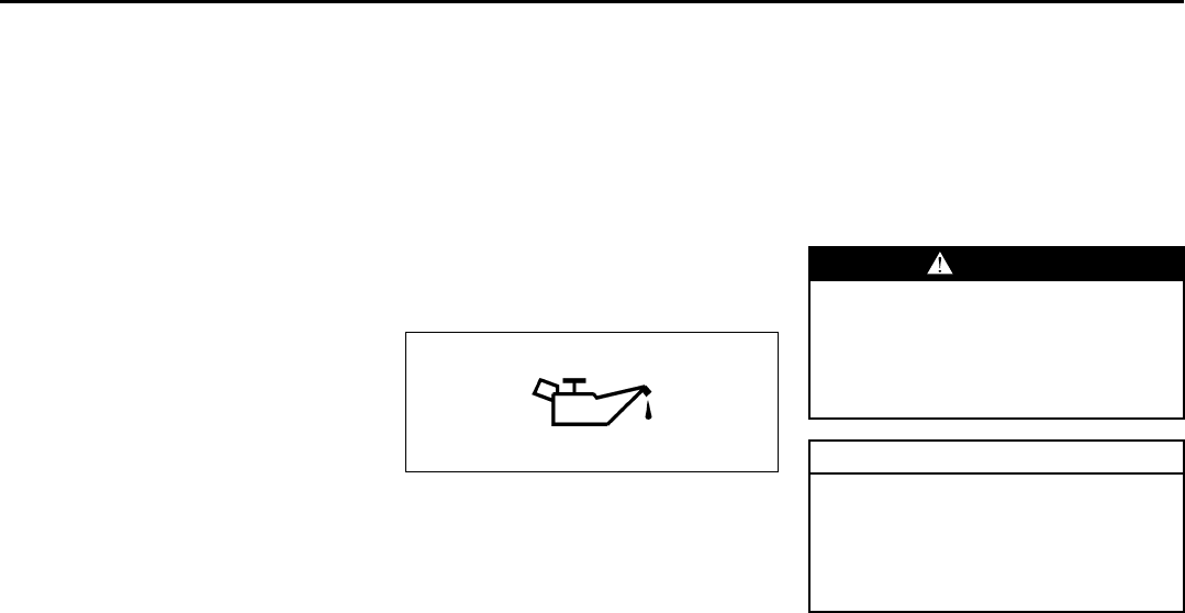
3-23
INSTRUMENT PANEL
78J00-03E
acceleration, or stumbling on acceleration.
(These conditions may go away once the
engine is warmed up.) This will be
detected by the system and cause the light
to turn on.
If you experience one or more of these
conditions, change the fuel brand you use.
It will require at least one full tank of the
proper fuel to turn the light off.
If none of the above steps have made the
light turn off, your dealer can check the
vehicle. Your dealer has the proper test
equipment and diagnostic tools to fix any
mechanical or electrical problems that may
have developed.
Emissions Inspection and Maintenance
Programs
Some state/provincial and local govern-
ments have or may begin programs to
inspect the emission control equipment on
your vehicle. Failure to pass this inspection
could prevent you from getting a vehicle
registration.
Here are some things you need to know to
help your vehicle pass an inspection:
Your vehicle will not pass this inspection if
the check engine light is on or not working
properly.
Your vehicle will not pass this inspection if
the OBD (on-board diagnostic) system
determines that critical emission control
systems have not been completely diag-
nosed by the system. The vehicle would be
considered not ready for inspection. This
can happen if you have recently replaced
your battery or if your battery has run
down. The diagnostic system is designed
to evaluate critical emission control sys-
tems during normal driving. This may take
several days of routine driving. If you have
done this and your vehicle still does not
pass the inspection for lack of OBD system
readiness, your dealer can prepare the
vehicle for inspection.
Oil Pressure Light
808235
If you have a low engine oil pressure prob-
lem, this light will stay on after you start
your engine, or come on when you are
driving. This indicates that your engine is
not receiving enough oil.
The engine could be low on oil, or could
have some other oil problem. Have it fixed
immediately.
The oil light could also come on in three
other situations:
• When the ignition is on but the engine is
not running, the light will come on as a
test to show you it is working, but the
light will go out when you turn the igni-
tion to START. If it does not come on with
the ignition on, you may have a problem
with the fuse or bulb. Have it fixed right
away.
• If the vehicle is idling at a stop sign, the
light may blink on and then off.
• If you make a hard stop, the light may
come on for a moment. This is normal.
WARNING
Do not keep driving if the oil pressure
is low. If you do, your engine can
become so hot that it catches fire.
You or others could be burned. Check
your oil as soon as possible and have
your vehicle serviced.
CAUTION
Lack of proper engine oil mainte-
nance may damage the engine. The
repairs would not be covered by your
warranty. Always follow the mainte-
nance schedule in this manual for
changing engine oil.
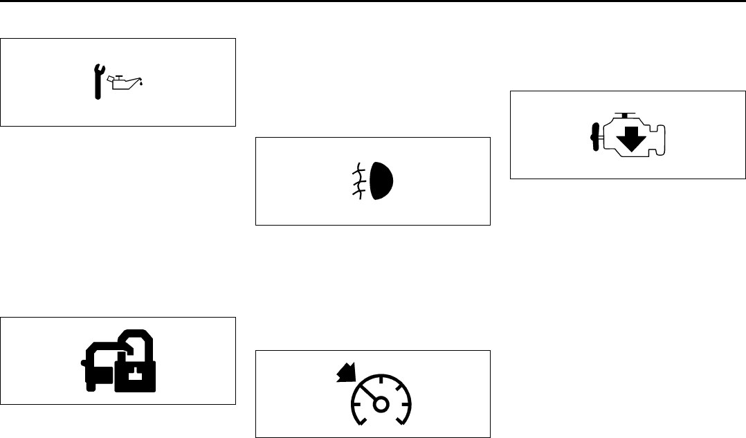
3-24
INSTRUMENT PANEL
78J00-03E
Change Engine Oil Light
806876
If this light comes on and stays on for 30
seconds, it means that service is required
for your vehicle.
After having the oil changed you will need
to reset the light. Refer to “Engine Oil” in
“Checking Things Under the Hood” in the
“Service and Appearance Care” and
“Scheduled Maintenance” in “Mainte-
nance Schedule” in the “Maintenance
Schedule” section for more information.
Security Light
811473
Your vehicle has a theft-deterrent system.
With this system, the security light will
flash as you open the door if your ignition
is off.
This light will come on briefly when the
vehicle is turned on.
For more information, refer to “PASS-Key®
III+ Operation” in “Theft-Deterrent Sys-
tems” in the “Features and Controls” sec-
tion.
Fog Lamp Light
808603
The fog lamp light will come on when the
fog lamps are in use.
The light will go out when the fog lamps
are turned off. Refer to “Fog Lamps” in this
section for more information.
Cruise Control Light
806861
This light comes on whenever you set the
cruise control.
The light goes out when the cruise control
is turned off. Refer to “Cruise Control” in
this section for more information.
Reduced Engine Power Light
1278022
Your vehicle has a reduced engine power
light.
This light, along with the service vehicle
soon light, will be displayed when a notice-
able reduction in the vehicle’s performance
may occur. Stop the vehicle and turn off
the ignition. Wait for 10 seconds and
restart your vehicle. This may correct the
condition. Refer to “Service Vehicle Soon
Light” in this section for more information.
The vehicle may be driven at a reduced
speed when the reduced engine power
light is on, but acceleration and speed may
be reduced. The performance may be
reduced until the next time you drive your
vehicle. If this light stays on, see your
SUZUKI dealer as soon as possible for
diagnosis and repair.
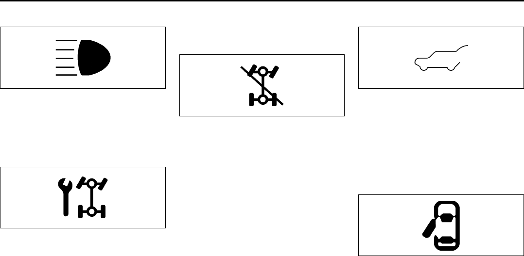
3-25
INSTRUMENT PANEL
78J00-03E
Highbeam On Light
808597
This light comes on when the high-beam
headlamps are in use.
Refer to “Headlamp High/Low-Beam
Changer” in this section.
Service All-Wheel Drive Light
1710820
This light is located in the center of your
instrument panel cluster.
This light and the SERVICE ALL WHEEL
DRIVE message in the Driver Information
Center (DIC) will come on and stay on to
indicate that there may be a problem with
the drive system and service is required.
Refer to “All-Wheel Drive (AWD) System”
in “Your Driving, the Road, and Your Vehi-
cle” in the “Driving Your Vehicle” section
and “DIC Warnings and Messages” in this
section for more information.
All-Wheel Drive Disabled Light
1710823
This light will come on when the rear drive
system is overheating.
An ALL WHEEL DRIVE OFF message will
appear in the Driver Information Center
(DIC) too. This light will turn off when the
rear drive system cools down. If this light
stays on for a while, you need to reset the
light. To reset the light, turn the ignition off
and then back on again. If the light stays
on, see your dealer right away.
Refer to “All-Wheel Drive” in the “Service
and Appearance Care” section and “DIC
Warnings and Messages” in this section for
more information.
Gate Ajar Light
1326999
If this light comes on, your liftgate is not
completely closed. Driving with the liftgate
open can cause carbon monoxide (CO) to
enter the vehicle.
Refer to “Engine Exhaust” in “Starting and
Operating Your Vehicle” in the “Features
and Controls” section for more information.
Door Ajar Light
1734979
This light will come on when a door is ajar.
Do not drive with a door ajar.
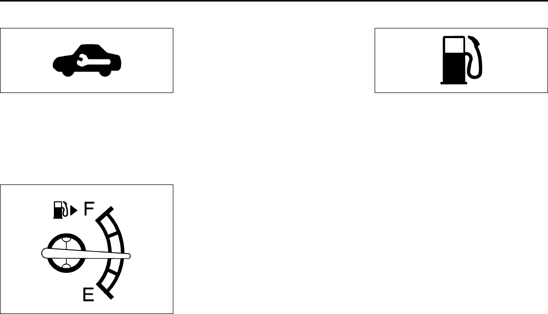
3-26
INSTRUMENT PANEL
78J00-03E
Service Vehicle Soon Light
1254434
This light will come on if a condition exists
that may require the vehicle to be taken in
for service.
If the light comes on, see your dealer for
service as soon as possible.
Fuel Gage
1716499
When the ignition is on, the fuel gage tells
you about how much fuel you have left in
your fuel tank.
When the indicator nears empty, the low
fuel light will come on. You still have a little
fuel left, but you should get more soon.
Refer to “Low Fuel Warning Light” in this
section for more information.
Here are four things that some owners ask
about. None of these show a problem with
your fuel gage:
• At the service station, the fuel pump
shuts off before the gage reads full.
• It takes a little more or less fuel to fill up
than the gage indicated. For example,
the gage may have indicated the tank
was half full, but it actually took a little
more or less than half the tank’s capacity
to fill the tank.
• The gage moves a little when you turn a
corner or speed up.
• The gage takes a few seconds to stabi-
lize after the ignition is turned on, and
will go back to empty when you turn the
ignition off.
For your fuel tank capacity, refer to “Capac-
ities and Specifications” in the “Service
and Appearance Care” section.
Low Fuel Warning Light
1406936
This light is located below the fuel gage.
This light also comes on when the fuel tank
is low on fuel. When you add fuel the light
should go off. If it does not, have your vehi-
cle serviced.
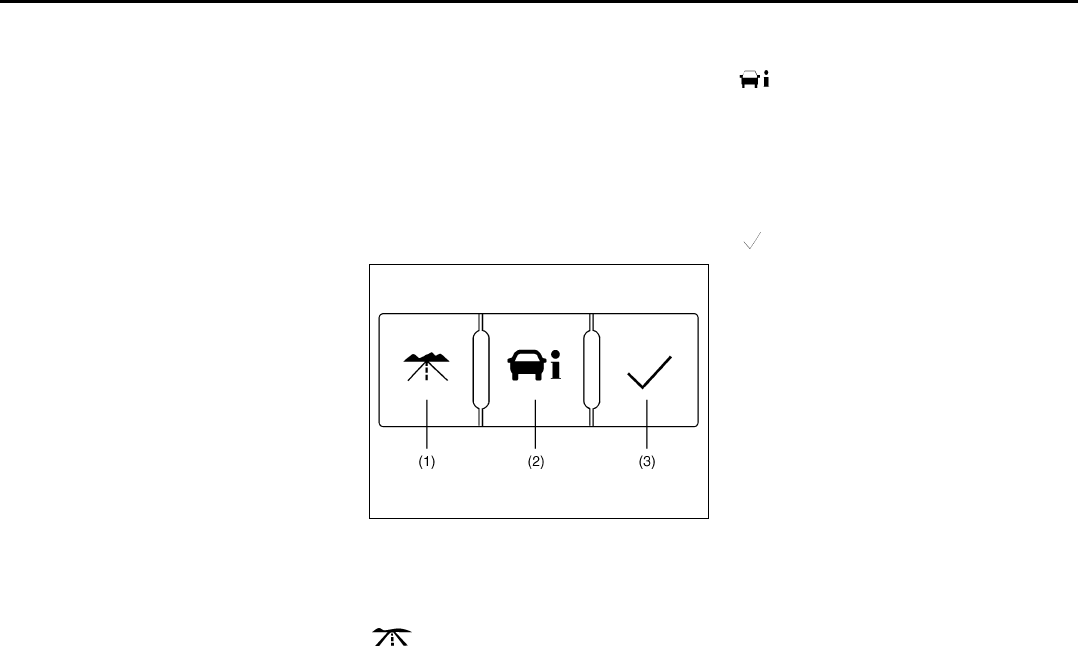
3-27
INSTRUMENT PANEL
78J00-03E
Driver Information Center
(DIC)
Your vehicle has a Driver Information Cen-
ter (DIC).
All messages will appear in the DIC display
located in the center of the instrument
panel cluster. The DIC buttons are located
on the center of the instrument panel.
The DIC comes on when the ignition is on.
After a short delay, the DIC will display the
information that was last displayed before
the engine was turned off.
The DIC displays trip, fuel, and vehicle sys-
tem information, and warning messages if
a system problem is detected. The top of
the DIC display shows the shift lever posi-
tion indicator. Refer to “Automatic Tran-
saxle Operation” in “Starting and
Operating Your Vehicle” in the “Features
and Controls” section for more information.
If your vehicle has this feature, the DIC
also displays the outside air temperature
when viewing the trip and fuel information.
If there is a problem with the system that
controls the temperature display, the num-
bers will be replaced with dashes. If this
occurs, have the vehicle serviced by your
dealer. If an abnormal temperature reading
is displayed for an extended period of time,
consult your dealer. Under certain circum-
stances, especially when the engine is
idling, a delay updating the temperature
display is normal.
The DIC also allows some features to be
personalized. Refer to “DIC Vehicle Per-
sonalization” in this section for more infor-
mation.
DIC Operation and Displays
The DIC has different displays which can
be accessed by pressing the DIC buttons
located on the center of the instrument
panel.
DIC Buttons
1657854
The buttons are the trip/fuel, vehicle infor-
mation, and set/reset buttons. The button
functions are detailed in the following
pages.
Trip/Fuel (1):
Press this button to scroll through the trip
and fuel displays. See “Trip/Fuel Menu
Items” following for more information on
these displays.
Vehicle Information (2):
Press this button to scroll through the vehi-
cle information displays and to personalize
the feature settings on your vehicle. Refer
to “Vehicle Information Menu Items” follow-
ing and “DIC Vehicle Personalization” in
this section for more information on these
displays.
Set/Reset (3):
Press this button to set or reset certain
functions and to turn off or acknowledge
messages on the DIC.

3-28
INSTRUMENT PANEL
78J00-03E
Trip/Fuel Menu Items
Trip/Fuel (1):
Press this button to scroll through the fol-
lowing displays:
ODOMETER
Press the trip/fuel button until ODOMETER
displays. This display shows the distance
the vehicle has been driven in either miles
(mi) or kilometers (km). This display will
also show the outside air temperature in
either degrees Fahrenheit (°F) or degrees
Celsius (°C).
To change the DIC display to English or
metric units, refer to “UNITS” later in this
section.
TRIP
Press the trip/fuel button until TRIP dis-
plays. This display shows the current dis-
tance traveled in either miles (mi) or
kilometers (km) since the last reset for the
trip odometer. This display will also show
the outside air temperature in either
degrees Fahrenheit (°F) or degrees Cel-
sius (°C).
The trip odometer can be reset to zero by
pressing the set/reset button while the trip
odometer is displayed.
AVERAGE SPEED
Press the trip/fuel button until AVERAGE
SPEED displays. This display shows the
average speed of the vehicle in miles per
hour (mph) or kilometers per hour (km/h).
This average is calculated based on the
various vehicle speeds recorded since the
last reset of this value. To reset the value,
press and hold the set/reset button. The
display will return to zero.
AVG (Average) ECONOMY
Press the trip/fuel button until AVG ECON-
OMY displays. This display shows the
approximate average miles per gallon
(mpg) or liters per 100 kilometers (L/100
km). This number is calculated based on
the number of mpg (L/100 km) recorded
since the last time this menu item was
reset. To reset this display, press and hold
the set/reset button. The display will return
to zero.
RANGE
Press the trip/fuel button until RANGE dis-
plays. This display shows the approximate
number of remaining miles (mi) or kilome-
ters (km) the vehicle can be driven without
refueling.
The fuel range estimate is based on an
average of the vehicle’s fuel economy over
recent driving history and the amount of
fuel remaining in the fuel tank. This esti-
mate will change if driving conditions
change. For example, if driving in traffic
and making frequent stops, this display
may read one number, but if the vehicle is
driven on a freeway, the number may
change even though the same amount of
fuel is in the fuel tank. This is because dif-
ferent driving conditions produce different
fuel economies. Generally, freeway driving
produces better fuel economy than city
driving.
If your vehicle is low on fuel, the FUEL
LEVEL LOW message will be displayed.
Refer to “FUEL LEVEL LOW” under “DIC
Warnings and Messages” in this section for
more information.
Blank Display
This display shows no information.

3-29
INSTRUMENT PANEL
78J00-03E
Vehicle Information Menu Items
Vehicle Information (2):
Press this button to scroll through the fol-
lowing displays:
OIL LIFE
Press the vehicle information button until
OIL LIFE REMAINING displays. This dis-
play shows an estimate of the oil’s remain-
ing useful life. If you see 99% OIL LIFE
REMAINING on the display, that means
99% of the current oil life remains. The
engine oil life system will alert you to
change your oil on a schedule consistent
with your driving conditions.
When the remaining oil life is low, the
CHANGE ENGINE OIL SOON message
will appear on the display. Refer to
“CHANGE ENGINE OIL SOON” under
“DIC Warnings and Messages” in this sec-
tion. You should change your oil as soon
as possible. Refer to “Engine Oil” in
“Checking Things Under the Hood” in the
“Service and Appearance Care” section. In
addition to the engine oil life system moni-
toring the oil life, additional maintenance is
recommended in the Maintenance Sched-
ule in this manual. Refer to “Scheduled
Maintenance” in “Maintenance Schedule”
in the “Maintenance Schedule” section for
more information.
Remember, you must reset the OIL LIFE
yourself after each oil change. It will not
reset itself. Also, be careful not to reset the
OIL LIFE accidentally at any time other
than when the oil has just been changed. It
cannot be reset accurately until the next oil
change. To reset the engine oil life system,
refer to “Engine Oil Life System” in “Check-
ing Things Under the Hood” in the “Service
and Appearance Care” section.
UNITS
Press the vehicle information button until
UNITS displays. This display allows you to
select between English or Metric units of
measurement. Once in this display, press
the set/reset button to select between
ENGLISH or METRIC units.
FRONT TIRES or REAR TIRES
The pressure for each tire can be viewed in
the DIC. The tire pressure will be shown in
either pounds per square inch (psi) or kilo-
pascals (kPa). Press the vehicle informa-
tion button until the DIC shows FRONT
TIRES PSI (kPa) LF ## (###) RF ## (###).
Press the vehicle information button again
until the DIC displays REAR TIRES PSI
(kPa) LR ## (###) RR ## (###).
If a low or high tire pressure condition is
detected by the system while driving, a
message advising you to check the pres-
sure in a specific tire will appear in the dis-
play. Refer to “Inflation - Tire Pressure” in
“Tires” in the “Service and Appearance
Care” section and “DIC Warnings and
Messages” in this section for more infor-
mation.
If the tire pressure display shows dashes
instead of a value, there may be a problem
with your vehicle. If this consistently
occurs, see your dealer for service.
BATTERY
Press the vehicle information button until
BATTERY displays. This display shows the
current battery voltage. If the voltage is
low, the display will show LOW. If the volt-
age is high, the display will show HIGH.
Your vehicle’s charging system regulates
voltage based on the state of the battery.
The battery voltage may fluctuate when
viewing this information on the DIC. This is
normal. Refer to “Battery Warning Light” in
this section for more information.
If there is a problem with the battery charg-
ing system, the DIC will display SERVICE
BATTERY CHARGING SYSTEM. Refer to
“SERVICE BATTERY CHARGING SYS-
TEM” under “DIC Warnings and Mes-
sages” in this section. Also, refer to
“Electric Power Management” in this sec-
tion for more information.
TIRE LOCATIONS
After rotating the tires or after replacing a
tire or sensor, the system must re-learn the
tire positions. To re-learn the tire positions,
refer to “Tire Pressure Monitor System” in
“Tires” in the “Service and Appearance
Care” section. Refer to “Tire Inspection
and Rotation” in “Tires” in the “Service and
Appearance Care” section and “DIC Warn-
ings and Messages” in this section for
more information.

3-30
INSTRUMENT PANEL
78J00-03E
RELEARN REMOTE KEY
This display allows you to match the
Remote Keyless Entry (RKE) transmitter to
your vehicle. To match a RKE transmitter
to your vehicle, do the following:
1) Make sure the vehicle is in PARK (P).
2) Press the vehicle information button
until PRESS TO RELEARN
REMOTE KEY displays.
3) Press the set/reset button.
The message REMOTE KEY LEARN-
ING ACTIVE will display.
4) Press and hold the lock and unlock but-
tons on the first transmitter at the same
time for about 15 seconds.
A chime will sound indicating that the
transmitter is matched.
5) To match additional transmitters at this
time, repeat Step 3.
Each vehicle can have a maximum of
four transmitters matched to it.
6) To exit the programming mode, you
must cycle the key to LOCK.
Blank Display
This display shows no information.
PERSONALIZATION
This display allows you to personalize the
feature settings on your vehicle. Refer to
“DIC Vehicle Personalization” in this sec-
tion for more information.
DIC Warnings and Messages
Messages are displayed on the DIC to
notify the driver that the status of the vehi-
cle has changed and that some action may
be needed by the driver to correct the con-
dition. Multiple messages may appear one
after another. Some messages may not
require immediate action, but you can
press the set/reset button to acknowledge
that you received the messages and to
clear them from the display. Pressing any
of the DIC buttons also acknowledge and
clear any messages. Some messages
cannot be cleared from the DIC display
because they are more urgent. These
messages require action before they can
be cleared. You should take any messages
that appear on the display seriously and
remember that clearing the messages will
only make the messages disappear, not
correct the problem. The following are the
possible messages that can be displayed
and some information about them.
ALL WHEEL DRIVE OFF
If your vehicle has the All-Wheel Drive
(AWD) system, this message displays
along with the All-Wheel Drive Disabled
light when the rear drive system is over-
heating. This message turns off when the
rear drive system cools down. If the warn-
ing message stays on for a while, you need
to reset the warning message. To reset the
warning message, turn the ignition off and
then back on again. If the message stays
on, see your dealer right away. Refer to
“All-Wheel Drive (AWD) System” in “Your
Driving, the Road, and Your Vehicle” in the
“Driving Your Vehicle” section and “All-
Wheel Drive Disabled Light” in this section
for more information.
BATTERY SAVER ACTIVE
This message displays when the charging
system detects that the battery is being
drained. You may notice that the vehicle
attempts to reduce the drain for you by
turning off accessories, such as interior
fans, rear defogger, and heated seats. Turn
off all accessories. If the vehicle is not run-
ning, start and run the engine for at least
10 minutes to allow the battery to
recharge. If the engine is running and the
condition persists, see your dealer immedi-
ately.
BUCKLE PASSENGER SEATBELT
This message reminds you to buckle the
passenger’s safety belt. Refer to “Passen-
ger Sensing System” in “Airbag System” in
the “Seats and Restraint Systems” section.
This message displays and a chime
sounds when the ignition is on, the driver’s
safety belt is buckled, the passenger’s
safety belt is unbuckled with the passenger
airbag enabled, and the vehicle is in
motion. You should have the passenger
buckle their safety belt.
This reminder will be repeated if the igni-
tion is on, the vehicle is in motion, the
driver is buckled and the passenger is still
unbuckled, and the passenger airbag is

3-31
INSTRUMENT PANEL
78J00-03E
enabled. If the passenger’s safety belt is
already buckled, this message and chime
will not come on.
BUCKLE SEATBELT
This message reminds you to buckle the
driver’s safety belt.
This message displays and a chime
sounds when the ignition is on, the driver’s
safety belt is unbuckled, and the vehicle is
in motion. You should buckle your safety
belt.
If the driver remains unbuckled when the
ignition is on and the vehicle is in motion,
the reminder will be repeated. If the driver’s
safety belt is already buckled, this mes-
sage and chime will not come on.
This message is an additional reminder to
the Safety Belt Reminder Light in the
instrument panel cluster. Refer to “Safety
Belt Reminder Light” in this section.
CHANGE ENGINE OIL SOON
This message displays when service is
required for the vehicle. See your dealer.
Refer to “Engine Oil” in “Checking Things
Under the Hood” in the “Service and
Appearance Care” section and “Scheduled
Maintenance” in “Maintenance Schedule”
in the “Maintenance Schedule” section for
more information.
Acknowledging this message will not reset
the OIL LIFE REMAINING display. That
must be done at the OIL LIFE screen
under the vehicle information menu. Refer
to “OIL LIFE” under “DIC Operation and
Displays” in this section and “Engine Oil
Life System” in “Checking Things Under
the Hood” in the “Service and Appearance
Care” section for more information.
CHECK TIRE PRESSURE
This message displays when the tire pres-
sure in one of the tires needs to be
checked. This message also displays
LEFT FRONT, RIGHT FRONT, LEFT
REAR, or RIGHT REAR to indicate which
tire needs to be checked. You can receive
more than one tire pressure message at a
time. To read the other messages that may
have been sent at the same time, press the
set/reset button. If a tire pressure message
appears on the DIC, stop as soon as you
can. Have the tire pressures checked and
set to those shown on the Tire Loading
Information label. Refer to “Tires” in the
“Service and Appearance Care” section,
“Loading Your Vehicle” in “Your Driving, the
Road, and Your Vehicle” in the “Driving
Your Vehicle” section, and “Inflation - Tire
Pressure” in “Tires” in the “Service and
Appearance Care” section. The DIC dis-
play also shows the tire pressure values for
the front and rear tires by pressing the
vehicle information button. Refer to “DIC
Operation and Displays” in this section. If
the tire pressure is low, the low tire pres-
sure warning light comes on. Refer to “Tire
Pressure Light” in this section.
DRIVER DOOR OPEN
This message displays when the driver’s
door is not closed properly. When this
message appears, make sure that the
driver’s door is closed completely.
ENGINE HOT A/C (Air Conditioning)
OFF
This message displays when the engine
coolant becomes hotter than the normal
operating temperature. To avoid added
strain on a hot engine, the air conditioning
compressor is automatically turned off.
When the coolant temperature returns to
normal, the A/C operation automatically
resumes. You can continue to drive your
vehicle.
ENGINE OVERHEATD (Overheated)
IDLE ENGINE
NOTE:
If you drive your vehicle while the engine is
overheating, severe engine damage may
occur. If an overheat warning appears on
the instrument panel cluster and/or DIC,
stop the vehicle as soon as possible. Do
not increase the engine speed above nor-
mal idling speed. Refer to “Engine Over-
heating” in “Checking Things Under the
Hood” in the “Service and Appearance
Care” section for more information.
This message displays when the engine
coolant temperature is too hot. Stop and
allow the vehicle to idle until it cools down.

3-32
INSTRUMENT PANEL
78J00-03E
ENGINE OVERHEATD (Overheated)
STOP ENGINE
NOTE:
If you drive your vehicle while the engine is
overheating, severe engine damage may
occur. If an overheat warning appears on
the instrument panel cluster and/or DIC,
stop the vehicle as soon as possible. Refer
to “Engine Overheating” in “Checking
Things Under the Hood” in the “Service
and Appearance Care” section for more
information.
This message displays along with a contin-
uous chime when the engine has over-
heated. Stop and turn the engine off
immediately to avoid severe engine dam-
age. Refer to “Engine Overheating” in
“Checking Things Under the Hood” in the
“Service and Appearance Care” section.
ENGINE POWER IS REDUCED
This message displays when the vehicle’s
engine power is reduced. Reduced engine
power can affect the vehicle’s ability to
accelerate. If this message is on, but there
is no reduction in performance, proceed to
your destination. The performance may be
reduced the next time the vehicle is driven.
The vehicle may be driven at a reduced
speed while this message is on, but accel-
eration and speed may be reduced. Any-
time this message stays on, the vehicle
should be taken to your dealer for service
as soon as possible.
FUEL LEVEL LOW
This message displays when your vehicle
is low on fuel. Refill the fuel tank as soon
as possible. Refer to “Fuel Gage” in this
section and “Filling the Tank” in “Fuel” in
the “Service and Appearance Care” sec-
tion for more information.
HOOD OPEN
This message displays on some vehicles
when the hood is not closed properly.
When this message appears, make sure
that the hood is closed completely. Refer to
“Hood Release” in “Checking Things
Under the Hood” in the “Service and
Appearance Care” section.
ICE POSSIBLE DRIVE WITH CARE
This message displays when the outside
air temperature is cold enough to create
icy road conditions. Adjust your driving
accordingly.
LIFTGATE OPEN
This message displays when the liftgate is
not closed completely. Make sure that the
liftgate is closed completely. Refer to “Lift-
gate” in “Doors and Locks” in the “Features
and Controls” section.
OIL PRSSURE (Pressure) LOW STOP
ENGINE
This message displays when the vehicle’s
engine oil pressure is low. The oil pressure
light also appears on the instrument panel
cluster. Refer to “Oil Pressure Light” in this
section.
Stop the vehicle immediately, as engine
damage can result from driving a vehicle
with low oil pressure. Have the vehicle ser-
viced by your dealer as soon as possible
when this message is displayed.
PASSENGER DOOR FRONT/REAR
OPEN
This message displays when one or more
of the passenger’s doors are not closed
properly. When this message appears,
make sure that all passenger doors are
closed completely.
CAUTION
If you drive your vehicle while the
engine oil pressure is low, severe
engine damage may occur. If a low oil
pressure warning appears on the
Driver Information Center (DIC), stop
the vehicle as soon as possible. Do
not drive the vehicle until the cause
of the low oil pressure is corrected.
Refer to “Engine Oil” in “Checking
Things Under the Hood” in the “Ser-
vice and Appearance Care” section
for more information.

3-33
INSTRUMENT PANEL
78J00-03E
REMOTE KEY LEARNING ACTIVE
This message displays while you are
matching a Remote Keyless Entry (RKE)
transmitter to your vehicle. Refer to
“LEARN REMOTE KEY” under “DIC Oper-
ation and Displays” in this section for more
information.
SERVICE A/C (Air Conditioning) SYS-
TEM
This message displays when there is a
problem detected in the air conditioning
system. Have the vehicle serviced by your
dealer.
SERVICE AIR BAG
This message displays when there is a
problem with the airbag system. Have your
vehicle serviced by your dealer immedi-
ately. Refer to “Airbag Readiness Light” in
this section for more information.
SERVICE ALL WHEEL DRIVE
If your vehicle has the All-Wheel Drive
(AWD) system, this message displays
along with the service all-wheel drive light
if a problem occurs with this system. Refer
to “Service All-Wheel Drive Light” in this
section. If this message appears, stop as
soon as possible and turn off the vehicle.
Restart the vehicle and check for the mes-
sage on the DIC display. If the message is
still displayed or appears again when you
begin driving, the AWD system needs ser-
vice. See your dealer.
SERVICE BATTERY CHARGING SYS-
TEM
This message displays when there is a
problem with the generator and battery
charging systems. Driving with this prob-
lem could drain the vehicle’s battery. Turn
off all unnecessary accessories. Stop and
turn off the vehicle as soon as it is safe to
do so. Have the electrical system checked
by your dealer immediately.
Connecting a battery charger to your vehi-
cle while the ignition is in any position
other than LOCK may cause this message
to appear. If you need to charge your vehi-
cle, make sure that the key is in LOCK or
out of the ignition during charging.
SERVICE BRAKE SYSTEM
This message displays and a chime
sounds when the brake fluid level is low.
The brake system warning light also
appears on the instrument panel cluster
when this message appears on the DIC.
Refer to “Brake System Warning Light” in
this section. Have the brake system ser-
viced by your dealer as soon as possible.
SERVICE STABILITY CTRL (Control)
This message displays if there has been a
problem detected with the Electronic Sta-
bility Control (ESC) system. A warning light
also appears on the instrument panel clus-
ter. Refer to “Traction Control System
(TCS) Warning Light” in this section. Refer
to “Electronic Stability Control” in “Your
Driving, the Road, and Your Vehicle” in the
“Driving Your Vehicle” section for more
information.
If this message turns on while you are driv-
ing, pull off the road as soon as possible
and stop carefully. Try resetting the system
by turning the ignition off and then back on.
If this message still stays on or turns back
on again while you are driving, your vehicle
needs service. Have the ESC system
inspected by your dealer as soon as possi-
ble.
SERVICE THEFT DETERRENT SYSTEM
This message displays when there is a
problem with the theft-deterrent system. A
fault has been detected in the system
which means that the system is disabled
and it is not protecting the vehicle. The
vehicle usually restarts; however, you may
want to take the vehicle to your dealer
before turning off the engine. Refer to
“PASS-Key® III+ Operation” in “Theft-
Deterrent Systems” in the “Features and
Controls” section for more information.
SERVICE TIRE MONITOR SYSTEM
This message displays if a part on the Tire
Pressure Monitor (TPM) system is not
working properly. If you drive your vehicle
while any of the four sensors are missing
or inoperable, the warning comes on in
about 20 minutes. A sensor would be miss-
ing, for example, if you put different wheels
on your vehicle without transferring the
sensors. If the warning comes on and

3-34
INSTRUMENT PANEL
78J00-03E
stays on, there may be a problem with the
TPM. See your dealer.
SERVICE TRACTION CONTROL
This message displays when the Traction
Control System (TCS) is not functioning
properly. A warning light also appears on
the instrument panel cluster. Refer to
“Traction Control System (TCS) Warning
Light” in this section and “Traction Control
System (TCS)” in “Your Driving, the Road,
and Your Vehicle” in the “Driving Your Vehi-
cle” section for more information. Have the
TCS serviced by your dealer as soon as
possible.
SERVICE VEHICLE SOON
This message displays when a non-emis-
sions related malfunction occurs. Have the
vehicle serviced by your dealer as soon as
possible.
STABILITY CTRL (Control) NOT READY
This message may display and a warning
light on the instrument panel cluster may
be on after first driving the vehicle and
exceeding 30 mph (48 km/h) for 30 sec-
onds. Refer to “Traction Control System
(TCS) Warning Light” in this section. The
Electronic Stability Control (ESC) system
is not functional until the light has turned
off. Refer to “Electronic Stability Control” in
“Your Driving, the Road, and Your Vehicle”
in the “Driving Your Vehicle” section for
more information.
STABILITY CTRL (Control) OFF
This message displays any time the Elec-
tronic Stability Control (ESC) system turns
off. When this message has been dis-
played, ESC is no longer available to assist
you with directional control of the vehicle.
Adjust your driving accordingly. Refer to
“Electronic Stability Control” in “Your Driv-
ing, the Road, and Your Vehicle” in the
“Driving Your Vehicle” section.
This message displays only while the igni-
tion is in RUN.
Any of the following conditions may cause
the ESC system to turn off:
• The ESC system is turned off by press-
ing and holding the traction control but-
ton. Refer to “Electronic Stability Control”
in “Your Driving, the Road, and Your
Vehicle” in the “Driving Your Vehicle”
section for more information.
• The battery is low.
• There is an ESC system failure. See
your dealer for service.
STARTING DISABLD (Disabled) SER-
VICE THRTTLE (Throttle)
This message displays if the starting of the
engine is disabled due to the electronic
throttle control system. Have your vehicle
serviced by your dealer immediately.
This message only appears while the igni-
tion is in RUN, and will not disappear until
the problem is resolved.
This message cannot be acknowledged.
THEFT ATTEMPTED
This message displays if the content theft-
deterrent system has detected a break-in
attempt while you were away from your
vehicle. Refer to “Content Theft-Deterrent”
in “Theft-Deterrent Systems” in the “Fea-
tures and Controls” section for more infor-
mation.
TIRE LEARNING ACTIVE
This message displays when the Tire Pres-
sure Monitor (TPM) system is re-learning
the tire positions. Refer to “Tire Pressure
Monitor System” in “Tires” in the “Service
and Appearance Care” section. The tire
positions must be re-learned after rotating
the tires or after replacing a tire or sensor.
Refer to “Tire Inspection and Rotation” and
“Inflation - Tire Pressure” in “Tires” in the
“Service and Appearance Care” section for
more information.
TRACTION CONTROL OFF
This message displays when the Traction
Control System (TCS) turns off. Refer to
“Traction Control System (TCS)” in “Your
Driving, the Road, and Your Vehicle” in the
“Driving Your Vehicle” section for more
information.
This message only displays while the igni-
tion is in RUN and disappears after 10 sec-
onds, unless it is acknowledged or an
urgent warning appears.
Any of the following conditions may cause
the TCS to turn off:

3-35
INSTRUMENT PANEL
78J00-03E
• The TCS is turned off by pressing the
traction control button. Refer to “Traction
Control System (TCS)” in “Your Driving,
the Road, and Your Vehicle” in the “Driv-
ing Your Vehicle” section for more infor-
mation.
• The battery is low.
• There is a TCS failure. See your dealer
for service.
TRACTION CONTROL ON
This message displays when the Traction
Control System (TCS) turns on. Refer to
“Traction Control System (TCS)” in “Your
Driving, the Road, and Your Vehicle” in the
“Driving Your Vehicle” section for more
information.
TURN SIGNAL ON
This message displays as a reminder to
turn off the turn signal if you drive your
vehicle for more than about 0.75 mile (1.2
km) with a turn signal on. Refer to “Turn
Signal/Multifunction Lever” in this section.
This message displays and a chime
sounds only when the ignition is in RUN.
The message will not disappear until the
turn signal is manually turned off, or a turn
is completed.
DIC Vehicle Personalization
Your vehicle has personalization capabili-
ties that allow you to program certain fea-
tures to one preferred setting.
All of the personalization options may not
be available on your vehicle. Only the
options available will be displayed on the
DIC.
The default settings for the personalization
features were set when your vehicle left
the factory, but may have been changed
from their default state since then.
The personalization preferences are auto-
matically recalled.
To change personalization preferences,
use the following procedure.
Entering the Feature Settings Menu
1) Turn the ignition on and place the vehi-
cle in PARK (P).
To avoid excessive drain on the battery,
it is recommended that the headlamps
are turned off.
2) Press the vehicle information button
until FEATURE SETTINGS PRESS
TO SELECT appears on the DIC dis-
play.
3) Press the set/reset button to enter the
feature settings menu.
If the menu is not available, FEATURE
SETTINGS AVAILABLE IN PRK (Park)
will display. Before entering the menu,
make sure the vehicle is in PARK (P).
Feature Settings Menu Items
The following are personalization features
that allow you to program settings to the
vehicle:
DISPLAY ENGLISH
This feature will only display if a language
other than English has been set. This fea-
ture allows you to change the language in
which the DIC messages appear to
English.
Press the vehicle information button until
the PRESS TO DISPLAY ENGLISH
screen appears on the DIC display. Press
the set/reset button to display all DIC mes-
sages in English.
DISPLAY LANGUAGE
This feature allows you to select the lan-
guage in which the DIC messages will
appear.
Press the vehicle information button until
DISPLAY LANGUAGE appears on the DIC
display. Press the set/reset button to
access the settings for this feature. Then
press the vehicle information button to
scroll through the following settings:
• ENGLISH (default):
All messages will appear in English.
• FRANCAIS (French):
All messages will appear in French.
• ESPANOL (Spanish):
All messages will appear in Spanish.

3-36
INSTRUMENT PANEL
78J00-03E
• NO CHANGE:
No change will be made to this feature.
The current setting will remain.
Choose one of the available settings and
press the set/reset button while it is dis-
played on the DIC to select it.
AUTO LOCK
This feature allows you to select when the
vehicle’s doors will automatically lock.
Refer to “Programmable Automatic Door
Locks” in “Doors and Locks” in the “Fea-
tures and Controls” section for more infor-
mation.
Press the vehicle information button until
AUTO LOCK appears on the DIC display.
Press the set/reset button to access the
settings for this feature. Then press the
vehicle information button to scroll through
the following settings:
• SHIFT OUT OF PARK (default):
The vehicle’s doors automatically lock
when the doors are closed and the vehi-
cle is shifted out of PARK (P).
• AT VEHICLE SPEED:
The vehicle’s doors automatically lock
when the vehicle speed is above 5 mph
(8 km/h) for three seconds.
• NO CHANGE:
No change will be made to this feature.
The current setting will remain.
Choose one of the available settings and
press the set/reset button while it is dis-
played on the DIC to select it.
AUTO UNLOCK
This feature allows you to select whether
or not to turn off the automatic door unlock-
ing feature. It also allows you to select
which doors and when the doors will auto-
matically unlock. Refer to “Programmable
Automatic Door Locks” in “Doors and
Locks” in the “Features and Controls” sec-
tion for more information.
Press the vehicle information button until
AUTO UNLOCK appears on the DIC dis-
play. Press the set/reset button to access
the settings for this feature. Then press the
vehicle information button to scroll through
the following settings:
•OFF:
None of the doors will automatically
unlock.
• DRIVER AT KEY OUT:
Only the driver’s door will unlock when
the key is taken out of the ignition.
• DRIVER IN PARK:
Only the driver’s door will unlock when
the vehicle is shifted into PARK (P).
• ALL AT KEY OUT:
All of the doors will unlock when the key
is taken out of the ignition.
• ALL IN PARK (default):
All of the doors will unlock when the
vehicle is shifted into PARK (P).
• NO CHANGE:
No change will be made to this feature.
The current setting will remain.
Choose one of the available settings and
press the set/reset button while it is dis-
played on the DIC to select it.
REMOTE LOCK
This feature allows you to select the type of
feedback you will receive when locking the
vehicle with the Remote Keyless Entry
(RKE) transmitter. You will not receive
feedback when locking the vehicle with the
RKE transmitter if any of the doors are
open. Refer to “Remote Keyless Entry
(RKE) System Operation” in “Keys” in the
“Features and Controls” section for more
information.
Press the vehicle information button until
REMOTE LOCK appears on the DIC dis-
play. Press the set/reset button to access
the settings for this feature. Then press the
vehicle information button to scroll through
the following settings:
•OFF:
There will be no feedback when you
press the lock button on the RKE trans-
mitter.
• LIGHTS ONLY:
The exterior lamps will flash when you
press the lock button on the RKE trans-
mitter.
• HORN ONLY:
The horn will sound on the second press
of the lock button on the RKE transmit-
ter.
• HORN & LIGHTS (default):
The exterior lamps will flash when you

3-37
INSTRUMENT PANEL
78J00-03E
press the lock button on the RKE trans-
mitter, and the horn will sound when the
lock button is pressed again within five
seconds of the previous command.
• NO CHANGE:
No change will be made to this feature.
The current setting will remain.
Choose one of the available settings and
press the set/reset button while it is dis-
played on the DIC to select it.
REMOTE UNLOCK
This feature allows you to select the type of
feedback you will receive when unlocking
the vehicle with the RKE transmitter. You
will not receive feedback when unlocking
the vehicle with the RKE transmitter if the
doors are open. Refer to “Remote Keyless
Entry (RKE) System Operation” in “Keys”
in the “Features and Controls” section for
more information.
Press the vehicle information button until
REMOTE UNLOCK appears on the DIC
display. Press the set/reset button to
access the settings for this feature. Then
press the vehicle information button to
scroll through the following settings:
• LIGHTS OFF:
The exterior lamps will not flash when
you press the unlock button on the RKE
transmitter.
• LIGHTS ON (default):
The exterior lamps will flash when you
press the unlock button on the RKE
transmitter.
• NO CHANGE:
No change will be made to this feature.
The current setting will remain.
Choose one of the available settings and
press the set/reset button while it is dis-
played on the DIC to select it.
DELAY LOCK
This feature allows you to select whether
or not the locking of the vehicle’s doors will
be delayed. The locking of the vehicle’s
doors is delayed for up to 10 seconds after
a power door lock switch is pressed when
a door is open, or after the lock button on
the RKE transmitter is pressed while a
door is open. The key must be out of the
ignition for this feature to work. Refer to
“Delayed Locking” in “Doors and Locks” in
the “Features and Controls” section for
more information.
Press the vehicle information button until
DELAY LOCK appears on the DIC display.
Press the set/reset button to access the
settings for this feature. Then press the
vehicle information button to scroll through
the following settings:
•OFF:
There will be no delayed locking of the
vehicle’s doors.
• ON (default):
The locking of the vehicle’s doors will be
delayed by 10 seconds after a power
door lock switch is pressed when a door
is open, or the lock button on the RKE
transmitter is pressed while a door is
open.
• NO CHANGE:
No change will be made to this feature.
The current setting will remain.
Choose one of the available settings and
press the set/reset button while it is dis-
played on the DIC to select it.
EXIT LIGHTING
If it is dark enough outside, this feature
allows you to select the amount of time you
want the exterior lamps to remain on. This
happens after the key is turned from RUN
to LOCK.
Press the vehicle information button until
EXIT LIGHTING appears on the DIC dis-
play. Press the set/reset button to access
the settings for this feature. Then press the
vehicle information button to scroll through
the following settings:
•OFF:
The exterior lamps will not turn on.
• 30 SECONDS (default):
The exterior lamps will stay on for 30
seconds.
• 1 MINUTE:
The exterior lamps will stay on for one
minute.
• 2 MINUTES:
The exterior lamps will stay on for two
minutes.
• NO CHANGE:
No change will be made to this feature.
The current setting will remain.

3-38
INSTRUMENT PANEL
78J00-03E
Choose one of the available settings and
press the set/reset button while it is dis-
played on the DIC to select it.
APPROACH LIGHTING
This feature allows you to select whether
or not to have the exterior lights turn on
briefly during low light periods after unlock-
ing the vehicle using the RKE transmitter.
Press the vehicle information button until
APPROACH LIGHTING appears on the
DIC display. Press the set/reset button to
access the settings for this feature. Then
press the vehicle information button to
scroll through the following settings:
•OFF:
The exterior lights will not turn on when
you unlock the vehicle with the RKE
transmitter.
• ON (default):
If it is dark enough outside, the exterior
lights will turn on briefly when you unlock
the vehicle with the RKE transmitter.
The lights will remain on for 20 seconds
or until the lock button on the RKE trans-
mitter is pressed, or the vehicle is no
longer off. Refer to “Remote Keyless
Entry (RKE) System Operation” in
“Keys” in the “Features and Controls”
section for more information.
• NO CHANGE:
No change will be made to this feature.
The current setting will remain.
Choose one of the available settings and
press the set/reset button while it is dis-
played on the DIC to select it.
CHIME VOLUME
This feature allows you to select the vol-
ume level of the chime.
Press the vehicle information button until
CHIME VOLUME appears on the DIC dis-
play. Press the set/reset button to access
the settings for this feature. Then press the
vehicle information button to scroll through
the following settings:
• NORMAL (default):
The chime volume will be set to a normal
level.
• LOUD:
The chime volume will be set to a loud
level.
• NO CHANGE:
No change will be made to this feature.
The current setting will remain.
Choose one of the available settings and
press the set/reset button while it is dis-
played on the DIC to select it.
REMOTE START
If your vehicle has this feature, it allows
you to turn the remote start off or on. The
remote start feature allows you to start the
engine from outside of the vehicle using
your RKE transmitter. Refer to “Remote
Vehicle Start” under “Remote Keyless
Entry (RKE) System Operation” in “Keys”
in the “Features and Controls” section for
more information.
Press the vehicle information button until
REMOTE START appears on the DIC dis-
play. Press the set/reset button to access
the settings for this feature. Then press the
vehicle information button to scroll through
the following settings:
•OFF:
The remote start feature will be disabled.
• ON (default):
The remote start feature will be enabled.
• NO CHANGE:
No change will be made to this feature.
The current setting will remain.
Choose one of the available settings and
press the set/reset button while it is dis-
played on the DIC to select it.
FACTORY SETTINGS
This feature allows you to set all of the per-
sonalization features back to their factory
default settings.
Press the vehicle information button until
FACTORY SETTINGS appears on the DIC
display. Press the set/reset button to
access the settings for this feature. Then
press the vehicle information button to
scroll through the following settings:
• RESTORE ALL (default):
The personalization features will be set
to their factory default settings.
3-39
INSTRUMENT PANEL
78J00-03E
• DO NOT RESTORE:
The personalization features will not be
set to their factory default settings.
Choose one of the available settings and
press the set/reset button while it is dis-
played on the DIC to select it.
EXIT FEATURE SETTINGS
This feature allows you to exit the feature
settings menu.
Press the vehicle information button until
FEATURE SETTINGS PRESS TO
EXIT appears in the DIC display. Press the
set/reset button to exit the menu.
If you do not exit, pressing the vehicle
information button again will return you to
the beginning of the vehicle information
menu.
Exiting the Feature Settings Menu
The feature settings menu will be exited
when any of the following occurs:
• The vehicle is shifted out of PARK (P).
• The vehicle is no longer in RUN.
• The trip/fuel DIC button is pressed.
• The end of the feature settings menu is
reached and exited.
• A 40 second time period has elapsed
with no selection made.
Audio System(s)
Determine which radio your vehicle has
and then read the pages following to famil-
iarize yourself with its features.
Driving without distraction is a necessity
for a safer driving experience. Refer to
“Defensive Driving” in “Your Driving, the
Road, and Your Vehicle” in the “Driving
Your Vehicle” section. By taking a few
moments to read this manual and get
familiar with your vehicle’s audio system,
you can use it with less effort, as well as
take advantage of its features. While your
vehicle is parked, set up your audio system
by presetting your favorite radio stations,
setting the tone and adjusting the speak-
ers. Then, when driving conditions permit,
you can tune to your favorite stations using
the presets and steering wheel controls if
the vehicle has them.
Keeping your mind on the drive is impor-
tant for safe driving. Here are some ways
in which you can help avoid distraction
while driving.
While your vehicle is parked:
• Familiarize yourself with all of its con-
trols.
• Familiarize yourself with its operation.
• Set up your audio system by presetting
your favorite radio stations, setting the
tone, and adjusting the speakers. Then,
when driving conditions permit, you can
tune to your favorite radio stations using
the presets and steering wheel controls
if the vehicle has them.
WARNING
This system provides you with a far
greater access to audio stations and
song listings. Giving extended atten-
tion to entertainment tasks while
driving can cause a crash and you or
others can be injured or killed.
Always keep your eyes on the road
and your mind on the drive – avoid
engaging in extended searching
while driving.
CAUTION
Before adding any sound equipment
to your vehicle, such as an audio
system, CD player, CB radio, mobile
telephone, or two-way radio, make
sure that it can be added by checking
with your dealer. Also, check federal
rules covering mobile radio and tele-
phone units. If sound equipment can
be added, it is very important to do it
properly. Added sound equipment
can interfere with the operation of
your vehicle’s engine, radio, or other
systems, and even damage them.
Your vehicle’s systems can interfere
with the operation of sound equip-
ment that has been added.

3-40
INSTRUMENT PANEL
78J00-03E
Your vehicle has a feature called Retained
Accessory Power (RAP). With RAP, the
audio system can be played even after the
ignition is turned off. Refer to “Retained
Accessory Power (RAP)” in “Starting and
Operating Your Vehicle” in the “Features
and Controls” section for more information.
Setting the Time (without date display)
If your vehicle has an AM/FM base radio
with a single CD player and preset buttons
numbered one through six, the radio will
have a clock button for setting the time.
You can set the time by following these
steps:
1) Press the clock button until the hour
numbers begin flashing on the display.
Press the clock button a second time
and the minute numbers will begin
flashing on the display.
2) While either the hour or the minute
numbers are flashing, turn the tune
knob, located on the upper right side of
the radio, clockwise or counterclock-
wise to increase or decrease the time.
Instead of using the tune knob, you can
also press the SEEK, FWD (forward),
or REV (reverse) buttons to adjust the
time.
3) Press the clock button again until the
clock display stops flashing to set the
currently displayed time; otherwise, the
flashing will stop after five seconds and
the current time displayed will be auto-
matically set.
To change the time default setting from 12
hour to 24 hour, press the clock button and
then the pushbutton located under the for-
ward arrow label. Once the time 12H and
24H are displayed, press the pushbutton
located under the desired option to select
the default. Press the clock button again to
apply the selected default, or let the screen
time out.
Setting the Time (with date display)
If your vehicle has a radio with a single CD
player or a CD with DVD player, the radio
will have a clock button for setting the time
and date.
To set the time and date, follow these
instructions:
1) Turn the radio on.
2) Press the clock button and the HR,
MIN, MM, DD, YYYY (hour, minute,
month, day, and year) will appear on the
display.
3) Press the pushbutton located under any
one of the labels that you want to
change. Every time the pushbutton is
pressed again, the time or the date if
selected, will increase by one.
– Another way to increase the time or
date, is to press the right SEEK arrow
or FWD (forward) button.
– To decrease, press the left SEEK
arrow or REV (reverse) button. You
can also turn the tune knob, located on
the upper right side of the radio, to
adjust the selected setting.
The date will not automatically display. The
only way to see the date is by pressing the
clock button when the radio is on. The date
with display will time out after a few sec-
onds and go back to the normal radio and
time display.
To change the time default setting from 12
hour to 24 hour or to change the date
default setting from month/day/year to day/
month/year, follow these instructions:
1) Press the clock button and then the
pushbutton located under the forward
arrow label. Once the time 12H and
24H, and the date MM/DD/YYYY
(month, day, and year) and DD/MM/
YYYY (day, month, and year) are dis-
played.
2) Press the pushbutton located under the
desired option.
3) Press the clock or MENU button again
to apply the selected default, or let the
screen time out.
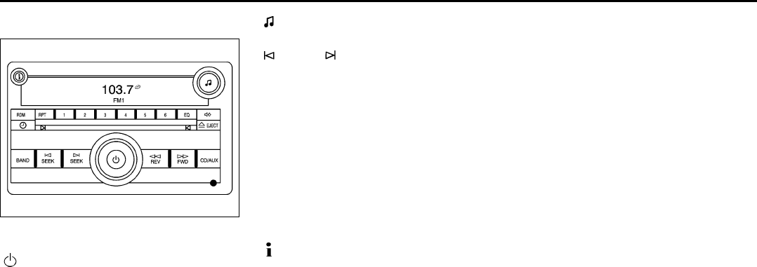
3-41
INSTRUMENT PANEL
78J00-03E
Radio with CD (Base)
1546915
Playing the Radio
(Power/Volume):
Press this knob to turn the system on and
off.
Turn this knob clockwise or counterclock-
wise to increase or decrease the volume.
The radio remembers the previous volume
setting whenever the radio is turned on.
You can still manually adjust the volume by
using the volume knob.
Finding a Station
BAND:
Press this button to switch between FM1,
FM2 or AM. The display shows the selec-
tion.
(Tune):
Turn this knob to select radio stations.
SEEK :
Press the right or left SEEK arrow to go to
the next or to the previous station and stay
there.
To scan stations, press and hold either
SEEK arrow for a few seconds until a beep
sounds. The radio goes to a station, plays
for a few seconds, then goes to the next
station. Press either SEEK arrow again to
stop scanning.
The radio only seeks and scans stations
with a strong signal that are in the selected
band.
(Information):
Press this button to switch the display
between the radio station frequency and
the time. When the ignition is off, press this
button to display the time.
Setting Preset Stations
Up to 18 stations (six FM1, six FM2, and
six AM), can be programmed on the six
numbered pushbuttons, by performing the
following steps:
1) Turn the radio on.
2) Press BAND to select FM1, FM2, or
AM.
3) Tune in the desired station.
4) Press and hold one of the six numbered
pushbuttons for three seconds until a
beep sounds. Whenever that pushbut-
ton is pressed and released, the station
that was set, returns.
5) Repeat the Steps 2 through 4 for each
pushbutton.
Setting the Tone (Bass/Treble)
EQ (Equalization):
To adjust the bass or treble, press the tune
knob or EQ button until the desired tone
control label appears on the display. Turn
the tune knob clockwise or counterclock-
wise to increase or decrease the setting.
You can also adjust the setting by pressing
either the SEEK, FWD (forward), or REV
(reverse) buttons. The display shows the
current bass or treble level. If a station’s
frequency is weak, or if there is static,
decrease the treble.
3-42
INSTRUMENT PANEL
78J00-03E
Adjusting the Speakers (Balance/Fade)
BAL/FADE (Balance/Fade):
To adjust the balance or fade, press this
button or the tune knob until the desired
speaker control label appears on the dis-
play. Turn the tune knob clockwise or coun-
terclockwise to adjust the setting. You can
also adjust the setting by pressing either
the SEEK, FWD, or REV buttons.
Radio Messages
Calibration Error:
The audio system has been calibrated for
your vehicle from the factory. If Calibration
Error appears on the display, it means that
the radio has not been configured properly
for your vehicle and it must be returned to
your dealer for service.
Loc (Locked):
This message is displayed when the
THEFTLOCK® system has locked up the
radio. Take the vehicle to your dealer for
service.
If any error occurs repeatedly or if an error
cannot be corrected, contact your dealer.
Playing a CD
Insert a CD partway into the slot, label side
up. The player pulls it in and the CD should
begin playing.
If the ignition or radio is turned off with a
CD in the player, it stays in the player.
When the ignition or radio is turned on, the
CD starts playing where it stopped, if it was
the last selected audio source.
When a CD is inserted, the CD symbol
appears on the radio display. As each new
track starts to play, the track number
appears on the display.
The CD player can play the smaller 3 inch
(8 cm) single CDs with an adapter ring.
Full-size CDs and the smaller CDs are
loaded in the same manner.
If playing a CD-R, the sound quality may
be reduced due to CD-R quality, the
method of recording, the quality of the
music that has been recorded, and the way
the CD-R has been handled. There may be
an increase in skipping, difficulty in finding
tracks, and/or difficulty in loading and
ejecting. If these problems occur, check
the bottom surface of the CD. If the surface
of the CD is damaged, such as cracked,
broken, or scratched, the CD will not play
properly. If the surface of the CD is soiled,
refer to “Care of Your CDs and DVDs” in
this section for more information.
If there is no apparent damage, try a
known good CD.
Do not add any label to a CD. It could get
caught in the CD player. If a CD is
recorded on a personal computer and a
description label is needed, try labeling the
top of the recorded CD with a marking pen.
If an error appears on the display, see “CD
Messages” later in this section.
EJECT:
Press the CD eject button to eject the CD.
If the CD is not removed, after several sec-
onds, the CD automatically pulls back into
the player.
(Tune):
Turn this knob to select tracks on the CD
currently playing.
SEEK :
Press the left SEEK arrow to go to the start
of the current track, if more than ten sec-
onds have played. Press the right SEEK
arrow to go to the next track. If either SEEK
CAUTION
If a label is added to a CD, or more
than one CD is inserted into the slot
at a time, or an attempt is made to
play scratched or damaged CDs, the
CD player could be damaged. While
using the CD player, use only CDs in
good condition without any label,
load one CD at a time, and keep the
CD player and the loading slot free of
foreign materials, liquids, and debris.

3-43
INSTRUMENT PANEL
78J00-03E
arrow is held or pressed multiple times, the
player continues moving backward or for-
ward through the CD.
REV (Reverse):
Press and hold this button to reverse play-
back quickly within a track. You will hear
sound at a reduced volume. Release this
pushbutton to resume playing the track.
The elapsed time of the track appears on
the display.
FWD (Fast Forward):
Press and hold this pushbutton to advance
playback quickly within a track. You will
hear sound at a reduced volume. Release
this pushbutton to resume playing the
track. The elapsed time of the track
appears on the display.
RDM (Random):
With random, you can listen to CD tracks in
random, rather than sequential order. To
use random, do the following:
1) Press this button to play tracks from the
CD you are listening to in random order.
The random icon appears on the dis-
play.
2) Press this button again to turn off ran-
dom play. The random icon disappears
from the display.
RPT (Repeat):
With repeat, one track can be repeated
(played over and over). To use repeat,
press and release the RPT button. An
arrow symbol appears on the display.
Press RPT again to turn off repeat play.
When repeat is off, the arrow symbol is no
longer displayed.
(Information):
Press this button to switch the display
between the track number, elapsed time of
the track, and the time. When the ignition is
off, press this button to display the time.
BAND:
Press this button to listen to the radio when
a CD is playing. The CD remains safely
inside the radio for future listening.
CD/AUX (CD/Auxiliary):
Press this button to play a CD when listen-
ing to the radio. The CD icon and track
number appears on the display when a CD
is in the player. Press this button again and
the system automatically searches for an
auxiliary input device such as a portable
audio player.
CD Messages
CHECK DISC:
If this message appears on the display
and/or the CD comes out, it could be for
one of the following reasons:
• It is very hot. When the temperature
returns to normal, the CD should play.
• You are driving on a very rough road.
When the road becomes smoother, the
CD should play.
• The CD is dirty, scratched, wet, or
upside down.
• The air is very humid. If so, wait about an
hour and try again.
• There may have been a problem while
burning the CD-R.
• The label may be caught in the CD
player.
If the CD is not playing correctly, for any
other reason, try a known good CD.
If any error occurs repeatedly or if an error
cannot be corrected, contact your dealer. If
the radio displays an error message, write
it down and provide it to your dealer when
reporting the problem.
Using the Auxiliary Input Jack
Your radio system has an auxiliary input
jack located on the lower right side of the
faceplate. This is not an audio output; do
not plug the headphone set into the front
auxiliary input jack. You can however, con-
nect an external audio device such as an
iPod, laptop computer, MP3 player, CD
changer, or cassette tape player, etc. to the
auxiliary input jack for use as another
source for audio listening.
Drivers are encouraged to set up any auxil-
iary device while the vehicle is in park (P).
Refer to “Defensive Driving” in “Your Driv-
ing, the Road, and Your Vehicle” in the
“Driving Your Vehicle” for more information
on driver distraction.
To use a portable audio player, connect a
3.5 mm (1/8 inch) cable to the radio’s front
auxiliary input jack. When a device is con-
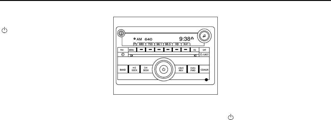
3-44
INSTRUMENT PANEL
78J00-03E
nected, press the radio CD/AUX button to
begin playing audio from the device over
the vehicle speakers.
(Power/Volume):
Turn this knob clockwise or counterclock-
wise to increase or decrease the volume of
the portable player. You may need to do
additional volume adjustments from the
portable device if the volume does not go
loud or soft enough.
BAND:
Press this button to listen to the radio when
a portable audio device is playing. The por-
table audio device continues playing, so
you may want to stop it or turn it off.
CD/AUX (CD/Auxiliary):
Press this button to play a CD when a por-
table audio device is playing.
Press this button again and the system
begins playing audio from the connected
portable audio player. If a portable audio
player is not connected, “No Aux” displays.
Radio with CD (MP3)
1546891
Radio Data System (RDS)
The audio system has a Radio Data Sys-
tem (RDS). The RDS feature is available
for use only on FM stations that broadcast
RDS information. This system relies upon
receiving specific information from these
stations and only works when the informa-
tion is available. While the radio is tuned to
an FM-RDS station, the station name or
call letters appear on the display. In rare
cases, a radio station may broadcast incor-
rect information that causes the radio fea-
tures to work improperly. If this happens,
contact the radio station.
XMTM Satellite Radio Service
XMTM is a satellite radio service that is
based in the 48 contiguous United States
and Canada. XMTM offers a large variety of
coast-to-coast channels including music,
news, sports, talk, traffic/weather (U.S.
subscribers), and children’s programming.
XMTM provides digital quality audio and
text information that includes song title and
artist name. A service fee is required in
order to receive the XMTM service. For
more information, contact XMTM; In the
U.S. at www.xmradio.com or call 1-800-
852-XMXM (9696) or in Canada at
www.xmradio.ca or call 1-877-GET-XMSR
(438-9677).
Playing the Radio
(Power/Volume):
Press this knob to turn the system on and
off.
Turn this knob clockwise or counterclock-
wise to increase or decrease the volume.
Speed Compensated Volume (SCV):
The radio is also equipped with Speed
Compensated Volume (SCV). When SCV
is on, the radio volume automatically
adjusts to compensate for road and wind
noise as you speed up or slow down while
driving. That way, the volume level should
sound about the same as you drive. To
activate SCV:
1) Set the radio volume to the desired
level.

3-45
INSTRUMENT PANEL
78J00-03E
2) Press the MENU button to display the
radio setup menu.
3) Press the pushbutton under the AUTO
VOLUM label on the radio display.
4) Press the pushbutton under the desired
Speed Compensated Volume setting
(OFF, Low, Med, or High) to select the
level of radio volume compensation.
The display times out after approxi-
mately 10 seconds. Each higher setting
allows for more radio volume compen-
sation at faster vehicle speeds.
Finding a Station
BAND:
Press this button to switch between AM,
FM, or XMTM (if equipped). The display
shows the selection.
(Tune):
Turn this knob to select radio stations.
SEEK :
Press the right or left SEEK arrow to go to
the next or to the previous station and stay
there.
To scan stations, press and hold either
SEEK arrow for a few seconds until a beep
sounds. The radio goes to a station, plays
for a few seconds, then goes to the next
station. Press either SEEK arrow again to
stop scanning.
The radio only seeks and scans stations
with a strong signal that are in the selected
band.
(Information) (XMTM Satellite Radio
Service, MP3, and RDS Features):
Press the information button to display
additional text information related to the
current FM-RDS or XMTM station, or MP3
song. A choice of additional information
such as: Channel, Song, Artist, and CAT
may appear. Continue pressing the infor-
mation button to highlight the desired label,
or press the pushbutton positioned under
any one of the labels and the information
about that label is displayed.
When information is not available, No Info
displays.
Storing a Radio Station as a Favorite
Drivers are encouraged to set up their
radio station favorites while the vehicle is
parked. Tune to your favorite stations using
the presets, favorites button, and steering
wheel controls (if equipped). Refer to
“Defensive Driving” in “Your Driving, the
Road, and Your Vehicle” in the “Driving
Your Vehicle” section.
FAV (Favorites):
A maximum of 36 stations can be pro-
grammed as favorites using the six push-
buttons positioned below the radio station
frequency labels and by using the radio
favorites page button (FAV button). Press
the FAV button to go through up to six
pages of favorites, each having six favorite
stations available per page. Each page of
favorites can contain any combination of
AM, FM, or XMTM (if equipped) stations. To
store a station as a favorite, perform the
following steps:
1) Tune to the desired radio station.
2) Press the FAV button to display the
page where you want the station
stored.
3) Press and hold one of the six pushbut-
tons until a beep sounds. Whenever
that pushbutton is pressed and
released, the station that was set,
returns.
4) Repeat the steps for each pushbutton
radio station you want stored as a favor-
ite.
The number of favorites pages can be
setup using the MENU button. To setup the
number of favorites pages, perform the fol-
lowing steps:
1) Press the MENU button to display the
radio setup menu.
2) Press the pushbutton located below the
FAV 1-6 label.
3) Select the desired number of favorites
pages by pressing the pushbutton
located below the displayed page num-
bers.
4) Press the FAV button, or let the menu
time out, to return to the original main
radio screen showing the radio station
frequency labels and to begin the pro-
cess of programming your favorites for
the chosen amount of numbered
pages.

3-46
INSTRUMENT PANEL
78J00-03E
Setting the Tone
(Bass/Midrange/Treble)
BASS/MID/TREB
(Bass, Midrange, or Treble):
To adjust bass, midrange, or treble, press
the tune knob until the tone control labels
appear on the display. Continue pressing
to highlight the desired label, or press the
pushbutton positioned under the desired
label. Turn the tune knob clockwise or
counterclockwise to adjust the highlighted
setting. You can also adjust the highlighted
setting by pressing either the SEEK, FWD
(forward), or REV (reverse) button until the
desired levels are obtained. If a station’s
frequency is weak, or if there is static,
decrease the treble.
To quickly adjust bass, midrange, or treble
to the middle position, press the pushbut-
ton positioned under the BASS, MID, or
TREB label for more than two seconds. A
beep sounds and the level adjusts to the
middle position.
To quickly adjust all tone and speaker con-
trols to the middle position, press the tune
knob for more than two seconds until a
beep sounds.
EQ (Equalization):
Press this button to select preset equaliza-
tion settings.
To return to the manual mode, press the
EQ button until Manual displays or start to
manually adjust the bass, midrange, or tre-
ble by pressing the tune knob.
Adjusting the Speakers (Balance/Fade)
BAL/FADE (Balance/Fade):
To adjust balance or fade, press the tune
knob until the speaker control labels
appear on the display. Continue pressing
to highlight the desired label, or press the
pushbutton positioned under the desired
label. Turn the tune knob clockwise or
counterclockwise to adjust the highlighted
setting. You can also adjust the highlighted
setting by pressing either the SEEK, FWD,
or REV button until the desired levels are
obtained.
To quickly adjust balance or fade to the
middle position, press the pushbutton posi-
tioned under the BAL or FADE label for
more than two seconds. You will hear a
beep and the level will be adjusted to the
middle position.
To quickly adjust all speaker and tone con-
trols to the middle position, press the tune
knob for more than two seconds until a
beep sounds.
Finding a Category (CAT) Station
CAT (Category):
The CAT button is used to find XMTM sta-
tions when the radio is in the XMTM mode.
To find XMTM channels within a desired
category, perform the following:
1) Press the BAND button until the XMTM
frequency is displayed. Press the CAT
button to display the category labels on
the radio display. Continue pressing the
CAT button until the desired category
name is displayed.
2) Press either of the two buttons below
the desired category label to immedi-
ately tune to the first XMTM station
associated with that category.
3) Turn the tune knob, press the buttons
below the right or left arrows displayed,
or press the right or left SEEK buttons
to go to the next or previous XMTM sta-
tion within the selected category.
4) To exit the category search mode,
press the FAV button or BAND button to
display your favorites again.
Undesired XMTM categories can be
removed through the setup menu. To
remove an undesired category, perform the
following:
1) Press the MENU button to display the
radio setup menu.
2) Press the pushbutton located below the
XM CAT label.
3) Turn the tune knob to display the cate-
gory you want removed.
4) Press the pushbutton located under the
Remove label until the category name
along with the word Removed displays.
5) Repeat the steps to remove more cate-
gories.

3-47
INSTRUMENT PANEL
78J00-03E
Removed categories can be restored by
pressing the pushbutton under the Add
label when a removed category is dis-
played or by pressing the pushbutton
under the Restore All label.
The radio does not allow you to remove or
add categories while the vehicle is moving
faster than 5 mph (8 km/h).
Radio Messages
Calibration Error:
The audio system has been calibrated for
your vehicle from the factory. If Calibration
Error displays, it means that the radio has
not been configured properly for your vehi-
cle and it must be returned to your dealer
for service.
Locked:
This message is displayed when the
THEFTLOCK® system has locked up the
radio. Take the vehicle to your dealer for
service.
If any error occurs repeatedly or if an error
cannot be corrected, contact your dealer.
Radio Messages for XM Only
Refer to “XM Radio Messages” in this sec-
tion later in this section for further detail.
Playing a CD
Insert a CD partway into the slot, label side
up. The player pulls it in and the CD should
begin playing.
If the ignition or radio is turned off, with a
CD in the player, it stays in the player.
When the ignition or radio is turned on, the
CD starts playing where it stopped, if it was
the last selected audio source.
When a CD is inserted, the CD symbol
appears on the CD. As each new track
starts to play, the track number appears on
the display.
The CD player can play the smaller 3 inch
(8 cm) single CDs with an adapter ring.
Full-size CDs and the smaller CDs are
loaded in the same manner.
If playing a CD-R, the sound quality may
be reduced due to CD-R quality, the
method of recording, the quality of the
music that has been recorded, and the way
the CD-R has been handled. There may be
an increase in skipping, difficulty in finding
tracks, and/or difficulty in loading and
ejecting. If these problems occur, check
the bottom surface of the CD. If the surface
of the CD is damaged, such as cracked,
broken, or scratched, the CD will not play
properly. If the surface of the CD is soiled,
refer to “Care of Your CDs and DVDs” in
this section for more information.
If there is no apparent damage, try a
known good CD.
Do not add any label to a CD. It could get
caught in the CD player. If a CD is
recorded on a personal computer and a
description label is needed, try labeling the
top of the recorded CD with a marking pen.
If an error appears on the display, see “CD
Messages” later in this section.
EJECT:
Press the CD eject button to eject CD(s).
To eject the CD that is currently playing,
press and release this button. A beep
sounds and Ejecting Disc displays. Once
the disc is ejected, Remove Disc displays.
The CD can be removed. If the CD is not
removed, after several seconds, the CD
automatically pulls back into the player and
begins playing.
(Tune):
Turn this knob to select tracks on the CD
currently playing.
CAUTION
If a label is added to a CD, or more
than one CD is inserted into the slot
at a time, or an attempt is made to
play scratched or damaged CDs, the
CD player could be damaged. While
using the CD player, use only CDs in
good condition without any label,
load one CD at a time, and keep the
CD player and the loading slot free of
foreign materials, liquids, and debris.

3-48
INSTRUMENT PANEL
78J00-03E
SEEK :
Press the left SEEK arrow to go to the start
of the current track, if more than ten sec-
onds have played. Press the right SEEK
arrow to go to the next track. If either SEEK
arrow is held, or pressed multiple times,
the player continues moving backward or
forward through the tracks on the CD.
REV (Reverse):
Press and hold this button to reverse play-
back quickly within a track. You will hear
sound at a reduced volume. Release this
pushbutton to resume playing the track.
The elapsed time of the track appears on
the display.
FWD (Fast Forward):
Press and hold this button to advance play-
back quickly within a track. You will hear
sound at a reduced volume. Release this
button to resume playing the track. The
elapsed time of the track appears on the
display.
RDM (Random):
With random, you can listen to the tracks in
random, rather than sequential order. To
use random, press the CD/AUX button,
insert a disc partway into the slot of the CD
player. A RDM label appears on display.
Press the pushbutton positioned under the
RDM label until Random Current Disc dis-
plays. Press the pushbutton again to turn
off random play.
BAND:
Press this button to listen to the radio when
a CD is playing. The CD remains safely
inside the radio for future listening.
CD/AUX (CD/Auxiliary):
Press this button to play a CD when listen-
ing to the radio. The CD icon and a mes-
sage showing disc and/or track number
appears on the display when a CD is in the
player. Press this button again and the sys-
tem automatically searches for an auxiliary
input device, such as a portable audio
player. If a portable audio player is not con-
nected, “No Input Device Found” displays.
Playing an MP3/WMA CD-R or CD-RW
Disc
If you have a radio with a CD (MP3), it has
the capability of playing an MP3/WMA CD-
R or CD-RW disc. For more information on
how to play an MP3/WMA CD-R or CD-RW
disc, refer to “Using an MP3” in the index.
CD Messages
CHECK DISC:
If this message appears on the display
and/or the CD comes out, it could be for
one of the following reasons:
• It is very hot. When the temperature
returns to normal, the CD should play.
• You are driving on a very rough road.
When the road becomes smoother, the
CD should play.
• The CD is dirty, scratched, wet, or
upside down.
• The air is very humid. If so, wait about an
hour and try again.
• There may have been a problem while
burning the CD.
• The label may be caught in the CD
player.
If the CD is not playing correctly, for any
other reason, try a known good CD.
If any error occurs repeatedly or if an error
cannot be corrected, contact your dealer. If
the radio displays an error message, write
it down and provide it to your dealer when
reporting the problem.
Using the Auxiliary Input Jack
Your radio system has an auxiliary input
jack located on the lower right side of the
faceplate. This is not an audio output; do
not plug the headphone set into the front
auxiliary input jack. You can however, con-
nect an external audio device such as an
iPod, laptop computer, MP3 player, CD
changer, or cassette tape player, etc. to the
auxiliary input jack for use as another
source for audio listening.
Drivers are encouraged to set up any auxil-
iary device while the vehicle is in park (P).
Refer to “Defensive Driving” in “Your Driv-
ing, the Road, and Your Vehicle” in the
“Driving Your Vehicle” section for more
information on driver distraction.

3-49
INSTRUMENT PANEL
78J00-03E
To use a portable audio player, connect a
3.5 mm (1/8 inch) cable to the radio’s front
auxiliary input jack. When a device is con-
nected, press the radio CD/AUX button to
begin playing audio from the device over
the vehicle speakers.
(Power/Volume):
Turn this knob clockwise or counterclock-
wise to increase or decrease the volume of
the portable player. You may need to do
additional volume adjustments from the
portable device if the volume does not go
loud or soft enough.
BAND:
Press this button to listen to the radio when
a portable audio device is playing. The por-
table audio device continues playing, so
you may want to stop it or power it off.
CD/AUX (CD/Auxiliary):
Press this button to play a CD when a por-
table audio device is playing. Press this
button again and the system begins play-
ing audio from the connected portable
audio player. If a portable audio player is
not connected, “No Input Device Found”
displays.
Radio with CD and DVD (MP3)
1631251
If your vehicle has a Rear Seat Entertain-
ment (RSE) system, it has a CD/DVD
radio. Refer to “Rear Seat Entertainment
System” in this section for more informa-
tion on the vehicle’s RSE system.
The DVD player is the top slot on the radio
faceplate. The player is capable of reading
the DTS programmed DVD Audio or DVD
Video media, (DTS and DTS 2.0 are trade-
marks of Digital Theater Systems Inc.).
Dolby® is manufactured under license from
Dolby® Laboratories. Dolby® and the dou-
ble-D symbol are trademarks of Dolby®
Laboratories.
Radio Data System (RDS)
The audio system has a Radio Data Sys-
tem (RDS). The RDS feature is available
for use only on FM stations that broadcast
RDS information. This system relies upon
receiving specific information from these
stations and only works when the informa-
tion is available. While the radio is tuned to
an FM-RDS station, the station name or
call letters display. In rare cases, a radio
station could broadcast incorrect informa-
tion that causes the radio features to work
improperly. If this happens, contact the
radio station.
XMTM Satellite Radio Service
XMTM is a satellite radio service that is
based in the 48 contiguous United States
and Canada. XMTM offers a large variety of
coast-to-coast channels including music,
news, sports, talk, traffic/weather (U.S.
subscribers), and children’s programming.
XMTM provides digital quality audio and
text information that includes song title and
artist name. A service fee is required in
order to receive the XMTM service. For
more information, contact XMTM; In the
U.S. at www.xmradio.com or call 1-800-
852-XMXM (9696) or in Canada at
www.xmradio.ca or call 1-877-GET-XMSR
(438-9677).

3-50
INSTRUMENT PANEL
78J00-03E
Playing the Radio
(Power/Volume):
Press this knob to turn the system on and
off.
Turn this knob clockwise or counterclock-
wise to increase or decrease the volume.
Speed Compensated Volume (SCV):
The radio has Speed Compensated Vol-
ume (SCV). While SCV is on, the radio vol-
ume automatically adjusts to compensate
for road and wind noise as driving speed
changes. That way, the volume level
should sound about the same as you drive.
To activate SCV:
1) Set the radio volume to the desired
level.
2) Press the MENU button to display the
radio setup menu.
3) Press the pushbutton under the AUTO
VOLUM (volume) label on the radio dis-
play.
4) Press the pushbutton under the desired
SCV setting (OFF, Low, Med (medium),
or High) to select the level of radio vol-
ume compensation. The display times
out after approximately 10 seconds.
Each higher setting allows for more
radio volume compensation at faster
vehicle speeds.
Finding a Station
BAND:
Press this button to switch between AM,
FM, or XMTM (if equipped). The display
shows the selection.
(Tune):
Turn this knob to select radio stations.
SEEK :
Press the left or right SEEK arrow to go to
the next or to the previous station and stay
there.
To scan stations, press and hold either
SEEK arrow for a few seconds until a beep
sounds. The radio goes to a station, plays
for a few seconds, then goes to the next
station. Press either SEEK arrow again to
stop scanning.
The radio seeks and scans stations only
with a strong signal that are in the selected
band.
(Information) (XMTM Satellite Radio
Service, MP3, and RDS Features):
Press the information button to display
additional text information related to the
current FM-RDS or XMTM station, or MP3
song. A choice of additional information
such as: Channel, Song, Artist, and CAT
(category) could appear. Continue press-
ing the information button to highlight the
desired label, or press the pushbutton
positioned under any one of the labels and
the information about that label is dis-
played.
When information is not available, No Info
displays.
Storing a Radio Station as a Favorite
Drivers are encouraged to set up their
radio station favorites while the vehicle is
parked. Tune to your favorite stations using
the presets, favorites button, and steering
wheel controls, if the vehicle has them.
Refer to “Defensive Driving” in “Your Driv-
ing, the Road, and Your Vehicle” in the
“Driving Your Vehicle” section.
FAV (Favorites):
A maximum of 36 stations can be pro-
grammed as favorites using the six push-
buttons positioned below the radio station
frequency labels and by using the radio
favorites page button (FAV button). Press
the FAV button to go through up to six
pages of favorites, each having six favorite
stations available per page. Each page of
favorites can contain any combination of
AM, FM, or XMTM (if equipped) stations. To
store a station as a favorite, perform the
following steps:
1) Tune to the desired radio station.
2) Press the FAV button to display the
page where you want the station
stored.
3) Press and hold one of the six pushbut-
tons until a beep sounds. Whenever
that pushbutton is pressed and
released, the station that was set,
returns.

3-51
INSTRUMENT PANEL
78J00-03E
4) Repeat the steps for each pushbutton
radio station you want stored as a favor-
ite.
The number of favorites pages can be
setup using the MENU button. To setup the
number of favorites pages, perform the fol-
lowing steps:
1) Press the MENU button to display the
radio setup menu.
2) Press the pushbutton located below the
FAV 1-6 label.
3) Select the desired number of favorites
pages by pressing the pushbutton
located below the displayed page num-
bers.
4) Press the FAV button, or let the menu
time out, to return to the original main
radio screen showing the radio station
frequency labels and to begin the pro-
cess of programming your favorites for
the chosen amount of numbered
pages.
Setting the Tone
(Bass/Midrange/Treble)
BASS/MID/TREB
(Bass, Midrange, or Treble):
To adjust bass, midrange, or treble, press
the tune knob until the tone control labels
display. Continue pressing to highlight the
desired label, or press the pushbutton
positioned under the desired label. Turn
the tune knob clockwise or counterclock-
wise to adjust the highlighted setting. If a
station’s frequency is weak or if there is
static, decrease the treble.
To quickly adjust bass, midrange, or treble
to the middle position, press the pushbut-
ton positioned under the BASS, MID, or
TREB label for more than two seconds. A
beep sounds and the level adjusts to the
middle position.
To quickly adjust all tone and speaker con-
trols to the middle position, press the tune
knob for more than two seconds until a
beep sounds.
EQ (Equalization):
Press this button to choose bass and tre-
ble equalization settings designed for dif-
ferent types of music. The choices are pop,
rock, country, talk, jazz, and classical.
Selecting MANUAL or changing bass or
treble, returns the EQ to the manual bass
and treble settings.
Unique EQ settings can be saved for each
source.
If the radio has a Bose® audio system, the
EQ settings are either MANUAL or TALK.
Adjusting the Speakers (Balance/Fade)
BAL/FADE (Balance/Fade):
To adjust balance or fade, press the tune
knob until the speaker control labels dis-
play. Press the pushbutton positioned
under the desired label. Turn the tune knob
clockwise or counterclockwise to adjust the
highlighted setting. The highlighted setting
can also be adjusted by pressing either the
SEEK, FWD (forward), or REV (reverse)
button until the desired levels are obtained.
To quickly adjust balance or fade to the
middle position, press the pushbutton posi-
tioned under the BAL or FADE label for
more than two seconds. A beep sounds
and the level adjusts to the middle position.
To quickly adjust both the balance and
fade to the middle position at one time,
press the tune knob for more than two sec-
onds until a beep sounds.

3-52
INSTRUMENT PANEL
78J00-03E
Finding a Category (CAT) Station
CAT (Category):
The CAT button is used to find XMTM sta-
tions when the radio is in the XMTM mode.
To find XMTM channels within a desired
category, perform the following:
1) Press the BAND button until the XM™
frequency displays. Press the CAT but-
ton to display the category labels on the
radio display. Continue pressing the
CAT button until the desired category
name is displayed. Another way to navi-
gate the category list is to press the
REV button or the FWD button.
2) Press either of the two buttons below
the desired category label to immedi-
ately tune to the first XMTM station
associated with that category.
3) Turn the tune knob, press the buttons
below the right or left arrows displayed,
or press the right or left SEEK buttons
to go to the next or previous XMTM sta-
tion within the selected category.
4) To exit the category search mode,
press the FAV button or BAND button to
display your favorites again.
Undesired XMTM categories can be
removed through the setup menu. To
remove an undesired category, perform the
following:
1) Press the MENU button to display the
radio setup menu.
2) Press the pushbutton located below the
XM CAT label.
3) Turn the tune knob to display the cate-
gory you want removed.
4) Press the pushbutton located under the
Remove label until the category name
along with the word Removed displays.
5) Repeat the steps to remove more cate-
gories.
Removed categories can be restored by
pressing the pushbutton under the Add
label when a removed category displays or
by pressing the pushbutton under the
Restore All label.
Categories cannot be removed or added
while the vehicle is moving faster than 5
mph (8 km/h).
Radio Messages
Calibration Error:
The audio system has been calibrated for
your vehicle from the factory. If Calibration
Error displays, it means that the radio has
not been configured properly for your vehi-
cle and it must be returned to your dealer
for service.
Locked:
This message displays when the THEFT-
LOCK® system has locked up the radio.
Take the vehicle to your dealer for service.
If any error occurs repeatedly or if an error
cannot be corrected, contact your dealer.
Radio Messages for XMTM Only
Refer to “XM Radio Messages” in this sec-
tion later in this section for further detail.
Playing a CD
(in either the DVD or CD slot)
Insert a CD partway into the slot, label side
up. The player pulls it in and the CD should
begin playing (loading a disc into the sys-
tem, depending on media type and format
ranges from 5 to 20 seconds for a CD, and
up to 30 seconds for a DVD to begin play-
ing).
If the ignition or radio is turned off, with a
CD in the player, it stays in the player.
When the ignition or radio is turned on, the
CD starts playing where it stopped, if it was
the last selected audio source. The CD is
controlled by the buttons on the radio face-
plate. The DVD/CD decks, (upper slot is
the DVD deck and the lower slot is the CD
deck) of the radio are compatible with most
audio CDs, CD-R, CD-RW, and MP3s.
When a CD is inserted, the text label DVD
or CD symbol appears on the left side of
the radio display. As each new track starts
to play, the track number appears on the
display.
The CD player can play the smaller 3 inch
(8 cm) single CDs with an adapter ring.
Full-size CDs and the smaller CDs are
loaded in the same manner.
If playing a CD-R, the sound quality can be
reduced due to CD-R quality, the method

3-53
INSTRUMENT PANEL
78J00-03E
of recording, the quality of the music that
has been recorded, and the way the CD-R
has been handled. There can be an
increase in skipping, difficulty in finding
tracks, and/or difficulty in loading and
ejecting. If these problems occur, check
the bottom surface of the CD. If the surface
of the CD is damaged, such as cracked,
broken, or scratched, the CD will not play
properly. If the surface of the CD is soiled,
refer to “Care of Your CDs and DVDs” in
this section for more information.
If there is no apparent damage, try a
known good CD.
Do not add any label to a CD. It could get
caught in the CD player. If a CD is
recorded on a personal computer and a
description label is needed, try labeling the
top of the recorded CD with a marking pen.
If an error displays, see “CD Messages”
later in this section.
CD (Eject):
Press and release the CD eject button to
eject the CD that is currently playing in the
bottom slot. A beep sounds and Ejecting
Disc displays. Once the disc is ejected,
Remove Disc displays. The CD can be
removed. If the CD is not removed, after
several seconds, the CD automatically
pulls back into the player.
If loading and reading of a CD cannot be
completed, such as unknown format, etc.,
and the disc fails to eject, press and hold
the DVD eject button for more than five
seconds to force the disc to eject.
DVD (Eject):
Press and release the DVD eject button to
eject the CD that is currently playing in the
bottom slot. A beep sounds and Ejecting
Disc displays. Once the disc is ejected,
Remove Disc displays. The CD can be
removed. If the CD is not removed, after
several seconds, the CD automatically
pulls back into the player.
If loading and reading of a CD cannot be
completed, such as unknown format, etc.,
and the disc fails to eject, press and hold
the DVD eject button for more than five
seconds to force the disc to eject.
(Tune):
Turn this knob to select tracks on the CD
that is currently playing.
SEEK :
Press the left SEEK arrow to go to the start
of the current track, if more than five sec-
onds on the CD have played. If less than
five seconds on the CD have played, the
previous track plays. Press the right SEEK
arrow to go to the next track. If either SEEK
arrow is held, or pressed multiple times,
the player continues moving backward or
forward through the tracks on the CD.
REV (Reverse):
Press and hold this button to reverse play-
back quickly within a track. Sound is heard
at a reduced volume. Release this push-
button to resume playing the track. The
elapsed time of the track displays.
FWD (Fast Forward):
Press and hold this button to advance play-
back quickly within a track. Sound is heard
at a reduced volume. Release this button
to resume playing the track. The elapsed
time of the track displays.
RDM (Random):
With random, tracks can be listened to in
random, rather than sequential order. To
play the tracks from the CD, press the
DVD/CD AUX button when not sourced to
the CD, or insert a disc partway into the
slot. A RDM label displays. Press the
pushbutton positioned under the RDM
label until Random Current Disc displays.
Press the pushbutton again to turn off ran-
dom play.
CAUTION
If a label is added to a CD, or more
than one CD is inserted into the slot
at a time, or an attempt is made to
play scratched or damaged CDs, the
CD player could be damaged. While
using the CD player, use only CDs in
good condition without any label,
load one CD at a time, and keep the
CD player and the loading slot free of
foreign materials, liquids, and debris.

3-54
INSTRUMENT PANEL
78J00-03E
BAND:
Press this button to listen to the radio when
a CD or DVD is playing. The CD or DVD
remains inside the radio for future listening
or for viewing entertainment.
DVD/CD AUX (Auxiliary):
Press this button to cycle through DVD,
CD, or Auxiliary when listening to the radio.
The DVD/CD text label and a message
showing the track or chapter number dis-
plays when a disc is in either slot. Press
this button again and the system automati-
cally searches for an auxiliary input device,
such as a portable audio player. If a porta-
ble audio player is not connected, “No Aux
Input Device” displays. If a disc is in both
the DVD slot and the CD slot the DVD/CD
AUX button cycles between the two
sources and not indicate “No Aux Input
Device”. If a front auxiliary device is con-
nected, the DVD/CD AUX button cycles
through all available options, such as: DVD
slot, CD slot, Front Auxiliary, and Rear
Auxiliary (if available). Refer to “Using the
Auxiliary Input Jack(s)” later in this section,
or “Audio/Video (A/V) Jacks” under, “Rear
Seat Entertainment System” in this section
for more information.
If a disc is inserted into top DVD slot, the
rear seat operator can turn on the video
screen and use the remote control to navi-
gate the CD (tracks only) through the
remote control.
Audio Output
Only one audio source can be heard
through the speakers at one time. An audio
source is defined as DVD slot, CD slot,
XMTM, FM/AM, Front Auxiliary Jack, or
Rear Auxiliary Jack.
Press the power button to turn the radio
on. The radio can be heard through all of
the vehicle speakers.
Front seat passengers can listen to the
radio (AM, FM, or XM) by pressing the
BAND button or the DVD/CD AUX button
to select CD slot, DVD slot, front or rear
auxiliary input (if available).
If a playback device is plugged into the
radio’s front auxiliary input jack or the rear
auxiliary jack, the front seat passengers
are able to listen to playback from this
source through the vehicle speakers. Refer
to “Using the Auxiliary Input Jack(s)” later
in this section, or “Audio/Video (A/V)
Jacks” under, “Rear Seat Entertainment
System” in this section for more informa-
tion.
Playing an MP3/WMA CD-R or CD-RW
Disc
A radio with CD and DVD has the capabil-
ity of playing an MP3/WMA CD-R or CD-
RW disc. For more information on how to
play an MP3/WMA CD-R or CD-RW disc,
refer to “Using an MP3” in the index.
CD Messages
If these messages displays and/or the CD
comes out, it could be for one of the follow-
ing reasons:
Optical Error:
The disc was inserted upside down.
Disk Read Error:
A disc was inserted with an invalid or
unknown format.
Player Error:
There are disc LOAD or disc EJECT prob-
lems.
• It is very hot. When the temperature
returns to normal, the CD should play.
• You are driving on a very rough road.
When the road becomes smoother, the
CD should play.
• The CD is dirty, scratched, wet, or
upside down.
• The air is very humid. If so, wait about an
hour and try again.
• There could have been a problem while
burning the CD.
• The label could be caught in the CD
player.
If the CD is not playing correctly, for any
other reason, try a known good CD.
If any error occurs repeatedly or if an error
cannot be corrected, contact your dealer. If
the radio displays an error message, write
it down and provide it to your dealer when
reporting the problem.

3-55
INSTRUMENT PANEL
78J00-03E
Using the DVD Player
The DVD player is controlled by the but-
tons on the remote control or by the but-
tons on the radio faceplate. Refer to
“Remote Control”, under “Rear Seat Enter-
tainment System” in this section for more
information.
The DVD player is only compatible with
DVDs of the appropriate region code that
is printed on the jacket of most DVDs.
The DVD slot of the radio is compatible
with most audio CDs, CD-R, CD-RW, DVD-
Video, DVD-Audio, DVD-R/RW, DVD+R/
RW media along with MP3 and WMA for-
mats.
If an error message appears on the video
screen or the radio, refer to “DVD Display
Error Messages” under, “Rear Seat Enter-
tainment System” in this section and “DVD
Radio Error Messages” in this section for
more information.
Playing a DVD
DVD/CD AUX (Auxiliary):
Press this button to cycle through DVD,
CD, or Auxiliary when listening to the radio.
The DVD/CD text label and a message
showing track or chapter number displays
when a disc is in either slot.
Press this button again and the system
automatically searches for an auxiliary
input device, such as a portable audio
player. If a portable audio player is not con-
nected, “No Aux Input Device” displays. If a
disc is in both the DVD slot and the CD slot
the DVD/CD AUX button cycles between
the two sources and not indicate “No Aux
Input Device”. If a front auxiliary device is
connected, the DVD/CD AUX button cycles
through all available options, such as: DVD
slot, CD slot, Front Auxiliary, and Rear
Auxiliary (if available). Refer to “Using the
Auxiliary Input Jack(s)” later in this section,
or “Audio/Video (A/V) Jacks” under, “Rear
Seat Entertainment System” in this section
for more information.
(Power):
Press this knob to turn the radio on or off.
Turn this knob clockwise or counterclock-
wise to increase or decrease the volume.
Press and hold the knob for more than two
seconds to turn off the entire radio and
Rear Seat Entertainment (RSE) system
and to start the parental control feature.
Parental control prevents the rear seat
occupant from operating the remote con-
trol.
A lock symbol appears next to the clock
display. The parental control feature
remains on until this button is pressed and
held for more than two seconds again, or
until the driver turns the ignition off and
exits the vehicle.
(Tune):
Turn this knob to change tracks on a CD or
DVD, to manually tune a radio station, or to
change clock or date settings, while in the
clock or date setting mode. See the infor-
mation given earlier in this section specific
to the radio, CD, and the DVD. Also, refer
to “Setting the Time” in the index, for set-
ting the clock and date.
SEEK (Previous Track/Chapter):
Press this button to return to the start of
the current track or chapter. Press this but-
ton again to go to the previous track or
chapter. This button might not work when
the DVD is playing the copyright informa-
tion or the previews.
SEEK (Next Track/Chapter):
Press this button to go to the next track or
chapter. This button might not work when
the DVD is playing the copyright informa-
tion or the previews.
REV (Reverse):
Press this button to quickly reverse the CD
or DVD at five times the normal speed. The
radio displays the elapsed time while in
fast reverse. To stop fast reversing, press
this button again. This button might not
work when the DVD is playing the copy-
right information or the previews.
FWD (Fast Forward):
Press this button to fast forward the CD or
DVD. The radio displays the elapsed time
and fast forwards five times the normal
speed. To stop fast forwarding, press this
button again. This button might not work
when the DVD is playing the copyright
information or the previews.

3-56
INSTRUMENT PANEL
78J00-03E
(Eject):
Press this button to eject a CD or DVD. If a
CD or DVD is ejected, but not removed, the
player automatically pulls it back in after 15
seconds.
If loading and reading of a CD cannot be
completed, because of an unknown for-
mat, etc., and the disc fails to eject, press
and hold the CD eject button for more than
five seconds to force the disc to eject.
DVD-V (Video) Display Buttons
Once a DVD-V is inserted, the radio dis-
play menu shows several tag options for
DVD playing. Press the pushbuttons
located under any desired tag option dur-
ing DVD playback. See the tag options
listed below for more information.
The rear seat passenger can navigate the
DVD-V menus and controls through the
remote control. Refer to “Remote Control”,
under “Rear Seat Entertainment System”
in this section for more information. The
Video Screen automatically turns on when
the DVD-V is inserted into the DVD slot.
/ (Play/Pause):
Press either the play or pause icon dis-
plays on the radio system, to toggle
between pausing or restarting playback of
a DVD. If the forward arrow is showing on
display, the system is in pause mode. If the
pause icon is showing on display, the sys-
tem is in playback mode. If the DVD screen
is off, press the play button to turn the
screen on.
Some DVDs begin playing after the pre-
views have finished, although there might
be a delay of up to 30 seconds. If the DVD
does not begin playing the movie automati-
cally, press the pushbutton located under
the play/pause symbol tag displayed on
the radio. If the DVD still does not play,
refer to the on-screen instructions, if avail-
able.
(Stop):
Press this button to stop playing, rewind-
ing, or fast forwarding a DVD.
(Enter):
Press this button to select the choices that
are highlighted in any menu.
(Menu):
Press this button to access the DVD menu.
The DVD menu is different on every DVD.
Use the pushbuttons located under the
navigation arrows to navigate the cursor
through the DVD menu. After making a
selection press the enter button. This but-
ton only operates when using a DVD.
Nav (Navigate):
Press this button to display directional
arrows for navigating through the menus.
(Return):
Press this button to exit the current active
menu and return to the previous menu.
This button operates only when a DVD is
playing and a menu is active.
DVD-A (Audio) Display Buttons
Once a DVD-A is inserted, radio display
menu shows several tag options for DVD
playing. Press the pushbuttons located
under any desired tag option during DVD
playback. See the tag options listed below
for more information. The rear seat opera-
tor can navigate the DVD-A menus and
controls through the remote control. Refer
to “Remote Control”, under “Rear Seat
Entertainment System” in this section for
more information. The Video Screen does
not automatically power on when the DVD-
A is inserted into the DVD slot. It must be
manually turned on by the rear seat occu-
pant through the remote control power but-
ton.
/ (Play/Pause):
Press either the play or pause icon dis-
plays on the radio system, to toggle
between pausing or restarting playback of
a DVD. If the forward arrow is showing on
display, the system is in pause mode. If the
pause icon is showing on display, the sys-
tem is in playback mode.
Group :
Press this button to cycle through musical
groupings on the DVD-A disc.
Nav (Navigate):
Press this button to display directional
arrows for navigating through the menus.
(Audio Stream):
Press this button to cycle through audio
stream formats located on the DVD-A disc.

3-57
INSTRUMENT PANEL
78J00-03E
There is not any type of notification for the
customer to see through the radio display,
but VSM has a text field that shows audio
stream changing.
Inserting a Disc
To play a disc, gently insert the disc, with
the label side up, into the loading slot. The
DVD player might not accept some paper
labeled media. The player starts loading
the disc into the system and show “Load-
ing Disc” on the radio display. At the same
time, the radio displays a softkey menu of
option(s). Some discs automatically play
the movie while others default to the soft-
key menu display, which requires the Play,
Enter, or Navigation softkeys to be
pressed; either by softkey or by the rear
seat passenger using the remote control.
Loading a disc into the system, depending
on media type and format, ranges from
5 to 20 seconds for a CD, and up to 30
seconds for a DVD.
Stopping and Resuming Playback
To stop playing a DVD without turning off
the system, press the stop button on the
remote control, or press the pushbutton
located under the stop or the play/pause
symbol tags displayed on the radio. If the
radio head is sourced to something other
than DVD-V, press the DVD/CD AUX but-
ton to make DVD-V the active source. To
resume DVD playback, press the play/
pause button on the remote control, or
press the pushbutton located under the
play/pause symbol tag displayed on the
radio. The DVD should resume play from
where it last stopped if the disc has not
been ejected and the stop button has not
been pressed twice on the remote control.
If the disc has been ejected or the stop but-
ton has been pressed twice on the remote
control, the disc resumes playing at the
beginning of the disc.
Ejecting a Disc
Press the eject button on the radio to eject
the disc. If a disc is ejected from the radio,
but not removed, the radio reloads the disc
after a short period of time. The disc is
stored in the radio. The radio does not
resume play of the disc automatically. In
case loading and reading of a DVD or CD
cannot be completed (unknown format,
etc.), and the disc fails to eject, press and
hold the DVD Eject button more than five
seconds to force the disc to eject.
DVD Radio Error Messages
Player Error:
This message displays when there are disc
load or eject problems.
Disc Format Error:
This message displays, if the disc is
inserted with the disc label wrong side up,
or if the disc is damaged.
Disc Region Error:
This message displays, if the disc is not
from a correct region.
No Disc Inserted:
This message displays, if no disc is
present when the EJECT or DVD/CD AUX
button is pressed on the radio.
Using the Auxiliary Input Jack(s)
The radio system has an auxiliary input
jack located on the lower right side of the
faceplate. This is not an audio output; do
not plug the headphone set into the front
auxiliary input jack. However, an external
audio device such as an iPod, laptop com-
puter, MP3 player, CD player, or cassette
tape player, etc. can be connected to the
auxiliary input jack for use as another
source for audio listening.
Drivers are encouraged to set up any auxil-
iary device while the vehicle is in PARK
(P). Refer to “Defensive Driving” in “Your
Driving, the Road, and Your Vehicle” in the
“Driving Your Vehicle” section for more
information on driver distraction.
To use a portable audio player, connect a
1/8 inch (3.5 mm) cable to the radio’s front
auxiliary input jack. While a device is con-
nected, the radio automatically begins
playing audio from the device over the
vehicle speakers.

3-58
INSTRUMENT PANEL
78J00-03E
To listen to a device through the rear auxil-
iary input over the speakers, cycle the
DVD/CD Aux button on the radio faceplate
until “Rear Aux Input” displays on the radio.
The RSA or DVD Screen must be on in
order for the radio to source to rear auxil-
iary.
(Power/Volume):
Turn this knob clockwise or counterclock-
wise to increase or decrease the volume of
the portable player. Additional volume
adjustments might be needed from the
portable device if the volume is not loud or
soft enough.
BAND:
Press this button to listen to the radio when
a portable audio device is playing. The por-
table audio device continues playing, so
you might want to stop it or power it off.
DVD/CD AUX (CD/Auxiliary):
Press this button to cycle through DVD,
CD, or Auxiliary when listening to the radio.
The DVD/CD text label and a message
showing track or chapter number displays
when a disc is in either slot. Press this but-
ton again and the system automatically
searches for an auxiliary input device, such
as a portable audio player. If a portable
audio player is not connected, “No Aux
Input Device” displays. If a disc is in both
the DVD slot and the CD slot the DVD/CD
AUX button cycles between the two
sources and not indicate “No Aux Input
Device”. If a front auxiliary device is con-
nected, the DVD/CD AUX button cycles
through all available options, such as: DVD
slot, CD slot, Front Auxiliary, and Rear
Auxiliary (if available). Refer to “Using the
Auxiliary Input Jack(s)” later in this section,
or “Audio/Video (A/V) Jacks” under, “Rear
Seat Entertainment System” in this section
for more information.
Using an MP3
(Radio with Single CD Player)
MP3 CD-R or CD-RW Disc
The radio plays MP3 files that were
recorded on a CD-R or CD-RW disc. The
files can be recorded with the following
fixed bit rates: 32 kbps, 40 kbps, 56 kbps,
64 kbps, 80 kbps, 96 kbps, 112 kbps, 128
kbps, 160 kbps, 192 kbps, 224 kbps, 256
kbps, and 320 kbps or a variable bit rate.
Song title, artist name, and album are
available for display by the radio when
recorded using ID3 tags version 1 and 2.
Compressed Audio
The radio will also play discs that contain
both uncompressed CD audio (.CDA files)
and MP3 files. By default the radio shows
the MP3 label on the left side of the screen
but plays both file formats in the order in
which they were recorded to the disc.
MP3 Format
If you burn your own MP3 disc on a per-
sonal computer:
• Make sure the MP3 files are recorded on
a CD-R or CD-RW disc.
• Do not mix standard audio and MP3 files
on one disc.
• The CD player is able to read and play a
maximum of 50 folders, 15 playlists, and
512 folders and files.
• Create a folder structure that makes it
easy to find songs while driving. Orga-
nize songs by albums using one folder
for each album. Each folder or album
should contain 18 songs or less.
• Avoid subfolders. The system can sup-
port up to eight subfolders deep, how-
ever, keep the total number of folders to
a minimum in order to reduce the com-
plexity and confusion in trying to locate a
particular folder during playback.
• Make sure playlists have a .mp3 or .wpl
extension (other file extensions may not
work).
• Minimize the length of the file, folder, or
playlist names. Long file, folder, or playl-
ist names, or a combination of a large
number of files and folders, or playlists
may cause the player to be unable to
play up to the maximum number of files,
folders, playlists, or sessions. If you wish
to play a large number of files, folders,
playlists or sessions, minimize the length
of the file, folder, or playlist name. Long
names also take up more space on the
display, potentially getting cut off.
• Finalize the audio disc before you burn it.
Trying to add music to an existing disc
may cause the disc not to function in the
player.

3-59
INSTRUMENT PANEL
78J00-03E
You can change playlists by using the pre-
vious and next folder buttons, the tuner
knob, or the seek buttons. You can also
play an MP3 CD-R that was recorded
using no file folders. If a CD-R contains
more than the maximum of 50 folders, 15
playlists, and 512 folders and files, the
player lets you access and navigate up to
the maximum, but all items over the maxi-
mum are not accessible.
Root Directory
The root directory of the CD-R is treated
as a folder. If the root directory has com-
pressed audio files, the directory is dis-
played as the CD label. All files contained
directly under the root directory are
accessed prior to any root directory fold-
ers. However, playlists (Px) are always
accessed before root folders or files.
If a disc contains both uncompressed CD
audio (.CDA) and MP3 files, a folder under
the root directory called CD access all of
the CD audio tracks on the disc.
Empty Directory or Folder
If a root directory or a folder exists some-
where in the file structure that contains
only folders/subfolders and no compressed
files directly beneath them, the player
advances to the next folder in the file struc-
ture that contains compressed audio files.
The empty folder does not display.
No Folder
When the CD-R contains only compressed
files, the files are located under the root
folder. The next and previous folder func-
tions do not display on a CD-R that was
recorded without folders or playlists.
When the CD-R contains only playlists and
compressed audio files, but no folders, all
files are located under the root folder. The
folder down and the folder up buttons
searches playlists (Px) first and then goes
to the root folder.
Order of Play
Tracks recorded to the CD-R are played in
the following order:
• Play begins from the first track in the first
playlist and continues sequentially
through all tracks in each playlist. When
the last track of the last playlist has been
played, play continues from the first track
of the first playlist.
• Play begins from the first track in the first
folder and continues sequentially
through all tracks in each folder. When
the last track of the last folder has
played, play continues from the first track
of the first folder.
When play enters a new folder, the display
does not automatically show the new folder
name unless you have chosen the folder
mode as the default display. The new track
name appears on the display.
File System and Naming
The song name that displays is the song
name that is contained in the ID3 tag. If the
song name is not present in the ID3 tag,
then the radio displays the file name with-
out the extension (such as .mp3) as the
track name.
Track names longer than 32 characters or
four pages are shortened. The display
does not show parts of words on the last
page of text and the extension of the file-
name is not displayed.
Preprogrammed Playlists
You can access preprogrammed playlists
that were created using WinAmpTM, Music-
MatchTM, or Real JukeboxTM software,
however, you do not have playlist editing
capability using the radio. These playlists
are treated as special folders containing
compressed audio song files.
Playing an MP3
Insert a CD-R partway into the slot label
side up. The player pulls it in, and the CD-
R should begin playing.
If you turn off the ignition or radio with a
CD-R in the player it stays in the player.
When you turn on the ignition or radio, the
CD-R starts to play where it stopped, if it
was the last selected audio source.
As each new track starts to play, the track
number and song title appears on the dis-
play.
The CD player can play the smaller 3 inch
(8 cm) single CD-Rs with an adapter ring.
Full-size CD-Rs and the smaller CD-Rs
are loaded in the same manner.

3-60
INSTRUMENT PANEL
78J00-03E
If playing a CD-R, the sound quality may
be reduced due to CD-R quality, the
method of recording, the quality of the
music that has been recorded, and the way
the CD-R has been handled. There may be
an increase in skipping, difficulty in finding
tracks, and/or difficulty in loading and
ejecting. If these problems occur, check
the bottom surface of the CD. If the surface
of the CD is damaged, such as cracked,
broken, or scratched, the CD will not play
properly. If the surface of the CD is soiled,
refer to “Care of Your CDs and DVDs” in
this section “Care of Your CDs and DVDs”
for more information.
If there is no apparent damage, try a
known good CD.
Do not add any label to a CD, it could get
caught in the CD player. If a CD is
recorded on a personal computer and a
description label is needed, try labeling the
top of the recorded CD with a soft marker
pen.
If an error appears on the display, see “CD
Messages” later in this section.
EJECT:
Press the CD eject button to eject CD-R(s).
To eject the CD-R that is currently playing,
press and release this button. A beep
sounds and Ejecting Disc displays. Once
the disc is ejected, Remove Disc displays.
The CD-R can be removed. If the CD-R is
not removed, after several seconds, the
CD-R automatically pulls back into the
player and begins playing.
(Tune):
Turn this knob to select MP3 files on the
CD-R currently playing.
SEEK :
Press the left SEEK arrow to go to the start
of the current MP3 file, if more than ten
seconds have played. Press the right
SEEK arrow to go to the next MP3 file. If
either SEEK arrow is held or pressed multi-
ple times, the player continues moving
backward or forward through MP3 files on
the CD.
(Previous Folder):
Press the pushbutton positioned under the
Folder label to go to the first track in the
previous folder.
(Next Folder):
Press the pushbutton positioned under the
Folder label to go to the first track in the
next folder.
REV (Reverse):
Press and hold this button to reverse play-
back quickly within an MP3 file. You will
hear sound at a reduced volume. Release
this button to resume playing the file. The
elapsed time of the file appears on the dis-
play.
FWD (Fast Forward):
Press and hold this button to advance play-
back quickly within an MP3 file. You will
hear sound at a reduced volume. Release
this button to resume playing the file. The
elapsed time of the file appears on the dis-
play.
RDM (Random):
With random, you can listen to MP3 files
on the CD-R in random, rather than
sequential order. To use random, press the
pushbutton positioned under the RDM
label until Random Current Disc displays.
Press the same pushbutton again to turn
off random play.
(Music Navigator):
Use the music navigator feature to play
MP3 files on the CD-R in order by artist or
album. Press the pushbutton located
below the music navigator label. The
player scans the disc to sort the files by
artist and album ID3 tag information. It may
take several minutes to scan the disc
CAUTION
If a label is added to a CD, or more
than one CD is inserted into the slot
at a time, or an attempt is made to
play scratched or damaged CDs, the
CD player could be damaged. While
using the CD player, use only CDs in
good condition without any label,
load one CD at a time, and keep the
CD player and the loading slot free of
foreign materials, liquids, and debris.

3-61
INSTRUMENT PANEL
78J00-03E
depending on the number of MP3 files
recorded to the CD-R. The radio may
begin playing while it is scanning the disc
in the background. When the scan is fin-
ished, the CD-R begins playing again.
Once the disc has been scanned, the
player defaults to playing MP3 files in order
by artist. The current artist playing is
shown on the second line of the display
between the arrows. Once all songs by that
artist are played, the player moves to the
next artist in alphabetical order on the CD-
R and begins playing MP3 files by that art-
ist. If you want to listen to MP3 files by
another artist, press the pushbutton
located below either arrow button. You will
go to the next or previous artist in alpha-
betical order. Continue pressing either but-
ton until the desired artist is displayed.
To change from playback by artist to play-
back by album, press the pushbutton
located below the Sort By label. From the
sort screen, push one of the buttons below
the album button. Press the pushbutton
below the back label to return to the main
music navigator screen. Now the album
name is displayed on the second line
between the arrows and songs from the
current album begins to play. Once all
songs from that album are played, the
player moves to the next album in alpha-
betical order on the CD-R and begin play-
ing MP3 files from that album.
To exit music navigator mode, press the
pushbutton below the Back label to return
to normal MP3 playback.
BAND:
Press this button to listen to the radio when
a CD is playing. The CD remains safely
inside the radio for future listening.
CD/AUX (CD/Auxiliary):
Press this button to play a CD when listen-
ing to the radio. The CD icon and a mes-
sage showing disc and/or track number
appears on the display when a CD is in the
player. Press this button again and the sys-
tem automatically searches for an auxiliary
input device such as a portable audio
player. If a portable audio player is not con-
nected, “No Input Device Found” displays.
Using an MP3
(Radio with CD and DVD Player)
MP3/WMA CD-R or CD-RW Disc Com-
pressed Audio or Mixed Mode Discs
The radio also plays discs that contain
both uncompressed CD audio (.CDA files)
and MP3/WMA files depending on which
slot the disc is loaded into. By default the
radio reads only the uncompressed audio
(.CDA) and ignores the MP3/WMA files on
the DVD deck. On the CD deck, pressing
the CAT button toggles between com-
pressed and uncompressed audio format,
the default being the uncompressed format
(.CDA).
MP3/WMA Format
If you burn your own MP3/WMA disc on a
personal computer:
• Make sure the MP3 files are recorded on
a CD-R or CD-RW disc.
• Do not mix standard audio and MP3 files
on one disc.
• The CD player (lower slot) is able to read
and play a maximum combination of 512
files and folders. The DVD player (upper
slot) is able to read 255 folders, 15 playl-
ists and 40 sessions.
• Create a folder structure that makes it
easy to find songs while driving. Orga-
nize songs by albums using one folder
for each album. Each folder or album
should contain 18 songs or less.
• Avoid subfolders. The system can sup-
port up to eight subfolders deep, how-
ever, keep the total number of folders to
a minimum in order to reduce the com-
plexity and confusion in trying to locate a
particular folder during playback.
• Make sure playlists have a .m3u, .wpl or
.pls extension as other file extensions
may not work.
• Minimize the length of the file, folder or
playlist names. Long file, folder, or playl-
ist names, or a combination of a large
number of files and folders, or playlists
may cause the player to be unable to
play up to the maximum number of files,
folders, playlists, or sessions. If you wish
to play a large number of files, folders,
playlists, or sessions, minimize the

3-62
INSTRUMENT PANEL
78J00-03E
length of the file, folder, or playlist name.
Long names also take up more space on
the display, potentially getting cut off.
• Finalize the audio disc before you burn it.
Trying to add music to an existing disc
may cause the disc not to function in the
player.
Root Directory
The root directory of the CD-R is treated
as a folder. If the root directory has com-
pressed audio files, the directory is dis-
played as F1 ROOT. All files contained
directly under the root directory are
accessed prior to any root directory fold-
ers. However, playlists (Px) are always
accessed before root folders or files.
Empty Directory or Folder
If a root directory or a folder exists some-
where in the file structure that contains
only folders/subfolders and no compressed
files directly beneath them, the player
advances to the next folder in the file struc-
ture that contains compressed audio files.
The empty folder does not display.
No Folder
When the CD-R contains only compressed
files, the files are located under the root
folder. The next and previous folder func-
tion does not function on a CD-R that was
recorded without folders or playlists. When
displaying the name of the folder the radio
displays ROOT.
When the CD-R contains only playlists and
compressed audio files, but no folders, all
files are located under the root folder. The
folder down and the folder up buttons
search playlists (Px) first and then goes to
the root folder. When the radio displays the
name of the folder the radio displays
ROOT.
Order of Play
Tracks recorded to the CD-R are played in
the following order:
• Play begins from the first track in the first
playlist and continues sequentially
through all tracks in each playlist. When
the last track of the last playlist has
played, play continues from the first track
of the first playlist.
• Play begins from the first track in the first
folder and continues sequentially
through all tracks in each folder. When
the last track of the last folder has
played, play continues from the first track
of the first folder.
When play enters a new folder, the display
does not automatically show the new folder
name unless the folder mode was chosen
as the default display. The new track name
displays.
File System and Naming
The song name that is displayed is the
song name that is contained in the ID3 tag.
If the song name is not present in the ID3
tag, then the radio displays the file name
without the extension (such as .mp3) as
the track name.
Track names longer than 32 characters or
four pages are shortened. Parts of words
on the last page of text and the extension
of the filename displays.
Preprogrammed Playlists
Preprogrammed playlists that were created
using WinAmpTM, MusicMatchTM, or Real
JukeboxTM software can be accessed,
however, they cannot be edited using the
radio. These playlists are treated as spe-
cial folders containing compressed audio
song files.
Playing an MP3
(in either the DVD or CD slot)
Insert a CD-R partway into either the top or
bottom slot, label side up. The player pulls
it in, and the CD-R should begin playing.
Depending on the format of the disc, a
softkey menu appears and allows naviga-
tion of the disc. The menu reads left to
right as RDM (Randomize song play
order), a Folder icon with left and right
arrows (to move up or down through avail-
able folders), a PL tag if the disc has a
Playlist available, and a Music Navigator
tag. If a Playlist tag is shown, toggling this
key brings up a Folder softkey only or the
menu as previously described.
If the ignition or radio is turned off with a
CD-R in the player, it stays in the player.
When the ignition or radio is turned on, the
CD-R starts to play where it stopped, if it
was the last selected audio source.

3-63
INSTRUMENT PANEL
78J00-03E
As each new track starts to play, the track
number and song title displays.
The CD player can play the smaller 3 inch
(8 cm) single CD-Rs with an adapter ring.
Full-size CD-Rs and the smaller CD-Rs
are loaded in the same manner.
If playing a CD-R, the sound quality can be
reduced due to CD-R quality, the method
of recording, the quality of the music that
has been recorded, and the way the CD-R
has been handled. There can be an
increase in skipping, difficulty in finding
tracks, and/or difficulty in loading and
ejecting. If these problems occur, check
the bottom surface of the CD. If the surface
of the CD is damaged, such as cracked,
broken, or scratched, the CD will not play
properly. If the surface of the CD is soiled,
refer to “Care of Your CDs and DVDs” in
this section for more information.
If there is no apparent damage, try a
known good CD.
Do not add any label to a CD. It could get
caught in the CD player. If a CD is
recorded on a personal computer and a
description label is needed, try labeling the
top of the recorded CD with a marking pen.
If an error displays, see “CD Messages”
later in this section.
CD (Eject):
Press and release the CD eject button to
eject the CD-R that is currently playing in
the bottom slot. A beep sounds and Eject-
ing Disc displays. Once the disc is ejected,
Remove Disc displays. The CD-R can be
removed. If the CD-R is not removed, after
several seconds, the CD-R automatically
pulls back into the player.
If loading and reading of a CD cannot be
completed, such as unknown format, etc.,
and the disc fails to eject, press and hold
the DVD eject button for more than five
seconds to force the disc to eject.
DVD (Eject):
Press and release the DVD eject button to
eject the CD-R that is currently playing in
the top slot. A beep sounds and Ejecting
Disc displays. Once the disc is ejected,
Remove Disc displays. The CD-R can be
removed. If the CD-R is not removed, after
several seconds, the CD-R automatically
pulls back into the player. If loading and
reading of a CD cannot be completed,
such as unknown format, etc., and the disc
fails to eject, press and hold the DVD eject
button for more than five seconds to force
the disc to eject.
(Tune):
Turn this knob to select MP3 files on the
CD-R that is currently playing.
SEEK :
Press the left SEEK arrow to go to the start
of the current MP3 file, if more than five
seconds have played. If less than five sec-
onds have played, the previous MP3 file
plays. Press the right SEEK arrow to go to
the next MP3 file. If either SEEK arrow is
held, or pressed multiple times, the player
continues moving backward or forward
through the MP3 files on the CD.
(Previous Folder):
Press the pushbutton positioned under the
Folder label to go to the first track in the
previous folder.
(Next Folder):
Press the pushbutton positioned under the
Folder label to go to the first track in the
next folder.
REV (Reverse):
Press and hold this button to reverse play-
back quickly within an MP3 file. Sound is
heard at a reduced volume. Release this
button to resume playing the file. The
elapsed time of the file displays.
FWD (Fast Forward):
Press and hold this button to advance play-
back quickly within an MP3 file. Sound is
heard at a reduced volume. Release this
CAUTION
If a label is added to a CD, or more
than one CD is inserted into the slot
at a time, or an attempt is made to
play scratched or damaged CDs, the
CD player could be damaged. While
using the CD player, use only CDs in
good condition without any label,
load one CD at a time, and keep the
CD player and the loading slot free of
foreign materials, liquids, and debris.

3-64
INSTRUMENT PANEL
78J00-03E
button to resume playing the file. The
elapsed time of the file displays.
RDM (Random):
With the random setting, MP3 files on the
CD-R can be listened to in random, rather
than sequential order. To play MP3 files
from the CD-R you are listening to in ran-
dom order, press the pushbutton posi-
tioned under the RDM label until Random
Current Disc displays. Press the same
pushbutton again to turn off random play.
(Music Navigator):
Use the music navigator feature to play
MP3 files on the CD-R in order by artist or
album. Press the pushbutton located
below the music navigator label. The
player scans the disc to sort the files by
artist and album ID3 tag information. It
might take several minutes to scan the disc
depending on the number of MP3 files
recorded to the CD-R.
To cancel music navigator while the player
is scanning, press the pushbutton located
below the music navigator label or eject
the disc. The radio can begin playing while
it is scanning the disc in the background.
When the scan is finished, the CD-R
begins playing again.
Once the disc has been scanned, the
player defaults to playing MP3 files in order
by artist. The current artist playing is
shown on the second line of the display
between the arrows. If you want to listen to
MP3 files by another artist, press the push-
button located below either arrow button.
The disc goes to the next or previous artist
in alphabetical order. Continue pressing
either button until the desired artist is dis-
played.
To change from playback by artist to play-
back by album, press the pushbutton
located below the Sort By label. From the
sort screen, push one of the buttons below
the album button. Press the pushbutton
below the back label to return to the main
music navigator screen. Now the album
name is displayed on the second line
between the arrows and songs from the
current album begin to play. Once all songs
from that album are played, the player
moves to the next album in alphabetical
order on the CD-R and begins playing MP3
files from that album.
To exit music navigator mode, press the
pushbutton below the Back label to return
to normal MP3 playback.
BAND:
Press this button to listen to the radio when
a CD or a DVD is playing. The CD or DVD
remains inside the radio for future listening
or viewing entertainment.
DVD/CD AUX (Auxiliary):
Press this button to cycle through DVD,
CD, or Auxiliary when listening to the radio.
The DVD/CD text label and a message
showing track or chapter number displays
when a disc is in either slot. Press this but-
ton again and the system automatically
searches for an auxiliary input device,
such as a portable audio player. If a porta-
ble audio player is not connected, “No Aux
Input Device” displays. If a disc is in both
the DVD slot and the CD slot the DVD/CD
AUX button cycles between the two
sources and not indicate connected, the
DVD/CD AUX button cycles through all
available options, such as: DVD slot, CD
slot, Front Auxiliary, and Rear Auxiliary (if
available). Refer to “Using the Auxiliary
Input Jack(s)” later in this section, or
“Audio/Video (A/V) Jacks” under, “Rear
Seat Entertainment System” in this section
for more information.
If a MP3 is inserted into top DVD slot, the
rear seat operator can turn on the video
screen and use the remote control to navi-
gate the CD (tracks only) through the
remote control.

3-65
INSTRUMENT PANEL
78J00-03E
XM Radio Messages
Radio Display Message Condition Action Required
XL
(Explicit Language Channels)
XL on the radio display, after the
channel name, indicates content
with explicit language.
These channels, or any others, can be blocked at a cus-
tomer’s request, by calling 1-800-852-XMXM (9696).
XM Updating Updating encryption code The encryption code in the receiver is being updated, and no
action is required. This process should take no longer than 30
seconds.
No XM Signal Loss of signal The system is functioning correctly, but the vehicle is in a loca-
tion that is blocking the XMTM signal. When you move into an
open area, the signal should return.
Loading XM Acquiring channel audio
(after four second delay)
The audio system is acquiring and processing audio and text
data. No action is needed. This message should disappear
shortly.
Channel Off Air Channel not in service This channel is not currently in service. Tune to another chan-
nel.
Channel Unavail Channel no longer available This previously assigned channel is no longer assigned. Tune
to another station. If this station was one of the presets,
choose another station for that preset button.
No Artist Info Artist Name/Feature not available No artist information is available at this time on this channel.
The system is working properly.
No Title Info Song/Program Title not available No song title information is available at this time on this chan-
nel. The system is working properly.
No CAT Info Category Name not available No category information is available at this time on this chan-
nel. The system is working properly.
No Information No Text/Informational message
available
No text or informational messages are available at this time on
this channel. The system is working properly.

3-66
INSTRUMENT PANEL
78J00-03E
Radio Display Message Condition Action Required
CAT Not Found No channel available for the chosen
category
There are no channels available for the selected category.
The system is working properly.
XM Theft Locked Theft lock active The XMTM receiver in the vehicle could have previously been
in another vehicle. For security purposes, XMTM receivers
cannot be swapped between vehicles. If this message
appears after having your vehicle serviced, check with your
dealer.
XM Radio ID Radio ID label (channel 0) If tuned to channel 0, this message alternates with the XMTM
Radio eight digit radio ID label. This label is needed to acti-
vate the service.
Unknown Radio ID not known
(should only be if hardware failure)
If this message is received when tuned to channel 0, there
could be a receiver fault. Consult with your dealer.
Check XM Receivr Hardware failure If this message does not clear within a short period of time,
the receiver could have a fault. Consult with your dealer.
XM Not Available XMTM Not Available If this message does not clear within a short period of time,
the receiver could have a fault. Consult with your dealer.

3-67
INSTRUMENT PANEL
78J00-03E
Navigation/Radio System
Your vehicle may have a navigation radio
system.
The navigation radio system has built-in
features intended to minimize driver dis-
traction. Technology alone, no matter how
advanced, can never replace your own
judgment. For complete information on
your navigation radio system, including tips
on helping to reduce distractions while
driving, see the Navigation System Man-
ual.
Rear Seat Entertainment System
Your vehicle may have a DVD Rear Seat
Entertainment (RSE) system. The RSE
system works with the vehicle's audio sys-
tem. The DVD player is part of the front
radio. The RSE system includes a radio
with a DVD player, a video display screen,
audio/video jacks, two wireless head-
phones, and a remote control. Refer to
“Radio with CD and DVD (MP3)” in this
section for more information on the vehi-
cle’s audio/DVD system.
Before You Drive
The RSE is designed for rear seat passen-
gers only. The driver cannot safely view
the video screen while driving and should
not try to do so.
In severe or extreme weather conditions
the RSE system may or may not work until
the temperature is within the operating
range. The operating range for the RSE
system is above –4°F (–20°C) or below
140°F (60°C). If the temperature of your
vehicle is outside of this range, heat or
cool the vehicle until the temperature is
within the operating range of the RSE sys-
tem.
Parental Control
The RSE system may have a Parental
Control feature, depending on which radio
you have. The Parental Control feature will
turn off the video screen. This feature also
disables all button operations from the
remote control. This feature can be used to
gain the attention of the rear passengers
that are using headphones.
To enable Parental Control press and hold
the radio power button for more than two
seconds. If on, the radio and video screen
will turn off. If a DVD and/or CD is playing,
it will be stopped. A “padlock” icon or a text
message may be displayed on the radio
display depending on which radio you
have, while Parental Control is on. The
radio can be turned back on with a single
press of the power button and used nor-
mally, but the RSE system will remain in
Parental Control.
To turn off Parental Control, press and
hold the radio power button for more than
two seconds. The video screen will return
to the state they were in before Parental
Control was turned on. The padlock icon
will disappear from the radio display.
Parental Control can also be turned off by
inserting or ejecting any disc, an ignition
cycle, or pressing the play icon on the
radio DVD display menu.
Headphones
1674951
The RSE includes two 2-channel wireless
headphones that are dedicated to this sys-
tem. These headphones are used to listen
to media such as CDs, DVDs, MP3s,
DVDAs, radio, or any auxiliary source con-
nected to the auxiliary input jack, if your
vehicle has this feature or A/V jacks. The
wireless headphones have an On/Off but-
ton, channel 1/2 switch, and a volume con-
trol.
If your vehicle has a third row video screen
display, it will have two additional head-
phones.

3-68
INSTRUMENT PANEL
78J00-03E
Push the power button to turn on the head-
phones. An indicator light located on the
headphones will illuminate. If the light does
not illuminate, the batteries may need to be
replaced. See “Battery Replacement” later
in this section for more information. Switch
the headphones to Off when not in use.
The infrared transmitters are located at the
rear of the RSE overhead console. The
headphones will shut off automatically to
save the battery power if the RSE system
is shut off or if the headphones are out of
range of the transmitters for more than
three minutes. If you move too far forward
or step out of the vehicle, the headphones
will lose the audio signal.
The headphones will automatically turn off
after four hours of continuous use.
To adjust the volume on the headphones,
use the volume control located on the right
side.
For optimal audio performance, the head-
phones must be worn correctly. The sym-
bol L (Left) will appear on the upper left
side, above the ear pad and should be
positioned on the left ear.
The symbol R (Right) will appear on the
upper right side, above the ear pad and
should be positioned on the right ear.
If the remote control becomes lost or dam-
aged, a new universal remote control can
be purchased. If this happens, make sure
the universal remote control uses a code
set of Toshiba®.
The foam ear pads attached to the head-
phones may become worn or damaged if
they are not handled or stored properly. If
the foam ear pads do become damaged or
worn out, the pads can be replaced sepa-
rately from the headphone set. It is not
necessary to replace the complete head-
phone set. The headphone replacement
foam ear pads can be ordered in pairs.
See your dealer for more information.
Battery Replacement
To change the batteries, do the following:
1) Turn the screw with a coin or screw
driver to loosen, then slide open the
battery door located on the left side of
the headphones.
2) Replace the two batteries in the com-
partment. Make sure that they are
installed correctly, using the diagram on
the inside of the battery compartment.
3) Replace the battery door and tighten
the door screw.
If the headphones are to be stored for a
long period of time, remove the batteries
and keep them in a cool, dry place.
Audio/Video (A/V) Jacks
1676611
The A/V jacks are located on the rear of
the floor console. The A/V jacks allow
audio or video signals to be connected
from an auxiliary device such as a cam-
corder or a video game unit to the RSE
system. Adapter connectors or cables may
be required to connect the auxiliary device
to the A/V jacks. Refer to the manufac-
turer’s instructions for proper usage.
The A/V jacks are color coded to match
typical home entertainment system equip-
ment. The yellow jack (A) is for the video
input. The white jack (B) is for the left audio
input. The red jack (C) is for the right audio
input.
CAUTION
Do not store the headphones in heat
or direct sunlight. This could damage
the headphones and repairs will not
be covered by your warranty. Keep
the headphones stored in a cool, dry
place.

3-69
INSTRUMENT PANEL
78J00-03E
Power for auxiliary devices is not supplied
by the radio system.
To use the auxiliary inputs of the RSE sys-
tem, connect an external auxiliary device
to the color-coded A/V jacks and turn both
the auxiliary device and the video screen
power on. If the video screen is in the DVD
player mode, pressing the AUX button on
the remote control will switch the video
screen from the DVD player mode to the
auxiliary device. The radio can listen to the
audio of the connected auxiliary device by
sourcing to auxiliary. Refer to “Radio with
CD and DVD (MP3)” in this section for
more information.
How to Change the RSE Video Screen
Settings
The screen display mode (normal, full, and
zoom), screen brightness, and setup menu
language can be changed from the on
screen setup menu. To change any fea-
ture, perform the following:
1) Press the display menu button on the
remote control.
2) Use the remote control menu naviga-
tion arrows and the enter button to use
the setup menu.
3) Press the display menu button again to
remove the setup menu from the
screen.
Audio Output
Audio from the DVD player or auxiliary
inputs may be heard through the following
possible sources:
• Wireless Headphones
• Vehicle Speakers
The RSE system will always transmit the
audio signal to the wireless headphones, if
there is audio available. See “Head-
phones” earlier in this section for more
information.
When a device is connected to the radio’s
auxiliary input jack, if your vehicle has this
feature, or A/V jacks, the rear seat passen-
gers will be able to hear audio from the
auxiliary device through the wireless or
wired headphones. The front seat passen-
gers will be able to listen to playback from
this device through the vehicle speakers by
selecting AUX as the source on the radio.
Video Screen
The video screen is located in the RSE
overhead console.
To use the video screen, do the following:
1) Push the release button located on the
RSE overhead console.
2) Rotate the screen to the desired posi-
tion.
When the video screen is not in use, push
it up into its locked position.
If a DVD is playing and the screen is raised
to its locked position, the screen will
remain on, this is normal, and the DVD will
continue to play through the previous audio
source. Use the remote control power but-
ton or eject the disc to turn off the screen.
The RSE overhead console contains the
infrared receivers for the wireless head-
phones and the infrared receivers for the
remote control. They are located at the
rear of the console.
CAUTION
Avoid directly touching the video
screen, as damage may occur. See
“Cleaning the Video Screen” later in
this section for more information.

3-70
INSTRUMENT PANEL
78J00-03E
Remote Control
To use the remote control, aim it at the
transmitter window at the rear of the RSE
overhead console and press the desired
button. Direct sunlight or very bright light
may affect the ability of the RSE transmit-
ter to receive signals from the remote con-
trol. If the remote control does not seem to
be working, the batteries may need to be
replaced. See “Battery Replacement” later
in this section. Objects blocking the line of
sight may also affect the function of the
remote control.
If a CD or DVD is in the Radio DVD slot,
the remote control power button can be
used to turn on the video screen display
and start the disc. The radio can also turn
on the video screen display. Refer to
“Radio with CD and DVD (MP3)” in this
section for more information.
Remote control buttons
1523717
(Power):
Press this button to turn the video screen
on and off.
(Illumination):
Press this button to turn the remote control
backlight on. The backlight will automati-
cally time out after seven to ten seconds if
no other button is pressed while the back-
light is on.
(Title):
Press this button to return the DVD to the
main menu of the DVD. This function may
vary for each disc.
(Main Menu):
Press this button to access the DVD menu.
The DVD menu is different on every DVD.
Use the up, down, left, and right arrow but-
tons to move the cursor around the DVD
menu. After making a selection press the
enter button. This button only operates
when using a DVD.
, , , (Menu Navigation
Arrows):
Use the arrow buttons to navigate through
a menu.
(Enter):
Press this button to select the choice that
is highlighted in any menu.
(Display Menu):
Press this button to adjust the brightness,
screen display mode (normal, full, or
zoom), and display the language menu.
(Return):
Press this button to exit the current active
menu and return to the previous menu.
This button will operate only when the dis-
play menu or a DVD menu is active.
(Stop):
Press this button to stop playing, rewind-
ing, or fast forwarding a DVD. Press this
button twice to return to the beginning of
the DVD.
(Play/Pause):
Press this button to start playing a DVD.
Press this button while a DVD is playing to
pause it. Press it again to continue playing
the DVD.
When the DVD is playing, depending on
the radio, you may be able to do slow play
by pressing the pause button then pressing
the fast forward button. The DVD will con-
CAUTION
Storing the remote control in a hot
area or in direct sunlight can damage
it, and the repairs will not be covered
by your warranty. Keep the remote
control stored in a cool, dry place.

3-71
INSTRUMENT PANEL
78J00-03E
tinue playing in a slow play mode. You
may also, depending on the radio, perform
reverse slow play by pressing the pause
button and then pressing the fast reverse
button. To cancel slow play mode, press
the play/pause button.
(Previous Track/Chapter):
Press this button to return to the start of
the current track or chapter. Press this but-
ton again to go to the previous track or
chapter. This button may not work when
the DVD is playing the copyright informa-
tion or the previews.
(Next Track/Chapter):
Press this button to go to the beginning of
the next chapter or track. This button may
not work when the DVD is playing the
copyright information or the previews.
(Fast Reverse):
Press this button to fast reverse the DVD
or CD. To stop fast reversing a DVD video,
press the play button. To stop fast revers-
ing a DVD audio or CD, release the fast
reverse button. This button may not work
when the DVD is playing the copyright
information or the previews.
(Fast Forward):
Press this button to fast forward the DVD
or CD. To stop fast forwarding a DVD
video, press the play button. To stop fast
forwarding a DVD audio or CD, release the
fast forward button. This button may not
work when the DVD is playing the copy-
right information or the previews.
(Audio):
Press this button to change audio tracks
on DVDs that have this feature when the
DVD is playing. The format and content of
this function will vary for each disc.
(Subtitles):
Press this button to turn ON/OFF subtitles
and to move through subtitle options when
a DVD is playing. The format and content
of this function will vary for each disc.
AUX (Auxiliary):
Press this button to switch the system
between the DVD player and an auxiliary
source.
(Camera):
Press this button to change camera angles
on DVDs that have this feature when a
DVD is playing. The format and content of
this function will vary for each disc.
1 through 0 (Numeric Keypad):
The numeric keypad provides the capabil-
ity of direct chapter or track number selec-
tion.
(Clear):
Press this button within three seconds
after entering a numeric selection, to clear
all numeric inputs.
(Double Digit Entries):
Press this button to select chapter or track
numbers greater than nine. Press this but-
ton before entering the number.
Battery Replacement
To change the remote control batteries, do
the following:
1) Remove the battery compartment door
located on the bottom of the remote
control.
2) Replace the two batteries in the com-
partment. Make sure that they are
installed correctly, using the diagram on
the inside of the battery compartment.
3) Close the battery door securely.
If the remote control is to be stored for a
long period of time, remove the batteries
and keep them in a cool, dry place.

3-72
INSTRUMENT PANEL
78J00-03E
Problem Recommended Action
No power. The ignition might not be turned on or in accessory.
The picture does not fill the screen. There are black
borders on the top and bottom or on both sides or it
looks stretched out.
Check the display mode settings in the setup menu by pressing the display
menu button on the remote control.
In auxiliary mode, the picture moves or scrolls. Check the auxiliary input connections at both devices.
The remote control does not work. Check to make sure there is no obstruction between the remote control and
the transmitter window.
Check the batteries to make sure they are not dead or installed incorrectly.
After stopping the player, I push Play but sometimes
the DVD starts where I left off and sometimes at the
beginning.
If the stop button was pressed one time, the DVD player will resume playing
where the DVD was stopped. If the stop button was pressed two times the
DVD player will begin to play from the beginning of the DVD.
The auxiliary source is running but there is no picture
or sound.
Check that the RSE video screen is in the auxiliary source mode.
Check the auxiliary input connections at both devices.
Sometimes the wireless headphone audio cuts out or
buzzes.
Check for obstructions, low batteries, reception range, and interference from
cellular telephone towers or by using your cellular telephone in the vehicle.
Check that the headphones are on correctly using the L (left) and R (right)
on the headphones.
I lost the remote and/or the headphones. See your dealer for assistance.
The DVD is playing, but there is no picture or sound. Check that the RSE video screen is sourced to the DVD player.

3-73
INSTRUMENT PANEL
78J00-03E
DVD Display Error Messages
The DVD display error message depends
on which radio you have. The video screen
may display one of the following:
Disc Load/Eject Error:
This message is displayed when there are
disc load or eject problems.
Disc Format Error:
This message will be displayed, if the disc
is inserted with the disc label wrong side
up, or if the disc is damaged.
Disc Region Error:
This message will be displayed, if the disc
is not from a correct region.
No Disc Inserted:
This message will be displayed, if no disc
is present when the EJECT button is
pressed on the radio.
DVD Distortion
Video distortion may occur when operating
cellular phones, scanners, CB radios, Glo-
bal Position Systems (GPS)*, two-way
radios, mobile fax, or walkie talkies.
It may be necessary to turn off the DVD
player when operating one of these
devices in or near the vehicle.
Cleaning the RSE Overhead Console
When cleaning the RSE overhead console
surface, use only a clean cloth dampened
with clean water.
Cleaning the Video Screen
When cleaning the video screen, use only
a clean cloth dampened with clean water.
Use care when directly touching or clean-
ing the screen, as damage may result.
Theft-Deterrent Feature
THEFTLOCK® is designed to discourage
theft of your vehicle’s radio. The feature
works automatically by learning a portion
of the Vehicle Identification Number (VIN).
If the radio is moved to a different vehicle,
it does not operate and LOCKED displays.
With THEFTLOCK® activated, the radio
cannot operate if stolen.
Audio Steering Wheel Controls
1673270
If your vehicle has audio steering wheel
controls, they may be differ depending on
your vehicle’s options. Some audio con-
trols can be adjusted at the steering wheel.
They include the following:
(Next/Previous):
Press the up or the down arrow to go to the
next or to the previous radio station stored
as a favorite.
When a CD/DVD is playing, press the up
or the down arrow to go to the next or pre-
vious track or chapter.
(Mute/Voice Recognition):
Press and release this button to silence
the vehicle speakers only. The audio of the
wireless and wired headphones, if your
vehicle has these features, will not be
muted. Press and release this button
again, to turn the sound on.
If your vehicle has the navigation system,
press and hold this button for longer than
one second to initiate voice recognition.
See “Voice Recognition” in the Navigation
System manual for more information.
SRCE (Source):
Press this button to switch between the
radio (AM, FM), XM (if equipped), CD, and
if your vehicle has these features, DVD,
front auxiliary, and rear auxiliary.
(Volume):
Press the plus or minus button to increase
or to decrease the radio volume.

3-74
INSTRUMENT PANEL
78J00-03E
(Seek):
Press the seek arrow to go to the next
radio station while in AM, FM, or XM (if
equipped). Press this button to go to the
next track or chapter while sourced to the
CD/DVD slot.
Radio Reception
XMTM Satellite Radio Service
XMTM Satellite Radio Service gives digital
radio reception from coast-to-coast in the
48 contiguous United States, and in Can-
ada.
You may experience interference with sat-
ellite radio signals, while driving near tall
buildings or through hilly areas, causing
the sound to fade in and out. In addition,
driving or standing under heavy foliage,
bridges, garages, or tunnels may cause
loss of the XMTM signal for a period of time.
The radio screen may display NO XM to
indicate interference.
AM
The range for most AM stations is greater
than for FM, especially at night. The longer
range can cause station frequencies to
interfere with each other. For better radio
reception, most AM radio stations will
boost the power levels during the day, and
then reduce these levels during the night.
Static can also occur when things like
storms and power lines interfere with radio
reception. When this happens, try reducing
the treble on your radio.
FM
FM stereo will give the best sound, but FM
signals will reach only about 10 to 40 miles
(16 to 65 km). Tall buildings or hills can
interfere with FM signals, causing the
sound to fade in and out.
Care of Your CDs and DVDs
Handle CDs carefully. Store them in their
original cases or other protective cases
and away from direct sunlight and dust.
The CD player scans the bottom surface of
the disc. If the surface of a CD is damaged,
such as cracked, broken, or scratched, the
CD does not play properly or not at all. If
the surface of a CD is soiled, take a soft,
lint free cloth or dampen a clean, soft cloth
in a mild, neutral detergent solution mixed
with water, and clean it. Make sure the
wiping process starts from the center to
the edge.
Do not touch the bottom side of a CD while
handling it; this could damage the surface.
Pick up CDs by grasping the outer edges
or the edge of the hole and the outer edge.
Care of the CD and DVD Player
The use of CD lens cleaners for CDs is not
advised, due to the risk of contaminating
the lens of the CD optics with lubricants
internal to the CD mechanism.
Multi-Band Antenna
The multi-band antenna is located on the
roof of your vehicle. This type of antenna is
used with the AM/FM radio and the XMTM
Satellite Radio Service System. Keep this
antenna clear of snow and ice build up for
clear radio reception.
If your vehicle has a sunroof, the perfor-
mance of the radio system may be affected
if the sunroof is open.
The roof rack crossrails may cause inter-
ference with the radio reception if items are
kept in the rear most position. Keep objects
that have been loaded on the roof of the
vehicle at least one foot (0.31 meter) away
from the antenna. Make sure the multi-
band antenna is not obstructed.

3-75
INSTRUMENT PANEL
78J00-03E
MEMO

DRIVING YOUR VEHICLE
4
78J00-03E
DRIVING YOUR VEHICLE
Your Driving, the Road, and Your Vehicle ........................ 4-1
Towing .................................................................................. 4-20

4-1
DRIVING YOUR VEHICLE
78J00-03E
Your Driving, the Road, and
Your Vehicle
Defensive Driving
The best advice anyone can give about
driving is: Drive defensively.
Please start with a very important safety
device in your vehicle: Buckle up. Refer to
“Safety Belts: They Are for Everyone” in
“Safety Belts” in the “Seats and Restraint
Systems” section.
Drunken Driving
Death and injury associated with drinking
and driving is a national tragedy. It is the
number one contributor to the highway
death toll, claiming thousands of victims
every year.
Alcohol affects four things that anyone
needs to drive a vehicle:
• Judgment
• Muscular Coordination
• Vision
• Attentiveness
Police records show that almost half of all
motor vehicle-related deaths involve alco-
hol. In most cases, these deaths are the
result of someone who was drinking and
driving. In recent years, more than 16000
annual motor vehicle-related deaths have
been associated with the use of alcohol,
with more than 300000 people injured.
Many adults – by some estimates, nearly
half the adult population – choose never to
drink alcohol, so they never drive after
drinking. For persons under 21, it is
against the law in every U.S. state to drink
alcohol. There are good medical, psycho-
logical, and developmental reasons for
these laws.
The obvious way to eliminate the leading
highway safety problem is for people never
to drink alcohol and then drive. But what if
people do? How much is “too much” if
someone plans to drive? It is a lot less than
WARNING
Defensive driving really means “Be
ready for anything.” On city streets,
rural roads, or expressways, it means
“Always expect the unexpected.”
Assume that pedestrians or other
drivers are going to be careless and
make mistakes. Anticipate what they
might do and be ready. Rear-end col-
lisions are about the most prevent-
able of accidents. Yet they are
common. Allow enough following
distance. Defensive driving requires
that a driver concentrate on the driv-
ing task. Anything that distracts from
the driving task makes proper defen-
sive driving more difficult and can
even cause a collision, with resulting
injury. Ask a passenger to help do
these things, or pull off the road in a
safe place to do them. These simple
defensive driving techniques could
save your life.

4-2
DRIVING YOUR VEHICLE
78J00-03E
many might think. Although it depends on
each person and situation, here is some
general information on the problem.
The Blood Alcohol Concentration (BAC) of
someone who is drinking depends upon
four things:
• The amount of alcohol consumed
• The drinker’s body weight
• The amount of food that is consumed
before and during drinking
• The length of time it has taken the
drinker to consume the alcohol
According to the American Medical Associ-
ation, a 180 lbs (82 kg) person who drinks
three 12 ounce (355 ml) bottles of beer in
an hour will end up with a BAC of about
0.06 percent. The person would reach the
same BAC by drinking three 4 ounce (120
ml) glasses of wine or three mixed drinks if
each had 1-1/2 ounces (45 ml) of liquors
like whiskey, gin, or vodka.
1527211
It is the amount of alcohol that counts. For
example, if the same person drank three
double martinis (3 ounces or 90 ml of
liquor each) within an hour, the person’s
BAC would be close to 0.12 percent. A per-
son who consumes food just before or dur-
ing drinking will have a somewhat lower
BAC level.
There is a gender difference, too. Women
generally have a lower relative percentage
of body water than men. Since alcohol is
carried in body water, this means that a
woman generally will reach a higher BAC
level than a man of her same body weight
will when each has the same number of
drinks.
The law in most U.S. states, and through-
out Canada, sets the legal limit at 0.08 per-
cent. In some other countries, the limit is
even lower. For example, it is 0.05 percent
in both France and Germany. The BAC
limit for all commercial drivers in the United
States is 0.04 percent.
The BAC will be over 0.10 percent after
three to six drinks (in one hour). Of course,
as we have seen, it depends on how much
alcohol is in the drinks, and how quickly the
person drinks them.
But the ability to drive is affected well
below a BAC of 0.10 percent. Research
shows that the driving skills of many peo-
ple are impaired at a BAC approaching
0.05 percent, and that the effects are
worse at night. All drivers are impaired at
BAC levels above 0.05 percent. Statistics
show that the chance of being in a collision
increases sharply for drivers who have a
BAC of 0.05 percent or above. A driver with
a BAC level of 0.06 percent has doubled
his or her chance of having a collision. At a
BAC level of 0.10 percent, the chance of
this driver having a collision is 12 times
greater; at a level of 0.15 percent, the
chance is 25 times greater!
The body takes about an hour to rid itself
of the alcohol in one drink. No amount of
coffee or number of cold showers will
speed that up. “I will be careful” is not the
right answer. What if there is an emer-
gency, a need to take sudden action, as
when a child darts into the street? A per-
son with even a moderate BAC might not
be able to react quickly enough to avoid
the collision.

4-3
DRIVING YOUR VEHICLE
78J00-03E
There is something else about drinking
and driving that many people do not know.
Medical research shows that alcohol in a
person’s system can make crash injuries
worse, especially injuries to the brain, spi-
nal cord, or heart. This means that when
anyone who has been drinking – driver or
passenger – is in a crash, that person’s
chance of being killed or permanently dis-
abled is higher than if the person had not
been drinking.
Control of a Vehicle
You have three systems that make your
vehicle go where you want it to go. They
are the brakes, the steering, and the accel-
erator. All three systems have to do their
work at the places where the tires meet the
road.
Sometimes, as when you are driving on
snow or ice, it is easy to ask more of those
control systems than the tires and road
can provide. That means you can lose con-
trol of your vehicle.
Adding non-Suzuki accessories can affect
your vehicle’s performance. Refer to
“Accessories and Modifications” in “Ser-
vice” in the “Service and Appearance
Care” section.
Braking
Refer to “Brake System Warning Light” in
“Warning Lights, Gages, and Indicators” in
the “Instrument Panel” section.
Braking action involves perception time
and reaction time.
First, you have to decide to push on the
brake pedal. That is perception time. Then
you have to bring up your foot and do it.
That is reaction time.
Average reaction time is about three-
fourths of a second. But that is only an
average. It might be less with one driver
and as long as two or three seconds or
more with another. Age, physical condition,
alertness, coordination, and eyesight all
play a part. So do alcohol, drugs, and frus-
tration. But even in three-fourths of a sec-
ond, a vehicle moving at 60 mph (100 km/
h) travels 66 feet (20 m). That could be a
lot of distance in an emergency, so keeping
enough space between your vehicle and
others is important.
And, of course, actual stopping distances
vary greatly with the surface of the road,
whether it is pavement or gravel; the con-
dition of the road, whether it is wet, dry, or
icy; tire tread; the condition of the brakes;
the weight of the vehicle; and the amount
of brake force applied.
Avoid needless heavy braking. Some peo-
ple drive in spurts – heavy acceleration fol-
lowed by heavy braking – rather than
keeping pace with traffic. This is a mistake.
The brakes may not have time to cool
between hard stops. The brakes will wear
out much faster if you do a lot of heavy
braking. If you keep pace with the traffic
and allow realistic following distances, you
will eliminate a lot of unnecessary braking.
That means better braking and longer
brake life.
If your vehicle’s engine ever stops while
you are driving, brake normally but do not
pump the brakes. If you do, the pedal may
get harder to push down. If the engine
stops, you will still have some power brake
assist. But you will use it when you brake.
Once the power assist is used up, it may
take longer to stop and the brake pedal will
be harder to push.
Adding non-Suzuki accessories can affect
your vehicle’s performance. Refer to
“Accessories and Modifications” in “Ser-
vice” in the “Service and Appearance
Care” section.
WARNING
Drinking and then driving is very dan-
gerous. Your reflexes, perceptions,
attentiveness, and judgment can be
affected by even a small amount of
alcohol. You can have a serious – or
even fatal – collision if you drive after
drinking. Please do not drink and
drive or ride with a driver who has
been drinking. Ride home in a cab; or
if you are with a group, designate a
driver who will not drink.

4-4
DRIVING YOUR VEHICLE
78J00-03E
Anti-Lock Brake System (ABS)
Your vehicle has the Anti-Lock Brake Sys-
tem (ABS), an advanced electronic braking
system that will help prevent a braking
skid.
When you start the engine and begin to
drive away, ABS will check itself. You may
hear a momentary motor or clicking noise
while this test is going on, and you may
even notice that the brake pedal moves a
little. This is normal.
807057
If there is a problem with ABS, this warning
light will stay on. Refer to “Anti-Lock Brake
System Warning Light” in “Warning Lights,
Gages, and Indicators” in the “Instrument
Panel” section.
1527213
Let us say the road is wet and you are driv-
ing safely. Suddenly, an animal jumps out
in front of you. You slam on the brakes and
continue braking. Here is what happens
with ABS:
A computer senses that wheels are slow-
ing down. If one of the wheels is about to
stop rolling, the computer will separately
work the brakes at each wheel.
ABS can change the brake pressure faster
than any driver could. The computer is pro-
grammed to make the most of available tire
and road conditions. This can help you
steer around the obstacle while braking
hard.
1527212
As you brake, the computer keeps receiv-
ing updates on wheel speed and controls
braking pressure accordingly.
Remember: ABS does not change the time
you need to get your foot up to the brake
pedal or always decrease stopping dis-
tance. If you get too close to the vehicle in
front of you, you will not have time to apply
the brakes if that vehicle suddenly slows or
stops. Always leave enough room up
ahead to stop, even though you have ABS.
Using ABS
Do not pump the brakes. Just hold the
brake pedal down firmly and let anti-lock
work for you. You may hear the anti-lock
pump or motor operate, and feel the brake
pedal pulsate, but this is normal.

4-5
DRIVING YOUR VEHICLE
78J00-03E
Braking in Emergencies
With ABS, you can steer and brake at the
same time. In many emergencies, steering
can help you more than even the very best
braking.
Traction Control System (TCS)
Your vehicle has a traction control system
that limits wheel spin. This is especially
useful in slippery road conditions. The sys-
tem operates only if it senses that one or
both of the front wheels are spinning or
beginning to lose traction. When this hap-
pens, the system reduces engine power to
limit wheel spin.
1545635
This light will come on when your traction
control system is limiting wheel spin.
You may feel or hear the system working,
but this is normal. This light may also come
on after extended heavy braking indicating
the brakes have become too hot to limit
wheel spin.
The traction control system automatically
comes on whenever you start your vehicle.
To limit wheel spin, especially in slippery
road conditions, you should always leave
the system on. But you can turn the trac-
tion control system off if you ever need to.
You should turn the system off if your vehi-
cle ever gets stuck in sand, mud, ice or
snow and rocking the vehicle is required.
Refer to “Rocking Your Vehicle to Get It
Out” in this section.
78J001
The traction control system can be turned
off by pressing the traction control button,
located on the floor console to the left of
the shift lever.
The traction control system can be acti-
vated again by pressing the traction control
button.
If the system is limiting wheel spin when
you press the button, the traction control
off light will appear on the instrument panel
cluster. The system will not turn off until
there is no longer a current need to limit
wheel spin. You can turn the system back
on at any time by pressing the button
again. If the light does not come on, you
may not have traction control and your
vehicle should be serviced by a dealer.
Adding non-SUZUKI accessories can
affect your vehicle’s performance. Refer to
“Accessories and Modifications” in “Ser-
vice” in the “Service and Appearance
Care” section for more information.
Electronic Stability Control
The Electronic Stability Control (ESC) sys-
tem is an advanced computer controlled
system that helps the driver maintain direc-
tional control of the vehicle in difficult driv-
ing conditions. This is accomplished by
selectively applying any one of the vehi-
cle’s brakes and reducing engine power.
The ESC system comes on automatically
whenever you start your vehicle.
The SERVICE STABILITY CTRL message
may be displayed in the DIC after first driv-
ing the vehicle and exceeding 30 mph 48
(km/h) for 30 seconds. The ESC system is
off until the message has turned off. This
could take up to 15 minutes. Refer to “DIC
Warnings and Messages” in “Driver Infor-
mation Center (DIC)” in the “Instrument
Panel” section for more information.
The SERVICE STABILITY CTRL message
will stay on if there is a problem with the
system. When this message is on, the sys-
tem is not operational. Adjust your driving
accordingly. ESC can be turned off using
the traction control button. To disable ESC,
press and hold the traction control button
for five seconds. ESC can be activated
again by pressing the traction control but-
ton.

4-6
DRIVING YOUR VEHICLE
78J00-03E
All-Wheel Drive (AWD) System
If your vehicle has all-wheel drive (AWD),
the AWD system operates automatically
without any action required by the driver. If
the front drive wheels begin to slip, the rear
wheels will automatically begin to drive the
vehicle as required. Torque is also applied
to the rear wheels during launches. There
may be a slight engagement noise during
hard use but this is normal.
1710820
This light and the SERVICE ALL WHEEL
DRIVE message in the Driver Information
Center (DIC) will come on and stay on to
indicate that there may be a problem with
the drive system and service is required.
Refer to “Service All-Wheel Drive Light” in
“Warning Lights, Gages, and Indicators” in
the “Instrument Panel” section and “DIC
Warnings and Messages” in “Driver Infor-
mation Center (DIC)” in the “Instrument
Panel” section for more information.
1710823
This light will come on along with the ALL
WHEEL DRIVE OFF message when the
rear drive system is overheating. This light
will turn off when the rear drive system
cools down. If this light stays on, it must be
reset. To reset the light, turn the ignition off
and then back again. If the light stays on,
see your dealer for service.
Refer to “All Wheel Drive Off” under “DIC
Warnings and Messages” in “Driver Infor-
mation Center (DIC)” in the “Instrument
Panel” section for more information.
Steering
Power Steering
If you lose power steering assist because
the engine stops or the power steering sys-
tem is not functioning, you can steer, but it
will take more effort.
Steering Tips
It is important to take curves at a reason-
able speed.
A lot of the “driver lost control” accidents
mentioned on the news happen on curves.
Here is why:
Experienced driver or beginner, each of us
is subject to the same laws of physics
when driving on curves. The traction of the
tires against the road surface makes it pos-
sible for the vehicle to change its path
when you turn the front wheels. If there is
no traction, inertia will keep the vehicle
going in the same direction. If you have
ever tried to steer a vehicle on wet ice, you
will understand this.
The traction you can get in a curve
depends on the condition of your tires and
the road surface, the angle at which the
curve is banked, and your speed. While
you are in a curve, speed is the one factor
you can control.
Suppose you are steering through a sharp
curve. Then you suddenly accelerate. Both
control systems – steering and accelera-
tion – have to do their work where the tires
meet the road. Adding the sudden acceler-
ation can demand too much of those
places. You can lose control. Refer to
“Traction Control System (TCS)” and
“Electronic Stability Control” in this section.
What should you do if this ever happens?
Ease up on the brake or accelerator pedal,
steer the vehicle the way you want it to go,
and slow down.
Speed limit signs near curves warn that
you should adjust your speed. Of course,
the posted speeds are based on good
weather and road conditions. Under less

4-7
DRIVING YOUR VEHICLE
78J00-03E
favorable conditions you will want to go
slower.
If you need to reduce your speed as you
approach a curve, do it before you enter
the curve, while your front wheels are
straight ahead.
Try to adjust your speed so you can “drive”
through the curve. Maintain a reasonable,
steady speed. Wait to accelerate until you
are out of the curve, and then accelerate
gently into the straightaway.
Adding non-Suzuki accessories can affect
your vehicle’s performance. Refer to
“Accessories and Modifications” in “Ser-
vice” in the “Service and Appearance
Care” section.
Steering in Emergencies
There are times when steering can be
more effective than braking. For example,
you come over a hill and find a truck
stopped in your lane, or a car suddenly
pulls out from nowhere, or a child darts out
from between parked cars and stops right
in front of you. You can avoid these prob-
lems by braking – if you can stop in time.
But sometimes you cannot; there is not
room. That is the time for evasive action –
steering around the problem.
Your vehicle can perform very well in
emergencies like these. First apply your
brakes.
Refer to “Braking” in this section. It is bet-
ter to remove as much speed as you can
from a possible collision. Then steer
around the problem, to the left or right
depending on the space available.
811539
An emergency like this requires close
attention and a quick decision. If you are
holding the steering wheel at the recom-
mended 9 and 3 o’clock positions, you can
turn it a full 180 degrees very quickly with-
out removing either hand. But you have to
act fast, steer quickly, and just as quickly
straighten the wheel once you have
avoided the object.
The fact that such emergency situations
are always possible is a good reason to
practice defensive driving at all times and
wear safety belts properly.
Off-Road Recovery
You may find that your vehicle’s right
wheels have dropped off the edge of a
road onto the shoulder while you are driv-
ing.
810696
If the level of the shoulder is only slightly
below the pavement, recovery should be
fairly easy. Ease off the accelerator and
then, if there is nothing in the way, steer so
that your vehicle straddles the edge of the
pavement. You can turn the steering wheel
up to one-quarter turn until the right front
tire contacts the pavement edge. Then turn
your steering wheel to go straight down the
roadway.
Passing
The driver of a vehicle about to pass
another on a two-lane highway waits for
just the right moment, accelerates, moves
around the vehicle ahead, then goes back

4-8
DRIVING YOUR VEHICLE
78J00-03E
into the right lane again. A simple maneu-
ver?
Not necessarily! Passing another vehicle
on a two-lane highway is a potentially dan-
gerous move, since the passing vehicle
occupies the same lane as oncoming traf-
fic for several seconds. A miscalculation,
an error in judgment, or a brief surrender to
frustration or anger can suddenly put the
passing driver face to face with the worst of
all traffic accidents – the head-on collision.
So here are some tips for passing:
• Drive ahead. Look down the road, to the
sides, and to crossroads for situations
that might affect your passing patterns. If
you have any doubt whatsoever about
making a successful pass, wait for a bet-
ter time.
• Watch for traffic signs, pavement mark-
ings, and lines. If you can see a sign up
ahead that might indicate a turn or an
intersection, delay your pass. A broken
center line usually indicates it is all right
to pass, providing the road ahead is
clear. Never cross a solid line on your
side of the lane or a double solid line,
even if the road seems empty of
approaching traffic.
• Do not get too close to the vehicle you
want to pass while you are awaiting an
opportunity. For one thing, following too
closely reduces your area of vision,
especially if you are following a larger
vehicle. Also, you will not have adequate
space if the vehicle ahead suddenly
slows or stops. Keep back a reasonable
distance.
• When it looks like a chance to pass is
coming up, start to accelerate but stay in
the right lane and do not get too close.
Time your move so you will be increas-
ing speed as the time comes to move
into the other lane. If the way is clear to
pass, you will have a running start that
more than makes up for the distance you
would lose by dropping back. And if
something happens to cause you to can-
cel your pass, you need only slow down
and drop back again and wait for another
opportunity.
• If other vehicles are lined up to pass a
slow vehicle, wait your turn. But take
care that someone is not trying to pass
you as you pull out to pass the slow vehi-
cle. Remember to glance over your
shoulder and check the blind spot.
• Check your vehicle’s mirrors, glance
over your shoulder, and start your left
lane change signal before moving out of
the right lane to pass. When you are far
enough ahead of the passed vehicle to
see its front in your vehicle’s inside mir-
ror, activate the right lane change signal
and move back into the right lane.
Remember that your vehicle’s passen-
ger side outside mirror is convex. The
vehicle you just passed may seem to be
farther away from you than it really is.
• Try not to pass more than one vehicle at
a time on two-lane roads. Reconsider
before passing the next vehicle.
• Do not overtake a slowly moving vehicle
too rapidly. Even though the brake lamps
are not flashing, it may be slowing down
or starting to turn.
• If you are being passed, make it easy for
the following driver to get ahead of you.
Perhaps you can ease a little to the right.
Loss of Control
Let us review what driving experts say
about what happens when the three con-
trol systems – brakes, steering, and accel-
eration – do not have enough friction
where the tires meet the road to do what
the driver has asked.
In any emergency, do not give up. Keep
trying to steer and constantly seek an
escape route or area of less danger.
Skidding
In a skid, a driver can lose control of the
vehicle. Defensive drivers avoid most skids
by taking reasonable care suited to exist-
ing conditions, and by not overdriving
those conditions. But skids are always pos-
sible.
The three types of skids correspond to
your vehicle’s three control systems. In the
braking skid, your wheels are not rolling. In
the steering or cornering skid, too much
speed or steering in a curve causes tires to
slip and lose cornering force. And in the

4-9
DRIVING YOUR VEHICLE
78J00-03E
acceleration skid, too much throttle causes
the driving wheels to spin.
A cornering skid is best handled by easing
your foot off the accelerator pedal.
Remember: Any traction control system
helps avoid only the acceleration skid. If
your traction system is off, then an acceler-
ation skid is also best handled by easing
your foot off the accelerator pedal. Refer to
“Traction Control System (TCS)” and
“Electronic Stability Control” in this section.
If your vehicle starts to slide, ease your
foot off the accelerator pedal and quickly
steer the way you want the vehicle to go. If
you start steering quickly enough, your
vehicle may straighten out. Always be
ready for a second skid if it occurs.
Of course, traction is reduced when water,
snow, ice, gravel, or other material is on
the road. For safety, you will want to slow
down and adjust your driving to these con-
ditions. It is important to slow down on slip-
pery surfaces because stopping distance
will be longer and vehicle control more lim-
ited.
While driving on a surface with reduced
traction, try your best to avoid sudden
steering, acceleration, or braking, including
reducing vehicle speed by shifting to a
lower gear. Any sudden changes could
cause the tires to slide. You may not realize
the surface is slippery until your vehicle is
skidding. Learn to recognize warning clues
– such as enough water, ice, or packed
snow on the road to make a mirrored sur-
face – and slow down when you have any
doubt.
If you have the Anti-Lock Brake System
(ABS), remember: It helps avoid only the
braking skid. If you do not have ABS, then
in a braking skid, where the wheels are no
longer rolling, release enough pressure on
the brakes to get the wheels rolling again.
This restores steering control. Push the
brake pedal down steadily when you have
to stop suddenly. As long as the wheels
are rolling, you will have steering control.
Remember: Any Anti-Lock Brake System
(ABS) helps avoid only the braking skid.
Driving at Night
Night driving is more dangerous than day
driving. One reason is that some drivers
are likely to be impaired – by alcohol or
drugs, with night vision problems, or by
fatigue.
Here are some tips on night driving.
• Drive defensively.
• Do not drink and drive.
• Adjust the inside rearview mirror to
reduce glare from headlamps behind
you.
• Since you cannot see as well, you may
need to slow down and keep more space
between you and other vehicles.
• Slow down, especially on higher speed
roads. Your vehicle’s headlamps can
light up only much road ahead.
• In remote areas, watch for animals.
• If you are tired, pull off the road in a safe
place and rest.
No one can see as well at night as in the
daytime. But as we get older these differ-
ences increase. A 50-year-old driver may
require at least twice much light to see the
same thing at night as a 20-year-old.
What you do in the daytime can also affect
your night vision. For example, if you
spend the day in bright sunshine you are
wise to wear sunglasses. Your eyes will
have less trouble adjusting to night. But if
you are driving, do not wear sunglasses at
night. They may cut down on glare from
headlamps, but they also make a lot of
things invisible.
You can be temporarily blinded by
approaching headlamps. It can take a sec-
ond or two, or even several seconds, for
your eyes to re-adjust to the dark. When
you are faced with severe glare, as from a
driver who does not lower the high beams,
or a vehicle with misaimed headlamps,
slow down a little. Avoid staring directly
into the approaching headlamps.
Keep the windshield and all the glass on
your vehicle clean – inside and out. Glare
at night is made much worse by dirt on the
glass. Even the inside of the glass can

4-10
DRIVING YOUR VEHICLE
78J00-03E
build up a film caused by dust. Dirty glass
makes lights dazzle and flash more than
clean glass would, making the pupils of
your eyes contract repeatedly.
Remember that the headlamps light up far
less of a roadway when you are in a turn or
curve. Keep your eyes moving; that way, it
is easier to pick out dimly lighted objects.
Just as the headlamps should be checked
regularly for proper aim, so should your
eyes be examined regularly. Some drivers
suffer from night blindness – the inability to
see in dim light – and are not even aware
of it.
Driving in Rain and on Wet Roads
1527470
Rain and wet roads can mean driving trou-
ble. On a wet road, you cannot stop, accel-
erate, or turn as well because your tire-to-
road traction is not as good as on dry
roads. And, if your tires do not have much
tread left, you will get even less traction. It
is always wise to go slower and be cau-
tious if rain starts to fall while you are driv-
ing. The surface may get wet suddenly
when your reflexes are tuned for driving on
dry pavement.
The heavier the rain, the harder it is to see.
Even if your windshield wiper blades are in
good shape, a heavy rain can make it
harder to see road signs and traffic signals,
pavement markings, the edge of the road,
and even people walking.
It is wise to keep your windshield wiper and
washer system in good shape and keep
your windshield washer fluid reservoir filled
with washer fluid. Replace your windshield
wiper inserts when they show signs of
streaking or missing areas on the wind-
shield, or when strips of rubber start to
separate from the inserts.
Driving too fast through large water pud-
dles or even going through some car
washes can cause problems, too. The
water may affect your brakes. Try to avoid
puddles. But if you cannot, try to slow
down before you hit them.
Hydroplaning
Hydroplaning is dangerous. So much
water can build up under your tires that
they can actually ride on the water. This
can happen if the road is wet enough and
you are going fast enough. When your
vehicle is hydroplaning, it has little or no
contact with the road.
Hydroplaning does not happen often. But it
can if your tires do not have much tread or
if the pressure in one or more is low. It can
happen if a lot of water is standing on the
road. If you can see reflections from trees,
telephone poles, or other vehicles, and
raindrops dimple the water’s surface, there
could be hydroplaning.
Hydroplaning usually happens at higher
speeds. There just is not a hard and fast
rule about hydroplaning. The best advice is
to slow down when it is raining.
WARNING
Wet brakes can cause accidents.
They may not work as well in a quick
stop and may cause pulling to one
side. You could lose control of the
vehicle. After driving through a large
puddle of water or a car wash, apply
the brake pedal lightly until the
brakes work normally.

4-11
DRIVING YOUR VEHICLE
78J00-03E
Driving Through Deep Standing Water
Driving Through Flowing Water
Some Other Rainy Weather Tips
• Turn on your low-beam headlamps – not
just your parking lamps – to help make
you more visible to others.
• Besides slowing down, allow some extra
following distance. And be especially
careful when you pass another vehicle.
Allow yourself more clear room ahead,
and be prepared to have your view
restricted by road spray.
• Have good tires with proper tread depth.
Refer to “Tires” in the “Service and
Appearance Care” section.
City Driving
1527452
One of the biggest problems with city
streets is the amount of traffic on them.
You will want to watch out for what the
other drivers are doing and pay attention to
traffic signals.
Here are ways to increase your safety in
city driving:
• Know the best way to get to where you
are going. Get a city map and plan your
trip into an unknown part of the city just
as you would for a cross-country trip.
• Try to use the freeways that rim and
crisscross most large cities. You will
save time and energy. Refer to “Freeway
Driving” in this section.
• Treat a green light as a warning signal. A
traffic light is there because the corner is
busy enough to need it. When a light
turns green, and just before you start to
move, check both ways for vehicles that
have not cleared the intersection or may
be running the red light.
Freeway Driving
808373
Mile for mile, freeways – also called thru-
ways, parkways, expressways, turnpikes,
or superhighways – are the safest of all
roads. But they have their own special
rules.
CAUTION
If you drive too quickly through deep
puddles or standing water, water can
come in through the engine’s air
intake and badly damage the engine.
Never drive through water that is
slightly lower than the underbody of
your vehicle. If you cannot avoid
deep puddles or standing water,
drive through them very slowly.
WARNING
Flowing or rushing water creates
strong forces. If you try to drive
through flowing water, as you might
at a low water crossing, your vehicle
can be carried away. As little as six
inches of flowing water can carry
away a smaller vehicle. If this hap-
pens, you and other vehicle occu-
pants could drown. Do not ignore
police warning signs, and otherwise
be very cautious about trying to drive
through flowing water.

4-12
DRIVING YOUR VEHICLE
78J00-03E
The most important advice on freeway
driving is: Keep up with traffic and keep to
the right. Drive at the same speed most of
the other drivers are driving. Too-fast or
too-slow driving breaks a smooth traffic
flow. Treat the left lane on a freeway as a
passing lane.
At the entrance, there is usually a ramp
that leads to the freeway. If you have a
clear view of the freeway as you drive
along the entrance ramp, you should begin
to check traffic. Try to determine where you
expect to blend with the flow. Try to merge
into the gap at close to the prevailing
speed. Switch on your turn signal, check
your mirrors, and glance over your shoul-
der as often as necessary. Try to blend
smoothly with the traffic flow.
Once you are on the freeway, adjust your
speed to the posted limit or to the prevail-
ing rate if it is slower. Stay in the right lane
unless you want to pass.
Before changing lanes, check your mirrors.
Then use your turn signal.
Just before you leave the lane, glance
quickly over your shoulder to make sure
there is not another vehicle in your blind
spot.
Once you are moving on the freeway,
make certain you allow a reasonable fol-
lowing distance. Expect to move slightly
slower at night.
When you want to leave the freeway, move
to the proper lane well in advance. If you
miss your exit, do not, under any circum-
stances, stop and back up. Drive on to the
next exit.
The exit ramp can be curved, sometimes
quite sharply. The exit speed is usually
posted.
Reduce your speed according to your
speedometer, not to your sense of motion.
After driving for any distance at higher
speeds, you may tend to think you are
going slower than you actually are.
Before Leaving on a Long Trip
Make sure you are ready. Try to be well
rested. If you must start when you are not
fresh – such as after a day’s work – do not
plan to make too many miles that first part
of the journey. Wear comfortable clothing
and shoes you can easily drive in.
Is your vehicle ready for a long trip? If you
keep it serviced and maintained, it is ready
to go. If it needs service, have it done
before starting out. Of course, you will find
experienced and able service experts in
dealerships all across North America.
They will be ready and willing to help if you
need it.
Here are some things you can check
before a trip:
• Windshield Washer Fluid:
Is the reservoir full? Are all windows
clean inside and outside?
• Wiper Blades:
Are they in good shape?
• Fuel, Engine Oil, Other Fluids:
Have you checked all levels?
• Lamps:
Are they all working? Are the lenses
clean?
•Tires:
They are vitally important to a safe, trou-
ble-free trip. Is the tread good enough for
long-distance driving? Are the tires all
inflated to the recommended pressure?
• Weather Forecasts:
What is the weather outlook along your
route? Should you delay your trip a short
time to avoid a major storm system?
• Maps:
Do you have up-to-date maps?
Highway Hypnosis
Is there actually such a condition as high-
way hypnosis? Or is it just plain falling
asleep at the wheel? Call it highway hyp-
nosis, lack of awareness, or whatever.
There is something about an easy stretch
of road with the same scenery, along with
the hum of the tires on the road, the drone
of the engine, and the rush of the wind
against the vehicle that can make you
sleepy. Do not let it happen to you! If it

4-13
DRIVING YOUR VEHICLE
78J00-03E
does, your vehicle can leave the road in
less than a second, and you could crash
and be injured.
What can you do about highway hypnosis?
First, be aware that it can happen.
Then here are some tips:
• Make sure your vehicle is well ventilated,
with a comfortably cool interior.
• Keep your eyes moving. Scan the road
ahead and to the sides. Check your
vehicle’s mirrors and instruments fre-
quently.
• If you get sleepy, pull off the road into a
rest, service, or parking area and take a
nap, get some exercise, or both. For
safety, treat drowsiness on the highway
as an emergency.
Hill and Mountain Roads
806088
Driving on steep hills or mountains is differ-
ent from driving in flat or rolling terrain.
If you drive regularly in steep country, or if
you are planning to visit there, here are
some tips that can make your trips safer
and more enjoyable.
• Keep your vehicle in good shape. Check
all fluid levels and also the brakes, tires,
cooling system, and transaxle. These
parts can work hard on mountain roads.
• Know how to go down hills. The most
important thing to know is this: let your
engine do some of the slowing down.
Shift to a lower gear when you go down
a steep or long hill.
• Know how to go uphill. You may want to
shift down to a lower gear. The lower
gears help cool your engine and tran-
saxle, and you can climb the hill better.
• Stay in your own lane when driving on
two-lane roads in hills or mountains. Do
not swing wide or cut across the center
WARNING
If you do not shift down, the brakes
could get so hot that they would not
work well. You would then have poor
braking or even none going down a
hill. You could crash. Shift down to
let the engine assist the brakes on a
steep downhill slope.
WARNING
Coasting downhill in NEUTRAL (N) or
with the ignition off is dangerous.
The brakes will have to do all the
work of slowing down. They could
get so hot that they would not work
well. You would then have poor brak-
ing or even none going down a hill.
You could crash. Always have the
engine running and your vehicle in
gear when you go downhill.

4-14
DRIVING YOUR VEHICLE
78J00-03E
of the road. Drive at speeds that let you
stay in your own lane.
• As you go over the top of a hill, be alert.
There could be something in your lane,
like a stalled car or an accident.
• You may see highway signs on moun-
tains that warn of special problems.
Examples are long grades, passing or
no-passing zones, a falling rocks area,
or winding roads. Be alert to these and
take appropriate action.
Winter Driving
808372
Here are some tips for winter driving:
• Have your vehicle in good shape for win-
ter.
• You may want to put winter emergency
supplies in your vehicle.
Also refer to “Tires” in the “Service and
Appearance Care” section.
Include an ice scraper, a small brush or
broom, a supply of windshield washer fluid,
a rag, some winter outer clothing, a small
shovel, a flashlight, a red cloth, and a cou-
ple of reflective warning triangles. And, if
you will be driving under severe conditions,
include a small bag of sand, a piece of old
carpet, or a couple of burlap bags to help
provide traction. Be sure you properly
secure these items in your vehicle.
Driving on Snow or Ice
Most of the time, those places where the
tires meet the road probably have good
traction.
However, if there is snow or ice between
the tires and the road, you can have a very
slippery situation. You will have a lot less
traction, or grip, and will need to be very
careful.
808402
What is the worst time for this? Wet ice.
Very cold snow or ice can be slick and hard
to drive on. But wet ice can be even more
trouble because it may offer the least trac-
tion of all. You can get wet ice when it is
about freezing, 32°F (0°C), and freezing
rain begins to fall. Try to avoid driving on
wet ice until salt and sand crews can get
there.
Whatever the condition – smooth ice,
packed, blowing, or loose snow – drive
with caution.
Traction control improves your ability to
accelerate when driving on a slippery road.
But you can turn the traction system off if
you ever need to. You should turn the trac-
tion system off if your vehicle ever gets
stuck in sand, mud, ice, or snow. Refer to
“If Your Vehicle is Stuck in Sand, Mud, Ice,
or Snow” in this section. Even though your

4-15
DRIVING YOUR VEHICLE
78J00-03E
vehicle has a traction system, you will want
to slow down and adjust your driving to the
road conditions. Under certain conditions,
you may want to turn the traction system
off, such as when driving through deep
snow and loose gravel, to help maintain
vehicle motion at lower speeds. Refer to
“Traction Control System (TCS)” and
“Electronic Stability Control” in this section.
The Anti-Lock Brake System (ABS)
improves your vehicle’s stability when you
make a hard stop on a slippery road. Even
though you have ABS, you will want to
begin stopping sooner than you would on
dry pavement. Refer to “Anti-Lock Brake
System (ABS)” in this section.
• Allow greater following distance on any
slippery road.
• Watch for slippery spots. The road might
be fine until you hit a spot that is covered
with ice. On an otherwise clear road, ice
patches may appear in shaded areas
where the sun cannot reach, such as
around clumps of trees, behind build-
ings, or under bridges. Sometimes the
surface of a curve or an overpass may
remain icy when the surrounding roads
are clear. If you see a patch of ice ahead
of you, brake before you are on it. Try not
to brake while you are actually on the
ice, and avoid sudden steering maneu-
vers.
If You Are Caught in a Blizzard
If you are stopped by heavy snow, you
could be in a serious situation. You should
probably stay with your vehicle unless you
know for sure that you are near help and
you can hike through the snow. Here are
some things to do to summon help and
keep yourself and your passengers safe:
• Turn on your hazard flashers.
• Tie a red cloth to your vehicle to alert
police that you have been stopped by the
snow.
• Put on extra clothing or wrap a blanket
around you. If you do not have blankets
or extra clothing, make body insulators
from newspapers, burlap bags, rags,
floor mats – anything you can wrap
around yourself or tuck under your cloth-
ing to keep warm.
808411
You can run the engine to keep warm, but
be careful.
Run your engine only as long as you must.
This saves fuel. When you run the engine,
make it go a little faster than just idle. That
is, push the accelerator slightly. This uses
less fuel for the heat that you get and it
keeps the battery charged.
You will need a well-charged battery to
restart the vehicle, and possibly for signal-
ing later on with your headlamps. Let the
heater run for a while.
Then, shut the engine off and close the
window almost all the way to preserve the
heat. Start the engine again and repeat
this only when you feel really uncomfort-
WARNING
Snow can trap exhaust gases under
your vehicle. This can cause deadly
CO (carbon monoxide) gas to get
inside. CO could overcome you and
kill you. You cannot see it or smell it,
so you might not know it is in your
vehicle. Clear away snow from
around the base of your vehicle,
especially any that is blocking the
exhaust pipe. And check around
again from time to time to be sure
snow does not collect there.
Open a window just a little on the
side of the vehicle that is away from
the wind. This will help keep CO out.

4-16
DRIVING YOUR VEHICLE
78J00-03E
able from the cold. But do it as little as pos-
sible. Preserve the fuel as long as you can.
To help keep warm, you can get out of the
vehicle and do some fairly vigorous exer-
cises every half hour or so until help
comes.
If Your Vehicle is Stuck in Sand,
Mud, Ice, or Snow
In order to free your vehicle when it is
stuck, you will need to spin the wheels, but
you do not want to spin your wheels too
fast. The method known as rocking can
help you get out when you are stuck, but
you must use caution.
For information about using tire chains on
your vehicle, refer to “Tire Chains” in
“Tires” in the “Service and Appearance
Care” section.
Rocking Your Vehicle to Get It Out
First, turn the steering wheel left and right.
That will clear the area around the front
wheels. If your vehicle has traction control,
you should turn the traction control system
off. Refer to “Traction Control System
(TCS)” in this section. Then shift back and
forth between REVERSE (R) and a for-
ward gear, spinning the wheels as little as
possible. Release the accelerator pedal
while you shift, and press lightly on the
accelerator pedal when the transaxle is in
gear. By slowly spinning the wheels in the
forward and reverse directions, you will
cause a rocking motion that may free your
vehicle. If that does not get your vehicle
out after a few tries, it may need to be
towed out. If your vehicle does need to be
towed out, refer to “Towing Your Vehicle”
in this section.
Loading Your Vehicle
It is very important to know how much
weight your vehicle can carry. Two labels
on your vehicle show how much weight it
may properly carry, the Tire and Loading
Information label and the Vehicle Certifica-
tion label.
WARNING
If you let your vehicle’s tires spin at
high speed, they can explode, and
you or others could be injured. And,
the transaxle or other parts of the
vehicle can overheat. That could
cause an engine compartment fire or
other damage. When you are stuck,
spin the wheels as little as possible.
Do not spin the wheels above 35 mph
(55 km/h) as shown on the speedom-
eter.
CAUTION
Spinning the wheels can destroy
parts of your vehicle as well as the
tires. If you spin the wheels too fast
while shifting the transaxle back and
forth, you can destroy the transaxle.
Refer to “Rocking Your Vehicle to
Get It Out” in this section. WARNING
Do not load your vehicle any heavier
than the Gross Vehicle Weight Rating
(GVWR), or either the maximum front
or rear Gross Axle Weight Rating
(GAWR). If you do, parts on your
vehicle can break, and it can change
the way your vehicle handles. These
could cause you to lose control and
crash. Also, overloading can shorten
the life of your vehicle.

4-17
DRIVING YOUR VEHICLE
78J00-03E
Tire and Loading Information Label
Label Example
1556694
A vehicle specific Tire and Loading Infor-
mation label is attached to the vehicle’s
center pillar (B-pillar). With the driver’s
door open, you will find the label attached
below the door lock post (striker). The tire
and loading information label lists the num-
ber of occupant seating positions (A), and
the maximum vehicle capacity weight (B)
in kilograms and pounds. The vehicle
capacity weight includes the weight of all
occupants, cargo, and all nonfactory-
installed options.
The Tire and Loading Information label
also lists the tire size of the original equip-
ment tires (C) and the recommended cold
tire inflation pressures (D). For more infor-
mation on tires and inflation, refer to “Tires”
in the “Service and Appearance Care” sec-
tion and “Inflation - Tire Pressure” in “Tires”
in the “Service and Appearance Care” sec-
tion.
There is also important loading information
on the Certification/Tire label. It tells you
the Gross Vehicle Weight Rating (GVWR)
and the Gross Axle Weight Rating (GAWR)
for the front and rear axles. See “Certifica-
tion/Tire Label” later in this section.
Steps for Determining Correct Load
Limit
1) Locate the statement “The combined
weight of occupants and cargo should
never exceed XXX kg or XXX lbs” on
your vehicle’s placard.
2) Determine the combined weight of the
driver and passengers that will be riding
in your vehicle.
3) Subtract the combined weight of the
driver and passengers from XXX kg or
XXX lbs.
4) The resulting figure equals the available
amount of cargo and luggage load
capacity. For example, if the “XXX”
amount equals 1400 lbs and there will
be five 150 lb passengers in your vehi-
cle, the amount of available cargo and
luggage load capacity is 650 lbs (1400
– 750 (5 x 150) = 650 lbs).
5) Determine the combined weight of lug-
gage and cargo being loaded on the
vehicle. That weight may not safely
exceed the available cargo and luggage
load capacity calculated in Step 4.
6) If your vehicle will be towing a trailer,
the load from your trailer will be trans-
ferred to your vehicle. Consult this man-
ual to determine how this reduces the
available cargo and luggage load
capacity for your vehicle.
If your vehicle can tow a trailer, refer to
“Towing a Trailer” in this section for impor-
tant information on towing a trailer, towing
safety rules, and trailering tips.

4-18
DRIVING YOUR VEHICLE
78J00-03E
Example 1
1273153
Example 2
1273154
Example 3
1273155
Refer to your vehicle’s tire and loading
information label for specific information
about your vehicle’s maximum vehicle
capacity weight and seating positions. The
combined weight of the driver, passengers,
and cargo should never exceed your vehi-
cle’s maximum vehicle capacity weight.
Item Descripion Total
A
Maximum Vehicle
Capacity Weight for
Example 1 =
1000 lbs
(453 kg)
B
Subtract Occupant
Weight 150 lbs (68
kg) x 2 =
300 lbs
(136 kg)
CAvailable Occupant
and Cargo Weight =
700 lbs
(317 kg)
Item Descripion Total
A
Maximum Vehicle
Capacity Weight for
Example 2 =
1000 lbs
(453 kg)
B
Subtract Occupant
Weight 150 lbs (68
kg) x 2 =
750 lbs
(340 kg)
CAvailable Occupant
Weight =
250 lbs
(113 kg)
Item Descripion Total
A
Maximum Vehicle
Capacity Weight for
Example 3 =
1000 lbs
(453 kg)
B
Subtract Occupant
Weight 200 lbs (91
kg) × 5 =
1000 lbs
(453 kg)
CAvailable Cargo
Weight =
0 lbs
(0 kg)

4-19
DRIVING YOUR VEHICLE
78J00-03E
Certification Label
52D059
A vehicle specific Certification/Tire label is
found on the rear edge of the driver’s door.
The label shows the size of your original
tires and the inflation pressures needed to
obtain the gross weight capacity of your
vehicle. This is called the Gross Vehicle
Weight Rating (GVWR). The GVWR
includes the weight of the vehicle, all occu-
pants, fuel, and cargo.
The Certification/Tire label also tells you
the maximum weights for the front and rear
axles, called the Gross Axle Weight Rating
(GAWR). To find out the actual loads on
your front and rear axles, you need to go to
a weigh station and weigh your vehicle.
Your dealer can help you with this. Be sure
to spread out your load equally on both
sides of the centerline.
Never exceed the GVWR for your vehicle
or the GAWR for either the front or rear
axle.
If you put things inside your vehicle – like
suitcases, tools, packages, or anything
else – they will go as fast as the vehicle
goes. If you have to stop or turn quickly, or
if there is a crash, they will keep going.
WARNING
Do not load your vehicle any heavier
than the Gross Vehicle Weight Rating
(GVWR), or either the maximum front
or rear Gross Axle Weight Rating
(GAWR). If you do, parts on your
vehicle can break, and it can change
the way your vehicle handles. These
could cause you to lose control and
crash. Also, overloading can shorten
the life of your vehicle.
WARNING
Overloading your vehicle may cause
damage. Repairs would not be cov-
ered by your warranty. Do not over-
load your vehicle.
WARNING
Things you put inside your vehicle
can strike and injure people in a sud-
den stop or turn, or in a crash.
• Put things in the cargo area of your
vehicle. Try to spread the weight
evenly.
• Never stack heavier things, like
suitcases, inside the vehicle so that
some of them are above the tops of
the seats.
• Do not leave an unsecured child
restraint in your vehicle.
• When you carry something inside
the vehicle, secure it whenever you
can.
• Do not leave a seat folded down
unless you need to.

4-20
DRIVING YOUR VEHICLE
78J00-03E
Towing
Towing Your Vehicle
Consult your dealer or a professional tow-
ing service if you need to have your dis-
abled vehicle towed.
If you want to tow your vehicle behind
another vehicle for recreational purposes
(such as behind a motorhome), refer to
“Recreational Vehicle Towing” following.
Recreational Vehicle Towing
Recreational vehicle towing means towing
your vehicle behind another vehicle – such
as behind a motorhome. The two most
common types of recreational vehicle tow-
ing are known as “dinghy towing” (towing
your vehicle with all four wheels on the
ground) and “dolly towing” (towing your
vehicle with two wheels on the ground and
two wheels up on a device known as a
“dolly”).
With the proper preparation and equip-
ment, many vehicles can be towed in these
ways. See “Dinghy Towing” and “Dolly Tow-
ing”, following.
Here are some important things to con-
sider before you do recreational vehicle
towing:
• What’s the towing capacity of the towing
vehicle? Be sure you read the tow vehi-
cle manufacturer’s recommendations.
• How far will you tow? Some vehicles
have restrictions on how far and how
long they can tow.
• Do you have the proper towing equip-
ment? See your dealer or trailering pro-
fessional for additional advice and
equipment recommendations.
• Is your vehicle ready to be towed? Just
as you would prepare your vehicle for a
long trip, you’ll want to make sure your
vehicle is prepared to be towed. Refer to
“Before Leaving on a Long Trip” in this
section.
Dinghy Towing
If you have an all-wheel-drive vehicle or a
front-wheel-drive vehicle, it was not
designed to be towed with all of its wheels
on the ground. It can be towed with car
carrier equipment. If you have a front-
wheel-drive vehicle, it can be towed with its
two front wheels off the ground. See “Dolly
Towing” following.
Dolly Towing
If you have a front-wheel-drive vehicle, it
can be towed with the two front wheels off
the ground. To dolly tow your vehicle, do
the following:
1) Put the front wheels on a dolly.
2) Put the vehicle in PARK (P).
3) Set the parking brake and then remove
the key.
4) Clamp the steering wheel in a straight-
ahead position with a clamping device
designed for towing.
5) Release the parking brake.
If you have an all-wheel-drive vehicle, it
cannot be towed with any of its wheels on
CAUTION
Towing an all-wheel-drive vehicle
with all four wheels or even only two
wheels on the ground will damage
drivetrain or transmission compo-
nents. Towing a front-wheel-drive
vehicle with all four wheels on the
ground will damage drivetrain or
transmission components. Do not
tow an all-wheel-drive vehicle with
two or four wheels on the ground or a
front-wheel-drive vehicle if all four
wheels will be on the ground.

4-21
DRIVING YOUR VEHICLE
78J00-03E
the ground. It can be towed with car carrier
equipment.
Level Control
Your vehicle may have this feature. This
self-adjusting type of level control is fully
automatic and will provide a better leveled
riding position as well as better handling
under a variety of passenger and loading
conditions. The system is activated when
sufficient weight is added to the vehicle,
and will automatically adjust vehicle height
thereafter. A hydraulic pump inside each
rear shock absorber raises the rear of the
vehicle to the proper height, based on
inputs from the road surface, while the
vehicle is being driven. It takes approxi-
mately two miles (3.2 km) of driving for the
leveling to complete, depending on the
road surface conditions.
If the loaded vehicle is not moved for
approximately twelve hours, the leveling
system may bleed down to a lower height.
This can be especially apparent if a trailer
is left attached to a parked vehicle for long
periods of time. The vehicle must be driven
to re-level the vehicle. If a self-equalizing
hitch is being used, the vehicle should be
driven approximately two miles (3.2 km)
with the trailer prior to adjusting (leveling)
the hitch.
Towing a Trailer
To identify the trailering capacity of your
vehicle, you should read the information in
“Weight of the Trailer” that appears later in
this section. Trailering is different than just
driving your vehicle by itself. Trailering
means changes in handling, acceleration,
braking, durability, and fuel economy. Suc-
cessful, safe trailering takes correct equip-
ment, and it has to be used properly.
That is the reason for this section. In it are
many time-tested, important trailering tips
and safety rules. Many of these are impor-
tant for your safety and that of your pas-
sengers. So please read this section
carefully before you pull a trailer.
If You Do Decide To Pull A Trailer
If you do, here are some important points:
• There are many different laws, including
speed limit restrictions, having to do with
trailering. Make sure your rig will be
legal, not only where you live but also
where you will be driving. A good source
for this information can be state or pro-
vincial police.
• Consider using a sway control. Refer to
“Hitches” later in this section.
• Do not tow a trailer at all during the first
500 miles (800 km) your new vehicle is
driven. Your engine, axle or other parts
could be damaged.
• During the first 500 miles (800 km) that
you tow a trailer, do not drive over 50
mph (80 km/h) and do not make starts at
full throttle. This helps your engine and
other parts of your vehicle wear in at the
heavier loads.
WARNING
If you do not use the correct equip-
ment and drive properly, you can lose
control when you pull a trailer. For
example, if the trailer is too heavy,
the brakes may not work well – or
even at all. You and your passengers
could be seriously injured. Pull a
trailer only if you have followed all
the steps in this section. Ask your
dealer for advice and information
about towing a trailer with your vehi-
cle.
CAUTION
Pulling a trailer improperly can dam-
age your vehicle and result in costly
repairs that would not be covered by
your warranty. Always follow the
instructions in this section and check
with your dealer for more information
about towing a trailer with your vehi-
cle.

4-22
DRIVING YOUR VEHICLE
78J00-03E
Three important considerations have to do
with weight:
• Weight of the trailer
• Weight of the trailer tongue
• Weight on your vehicle’s tires
Weight of the Trailer
How heavy can a trailer safely be?
Your vehicle can tow up to 2,900 lbs (1300
kg) with up to five occupants or up to 3,500
lbs (1575 kg) with up to two occupants. But
even that can be too heavy.
It depends on how you plan to use your rig.
For example, speed, altitude, road grades,
outside temperature and how much your
vehicle is used pull a trailer are all impor-
tant. It can also depend on any special
equipment that you have on your vehicle,
and the amount of tongue weight vehicle
can carry. Refer to “Weight of the Trailer
Tongue” later in this section for more infor-
mation.
Maximum trailer weight is calculated
assuming only the driver is in the tow vehi-
cle and it has all the required trailering
equipment. The weight of additional
optional equipment, passengers and cargo
in the tow vehicle must be subtracted from
the maximum trailer weight.
You can ask your dealer for our trailering
information or advice, or you can write us
at our Customer Assistance Offices.
Weight of the Trailer Tongue
The tongue load (A) of any trailer is an
important weight to measure because it
affects the total or gross weight of your
vehicle. The Gross Vehicle Weight (GVW)
includes the curb weight of the vehicle, any
cargo you may carry in it, and the people
who will be riding in the vehicle. If you have
a lot of options, passengers, or cargo in
the vehicle, it will reduce the tongue weight
your vehicle can carry, which will also
reduce the trailer weight your vehicle can
tow. And if you will tow a trailer, you must
add the tongue load to the GVW because
your vehicle will be carrying that weight,
too. Refer to “Loading Your Vehicle” in this
section for more information about your
vehicle’s maximum load capacity.
806596
If you are using a weight-carrying or a
weight-distributing hitch, the trailer tongue
weight (A) should be 10 percent to 15 per-
cent of the total loaded trailer weight (B).
Do not exceed the maximum allowable
tongue weight for your vehicle (400 lbs/181
kg).
After you have loaded your trailer, weigh
the trailer and then the tongue, separately,
to see if the weights are proper. If they are
not, you may be able to get them right sim-
ply by moving some items around in the
trailer.
Total Weight on Your Vehicle’s Tires
Be sure your vehicle’s tires are inflated to
the upper limit for cold tires. You will find
these numbers on the Certification/Tire
Label at the rear edge of the driver’s door,
or refer to “Loading Your Vehicle” in this
section. Then be sure you do not go over
the GVW limit for your vehicle, including
the weight of the trailer tongue.
Hitches
It is important to have the correct hitch
equipment. Crosswinds, large trucks going
by and rough roads are a few reasons why
you will need the right hitch. Here are
some rules to follow:
• If you will be pulling a trailer that, when
loaded, will weigh more than 2000 lbs
(900 kg), be sure to use a properly
mounted, weight-carrying hitch and sway
control of the proper size. This equip-
ment is very important for proper vehicle
loading and good handling when you’re
driving.

4-23
DRIVING YOUR VEHICLE
78J00-03E
• Will you have to make any holes in the
body of your vehicle when you install a
trailer hitch?
If you do, remember to seal the holes
when you remove the hitch. If you do not
seal them, deadly carbon monoxide
(CO) from your exhaust can get into your
vehicle. Refer to “Engine Exhaust” in
“Starting and Operating Your Vehicle” in
the “Features and Controls” section. Dirt
and water can, too.
Safety Chains
You should always attach chains between
your vehicle and your trailer. Cross the
safety chains under the tongue of the
trailer to help prevent the tongue from con-
tacting the road if it becomes separated
from the hitch. Instructions about safety
chains may be provided by the hitch manu-
facturer or by the trailer manufacturer. Fol-
low the manufacturer’s recommendation
for attaching safety chains and do not
attach them to the bumper. Always leave
just enough slack so you can turn with your
rig. Never allow safety chains to drag on
the ground.
Trailer Brakes
If your trailer weighs more than 1000 lbs
(450 kg) loaded, then it needs its own
brakes, and they must be adequate. Be
sure to read and follow the instructions for
the trailer brakes so you will be able to
install, adjust and maintain them properly.
Because your vehicle has anti-lock brakes,
do not try to tap into your vehicle’s brake
system. If you do, both brake systems will
not work well, or at all.
Driving with a Trailer
Towing a trailer requires a certain amount
of experience. Before setting out for the
open road, you will want to get to know
WARNING
If you have the liftgate open and you
pull a trailer with your vehicle, carbon
monoxide (CO) could come into your
vehicle. You cannot see or smell CO.
It can cause unconsciousness or
death. Refer to “Engine Exhaust” in
“Starting and Operating Your Vehi-
cle” in the “Features and Controls”
section. To maximize your safety
when towing a trailer:
• Have your exhaust system
inspected for leaks, and make nec-
essary repairs before starting on
your trip.
• Keep the liftgate closed.
• If exhaust does come into your
vehicle through a window in the
rear or another opening, drive with
your front, main heating or cooling
system on and with the fan on any
speed. This will bring fresh, out-
side air into your vehicle. Do not
use the climate control setting for
maximum air because it only recir-
culates the air inside your vehicle.
Refer to “Automatic Climate Con-
trol System” in “Climate Controls”
in the “Instrument Panel” section.

4-24
DRIVING YOUR VEHICLE
78J00-03E
your rig. Acquaint yourself with the feel of
handling and braking with the added
weight of the trailer. And always keep in
mind that the vehicle you are driving is now
a good deal longer and not nearly as
responsive as your vehicle is by itself.
Before you start, check all trailer hitch
parts and attachments, safety chains, elec-
trical connector, lamps, tires and mirror
adjustment. If the trailer has electric
brakes, start your vehicle and trailer mov-
ing and then apply the trailer brake control-
ler by hand to be sure the brakes are
working. This lets you check your electrical
connection at the same time.
During your trip, check occasionally to be
sure that the load is secure, and that the
lamps and any trailer brakes are still work-
ing.
Following Distance
Stay at least twice as far behind the vehicle
ahead as you would when driving your
vehicle without a trailer. This can help you
avoid situations that require heavy braking
and sudden turns.
Passing
You will need more passing distance up
ahead when you are towing a trailer. And,
because you are a good deal longer, you
will need to go much farther beyond the
passed vehicle before you can return to
your lane.
Backing Up
Hold the bottom of the steering wheel with
one hand. Then, to move the trailer to the
left, just move that hand to the left. To
move the trailer to the right, move your
hand to the right. Always back up slowly
and, if possible, have someone guide you.
Making Turns
When you are turning with a trailer, make
wider turns than normal. Do this so your
trailer will not strike soft shoulders, curbs,
road signs, trees or other objects. Avoid
jerky or sudden maneuvers. Signal well in
advance.
Turn Signals When Towing a Trailer
When you tow a trailer, your vehicle has to
have extra wiring.
The arrows on your instrument panel will
flash whenever you signal a turn or lane
change. Properly hooked up, the trailer
lamps will also flash, telling other drivers
you are about to turn, change lanes or
stop.
When towing a trailer, the arrows on your
instrument panel will flash for turns even if
the bulbs on the trailer are burned out.
Thus, you may think drivers behind you are
seeing your signal when they are not. It’s
important to check occasionally to be sure
the trailer bulbs are still working.
Driving On Grades
Reduce speed and shift to a lower gear
before you start down a long or steep
downgrade. If you do not shift down, you
might have to use your brakes so much
that they would get hot and no longer work
well.
Parking on Hills
But if you ever have to park your rig on a
hill, do the following:
1) Apply your regular brakes, but do not
shift into PARK (P) yet.
2) Have someone place chocks under the
trailer wheels.
3) When the wheel chocks are in place,
release the regular brakes until the
chocks absorb the load.
CAUTION
Making very sharp turns while traile-
ring could cause the trailer to come
in contact with the vehicle. Your vehi-
cle could be damaged. Avoid making
very sharp turns while trailering.
WARNING
You really should not park your vehi-
cle, with a trailer attached, on a hill. If
something goes wrong, your rig
could start to move. People can be
injured, and both your vehicle and
the trailer can be damaged.

4-25
DRIVING YOUR VEHICLE
78J00-03E
4) Reapply the regular brakes. Then apply
your parking brake, and then shift to
PARK (P).
5) Release the regular brakes.
When You Are Ready to Leave After
Parking on a Hill
1) Apply your regular brakes and hold the
pedal down while you do the following:
1. Start your engine.
2. Shift into a gear.
3. Release the parking brake.
2) Let up on the brake pedal.
3) Drive slowly until the trailer is clear of
the chocks.
4) Stop and have someone pick up and
store the chocks.
Maintenance When Trailer Towing
Your vehicle will need service more often
when you are pulling a trailer. See the
Maintenance Schedule for more on this.
Things that are especially important in
trailer operation are automatic transaxle
fluid, engine oil, belts, cooling system and
brake system. Each of these is covered in
this manual, and the Index will help you
find them quickly. If you are trailering, it is a
good idea to review these sections before
you start your trip.
Check periodically to see that all hitch nuts
and bolts are tight.

SERVICE AND APPEARANCE CARE
5
78J00-03E
SERVICE AND APPEARANCE CARE
Service ................................................................................. 5-1
Fuel ....................................................................................... 5-2
Checking Things Under the Hood ..................................... 5-5
All-Wheel Drive .................................................................... 5-22
Bulb Replacement ............................................................... 5-23
Windshield Wiper Blade Replacement .............................. 5-25
Tires ...................................................................................... 5-26
Appearance Care ................................................................. 5-48
Vehicle Identification .......................................................... 5-52
Electrical System ................................................................ 5-53
Capacities and Specifications ........................................... 5-57

5-1
SERVICE AND APPEARANCE CARE
78J00-03E
Service
Your dealer knows your vehicle best and
wants you to be happy with it. We hope
you will go to your dealer for all your ser-
vice and parts needs.
Accessories and Modifications
When you add non-Suzuki accessories to
your vehicle they can affect your vehicle’s
performance and safety, including such
things as, airbags, braking, stability, ride
and handling, emissions systems, aerody-
namics, durability, and electronic systems
like anti-lock brakes, traction control, and
stability control. Some of these accesso-
ries may even cause malfunction or dam-
age not covered by warranty.
Suzuki accessories are designed to com-
plement and function with other systems
on your vehicle. Your Suzuki dealer can
accessorize your vehicle using genuine
Suzuki accessories. When you go to your
Suzuki dealer and ask for Suzuki accesso-
ries, you will know that Suzuki-trained and
supported service technicians will perform
the work using genuine Suzuki accesso-
ries.
California Proposition 65 Warning
Most motor vehicles, including this one,
contain and/or emit chemicals known to
the State of California to cause cancer and
birth defects or other reproductive harm.
Engine exhaust, many parts and systems
(including some inside the vehicle), many
fluids, and some component wear by-prod-
ucts contain and/or emit these chemicals.
Doing Your Own Service Work
If you want to do some of your own service
work, you will want to use the proper ser-
vice manual. It tells you much more about
how to service your vehicle than this man-
ual can.
Your vehicle has an airbag system. Before
attempting to do your own service work,
refer to “Servicing Your Airbag-Equipped
Vehicle” in “Airbag System” in the “Seats
and Restraint Systems” section.
You should keep a record with all parts
receipts and list the mileage and the date
of any service work you perform. Refer to
“Maintenance Record” in “Maintenance
Schedule” in the “Maintenance Schedule”
section.
Adding Equipment to the Outside of
Your Vehicle
Things you might add to the outside of
your vehicle can affect the airflow around
it. This may cause wind noise and affect
windshield washer performance. Check
with your dealer before adding equipment
to the outside of your vehicle.
WARNING
You can be injured and your vehicle
could be damaged if you try to do
service work on a vehicle without
knowing enough about it.
• Be sure you have sufficient knowl-
edge, experience, the proper
replacement parts, and tools before
you attempt any vehicle mainte-
nance task.
• Be sure to use the proper nuts,
bolts, and other fasteners. English
and metric fasteners can be easily
confused. If you use the wrong fas-
teners, parts can later break or fall
off. You could be hurt.

5-2
SERVICE AND APPEARANCE CARE
78J00-03E
Fuel
Use of the recommended fuel is an impor-
tant part of the proper maintenance of your
vehicle. To help keep the engine clean and
maintain optimum vehicle performance, we
recommend the use of gasoline advertised
as TOP TIER Detergent Gasoline.
Gasoline Octane
Use regular unleaded gasoline with a
posted octane rating of 87 or higher. If the
octane rating is less than 87, you may
notice an audible knocking noise when you
drive, commonly referred to as spark
knock. If this occurs, use a gasoline rated
at 87 octane or higher as soon as possible.
If you are using gasoline rated at 87
octane or higher and you hear heavy
knocking, your engine needs service.
Gasoline Specifications
At a minimum, gasoline should meet
ASTM specification D 4814 in the United
States or CAN/CGSB-3.5 in Canada.
Some gasolines contain an octane-
enhancing additive called methylcyclopen-
tadienyl manganese tricarbonyl (MMT).
We recommend against the use of gaso-
lines containing MMT. Refer to “Additives”
in this section for additional information.
California Fuel
If your vehicle is certified to meet California
Emissions Standards, it is designed to
operate on fuels that meet California spec-
ifications. See the underhood emission
control label. If this fuel is not available in
states adopting California emissions stan-
dards, your vehicle will operate satisfacto-
rily on fuels meeting federal specifications,
but emission control system performance
may be affected. The malfunction indicator
lamp may turn on and your vehicle may fail
a smog-check test. Refer to “Malfunction
Indicator Lamp” in “Warning Lights, Gages,
and Indicators” in the “Instrument Panel”
section. If this occurs, return to your autho-
rized dealer for diagnosis. If it is deter-
mined that the condition is caused by the
type of fuel used, repairs may not be cov-
ered by your warranty.
Additives
To provide cleaner air, all gasolines in the
United States are now required to contain
additives that will help prevent engine and
fuel system deposits from forming, allow-
ing your emission control system to work
properly. In most cases, you should not
have to add anything to your fuel. How-
ever, some gasolines contain only the min-
imum amount of additive required to meet
U.S. Environmental Protection Agency
regulations. To help keep fuel injectors and
intake valves clean, or if your vehicle expe-
riences problems due to dirty injectors or
valves, look for gasoline that is advertised
as TOP TIER Detergent Gasoline. Also,
your dealer has additives that will help cor-
rect and prevent most deposit-related
problems.
Gasolines containing oxygenates, such as
ethers and ethanol, and reformulated gas-
olines may be available in your area. We
recommend that you use these gasolines,
if they comply with the specifications
described earlier. However, E85 (85% eth-
anol) and other fuels containing more than
10% ethanol must not be used in vehicles
that were not designed for those fuels.

5-3
SERVICE AND APPEARANCE CARE
78J00-03E
Some gasolines that are not reformulated
for low emissions may contain an octane-
enhancing additive called methylcyclopen-
tadienyl manganese tricarbonyl (MMT);
ask the attendant where you buy gasoline
whether the fuel contains MMT. We rec-
ommend against the use of such gaso-
lines. Fuels containing MMT can reduce
the life of spark plugs and the performance
of the emission control system may be
affected. The malfunction indicator lamp
may turn on. If this occurs, return to your
dealer for service.
Fuels in Foreign Countries
If you plan on driving in another country
outside the United States or Canada, the
proper fuel might be hard to find. Never
use leaded gasoline or any other fuel not
recommended in the previous text on fuel.
Costly repairs caused by use of improper
fuel would not be covered by your war-
ranty.
To check the fuel availability, ask an auto
club, or contact a major oil company that
does business in the country where you
will be driving.
Filling the Tank 1733916
The tethered fuel cap is located behind a
hinged fuel door on the passenger’s side
of the vehicle.
To remove the fuel cap, turn it slowly coun-
terclockwise. The fuel cap has a spring in
it; if the cap is released too soon, it will
spring back to the right.
CAUTION
Your vehicle was not designed for
fuel that contains methanol. Do not
use fuel containing methanol. It can
corrode metal parts in the fuel sys-
tem and also damage plastic and rub-
ber parts. That damage would not be
covered under your warranty.
WARNING
Fuel vapor burns violently and a fuel
fire can cause bad injuries. To help
avoid injuries to you and others, read
and follow all the instructions on the
pump island. Turn off your engine
when you are refueling. Do not
smoke if you are near fuel or refuel-
ing your vehicle. Do not use cellular
phones. Keep sparks, flames, and
smoking materials away from fuel. Do
not leave the fuel pump unattended
when refueling your vehicle. This is
against the law in some places. Do
not re-enter vehicle while pumping
fuel. Keep children away from the
fuel pump; never let children pump
fuel.
WARNING
If you spill fuel and then something
ignites it, you could be badly burned.
Fuel can spray out on you if you open
the fuel cap too quickly. This spray
can happen if your tank is nearly full,
and is more likely in hot weather.
Open the fuel cap slowly and wait for
any hiss noise to stop. Then unscrew
the cap all the way.

5-4
SERVICE AND APPEARANCE CARE
78J00-03E
Be careful not to spill fuel. Do not top off or
overfill the tank and wait a few seconds
after you have finished pumping before
removing the nozzle. Clean fuel from
painted surfaces as soon as possible.
Refer to “Washing Your Vehicle” in this
section.
When replacing the fuel cap, turn it clock-
wise until it clicks. Make sure the cap is
fully installed. The diagnostic system can
determine if the fuel cap has been left off
or improperly installed. This would allow
fuel to evaporate into the atmosphere.
Refer to “Malfunction Indicator Lamp” in
“Warning Lights, Gages, and Indicators” in
the “Instrument Panel” section.
Filling a Portable Fuel Container
WARNING
If a fire starts while you are refueling,
do not remove the nozzle. Shut off
the flow of fuel by shutting off the
pump or by notifying the station
attendant. Leave the area immedi-
ately.
CAUTION
If you need a new fuel cap, be sure to
get the right type. Your dealer can get
one for you. If you get the wrong
type, it may not fit properly. This may
cause your malfunction indicator
lamp to light and may damage your
fuel tank and emissions system.
Refer to “Malfunction Indicator
Lamp” in “Warning Lights, Gages,
and Indicators” in the “Instrument
Panel” section.
WARNING
Never fill a portable fuel container
while it is in your vehicle. Static elec-
tricity discharge from the container
can ignite the gasoline vapor. You
can be badly burned and your vehicle
damaged if this occurs. To help avoid
injury to you and others:
• Dispense gasoline only into
approved containers.
• Do not fill a container while it is
inside a vehicle, in a vehicle’s
trunk, pickup bed, or on any sur-
face other than the ground.
• Bring the fill nozzle in contact with
the inside of the fill opening before
operating the nozzle. Contact
should be maintained until the fill-
ing is complete.
• Do not smoke while pumping gaso-
line.
• Do not use a cellular phone while
pumping gasoline.

5-5
SERVICE AND APPEARANCE CARE
78J00-03E
Checking Things Under the
Hood
Hood Release
To open the hood, do the following:
1617949
1) Pull the handle with this symbol on it. It
is located inside the vehicle, to the left
of the steering column.
1733505
2) Then go to the front of the vehicle and
release the secondary hood release by
pushing the lever up.
3) Lift the hood.
Before closing the hood, be sure all the
filler caps are on properly. Then pull the
hood down and close it firmly.
WARNING
An electric fan under the hood can
start up and injure you even when the
engine is not running. Keep hands,
clothing, and tools away from any
underhood electric fan.
WARNING
Things that burn can get on hot
engine parts and start a fire. These
include liquids like fuel, oil, coolant,
brake fluid, windshield washer and
other fluids, and plastic or rubber.
You or others could be burned. Be
careful not to drop or spill things that
will burn onto a hot engine.

5-6
SERVICE AND APPEARANCE CARE
78J00-03E
Engine Compartment Overview
When you open the hood, here is what you will see:
1708418
A. Engine Air Cleaner/Filter.
Refer to “Engine Air Cleaner/Filter” in this section.
B. Power Steering Fluid Reservoir (Out of View).
Refer to “Power Steering Fluid” in this section.
C. Engine Oil Fill Cap (Out of View). Refer to “When to Add
Engine Oil” under “Engine Oil” in this section.
D. Engine Oil Dipstick.
Refer to “Checking Engine Oil” under “Engine Oil” in this sec-
tion.
E. Brake Fluid Reservoir. Refer to “Brake Fluid” under “Brakes”
F. Underhood Fuse Block.
Refer to “Engine Compartment Fuse Block” in this section.
G. Remote Positive (+) Terminal.
Refer to “Jump Starting” in this section.
H. Engine Coolant Recovery Tank.
Refer to “Cooling System” in this section.
I. Windshield Washer Fluid Reservoir. Refer to “Adding
Washer Fluid” under “Windshield Washer Fluid” in this sec-
tion.

5-7
SERVICE AND APPEARANCE CARE
78J00-03E
Engine Oil
Checking Engine Oil
It is a good idea to check your engine oil
every time you get fuel. In order to get an
accurate reading, the oil must be warm
and the vehicle must be on level ground.
The engine oil dipstick handle is a yellow
loop. Refer to “Engine Compartment Over-
view” in this section for the location of the
engine oil dipstick.
1) Turn off the engine and give the oil sev-
eral minutes to drain back into the oil
pan. If you do not do this, the oil dip-
stick might not show the actual level.
2) Pull out the dipstick and clean it with a
paper towel or cloth, then push it back
in all the way. Remove it again, keeping
the tip down, and check the level.
When to Add Engine Oil
830434
If the oil is below the cross-hatched area at
the tip of the dipstick, you need to add at
least one quart/liter of oil. But you must
use the right kind. This section explains
what kind of oil to use. For engine oil
crankcase capacity, refer to “Capacities
and Specifications” in this section.
824596
SAE 5W-30 may not appear on all caps.
Refer to “Engine Compartment Overview”
in this section for the location of the engine
oil fill cap.
Be sure to add enough oil to put the level
somewhere in the proper operating range
in the cross-hatched area. Push the dip-
stick all the way back in when you are
through.
CAUTION
Do not add too much oil. If the engine
has so much oil that the oil level gets
above the cross-hatched area that
shows the proper operating range,
the engine could be damaged.

5-8
SERVICE AND APPEARANCE CARE
78J00-03E
What Kind of Engine Oil to Use
Recommended SAE viscosity grade
engine oils
1506679
Look for two things:
• GM6094M
Your vehicle’s engine requires oil meet-
ing standard GM6094M. Look for and
use only an oil that meets standard
GM6094M.
• SAE 5W-30
As shown in the viscosity chart, SAE
5W-30 is best for your vehicle.
These numbers on an oil container show
its viscosity, or thickness. Do not use
other viscosity oils such as SAE 20W-
50.
808500
Oils meeting these requirements should
also have the starburst symbol on the con-
tainer. This symbol indicates that the oil
has been certified by the American Petro-
leum Institute (API).
Look for this information on the oil con-
tainer, and use only those oils that are
identified as meeting standard GM6094M
and have the starburst symbol on the front
of the oil container.
If you are in an area of extreme cold,
where the temperature falls below –20°F
(–29°C), it is recommended that you use
either an SAE 5W-30 synthetic oil or an
SAE 0W-30 oil. Both provide easier cold
starting and better protection for the
engine at extremely low temperatures.
Engine Oil Additives
Do not add anything to the oil. The recom-
mended oils with the starburst symbol that
meet standard GM6094M are all you need
for good performance and engine protec-
tion.
Engine Oil Life System
When to Change Engine Oil
Your vehicle has a computer system that
lets you know when to change the engine
oil and filter. This is based on engine revo-
lutions and engine temperature, and not on
mileage. Based on driving conditions, the
mileage at which an oil change will be indi-
cated can vary considerably. For the oil life
HOT WEATHER
LOOK FOR THIS
SYMBOL AND
STANDARD
GM6094M
COLD WEATHER
SAE 5W-30
DO NOT USE SAE 10W-40, SAE 20W-50
OR ANY OTHER VISCOSITY GRADE OIL
NOT RECOMMENDED
CAUTION
Use only engine oil identified as
meeting standard GM6094M and
showing the American Petroleum
Institute Certified For Gasoline
Engines starburst symbol. Failure to
use the recommended oil can result
in engine damage not covered by
your warranty.

5-9
SERVICE AND APPEARANCE CARE
78J00-03E
system to work properly, you must reset
the system every time the oil is changed.
When the system has calculated that oil
life has been diminished, it will indicate
that an oil change is necessary. A change
engine oil light and a CHANGE ENGINE
OIL SOON message will come on. Refer to
“Change Engine Oil Light” in “Warning
Lights, Gages, and Indicators” in the
“Instrument Panel” section and “DIC Warn-
ings and Messages” in “Driver Information
Center (DIC)” in the “Instrument Panel”
section. Change your oil as soon as possi-
ble within the next 600 miles (1000 km). It
is possible that, if you are driving under the
best conditions, the oil life system may not
indicate that an oil change is necessary for
over a year. However, your engine oil and
filter must be changed at least once a year
and at this time the system must be reset.
Your dealer has trained service people
who will perform this work and reset the
system. It is also important to check your
oil regularly and keep it at the proper level.
If the system is ever reset accidentally, you
must change your oil at 3000 miles (5000
km) since your last oil change. Remember
to reset the oil life system whenever the oil
is changed.
How to Reset the Engine Oil Life Sys-
tem
The Engine Oil Life System calculates
when to change your engine oil and filter
based on vehicle use. Anytime your oil is
changed, reset the system so it can calcu-
late when the next oil change is required. If
a situation occurs where you change your
oil prior to a change engine oil light or
CHANGE ENGINE OIL SOON message
being turned on, reset the system.
1) Turn the ignition key to RUN with the
engine off.
2) Fully press and release the accelerator
pedal three times within five seconds.
The change engine oil light will flash
while the system is resetting.
3) When the light stops flashing, turn the
key to LOCK.
If the light or message comes back on and
stays on when you start your vehicle, the
engine oil life system has not reset.
Repeat the procedure.
What to Do with Used Oil
Used engine oil contains certain elements
that may be unhealthy for your skin and
could even cause cancer. Do not let used
oil stay on your skin for very long. Clean
your skin and nails with soap and water, or
a good hand cleaner. Wash or properly
dispose of clothing or rags containing used
engine oil. See the manufacturer’s warn-
ings about the use and disposal of oil prod-
ucts.
Used oil can be a threat to the environ-
ment. If you change your own oil, be sure
to drain all the oil from the filter before dis-
posal. Never dispose of oil by putting it in
the trash, pouring it on the ground, into
sewers, or into streams or bodies of water.
Instead, recycle it by taking it to a place
that collects used oil. If you have a prob-
lem properly disposing of your used oil,
ask your dealer, a service station, or a
local recycling center for help.
Engine Air Cleaner/Filter
The engine air cleaner/filter is located in
the engine compartment on the passen-
ger’s side of the vehicle. Refer to “Engine
Compartment Overview” in this section for
more information on location.
When to Inspect the Engine Air Cleaner/
Filter
Inspect the air cleaner/filter at the Mainte-
nance II intervals and replace it at the first
oil change after each 50000 mile (83000
km) interval. Refer to “Scheduled Mainte-
nance” in “Maintenance Schedule” in the
“Maintenance Schedule” section for more
information. If you are driving in dusty/dirty
conditions, inspect the filter at each engine
oil change.
How to Inspect the Engine Air Cleaner/
Filter
To inspect the air cleaner/filter remove the
filter from the vehicle and lightly shake the
filter to release loose dust and dirt. If the fil-
ter remains caked with dirt, a new filter is
required.

5-10
SERVICE AND APPEARANCE CARE
78J00-03E
To inspect or replace the engine air
cleaner/filter, do the following:
1) Turn off the engine.
1733570
2) Disconnect the air flow sensor electrical
connector.
3) Loosen the screws on the clamps hold-
ing the air outlet duct in place. Do not
pry the clamps off.
1733580
4) Remove the air outlet duct.
5) Undo the clamps on the filter cover. To
remove the cover, pull up on the front
and then pull the cover out.
6) Inspect or replace the engine air
cleaner/filter. Wipe all dust from inside
of the housing and inspect the air
cleaner and air outlet duct for cracks,
cuts, and deterioration. The air outlet
duct must be replaced if damaged.
7) Reinstall the filter cover and latch the
clamps.
8) Reattach the air outlet duct and tighten
the screws on the clamps that hold the
duct in place.
9) Reconnect the air flow sensor electrical
connector.
Automatic Transaxle Fluid
It is not necessary to check the transaxle
fluid level. A transaxle fluid leak is the only
reason for fluid loss. If a leak occurs, take
your vehicle to the dealership service
department and have it repaired as soon
as possible.
Change the fluid at the intervals listed in
“Additional Required Services” in “Mainte-
nance Schedule” in the “Maintenance
Schedule” section, and be sure to use the
transaxle fluid listed in “Recommended
WARNING
Operating the engine with the air
cleaner/filter off can cause you or
others to be burned. The air cleaner
not only cleans the air; it helps to
stop flames if the engine backfires. If
it is not there and the engine back-
fires, you could be burned. Do not
drive with it off, and be careful work-
ing on the engine with the air cleaner/
filter off.
CAUTION
If the air cleaner/filter is off, a back-
fire can cause a damaging engine
fire. And, dirt can easily get into your
engine, which will damage it. Always
have the air cleaner/filter in place
when you are driving.

5-11
SERVICE AND APPEARANCE CARE
78J00-03E
Fluids and Lubricants” in “Maintenance
Schedule” in the “Maintenance Schedule”
section.
Engine Coolant
The cooling system in your vehicle is filled
with DEX-COOL® engine coolant. This
coolant is designed to remain in your vehi-
cle for five years or 150,000 miles (240
000 km), whichever occurs first, if you add
only DEX-COOL® extended life coolant.
The following explains your cooling system
and how to add coolant when it is low. If
you have a problem with engine overheat-
ing, refer to “Engine Overheating” in this
section.
A 50/50 mixture of clean, drinkable water
and DEX-COOL® coolant will:
• Give freezing protection down to –34°F
(–37°C).
• Give boiling protection up to 265°F
(129°C).
• Protect against rust and corrosion.
• Help keep the proper engine tempera-
ture.
• Let the warning lights and gages work as
they should.
What to Use
Use a mixture of one-half clean, drinkable
water and one-half DEX-COOL® coolant
which will not damage aluminum parts. If
you use this coolant mixture, you do not
need to add anything else.
CAUTION
Use of the incorrect automatic tran-
saxle fluid may damage your vehicle,
and the damages may not be covered
by your warranty. Always use the
automatic transaxle fluid listed in
“Recommended Fluids and Lubri-
cants” in “Maintenance Schedule” in
the “Maintenance Schedule” section.
CAUTION
Using coolant other than DEX-COOL®
may cause premature engine, heater
core, or radiator corrosion. In addi-
tion, the engine coolant may require
changing sooner, at the first mainte-
nance service after each 30000 miles
(50000 km) or 24 months, whichever
occurs first. Any repairs would not be
covered by your warranty. Always
use DEX-COOL® (silicate-free) cool-
ant in your vehicle.
WARNING
Adding only plain water to your cool-
ing system can be dangerous. Plain
water, or some other liquid such as
alcohol, can boil before the proper
coolant mixture will. Your vehicle’s
coolant warning system is set for the
proper coolant mixture. With plain
water or the wrong mixture, your
engine could get too hot but you
would not get the overheat warning.
Your engine could catch fire and you
or others could be burned. Use a 50/
50 mixture of clean, drinkable water
and DEX-COOL® coolant.
CAUTION
If you use an improper coolant mix-
ture, your engine could overheat and
be badly damaged. The repair cost
would not be covered by your war-
ranty. Too much water in the mixture
can freeze and crack the engine, radi-
ator, heater core, and other parts.

5-12
SERVICE AND APPEARANCE CARE
78J00-03E
If you have to add coolant more than four
times a year, have your dealer check your
cooling system.
Checking Coolant
1631523
The surge tank is located on the driver’s
side of the engine compartment. Refer to
“Engine Compartment Overview” in this
section for more information on location.
The vehicle must be on a level surface.
When your engine is cold, the coolant level
should be at the COLD FILL line. When
your engine is warm, the level should be at
the COLD FILL line or a little higher.
Adding Coolant
If you need more coolant, add the proper
DEX-COOL® coolant mixture at the surge
tank, but only when the engine is cool.
When replacing the pressure cap, make
sure it is hand-tight and fully seated.
Engine Overheating
There is a coolant temperature gage and a
warning light on the instrument panel clus-
ter that indicate an overheated engine con-
dition. Refer to “Engine Coolant
Temperature Gage” and “Engine Coolant
Temperature Warning Light” in “Warning
Lights, Gages, and Indicators” in the
“Instrument Panel” section for more infor-
mation.
If Steam Is Coming From Your Engine
CAUTION
If you use extra inhibitors and/or
additives in your vehicle’s cooling
system, you could damage your vehi-
cle. Use only the proper mixture of
the engine coolant listed in this man-
ual for the cooling system. Refer to
“Recommended Fluids and Lubri-
cants” in “Maintenance Schedule” in
the “Maintenance Schedule” section
for more information.
WARNING
Turning the surge tank pressure cap
when the engine and radiator are hot
can allow steam and scalding liquids
to blow out and burn you badly.
Never turn the surge tank pressure
cap – even a little – when the engine
and radiator are hot.
WARNING
You can be burned if you spill cool-
ant on hot engine parts. Coolant con-
tains ethylene glycol, and it will burn
if the engine parts are hot enough. Do
not spill coolant on a hot engine.
WARNING
Steam from an overheated engine
can burn you badly, even if you just
open the hood. Stay away from the
engine if you see or hear steam com-
ing from it. Turn it off and get every-
one away from the vehicle until it
cools down. Wait until there is no
sign of steam or coolant before you
open the hood.
If you keep driving when the vehicles
engine is overheated, the liquids in it
can catch fire. You or others could be
badly burned. Stop your engine if it
overheats, and get out of the vehicle
until the engine is cool.
Refer to “Overheated Engine Protec-
tion Operating Mode” in this section
for information on driving to a safe
place in an emergency.

5-13
SERVICE AND APPEARANCE CARE
78J00-03E
If No Steam Is Coming From Your
Engine
If you get an engine overheat warning, but
see or hear no steam, the problem may not
be too serious. Sometimes the engine can
get a little too hot when you:
• Climb a long hill on a hot day.
• Stop after high-speed driving.
• Idle for long periods in traffic.
• Tow a trailer.
If you get the overheat warning with no
sign of steam, try this for a minute or so:
1) In heavy traffic, let the engine idle in
NEUTRAL (N) while stopped. If it is
safe to do so, pull off the road, shift to
PARK (P) or NEUTRAL (N) and let the
engine idle.
2) Set the climate controls to the highest
heat setting and fan speed and open
the windows as necessary.
If you no longer have the overheat warn-
ing, you can drive. Just to be safe, drive
slower for about 10 minutes. If the warning
does not come back on, you can drive nor-
mally.
If the warning continues and you have not
stopped, pull over, stop, and park your
vehicle right away.
If there is still no sign of steam, you can
idle the engine for three minutes while you
are parked. If you still have the warning,
turn off the engine and get everyone out of
the vehicle until it cools down. Also, see
“Overheated Engine Protection Operating
Mode” later in this section.
You may decide not to lift the hood but to
get service help right away.
Overheated Engine Protection Operat-
ing Mode
This emergency operating mode allows
your vehicle to be driven to a safe place in
an emergency situation. If an overheated
engine condition exists, an overheat pro-
tection mode which alternates firing groups
of cylinders helps prevent engine damage.
In this mode, you will notice a significant
loss in power and engine performance.
The engine coolant temperature warning
light on the instrument panel will come on
to indicate the vehicle has entered over-
heated engine protection operating mode.
The temperature gage will also indicate an
overheat condition exists. Driving
extended miles (km) and/or towing a trailer
in the overheat protection mode should be
avoided.
Cooling System
When you decide it is safe to lift the hood,
here is what you will see:
1733770
A. Electric Engine Cooling Fans
B. Coolant Recovery Tank
CAUTION
If your engine catches fire because
you keep driving with no coolant,
your vehicle can be badly damaged.
The costly repairs would not be cov-
ered by your warranty. Refer to
“Overheated Engine Protection Oper-
ating Mode” in this section for infor-
mation on driving to a safe place in
an emergency.
CAUTION
After driving in the overheated
engine protection operating mode, to
avoid engine damage, allow the
engine to cool before attempting any
repair. The engine oil will be severely
degraded. Repair the cause of cool-
ant loss, change the oil and reset the
oil life system. Refer to “Engine Oil”
in this section.

5-14
SERVICE AND APPEARANCE CARE
78J00-03E
C. Pressure Cap
If the coolant inside the coolant recovery
tank is boiling, do not do anything else until
it cools down. The vehicle should be
parked on a level surface.
When the engine is cold, the coolant level
should be at or above the cold fill line on
the coolant recovery tank. If it is not, there
may be a leak at the pressure cap or in the
radiator hoses, heater hoses, radiator,
water pump, or somewhere else in the
cooling system.
If there seems to be no leak, with the
engine on, check to see if the electric
engine cooling fans are running. If the
engine is overheating, the fans should be
running. If the fans are not running, the
vehicle needs service.
How to Add Coolant to the Coolant
Recovery Tank
If you have not found a problem yet, but
the coolant level is not at the cold fill line,
add a 50/50 mixture of clean, drinkable
water and DEX-COOL® engine coolant at
the coolant recovery tank. Refer to “Engine
Coolant” in this section for more informa-
tion.
WARNING
An electric engine cooling fan under
the hood can start up even when the
engine is not running and can injure
you. Keep hands, clothing, and tools
away from any underhood electric
fan.
WARNING
Heater and radiator hoses, and other
engine parts, can be very hot. Do not
touch them. If you do, you can be
burned.
Do not run the engine if there is a
leak. If you run the engine, it could
lose all coolant. That could cause an
engine fire, and you could be burned.
Get any leak fixed before you drive
the vehicle.
CAUTION
Engine damage from running your
engine without coolant is not covered
by your warranty. Refer to “Over-
heated Engine Protection Operating
Mode” in this section for information
on driving to a safe place in an emer-
gency.
CAUTION
Using coolant other than DEX-COOL®
may cause premature engine, heater
core, or radiator corrosion. In addi-
tion, the engine coolant could require
changing sooner, at 30000 miles
(50000 km) or 24 months, whichever
occurs first. Any repairs would not be
covered by your warranty. Always
use DEX-COOL® (silicate-free) cool-
ant in your vehicle.
WARNING
Adding only plain water to your cool-
ing system can be dangerous. Plain
water, or some other liquid such as
alcohol, can boil before the proper
coolant mixture will. Your vehicle’s
coolant warning system is set for the
proper coolant mixture. With plain
water or the wrong mixture, your
engine could get too hot but you
would not get the overheat warning.
Your engine could catch fire and you
or others could be burned. Use a 50/
50 mixture of clean, drinkable water
and DEX-COOL® coolant.
CAUTION
In cold weather, water can freeze and
crack the engine, radiator, heater
core and other parts. Use the recom-
mended coolant and the proper cool-
ant mixture.

5-15
SERVICE AND APPEARANCE CARE
78J00-03E
When the coolant level in the coolant
recovery tank is at the cold fill line, start the
vehicle.
If the overheat warning continues, there is
one more thing you can try. You can add
the proper coolant mixture directly to the
radiator, but be sure the system is cool
before you do it.
How to Add Coolant to the Cooling Sys-
tem
809006
1) You can remove the pressure cap
when the cooling system, including the
pressure cap and upper radiator hose
is no longer hot. Turn the pressure cap
slowly counterclockwise.
If you hear a hiss, wait for that to stop.
A hiss means that there is still some
pressure left.
2) Then keep turning the pressure cap
and remove it.
3) Fill the cooling system with the proper
DEX-COOL® coolant mixture, up to the
base of the filler neck. Refer to “Engine
Coolant” in this section for more infor-
mation about the proper coolant mix-
ture.
4) Rinse or wipe any spilled coolant from
the engine and the compartment.
1631525
5) Then fill the coolant recovery tank to
the cold fill line.
WARNING
You can be burned if you spill cool-
ant on hot engine parts. Coolant con-
tains ethylene glycol and it will burn
if the engine parts are hot enough. Do
not spill coolant on a hot engine.
WARNING
Steam and scalding liquids from a
hot cooling system can blow out and
burn you badly. They are under pres-
sure, and if you turn the radiator
pressure cap – even a little – they can
come out at high speed. Never turn
the cap when the cooling system,
including the radiator pressure cap,
is hot. Wait for the cooling system
and radiator pressure cap to cool if
you ever have to turn the pressure
cap.
CAUTION
Your engine has a specific cooling
system drain and fill procedure. Fail-
ure to follow this procedure could
cause your engine to overheat and be
severely damaged. If your engine’s
cooling system needs to be drained
and re-filled, please see your dealer.
WARNING
You can be burned if you spill cool-
ant on hot engine parts. Coolant con-
tains ethylene glycol and it will burn
if the engine parts are hot enough. Do
not spill coolant on a hot engine.

5-16
SERVICE AND APPEARANCE CARE
78J00-03E
6) Reinstall the coolant recovery tank cap
and the pressure cap.
7) If the coolant in the recovery tank is
constantly low, you should have your
dealership service department inspect
the vehicle for leaks.
Power Steering Fluid
812554
Refer to “Engine Compartment Overview”
in this section for reservoir location.
When to Check Power Steering Fluid
It is not necessary to regularly check
power steering fluid unless you suspect
there is a leak in the system or you hear an
unusual noise. A fluid loss in this system
could indicate a problem. Have the system
inspected and repaired.
How to Check Power Steering Fluid
To check the power steering fluid, do the
following:
1) Turn the key off and let the engine com-
partment cool down.
2) Wipe the cap and the top of the reser-
voir clean.
3) Unscrew the cap and wipe the dipstick
with a clean rag.
4) Replace the cap and completely tighten
it.
5) Remove the cap again and look at the
fluid level on the dipstick.
The fluid level should be between the Min
(Minimum) and Max (Maximum) marks
when the engine is cold, and at the Max
mark when the engine is hot. If the fluid is
at the Min mark when the engine is cold or
hot, power steering fluid should be added.
What to Use
To determine what kind of fluid to use,
refer to “Recommended Fluids and Lubri-
cants” in “Maintenance Schedule” in the
“Maintenance Schedule” section. Always
use the proper fluid. Failure to use the
proper fluid can cause leaks and damage
hoses and seals.
Windshield Washer Fluid
What to Use
When you need windshield washer fluid,
be sure to read the manufacturer’s instruc-
tions before use. If you will be operating
your vehicle in an area where the tempera-
ture may fall below freezing, use a fluid
that has sufficient protection against freez-
ing.
Adding Washer Fluid
809177
Open the cap with the washer symbol on it.
Add washer fluid until the tank is full. Refer
to “Engine Compartment Overview” in this
section for reservoir location.

5-17
SERVICE AND APPEARANCE CARE
78J00-03E
Brakes
Brake Fluid
809919
Your brake master cylinder reservoir is
filled with DOT-3 brake fluid. Refer to
“Engine Compartment Overview” in this
section for the location of the reservoir.
There are only two reasons why the brake
fluid level in the reservoir might go down.
The first is that the brake fluid goes down
to an acceptable level during normal brake
lining wear. When new linings are put in,
the fluid level goes back up. The other rea-
son is that fluid is leaking out of the brake
system. If it is, you should have your brake
system fixed, since a leak means that
sooner or later your brakes will not work
well, or will not work at all.
So, it is not a good idea to top off your
brake fluid. Adding brake fluid will not cor-
rect a leak. If you add fluid when your lin-
ings are worn, then you will have too much
fluid when you get new brake linings. You
should add or remove brake fluid, as nec-
essary, only when work is done on the
brake hydraulic system.
When your brake fluid falls to a low level,
your brake warning light will come on.
Refer to “Brake System Warning Light” in
“Warning Lights, Gages, and Indicators” in
the “Instrument Panel” section.
What to Add
When you do need brake fluid, use only
DOT-3 brake fluid. Use new brake fluid
from a sealed container only. Refer to
“Recommended Fluids and Lubricants” in
“Maintenance Schedule” in the “Mainte-
nance Schedule” section.
Always clean the brake fluid reservoir cap
and the area around the cap before remov-
ing it. This will help keep dirt from entering
the reservoir.
CAUTION
• When using concentrated washer
fluid, follow the manufacturer’s
instructions for adding water.
•Do not mix water with ready-to-use
washer fluid. Water can cause the
solution to freeze and damage your
washer fluid tank and other parts of
the washer system. Also, water
does not clean as well as washer
fluid.
• Fill your washer fluid tank only
three-quarters full when it is very
cold. This allows for expansion if
freezing occurs, which could dam-
age the tank if it is completely full.
• Do not use engine coolant (anti-
freeze) in your windshield washer.
It can damage your washer system
and paint.
WARNING
If your vehicle has too much brake
fluid, it can spill on the engine. The
fluid will burn if the engine is hot
enough. You or others could be
burned, and your vehicle could be
damaged. Add brake fluid only when
work is done on the brake hydraulic
system.

5-18
SERVICE AND APPEARANCE CARE
78J00-03E
Brake Wear
Your vehicle has front and rear disc
brakes.
Disc brake pads have built-in wear indica-
tors that make a high-pitched warning
sound when the brake pads are worn and
new pads are needed. The sound may
come and go or be heard all the time your
vehicle is moving, except when you are
pushing on the brake pedal firmly.
Some driving conditions or climates may
cause a brake squeal when the brakes are
first applied or lightly applied. This does
not mean something is wrong with your
brakes.
Properly torqued wheel nuts are necessary
to help prevent brake pulsation. When tires
are rotated, inspect brake pads for wear
and evenly tighten wheel nuts in the proper
sequence to torque specifications.
Brake pads should always be replaced as
complete axle sets.
Brake Pedal Travel
See your dealer if the brake pedal does not
return to normal height, or if there is a
rapid increase in pedal travel. This could
be a sign of brake trouble.
Brake Adjustment
Every time you apply the brakes, with or
without the vehicle moving, your brakes
adjust for wear.
Replacing Brake System Parts
The braking system on a vehicle is com-
plex. Its many parts have to be of top qual-
ity and work well together if the vehicle is
to have really good braking. Your vehicle
was designed and tested with top-quality
brake parts. When you replace parts of
your braking system – for example, when
your brake pads wear down and you need
new ones put in – be sure you get new
approved replacement parts. If you do not,
your brakes may no longer work properly.
For example, if someone puts in brake
pads that are wrong for your vehicle, the
balance between your front and rear
brakes can change – for the worse. The
braking performance you have come to
expect can change in many other ways if
someone puts in the wrong replacement
brake parts.
Battery
Your vehicle has a maintenance free bat-
tery. When it is time for a new battery, get
one that has the replacement number
shown on the original battery’s label. We
recommend an ACDelco® replacement
battery.
WARNING
With the wrong kind of fluid in the
brake system, the brakes may not
work well, or they may not even work
at all. This could cause a crash.
Always use the proper brake fluid.
CAUTION
• Using the wrong fluid can badly
damage brake system parts. For
example, just a few drops of min-
eral-based oil, such as engine oil,
in the brake system can damage
brake system parts so badly that
they will have to be replaced. Do
not let someone put in the wrong
kind of fluid.
• If you spill brake fluid on your vehi-
cle’s painted surfaces, the paint
finish can be damaged. Be careful
not to spill brake fluid on your vehi-
cle. If you do, wash it off immedi-
ately. Refer to “Washing Your
Vehicle” in this section.
WARNING
The brake wear warning sound
means that soon the brakes will not
work well. That could lead to an acci-
dent. When you hear the brake wear
warning sound, have your vehicle
serviced.
CAUTION
Continuing to drive with worn-out
brake pads could result in costly
brake repair.

5-19
SERVICE AND APPEARANCE CARE
78J00-03E
For battery replacement, see your dealer
or the service manual.
Vehicle Storage
If you are not going to drive your vehicle
for 25 days or more, remove the black,
negative (–) cable from the battery. This
will help keep your battery from running
down.
You must close all doors and the liftgate
before reconnecting the battery. After
reconnecting the battery, you must press
the unlock button on the key transmitter.
Failure to follow this procedure may result
in sounding an alarm. Pressing unlock on
the key transmitter would stop the alarm.
Jump Starting
If your vehicle’s battery has run down, you
may want to use another vehicle and some
jumper cables to start your vehicle. Be
sure to use the following steps to do it
safely.
1) Check the other vehicle. It must have a
12-volt battery with a negative ground
system.
2) Get the vehicles close enough so the
jumper cables can reach, but be sure
the vehicles are not touching each
other. If they are, it could cause a
ground connection you do not want.
You would not be able to start your
vehicle, and the bad grounding could
damage the electrical systems.
To avoid the possibility of the vehicles
rolling, set the parking brake firmly on
both vehicles involved in the jump start
procedure. Put an automatic transaxle
in PARK (P) or a manual transaxle in
NEUTRAL before setting the parking
brake.
WARNING
Battery posts, terminals, and related
accessories contain lead and lead
compounds, chemicals known to the
State of California to cause cancer
and reproductive harm. Wash hands
after handling.
WARNING
Batteries have acid that can burn you
and gas that can explode. You can be
badly hurt if you are not careful.
Refer to “Jump Starting” in this sec-
tion for tips on working around a bat-
tery without getting hurt.
WARNING
Batteries can hurt you. They can be
dangerous because:
• They contain acid that can burn
you.
• They contain gas that can explode
or ignite.
• They contain enough electricity to
burn you.
If you do not follow these steps
exactly, some or all of these things
can hurt you.
CAUTION
Ignoring these steps could result in
costly damage to your vehicle that
would not be covered by your war-
ranty.
Trying to start your vehicle by push-
ing or pulling it will not work, and it
could damage your vehicle.
CAUTION
If the other vehicle’s system is not a
12-volt system with a negative
ground, both vehicles can be dam-
aged. Only use vehicles with 12-volt
systems with negative grounds to
jump start your vehicle.
CAUTION
If you leave your radio or other
accessories on during the jump start-
ing procedure, they could be dam-
aged. The repairs would not be
covered by your warranty. Always
turn off your radio and other acces-
sories when jump starting your vehi-
cle.

5-20
SERVICE AND APPEARANCE CARE
78J00-03E
3) Turn off the ignition on both vehicles.
Unplug unnecessary accessories
plugged into the cigarette lighter or the
accessory power outlets. Turn off the
radio and all lamps that are not needed.
This will avoid sparks and help save
both batteries. And it could save the
radio!
4) Open the hood on the other vehicle and
locate the positive (+) and negative (–)
terminal locations on that vehicle.
You will not use your vehicle’s battery
for jump starting. It has a remote posi-
tive (+) jump starting terminal, located
on the underhood fuse block, for that
purpose. Refer to “Engine Compart-
ment Overview” in this section for more
information on location.
871917
To uncover the remote positive (+) ter-
minal, press the tab at the bottom of the
fuse block and lift the cover up.
Always use the remote positive (+) ter-
minal instead of the positive (+) termi-
nal on the battery.
5) Check that the jumper cables do not
have loose or missing insulation. If they
do, you could get a shock. The vehicles
could be damaged too.
Before you connect the cables, here
are some basic things you should
know. Positive (+) will go to positive (+)
or to a remote positive (+) terminal if the
vehicle has one. Negative will go to a
heavy, unpainted metal engine part or
to a remote negative (–) terminal if the
vehicle has one.
WARNING
An electric fan can start up even
when the engine is not running and
can injure you. Keep hands, clothing
and tools away from any underhood
electric fan.
WARNING
Fans or other moving engine parts
can injure you badly. Keep your
hands away from moving parts once
the engine is running.
WARNING
Using a match near a battery can
cause battery gas to explode. People
have been hurt doing this, and some
have been blinded. Use a flashlight if
you need more light.
Be sure the battery has enough
water. You do not need to add water
to the battery installed in your new
vehicle. But if a battery has filler
caps, be sure the right amount of
fluid is there. If it is low, add water to
take care of that first. If you do not,
explosive gas could be present.
(Continued)
WARNING
(Continued)
Battery fluid contains acid that can
burn you. Do not get it on you. If you
accidentally get it in your eyes or on
your skin, flush the place with water
and get medical help immediately.
CAUTION
If you connect a negative cable to the
Engine Control Module (ECM), ECM
mounting bracket or any cables that
attach to the ECM bracket, you may
damage the ECM. Attach the negative
cable to a heavy, unpainted metal
engine part, other than the ECM, ECM
bracket or cables attached to the
ECM bracket.

5-21
SERVICE AND APPEARANCE CARE
78J00-03E
Do not connect positive (+) to negative
(–), or you will get a short that would
damage the battery and maybe other
parts too. And do not connect the nega-
tive (–) cable to the negative (–) termi-
nal on the dead battery because this
can cause sparks.
871918
6) Connect the red positive (+) cable to
the positive (+) terminal location on the
vehicle with the dead battery. Use a
remote positive (+) terminal if the vehi-
cle has one.
7) Do not let the other end touch metal.
Connect it to the positive (+) terminal
location on the vehicle with the good
battery. Use a remote positive (+) termi-
nal if the vehicle has one.
8) Now connect the black negative (–)
cable to the negative (–) terminal loca-
tion on the vehicle with the good bat-
tery. Use a remote negative (–) terminal
if the vehicle has one.
Do not let the other end touch anything
until the next step. The other end of the
negative (–) cable does not go to the
dead battery. It goes to a heavy,
unpainted metal engine part or to a
remote negative (–) terminal on the
vehicle with the dead battery.
1737506
9) Connect the other end of the negative
(–) cable at least 18 inches (45 cm)
away from the dead battery, but not
near engine parts that move. The elec-
trical connection is just as good there,
and the chance of sparks getting back
to the battery is much less.
10)Now start the vehicle with the good bat-
tery and run the engine for a while.
11)Try to start the vehicle that had the
dead battery. If it will not start after a
few tries, it probably needs service.
Jumper Cable Removal
812553
A. Heavy, Unpainted Metal Engine Part
or Remote Negative (–) Terminal
B. Good Battery or Remote Positive (+)
and Remote Negative (–) Terminals
C. Dead Battery or Remote Positive (+)
Terminal
CAUTION
If the jumper cables are connected or
removed in the wrong order, electri-
cal shorting may occur and damage
the vehicle. The repairs would not be
covered by your warranty. Always
connect and remove the jumper
cables in the correct order, making
sure that the cables do not touch
each other or other metal.

5-22
SERVICE AND APPEARANCE CARE
78J00-03E
To disconnect the jumper cables from both
vehicles, do the following:
1) Disconnect the black negative (–) cable
from the vehicle that had the dead bat-
tery.
2) Disconnect the black negative (–) cable
from the vehicle with the good battery.
3) Disconnect the red positive (+) cable
from the vehicle with the good battery.
4) Disconnect the red positive (+) cable
from the other vehicle.
5) Return the fuse block cover to its origi-
nalposition.
All-Wheel Drive
If you have an all-wheel-drive vehicle, be
sure to perform the lubricant checks
described in this section. However, there
are two additional systems that need lubri-
cation.
Transfer Case (Power Transfer Unit)
When to Check Lubricant
Refer to the Maintenance Schedule to
determine how often to check the lubricant.
Refer to “Scheduled Maintenance” in
“Maintenance Schedule” in the “Mainte-
nance Schedule” section.
How to Check Lubricant
1765710
A. Fill Plug
B. Drain Plug
To get an accurate reading, the vehicle
should be on a level surface.
If the level is below the bottom of the filler
plug hole, you’ll need to add some lubri-
cant. Add enough lubricant to raise the
level to the bottom of the filler plug hole.
What to Use
Refer to the Maintenance Schedule to
determine what kind of lubricant to use.
Refer to “Recommended Fluids and Lubri-
cants” in “Maintenance Schedule” in the
“Maintenance Schedule” section.
Carrier Assembly-Differential
(Rear Drive Module)
When to Check and Change Lubricant
Refer to the Maintenance Schedule to
determine how often to check the lubricant
and when to change it. Refer to “Sched-
uled Maintenance” in “Maintenance
Schedule” in the “Maintenance Schedule”
section.

5-23
SERVICE AND APPEARANCE CARE
78J00-03E
How to Check Lubricant
AWD Differential Case
1716440
A. Fill Plug
B. Drain Plug
To get an accurate reading, the vehicle
should be on a level surface.
If the level is below the bottom of the filler
plug hole, you’ll need to add some lubri-
cant. Add enough lubricant to raise the
level to the bottom of the filler plug hole. A
fluid loss could indicate a problem; check
and have it repaired, if needed.
What to Use
Refer to the Maintenance Schedule to
determine what kind of lubricant to use.
Refer to “Recommended Fluids and Lubri-
cants” in “Maintenance Schedule” in the
“Maintenance Schedule” section.
Bulb Replacement
For the proper type of replacement bulbs,
refer to “Replacement Bulbs” in this sec-
tion.
For any bulb changing procedure not listed
in this section, contact your dealer.
Halogen Bulbs
Taillamps, Turn Signal, Stoplamps
and Back-up Lamps
1802291
A. Stoplamp/Taillamp/Sidemarker Lamp
B. Turn Signal Lamp/Taillamp
C. Backup Lamp
To replace one of these bulbs, do the fol-
lowing:
1) Open the liftgate. Refer to “Liftgate” in
“Doors and Locks” in the “Features and
Controls” section for more information.
WARNING
Halogen bulbs have pressurized gas
inside and can burst if you drop or
scratch the bulb. You or others could
be injured. Be sure to read and follow
the instructions on the bulb package.

5-24
SERVICE AND APPEARANCE CARE
78J00-03E
1802297
2) Remove the taillamp screw covers.
3) Remove the taillamp screws.
4) Pull the taillamp assembly towards you.
5) Turn the bulb socket counterclockwise
to disconnect it from the taillamp
assembly.
6) Pull the bulb out of the bulb socket.
7) Push the new bulb into the bulb socket.
8) Insert the bulb socket into the taillamp
assembly and turn it clockwise to
secure.
9) Reverse Steps 1 through 3 to reinstall
the taillamp assembly. When reinstall-
ing the screws, do not overtighten.
License Plate Lamp
To replace one of these bulbs, do the fol-
lowing:
1) Push tabs to remove the license plate
lamp from the liftgate.
1708173
2) Turn the bulb socket counterclockwise
and pull the bulb straight out of the
socket.
3) Install the new bulb.
4) Reverse Steps 1 through 3 to reinstall
the license plate lamp.
Replacement Bulbs
For replacement bulbs not listed here, con-
tact your dealer.
Exterior Lamp Bulb
Number
Back-up Lamp 921
License Plate Lamp 168
Rear Turn Signal/
Stoplamp/Sidemarker/Tail-
lamp
3057K

5-25
SERVICE AND APPEARANCE CARE
78J00-03E
Windshield Wiper Blade
Replacement
Windshield wiper blades should be
inspected for wear or cracking. Refer to
“Scheduled Maintenance” in “Mainte-
nance Schedule” in the “Maintenance
Schedule” section for more information.
Replacement blades come in different
types and are removed in different ways.
For proper type and length, refer to “Nor-
mal Maintenance Replacement Parts” in
“Maintenance Schedule” in the “Mainte-
nance Schedule” section.
Here’s how to replace the windshield wiper
blades:
1) Make sure the front wipers are turned
off.
2) Pull the windshield wiper arm away
from the windshield.
811525
3) Pull up the release clip, located at the
connecting point of the blade and the
arm. Then, pull the blade assembly
down toward the glass to remove it
from the wiper arm.
4) Push the new wiper blade securely on
the wiper arm until you hear the release
clip “click” into place.
5) Push the release clip, from Step 3,
down to secure the wiper blade into
place.
Rear Window Wiper Blade Replacement
To replace the rear window wiper blade,
do the following:
1) Make sure that the rear wiper is off.
2) Pull the wiper away from the rear win-
dow.
3) Pull up the release clip, located at the
connecting point of the blade and the
arm. Then, pull the blade assembly
down toward the glass to remove it
from the wiper arm.
4) Push the new wiper blade securely on
the wiper arm until you hear the release
clip “click” into place.
5) Push the release clip, from Step 3,
down to secure the wiper blade into
place.

5-26
SERVICE AND APPEARANCE CARE
78J00-03E
Tires
Your new vehicle comes with high-quality
tires made by a leading tire manufacturer.
If you ever have questions about your tire
warranty and where to obtain service, see
your Suzuki Warranty booklet for details.
For additional information refer to the tire
manufacturer’s booklet included with your
vehicle.
Tire Sidewall Labeling
Useful information about a tire is molded
into its sidewall. The examples below show
a typical passenger vehicle tire and a com-
pact spare tire sidewall.
Passenger (P-Metric) Tire Example
1376078
A. Tire Size:
The tire size is a combination of let-
ters and numbers used to define a
particular tire’s width, height, aspect
ratio, construction type, and service
description. See the “Tire Size” illus-
tration later in this section for more
detail.
B. TPC Spec (Tire Performance Criteria
Specification):
Original equipment tires designed to
SUZUKI’s specific tire performance
criteria have a TPC specification code
molded onto the sidewall. SUZUKI’s
TPC specifications meet or exceed all
federal safety guidelines.
C. DOT (Department of Transportation):
The Department of Transportation
(DOT) code indicates that the tire is in
compliance with the U.S. Department
of Transportation Motor Vehicle
Safety Standards.
D. Tire Identification Number (TIN):
The letters and numbers following
DOT (Department of Transportation)
code is the Tire Identification Number
(TIN). The TIN shows the manufac-
turer and plant code, tire size, and
date the tire was manufactured. The
TIN is molded onto both sides of the
tire, although only one side may have
the date of manufacture.
E. Tire Ply Material:
The type of cord and number of plies
in the sidewall and under the tread.
F. Uniform Tire Quality Grading
(UTQG):
Tire manufacturers are required to
WARNING
• Poorly maintained and improperly
used tires are dangerous.
• Overloading your tires can cause
overheating as a result of too much
friction. You could have an air-out
and a serious accident. Refer to
“Loading Your Vehicle” in “Your
Driving, the Road, and Your Vehi-
cle” in the “Driving Your Vehicle”
section.
• Underinflated tires pose the same
danger as overloaded tires. The
resulting accident could cause
serious injury. Check all tires fre-
quently to maintain the recom-
mended pressure. Tire pressure
should be checked when your tires
are cold.
• Overinflated tires are more likely to
be cut, punctured, or broken by a
sudden impact – such as when you
hit a pothole. Keep tires at the rec-
ommended pressure.
(Continued)
WARNING
(Continued)
• Worn, old tires can cause acci-
dents. If your tread is badly worn,
or if your tires have been damaged,
replace them.
Refer to “Inflation – Tire Pressure” in
this section for inflation pressure
adjustment for high speed driving.

5-27
SERVICE AND APPEARANCE CARE
78J00-03E
grade tires based on three perfor-
mance factors: treadwear, traction,
and temperature resistance. For more
information refer to “Uniform Tire
Quality Grading” in this section.
G. Maximum Cold Inflation Load Limit:
Maximum load that can be carried
and the maximum pressure needed to
support that load.
Compact Spare Tire Example
1376093
A. Temporary Use Only:
The compact spare tire or temporary
use tire has a tread life of approxi-
mately 3000 miles (5000 km) and
should not be driven at speeds over
65 mph (105 km/h). The compact
spare tire is for emergency use when
a regular road tire has lost air and
gone flat. If your vehicle has a com-
pact spare tire, refer to “Compact
Spare Tire” and “If a Tire Goes Flat”
in this section.
B. Tire Ply Material:
The type of cord and number of plies
in the sidewall and under the tread.
C. Tire Identification Number (TIN):
The letters and numbers following the
DOT (Department of Transportation)
code is the Tire Identification Number
(TIN). The TIN shows the manufac-
turer and plant code, tire size, and
date the tire was manufactured. The
TIN is molded onto both sides of the
tire, although only one side may have
the date of manufacture.
D. Maximum Cold Inflation Load Limit:
Maximum load that can be carried
and the maximum pressure needed to
support that load.
E. Tire Inflation:
The temporary use tire or compact
spare tire should be inflated to 60 psi
(420 kPa). For more information on
tire pressure and inflation refer to
“Inflation – Tire Pressure” in this sec-
tion.
F. Tire Size:
A combination of letters and numbers
define a tire’s width, height, aspect
ratio, construction type, and service
description. The letter T as the first
character in the tire size means the
tire is for temporary use only.
G. TPC Spec (Tire Performance Criteria
Specification):
Original equipment tires designed to
SUZUKI’s specific tire performance
criteria have a TPC specification code
molded onto the sidewall. SUZUKI’s
TPC specifications meet or exceed all
federal safety guidelines.
Tire Size
The following illustration shows an exam-
ple of a typical passenger vehicle tire size.
1376101
A. Passenger (P-Metric) Tire:
The United States version of a metric
tire sizing system. The letter P as the
first character in the tire size means a
passenger vehicle tire engineered to
standards set by the U.S. Tire and
Rim Association.
B. Tire Width:
The three-digit number indicates the
tire section width in millimeters from
sidewall to sidewall.

5-28
SERVICE AND APPEARANCE CARE
78J00-03E
C. Aspect Ratio:
A two-digit number that indicates the
tire height-to-width measurements.
For example, if the tire size aspect
ratio is 60, as shown in item C of the
illustration, it would mean that the
tire’s sidewall is 60 percent as high as
it is wide.
D. Construction Code:
A letter code is used to indicate the
type of ply construction in the tire. The
letter R means radial ply construction;
the letter D means diagonal or bias
ply construction; and the letter B
means belted-bias ply construction.
E. Rim Diameter:
Diameter of the wheel in inches.
F. Service Description:
These characters represent the load
range and speed rating of the tire.
The load index represents the load
carry capacity a tire is certified to
carry. The load index can range from
1 to 279. The speed rating is the max-
imum speed a tire is certified to carry
a load. Speed ratings range from A to
Z.
Tire Terminology and Definitions
Air Pressure:
The amount of air inside the tire pressing
outward on each square inch of the tire. Air
pressure is expressed in pounds per
square inch (psi) or kilopascal (kPa).
Accessory Weight:
This means the combined weight of
optional accessories. Some examples of
optional accessories are, automatic trans-
mission/transaxle, power steering, power
brakes, power windows, power seats, and
air conditioning.
Aspect Ratio:
The relationship of a tire’s height to its
width.
Belt:
A rubber coated layer of cords that is
located between the plies and the tread.
Cords may be made from steel or other
reinforcing materials.
Bead:
The tire bead contains steel wires wrapped
by steel cords that hold the tire onto the
rim.
Bias Ply Tire:
A pneumatic tire in which the plies are laid
at alternate angles less than 90 degrees to
the centerline of the tread.
Cold Tire Pressure:
The amount of air pressure in a tire, mea-
sured in pounds per square inch (psi) or
kilopascals (kPa) before a tire has built up
heat from driving. Refer to “Inflation – Tire
Pressure” in this section.
Curb Weight:
This means the weight of a motor vehicle
with standard and optional equipment
including the maximum capacity of fuel, oil,
and coolant, but without passengers and
cargo.
DOT Markings:
A code molded into the sidewall of a tire
signifying that the tire is in compliance with
the U.S. Department of Transportation
(DOT) motor vehicle safety standards. The
DOT code includes the Tire Identification
Number (TIN), an alphanumeric designator
which can also identify the tire manufac-
turer, production plant, brand, and date of
production.
GVWR:
Gross Vehicle Weight Rating. Refer to
“Loading Your Vehicle” in “Your Driving,
the Road, and Your Vehicle” in the “Driving
Your Vehicle” section.
GAWR FRT:
Gross Axle Weight Rating for the front
axle. Refer to “Loading Your Vehicle” in
“Your Driving, the Road, and Your Vehicle”
in the “Driving Your Vehicle” section.
GAWR RR:
Gross Axle Weight Rating for the rear axle.
Refer to “Loading Your Vehicle” in “Your

5-29
SERVICE AND APPEARANCE CARE
78J00-03E
Driving, the Road, and Your Vehicle” in the
“Driving Your Vehicle” section.
Intended Outboard Sidewall:
The side of an asymmetrical tire, that must
always face outward when mounted on a
vehicle.
Kilopascal (kPa):
The metric unit for air pressure.
Light Truck (LT-Metric) Tire:
A tire used on light duty trucks and some
multipurpose passenger vehicles.
Load Index:
An assigned number ranging from 1 to 279
that corresponds to the load carrying
capacity of a tire.
Maximum Inflation Pressure:
The maximum air pressure to which a cold
tire may be inflated. The maximum air
pressure is molded onto the sidewall.
Maximum Load Rating:
The load rating for a tire at the maximum
permissible inflation pressure for that tire.
Maximum Loaded Vehicle Weight:
The sum of curb weight, accessory weight,
vehicle capacity weight, and production
options weight.
Normal Occupant Weight:
The number of occupants a vehicle is
designed to seat multiplied by 150 lbs (68
kg). Refer to “Loading Your Vehicle” in
“Your Driving, the Road, and Your Vehicle”
in the “Driving Your Vehicle” section.
Occupant Distribution:
Designated seating positions.
Outward Facing Sidewall:
The side of an asymmetrical tire that has a
particular side that faces outward when
mounted on a vehicle. The side of the tire
that contains a whitewall, bears white let-
tering, or bears manufacturer, brand, and/
or model name molding that is higher or
deeper than the same moldings on the
other sidewall of the tire.
Passenger (P-Metric) Tire:
A tire used on passenger cars and some
light duty trucks and multipurpose vehicles.
Recommended Inflation Pressure:
Vehicle manufacturer’s recommended tire
inflation pressure as shown on the tire
placard. Refer to “Inflation – Tire Pressure”
in this section and “Loading Your Vehicle”
in “Your Driving, the Road, and Your Vehi-
cle” in the “Driving Your Vehicle” section.
Radial Ply Tire:
A pneumatic tire in which the ply cords that
extend to the beads are laid at 90 degrees
to the centerline of the tread.
Rim:
A metal support for a tire and upon which
the tire beads are seated.
Sidewall:
The portion of a tire between the tread and
the bead.
Speed Rating:
An alphanumeric code assigned to a tire
indicating the maximum speed at which a
tire can operate.
Traction:
The friction between the tire and the road
surface. The amount of grip provided.
Tread:
The portion of a tire that comes into con-
tact with the road.
Treadwear Indicators:
Narrow bands, sometimes called wear
bars, that show across the tread of a tire
when only 1/16 inch (1.6 mm) of tread
remains. Refer to “When It Is Time for New
Tires” in this section.
UTQGS (Uniform Tire Quality Grading
Standards):
A tire information system that provides
consumers with ratings for a tire’s traction,
temperature, and treadwear. Ratings are
determined by tire manufacturers using
government testing procedures. The rat-
ings are molded into the sidewall of the
tire. Refer to “Uniform Tire Quality Grad-
ing” in this section.
Vehicle Capacity Weight:
The number of designated seating posi-
tions multiplied by 150 lbs (68 kg) plus the
rated cargo load. Refer to “Loading Your
Vehicle” in “Your Driving, the Road, and
Your Vehicle” in the “Driving Your Vehicle”
section.

5-30
SERVICE AND APPEARANCE CARE
78J00-03E
Vehicle Maximum Load on the Tire:
Load on an individual tire due to curb
weight, accessory weight, occupant
weight, and cargo weight.
Vehicle Placard:
A label permanently attached to a vehicle
showing the vehicle’s capacity weight and
the original equipment tire size and recom-
mended inflation pressure. Refer to “Tire
and Loading Information Label” under
“Loading Your Vehicle” in “Your Driving,
the Road, and Your Vehicle” in the “Driving
Your Vehicle” section.
Inflation – Tire Pressure
Tires need the correct amount of air pres-
sure to operate effectively.
A Tire and Loading Information label is
attached to the vehicle’s center pillar (B-
pillar). This label shows your vehicle’s orig-
inal equipment tires and the correct infla-
tion pressures for your tires when they are
cold. The recommended cold tire inflation
pressure, shown on the label, is the mini-
mum amount of air pressure needed to
support your vehicle’s maximum load car-
rying capacity.
For additional information regarding how
much weight your vehicle can carry, and
an example of the Tire and Loading Infor-
mation label, refer to “Loading Your Vehi-
cle” in “Your Driving, the Road, and Your
Vehicle” in the “Driving Your Vehicle” sec-
tion. How you load your vehicle affects
vehicle handling and ride comfort. Never
load your vehicle with more weight than it
was designed to carry.
When to Check
Check your tires once a month or more. Do
not forget to check the compact spare tire,
it should be at 60 psi (420 kPa). For addi-
tional information regarding the compact
spare tire, refer to “Compact Spare Tire” in
this section.
How to Check
Use a good quality pocket-type gage to
check tire pressure. You cannot tell if your
tires are properly inflated simply by looking
at them. Radial tires may look properly
inflated even when they are under-inflated.
Check the tire’s inflation pressure when
the tires are cold. Cold means your vehicle
has been sitting for at least three hours or
driven no more than 1 mile (1.6 km).
Remove the valve cap from the tire valve
stem. Press the tire gage firmly onto the
valve to get a pressure measurement. If
the cold tire inflation pressure matches the
recommended pressure on the Tire and
Loading Information label, no further
adjustment is necessary. If the inflation
pressure is low, add air until you reach the
recommended amount.
CAUTION
Do not let anyone tell you that under-
inflation or over-inflation is all right. It
is not. If your tires do not have
enough air (under-inflation), you can
get the following:
• Too much flexing
• Too much heat
• Tire overloading
• Premature or irregular wear
• Poor handling
• Reduced fuel economy
If your tires have too much air (over-
inflation), you can get the following:
• Unusual wear
• Poor handling
• Rough ride
• Needless damage from road haz-
ards

5-31
SERVICE AND APPEARANCE CARE
78J00-03E
If you overfill the tire, release air by push-
ing on the metal stem in the center of the
tire valve. Re-check the tire pressure with
the tire gage.
Be sure to put the valve caps back on the
valve stems. They help prevent leaks by
keeping out dirt and moisture.
Tire Pressure Monitor System
Your vehicle has a Tire Pressure Monitor
System (TPMS). This system uses radio
and sensor technology to check tire pres-
sure levels. TPMS sensors are mounted
onto each tire and wheel assembly, except
for the spare tire. The TPMS sensors mon-
itor the air pressure in your vehicle's tires
and transmit tire pressure readings to a
receiver located in the vehicle.
Low Tire Pressure Warning Light
1198521
Your vehicle has also been equipped with
a TPMS malfunction indicator to indicate
when the system is not operating properly.
The TPMS malfunction indicator is com-
bined with the low tire pressure telltale.
When the system detects a malfunction,
the telltale will flash for approximately one
minute and then remain continuously illu-
minated. This sequence will continue upon
subsequent vehicle start-ups as long as
the malfunction exists.
When the malfunction indicator is illumi-
nated, the system may not be able to
detect or signal low tire pressure as
intended. TPMS malfunctions may occur
for a variety of reasons, including the
installation of replacement or alternate
tires or wheels on the vehicle that prevent
the TPMS from functioning properly.
Always check the TPMS malfunction tell-
tale after replacing one or more tires or
wheels on your vehicle to ensure that the
replacement or alternate tires and wheels
WARNING
Each tire, including the spare (if pro-
vided), should be checked monthly
when cold and inflated to the inflation
pressure recommended by the vehi-
cle manufacturer on the vehicle plac-
ard or tire inflation pressure label. (If
your vehicle has tires of a different
size than the size indicated on the
vehicle placard or tire inflation pres-
sure label, you should determine the
proper tire inflation pressure for
those tires.)
As an added safety feature, your
vehicle has been equipped with a tire
pressure monitoring system (TPMS)
that illuminates a low tire pressure
telltale when one or more of your
tires is significantly under-inflated.
Accordingly, when the low tire pres-
sure telltale illuminates, you should
stop and check your tires as soon as
possible, and inflate them to the
proper pressure. Driving on a signifi-
cantly under-inflated tire causes the
tire to overheat and can lead to tire
failure. Under-inflation also reduces
fuel efficiency and tire tread life, and
may affect the vehicle’s handling and
stopping ability.
(Continued)
WARNING
(Continued)
Please note that the TPMS is not a
substitute for proper tire mainte-
nance, and it is the driver’s responsi-
bility to maintain correct tire
pressure, even if under-inflation has
not reached the level to trigger illumi-
nation of the TPMS low tire pressure
telltale.

5-32
SERVICE AND APPEARANCE CARE
78J00-03E
allow the TPMS to continue to function
properly.
When a low tire pressure condition is
detected, the TPMS will illuminate the low
tire pressure warning symbol on the instru-
ment panel cluster, and at the same time a
message to check the pressure in a spe-
cific tire will appear on the Driver Informa-
tion Center (DIC) display. The low tire
pressure warning symbol on the instru-
ment panel cluster and the check tire pres-
sure message will appear at each ignition
cycle until the tires are inflated to the cor-
rect inflation pressure. Using the DIC, tire
pressure levels can be viewed by the
driver. For additional information and
details about the DIC operation and dis-
plays refer to “DIC Operation and Dis-
plays” and “DIC Warnings and Messages”
in “Driver Information Center (DIC)” in the
“Instrument Panel” section.
The low tire pressure warning light may
come on in cool weather when the vehicle
is first started, and then turn off as you
start to drive. This may be an early indica-
tor that the air pressure in the tire(s) are
getting low and need to be inflated to the
proper pressure.
A Tire and Loading Information Label,
attached to your vehicle, shows the size of
your vehicle’s original equipment tires and
the correct inflation pressure for your vehi-
cle's tires when they are cold. Refer to
“Loading Your Vehicle” in “Your Driving,
the Road, and Your Vehicle” in the “Driving
Your Vehicle” section, for an example of
the Tire and Loading Information Label
and its location on your vehicle. Also refer
to “Inflation - Tire Pressure” in this section.
Your vehicle’s TPMS system can warn you
about a low tire pressure condition but it
does not replace normal tire maintenance.
Refer to “Tire Inspection and Rotation” and
“Tires” in this section.
The TPMS will not function properly if one
or more of the TPMS sensors are missing
or inoperable. If the system detects a miss-
ing or inoperable sensor, an error mes-
sage SERVICE TIRE MONITOR SYSTEM
will be shown on the DIC display. If you
have replaced a tire/wheel assembly with-
out transferring the TPMS sensors, the
error message will be displayed. Once you
re-install the TPMS sensors, the error
message should go off. See your SUZUKI
dealer for service if all TPMS sensors are
installed and the error message comes on
and stays on.
TPMS Sensor Matching Process
Each TPMS sensor has a unique identifi-
cation code. Any time you replace one or
more of the TPMS sensors or rotate the
vehicle’s tires, the identification codes will
need to be matched to the new tire/wheel
position. The sensors are matched, to the
tire/wheel positions, in the following order:
driver side front tire, passenger side front
tire, passenger side rear tire, and driver
side rear tire using a TPMS diagnostic tool.
See your SUZUKI dealer for service.
The TPMS sensors may also be matched
to each tire/wheel position by increasing or
decreasing the tire’s air pressure. When
increasing the tire’s pressure, do not
exceed the maximum inflation pressure
indicated on the tire’s sidewall.
You will have two minutes to match each
tire and wheel position. If it takes longer
than two minutes to match any tire and
wheel position, the matching process
stops and you will need to start over.
The TPMS matching process is outlined
below:
1) Set the parking brake.
2) Turn the ignition switch to RUN with the
engine off.
3) Using the DIC, press the vehicle infor-
mation button until the TIRE LOCA-
TIONS PRESS TO LEARN message
displays.
4) Press the set/reset button to allow the
system to learn the tire positions. The
horn will sound twice to indicate the
receiver is ready, and the TIRE
LEARNING ACTIVE message displays.
CAUTION
Do not use a tire sealant if your vehi-
cle has Tire Pressure Monitors. The
liquid sealant can damage the tire
pressure monitor sensors.

5-33
SERVICE AND APPEARANCE CARE
78J00-03E
The TPMS system is ready for the sen-
sor matching process to begin.
5) Start with the driver side front tire.
6) Remove the valve cap from the tire’s
valve stem. Activate the TPMS sensor
by increasing or decreasing the tire’s
air pressure for five seconds, or until a
horn chirp sounds. The horn chirp,
which may take up to 30 seconds to
sound, confirms that the sensor identifi-
cation code has been matched to the
tire/wheel position. To decrease the
tire’s air-pressure use the pointed end
of the valve cap, a pencil-style air pres-
sure gage, or a key.
7) Proceed to the passenger side front
tire, and repeat the procedure in Step 6.
8) Proceed to the passenger side rear tire,
and repeat the procedure in Step 6.
9) Proceed to the driver side rear tire, and
repeat the procedure in Step 6.
10)After hearing the confirming horn chirp
for the driver side rear tire, the tire
learning process ends. Turn the ignition
switch to LOCK.
11)Set all four tires to the recommended
air pressure level as indicated on the
tire and loading information label.
12)Put the valve caps back on the valve
stems.
Federal Communications Commission
(FCC) and Industry and Science Canada
The Tire Pressure Monitor System (TPMS)
operates on a radio frequency and com-
plies with Part 15 of the FCC Rules. Oper-
ation is subject to the following two
conditions:
1) This device may not cause harmful
interference.
2) This device must accept any interfer-
ence received, including interference
that may cause undesired operation.
The Tire Pressure Monitor System (TPMS)
operates on a radio frequency and com-
plies with RSS-210 of Industry and Sci-
ence Canada. Operation is subject to the
following two conditions:
1) This device may not cause interfer-
ence.
2) This device must accept any interfer-
ence received, including interference
that may cause undesired operation of
the device.
Changes or modifications to this system by
other than an authorized service facility
could void authorization to use this equip-
ment.
Tire Inspection and Rotation
Tires should be rotated every 5000 to 8000
miles (8000 to 13000 km).
Any time you notice unusual wear, rotate
your tires as soon as possible and check
wheel alignment. Also check for damaged
tires or wheels. Refer to “When It Is Time
for New Tires” and “Wheel Replacement”
in this section for more information.
The purpose of regular rotation is to
achieve more uniform wear for all tires on
the vehicle. The first rotation is the most
important. Refer to “Scheduled Mainte-
nance” in “Maintenance Schedule” in the
“Maintenance Schedule” section for sched-
uled rotation intervals.
811106
When rotating your tires, always use the
correct rotation pattern shown here.
Do not include the compact spare tire in
your tire rotation.
After the tires have been rotated, adjust
the front and rear inflation pressures as
shown on the Tire and Loading Information
label. Refer to “Inflation -Tire Pressure” in
this section and “Loading Your Vehicle” in
“Your Driving, the Road, and Your Vehicle”
in the “Driving Your Vehicle” section.

5-34
SERVICE AND APPEARANCE CARE
78J00-03E
Reset the Tire Pressure Monitor System.
Refer to “TPMS Sensor Matching Process”
under “Tire Pressure Monitor System” in
this section.
Make certain that all wheel nuts are prop-
erly tightened. Refer to “Wheel Nut
Torque” under “Capacities and Specifica-
tions” in this section.
When It Is Time for New Tires
806296
One way to tell when it is time for new tires
is to check the treadwear indicators, which
will appear when your tires have only 1/16
inch (1.6 mm) or less of tread remaining.
Some commercial truck tires may not have
treadwear indicators.
You need a new tire if any of the following
statements are true:
• You can see the indicators at three or
more places around the tire.
• You can see cord or fabric showing
through the tire’s rubber.
• The tread or sidewall is cracked, cut or
snagged deep enough to show cord or
fabric.
• The tire has a bump, bulge, or split.
• The tire has a puncture, cut, or other
damage that cannot be repaired well
because of the size or location of the
damage.
Buying New Tires
The original equipment tires installed on
your vehicle, when it was new, were
designed to meet the Tire Performance
Criteria Specification (TPC spec) system
rating. If you need replacement tires,
Suzuki strongly recommends that you get
tires with the same TPC Spec rating. This
way, your vehicle will continue to have tires
that are designed to give the same perfor-
mance and vehicle safety, during normal
use, as the original tires.
The exclusive TPC Spec system considers
over a dozen critical specifications that
impact the overall performance of your
vehicle, including brake system perfor-
mance, ride and handling, traction control,
and tire pressure monitoring performance.
The TPC Spec number is molded onto the
tire’s sidewall by the tire manufacturer. If
the tires have an all-season tread design,
the TPC spec number will be followed by a
MS, for mud and snow. Refer to “Tire Side-
wall Labeling” in this section for additional
information.
WARNING
Rust or dirt on a wheel, or on the
parts to which it is fastened, can
make wheel nuts become loose after
time. The wheel could come off and
cause an accident. When you change
a wheel, remove any rust or dirt from
places where the wheel attaches to
the vehicle. In an emergency, you can
use a cloth or a paper towel to do
this; but be sure to use a scraper or
wire brush later, if needed, to get all
the rust or dirt off. Refer to “Chang-
ing a Flat Tire” in this section.

5-35
SERVICE AND APPEARANCE CARE
78J00-03E
If you must replace your vehicle’s tires with
those that do not have a TPC Spec num-
ber, make sure they are the same size,
load range, speed rating, and construction
type (radial and bias-belted tires) as your
vehicle’s original tires.
Vehicles that have a tire pressure monitor-
ing system may give an inaccurate low-
pressure warning if Non-TPC Spec rated
tires are installed on your vehicle. Non-
TPC Spec rated tires may give a low-pres-
sure warning that is higher or lower than
the proper warning level you would get
with TPC Spec rated tires. Refer to “Tire
Pressure Monitor System” in this section.
Your vehicle’s original equipment tires are
listed on the Tire and Loading Information
Label. This label is attached to the vehi-
cle’s center pillar (B-pillar). Refer to “Load-
ing Your Vehicle” in “Your Driving, the
Road, and Your Vehicle” in the “Driving
Your Vehicle” section, for more information
about the Tire and Loading Information
Label.
Different Size Tires and Wheels
If you add wheels or tires that are a differ-
ent size than your original equipment
wheels and tires, this may affect the way
your vehicle performs, including its brak-
ing, ride and handling characteristics, sta-
bility and resistance to rollover.
Additionally, if your vehicle has electronic
systems such as, anti-lock brakes, traction
control, and electronic stability control, the
performance of these systems can be
affected.
Refer to “Buying New Tires” and “Accesso-
ries and Modifications” in this section for
additional information.
Uniform Tire Quality Grading
Quality grades can be found where appli-
cable on the tire sidewall between tread
shoulder and maximum section width. For
example:
Treadwear 200 Traction AA Tempera-
ture A
The following information relates to the
system developed by the United States
National Highway Traffic Safety Adminis-
tration (NHTSA), which grades tires by
treadwear, traction, and temperature per-
formance. This applies only to vehicles
sold in the United States. The grades are
molded on the sidewalls of most passen-
ger car tires. The Uniform Tire Quality
Grading (UTQG) system does not apply to
WARNING
Mixing tires could cause you to lose
control while driving. If you mix tires
of different sizes, brands, or types
(radial and bias-belted tires), the
vehicle may not handle properly, and
you could have a crash. Using tires
of different sizes, brands, or types
may also cause damage to your vehi-
cle. Be sure to use the correct size,
brand, and type of tires on all wheels.
It is all right to drive with your com-
pact spare temporarily, as it was
developed for use on your vehicle.
Refer to “Compact Spare Tire” in this
section.
WARNING
If you use bias-ply tires on your vehi-
cle, the wheel rim flanges could
develop cracks after many miles of
driving. A tire and/or wheel could fail
suddenly, causing a crash. Use only
radial-ply tires with the wheels on
your vehicle.
WARNING
If you add different sized wheels,
your vehicle may not provide an
acceptable level of performance and
safety if tires not recommended for
those wheels are selected. You may
increase the chance that you will
crash and suffer serious injury. Only
use Suzuki specific wheel and tire
systems developed for your vehicle,
and have them properly installed by a
Suzuki certified technician.

5-36
SERVICE AND APPEARANCE CARE
78J00-03E
deep tread, winter-type snow tires, space-
saver, or temporary use spare tires, tires
with nominal rim diameters of 10 to 12
inches (25 to 30 cm), or, to some limited-
production tires.
While the tires available may vary with
respect to these grades, they must also
conform to federal safety requirements.
Treadwear
The treadwear grade is a comparative rat-
ing based on the wear rate of the tire when
tested under controlled conditions on a
specified government test course. For
example, a tire graded 150 would wear
one and a half (1.5) times as well on the
government course as a tire graded 100.
The relative performance of tires depends
upon the actual conditions of their use,
however, and may depart significantly from
the norm due to variations in driving habits,
service practices, and differences in road
characteristics and climate.
Traction – AA, A, B, C
The traction grades, from highest to low-
est, are AA, A, B, and C. Those grades
represent the tire’s ability to stop on wet
pavement as measured under controlled
conditions on specified government test
surfaces of asphalt and concrete. A tire
marked C may have poor traction perfor-
mance.
Temperature – A, B, C
The temperature grades are A (the high-
est), B, and C, representing the tire’s resis-
tance to the generation of heat and its
ability to dissipate heat when tested under
controlled conditions on a specified indoor
laboratory test wheel. Sustained high tem-
perature can cause the material of the tire
to degenerate and reduce tire life, and
excessive temperature can lead to sudden
tire failure. The grade C corresponds to a
level of performance which all passenger
car tires must meet under the Federal
Motor Vehicle Safety Standard No. 109.
Grades B and A represent higher levels of
performance on the laboratory test wheel
than the minimum required by law.
Wheel Alignment and Tire Balance
The tires and wheels on your vehicle were
aligned and balanced carefully at the fac-
tory to give you the longest tire life and
best overall performance. Adjustments to
wheel alignment and tire balancing will not
be necessary on a regular basis. However,
if you notice unusual tire wear or your vehi-
cle pulling to one side or the other, the
alignment may need to be checked. If you
notice your vehicle vibrating when driving
on a smooth road, your tires and wheels
may need to be rebalanced. See your
dealer for proper diagnosis.
WARNING
The traction grade assigned to this
tire is based on straight-ahead brak-
ing traction tests, and does not
include acceleration, cornering,
hydroplaning, or peak traction char-
acteristics.
WARNING
The temperature grade for this tire is
established for a tire that is properly
inflated and not overloaded. Exces-
sive speed, underinflation, or exces-
sive loading, either separately or in
combination, can cause heat buildup
and possible tire failure.

5-37
SERVICE AND APPEARANCE CARE
78J00-03E
Wheel Replacement
Replace any wheel that is bent, cracked,
or badly rusted or corroded. If wheel nuts
keep coming loose, the wheel, wheel bolts,
and wheel nuts should be replaced. If the
wheel leaks air, replace it (except some
aluminum wheels, which can sometimes
be repaired). See your dealer if any of
these conditions exist.
Your dealer will know the kind of wheel you
need.
Each new wheel should have the same
load-carrying capacity, diameter, width,
offset, and be mounted the same way as
the one it replaces.
If you need to replace any of your wheels,
wheel bolts or wheel nuts, replace them
only with new original equipment parts.
This way, you will be sure to have the right
wheel, wheel bolts, and wheel nuts for
your vehicle.
Refer to “Changing a Flat Tire” in this sec-
tion for more information.
Used Replacement Wheels
Tire Chains
If a Tire Goes Flat
It is unusual for a tire to blowout while you
are driving, especially if you maintain your
vehicle’s tires properly. If air goes out of a
tire, it is much more likely to leak out
slowly. But if you should ever have a blow-
out, here are a few tips about what to
expect and what to do:
WARNING
Using the wrong replacement wheels,
wheel bolts, or wheel nuts on your
vehicle can be dangerous. It could
affect the braking and handling of
your vehicle, make your tires lose air
and make you lose control. You
could have a collision in which you
or others could be injured. Always
use the correct wheel, wheel bolts,
and wheel nuts for replacement.
CAUTION
The wrong wheel can also cause
problems with bearing life, brake
cooling, speedometer or odometer
calibration, headlamp aim, bumper
height, vehicle ground clearance, and
tire or tire chain clearance to the
body and chassis.
WARNING
Putting a used wheel on your vehicle
is dangerous. You cannot know how
it has been used or how far it has
been driven. It could fail suddenly
and cause a crash. If you have to
replace a wheel, use a new original
equipment wheel.
WARNING
Do not use tire chains. There is not
enough clearance. Tire chains used
on a vehicle without the proper
amount of clearance can cause dam-
age to the brakes, suspension or
other vehicle parts. The area dam-
aged by the tire chains could cause
you to lose control of your vehicle
and you or others may be injured in a
crash.
Use another type of traction device
only if its manufacturer recommends
it for use on your vehicle and tire size
combination and road conditions.
Follow that manufacturer’s instruc-
tions. To help avoid damage to your
vehicle, drive slowly, readjust or
remove the device if it is contacting
your vehicle, and do not spin your
vehicle’s wheels. If you do find trac-
tion devices that will fit, install them
on the front tires.

5-38
SERVICE AND APPEARANCE CARE
78J00-03E
If a front tire fails, the flat tire will create a
drag that pulls the vehicle toward that side.
Take your foot off the accelerator pedal
and grip the steering wheel firmly. Steer to
maintain lane position, and then gently
brake to a stop well out of the traffic lane.
A rear blowout, particularly on a curve,
acts much like a skid and may require the
same correction you would use in a skid. In
any rear blowout remove your foot from
the accelerator pedal. Get the vehicle
under control by steering the way you want
the vehicle to go. It may be very bumpy
and noisy, but you can still steer. Gently
brake to a stop, well off the road if possi-
ble.
If a tire goes flat, the next part shows how
to use the jacking equipment to change a
flat tire safely.
Changing a Flat Tire
If a tire goes flat, avoid further tire and
wheel damage by driving slowly to a level
place. Turn on your vehicle’s hazard warn-
ing flashers. Refer to “Hazard Warning
Flashers” in “Instrument Panel Overview”
in the “Instrument Panel” section for more
information.
When your vehicle has a flat tire, use the
following example as a guide to assist you
in the placement of wheel blocks.
809231
The following information will tell you next
how to use the jack and change a tire.
Removing the Spare Tire and Tools
To access the tools, do the following:
1) Locate the jack and wheel wrench,
which are located on the passenger’s
side of the rear cargo area, behind an
access door. Pull out the access door
to reach them.
WARNING
Lifting a vehicle and getting under it
to do maintenance or repairs is dan-
gerous without the appropriate safety
equipment and training. The jack pro-
vided with your vehicle is designed
only for changing a flat tire. If it is
used for anything else, you or others
could be badly injured or killed if the
vehicle slips off the jack. Use the jack
provided with your vehicle only for
changing a flat tire.
WARNING
Changing a tire can be dangerous.
The vehicle can slip off the jack and
roll over or fall on you or other peo-
ple. You and they could be badly
injured or even killed. Find a level
place to change your tire. To help
prevent the vehicle from moving:
1) Set the parking brake firmly.
2) Put the shift lever in PARK (P).
3) Turn off the engine and do not
restart while the vehicle is raised.
4) Do not allow passengers to
remain in the vehicle.
To be even more certain the vehicle
will not move, you should put blocks
at the front and rear of the tire far-
thest away from the one being
changed. That would be the tire, on
the other side, at the opposite end of
the vehicle.

5-39
SERVICE AND APPEARANCE CARE
78J00-03E
1399885
2) Remove the wing-bolt on the jack and
then remove it.
3) Remove the hook and loop fastener
straps holding the bag containing the
wheel wrench. Remove the wheel
wrench from the bag.
The following instructions explain how to
remove the underbody-mounted spare
underneath your vehicle.
1) Open the liftgate. Refer to “Liftgate” in
“Doors and Locks” in the “Features and
Controls” section for more information.
1751347
2) Place the wheel wrench (A) onto the
hoist drive nut (B).
3) Turn the wheel wrench counterclock-
wise to lower the spare tire. Keep turn-
ing the wheel wrench until the spare tire
can be pulled out from under the vehi-
cle. If the spare tire does not lower to
the ground, the secondary latch is
engaged causing the tire not to lower.
Refer to “Secondary Latch System” in
this section for more information.
1306942
4) Tilt the retainer at the end of the cable
when the tire has been completely low-
ered, and pull it through the wheel
opening.
5) Pull the tire out from under the vehicle.
6) Put the spare tire near the flat tire.
CAUTION
If you remove or restow a tire from/to
the storage position under the vehi-
cle while it is supported by a jack,
you could damage the tire and/or
your vehicle. Always remove or
restow a tire when the vehicle is on
the ground.
CAUTION
If you drive away before the spare tire
or secondary latch system cable has
been reinstalled, you could damage
your vehicle. Always reinstall this
cable before driving your vehicle.

5-40
SERVICE AND APPEARANCE CARE
78J00-03E
Removing the Flat Tire and Installing
the Spare Tire
809981
1) Use the wheel wrench to loosen all the
wheel nuts. Do not remove them yet.
2) Attach the wheel wrench to the jack bolt
head and rotate the wheel wrench
clockwise. That will raise the lift head a
little.
3) Place the jack near the flat tire.
1399879
4) Find the arrow on the plastic lower body
panel. Position the jack head under the
metal jacking flange and not the plastic
lower body panel.
1587905
With the jack head positioned correctly
on the metal jacking flange, it should
look like this from underneath.
1587906
Do not lift the vehicle using the plastic
lower body panel.
CAUTION
Make sure that the jack lift head is in
the correct position or you may dam-
age your vehicle. The repairs would
not be covered by your warranty.

5-41
SERVICE AND APPEARANCE CARE
78J00-03E
5) Put the compact spare tire near the flat
tire.
988777
6) Raise the vehicle by turning the jack
handle clockwise. Raise the vehicle far
enough off the ground so there is
enough room for the road tire to clear
the ground.
806071
7) Remove all of the wheel nuts.
8) Remove the flat tire.
WARNING
Getting under a vehicle when it is
jacked up is dangerous. If the vehicle
slips off the jack you could be badly
injured or killed. Never get under a
vehicle when it is supported only by
a jack.
WARNING
Raising your vehicle with the jack
improperly positioned can damage
the vehicle and even make the vehi-
cle fall. To help avoid personal injury
and vehicle damage, be sure to fit the
jack lift head into the proper location
before raising the vehicle.
WARNING
Lifting a vehicle and getting under it
to do maintenance or repairs is dan-
gerous without the appropriate safety
equipment and training. The jack pro-
vided with your vehicle is designed
only for changing a flat tire. If it is
used for anything else, you or others
could be badly injured or killed if the
vehicle slips off the jack. Use the jack
provided with your vehicle only for
changing a flat tire.
WARNING
Rust or dirt on the wheel, or on the
parts to which it is fastened, can
make the wheel nuts become loose
after time. The wheel could come off
and cause an accident. When you
change a wheel, remove any rust or
dirt from the places where the wheel
attaches to the vehicle. In an emer-
gency, you can use a cloth or a paper
towel to do this; but be sure to use a
scraper or wire brush later, if needed,
to get all the rust or dirt off.

5-42
SERVICE AND APPEARANCE CARE
78J00-03E
811105
9) Remove any rust or dirt from the wheel
bolts, mounting surfaces, and spare
wheel.
10)Place the compact spare tire on the
wheel-mounting surface.
11)Reinstall the wheel nuts. Tighten each
nut by hand until the wheel is held
against the hub.
1152288
12)Lower the vehicle by turning the jack
handle counterclockwise.
808642
13)Tighten the wheel nuts firmly in a criss-
cross sequence, as shown.
14)Lower the jack all the way and remove
the jack from under the vehicle.
15)Tighten the wheel nuts firmly with the
wheel wrench.
WARNING
Never use oil or grease on studs or
nuts. If you do, the nuts might come
loose. Your wheel could fall off, caus-
ing a serious accident.
WARNING
Incorrect wheel nuts or improperly
tightened wheel nuts can cause the
wheel to come loose and even come
off. This could lead to an accident. Be
sure to use the correct wheel nuts. If
you have to replace them, be sure to
get new SUZUKI original equipment
wheel nuts. Stop somewhere as soon
as you can and have the nuts tight-
ened with a torque wrench to the
proper torque specification. Refer to
“Capacities and Specifications” in
this section for wheel nut torque
specification.
CAUTION
Improperly tightened wheel nuts can
lead to brake pulsation and rotor
damage. To avoid expensive brake
repairs, evenly tighten the wheel nuts
in the proper sequence and to the
proper torque specification. Refer to
“Capacities and Specifications” in
this section for the wheel nut torque
specification.

5-43
SERVICE AND APPEARANCE CARE
78J00-03E
Secondary Latch System
Your vehicle has an underbody mounted
tire hoist assembly equipped with a sec-
ondary latch system. It is designed to stop
the compact spare tire from suddenly fall-
ing off your vehicle if the cable holding the
spare tire is damaged. For the secondary
latch to work, the tire must be stowed with
the valve stem pointing down. Refer to
“Storing a Flat or Spare Tire and Tools” in
this section for instructions on storing the
spare tire correctly.
To release the spare tire from the second-
ary latch, do the following:
1) If the cable is not visible, start this pro-
cedure at Step 3.
806961
2) If the cable is visible, place the wrench
on the hoist drive nut and turn the
wrench counterclockwise until approxi-
mately 6 inches (15 cm) of cable is
exposed.
3) Attach the wheel wrench to the jack and
raise the jack at least 10 turns.
4) Place the jack under the vehicle, ahead
of the rear bumper. Position the center
lift point of the jack under the center of
the spare tire.
806546
5) Turn the wheel wrench clockwise to
raise the jack until it lifts the secondary
latch spring.
6) Keep raising the jack until the spare tire
stops moving upward and is held firmly
in place, this lets you know that the sec-
ondary latch has released.
7) Lower the jack by turning the wheel
wrench counterclockwise. Keep lower-
ing the jack until the spare tire is resting
on the wheel wrench.
WARNING
Before beginning this procedure read
all the instructions. Failure to read
and follow the instructions could
damage the hoist assembly and you
and others could get hurt. Read and
follow the instructions listed next.
WARNING
Someone standing too close during
the procedure could be injured by the
jack. If the spare tire does not slide
off the jack completely, make sure no
one is behind you or on either side of
you as you pull the jack out from the
under spare.

5-44
SERVICE AND APPEARANCE CARE
78J00-03E
806548
8) Grasp the spare tire with both hands
and pull it out from under the vehicle.
9) Reach under the vehicle and remove
the wheel wrench and jack.
1613524
10)Tilt the retainer and slip it through the
wheel opening when the spare tire has
been completely lowered.
11)Turn the wrench clockwise to raise the
cable back up if the cable is hanging.
Have the hoist assembly inspected as
soon as you can. You will not be able to
store a spare tire using the hoist assembly
until it has been repaired or replaced.
Storing a Compact Spare Tire
WARNING
Storing a jack, a tire, or other equip-
ment in the passenger compartment
of the vehicle could cause injury. In a
sudden stop or collision, loose
equipment could strike someone.
Store all these in the proper place.
WARNING
The underbody-mounted spare tire
needs to be stored with the valve
stem pointing down. If the spare tire
is stored with the valve stem pointing
upward, its secondary latch will not
work properly and the spare tire
could loosen and suddenly fall from
your vehicle. If this happened when
your vehicle was being driven, the
tire might contact a person or
another vehicle, causing injury and,
of course, damage to itself as well.
Be sure the underbody-mounted
spare tire is stored with its valve
stem pointing down.

5-45
SERVICE AND APPEARANCE CARE
78J00-03E
Follow this diagram to store the under-
body-mounted spare tire.
1218662
A. Wheel Wrench
B. Hoist Shaft
C. Secondary Retainer
D. Spare Tire
(Valve Stem Pointed Down)
1) Put the tire (D) on the ground at the
rear of the vehicle.
2) Ensure the valve stem is pointed down
and to the rear. Then pull the retainer
(C) through the wheel.
3) Pull the secondary retainer (C) through
the wheel. The secondary retainer is
located under the secondary latch
spring and is smaller than the spare tire
retainer to allow it to fit through the road
wheel center cap hole.
4) Place the wheel wrench (A) onto the
hoist drive nut.
5) Raise the tire fully against the under-
side of the vehicle by turning the wheel
wrench clockwise. Continue turning it
clockwise until you hear two clicks or
feel it skip twice. This indicates that the
tire is secure and the cable is tight. The
spare tire hoist cannot be overtight-
ened.
811589
6) Make sure the tire is stored securely.
Push, pull (A), and then try to turn (B)
the tire. If the tire moves, use the wheel
wrench and socket end of the extension
to tighten the cable.
7) Return the equipment to the proper
location in the vehicle as shown next.

5-46
SERVICE AND APPEARANCE CARE
78J00-03E
To store the tools, do the following:
1) Place the wheel wrench into the bag.
2) Use the hook and loop fastener straps
to secure the bag to the fully collapsed
jack.
1399885
3) Install the jack in the right side panel of
cargo area and secure with the wing
bolt.
4) Reinstall the access door.
Storing a Full-Sized Flat Tire
To store a full-sized flat tire do the follow-
ing:
1) Remove the tire storage bag and cable
package from the jack storage area.
2) If your vehicle has aluminum wheels,
remove the center cap by tapping the
back of the cap with the wheel wrench.
3) If your vehicle has Third Row Seating,
fold down the seat backs. Refer to
“Third Row Seat” in “Rear Seats” in the
“Seats and Restraint Systems” section.
4) Put the flat tire in the tire storage bag
and place it the rear storage area. If
your vehicle has Third Row Seating,
place the tire with the valve stem point-
ing toward the front of the vehicle. If
your vehicle does not have Third Row
Seating, place the tire with the valve
stem pointing toward the rear of the
vehicle.
1829965
5) Pull the cable (A) through the door
striker (C) and the center of the wheel.
812750
6) Hook the cable (A) onto the outside of
the liftgate hinges (B).

5-47
SERVICE AND APPEARANCE CARE
78J00-03E
7) Pull on the cable to make sure it is
secure.
1829968
8) Make sure the metal tube is center at
the striker. Push the tube towards the
front of the vehicle.
9) Close the liftgate.
10)If your vehicle has Third Row Seating,
return the third row seat to their upright
position. Refer to “Third Row Seat” in
“Rear Seats” in the “Seats and
Restraint Systems” section.
Compact Spare Tire
Although the compact spare tire was fully
inflated when the vehicle was new, it can
lose air after a time. Check the inflation
pressure regularly. It should be 60 psi (420
kPa).
After installing the compact spare on the
vehicle, you should stop as soon as possi-
ble and make sure the spare tire is cor-
rectly inflated. The compact spare is made
to perform well at speeds up to 65 mph
(105 km/h) for distances up to 3000 miles
(5000 km), so you can finish your trip and
have the full-size tire repaired or replaced
where you want. You must calibrate the
tire inflation monitor system, if your vehicle
has this feature, after installing or remov-
ing the compact spare. Refer to “Tire Pres-
sure Monitor System” in this section. The
system may not work correctly when the
compact spare is installed on the vehicle.
Of course, it’s best to replace the spare
with a full-size tire as soon as you can. The
spare will last longer and be in good shape
in case you need it again.
Do not use the compact spare on other
vehicles. And do not mix the compact
spare tire or wheel with other wheels or
tires. They will not fit. Keep the spare tire
and its wheel together.
CAUTION
When the compact spare is installed,
do not take your vehicle through an
automatic car wash with guide rails.
The compact spare can get caught on
the rails. That can damage the tire
and wheel, and maybe other parts of
your vehicle.
CAUTION
Tire chains will not fit your compact
spare. Using them can damage your
vehicle and can damage the chains
too. Do not use tire chains on your
compact spare.

5-48
SERVICE AND APPEARANCE CARE
78J00-03E
Appearance Care
Cleaning the Inside of Your Vehicle
Your vehicle’s interior will continue to look
its best if it is cleaned often. Although not
always visible, dust and dirt can accumu-
late on your upholstery. Dirt can damage
carpet, fabric, leather, and plastic sur-
faces. Regular vacuuming is recom-
mended to remove particles from your
upholstery. It is important to keep your
upholstery from becoming and remaining
heavily soiled. Soils should be removed as
quickly as possible. Your vehicle’s interior
may experience extremes of heat that
could cause stains to set rapidly.
Lighter colored interiors may require more
frequent cleaning. Use care because
newspapers and garments that transfer
color to your home furnishings may also
transfer color to your vehicle’s interior.
When cleaning your vehicle’s interior, only
use cleaners specifically designed for the
surfaces being cleaned. Permanent dam-
age may result from using cleaners on sur-
faces for which they were not intended.
Use glass cleaner only on glass. Remove
any accidental over-spray from other sur-
faces immediately. To prevent over-spray,
apply cleaner directly to the cleaning cloth.
Many cleaners contain solvents that may
become concentrated in your vehicle’s
breathing space. Before using cleaners,
read and adhere to all safety instructions
on the label. While cleaning your vehicle’s
interior, maintain adequate ventilation by
opening your vehicle’s doors and windows.
Dust may be removed from small buttons
and knobs using a small brush with soft
bristles.
Your SUZUKI dealer has a product for
cleaning your vehicle’s glass. Should it
become necessary, you can also obtain a
product from your SUZUKI dealer to
remove odors from your vehicle’s uphol-
stery.
Do not clean your vehicle using the follow-
ing cleaners or techniques:
• Never use a knife or any other sharp
object to remove a soil from any interior
surface.
• Never use a stiff brush. It can cause
damage to your vehicle’s interior sur-
faces.
• Never apply heavy pressure or rub
aggressively with a cleaning cloth. Use
of heavy pressure can damage your
interior and does not improve the effec-
tiveness of soil removal.
• Use only mild, neutral-pH soaps. Avoid
laundry detergents or dishwashing
soaps with degreasers. Using too much
soap will leave a residue that leaves
streaks and attracts dirt. For liquid clean-
ers, about 20 drops per gallon (3.78 L) of
water is a good guide.
• Do not heavily saturate your upholstery
while cleaning.
• Damage to your vehicle’s interior may
result from the use of many organic sol-
vents such as naptha, alcohol, etc.
Fabric/Carpet
Use a vacuum cleaner with a soft brush
attachment frequently to remove dust and
loose dirt. A canister vacuum with a beater
bar in the nozzle may only be used on floor
carpet and carpeted floor mats. For soils,
always try to remove them first with plain
water or club soda. Before cleaning, gently
remove as much of the soil as possible
using one of the following techniques:
• For liquids: gently blot the remaining soil
with a paper towel. Allow the soil to
absorb into the paper towel until no more
can be removed.
CAUTION
If you use abrasive cleaners when
cleaning glass surfaces on your vehi-
cle, you could scratch the glass and/
or cause damage to the rear window
defogger. When cleaning the glass
on your vehicle, use only a soft cloth
and glass cleaner.

5-49
SERVICE AND APPEARANCE CARE
78J00-03E
• For solid dry soils: remove as much as
possible and then vacuum.
To clean, use the following instructions:
1) Saturate a lint-free, clean white cloth
with water or club soda.
2) Wring the cloth to remove excess mois-
ture.
3) Start on the outside edge of the soil and
gently rub toward the center. Continue
cleaning, using a clean area of the cloth
each time it becomes soiled.
4) Continue to gently rub the soiled area
until the cleaning cloth remains clean.
5) If the soil is not completely removed,
use a mild soap solution and repeat the
cleaning process that was used with
plain water.
If any of the soil remains, a commercial
fabric cleaner or spot lifter may be neces-
sary. When a commercial upholstery
cleaner or spot lifter is to be used, test a
small hidden area for colorfastness first. If
the locally cleaned area gives any impres-
sion that a ring formation may result, clean
the entire surface.
After the cleaning process has been com-
pleted, a paper towel can be used to blot
excess moisture from the fabric or carpet.
Leather
A soft cloth dampened with water may be
used to remove dust. If a more thorough
cleaning is necessary, a soft cloth damp-
ened with a mild soap solution can be
used. Allow the leather to dry naturally. Do
not use heat to dry. Never use steam to
clean leather. Never use spot lifters or spot
removers on leather. Many commercial
leather cleaners and coatings that are sold
to preserve and protect leather may per-
manently change the appearance and feel
of your leather and are not recommended.
Do not use silicone or wax-based prod-
ucts, or those containing organic solvents
to clean your vehicle’s interior because
they can alter the appearance by increas-
ing the gloss in a non-uniform manner.
Never use shoe polish on your leather.
Instrument Panel, Vinyl, and Other
Plastic Surfaces
A soft cloth dampened with water may be
used to remove dust. If a more thorough
cleaning is necessary, a clean soft cloth
dampened with a mild soap solution can
be used to gently remove dust and dirt.
Never use spot lifters or removers on plas-
tic surfaces. Many commercial cleaners
and coatings that are sold to preserve and
protect soft plastic surfaces may perma-
nently change the appearance and feel of
your interior and are not recommended.
Do not use silicone or wax-based prod-
ucts, or those containing organic solvents
to clean your vehicle’s interior because
they can alter the appearance by increas-
ing the gloss in a non-uniform manner.
Some commercial products may increase
gloss on your instrument panel. The
increase in gloss may cause annoying
reflections in the windshield and even
make it difficult to see through the wind-
shield under certain conditions.
Care of Safety Belts
Keep belts clean and dry.
Weatherstrips
Silicone grease on weatherstrips will make
them last longer, seal better, and not stick
or squeak. Apply silicone grease with a
clean cloth. During very cold, damp
weather frequent application may be
required. Refer to “Recommended Fluids
and Lubricants” in “Maintenance Sched-
ule” in the “Maintenance Schedule” sec-
tion.
Washing Your Vehicle
The paint finish on the vehicle provides
beauty, depth of color, gloss retention, and
durability.
WARNING
Do not bleach or dye safety belts. If
you do, it may severely weaken them.
In a crash, they might not be able to
provide adequate protection. Clean
safety belts only with mild soap and
lukewarm water.

5-50
SERVICE AND APPEARANCE CARE
78J00-03E
The best way to preserve the vehicle’s fin-
ish is to keep it clean by washing it often
with lukewarm or cold water.
Do not wash the vehicle in the direct rays
of the sun. Use a car washing soap. Do not
use strong soaps or chemical detergents.
Be sure to rinse the vehicle well, removing
all soap residue completely. Approved
cleaning products can be obtained from
your dealer. Refer to “Vehicle Care/
Appearance Materials” in this section. Do
not use cleaning agents that are petroleum
based, or that contain acid or abrasives.
All cleaning agents should be flushed
promptly and not allowed to dry on the sur-
face, or they could stain. Dry the finish with
a soft, clean chamois or an all-cotton towel
to avoid surface scratches and water spot-
ting.
High pressure car washes may cause
water to enter the vehicle.
Cleaning Exterior Lamps/Lenses
Use only lukewarm or cold water, a soft
cloth and a car washing soap to clean
exterior lamps and lenses. Follow instruc-
tions under “Washing Your Vehicle” in this
section.
Finish Care
Occasional waxing or mild polishing of the
vehicle by hand may be necessary to
remove residue from the paint finish.
Approved cleaning products can be
obtained from your dealer. Refer to “Vehi-
cle Care/Appearance Materials” in this
section.
The vehicle has a basecoat/clearcoat paint
finish. The clearcoat gives more depth and
gloss to the colored basecoat. Always use
waxes and polishes that are non-abrasive
and made for a basecoat/clearcoat paint
finish.
Foreign materials such as calcium chloride
and other salts, ice melting agents, road oil
and tar, tree sap, bird droppings, chemi-
cals from industrial chimneys, etc., can
damage the vehicle’s finish if they remain
on painted surfaces. Wash the vehicle as
soon as possible. If necessary, use non-
abrasive cleaners that are marked safe for
painted surfaces to remove foreign matter.
Exterior painted surfaces are subject to
aging, weather, and chemical fallout that
can take their toll over a period of years.
To help keep the paint finish looking new,
keep the vehicle in a garage or covered
whenever possible.
Windshield and Wiper Blades
If the windshield is not clear after using the
windshield washer, or if the wiper blade
chatters when running, wax, sap, or other
material may be on the blade or wind-
shield.
Clean the outside of the windshield with a
glass cleaning liquid or powder and water
solution. The windshield is clean if beads
do not form when it is rinsed with water.
Grime from the windshield will stick to the
wiper blades and affect their performance.
Clean the blade by wiping vigorously with
a cloth soaked in full-strength windshield
washer solvent. Then rinse the blade with
water.
Check the wiper blades and clean them as
necessary; replace blades that look worn.
Aluminum Wheels
Keep the wheels clean using a soft clean
cloth with mild soap and water. Rinse with
CAUTION
Machine compounding or aggres-
sive polishing on a basecoat/
clearcoat paint finish may damage it.
Use only non-abrasive waxes and
polishes that are made for a
basecoat/clearcoat paint finish on
your vehicle.
CAUTION
If you use strong soaps, chemicals,
abrasive polishes, cleaners, brushes,
or cleaners that contain acid on alu-
minum or chrome-plated wheels, you
could damage the surface of the
wheel(s). The repairs would not be
covered by your warranty. Use only
SUZUKI-approved cleaners on alumi-
num or chrome-plated wheels.

5-51
SERVICE AND APPEARANCE CARE
78J00-03E
clean water. After rinsing thoroughly, dry
with a soft clean towel. A wax may then be
applied.
The surface of these wheels is similar to
the painted surface of the vehicle. Do not
use strong soaps, chemicals, abrasive pol-
ishes, abrasive cleaners, cleaners with
acid, or abrasive cleaning brushes on them
because the surface could be damaged.
Do not use chrome polish on aluminum
wheels.
Do not take the vehicle through an auto-
matic car wash that has silicone carbide
tire cleaning brushes. These brushes can
also damage the surface of these wheels.
Tires
To clean the tires, use a stiff brush with tire
cleaner.
Sheet Metal Damage
If the vehicle is damaged and requires
sheet metal repair or replacement, make
sure the body repair shop applies anti-cor-
rosion material to parts repaired or
replaced to restore corrosion protection.
Original manufacturer replacement parts
will provide the corrosion protection while
maintaining the warranty.
Finish Damage
Any stone chips, fractures or deep
scratches in the finish should be repaired
right away. Bare metal will corrode quickly
and may develop into major repair
expense.
Minor chips and scratches can be repaired
with touch-up materials available from your
SUZUKI dealer. Larger areas of finish
damage can be corrected in your SUZUKI
dealer’s body and paint shop.
Underbody Maintenance
Chemicals used for ice and snow removal
and dust control can collect on the under-
body. If these are not removed, corrosion
and rust can develop on the underbody
parts such as fuel lines, frame, floor pan,
and exhaust system even though they
have corrosion protection.
At least every spring, flush these materials
from the underbody with plain water. Clean
any areas where mud and debris can col-
lect. Dirt packed in close areas of the
frame should be loosened before being
flushed. Your dealer or an underbody car
washing system can do this for you.
Chemical Paint Spotting
Some weather and atmospheric conditions
can create a chemical fallout. Airborne pol-
lutants can fall upon and attack painted
surfaces on the vehicle. This damage can
take two forms: blotchy, ring-shaped dis-
colorations, and small, irregular dark spots
etched into the paint surface.
Although no defect in the paint job causes
this, SUZUKI will repair, at no charge to
the owner, the surfaces of new vehicles
damaged by this fallout condition within 12
months or 12000 miles (20000 km) of pur-
chase, whichever occurs first.
CAUTION
Using chrome polish on aluminum
wheels could damage the wheels.
The repairs would not be covered by
your warranty. Use chrome polish on
chrome wheels only.
CAUTION
If you drive your vehicle through an
automatic car wash that has silicone
carbide tire cleaning brushes, you
could damage the aluminum or
chrome-plated wheels. The repairs
would not be covered by your war-
ranty. Never drive a vehicle equipped
with aluminum or chrome-plated
wheels through an automatic car
wash that uses silicone carbide tire
cleaning brushes.
CAUTION
Using petroleum-based tire dressing
products on your vehicle may dam-
age the paint finish and/or tires.
When applying a tire dressing,
always wipe off any overspray from
all painted surfaces on your vehicle.

5-52
SERVICE AND APPEARANCE CARE
78J00-03E
Vehicle Care/Appearance Materials Vehicle Identification
Vehicle Identification Number (VIN)
1410338
This is the legal identifier for your vehicle.
It appears on a plate in the front corner of
the instrument panel, on the driver side.
You can see it if you look through the wind-
shield from outside your vehicle. The VIN
also appears on the Certification/Tire and
Service Parts labels and the certificates of
title and registration.
Engine Identification
The eighth character in your VIN is the
engine code. This code helps you identify
your vehicle’s engine, specifications, and
replacement parts.
Description Usage
Polishing Cloth
Wax-Treated
Interior and exterior
polishing cloth.
Tar and Road
Oil Remover
Removes tar, road oil,
and asphalt.
Chrome
Cleaner and
Polish
Use on chrome or
stainless steel.
White Sidewall
Tire Cleaner
Removes soil and
black marks from
whitewalls.
Vinyl Cleaner Cleans vinyl.
Glass Cleaner
Removes dirt, grime,
smoke and finger-
prints.
Chrome and
Wire Wheel
Cleaner
Removes dirt and
grime from chrome
wheels and wire wheel
covers.
Finish
Enhancer
Removes dust, finger-
prints, and surface
contaminants. Spray
on and wipe off.
Swirl Remover
Polish
Removes swirl marks,
fine scratches, and
other light surface con-
tamination.
Description Usage
Cleaner Wax
Removes light
scratches and pro-
tects finish.
Foaming Tire
Shine Low
Gloss
Cleans, shines, and
protects in one step.
No wiping necessary.
Wash Wax
Concentrate
Medium foaming
shampoo. Cleans and
lightly waxes. Biode-
gradable and phos-
phate free.
Spot Lifter
Quickly removes spots
and stains from car-
pets vinyl, and cloth
upholstery.
Odor Eliminator
Odorless spray odor
eliminator used on fab-
rics, vinyl, leather and
carpet.

5-53
SERVICE AND APPEARANCE CARE
78J00-03E
Service Parts Identification Label
This label is on the inside of the glove box.
It is very helpful if you ever need to order
parts. The label has the following informa-
tion:
• Vehicle Identification Number (VIN)
• Model designation
• Paint information
• Production options and special equip-
ment
Do not remove this label from the vehicle.
Electrical System
Add-On Electrical Equipment
Add-on equipment can drain your vehicle’s
battery, even if your vehicle is not operat-
ing.
Your vehicle has an airbag system. Before
attempting to add anything electrical to
your vehicle, refer to “Servicing Your Air-
bag-Equipped Vehicle” in “Airbag System”
in the “Seats and Restraint Systems” sec-
tion.
Windshield Wiper Fuses
The windshield wiper motor is protected by
a circuit breaker and a fuse. If the motor
overheats due to heavy snow or ice, the
wiper will stop until the motor cools. If the
overload is caused by some electrical
problem, have it fixed.
Power Windows and Other Power
Options
Circuit breakers in the fuse panel protect
the power seats. When the current load is
too heavy, the circuit breaker opens and
closes, protecting the circuit until the prob-
lem is fixed.
Fuses and Circuit Breakers
The wiring circuits in your vehicle are pro-
tected from short circuits by fuses and cir-
cuit breakers. This greatly reduces the
chance of circuit overload and fire caused
by electrical problems.
Your vehicle has an underhood fuse block
and an instrument panel fuse block.
To identify and check fuses, circuit break-
ers, and relays, refer to the Fuse Usage
Chart on the inside surface of the fuse
panel door.
CAUTION
Do not add anything electrical to your
vehicle unless you check with your
dealer first. Some electrical equip-
ment can damage your vehicle and
the damage would not be covered by
your warranty. Some add-on electri-
cal equipment can keep other compo-
nents from working as they should.

5-54
SERVICE AND APPEARANCE CARE
78J00-03E
Instrument Panel Fuse Block
The instrument panel fuse block is located
on the passenger’s side of the center con-
sole, to the left of the glove box near the
floor.
1708445
Remove the console cover to access the
fuse block.
1808062
Fuses Usage
1 Sunroof
2 Rear Seat Entertainment
3 Rear Wiper
4 Liftgate
5 Airbags
6 Heated Seats
7 Driver’s Side Turn Signal
8 Door Locks
9Automatic Occupant
Sensing Module
10 Power Mirrors
Fuses Usage
11 Passenger’s Side Turn
Signal
12 Amplifier
13 Steering Wheel Illumina-
tion
SPARE Spare
SPARE Spare
SPARE Spare
SPARE Spare
SPARE Spare
14 Infotainment
15 Climate Control System,
Remote Function Actuator
16 Canister Vent
17 Radio
18 Cluster
19 Ignition Switch
20 Body Control Module
21 Not Used
22 Center High-Mounted
Stoplamp, Dimmer
23 Interior Lights

5-55
SERVICE AND APPEARANCE CARE
78J00-03E
Engine Compartment Fuse Block
1739443
The engine compartment fuse block is
located on the driver’s side of the engine
compartment.
Refer to “Engine Compartment Overview”
in this section for more information on loca-
tion.
Relays Usage
RAP RLY Retained Accessory
Power Relay
REAR
DEFOG
RLY
Rear Defogger Relay
Circuit
Breakers Usage
PWR
WNDW Power Windows
PWR
SEATS Power Seats
EMPTY Empty
Misc. Usage
PLR Fuse Puller
Fuses Usage
1 Cooling Fan 2
2 Cooling Fan 1
3 Auxiliary Power
4 Rear Climate Control
5 Spare
6 Spare
7 Anti-lock Brake System
8 Air Conditioning Clutch
9 Driver’s Side Low-Beam
10 Daytime Running Lamp 2
11 Passenger’s Side High-
Beam
12 Passenger’s Side Park
Lamp
13 Horn
14 Driver’s Side Park Lamp
15 Starter
16
Electronic Throttle Con-
trol, Engine Control Mod-
ule
17 Emission Device 1

5-56
SERVICE AND APPEARANCE CARE
78J00-03E
Fuses Usage
18 Even Coils, Injectors
19 Odd Coils, Injectors
20 Emission Device 2
21 Spare
22 Powertrain Control Mod-
ule, Ignition
23 Transmission
24 Mass Airflow Sensor
25 Airbag Display
26 Spare
27 Stoplamp
28 Passenger’s Side Low-
Beam
29 Driver’s Side High-Beam
30 Battery Main 3
32 Spare
33 Engine Control Module,
Battery
34 Transmission Control
Module, Battery
35 Trailer Park Lamp
36 Front Wiper
Fuses Usage
37 Driver’s Side Trailer
Stoplamp, Turn Signal
38 Spare
39 Fuel Pump
40 Rear Accessory Power
Outlet
41 All-Wheel Drive
42 Regulated Voltage Control
43 Passenger’s Side Trailer
Stoplamp, Turn Signal
44 Spare
45 Front, Rear Washer
48 Rear Defogger
49 Anti-lock Brake System
Motor
50 Battery Main 2
52 Daytime Running Lamps
53 Fog Lamps
54 Climate Control System
Blower
57 Battery Main 1
63 Electric Power Steering
Relays Usage
31 Ignition Main
46 Air Conditioning Compres-
sor Clutch
47 Powertrain
51 Spare
55 Crank
56 Fan 1
58 Passenger’s Side Trailer
Stoplamp, Turn Signal
59 Driver’s Side Trailer
Stoplamp, Turn Signal
60 Fan 3
61 Fan 2
62 Fuel Pump

5-57
SERVICE AND APPEARANCE CARE
78J00-03E
Capacities and Specifications
The following approximate capacities are given in English and metric conversions. Refer to “Recommended Fluids and Lubricants” in
“Maintenance Schedule” in the “Maintenance Schedule” section for more information.
Engine Specifications
Application Capacities
English Metric
Air Conditioning Refrigerant R134a
For the air conditioning system refrigerant charge
amount, see the refrigerant caution label located under
the hood. See your dealer for more information.
Cooling System
Front Only Climate Control System 12.7 qt 12.0 L
Front and Rear Climate Control System 13.1 qt 12.4 L
Fuel Tank 18.5 gal 70.0 L
Transaxle Fluid 4.1 qt 3.9 L
Wheel Nut Torque 100 lb ft 140 N·m
All capacities are approximate. When adding, be sure to fill to the approximate level, as recommended in this manual.
Recheck fluid level after filling.
Engine VIN Code Transaxle Spark Plug Gap
3.6 L V6 7 Automatic 0.043 inches (1.10 mm)

MAINTENANCE SCHEDULE
6
78J00-03E
MAINTENANCE SCHEDULE
Maintenance Schedule ....................................................... 6-1
Scheduled Maintenance except CANADA ........................ 6-3
For CANADA Scheduled Maintenance .............................. 6-8
Owner Checks and Services .............................................. 6-13

6-1
MAINTENANCE SCHEDULE
78J00-03E
Maintenance Schedule
Introduction
Important: Keep engine oil at the proper
level and change as recommended.
Maintenance Requirements
Your Vehicle and the Environment
Proper vehicle maintenance not only helps
to keep your vehicle in good working condi-
tion, but also helps the environment. All
recommended maintenance is important.
Improper vehicle maintenance can even
affect the quality of the air we breathe.
Improper fluid levels or the wrong tire infla-
tion can increase the level of emissions
from your vehicle. To help protect our envi-
ronment, and to keep your vehicle in good
condition, be sure to maintain your vehicle
properly.
Using the Maintenance Schedule
We want to help you keep your vehicle in
good working condition. But we do not
know exactly how you will drive it. You may
drive very short distances only a few times
a week. Or you may drive long distances
all the time in very hot, dusty weather. You
may use your vehicle in making deliveries.
Or you may drive it to work, to do errands,
or in many other ways.
Because of all the different ways people
use their vehicles, maintenance needs
vary. You may need more frequent checks
and replacements. So please read the fol-
lowing and note how you drive. If you have
any questions on how to keep your vehicle
in good condition, see your dealer.
This schedule is for vehicles that:
• carry passengers and cargo within rec-
ommended limits. You will find these lim-
its on the Tire and Loading Information
label. Refer to “Loading Your Vehicle” in
“Your Driving, the Road, and Your Vehi-
cle” in the “Driving Your Vehicle” section.
• are driven on reasonable road surfaces
within legal driving limits.
• use the recommended fuel. Refer to
“Gasoline Octane” in “Fuel” in the “Ser-
vice and Appearance Care” section.
The services in “Scheduled Maintenance”
in this section should be performed when
indicated. Refer to “Additional Required
Services” in this section for further informa-
tion.
CAUTION
Maintenance intervals, checks,
inspections, replacement parts, and
recommended fluids and lubricants
as prescribed in this manual are nec-
essary to keep your vehicle in good
working condition. Any damage
caused by failure to follow scheduled
maintenance might not be covered by
warranty.
WARNING
Performing maintenance work on a
vehicle can be dangerous. In trying to
do some jobs, you can be seriously
injured. Do your own maintenance
work only if you have the required
know-how and the proper tools and
equipment for the job. If you have any
doubt, see your dealer to have a qual-
ified technician do the work. Refer to
“Doing Your Own Service Work” in
the “SERVICE AND APPEARANCE
CARE” section.

6-2
MAINTENANCE SCHEDULE
78J00-03E
Some maintenance services can be com-
plex. So, unless you are technically quali-
fied and have the necessary equipment,
you should have your dealer do these jobs.
When you go to your dealer for your ser-
vice needs, you will know that trained and
supported service technicians will perform
the work using genuine parts.
“Owner Checks and Services” in this sec-
tion tells you what should be checked,
when to check it, and what you can easily
do to help keep your vehicle in good condi-
tion.
The proper replacement parts, fluids, and
lubricants to use are listed in “Recom-
mended Fluids and Lubricants” and “Nor-
mal Maintenance Replacement Parts” in
this section. When your vehicle is serviced,
make sure these are used. All parts should
be replaced and all necessary repairs
done before you or anyone else drives the
vehicle.
Scheduled Maintenance
When the change engine oil light and/or
CHANGE ENGINE OIL SOON message
comes on, it means that service is required
for your vehicle. Have your vehicle ser-
viced as soon as possible within the next
600 miles (1000 km). It is possible that, if
you are driving under the best conditions,
the engine oil life system may not indicate
that vehicle service is necessary for over a
year. However, the engine oil and filter
must be changed at least once a year (or
10 months if operated in Canada) and at
this time the system must be reset. Your
dealer has trained service technicians who
will perform this work using genuine parts
and reset the system.
If the engine oil life system is ever reset
accidentally, you must service your vehicle
within 3000 miles (5000 km) since your last
service. Remember to reset the oil life sys-
tem whenever the oil is changed. Refer to
“Engine Oil Life System” in “Checking
Things Under the Hood” in the “Service
and Appearance Care” section for informa-
tion on the Engine Oil Life System and
resetting the system.
For ALL except CANADA
When the change engine oil light and/or
CHANGE ENGINE OIL SOON message
appears, certain services, checks, and
inspections are required. Required ser-
vices are described in the following for
“Maintenance I” and “Maintenance II”.
Generally, it is recommended that your first
service be Maintenance I, your second
service be Maintenance II, and that you
alternate Maintenance I and Maintenance
II thereafter. However, in some cases,
Maintenance II may be required more
often.
Maintenance I
Use Maintenance I if the light/message
comes on within 10 months since the vehi-
cle was purchased or Maintenance II was
performed.
Maintenance II
Use Maintenance II if the previous service
performed was Maintenance I. Always use
Maintenance II whenever the light/mes-
sage comes on 10 months or more since
the last service or if the light/message has
not come on at all for one year.
For CANADA
Use For CANADA Scheduled Maintenance
if the light/message comes on or if more
than 10 months have elapsed since the
most recent maintenance service was per-
formed.

6-3
MAINTENANCE SCHEDULE
78J00-03E
Scheduled Maintenance except CANADA
Service Instruction Maintenance I Maintenance II
Change engine oil and filter.
• Change engine oil and filter if the light/message has not come on
at all for one year.
• Refer to “Engine Oil” in “Checking Things Under the Hood” in the
“Service and Appearance Care” section.
••
Reset oil life system.
An Emission Control Service.
• If the system is ever reset accidentally, perform the maintenance
service within 3000 miles (5000 km) since your last service.
• Refer to “Engine Oil Life System” in “Checking Things Under the
Hood” in the “Service and Appearance Care” section.
Visually check for any leaks or
damage.
• A fluid loss in any vehicle system could indicate a problem.
• Have the system inspected and repaired and the fluid level
checked.
• Add fluid if needed.
••
Rotate tires and check infla-
tion pressures and wear.
• Rotate tires every 5000 to 8000 miles (8000 to 13000 km).
• Refer to “Tire Inspection and Rotation” in “Tires” in the “Service
and Appearance Care” section and “At Least Once a Month” in
this section.
••
Inspect brake system.
• Visually inspect brake lines and hoses for proper hook-up, bind-
ing, leaks, cracks, chafing, etc.
• Inspect disc brake pads for wear and rotors for surface condition.
• Inspect drum brake linings/shoes for wear or cracks (if equipped).
• Inspect other brake parts, including drums, wheel cylinders, cali-
pers, parking brake, etc.
• Check parking brake adjustment.
••
Check engine coolant and
windshield washer fluid levels
and add fluid as needed.
••
Perform any needed addi-
tional services.
• Refer to “Additional Required Services except CANADA” in this
section. ••

6-4
MAINTENANCE SCHEDULE
78J00-03E
Service Instruction Maintenance I Maintenance II
Inspect engine air cleaner fil-
ter. If necessary, replace filter.
• Refer to “Engine Air Cleaner/Filter” in “Checking Things Under the
Hood” in the “Service and Appearance Care” section.
• If you drive regularly under dusty conditions, inspect the filter at
each engine oil change.
•
Inspect suspension and steer-
ing components.
• Visually inspect front and rear suspension and steering system for
damaged, loose, or missing parts, signs of wear.
• Inspect power steering cables for proper hook-up, binding,
cracks, chafing, etc. (if equipped).
•
Inspect engine cooling sys-
tem.
• Visually inspect hoses and have them replaced if they are
cracked, swollen, or deteriorated.
• Inspect all pipes, fittings and clamps; replace parts as needed.
• To help ensure proper operation, a pressure test of the cooling
system and pressure cap and cleaning the outside of the radiator
and air conditioning condenser is recommended at least once a
year.
•
Inspect wiper blades.
• Visually inspect wiper blades for wear or cracking.
• Replace wiper blades that appear worn or damaged or that streak
or miss areas of the windshield.
•
Inspect restraint system com-
ponents.
• Make sure the safety belt reminder light and all your belts, buck-
les, latch plates, retractors, and anchorages are working properly.
• Look for any other loose or damaged safety belt system parts.
• If you see anything that might keep a safety belt system from
doing its job, have it repaired.
• Have any torn or frayed safety belts replaced.
• Also look for any opened or broken airbag coverings, and have
them repaired or replaced.
• The airbag system does not need regular maintenance.
•

6-5
MAINTENANCE SCHEDULE
78J00-03E
Service Instruction Maintenance I Maintenance II
Lubricate body components.
• Lubricate all key lock cylinders, hood latch assemblies, secondary
latches, pivots, spring anchor and release pawl, hood and door
hinges, rear folding seats, and liftgate hinges.
• More frequent lubrication may be required when exposed to a cor-
rosive environment such as winter road salt.
• Applying silicone grease on weatherstrips with a clean cloth will
make them last longer, seal better, and not stick or squeak.
•
Inspect passenger compart-
ment air filter.
• Replace the air filter, if necessary.
• If you drive regularly under dusty conditions, the filter may require
replacement more often.
•
Inspect throttle system.
• Check system for interference or binding and for damaged or
missing parts.
• Replace parts as needed.
• Replace any components that have high effort or excessive wear.
•

6-6
MAINTENANCE SCHEDULE
78J00-03E
Additional Required Services except CANADA
The following services should be performed at the first maintenance service (I or II) after the indicated miles (kilometers) shown for each
item.
Additional required services
Service Instruction
Miles (Kilometers)
25000
(40000)
50000
(80000)
75000
(120000)
100000
(160000)
125000
(200000)
150000
(240000)
Inspect fuel system for damage or
leaks. ••••••
Inspect exhaust system for loose
or damaged components. ••••••
Replace engine air cleaner filter.
• Refer to “Engine Air Cleaner/Fil-
ter” in “Checking Things Under
the Hood” in the “Service and
Appearance Care” section.
•••
Change automatic transaxle fluid
(severe service).
• Change automatic transaxle
fluid if the vehicle is mainly
driven under one or more of
these conditions:
– In heavy city traffic where the
outside temperature regularly
reaches 90°F (32°C) or higher.
– In hilly or mountainous terrain.
– When doing frequent trailer tow-
ing.
– Uses such as found in taxi,
police, or delivery service
•••
Change automatic transaxle fluid
(normal service). •
Replace spark plugs. An Emission
Control Service. •

6-7
MAINTENANCE SCHEDULE
78J00-03E
Service Instruction
Miles (Kilometers)
25000
(40000)
50000
(80000)
75000
(120000)
100000
(160000)
125000
(200000)
150000
(240000)
Engine cooling system service (or
every five years, whichever occurs
first). An Emission Control Ser-
vice.
• Drain, flush, and refill cooling
system.
• This service can be complex;
you should have your dealer
perform this service.
• Refer to “Engine Coolant” in
“Checking Things Under the
Hood” in the “Service and
Appearance Care” section for
what to use.
• Inspect hoses.
• Clean radiator, condenser, pres-
sure cap, and filler neck.
• Pressure test the cooling system
and pressure cap.
•
Inspect engine accessory drive
belt. An Emission Control Service.
• Visually inspect belt for fraying,
excessive cracks, or obvious
damage.
• Replace belt if necessary.
•

6-8
MAINTENANCE SCHEDULE
78J00-03E
For CANADA Scheduled Maintenance
Service Instruction Maintenance
Change engine oil and filter.
• Change engine oil and filter if the light/message has not come on at all for 10
months.
• Refer to “Engine Oil” in “Checking Things Under the Hood” in the “Service and
Appearance Care” section.
•
Reset oil life system.
An Emission Control Service.
• If the system is ever reset accidentally, perform the maintenance service within
5000 km since your last service.
• Refer to “Engine Oil Life System” in “Checking Things Under the Hood” in the “Ser-
vice and Appearance Care” section.
Visually check for any leaks or
damage.
• A fluid loss in any vehicle system could indicate a problem.
• Have the system inspected and repaired and the fluid level checked.
• Add fluid if needed.
•
Rotate tires and check infla-
tion pressures and wear.
• Rotate tires every 8000 to 13000 km.
• Refer to “Tire Inspection and Rotation” in “Tires” in the “Service and Appearance
Care” section and “At Least Once a Month” in this section.
•
Inspect brake system.
• Visually inspect brake lines and hoses for proper hook-up, binding, leaks, cracks,
chafing, etc.
• Inspect disc brake pads for wear and rotors for surface condition.
• Inspect drum brake linings/shoes for wear or cracks (if equipped).
• Inspect other brake parts, including drums, wheel cylinders, calipers, parking
brake, etc.
• Check parking brake adjustment.
•
Check engine coolant and
windshield washer fluid levels
and add fluid as needed.
•
Perform any needed addi-
tional services. • Refer to “Additional Required Services (For CANADA)” in this section. •

6-9
MAINTENANCE SCHEDULE
78J00-03E
Service Instruction Maintenance
Inspect engine air cleaner fil-
ter. If necessary, replace filter.
• Refer to “Engine Air Cleaner/Filter” in “Checking Things Under the Hood” in the
“Service and Appearance Care” section.
• If you drive regularly under dusty conditions, inspect the filter at each engine oil
change.
•
Inspect suspension and steer-
ing components.
• Visually inspect front and rear suspension and steering system for damaged, loose,
or missing parts, signs of wear.
• Inspect power steering cables for proper hook-up, binding, cracks, chafing, etc.
(if equipped).
•
Inspect engine cooling sys-
tem.
• Visually inspect hoses and have them replaced if they are cracked, swollen, or
deteriorated.
• Inspect all pipes, fittings and clamps; replace parts as needed.
• To help ensure proper operation, a pressure test of the cooling system and pres-
sure cap and cleaning the outside of the radiator and air conditioning condenser is
recommended at least once a year.
•
Inspect wiper blades.
• Visually inspect wiper blades for wear or cracking.
• Replace wiper blades that appear worn or damaged or that streak or miss areas of
the windshield.
•
Inspect restraint system com-
ponents.
• Make sure the safety belt reminder light and all your belts, buckles, latch plates,
retractors, and anchorages are working properly.
• Look for any other loose or damaged safety belt system parts.
• If you see anything that might keep a safety belt system from doing its job, have it
repaired.
• Have any torn or frayed safety belts replaced.
• Also look for any opened or broken airbag coverings, and have them repaired or
replaced.
• The airbag system does not need regular maintenance.
•

6-10
MAINTENANCE SCHEDULE
78J00-03E
Service Instruction Maintenance
Lubricate body components.
• Lubricate all key lock cylinders, hood latch assemblies, secondary latches, pivots,
spring anchor and release pawl, hood and door hinges, rear folding seats, and lift-
gate hinges.
• More frequent lubrication may be required when exposed to a corrosive environ-
ment such as winter road salt.
• Applying silicone grease on weatherstrips with a clean cloth will make them last
longer, seal better, and not stick or squeak.
•
Inspect passenger compart-
ment air filter.
• Replace the air filter, if necessary.
• If you drive regularly under dusty conditions, the filter may require replacement
more often.
•
Inspect throttle system.
• Check system for interference or binding and for damaged or missing parts.
• Replace parts as needed.
• Replace any components that have high effort or excessive wear.
•

6-11
MAINTENANCE SCHEDULE
78J00-03E
Additional Required Services (For CANADA)
The following services should be performed at the first maintenance service after the indicated kilometers shown for each item.
Additional required services
Service Instruction Kilometers
40000 80000 120000 160000 200000 240000
Inspect fuel system for damage or
leaks. ••••••
Inspect exhaust system for loose
or damaged components. ••••••
Replace engine air cleaner filter.
• Refer to “Engine Air Cleaner/Fil-
ter” in “Checking Things Under
the Hood” in the “Service and
Appearance Care” section.
•••
Change automatic transaxle fluid. •••
Replace spark plugs. An Emission
Control Service. •

6-12
MAINTENANCE SCHEDULE
78J00-03E
Service Instruction Kilometers
40000 80000 120000 160000 200000 240000
Engine cooling system service (or
every five years, whichever occurs
first). An Emission Control Ser-
vice.
• Drain, flush, and refill cooling
system.
• This service can be complex;
you should have your dealer
perform this service.
• Refer to “Engine Coolant” in
“Checking Things Under the
Hood” in the “Service and
Appearance Care” section for
what to use.
• Inspect hoses.
• Clean radiator, condenser, pres-
sure cap, and filler neck.
• Pressure test the cooling system
and pressure cap.
•
Inspect engine accessory drive
belt. An Emission Control Service.
• Visually inspect belt for fraying,
excessive cracks, or obvious
damage.
• Replace belt if necessary.
•

6-13
MAINTENANCE SCHEDULE
78J00-03E
Owner Checks and Services
These owner checks and services should be performed at the intervals specified to help ensure the safety, dependability, and emission
control performance of your vehicle. Your dealer can assist you with these checks and services.
Be sure any necessary repairs are completed at once. Whenever any fluids or lubricants are added to your vehicle, make sure they are
the proper ones, as shown in “Recommended Fluids and Lubricants” in this section.
Check and Service Instruction Timing
Engine oil level check
Refer to “At Each Fuel Fill” in this section At each fuel fillEngine coolant level check
Windshield washer fluid level check
Tire inflation check Refer to “At Least Once a Month” in this section At least once a month
Tire wear inspection
Starter switch check
Refer to “At Least Once a Year” in this section At least once a year
Autimatic transaxle shift lock control system
check
Ignition transaxle lock check
Parking brake and automatic transaxle park (P)
mechanism check
Underbody flushing service

6-14
MAINTENANCE SCHEDULE
78J00-03E
At Each Fuel Fill
It is important to perform these underhood
checks at each fuel fill.
Engine Oil Level Check
Check the engine oil level and add the
proper oil if necessary. Refer to “Engine
Oil” in “Checking Things Under the Hood”
in the “Service and Appearance Care” sec-
tion for further details.
Engine Coolant Level Check
Check the engine coolant level and add
DEX-COOL® coolant mixture if necessary.
Refer to “Engine Coolant” in “Checking
Things Under the Hood” in the “Service
and Appearance Care” section for further
details.
Windshield Washer Fluid Level Check
Check the windshield washer fluid level in
the windshield washer fluid reservoir and
add the proper fluid if necessary.
At Least Once a Month
Tire Inflation Check
Visually inspect your vehicle’s tires and
make sure they are inflated to the correct
pressures. Do not forget to check the
spare tire. Open the driver’s door to find
the Tire Information Placard which lists the
recommended tire inflation pressures.
Check to make sure the spare tire is stored
securely. Refer to “Changing a Flat Tire” in
“Tires” in the “Service and Appearance
Care” section.
Tire Wear Inspection
Tire rotation may be required for high mile-
age highway drivers prior to the Engine Oil
Life System service notification. Check the
tires for wear and, if necessary, rotate the
tires. Refer to “Tire Inspection and Rota-
tion” in “Tires” in the “Service and Appear-
ance Care” section.
At Least Once a Year
Starter Switch Check
1) Before you start, be sure you have
enough room around the vehicle.
2) Firmly apply both the parking brake and
the regular brake. Refer to “Parking
Brake” in “Starting and Operating Your
Vehicle” in the “Features and Controls”
section.
Do not use the accelerator pedal, and
be ready to turn off the engine immedi-
ately if it starts.
3) Try to start the engine in each gear.
The vehicle should start only in PARK
(P) or NEUTRAL (N). If the vehicle
starts in any other position, contact
your dealer for service.
CAUTION
It is important to check the engine oil
regularly and keep it at the proper
level. Failure to keep the engine oil at
the proper level can cause damage to
the engine not covered by your war-
ranty.
WARNING
When you are doing this inspection,
the vehicle could move suddenly. If
the vehicle moves, you or others
could be injured.

6-15
MAINTENANCE SCHEDULE
78J00-03E
Automatic Transaxle Shift Lock Control
System Check
1) Before you start, be sure you have
enough room around the vehicle. It
should be parked on a level surface.
2) Firmly apply the parking brake. Refer to
“Parking Brake” in “Starting and Oper-
ating Your Vehicle” in the “Features
and Controls” section.
Be ready to apply the regular brake
immediately if the vehicle begins to
move.
3) With the engine off, turn the ignition to
RUN, but do not start the engine. With-
out applying the regular brake, try to
move the shift lever out of PARK (P)
with normal effort. If the shift lever
moves out of PARK (P), contact your
dealer for service.
Ignition Transaxle Lock Check
While parked, and with the parking brake
set, try to turn the ignition to LOCK in each
shift lever position.
• The ignition should turn to LOCK only
when the shift lever is in PARK (P).
• The ignition key should come out only in
LOCK.
Contact your dealer if service is required.
Parking Brake and Automatic Transaxle
Park (P) Mechanism Check
Park on a fairly steep hill, with the vehicle
facing downhill. Keeping your foot on the
regular brake, set the parking brake.
• To check the parking brake’s holding
ability: With the engine running and tran-
saxle in NEUTRAL (N), slowly remove
foot pressure from the regular brake
pedal. Do this until the vehicle is held by
the parking brake only.
• To check the PARK (P) mechanism’s
holding ability: With the engine running,
shift to PARK (P). Then release the
parking brake followed by the regular
brake.
Contact your dealer if service is required.
Underbody Flushing Service
At least every spring, use plain water to
flush any corrosive materials such as win-
ter road salt from the underbody. Take
care to clean thoroughly any areas where
mud and other debris can collect.
WARNING
When you are doing this inspection,
the vehicle could move suddenly. If
the vehicle moves, you or others
could be injured.
WARNING
When you are doing this check, your
vehicle could begin to move. You or
others could be injured and property
could be damaged. Make sure there
is room in front of your vehicle in
case it begins to roll. Be ready to
apply the regular brake at once
should the vehicle begin to move.

6-16
MAINTENANCE SCHEDULE
78J00-03E
Recommended Fluids and Lubricants
Fluids and lubricants identified below by name, part number, or specification can be obtained from your dealer.
Usage Fluid/Lubricant
Engine Oil
Engine oil which meets Standard GM6094M and displays the American Petroleum Institute Certi-
fied for Gasoline Engines starburst symbol. The proper viscosity for your vehicle’s engine is an
SAE 5W-30 synthetic oil or an SAE 0W-30 oil.
Engine Coolant 50/50 mixture of clean, drinkable water and use only DEX-COOL® Coolant.
Hydraulic Brake System Delco® Supreme 11 Brake Fluid or equivalent DOT-3 brake fluid.
Automatic Transaxle Use only T-IV Automatic Transmission Fluid (Part No. SUZUKI ATF 3317 or Mobil ATF 3309).
Hood Latch Assembly,
Secondary Latch, Pivots, Spring
Anchor, and Release Pawl
Lubricate Aerosol type lubricant meeting requirements of NLGI #2, Category LB or GC-LB.
Key Lock Cylinders, Hood and
Door Hinges,
Rear Folding Seat
Multi-Purpose Lubricant, Superlube.
Weatherstrip Conditioning Weatherstrip Lubricant or Dielectric Silicone Grease.

6-17
MAINTENANCE SCHEDULE
78J00-03E
Normal Maintenance Replacement Parts
Replacement parts identified below by name, part number, or specification can be obtained from your dealer.
Engine Drive Belt Routing
3.6L V6 Engine
1686383
Part SUZUKI Part No.
Engine Air Cleaner/Filter 13780–78J00
Engine Oil Filter 16510–78J00
Passenger Compartment Air Filter Element 95861–78J00
Replacement Battery 33610–78J00
Spark Plugs 1119A–78J00
Windshield Wiper Blades Driver’s Side – 24 inches (60.0 cm) 38340–78J00
Passenger’s Side – 19 inches (47.5 cm) 38340–78J10
Rear – 13.0 inches (33.0 cm) 38820–78J00

6-18
MAINTENANCE SCHEDULE
78J00-03E
Maintenance Record except CANADA
After the scheduled services are performed, record the date, odometer reading, who performed the service, and the type of services per-
formed in the boxes provided. Refer to “Maintenance Requirements” in this section. Any additional information from “Owner Checks and
Services” in this section can be added on the following record pages. You should retain all maintenance receipts.
Maintenance record
Date Odometer
Reading Serviced By Maintenance I or
Maintenance II Services Performed

6-19
MAINTENANCE SCHEDULE
78J00-03E
MEMO

GENERAL INFORMATION
7
78J00-03E
GENERAL INFORMATION
Identification Numbers ....................................................... 7-1
Safety Certification Label ................................................... 7-1
Emission Compliance Label (for U.S.A.) ........................... 7-2
Warranties ............................................................................ 7-2
On-Board Vehicle Computers and Event Data
Recorders ............................................................................ 7-2
Reporting Safety Defects ................................................... 7-3

7-1
GENERAL INFORMATION
78J00-03E
Identification Numbers
Vehicle Identification Number
60G152
The Vehicle Identification Number (VIN)
may be found in the location shown in the
above illustrations. This number is used to
register the vehicle. It is also used to assist
your dealer when ordering parts or refer-
ring to special service information.
Engine Serial Number
60G128
The engine serial number is stamped on
the cylinder block as shown in the above
illustration.
Safety Certification Label
52D059
This label contains important safety-
related information about your vehicle. The
label is located on the driver’s door lock pil-
lar.
EXAMPLE (for some vehicles)

7-2
GENERAL INFORMATION
78J00-03E
Emission Compliance Label
(for U.S.A.)
60A412
The EPA emission compliance label is
located under the hood. It provides much
of the information needed to perform an
engine tune-up on your vehicle.
Warranties
The warranties covering your vehicle are
explained in a separate New Vehicle War-
ranty Information booklet given to you at
the time of sale. Please read this booklet
carefully so you can understand your rights
and responsibilities.
For U.S.A.
The following warranties are provided with
your vehicle:
• New Vehicle Limited Warranty
• Limited Warranty For SUZUKI Parts or
Accessories
• Emission Components Defect Warranty
• Emission Performance Warranty
On-Board Vehicle Computers
and Event Data Recorders
Your vehicle, like other modern motor
vehicles, has a number of sophisti-
cated computer systems that monitor
and control several aspects of the
vehicle’s performance. Your vehicle
uses on-board vehicle computers to
monitor emission control components
to optimize fuel economy, to monitor
conditions for airbag deployment and,
if so equipped, to provide anti-lock
braking and to help the driver control
the vehicle in difficult driving situa-
tions. Some information may be stored
during regular operations to facilitate
repair of detected malfunctions; other
information is stored only in a crash
event by computer systems, such as
those commonly called event data
recorders (EDR).
In a crash event, computer systems,
such as the Airbag Sensing and Diag-
nostic Module (SDM) in your vehicle
may record information about the con-
dition of the vehicle and how it was
operated, such as data related to
engine speed, brake application, throt-
tle position, vehicle speed, safety belt
usage, airbag readiness, airbag per-
formance, and the severity of a colli-
sion. This information has been used
to improve vehicle crash performance

7-3
GENERAL INFORMATION
78J00-03E
and may be used to improve crash
performance of future vehicles and
driving safety. Unlike the data record-
ers on many airplanes, these on-board
systems do not record sounds, such
as conversation of vehicle occupants.
To read this information, special
equipment is needed and access to
the vehicle or the device that stores
the data is required. Suzuki will not
access information about a crash
event or share it with others other
than:
• with the consent of the vehicle
owner or, if the vehicle is leased,
with the consent of the lessee,
• in response to an official request of
police or similar government office,
• as part of Suzuki’s defense of litiga-
tion through the discovery process,
or
• as required by law.
In addition, once Suzuki collects or
receives data, Suzuki may:
• use the data for Suzuki research
needs,
• make it available for research where
appropriate confidentiality is to be
maintained and need is shown, or
• share summary data which is not
tied to a specific vehicle with non-
Suzuki organizations for research
purposes.
Others, such as law enforcement, may
have access to the special equipment
that can read the information if they
have access to the vehicle or the
device that stores the data.
Reporting Safety Defects
If you believe that your vehicle has a
defect which could cause a crash or
could cause injury or death, you
should immediately inform the
National Highway Traffic Safety
Administration (NHTSA) in addition to
notifying American Suzuki Motor Corp.
If NHTSA receives similar complaints,
it may open an investigation, and if it
finds that a safety defect exists in a
group of vehicles, it may order a recall
and remedy campaign. However,
NHTSA cannot become involved in
individual problems between you, your
dealer, or American Suzuki Motor
Corp.
To contact NHTSA, you may call the
Vehicle Safety Hotline toll-free at 1-
888-327-4236 (TTY: 1-800-424-9153);
go to http://www.safercar.gov; or write
to: Administrator, NHTSA, 400 Sev-
enth Street, SW., Washington, D.C.
20590. You can also obtain other
information about motor vehicle safety
from http://www.safercar.gov.

7-4
GENERAL INFORMATION
78J00-03E
To contact American Suzuki, owners
in the continental United States can
call toll-free 1-800-934-0934, or write
to:
American Suzuki Motor Corporation
Automotive Customer Relations
3251 East Imperial Highway
Brea, CA 92821-6795
For owners outside the continental
United States, please refer to the dis-
tributor’s address listed in your War-
ranty Information booklet.
For vehicles registered for use and
principally operated in Canada please
contact Suzuki Canada Inc. at 1-905-
889-2677 extension 2254 or write to:
Suzuki Canada Inc.
Customer Relations
100 East Beaver Creek Road
Richmond Hill, On
L4B 1J6

7-5
GENERAL INFORMATION
78J00-03E
MEMO

8-1
INDEX
8
8
78J00-03E
INDEX
A
Accessories and Modifications ..........................................5-1
Accessory Power Outlet(s) .................................................3-10
Adding Equipment to the Outside of Your Vehicle ..........5-1
Adding Equipment to Your Airbag-Equipped Vehicle .....1-42
Additional Required Services .............................................6-11
Additional Required Services except CANADA ................6-6
Additives ..............................................................................5-2
Add-On Electrical Equipment .............................................5-53
Airbag Readiness Light ......................................................3-16
Airbag System .....................................................................1-33
All-Wheel Drive ....................................................................5-22
All-Wheel Drive (AWD) System ..........................................4-6
All-Wheel Drive Disabled Light ..........................................3-25
Aluminum Wheels ...............................................................5-50
Anti-Lock Brake System (ABS) ..........................................4-4
Anti-Lock Brake System Warning Light ............................3-20
Appearance Care .................................................................5-48
Assist Handles .....................................................................2-22
At Each Fuel Fill ...................................................................6-14
At Least Once a Month ........................................................6-14
At Least Once a Year ...........................................................6-14
Audio Steering Wheel Controls ..........................................3-73
Audio System(s) ..................................................................3-39
Automatic Climate Control System ...................................3-10
Automatic Dimming Rearview Mirror ................................2-20
Automatic Dimming Rearview Mirror with Compass .......2-20
Automatic Transaxle Fluid ..................................................5-10
Automatic Transaxle Operation ......................................... 2-14
B
Battery .................................................................................. 5-18
Battery Run-Down Protection ............................................ 3-9
Battery Warning Light ........................................................ 3-19
Before Driving ..................................................................... 2-11
Before Leaving on a Long Trip .......................................... 4-12
Brake System Warning Light ............................................. 3-19
Brakes .................................................................................. 5-17
Braking ................................................................................. 4-3
Bulb Replacement ............................................................... 5-23
Buying New Tires ................................................................ 5-34
C
California Fuel ..................................................................... 5-2
California Proposition 65 Warning .................................... 5-1
Capacities and Specifications ........................................... 5-57
Care of Safety Belts ............................................................ 5-49
Care of the CD and DVD Player ......................................... 3-74
Care of Your CDs and DVDs .............................................. 3-74
Cargo Lamp ......................................................................... 3-9
Carrier Assembly-Differential (Rear Drive Module) ......... 5-22
Center Console Storage Area ............................................ 2-22
Change Engine Oil Light .................................................... 3-24
Changing a Flat Tire ........................................................... 5-38
Checking the Restraint Systems ....................................... 1-42
Checking Things Under the Hood ..................................... 5-5
Chemical Paint Spotting ..................................................... 5-51
Child Restraint Systems ..................................................... 1-21

8-2
INDEX
78J00-03E
Child Restraints ...................................................................1-18
City Driving ..........................................................................4-11
Cleaning Exterior Lamps/Lenses .......................................5-50
Cleaning the Inside of Your Vehicle ..................................5-48
Climate Controls ..................................................................3-10
Compact Spare Tire .............................................................5-47
Configurations for Use of Three Child Restraints ............1-25
Configurations for Use of Two Child Restraints ..............1-24
Control of a Vehicle .............................................................4-3
Convenience Net .................................................................2-23
Cooling System ...................................................................5-13
Cruise Control ......................................................................3-5
Cruise Control Light ............................................................3-24
Cupholder(s) ........................................................................2-21
D
Daily Inspection Checklist ........................................ 2-11, 2-12
Delayed Locking ..................................................................2-6
DIC Operation and Displays ...............................................3-27
DIC Vehicle Personalization ...............................................3-35
DIC Warnings and Messages .............................................3-30
Doing Your Own Service Work ...........................................5-1
Dome Lamp ..........................................................................3-8
Door Ajar Light ....................................................................3-25
Door Locks ...........................................................................2-5
Doors and Locks .................................................................2-5
Driver Information Center (DIC) .........................................3-27
Driver Position .....................................................................1-11
Driver Seat Height Adjuster ................................................1-1
Driving at Night ....................................................................4-9
Driving in Rain and on Wet Roads .....................................4-10
Drunken Driving ...................................................................4-1
E
Electric Power Management .............................................. 3-9
Electrical System ................................................................ 5-53
Electronic Stability Control ................................................ 4-5
Emission Compliance Label (for U.S.A.) .......................... 7-2
Engine Air Cleaner/Filter .................................................... 5-9
Engine Compartment Overview ......................................... 5-6
Engine Coolant .................................................................... 5-11
Engine Coolant Heater ....................................................... 2-14
Engine Coolant Temperature Gage ................................... 3-21
Engine Coolant Temperature Warning Light .................... 3-20
Engine Drive Belt Routing .................................................. 6-17
Engine Exhaust ................................................................... 2-19
Engine Oil ............................................................................ 5-7
Engine Oil Life System ....................................................... 5-8
Engine Overheating ............................................................ 5-12
Engine Serial Number ......................................................... 7-1
F
Fabric/Carpet ....................................................................... 5-48
Filling a Portable Fuel Container ....................................... 5-4
Filling the Tank .................................................................... 5-3
Finish Care .......................................................................... 5-50
Finish Damage .................................................................... 5-51
Fog Lamp Light ................................................................... 3-24
Fog Lamps ........................................................................... 3-8
For CANADA Scheduled Maintenance .............................. 6-8
Freeway Driving .................................................................. 4-11
Front Seats .......................................................................... 1-1
Fuel ....................................................................................... 5-2
Fuel Gage ............................................................................. 3-26
Fuels in Foreign Countries ................................................ 5-3

8-3
INDEX
78J00-03E
Fuses and Circuit Breakers ................................................5-53
G
Gasoline Octane ..................................................................5-2
Gasoline Specifications ......................................................5-2
Gate Ajar Light .....................................................................3-25
Glove Box .............................................................................2-21
H
Halogen Bulbs .....................................................................5-23
Hazard Warning Flashers ...................................................3-3
Head Restraints ...................................................................1-4
Headlamps ...........................................................................3-7
Heated Seats ........................................................................1-2
Highbeam On Light .............................................................3-25
Highway Hypnosis ...............................................................4-12
Hill and Mountain Roads .....................................................4-13
Hood Release .......................................................................5-5
Horn ......................................................................................3-3
How Does an Airbag Restrain? ..........................................1-38
How to Wear Safety Belts Properly ....................................1-11
I
Identification Numbers ........................................................7-1
If a Tire Goes Flat ................................................................5-37
If Your Vehicle is Stuck in Sand, Mud, Ice, or Snow ........4-16
Ignition Positions ................................................................2-12
Infants and Young Children ................................................1-19
Inflation – Tire Pressure ......................................................5-30
Instrument Panel Brightness ..............................................3-8
Instrument Panel Cluster ....................................................3-15
Instrument Panel Overview ................................................3-1
Instrument Panel, Vinyl, and Other Plastic Surfaces .......5-49
J
Jump Starting ...................................................................... 5-19
K
Keys ..................................................................................... 2-1
L
Leather ................................................................................. 5-49
Level Control ....................................................................... 4-21
License Plate Lamp ............................................................ 5-24
Liftgate ................................................................................. 2-7
Loading Your Vehicle ......................................................... 4-16
Lockout Protection ............................................................. 2-6
Loss of Control ................................................................... 4-8
Low Fuel Warning Light ..................................................... 3-26
Lower Anchors .................................................................... 1-26
Lower Anchors and Tethers for Children (LATCH) ......... 1-26
Luggage Carrier .................................................................. 2-22
M
Maintenance Record except CANADA .............................. 6-18
Maintenance Requirements ............................................... 6-1
Maintenance Schedule ....................................................... 6-1
Malfunction Indicator Lamp ............................................... 3-21
Manual Lumbar ................................................................... 1-2
Manual Rearview Mirror ..................................................... 2-20
Manual Reclining Seatbacks .............................................. 1-2
Manual Seats ....................................................................... 1-1
Manual Shift Mode (MSM) (Automatic Transaxle) ............ 2-16
Map Lamps .......................................................................... 3-9
Mirrors .................................................................................. 2-20
Multi-Band Antenna ............................................................ 3-74

8-4
INDEX
78J00-03E
N
National Highway Traffic Safety Administration
(NHTSA) ................................................................................7-3
Navigation/Radio System ...................................................3-67
New Vehicle Break-In ..........................................................2-12
Normal Maintenance Replacement Parts ..........................6-17
O
Off-Road Recovery ..............................................................4-7
Oil Pressure Light ................................................................3-23
Older Children ......................................................................1-18
On-Board Vehicle Computers and Event Data
Recorders .............................................................................7-2
Other Warning Devices .......................................................3-3
Outlet Adjustment ...............................................................3-13
Outside Convex Mirrors ......................................................2-21
Outside Power Mirrors ........................................................2-21
Owner Checks and Services ..............................................6-13
P
Parking Brake ......................................................................2-17
Parking Over Things That Burn .........................................2-18
Passenger Airbag Status Indicator ....................................3-17
Passenger Compartment Air Filter ....................................3-14
Passenger Folding Seatback ..............................................1-5
Passenger Safety Belt Reminder Light .............................3-16
Passenger Sensing System ................................................1-39
Passing .................................................................................4-7
PASS-Key® III+ ....................................................................2-10
Power Door Locks ...............................................................2-5
Power Seat ...........................................................................1-1
Power Steering Fluid ...........................................................5-16
Power Windows ...................................................................2-8
Power Windows and Other Power Options ...................... 5-53
Programmable Automatic Door Locks ............................. 2-6
Q
Questions and Answers About Safety Belts .................... 1-10
R
Radio Reception .................................................................. 3-74
Radio with CD (Base) .......................................................... 3-41
Radio with CD (MP3) ........................................................... 3-44
Radio with CD and DVD (MP3) ........................................... 3-49
Rear Air Conditioning and Heating System ..................... 3-13
Rear Air Conditioning and Heating System and
Electronic Climate Controls ............................................... 3-14
Rear Door Security Locks .................................................. 2-6
Rear Seat Entertainment System ...................................... 3-67
Rear Seat Passengers ........................................................ 1-15
Rear Seats ........................................................................... 1-6
Rear Window Wiper/Washer .............................................. 3-5
Recommended Fluids and Lubricants .............................. 6-16
Recreational Vehicle Towing ............................................. 4-20
Reduced Engine Power Light ............................................ 3-24
Remote Keyless Entry (RKE) System ............................... 2-1
Remote Keyless Entry (RKE) System Operation ............. 2-2
Remote Vehicle Start .......................................................... 2-4
Replacement Bulbs ............................................................. 5-24
Replacing Restraint System Parts After a Crash ............. 1-43
Reporting Safety Defects ................................................... 7-3
Restraint System Check ..................................................... 1-42
Retained Accessory Power (RAP) ..................................... 2-13
Right Front Passenger Position ........................................ 1-15
Running the Engine While Parked .................................... 2-19

8-5
INDEX
78J00-03E
S
Safety Belt Extender ............................................................1-18
Safety Belt Pretensioners ...................................................1-18
Safety Belt Reminder Light .................................................3-16
Safety Belts: They Are for Everyone .................................1-9
Safety Certification Label ...................................................7-1
Scheduled Maintenance ......................................................6-2
Scheduled Maintenance except CANADA .........................6-3
Securing a Child Restraint Designed for the LATCH
System ..................................................................................1-28
Securing a Child Restraint in a Rear Seat Position ..........1-29
Securing a Child Restraint in the Right Front Seat
Position ................................................................................1-31
Securing an Add-on Child Restraint in the Vehicle ..........1-23
Securing the Child Within the Child Restraint ..................1-23
Security Light .......................................................................3-24
Service ..................................................................................5-1
Service All-Wheel Drive Light .............................................3-25
Service Parts Identification Label ......................................5-53
Service Vehicle Soon Light ................................................3-26
Servicing Your Airbag-Equipped Vehicle ..........................1-42
Sheet Metal Damage ............................................................5-51
Shifting Into Park (P) ...........................................................2-17
Shifting Out of Park (P) .......................................................2-18
Speedometer and Odometer ..............................................3-15
Split Folding the Second Row Seat ...................................1-6
Starting and Operating Your Vehicle .................................2-12
Starting the Engine ..............................................................2-13
Steering ................................................................................4-6
Storage Areas ......................................................................2-21
Storing a Full-Sized Flat Tire ..............................................5-46
Sun Visors ........................................................................... 2-9
Sunroof ................................................................................ 2-24
T
Tachometer .......................................................................... 3-16
Taillamps, Turn Signal, Stoplamps and Back-up
Lamps .................................................................................. 5-23
Theft-Deterrent Feature ...................................................... 3-73
Theft-Deterrent Systems .................................................... 2-9
Tilt Wheel ............................................................................. 3-3
Tire Chains .......................................................................... 5-37
Tire Inspection and Rotation ............................................. 5-33
Tire Pressure Light ............................................................. 3-21
Tire Pressure Monitor System ........................................... 5-31
Tire Sidewall Labeling ........................................................ 5-26
Tire Size ............................................................................... 5-27
Tire Terminology and Definitions ...................................... 5-28
Tires ............................................................................5-26, 5-51
Top Tether Anchor .............................................................. 1-27
Towing ................................................................................. 4-20
Towing Your Vehicle ........................................................... 4-20
Traction Control System (TCS) .......................................... 4-5
Traction Control System (TCS) Warning Light ................ 3-20
Transfer Case (Power Transfer Unit) ................................ 5-22
Trip Odometer ..................................................................... 3-15
Turn Signal/Multifunction Lever ........................................ 3-3
U
Underbody Maintenance .................................................... 5-51
Uniform Tire Quality Grading ............................................. 5-35
Using the Maintenance Schedule ...................................... 6-1
V
Vehicle Care/Appearance Materials .................................. 5-52

8-6
INDEX
78J00-03E
Vehicle Identification ...........................................................5-52
Vehicle Identification Number ............................................7-1
Vehicle Identification Number (VIN) ...................................5-52
W
Warning Lights, Gages, and Indicators .............................3-15
Warranties ............................................................................7-2
Washing Your Vehicle .........................................................5-49
Weatherstrips .......................................................................5-49
What Makes an Airbag Inflate? ..........................................1-38
What Will You See After an Airbag Inflates? ....................1-38
Wheel Alignment and Tire Balance ....................................5-36
Wheel Replacement .............................................................5-37
When It Is Time for New Tires ............................................5-34
When Should an Airbag Inflate? ........................................1-37
Where Are the Airbags? ......................................................1-35
Where to Put the Restraint .................................................1-24
Windows ...............................................................................2-8
Windshield and Wiper Blades ............................................5-50
Windshield Washer .............................................................3-5
Windshield Washer Fluid ....................................................5-16
Windshield Wiper Blade Replacement ..............................5-25
Windshield Wiper Fuses .....................................................5-53
Windshield Wipers ..............................................................3-4
Winter Driving ......................................................................4-14
Y
Your Driving, the Road, and Your Vehicle ........................4-1
Your Vehicle and the Environment ....................................6-1

Part No. 99011-78J00-03E
September, 2006
OWNER’S MANUAL
99011-78J00-03EXL7
Printed in U.S.A.
See page 5-2
Keep With Vehicle At All Times.
Contains Important Information
On Safety, Operation & Maintenance.
SERVICE STATION INFORMATION
Fuel recommendation: Brake and clutch fluid:
Tire cold pressure:
DOT3
See the “Tire Information Label” located on the
driver’s door lock pillar.
ENGLISH
Suzuki Red: Magenta 100%, Yellow 100%
Suzuki Blue: Cyan 100%, Magenta 70%
Engine oil recommendation:
Standard: GM6094M
Viscosity: SAE 5W-30
For further details, see “Engine Oil” in the
“SERVICE AND APPEARANCE CARE” section.
2007
Engine oil with “Starburst” symbol
12.0 mm
