Symbol Technologies AP5181D Symbol Access Point User Manual ES3000UserGuide
Symbol Technologies Inc Symbol Access Point ES3000UserGuide
Contents
Manual Part 3 2
System Configuration 4-19
The access point SNMP agent functions as a command responder and is a multilingual agent
responding to SNMPv1, v2c and v3 managers (command generators). The factory default
configuration maintains SNMPv1/2c support of the community names, hence providing backward
compatibility.
SNMP v1/v2c community definitions and SNMP v3 user definitions work independently, and both use
the Access Control List (ACL) of the SNMP Access Control sub-screen.
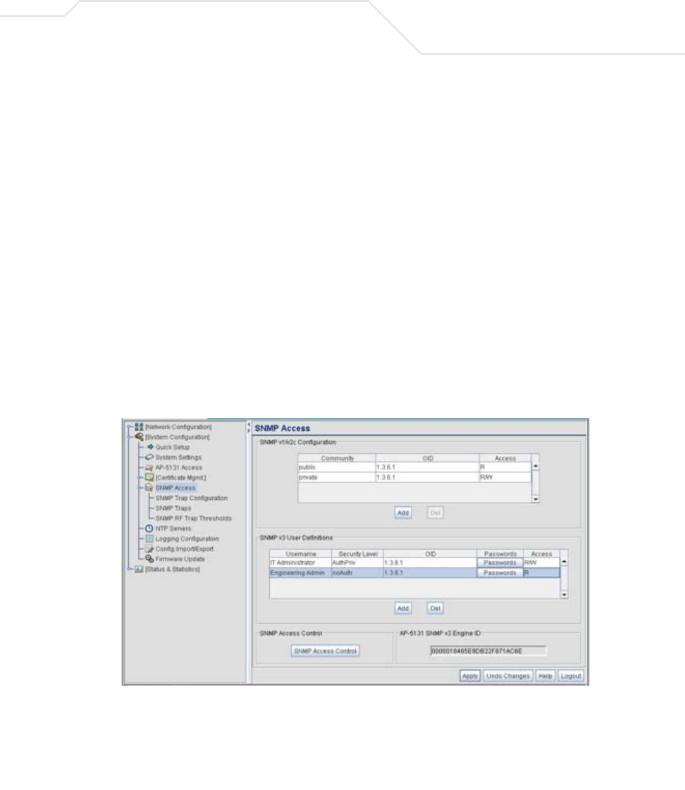
Use the SNMP Access screen to define SNMP v1/v2c community definitions and SNMP v3 user
definitions. SNMP version 1 (v1) provides a strong network management system, but its security is
relatively weak. The improvements in SNMP version 2c (v2c) do not include the attempted security
enhancements of other version-2 protocols. Instead, SNMP v2c defaults to SNMP-standard
community strings for read-only and read/write access. SNMP version 3 (v3) further enhances
protocol features, providing much improved security. SNMP v3 encrypts transmissions and provides
authentication for users generating requests.
To configure SNMP v1/v2c community definitions and SNMP v3 user definitions for the access point:
1. Select System Configuration - > SNMP Access from the access point menu tree.
SNMP v1/v2c community definitions allow read-only or read/write access to access point
management information. The SNMP community includes users whose IP addresses are
specified on the SNMP Access Control screen.
A read-only community string allows a remote device to retrieve information, while a read/
write community string allows a remote device to modify settings. Symbol recommends

AP-51xx Access Point Product Reference Guide
4-20
considering adding a community definition using a site-appropriate name and access level.
Set up a read/write definition (at a minimum) to facilitate full access by the access point
administrator.
2. Configure the SNMP v1/v2 Configuration field (if SNMP v1/v2 is used) to add or delete
community definitions, name the community, specify the OID and define community access.
3. Configure the SNMP v3 User Definitions field (if SNMP v3 is used) to add and configure
SNMP v3 user definitions.
SNMP v3 user definitions allow read-only or read/write access to management information
as appropriate.
Add Click Add to create a new SNMP v1/v2c community definition.
Delete Select Delete to remove a SNMP v1/v2c community definition.
Community Use the Community field to specify a site-appropriate name for
the community. The name is required to match the name used
within the remote network management software.
OID Use the OID (Object Identifier) pull-down list to specify a setting of
All or a enter a Custom OID. Select All to assign the user access to
all OIDs in the MIB. The OID field uses numbers expressed in dot
notation.
Access Use the Access pull-down list to specify read-only (R) access or
read/write (RW) access for the community. Read-only access
allows a remote device to retrieve access point information, while
read/write access allows a remote device to modify access point
settings.
Add Click Add to create a new entry for an SNMP v3 user.
Delete Select Delete to remove an entry for an SNMP v3 user.
Username Specify a username by typing an alphanumeric string of up to 31
characters.

System Configuration 4-21
4. Specify the users who can read and optionally modify the SNMP-capable client.
Security Level Use the Security Level area to specify a security level of noAuth
(no authorization), AuthNoPriv (authorization without privacy), or
AuthPriv (authorization with privacy).
The NoAuth setting specifies no login authorization or encryption
for the user.
The AuthNoPriv setting requires login authorization, but no
encryption.
The AuthPriv setting requires login authorization and uses the
Data Encryption Standard (DES) protocol.
OID Use the OID (Object Identifier) area to specify a setting of All or
enter a Custom OID. Select All to assign the user access to all OIDs
in the MIB. The OID field uses numbers expressed in dot notation.
Passwords Select Passwords to display the Password Settings screen for
specifying authentication and password settings for an SNMP v3
user. The maximum password length is 11 characters. Use the
Authentication Algorithm drop-down menu to specify MD5 or
SHA1 as the authentication algorithm. Use the Privacy Algorithm
drop-down menu to define an algorithm of DES or AES-128bit.
When entering the same username on the SNMP Traps and
SNMP Access screens, the password entered on the SNMP Traps
page overwrites the password entered on the SNMP Access page.
To avoid this problem, enter the same password on both pages.
Access Use the Access pull-down list to specify read-only (R) access or
read/write (RW) access for a user. Read-only access permits a user
to retrieve access point information, while read/write access
allows a user to modify access pointsettings.

AP-51xx Access Point Product Reference Guide
4-22
5. If configuring SNMP v3 user definitions, set the SNMP v3 engine ID.
6. Click Apply to save any changes to the SNMP Access screen. Navigating away from the
screen without clicking the Apply button results in all changes to the screen being lost.
7. Click Undo Changes (if necessary) to undo any changes made. Undo Changes reverts the
settings displayed on the SNMP Access screen to the last saved configuration.
8. Click Logout to securely exit the access point Symbol Access Point applet. A prompt
displays confirming the logout before the applet is closed.
For additional SNMP configuration information, see:
•Configuring SNMP Access Control
•Enabling SNMP Traps
•Configuring Specific SNMP Traps
•Configuring SNMP RF Trap Thresholds
4.4.1 Configuring SNMP Access Control
Use the SNMP Access Control screen (as launched from the SNMP Access screen) to specify
which users can read SNMP generated information and, if capable, modify related settings from an
SNMP-capable client.
SNMP Access Control Click the SNMP Access Control button to display the SNMP
Access Control screen for specifying which users can read
SNMP-generated information and potentially modify related
settings from an SNMP-capable client.
The SNMP Access Control screen's Access Control List (ACL) uses
Internet Protocol (IP) addresses to restrict access to the AP’s SNMP
interface. The ACL applies to both SNMP v3 user definitions and
SNMP v1/v2c community definitions.
For detailed instructions of configuring SNMP user access and
modification privileges, see Configuring SNMP Access Control on
page 4-22.
access point SNMP
v3 Engine ID
The access point SNMP v3 Engine ID field lists the unique
SNMP v3 Engine ID for the access point. This ID is used in SNMP
v3 as the source for a trap, response or report. It is also used as the
destination ID when sending get, getnext, getbulk, set or inform
commands.
System Configuration 4-23
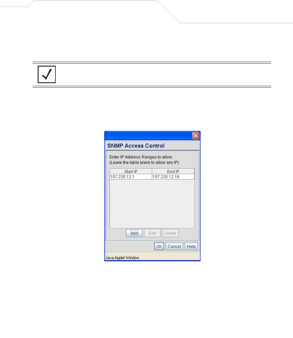
Use the SNMP Access Control screen's Access Control List (ACL) to limit, by Internet Protocol (IP)
address, who can access the access point SNMP interface.
To configure SNMP user access control for the access point:
1. Select System Configuration - > SNMP Access from the access point menu tree. Click
on the SNMP Access Control button from within the SNMP Access screen.
2. Configure the SNMP Access Control screen to add the IP addresses of those users receiving
SNMP access.
NOTE The ACL applies to both SNMP v3 user definitions and SNMP v1/v2c
community definitions on the access point SNMP Access screen.

AP-51xx Access Point Product Reference Guide
4-24
4.4.2 Enabling SNMP Traps
SNMP provides the ability to send traps to notify the administrator that trap conditions are met. Traps
are network packets containing data relating to network devices, or SNMP agents, that send the
traps. SNMP management applications can receive and interpret these packets, and optionally can
perform responsive actions. SNMP trap generation is programmable on a trap-by-trap basis.
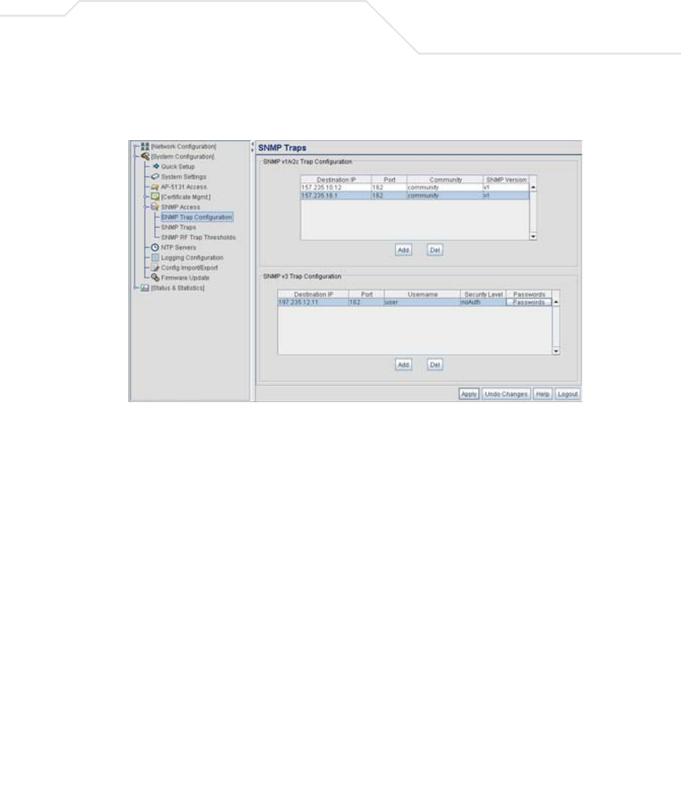
Use the SNMP Traps Configuration screen to enable traps and to configure appropriate settings
for reporting this information. Trap configuration depends on the network machine that receives the
generated traps. SNMP v1/v2c and v3 trap configurations function independently. In a mixed SNMP
environment, generated traps can be sent using configurations for both SNMP v1/v2c and v3.
To configure SNMP traps on the access point:
Access Control List Enter Start IP and End IP addresses (numerical addresses only, no
DNS names supported) to specify a range of user that can access
the access point SNMP interface. An SNMP-capable client can be
set up whereby only the administrator (for example) can use a read/
write community definition.
Use just the Starting IP Address column to specify a single SNMP
user. Use both the Starting IP Address and Ending IP Address
columns to specify a range of addresses for SNMP users.
To add a single IP address to the ACL, enter the same IP address in
the Start IP and End IP fields.
Leave the ACL blank to allow access to the SNMP interface from
the IP addresses of all authorized users.
Add Click Add to create a new ACL entry.
Edit Click Edit to revise an existing ACL entry.
Delete Click Delete to remove a selected ACL entry for one or more SNMP
users.
OK Click Ok to return to the SNMP Access screen. Click Apply within
the SNMP Access screen to save any changes made on the SNMP
Access Control screen.
Cancel Click Cancel to undo any changes made on the SNMP Access
Control screen. This reverts all settings for this screen to the last
saved configuration.
System Configuration 4-25
1. Select System Configuration - > SNMP Access - > SNMP Trap Configuration from the
access point menu tree.
2. Configure the SNMP v1/v2c Trap Configuration field (if SNMP v1/v2c Traps are used) to
modify the following:
3. Configure the SNMP v3 Trap Configuration field (if SNMP v3 Traps are used) to modify
the following:
Add Click Add to create a new SNMP v1/v2c Trap Configuration entry.
Delete Click Delete to remove a selected SNMP v1/v2c Trap
Configuration entry.
Destination IP Specify a numerical (non DNS name) destination IP address for
receiving the traps sent by the access point SNMP agent.
Port Specify a destination User Datagram Protocol (UDP) port for
receiving traps. The default is 162.
Community Enter a community name specific to the SNMP-capable client that
receives the traps.
SNMP Version Use the SNMP Version drop-down menu to specify v1 or v2.
Some SNMP clients support only SNMP v1 traps, while others
support SNMP v2 traps and possibly both, verify the correct traps
are in use with clients that support them.

AP-51xx Access Point Product Reference Guide
4-26
4. Click Apply to save any changes to the SNMP Trap Configuration screen. Navigating away
from the screen without clicking the Apply button results in all changes to the screen being
lost.
5. Click Undo Changes (if necessary) to undo any changes made. Undo Changes reverts the
settings displayed on SNMP Trap Configuration screen to the last saved configuration.
6. Click Logout to securely exit the access point Symbol Access Point applet. A prompt
displays confirming the logout before the applet is closed.
Add Click Add to create a new SNMP v3 Trap Configuration entry.
Delete Select Delete to remove an entry for an SNMP v3 user.
Destination IP Specify a numerical (non DNS name) destination IP address for
receiving the traps sent by the access point SNMP agent.
Port Specify a destination User Datagram Protocol (UDP) port for
receiving traps.
Username Enter a username specific to the SNMP-capable client receiving
the traps.
Security Level Use the Security Level drop-down menu to specify a security
level of noAuth (no authorization), AuthNoPriv (authorization
without privacy), or AuthPriv (authorization with privacy).
The “NoAuth” setting specifies no login authorization or encryption
for the user. The “AuthNoPriv” setting requires login authorization,
but no encryption. The “AuthPriv” setting requires login
authorization and uses the Data Encryption Standard (DES).
Passwords Select Passwords to display the Password Settings screen for
specifying authentication and password settings for an SNMP v3
user. The maximum password length is 11 characters. Use the
Authentication Algorithm drop-down menu to specify MD5 or
SHA1 as the authentication algorithm. Use the Privacy Algorithm
drop-down menu to define an algorithm of DES or AES-128bit.
If entering the same username on the SNMP Traps and SNMP
Access screens, the password entered on the SNMP Traps page
overwrites the password entered on the SNMP Access page. To
avoid this problem, enter the same password on both pages.
System Configuration 4-27
4.4.3 Configuring Specific SNMP Traps
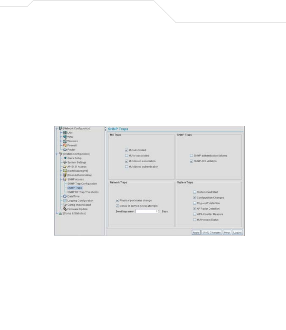
Use the SNMP Traps screen to enable specific traps on the access point. Symbol recommends
defining traps to capture unauthorized devices operating within the access point coverage area. Trap
configuration depends on the network machine that receives the generated traps. SNMP v1/v2c and
v3 trap configurations function independently. In a mixed SNMP environment, traps can be sent using
configurations for both SNMP v1/v2c and v3.
To configure specific SNMP traps on the access point:
1. Select System Configuration - > SNMP Access - > SNMP Traps from the access point
menu tree.
2. Configure the MU Traps field to generate traps for MU associations, MU association
denials and MU authentication denials. When a trap is enabled, a trap is sent every 10
seconds until the condition no longer exists.
MU associated Generates a trap when an MU becomes associated with one of the
access point’s WLANs.
MU unassociated Generates a trap when an MU becomes unassociated with (or gets
dropped from) one of the access point’s WLANs.

AP-51xx Access Point Product Reference Guide
4-28
3. Configure the SNMP Traps field to generate traps when SNMP capable MUs are denied
authentication privileges or are subject of an ACL violation. When a trap is enabled, a trap
is sent every 5 seconds until the condition no longer exists.
4. Configure the Network Traps field to generate traps when the access point’s link status
changes or when the AP’s firewall detects a DOS attack.
5. Configure the System Traps field to generate traps when the access point re-initializes
during transmission, saves its configuration file. When a trap is enabled, a trap is sent every
5 seconds until the condition no longer exists.
MU denied
association
Generates a trap when an MU is denied association to a access
point WLAN. Can be caused when the maximum number of MUs
for a WLAN is exceeded or when an MU violates the access
point’s Access Control List (ACL).
MU denied
authentication
Generates a trap when an MU is denied authentication on one of
the AP’s WLANs. Can be caused by the MU being set for the wrong
authentication type for the WLAN or by an incorrect key or
password.
SNMP authentication
failures
Generates a trap when an SNMP-capable client is denied access
to the access point’s SNMP management functions or data. This
can result from an incorrect login, or missing/incorrect user
credentials.
SNMP ACL violation Generates a trap when an SNMP client cannot access SNMP
management functions or data due to an Access Control List (ACL)
violation. This can result from a missing/incorrect IP address
entered within the SNMP Access Control screen.
Physical port status
change
Generates a trap whenever the status changes on the access
point. The physical port status changes when a link is lost between
the access point and a connected device.
Denial of service
(DOS) attempts
Generates a trap whenever a Denial of Service (DOS) attack is
detected by the access point firewall. A new trap is sent at the
specified interval until the attack has stopped.
Send trap every Defines the interval in seconds the access point uses to generate
a trap until the Denial of Service attack is stopped. Default is 10
seconds.

System Configuration 4-29
6. Click Apply to save any changes to the SNMP Traps screen. Navigating away from the
screen without clicking the Apply button results in all changes to the screen being lost.
7. Click Undo Changes (if necessary) to undo any changes made. Undo Changes reverts the
settings displayed on SNMP Traps screen to the last saved configuration.
8. Click Logout to securely exit the access point Symbol Access Point applet. A prompt
displays confirming the logout before the applet is closed.
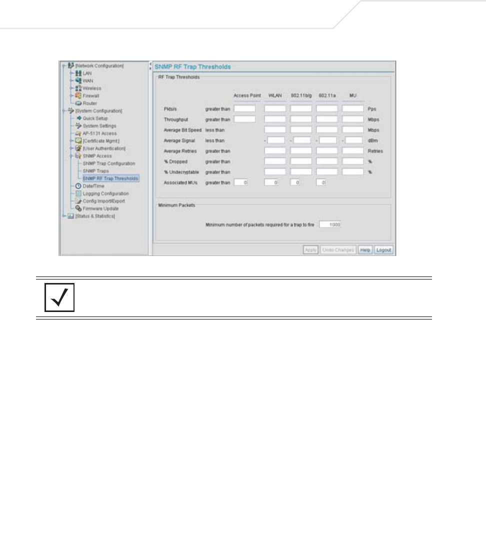
4.4.4 Configuring SNMP RF Trap Thresholds
Use the SNMP RF Trap Threshold screen as a means to track RF activity and the access point’s
radio and associated MU performance. SNMP RF Traps are sent when RF traffic exceeds defined
limits set in the RF Trap Thresholds field of the SNMP RF Traps screen. Thresholds are displayed
for the access point, WLAN, selected radio and the associated MU.
To configure specific SNMP RF Traps on the access point:
1. Select System Configuration - > SNMP Access - > SNMP RF Trap Thresholds from
the access point menu tree.
System Cold Start Generates a trap when the access point re-initializes while
transmitting, possibly altering the SNMP agent's configuration or
protocol entity implementation.
Configuration
Changes
Generates a trap whenever changes to the access point’s
configuration file are saved.
Rogue AP detection Generates a trap if a Rogue AP is detected by the access point.
AP Radar detection Generates a trap if an AP is detected using a form of radar
detection.
WPA Counter
Measure
Generates a trap if an attack is detected against the WPA Key
Exchange Mechanism.
MU Hotspot Status Generates a trap when a change to the status of MU hotspot
member is detected.
AP-51xx Access Point Product Reference Guide
4-30
2. Configure the RF Trap Thresholds field to define device threshold values for SNMP traps.
NOTE Average Bit Speed,% of Non-Unicast, Average Signal, Average Retries,%
Dropped and % Undecryptable are not access point statistics.
Pkts/s Enter a maximum threshold for the total throughput in Pps (Packets
per second).
Throughput Set a maximum threshold for the total throughput in Mbps
(Megabits per second).
Average Bit Speed Enter a minimum threshold for the average bit speed in Mbps
(Megabits per second).
Average Signal Enter a minimum threshold for the average signal strength in dBm
for each device.
Average Retries Set a maximum threshold for the average number of retries for
each device.
% Dropped Enter a maximum threshold for the total percentage of packets
dropped for each device. Dropped packets can be caused by poor
RF signal or interference on the channel.

System Configuration 4-31
3. Configure the Minimum Packets field to define a minimum packet throughput value for
trap generation.
4. Click Apply to save any changes to the SNMP RF Traps screen. Navigating away from the
screen without clicking the Apply button results in all changes to the screen being lost.
5. Click Undo Changes (if necessary) to undo any changes made. Undo Changes reverts the
settings displayed on SNMP RF Traps screen to the last saved configuration.
6. Click Logout to securely exit the access point Symbol Access Point applet. A prompt
displays confirming the logout before the applet is closed.
4.5 Configuring Network Time Protocol (NTP)
Network Time Protocol (NTP) manages time and/or network clock synchronization in the access point-
managed network environment. NTP is a client/server implementation. The access point (an NTP
client) periodically synchronizes its clock with a master clock (an NTP server). For example, the access
point resets its clock to 07:04:59 upon reading a time of 07:04:59 from its designated NTP server.
Time synchronization is recommended for the access point’s network operations. For sites using
Kerberos authentication, time synchronization is required.
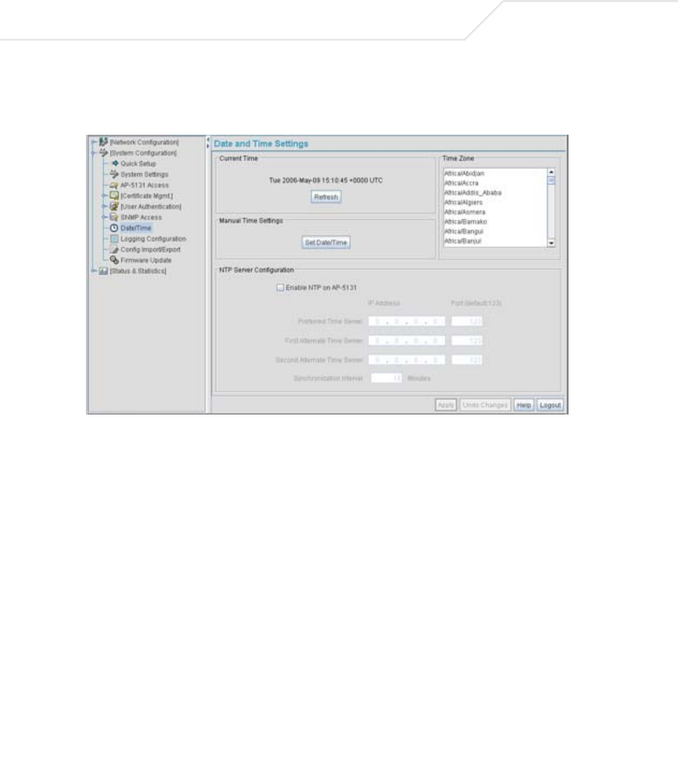
Use the Date and Time Settings screen to enable NTP and specify the IP addresses and ports of
available NTP servers.
% Undecryptable Define a maximum threshold for the total percentage of packets
undecryptable for each device. Undecryptable packets can be the
result of corrupt packets, bad CRC checks or incomplete packets.
Associated MUs Set a maximum threshold for the total number of MUs associated
with each device.
Minimum number of
packets required for a
trap to fire
Enter the minimum number of packets that must pass through the
device before an SNMP rate trap is sent. Symbol recommends
using the default setting of 1000 as a minimum setting for the field.
NOTE The current time is not set accurately when initially connecting to the
access point. Until a server is defined to provide the access point the
correct time, or the correct time is manually set, the access point displays
1970-01-01 00:00:00 as the default time.
AP-51xx Access Point Product Reference Guide
4-32
To manage clock synchronization on the access point:
1. Select System Configuration - > Date/Time from the access point menu tree.
2. From within the Current Time field, click the Refresh button to update the time since the
screen was displayed by the user.
The Current Time field displays the current time based on the access point system clock. If
NTP is disabled or if there are no servers available, the system time displays the access
point uptime starting at 1970-01-01 00:00:00, with the time and date advancing.
3. Select the Set Date/Time button to display the Manual Date/Time Setting screen.
This screen enables the user to manually enter the access point’s system time using a
Year-Month-Day HH:MM:SS format.
This option is disabled when the Enable NTP checkbox has been selected, and therefore
should be viewed as a second means to define the access point system time.
4. If using the Manual Date/Time Setting screen to define the access point’s system time, refer
to the Time Zone field to select the time used to use as complimentary information to the
information entered within the Manual Date/Time Setting screen.
5. If using an NTP server to supply system time to the access point, configure the NTP Server
Configuration field to define the server network address information required to acquire
the access point network time.

System Configuration 4-33
6. Click Apply to save any changes to the Date and time Settings screen. Navigating away
from the screen without clicking the Apply button results in all changes to the screen being
lost.
7. Click Undo Changes (if necessary) to undo any changes made. Undo Changes reverts the
settings displayed on Date and Time Settings screen to the last saved configuration.
8. Click Logout to securely exit the access point Symbol Access Point applet. A prompt
displays confirming the logout before the applet is closed.
Enable NTP on access
point
Select the Enable NTP on access point checkbox to allow a
connection between the access point and one or more specified
NTP servers. A preferred, first alternate and second alternate NTP
server cannot be defined unless this checkbox is selected.
Disable this option (uncheck the checkbox) if Kerberos is not in use
and time synchronization is not necessary.
Preferred Time Server Specify the numerical (non DNS name) IP address and port of the
primary NTP server. The default port is 123.
First Alternate Time
Server
Optionally, specify the numerical (non DNS name) IP address and
port of an alternative NTP server to use for time synchronization if
the primary NTP server goes down.
Second Alternate
Time Server
Optionally, specify the numerical (non DNS name) and port of yet
another NTP server for the greatest assurance of uninterrupted
time synchronization.
Synchronization
Interval
Define an interval in minutes the access point uses to synchronize
its system time with the NTP server. A synchronization interval
value from 15 minutes to 65535 minutes can be specified. For
implementations using Kerberos, a synchronization interval of 15
minutes (default interval) or sooner is recommended.
AP-51xx Access Point Product Reference Guide
4-34
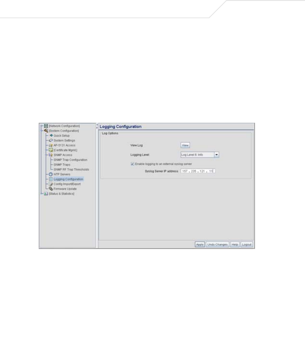
4.6 Logging Configuration
The access point provides the capability for periodically logging system events that prove useful in
assessing the throughput and performance of the access point or troubleshooting problems on the
access point managed Local Area Network (LAN). Use the Logging Configuration screen to set the
desired logging level (standard syslog levels) and view or save the current access point system log.
To configure event logging for the access point:
1. Select System Configuration - > Logging Configuration from the access point menu
tree.
2. Configure the Log Options field to save event logs, set the log level and optionally port the
access point’s log to an external server.

System Configuration 4-35
3. Click Apply to save any changes to the Logging Configuration screen. Navigating away from
the screen without clicking the Apply button results in all changes to the screen being lost.
View Log Click View to save a log of events retained on the access point.
The system displays a prompt requesting the administrator
password before saving the log. After the password has been
entered, click Get File to display a dialogue with buttons to Open
or Save the log.txt file. Click Save and specify a location to save
the log file.
Use the WordPad application to view the saved log.txt file on a
Microsoft Windows based computer. Do not view the log file using
Notepad, as the Notepad application does not properly display the
formatting of the access point log file. Log entries are not saved
in the access point. While the AP is in operation, log data
temporarily resides in memory. AP memory is completely cleared
each time the AP reboots.
Logging Level Use the Logging Level drop-down menu to select the desired log
level for tracking system events. Eight logging levels, (0 to 7) are
available. Log Level 6: Info is the access point default log level.
These are the standard UNIX/LINUX syslog levels.The levels are as
follows:
0 - Emergency
1 - Alert
2 - Critical
3 - Errors
4 - Warning
5 - Notice
6 - Info
7 - Debug
Enable logging to an
external syslog server
The access point can log events to an external syslog (system log)
server. Select the Enable logging to an external syslog server
checkbox to enable the server to listen for incoming syslog
messages and decode the messages into a log for viewing.
Syslog server IP
address
If the Enable logging to an external syslog server checkbox is
selected, the numerical (non DNS name) IP address of an
external syslog server is required in order to route the syslog events
to that destination.
AP-51xx Access Point Product Reference Guide
4-36
4. Click Undo Changes (if necessary) to undo any changes made. Undo Changes reverts the
settings displayed on the Logging Configuration screen to the last saved configuration.
5. Click Logout to securely exit the access point Symbol Access Point applet. A prompt
displays confirming the logout before the applet is closed.
4.7 Importing/Exporting Configurations
All of the configuration settings for an access point can be obtained from another access point in the
form of a text file. Additionally, all of the access point’s settings can be downloaded to another access
point. Use the file-based configuration feature to speed up the setup process significantly at sites
using multiple access points.
Another benefit is the opportunity to save the current AP configuration before making significant
changes or restoring the default configuration. All options on the access point are deleted and
updated by the imported file. Therefore, the imported configuration is not a merge with the
configuration of the target access point. The exported file can be edited with any document editor if
necessary.
The export function will always export the encrypted Admin User password. The import function will
import the Admin Password only if the access point is set to factory default. If the access point is not
configured to factory default settings, the Admin User password WILL NOT get imported.
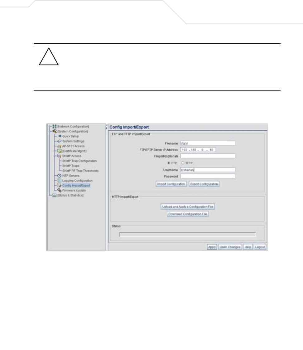
Use the Config Import/Export screen to configure an import or export operation for access point
configuration settings.
CAUTION A single-radio model access point cannot import/export its
configuration to a dual-radio model access point. In turn, a dual-radio
model access point cannot import/export its configuration to a single-
radio access point.
NOTE Use the System Settings screen as necessary to restore an access point
default configuration. For more information on restoring configurations,
see Configuring System Settings on page 4-2.
!
System Configuration 4-37
To create an importable/exportable access point configuration file:
1. Select System Configuration - > Config Import/Export from the access point menu tree.
2. Configure the FTP and TFTP Import/Export field to import/export configuration settings.
CAUTION Symbol discourages importing a 1.0 baseline configuration file to a
1.1 version access point. Similarly, a 1.1 baseline configuration file
should not be imported to a 1.0 version access point. Importing
configuration files between different version access point’s results in
broken configurations, since new features added to the 1.1 version
access point cannot be supported in a 1.0 version access point.
Filename Specify the name of the configuration file to be written to the FTP
or TFTP server.
Server IP Enter the numerical (non DNS name) IP address of the
destination FTP or TFTP server where the configuration file is
imported or exported.
Filepath (optional) Defines the optional path name used to import/export the target
configuration file.
FTP Select the FTP radio button if using an FTP server to import or export
the configuration.
!

AP-51xx Access Point Product Reference Guide
4-38
3. Configure the HTTP Import/Export field to import/export access point configuration
settings using HTTP.
TFTP Select the TFTP radio button if using an FTP server to import or
export the configuration.
Username Specify a username to be used when logging in to the FTP server. A
username is not required for TFTP server logins.
Password Define a password allowing access to the FTP server for the import
or export operation.
Import Configuration Click the Import Configuration button to import the configuration
file from the server with the assigned filename and login
information. The system displays a confirmation window indicating
the administrator must log out of the access point after the
operation completes for the changes to take effect. Click Yes to
continue the operation. Click No to cancel the configuration file
import.
Export Configuration Click the Export Configuration button to export the configuration
file from the server with the assigned filename and login
information. If the IP mode is set to DHCP Client, IP address
information is not exported (true for both LAN1, LAN2 and the
WAN port). For LAN1 and LAN2, IP address information is only
exported when the IP mode is set to either static or DHCP Server.
For the WAN port, IP address information is only exported when the
This interface is a DHCP Client checkbox is not selected. For
more information on these settings, see
Configuring the LAN Interface on page 5-1 and
Configuring WAN Settings on page 5-14.
The system displays a confirmation window prompting the
administrator to log out of the access point after the operation
completes for the changes to take effect. Click Yes to continue the
operation. Click No to cancel the configuration file export.
CAUTION For HTTP downloads (exports) to be successful, pop-up messages
must be disabled.
!

System Configuration 4-39
4. Refer to the Status field to assess the completion of the import/export operation.
Upload and Apply A
Configuration File
Click the Upload and Apply A Configuration File button to
upload a configuration file to this access point using HTTP.
Download
Configuration File
Click the Download Configuration File button to download this
access point’s configuration file using HTTP.
Status After executing an operation (by clicking any of the buttons in the
window), check the Status field for a progress indicator and
messages about the success or errors in executing the Import/
Export operation. Possible status messages include:
ambiguous input before marker: line <number >
unknown input before marker: line <number>
ignored input after marker: line <number>
additional input required after marker: line <number>
invalid input length: line <number>
error reading input: line <number>
import file from incompatible hardware type: line <number>
[0] Import operation done
[1] Export operation done
[2] Import operation failed
[3] Export operation failed
[4] File transfer in progress
[5] File transfer failed
[6] File transfer done
Auto cfg update: Error in applying config
Auto cfg update: Error in getting config file
Auto cfg update: Aborting due to fw update failure
The <number> value appearing at the end of some messages
relates to the line of the configuration file where an error or
ambiguous input was detected.
AP-51xx Access Point Product Reference Guide
4-40
5. Click Apply to save the filename and Server IP information. The Apply button does not
execute the import or export operation, only saves the settings entered.
6. Click Undo Changes (if necessary) to undo any changes made. Undo Changes reverts the
settings displayed on Config Import/Export screen to the last saved configuration.
7. Click Logout to securely exit the access point Symbol Access Point applet. A prompt
displays confirming the logout before the applet is closed.
4.8 Updating Device Firmware
Symbol periodically releases updated versions of the access point device firmware to the Symbol
Web site. If the access point firmware version displayed on the System Settings page (see
Configuring System Settings on page 4-2) is older than the version on the Web site, Symbol
recommends updating the access point to the latest firmware version for full feature functionality.
The access point’s update feature updates the access point’s firmware and configuration file
automatically when the access point is reset or when the access point initiates a DHCP discovery.
The firmware is automatically updated each time firmware versions are found to be different
between the access point and the firmware file located on the DHCP/BootP server. If the
CAUTION If errors occur when importing the configuration file, a parsing
message displays defining the line number where the error occurred.
The configuration is still imported, except for the error. Consequently,
it is possible to import an invalid configuration. The user is required to
fix the problem and repeat the import operation until an error-free
import takes place.
NOTE Symbol recommends importing configuration files using the CLI. If errors
occur using the CLI, they display all at once and are easier to troubleshoot.
The access point GUI displays errors one at a time, and troubleshooting
can be a more time-consuming process.
NOTE For a discussion on the implications of replacing an existing Symbol
AP-4131 deployment with an AP-5131 or AP-5181, see
Replacing an AP-4131 with an AP-5131 or AP-5181 on page B-18.
!
System Configuration 4-41
configuration file is selected for automatic update, the configuration is automatically updated since
the access point is unable to compare the differences between configuration files.
For detailed update scenarios involving both a Windows DHCP and a Linux BootP server
configuration, see Configuring Automatic Updates using a DHCP or Linux BootP Server Configuration
on page B-1.
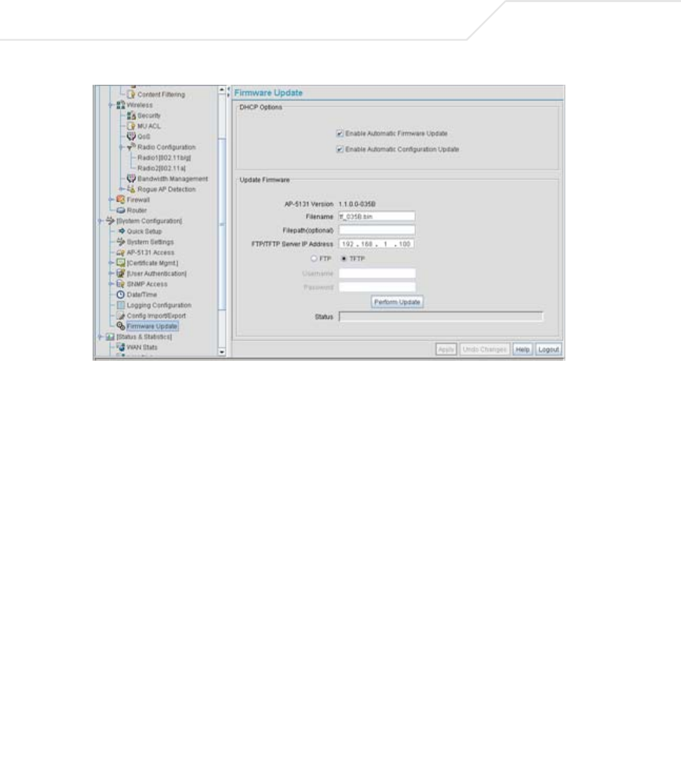
If a firmware update is required, use the Firmware Update screen to specify a filename and define
a file location for updating the firmware.
To conduct a firmware update on the access point:
1. Export the access point current configuration settings before updating the firmware to have
the most recent settings available after the firmware is updated.
Refer to Importing/Exporting Configurations on page 4-36 for instructions on exporting the
access point’s current configuration to have it available after the firmware is updated.
2. Select System Configuration - > Firmware Update from the access point menu tree.
CAUTION If downgrading firmware from a 1.1 to a 1.0 version, the access point
automatically reverts to 1.0 default settings, regardless of whether
you are downloading the firmware manually or using the automatic
download feature. The automatic feature allows the user to download
the configuration file at the same time, but since the firmware reverts
to 1.0 default settings, the configuration file is ignored.
CAUTION Loaded and signed CA certificates will be lost when changing the
access point’s firmware version using either the GUI or CLI. After a
certificate has been successfully loaded, export it to a secure location
to ensure its availability after a firmware update.
NOTE The firmware file must be available from an FTP or TFTP site to perform
the update.
CAUTION Make sure a copy of the access point’s configuration is exported
before updating the firmware.
!
!
!
AP-51xx Access Point Product Reference Guide
4-42
3. Configure the DHCP Options field to enable automatic firmware and/or configuration file
updates.
DHCP options are used for out-of-the-box rapid deployment for Symbol wireless products.
The following are the two DHCP options available on the access point:
• Enable Automatic Firmware Update
• Enable Automatic Configuration Update
These options can be used to update newer firmware and configuration files on the
access point. The access point uses DHCP Vendor Specific Option 43 with the following
options embedded within it:
The Vendor Class Identifier used is SymbolAP.5131-V1-0
The DHCP Server needs to be configured with the above mentioned vendor specific options
and vendor class identifier. The update is conducted over the LAN or WAN port depending
on which is the active port at the time the firmware update request is made.
Option Code Data Type
TFTP Server Name 181 IP address
Firmware File Name 187 String
Configuration File Name 188 String

System Configuration 4-43
Configure the Update Firmware field as required to set a filename and target firmware file
upload location for manual firmware updates.
4. Specify the name of the target firmware file within the Filename field.
5. If the target firmware file resides within a directory, specify a complete path for the file
within the Filepath(optional) field.
6. Enter an IP address for the FTP or TFTP server used for the update. Only numerical IP address
names are supported, no DNS can be used.
7. Select either the FTP or TFTP button to define whether the firmware file resides on a FTP or
TFTP server.
8. Set the following FTP or TFTP parameters:
•Username - Specify a username for the FTP server login.
•Password - Specify a password for FTP server login. Default is symbol.
Enable Automatic
Firmware Update
Select this checkbox to allow an automatic firmware update each
time firmware versions are found to be different between the
access point and the LAN or WAN interface. This option is used
in conjunction with other DHCP options configured on a DHCP
server.
Symbol recommends selecting the Enable Automatic
Configuration Update checkbox if auto-updating access point
firmware, as backing up the access point configuration is always
recommended before updating device firmware. If this function is
disabled, the firmware update is required to be done manually. If
this option is enabled, the access point initiates an update any time
the access point reboots. If the files located on the DHCP server are
different from the existing files on the access point, the files are
updated. The default setting is enabled on the WAN port.
Enable Automatic
Configuration Update
Select this checkbox to allow an automatic configuration file
update each time the configuration file versions are found to be
different between the access point and the LAN or WAN
interface. If this function is disabled, the configuration file update
is required to be done manually. If this function is disabled, the
firmware update is required to be done manually. If this option is
enabled, the access point initiates an update any time the access
point reboots. If the files located on the DHCP server are different
from the existing files on the access point, the files are updated.
The default setting is enabled on the WAN port.
AP-51xx Access Point Product Reference Guide
4-44
9. Click the Perform Update button to initiate the update. Upon confirming the firmware
update, the AP reboots and completes the update.
10. After the AP reboots, return to the Firmware Update screen. Check the Status field to verify
whether the firmware update was successful. If an error occurs, one of the following error
messages will display:
FAIL: auto fw update check
FAIL: network activity time out
FAIL: firmware check
FAIL: exceed memory limit
FAIL: authentication
FAIL: connection time out
FAIL: control channel error
FAIL: data channel error
FAIL: channel closed unexpected
FAIL: establish data channel
FAIL: accept data channel
FAIL: user interrupted
FAIL: no valid interface found
FAIL: conflict ip address
FAIL: command exchange time out
FAIL: invalid subnet number
11. Confirm the access point configuration is the same as it was before the firmware update. If
they are not, restore the settings. Refer to Importing/Exporting Configurations on page 4-36
for instructions on exporting the configuration back to the access point.
NOTE Click Apply to save the settings before performing the firmware update.
The user is not able to navigate the access point user interface while the
firmware update is in process.
NOTE The access point must complete the reboot process to successfully update
the device firmware, regardless of whether the reboot is conducted using
the GUI or CLI interfaces.

System Configuration 4-45
12. Click Apply to save the filename and filepath information entered into the Firmware Update
screen. The Apply button does not execute the firmware, only saves the update settings
entered.
13. Click Undo Changes (if necessary) to undo any changes made. Undo Changes reverts the
settings displayed on Firmware Update screen to the last saved configuration.
14. Click Logout to securely exit the access point Symbol Access Point applet. A prompt
displays confirming the logout before the applet is closed.
4.8.1 Upgrade/Downgrade Considerations
When upgrading or downgrading access point configurations between the 1.0.0.0-XX (or 1.0.1.0-XX)
and 1.1.0.0-XX baselines, the following should be taken into consideration as certain functionalities
may not be available to the user after an upgrade/downgrade:
• When downgrading from 1.1 to 1.0, the access point is configured to default values.
• After a downgrade from 1.1.0.0-XX to 1.0.0.0-XX, WLANs mapped to LAN2 would still be
usable, but now only available on LAN1. Once upgraded back to 1.1.0.0-XX, those WLANs
previously available on LAN2 would still be mapped to LAN2.
• If downgraded to the 1.0.0.0-XX baseline, and a restore factory defaults function is
performed, only 1.0.0.0-XX default values are restored to their factory default values. The
feature set unique to 1.1.0.0-XX can only be restored to factory default when the access
point is running 1.1.0.0-XX firmware.
• Export either a CA or Self Certificate to a safe and secure location before upgrading or
downgrading your access point firmware. If the certificate is not saved, it will be discarded
and not available to the user after the upgrade or downgrade. If discarded, a new certificate
request would be required.
CAUTION Prior to upgrading/downgrading the access point’s configuration,
ensure the access point’s current configuration has been exported to a
secure location. Having the configuration available is recommended in
case errors occur in the upgrade/downgrade process.
NOTE For a discussion on the implications of replacing an existing Symbol
AP-4131 deployment with an AP-5131 or AP-5181, see
Replacing an AP-4131 with an AP-5131 or AP-5181 on page B-18.
!

AP-51xx Access Point Product Reference Guide
4-46

Network Management
Configuring network management includes configuring network aspects in numerous areas. See
the following sections for more information on access point network management:
•Configuring the LAN Interface
•Configuring WAN Settings
•Enabling Wireless LANs (WLANs)
•Configuring Router Settings
5.1 Configuring the LAN Interface
The access point has one physical LAN port supporting two unique LAN interfaces. The access
point LAN port has its own MAC address. The LAN port MAC address is always the value of the
access point WAN port MAC address plus 1. The LAN and WAN port MAC addresses can be
located within the LAN and WAN Stats screens.
For information on locating the access point MAC addresses, see
Viewing WAN Statistics on page 7-2 and Viewing LAN Statistics on page 7-6.
AP-51xx Access Point Product Reference Guide
5-2
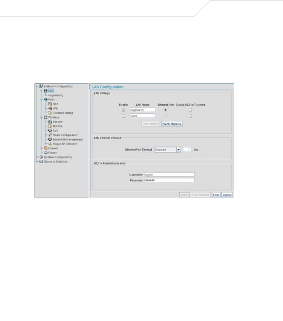
Use the LAN Configuration screen to enable one (or both) of the access point’s LAN interfaces,
assign them names, define which LAN is currently active on the access point Ethernet port and assign
a timeout value to disable the LAN connection if no data traffic is detected within a defined interval.
To configure the access point LAN interface:
1. Select Network Configuration -> LAN from the access point menu tree.
2. Configure the LAN Settings field to enable the access point LAN1 and/or LAN2 interface,
assign a timeout value, enable 802.1q trunking, configure WLAN mapping and enable
802.1x port authentication.
Enable Select the LAN1 and/or LAN2 checkbox to allow the forwarding of
data traffic over the specified LAN connection. The LAN1
connection is enabled by default, but both LAN interfaces can be
enabled simultaneously.
LAN Name Use the LAN Name field to modify the existing name of LAN1 and
LAN2. LAN1 and LAN2 are the default names assigned to the LANs
until modified by the user.

Network Management 5-3
3. Click Apply to save any changes to the LAN Configuration screen. Navigating away from
the screen without clicking the Apply button results in all changes to the screen being lost
if the prompts are ignored.
4. Click Undo Changes (if necessary) to undo any changes made. Undo Changes reverts the
settings displayed on the LAN configuration screen to the last saved configuration.
Ethernet Port The Ethernet Port radio buttons allow you to select one of the two
available LANs as the LAN actively transmitting over the access
point’s LAN port. Both LANs can be active at any given time, but
only one can transmit over the access point physical LAN
connection, thus the selected LAN has priority.
Enable 802.1q
Trunking
Select the Enable 802.1q Trunking checkbox to enable the LAN
to conduct VLAN tagging. If selected, click the WLAN Mapping
button to configure mappings between individual WLANs and
LANs. If enabled, the access point is required to be connected to a
trunked port.
VLAN Name Click the VLAN Name button to launch the VLAN Name screen
to create VLANs and assign them VLAN IDs. For more information,
see Configuring VLAN Support on page 5-4.
WLAN Mapping Click the WLAN Mapping button to launch the VLAN
Configuration screen to map existing WLANs to one of the two
LANs and define the WLAN’s VLAN membership (up to 16
mappings are possible per access point). For more information, see
Configuring VLAN Support on page 5-4.
Ethernet Port Timeout Use the Ethernet Port Timeout drop-down menu to define how
the access point interprets inactivity for the LAN assigned to the
Ethernet port. When Enabled is selected, the access point uses
the value defined in the Sec. box (default is 30 seconds). Selecting
Disabled allows the LAN selected to use the Ethernet port for an
indefinite timeout period.
802.1x Port
Authentication
The access point only supports 802.1x authentication over its LAN
port. The access point behaves as an 802.1x supplicant to
authenticate to a server on the network. If using 802.1x
authentication, enter the authentication server user name and
password. The default password is “symbol.” For information on
enabling and configuring authentication schemes on the access
point, see Enabling Authentication and Encryption Schemes on
page 6-5.
AP-51xx Access Point Product Reference Guide
5-4
5. Click Logout to securely exit the access point Symbol Access Point applet. A prompt
displays confirming the logout before the applet is closed.
5.1.1 Configuring VLAN Support
A Virtual Local Area Network (VLAN) is a means to electronically separate data on the same access
point from a single broadcast domain into separate broadcast domains. The access point can group
devices on one or more WLANs so that they can communicate as if they were attached to the same
wire, when in fact they are located on a different LAN segment. Because VLANs are based on logical
instead of physical connections, they are extremely flexible. By using a VLAN, you can group by
logical function instead of physical location. A maximum of 16 VLANs can be supported on the access
point (regardless of the access point being single or dual-radio model). An administrator can map 16
WLANs to 16 VLANs and enable or disable dynamic VLAN assignment.
VLANs enable organizations to share network resources in various network segments within large
areas (airports, shopping malls, etc.). A VLAN is a group of clients with a common set of requirements
independent of their physical location. VLANs have the same attributes as physical LANs, but they
enable system administrators to group MUs even when they are not members of the same network
segment.
The access point assignment of VLANs can be implemented using Static or Dynamic assignments
(often referred to as memberships) for individual WLANs. Both methods have their advantages and
disadvantages. Static VLAN membership is perhaps the most widely used method because of the
relatively small administration overhead and security it provides. With Static VLANs, you manually
assign individual WLANs to individual VLANs.
Although static VLANs are the most common form of VLAN assignments, dynamic VLAN assignment
is possible per WLAN. Configuring dynamic VLANs entail the access point sending a DHCP request
for device information (such as an IP address). Additional information (such as device MAC address
information) is sent to the access point. The access point sends this MAC address to a host housing
a copy of the Dynamic VLAN database. This database houses the records of MAC addresses and
VLAN assignments. The VLAN database looks up the MAC to determine what VLAN is assigned to it.
If it is not in the database, it simply uses a default VLAN assignment. The VLAN assignment is sent
NOTE A WLAN supporting a mesh network does not need to be assigned to a
particular VLAN, as all the traffic proliferating the mesh network is
already trunked. However, if MUs are to be connected to the Mesh WLAN,
the WLAN will need to be tied to a VLAN.
Network Management 5-5
to the access point. The access point then maps the target WLAN for the assigned VLAN and traffic
passes normally, allowing for the completion of the DHCP request and further traffic.
To create new VLANs or edit the properties of an existing VLAN:
1. Select Network Configuration -> LAN from the access point menu tree.
2. Ensure the Enable 802.1q Trunking button is selected from within the LAN Setting field.
Trunk links are required to pass VLAN information between destinations. A trunk port is by
default a member of all the VLANs existing on the access point and carry traffic for all those
VLANs. Trunking is a function that must be enabled on both sides of a link.
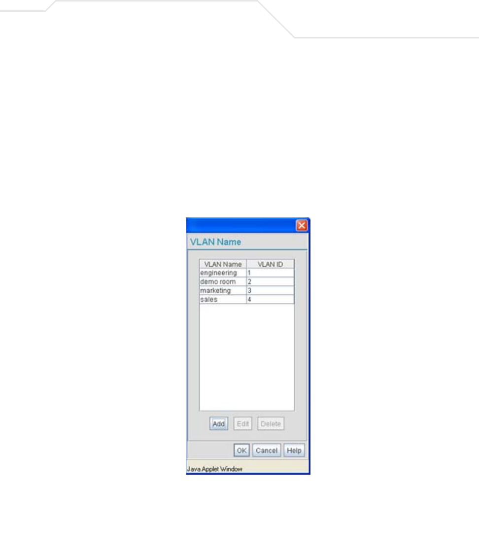
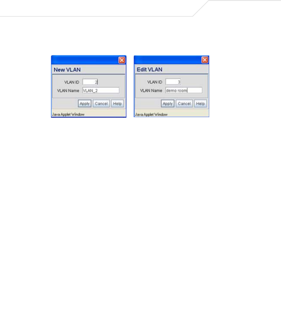
3. Select the VLAN Name button.
The VLAN name screen displays. The first time the screen is launched a default VLAN name
of 1 and a default VLAN ID of 1 display. The VLAN name is auto-generated once the user
assigns a VLAN ID. However, the user has the option of re-assigning a name to the VLAN
using New VLAN and Edit VLAN screens.
AP-51xx Access Point Product Reference Guide
5-6
To create a new VLAN, click the Create button, to edit the properties of an existing VLAN,
click the Edit button.
4. Assign a unique VLAN ID (from 1 to 4095) to each VLAN added or modified.
The VLAN ID associates a frame with a specific VLAN and provides the information the
access point needs to process the frame across the network. Therefore, it may be practical
to assign a name to a VLAN representative or the area or type of network traffic it
represents.
A business may have offices in different locations and want to extend an internal LAN
between the locations. An access point managed infrastructure could provide this
connectivity, but it requires VLAN numbering be managed carefully to avoid conflicts
between two VLANs with the same ID.
5. Define a 32 ASCII character maximum VLAN Name.
Enter a unique name that identifies members of the VLAN. Symbol recommends selecting
the name carefully, as the VLAN name should signify a group of clients with a common set
of requirements independent of their physical location.
6. Click Apply to save the changes to the new or modified VLAN.
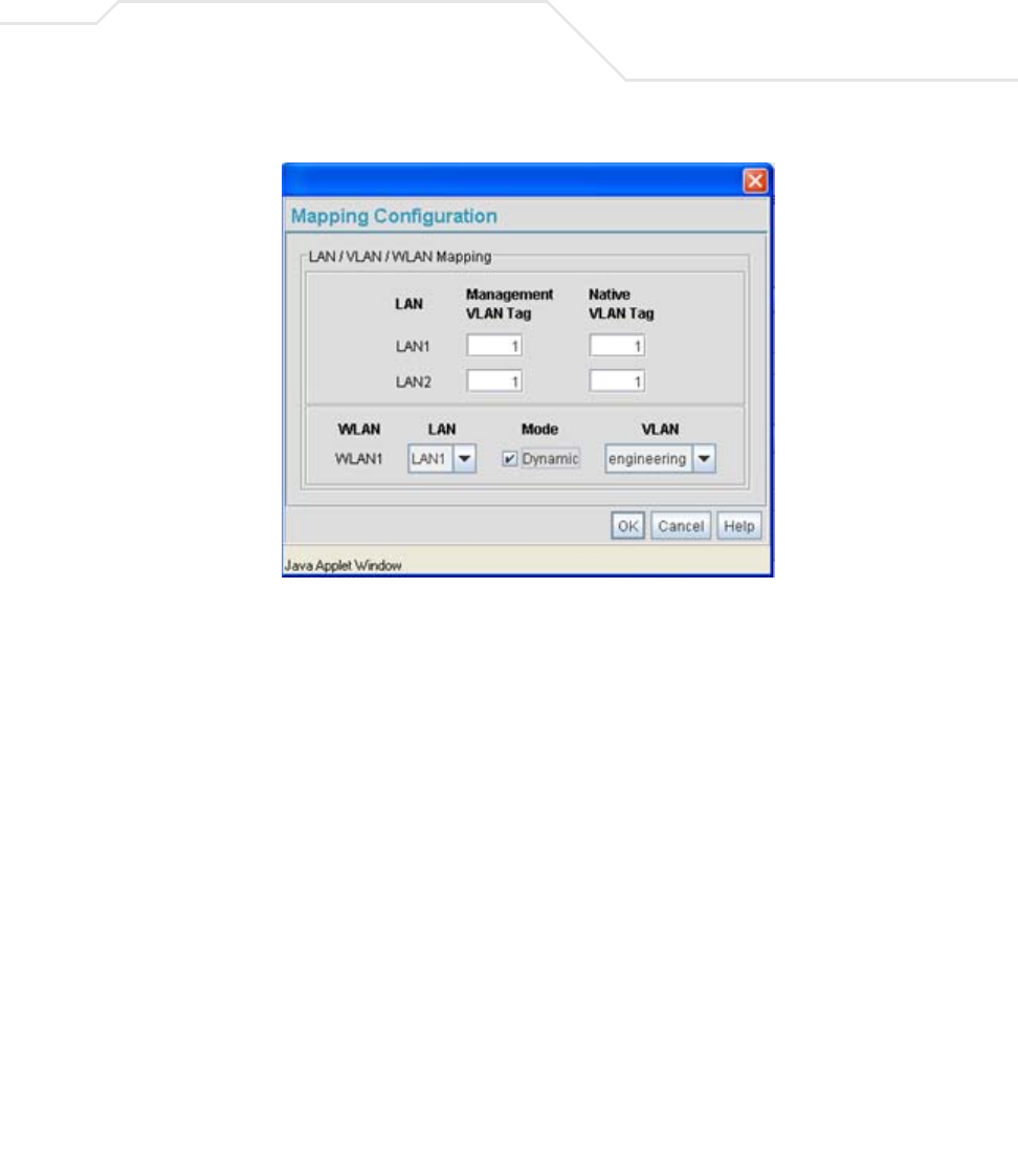
7. From the LAN Configuration screen, click the WLAN Mapping button. The Mapping
Configuration screen displays.
Network Management 5-7
8. Enter a Management VLAN Tag for LAN1 and LAN2.
The Management VLAN uses a default tag value of 1. The Management VLAN is used to
distinguish VLAN traffic flows for the LAN. The trunk port marks the frames with special
tags as they pass between the access point and its destination, these tags help distinguish
data traffic.
Authentication servers (such as Radius and Kerberos) must be on the same Management
VLAN. Additionally, DHCP and BOOTP servers must be on the same Management VLAN as
well.
9. Define a Native VLAN Tag for LAN1 and LAN2.
A trunk port configured with 802.1Q tagging can receive both tagged and untagged traffic.
By default, the access point forwards untagged traffic with the native VLAN configured for
the port. The Native VLAN is VLAN 1 by default. Symbol suggests leaving the Native VLAN
set to 1 as other layer 2 devices also have their Native VLAN set to 1.
10. Use the LAN drop-down menu to map one of the two LANs to the WLAN listed to the left.
With this assignment, the WLAN uses this assigned LAN interface.
11. Select the Dynamic checkboxes (under the Mode column) to configure the VLAN mapping
as a dynamic VLAN.
Using Dynamic VLAN assignments, a VMPS (VLAN Management Policy Server) dynamically
assigns VLAN ports. The access point uses a separate server as a VMPS server. When a

AP-51xx Access Point Product Reference Guide
5-8
frame arrives on the access point, it queries the VMPS for the VLAN assignment based on
the source MAC address of the arriving frame.
If statically mapping VLANs, leave the Dynamic checkbox specific to the target WLAN and
its intended VLAN unselected. The administrator is then required to configure VLAN
memberships manually.
The Dynamic checkbox is enabled only when a WLAN is having EAP security configured.
Otherwise, the checkbox is disabled.
12. Use the VLAN drop-down menu to select the name of the target VLAN to map to the WLAN
listed on the left-hand side of the screen.
Symbol recommends mapping VLANs strategically in order to keep VLANs tied to the
discipline they most closely match. For example, If WLAN1 is comprised of MUs supporting
the sales area, then WLAN1 should be mapped to sales if a sales VLAN has been already
been created.
13. Click Apply to return to the VLAN Name screen. Click OK to return to the LAN screen. Once
at the LAN screen, click Apply to re-apply your changes.
5.1.2 Configuring LAN1 and LAN2 Settings
Both LAN1 and LAN2 have separate sub-screens to configure the DHCP settings used by the LAN1
and LAN2 interfaces. Within each LAN screen is a button to access a sub-screen to configure
advanced DHCP settings for that LAN. For more information, see Configuring Advanced DHCP Server
Settings on page 5-11. Additionally, LAN1 and LAN2 each have separate Type Filter submenu items
used to prevent specific (an potentially unneccesary) frames from being processed, for more
information, see Setting the Type Filter Configuration on page 5-13.
To configure unique settings for either LAN1 or LAN2:
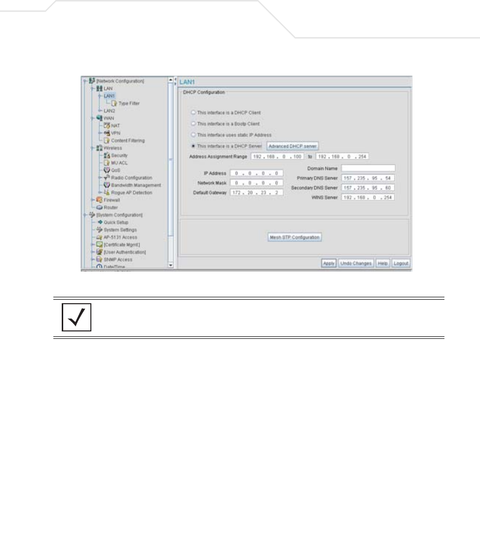
1. Select Network Configuration -> LAN -> LAN1 (or LAN2) from the access point menu
tree.
Network Management 5-9
2. Configure the DHCP Configuration field to define the DHCP settings used for the LAN.
NOTE Symbol recommends the WAN and LAN ports should not both be
configured as DHCP clients.
This interface is a
DHCP Client
Select this button to enable DHCP to set access point network
address information via this LAN1 or LAN2 connection. This is
recommended if the access point resides within a large corporate
network or the Internet Service Provider (ISP) uses DHCP.
DHCP is a protocol that includes mechanisms for IP address
allocation and delivery of host-specific configuration parameters
from a DHCP server to a host. If DHCP Client is selected, the first
DHCP or BOOTP server to respond sets the IP address and network
address values since DHCP and BOOTP are interoperable.
This interface is a
BOOTP Client
Select this button to enable BOOTP to set access point network
address information via this LAN1 or LAN2 connection.
When selected, only BOOTP responses are accepted by the access
point. If both DHCP and BOOTP services are required, do not select
BOOTP Client.

AP-51xx Access Point Product Reference Guide
5-10
This interface uses
static IP Address
Select the This interface uses static IP Address button, and
manually enter static network address information in the areas
provided.
This interface is a
DHCP Server
The access point can be configured to function as a DHCP server
over the LAN1 or LAN2 connection. Select the This interface is a
DHCP Server button and manually enter static network address
information in the areas provided.
Address Assignment
Range
Use the address assignment parameter to specify a range of
numerical (non DNS name) IP addresses reserved for mapping
client MAC addresses to IP addresses. If a manually (static)
mapped IP address is within the IP address range specified, that IP
address could still be assigned to another client. To avoid this,
ensure all statically mapped IP addresses are outside of the IP
address range assigned to the DHCP server.
Advanced DHCP
Server
Click the Advanced DHCP Server button to display a screen used
for generating a list of static MAC to IP address mappings for
reserved clients. A separate screen exists for each of the LANs. For
more information, see Configuring Advanced DHCP Server Settings
on page 5-11.
IP Address The network-assigned numerical (non DNS name) IP address of
the access point.
Network Mask The first two sets of numbers specify the network domain, the next
set specifies the subset of hosts within a larger network. These
values help divide a network into subnetworks and simplify routing
and data transmission. The subnet mask defines the size of the
subnet.
Default Gateway The Default Gateway parameter defines the numerical (non
DNS name) IP address of a router the access point uses on the
Ethernet as its default gateway.
Domain Name Enter the name assigned to the primary DNS server.
Primary DNS Server Enter the Primary DNS numerical (non DNS name) IP address.
Secondary DNS
Server
Symbol recommends entering the numerical IP address of an
additional DNS server (if available), used if the primary DNS server
goes down. A maximum of two DNS servers can be used.

Network Management 5-11
3. Click Apply to save any changes to the LAN1 or LAN2 screen. Navigating away from the
screen without clicking the Apply button results in all changes to the screen being lost if the
prompts are ignored.
4. Click Undo Changes (if necessary) to undo any changes made. Undo Changes reverts the
settings displayed on the LAN1 or LAN2 screen to the last saved configuration.
5. Click Logout to securely exit the access point Symbol Access Point applet. A prompt
displays confirming the logout before the applet is closed.
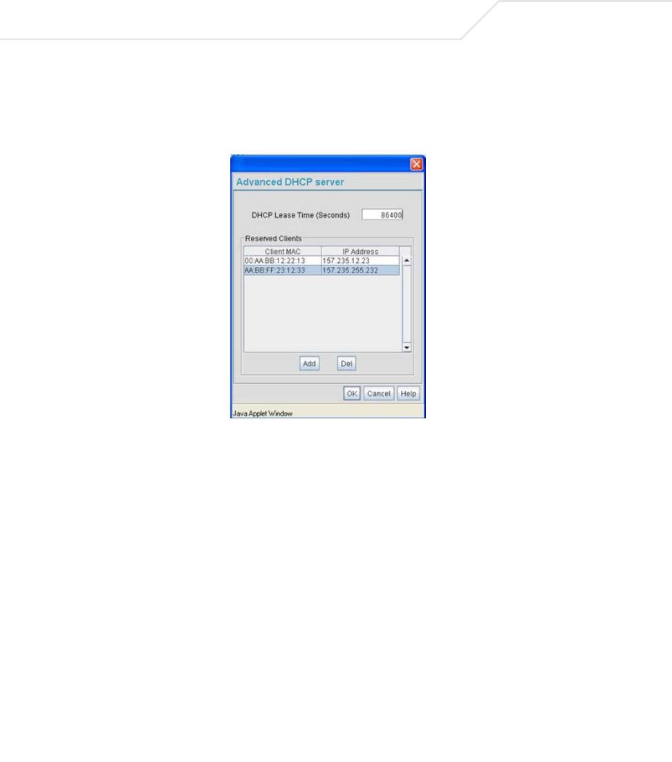
5.1.2.1 Configuring Advanced DHCP Server Settings
Use the Advanced DHCP Server screen to specify (reserve) static (or fixed) IP addresses for specific
devices. Every wireless, 802.11x-standard device has a unique Media Access Control (MAC) address.
This address is the device's hard-coded hardware number (shown on the bottom or back). An example
of a MAC address is 00:A0:F8:45:9B:07.
The DHCP server can grant an IP address for as long as it remains in active use. The lease time is the
number of seconds that an IP address is reserved for re-connection after its last use. Using very short
leases, DHCP can dynamically reconfigure networks in which there are more computers than
available IP addresses. This is useful, for example, in education and customer environments where
MU users change frequently. Use longer leases if there are fewer users.
To generate a list of client MAC address to IP address mappings for the access point:
WINS Server Enter the numerical (non DNS name) IP address of the WINS
server. WINS is a Microsoft NetBIOS name server. Using a WINS
server eliminates the broadcasts needed to resolve computer
names to IP addresses by providing a cache or database of
translations.
Mesh STP
Configuration
Click the Mesh STP Configuration button to define bridge
settings for this specific LAN. Each of the access point’s two LANs
can have a separate mesh configuration. As the Spanning Tree
Protocol (STP) mentions, each mesh network maintains hello,
forward delay and max age timers. These settings can be used as
is using the current default settings, or be modified. However, if
these settings are modified, they need to be configured for the LAN
connecting to the mesh network WLAN.
For information on mesh networking capabilities, see Configuring
Mesh Networking Support on page 9-5. If new to mesh networking
and in need of an overview, see
Mesh Networking Overview on page 9-1.
AP-51xx Access Point Product Reference Guide
5-12
1. Select Network Configuration -> LAN -> LAN1 (or LAN2) from the access point menu
tree.
2. Click the Advanced DHCP Server button from within the LAN1 or LAN2 screen.
3. Specify a lease period in seconds for available IP addresses using the DHCP Lease Time
(Seconds) parameter. An IP address is reserved for re-connection for the length of time you
specify. The default interval is 86400 seconds.
4. Click the Add button to create a new table entry within the Reserved Clients field.
If a statically mapped IP address is within the IP address range in use by the DHCP server,
that IP address may still be assigned to another client. To avoid this, ensure all statically
mapped IP addresses are outside of the IP address range assigned to the DHCP server.
If multiple entries exist within the Reserved Clients field, use the scroll bar to the right of
the window to navigate.
5. Click the Del (delete) button to remove a selected table entry.
6. Click OK to return to the LAN1 or LAN2 page, where the updated settings within the
Advanced DHCP Server screen can be saved by clicking the Apply button.
7. Click Cancel to undo any changes made. Undo Changes reverts the settings displayed to
the last saved configuration.
Network Management 5-13
5.1.2.2 Setting the Type Filter Configuration
Each access point LAN (either LAN1 or LAN2) can keep a list of frame types that it forwards or
discards. The Type Filtering feature prevents specific (a potentially unneccesary) frames from being
processed by the access point in order to improve throughput. These include certain broadcast frames
from devices that consume bandwidth, but are unnecessary to access point operations.
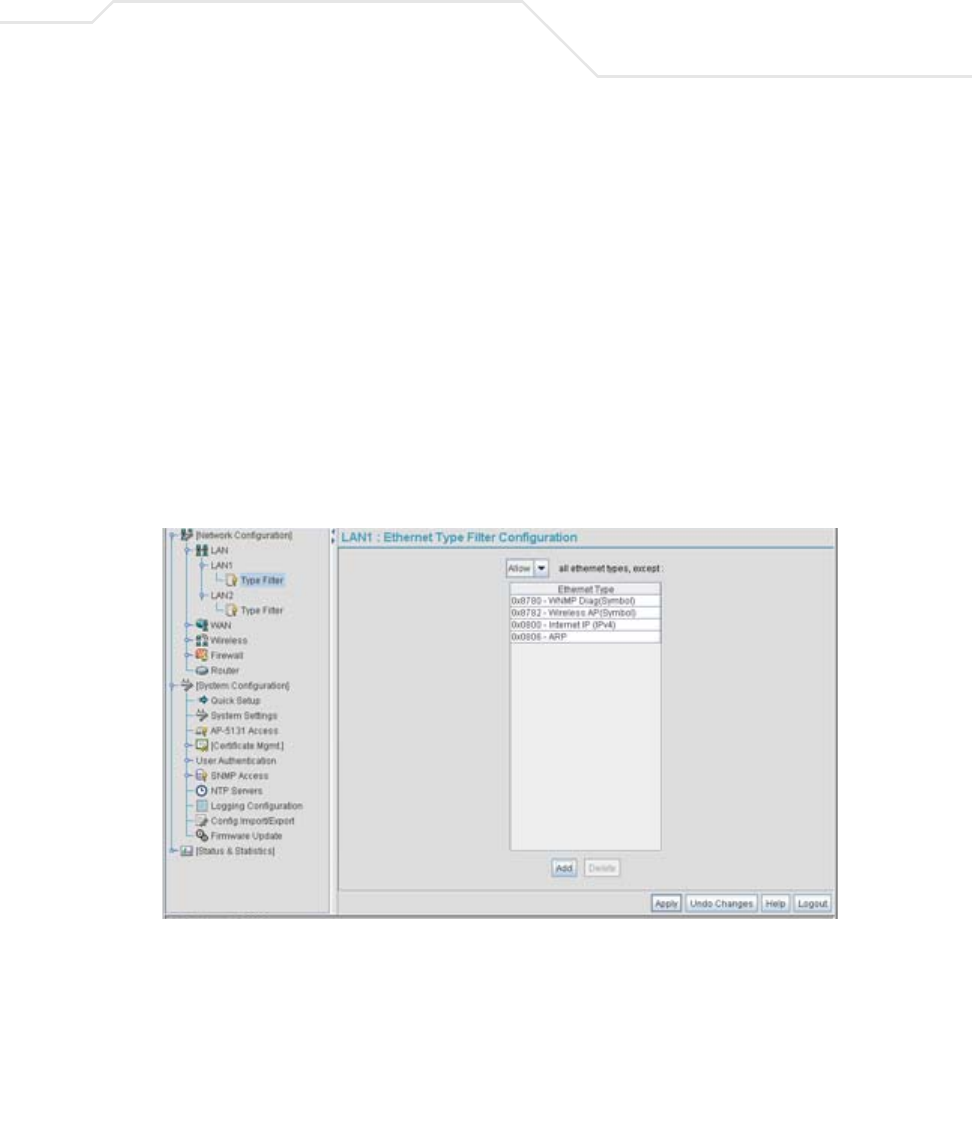
Use the Ethernet Type Filter Configuration screen to build a list of filter types and configure them
as either allowed or denied for use with the this particular LAN.
To configure type filtering on the access point:
1. Select Network Configuration-> LAN -> LAN1 (or LAN2)-> Type Filter from the access
point menu tree.
The Ethernet Type Filter Configuration screen displays for the LAN. No Ethernet types
are displayed (by default) when the screen is first launched.
2. Use the all ethernet types, except drop-down menu to designate whether the Ethernet
Types defined for the LAN are allowed or denied for use by the access point.
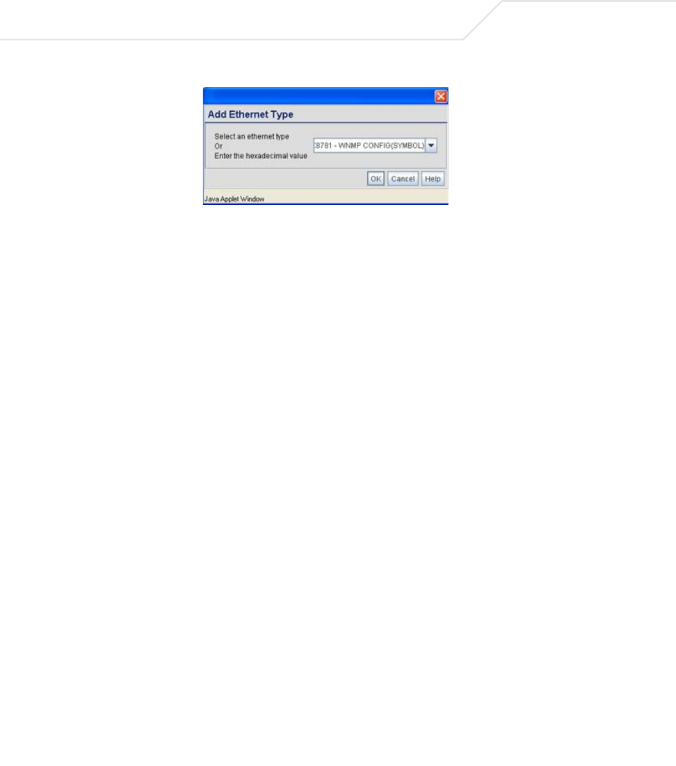
3. To add an Ethernet type, click the Add button.
The Add Ethernet Type screen displays. Use this screen to add one type filter option at a
time, for a list of up to 16 entries.
AP-51xx Access Point Product Reference Guide
5-14
Packet types supported for the type filtering function include 16-bit DIX Ethernet types as
well as Symbol proprietary types. Select an Ethernet type from the drop down menu, or enter
the Ethernet type’s hexadecimal value. Consult with your System Administrator if unsure of
the implication of adding or omitting a type from the list for either LAN1 or LAN2.
4. To optionally delete a type filtering selection from the list, highlight the packet type and click
the Delete button.
5. Click Apply to save any changes to the LAN1 or LAN2 Ethernet Type Filter Configuration
screen. Navigating away from the screen without clicking Apply results in all changes to the
screens being lost.
6. Click Cancel to securely exit the LAN1 or LAN2 Ethernet Type Filter Configuration screen
without saving your changes.
7. Click Logout to securely exit the access point Symbol Access Point applet. A prompt
displays confirming the logout before the applet is closed.
5.2 Configuring WAN Settings
A Wide Area Network (WAN) is a widely dispersed telecommunications network. The access point
includes one WAN port. The access point WAN port has its own MAC address. In a corporate
environment, the WAN port might connect to a larger corporate network. For a small business, the
WAN port might connect to a DSL or cable modem to access the Internet.
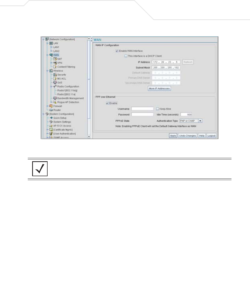
Use the WAN screen to set the WAN IP configuration and Point-to-Point Protocol over Ethernet
(PPPoE) parameters.
To configure WAN settings for the access point:
1. Select Network Configuration -> WAN from the access point menu tree.
Network Management 5-15
2. Refer to the WAN IP Configuration field to enable the WAN interface, and set network
address information for the WAN connection.
NOTE Symbol recommends that the WAN and LAN ports should not both be
configured as DHCP clients.
Enable WAN Interface Select the Enable WAN Interface checkbox to enable a
connection between the access point and a larger network or
outside world through the WAN port.
Disable this option to effectively isolate the access point’s WAN.
No connections to a larger network or the Internet are possible.
MUs cannot communicate beyond the LAN.

AP-51xx Access Point Product Reference Guide
5-16
This interface is a
DHCP Client
This checkbox enables DHCP for the access point WAN
connection. This is useful, if the larger corporate network or
Internet Service Provider (ISP) uses DHCP.
DHCP is a protocol that includes mechanisms for IP address
allocation and delivery of host-specific configuration parameters
from a DHCP server to a host. Some of these parameters are IP
address, network mask, and gateway.
If DHCP client mode is enabled, the other WAN IP configuration
parameters are grayed out.
IP Address Specify a numerical (non DNS name) IP address for the access
point’s WAN connection. This address defines the AP's presence
on a larger network or on the Internet.
Obtain a static (dedicated) IP address from the ISP or network
administrator. An IP address uses a series of four numbers
expressed in dot notation, for example, 190.188.12.1.
Subnet Mask Specify a subnet mask for the access point’s WAN connection.
This number is available from the ISP for a DSL or cable-modem
connection, or from an administrator if the access point connects
to a larger network.
A subnet mask uses a series of four numbers expressed in dot
notation (similar to an IP address). For example, 255.255.255.0 is a
valid subnet mask.
Default Gateway Specify the gateway address for the access point’s WAN
connection. The ISP or a network administrator provides this
address.
Primary DNS Server Specify the address of a primary Domain Name System (DNS)
server. The ISP or a network administrator provides this address.
A DNS server translates a domain name (for example,
www.symboltech.com) into an IP address that networks can use.
Secondary DNS
Server
Specify the address of a secondary DNS server if one is used. A
secondary address is recommended if the primary DNS server goes
down.

Network Management 5-17
3. Configure the PPP over Ethernet field to enable high speed dial-up connections to the
access point WAN port.
More IP Addresses Click the More IP Addresses button to specify additional static IP
addresses for the access point. Additional IP addresses are
required when users within the WAN need dedicated IP addresses,
or when servers need to be accessed (addressed) by the outside
world. The More IP Addresses screen allows the administrator to
enter up to seven additional WAN IP addresses for the access
point WAN. Only numeric, non-DNS names can be used.
If PPP over Ethernet is enabled from within the WAN screen, the
VPN WAN IP Configuration portion of the More IP Addresses
screen is enabled. Enter the IP address and subnet mask used to
provide the PPPoE connection over the access point’s WAN port.
Ensure the IP address is a numerical (non DNS) name.
Refresh Click the Refresh button to update the network address
information displayed within the WAN IP Configuration field.
Enable Use the checkbox to enable Point-to-Point over Ethernet (PPPoE) for
a high-speed connection that supports this protocol. Most DSL
providers are currently using or deploying this protocol.
PPPoE is a data-link protocol for dialup connections. PPPoE allows
a host PC to use a broadband modem (DSL) for access to high-
speed data networks.
Username Specify a username entered when connecting to the ISP. When the
Internet session begins, the ISP authenticates the username.
Password Specify a password entered when connecting to the ISP. When the
Internet session starts, the ISP authenticates the password.
PPPoE State Displays the current connection state of the PPPoE client. When a
PPPoE connection is established, the status displays Connected.
When no PPPoE connection is active, the status displays
Disconnected.

AP-51xx Access Point Product Reference Guide
5-18
4. Click Apply to save any changes to the WAN screen. Navigating away from the screen
without clicking the Apply button results in all changes to the screen being lost.
5. Click Undo Changes (if necessary) to undo any changes made. Undo Changes reverts the
settings displayed on the WAN screen to the last saved configuration.
Keep-Alive Select the Keep-Alive checkbox to maintain the access point
WAN connection indefinitely (no timeout interval). Some ISPs
terminate inactive connections. Enabling Keep-Alive keeps the
access point WAN connection active, even when there is no
traffic. If the ISP drops the connection after an idle period, the
access point automatically re-establishes the connection to the
ISP. Enabling Keep-Alive mode disables (grays out) the Idle Time
field.
Idle Time (seconds) Specify an idle time in seconds to limit how long the access
point’s WAN connection remains active after outbound and
inbound traffic is not detected. The Idle Time field is grayed out if
Keep-Alive is enabled.
Authentication Type Use the Authentication Type menu to specify the authentication
protocol(s) for the WAN connection. Choices include None, PAP or
CHAP, PAP, or CHAP.
Password Authentication Protocol (PAP) and Challenge Handshake
Authentication Protocol (CHAP) are competing identify-verification
methods.
PAP sends a username and password over a network to a server
that compares the username and password to a table of authorized
users. If the username and password are matched in the table,
server access is authorized. WatchGuard products do not support
the PAP protocol because the username and password are sent as
clear text that a hacker can read.
CHAP uses secret information and mathematical algorithms to
send a derived numeric value for login. The login server knows the
secret information and performs the same mathematical
operations to derive a numeric value. If the results match, server
access is authorized. After login, one of the numbers in the
mathematical operation is changed to secure the connection. This
prevents any intruder from trying to copy a valid authentication
session and replaying it later to log in.
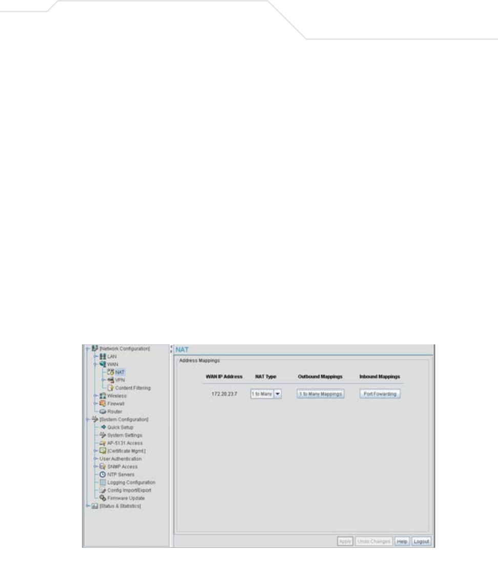
Network Management 5-19
6. Click Logout to securely exit the access point Symbol Access Point applet. A prompt
displays confirming the logout before the applet is closed.
5.2.1 Configuring Network Address Translation (NAT) Settings
Network Address Translation (NAT) converts an IP address in one network to a different IP address or
set of IP addresses in another network. The access point router maps its local (inside) network
addresses to WAN (outside) IP addresses, and translates the WAN IP addresses on incoming packets
to local IP addresses. NAT is useful because it allows the authentication of incoming and outgoing
requests, and minimizes the number of WAN IP addresses needed when a range of local IP addresses
is mapped to each WAN IP address. NAT can be applied in one of two ways:
• One-to-one mapping with a private side IP address
The private side IP address can belong to any of the private side subnets.
• One-to-many mapping with a configurable range of private side IP addresses
Ranges can be specified from each of the private side subnets.
Use the NAT screen to configure IP address mappings. To configure IP address mappings for the
access point:
1. Select Network Configuration -> WAN -> NAT from the access point menu tree.

AP-51xx Access Point Product Reference Guide
5-20
2. Configure the Address Mappings field to generate a WAN IP address, define the NAT type
and set outbound/inbound NAT mappings.
3. Click Apply to save any changes to the NAT screen. Navigating away from the screen
without clicking the Apply button results in all changes to the screens being lost.
4. Click Undo Changes (if necessary) to undo any changes made. Undo Changes reverts the
settings displayed on the NAT screen to the last saved configuration.
WAN IP Address The WAN IP addresses on the NAT screen are dynamically
generated from address settings applied on the WAN screen.
NAT Type Specify the NAT Type as 1 to 1 to map a WAN IP address to a single
host (local) IP address. 1 to 1 mapping is useful when users need
dedicated addresses, and for public-facing servers connected to
the access point.
Set the NAT Type as 1 to Many to map a WAN IP address to
multiple local IP addresses. This displays the 1 to Many Mappings
button in the adjacent Outbound Mappings field. This button
displays a screen for mapping the LAN IP addresses that are
associated with each subnet.
Define the NAT Type as none when routable IP addresses are used
on the internal network.
Outbound Mappings When 1 to 1 NAT is selected, a single IP address can be entered in
the Outbound Mappings area. This address provides a 1 to 1
mapping of the WAN IP address to the specified IP address.
When 1 to Many is selected as the NAT Type, the Outbound
Mappings area displays a 1 to Many Mappings button. Click the
button to select the LAN1 or LAN2 IP address used to set the
outbound IP address or select none to exclude the IP address.
If none is selected as the NAT Type, The Outbound Mappings area
is blank.
Inbound Mappings When 1 to 1 or 1 to Many is selected, the Inbound Mappings
option displays a Port Forwarding button.
Port Forwarding Click the Port Forwarding button to display a screen of port
forwarding parameters for inbound traffic from the associated
WAN IP address. for information on configuring port forwarding,
see Configuring Port Forwarding on page 5-21.
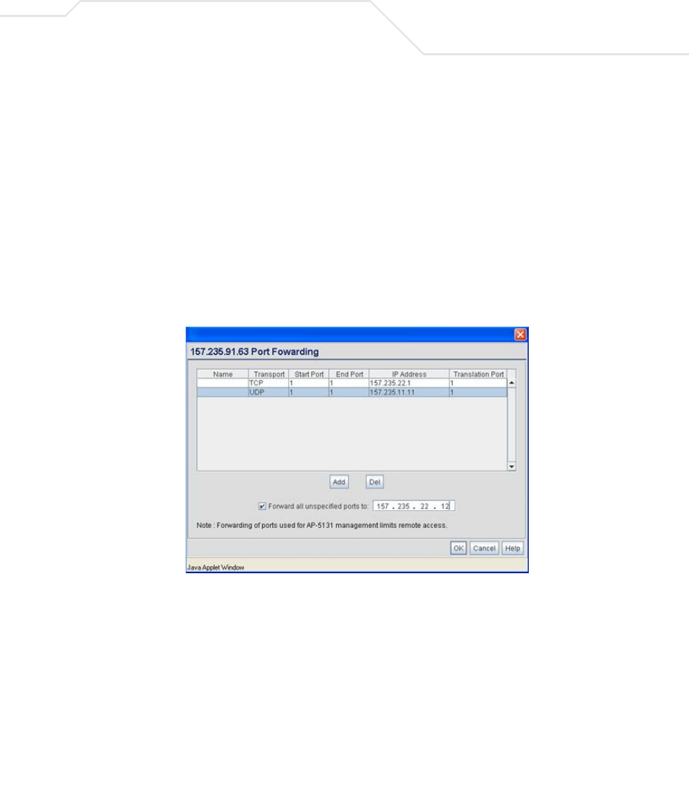
Network Management 5-21
5. Click Logout to securely exit the access point Symbol Access Point applet. A prompt
displays confirming the logout before the applet is closed.
5.2.1.1 Configuring Port Forwarding
Use the Port Forwarding screen to configure port forwarding parameters for inbound traffic from
the associated WAN IP address.
To configure port forwarding for the access point:
1. Select Network Configuration -> WAN -> NAT from the access point menu tree.
2. Select 1 to 1 or 1 to Many from the NAT Type drop-down menu.
3. Click on the Port Forwarding button within the Inbound Mappings area.
4. Configure the Port Forwarding screen to modify the following:
Add Click Add to create a local map that includes the name, transport
protocol, start port, end port, IP address and Translation Port for
incoming packets.
Delete Click Delete to remove a selected local map entry.
Name Enter a name for the service being forwarded. The name can be any
alphanumeric string and is used for identification of the service.

AP-51xx Access Point Product Reference Guide
5-22
5. Click Ok to return to the NAT screen. Within the NAT screen, click Apply to save any
changes made on the Port Forwarding screen.
6. Click Cancel to undo any changes made on Port Forwarding screen. This reverts all settings
for the Port Forwarding screen to the last saved configuration.
5.3 Enabling Wireless LANs (WLANs)
A Wireless Local Area Network (WLAN) is a data-communications system that flexibly extends the
functionalities of a wired LAN. A WLAN does not require lining up devices for line-of-sight
transmission, and are thus, desirable. Within the WLAN, roaming users can be handed off from one
access point to another like a cellular phone system. WLANs can therefore be configured around the
needs of specific groups of users, even when they are not in physical proximity.
Use the access point’s Wireless Configuration screen to create new WLANs, edit the properties of
existing WLANs or delete a WLAN to create space for a new WLAN. Sixteen WLANs are available
on the access point (regardless of single or dual-radio model).
Transport Use the Transport pull-down menu to specify the transport
protocol used in this service. The choices are ALL, TCP, UDP, ICMP,
AH, ESP, and GRE.
Start Port and End Port Enter the port or ports used by the port forwarding service. To
specify a single port, enter the port number in the Start Port area.
To specify a range of ports, use both the Start Port and End Port
options to enter the port numbers. For example, enter 110 in the
Start Port field and 115 in the End Port field.
IP Address Enter the numerical (non DNS name) IP address to which the
specified service is forwarded. This address must be within the
specified NAT range for the associated WAN IP address.
Translation Port Specify the port number used to translate data for the service being
forwarded.
Forward all
unspecified ports to
Use the Forward all unspecified ports to checkbox to enable
port forwarding for incoming packets with unspecified ports. In the
adjacent area, enter a target forwarding IP address for incoming
packets. This number must be within the specified NAT range for
the associated WAN IP address.

Network Management 5-23
To configure WLANs on the access point:
1. Select Network Configuration -> Wireless from the access point menu tree.
If a WLAN is defined, that WLAN displays within the Wireless Configuration screen. When
the access point is first booted, WLAN1 exists as a default WLAN available immediately for
connection.
2. Refer to the information within the Wireless Configuration screen to view the name, ESSID,
access point radio designation, VLAN ID and security policy of existing WLANs.
WLAN Name The Name field displays the name of each WLAN that has been
defined. The WLAN names can be modified within individual
WLAN configuration screens. See Creating/Editing Individual
WLANs on page 5-24 to change the name of a WLAN.
ESSID Displays the Extended Services Set Identification (ESSID)
associated with each WLAN. The ESSID can be modified within
individual WLAN configuration screens. See Creating/Editing
Individual WLANs on page 5-24 to change the ESSID of a specific
WLAN.
Radio The Radio field displays the name of the access point radio the
WLAN is mapped to (either the 802.11a radio or the 802.11b/g
radio). To change the radio designation for a specific WLAN, see
Creating/Editing Individual WLANs on page 5-24.

AP-51xx Access Point Product Reference Guide
5-24
3. Click the Create button (if necessary) to launch the New WLAN screen. Use the New
WLAN screen to define the properties of a new WLAN that would display and be selectable
within the Wireless Configuration screen. For additional information, see
Creating/Editing Individual WLANs on page 5-24.
4. Click the Edit button (if necessary) to launch the Edit WLAN screen. Use the Edit WLAN
screen to revise the properties of an existing WLAN that would continue display and be
selectable within the Wireless Configuration screen. For additional information, see
Creating/Editing Individual WLANs on page 5-24.
5. Consider using the Delete button to remove an existing WLAN if it has become outdated
and is no longer required or if you are coming close the maximum 16 WLANs available per
access point.
6. Click Logout to securely exit the access point Symbol Access Point applet. A prompt
displays confirming the logout before the applet is closed.
5.3.1 Creating/Editing Individual WLANs
If the WLANs displayed within the Wireless Configuration screen do not satisfy your network
requirements, you can either create a new WLAN or edit the properties of an existing WLAN.
VLAN The VLAN field displays the specific VLAN the target WLAN is
mapped to. For information on VLAN configuration for the WLAN,
see Configuring VLAN Support on page 5-4.
Security Policy The Security Policy field displays the security profile configured
for the target WLAN. For information on configuring security for a
WLAN, see Enabling Authentication and Encryption Schemes on
page 6-5.
QoS Policy The QoS Policy field displays the quality of service currently
defined for the WLAN. This policy outlines which data types
receive priority for the user base comprising the WLAN. For
information on QoS configuration for the WLAN, see
Setting the WLAN Quality of Service (QoS) Policy on page 5-33.
NOTE Before editing the properties of an existing WLAN, ensure it is not being
used by an access point radio, or is a WLAN that is needed in its current
configuration. Once updated, the previous configuration is not available
unless saved.
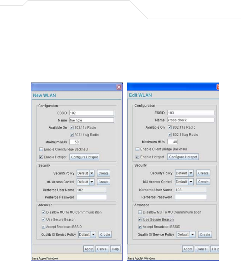
Network Management 5-25
Use the New WLAN and Edit WLAN screens as required to create/modify a WLAN. To create a new
WLAN or edit the properties of an existing WLAN:
1. Select Network Configuration -> Wireless from the access point menu tree.
The Wireless Configuration screen displays.
2. Click the Create button to configure a new WLAN, or highlight a WLAN and click the Edit
button to modify an existing WLAN. Either the New WLAN or Edit WLAN screen displays.
3. Set the parameters in the Configuration field as required for the WLAN.

AP-51xx Access Point Product Reference Guide
5-26
ESSID Enter the Extended Services Set Identification (ESSID) associated
with the WLAN. The WLAN name is auto-generated using the
ESSID until changed by the user. The maximum number of
characters that can be used for the ESSID is 32.
Name Define or revise the name for the WLAN. The name should be
logical representation of WLAN coverage area (engineering,
marketing etc.). The maximum number of characters that can be
used for the name is 31.
Available On Use the Available On checkboxes to define whether the WLAN
you are creating or editing is available to clients on either the
802.11a or 802.11b/g radio (or both radios). The Available On
checkbox should only be selected for a mesh WLAN if this target
access point is to be configured as a base bridge or repeater (base
and client bridge) on the radio. If the radio for the WLAN is to be
defined as a client bridge only, the Available On checkbox should
not be selected. For more information on defining a WLAN for
mesh support, see
Configuring a WLAN for Mesh Networking Support on page 9-7.
Max MUs Use the Max MUs field to define the number of MUs permitted to
interoperate within the new or revised WLAN. The maximum (and
default) is 127. However, each access point can only support a
maximum 127 MUs spanned across its 16 available WLANs. If you
intend to define numerous WLANs, ensure each is using a portion
of the 127 available MUs and the sum of the supported MUs across
all WLANs does not exceed 127.
Enable Client Bridge
Backhaul
Select the Enable Client Bridge Backhaul checkbox to make the
WLAN available in the WLAN drop-down menu within the Radio
Configuration screen. This checkbox can be ignored for WLANs
not supporting mesh networking, to purposely exclude them from
the list of WLANs available in the Radio Configuration page
selected specifically for mesh networking support. Only WLANs
defined for mesh networking support should have this checkbox
selected.
Network Management 5-27
4. Configure the Security field as required to set the data protection requirements for the
WLAN.
Enable Hotspot Select the Enable Hotspot checkbox to allow this WLAN (whether
it be a new or existing WLAN) to be configured for hotspot support.
Clicking the Configure Hotspot button launches a screen wherein
the parameters of the hotspot can be defined. For information on
configuring a target WLAN for hotspot support, see Configuring
WLAN Hotspot Support on page 5-39. For an overview of what a
hotspot is and what it can provide your wireless network, see
Hotspot Support on page 1-4.
CAUTION A WLAN cannot be enabled for both mesh and hotspot support at the
same time. Only one of these two options can be enabled at one time,
as the GUI and CLI will prevent both from being enabled.
NOTE If 802.11a is selected as the radio used for the WLAN, the WLAN cannot
use a Kerberos supported security policy.
NOTE A WLAN configured to support Mesh should not have a Kerberos or
802.1x EAP security policy defined for it, as these two authentication
schemes are not supported within a Mesh network.
Security Policy Use the scroll down Security Policies menu to select the security
scheme best suited for the new or revised WLAN. Click the Create
button to jump to the New Security Policy screen where a new
policy can be created to suit the needs of the WLAN. For more
information, see Configuring WLAN Security Policies on page 5-29.
MU Access Control Select an ACL policy suiting the WLAN‘s MU introperability
requirements from the drop-down menu. If the existing ACL
policies do not satisfy the requirements of the WLAN, a new ACL
policy can be created by pressing the Create button. For more
information, see
Configuring a WLAN Access Control List (ACL) on page 5-30.
Kerberos User Name Displays the read-only Kerboros User Name used to associate the
wireless client. This value is the ESSID of the access point.
!

AP-51xx Access Point Product Reference Guide
5-28
5. Configure the Advanced field as required to set MU interoperability permissions, secure
beacon transmissions, broadcast ESSID acceptance and Quality of Service (QoS) policies.
Kerberos Password Enter a Kerberos password if Kerberos has been selected as the
security scheme from within the Security Policies field. The field
is grayed out if Kerberos has not been selected for the WLAN. For
information on configuring Kerberos, see
Configuring Kerberos Authentication on page 6-9.
Disallow MU to MU
Communication
The MU-MU Disallow feature prohibits MUs from communicating
with each other even if they are on different WLANs, assuming one
of the WLAN’s is configured to disallow MU-MU communication.
Therefore, if an MU’s WLAN is configured for MU-MU disallow, it
will not be able to communicate with any other MUs connected to
this access point.
Use Secure Beacon Select the Use Secure Beacon checkbox to not transmit the
access point’s ESSID. If a hacker tries to find an ESSID via an MU,
the ESSID does not display since the ESSID is not in the beacon.
Symbol recommends keeping the option enabled to reduce the
likelihood of hacking into the WLAN.
Accept Broadcast
ESSID
Select the Accept Broadcast ESSID checkbox to associate an
MU that has a blank ESSID (regardless of which ESSID the access
point is currently using). Sites with heightened security
requirements may want to leave the checkbox unselected and
configure each MU with an ESSID. The default is unselected, thus
not allowing the acceptance of broadcast ESSIDs.
Quality of Service
Policy
If QoS policies are undefined (none), select the Create button to
launch the New QoS Policy screen. Use this screen to create a
QoS policy, wherein data traffic for the new or revised WLAN can
be prioritized to best suit the MU transmissions within that WLAN.
For more information, see
Setting the WLAN Quality of Service (QoS) Policy on page 5-33.
CAUTION When using the access point’s hotspot functionality, ensure MUs are
re-authenticated when changes are made to the characteristics of a
hotspot enabled WLAN, as MUs within the WLAN will be dropped
from device association.
!
Network Management 5-29
6. Click Apply to save any changes to the WLAN screen. Navigating away from the screen
without clicking Apply results in all changes to the screens being lost.
7. Click Cancel to securely exit the New WLAN or Edit WLAN screen and return to the
Wireless Configuration screen.
5.3.1.1 Configuring WLAN Security Policies
As WLANs are being defined for an access point, a security policy can be created or an existing policy
edited (using the Create or Edit buttons within the Security Configuration screen) to best serve the
security requirements of the WLAN. Once new policies are defined, they are available within the
New WLAN or Edit WLAN screens and can be mapped to any WLAN. A single security policy can
be used by more than one WLAN if its logical to do so. For example, there may be two or more WLANs
within close proximity of each other requiring the same data protection scheme.
To create a new security policy or modify an existing policy:
1. Select Network Configuration -> Wireless -> Security from the access point menu tree.
The Security Configuration screen appears with existing policies and their attributes
displayed.
Configuring a WLAN security scheme with a discussion of all the authentication and
encryption options available is beyond the scope of this chapter. See Chapter 6, Configuring
Access Point Security on page 6-1 for more details on configuring access point security.
For detailed information on the authentication and encryption options available to the
access point and how to configure them, see to Configuring Security Options on page 6-2
and locate the section that describes your intended security scheme.
NOTE When the access point is first launched, a single security policy (default)
is available and mapped to WLAN 1. It is anticipated numerous additional
security policies will be created as the list of WLANs grows.
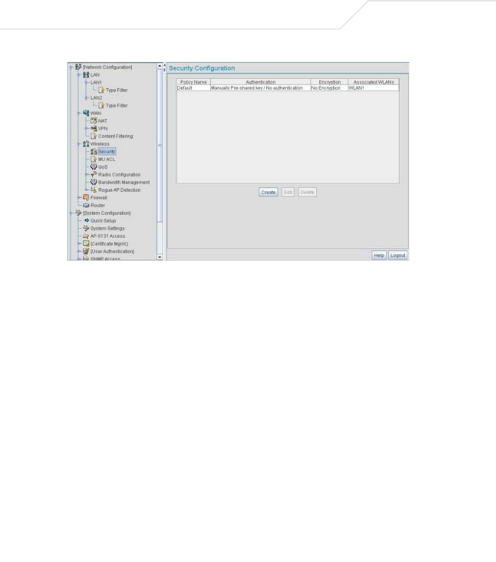
AP-51xx Access Point Product Reference Guide
5-30
2. Click Logout to exit the Security Configuration screen.
5.3.1.2 Configuring a WLAN Access Control List (ACL)
An Access Control Lists (ACL) affords a system administrator the ability to grant or restrict MU access
by specifying a MU MAC address or range of MAC addresses to either include or exclude from access
point connectivity. Use the Mobile Unit Access Control List Configuration screen to create new
ACL policies (using the New MU ACL Policy sub-screen) or edit existing policies (using the Edit MU
ACL Policy sub-screen). Once new policies are defined, they are available for use within the New
WLAN or Edit WLAN screens to assign to specific WLANs based on MU interoperability
requirements.
Symbol recommends using the New MU ACL Policy or Edit MU ACL Policy screens strategically to
name and configure ACL policies meeting the requirements of the particular WLANs they may map
to. However, be careful not to name policies after specific WLANs, as individual ACL policies can be
used by more than one WLAN. For detailed information on assigning ACL policies to specific WLANs,
see Creating/Editing Individual WLANs on page 5-24.
To create or edit ACL policies for WLANs:
1. Select Network Configuration -> Wireless -> MU ACL from the access point menu tree.
The Mobile Unit Access Control List Configuration screen displays with existing ACL
policies and their current WLAN (if mapped to a WLAN).
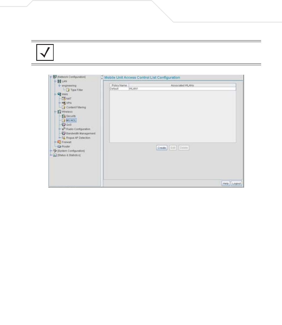
Network Management 5-31
2. Click the Create button to configure a new ACL policy, or select a policy and click the Edit
button to modify an existing ACL policy. The access point supports a maximum of 16 MU ACL
policies.
NOTE When the access point is first launched, a single ACL policy (default) is
available and mapped to WLAN 1. It is anticipated numerous additional
ACL policies will be created as the list of WLANs grows.
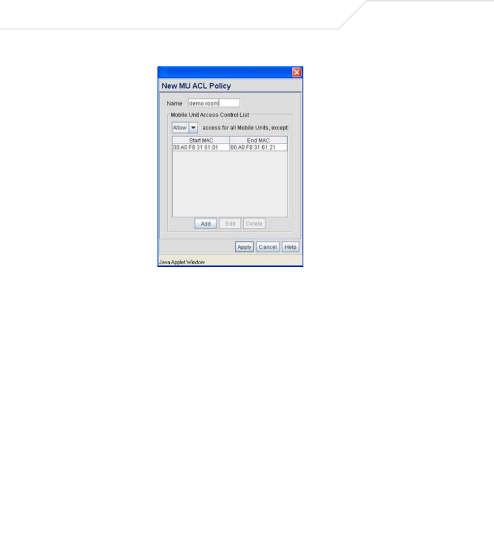
AP-51xx Access Point Product Reference Guide
5-32
Either the New MU ACL Policy or Edit MU ACL Policy screens display.
3. Assign a name to the new or edited ACL policy that represents an inclusion or exclusion
policy specific to a particular type of MU traffic you may want to use with a single or group
of WLANs. More than one WLAN can use the same ACL policy.
4. Configure the parameters within the Mobile Unit Access Control List field to allow or
deny MU access to the access point.
The MU adoption list identifies MUs by their MAC address. The MAC address is the MU's
unique Media Access Control number printed on the device (for example, 00:09:5B:45:9B:07)
by the manufacturer. A maximum of 200 MU MAC addresses can be added to the New/Edit
MU ACL Policy screen.
Access for the listed
Mobile Units
Use the drop-down list to select Allow or Deny. This rule applies
to the MUs listed in the table. For example, if the adoption rule is
to Allow, access is granted for all MUs except those listed in the
table.
Add Click the Add button to create a new entry using only the Start
MAC column to specify a MAC address, or uses both the Start
MAC and End MAC columns to specify a range of MAC addresses.
Delete Click the Delete button to remove a selected list entry.

Network Management 5-33
5. Click Apply to save any changes to the New MU ACL Policy or Edit MU ACL Policy screen
and return to the Mobile Unit Access Control List Configuration screen. Navigating away
from the screen without clicking Apply results in all changes to the screens being lost.
6. Click Cancel to securely exit the New MU ACL Policy or Edit MU ACL Policy screen and
return to the Mobile Unit Access Control List Configuration screen.
7. Click Logout within the Mobile Unit Access Control List Configuration screen to securely
exit the access point Symbol Access Point applet. A prompt displays confirming the logout
before the applet is closed.
5.3.1.3 Setting the WLAN Quality of Service (QoS) Policy
The access point can keep a list of QoS policies that can be used from the New WLAN or Edit
WLAN screens to map to individual WLANs. Use the Quality of Service Configuration screen to
configure WMM policies that can improve the user experience for audio, video and voice applications
by shortening the time between packet transmissions for higher priority (multimedia) traffic.
Use the Quality of Service Configuration screen to define the QoS policies for advanced network
traffic management and multimedia applications support. If the existing QoS policies are insufficient,
a new policy can be created or an existing policy can be modified using the New QoS Policy or Edit
QoS Policy screens. Once new policies are defined, they are available for use within the New
WLAN or Edit WLAN screens to assign to specific WLANs based on MU interoperability
requirements.
Symbol recommends using the New QoS Policy and Edit QoS Policy screens strategically to name and
configure QoS policies meeting the requirements of the particular WLANs they may map to. However,
be careful not to name policies after specific WLANs, as individual QoS policies can be used by more
than one WLAN. For detailed information on assigning QoS policies to specific WLANs, see
Creating/Editing Individual WLANs on page 5-24.
To configure QoS policies:
1. Select Network Configuration -> Wireless -> QoS from the access point menu tree.
The Quality of Service Configuration screen displays with existing QoS policies and their
current WLAN (if mapped to a WLAN).
NOTE When the access point is first launched, a single QoS policy (default) is
available and mapped to WLAN 1. It is anticipated additional QoS policies
will be created as the list of WLANs grows.
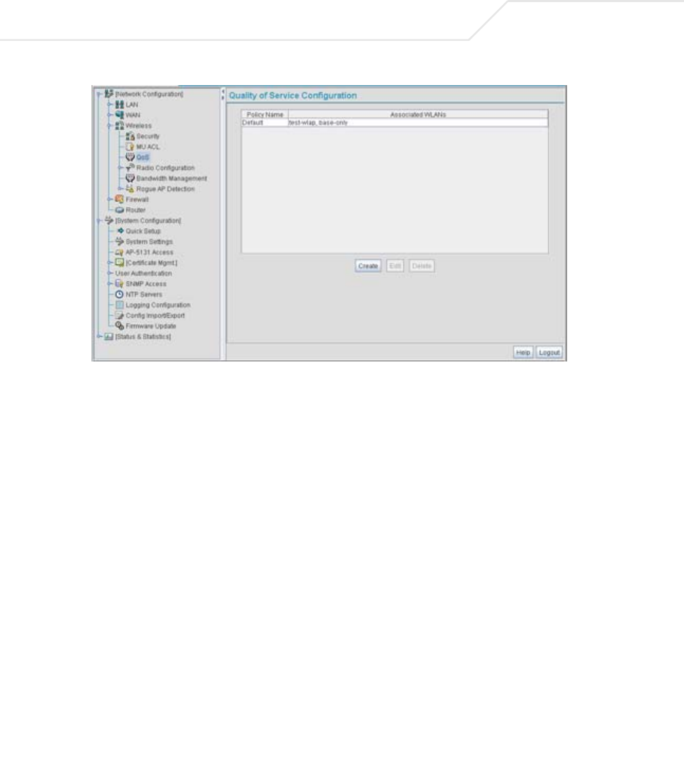
AP-51xx Access Point Product Reference Guide
5-34
2. Click the Create button to configure a new QoS policy, or select a policy and click the Edit
button to modify an existing QoS policy. The access point supports a maximum of 16 QoS
policies.
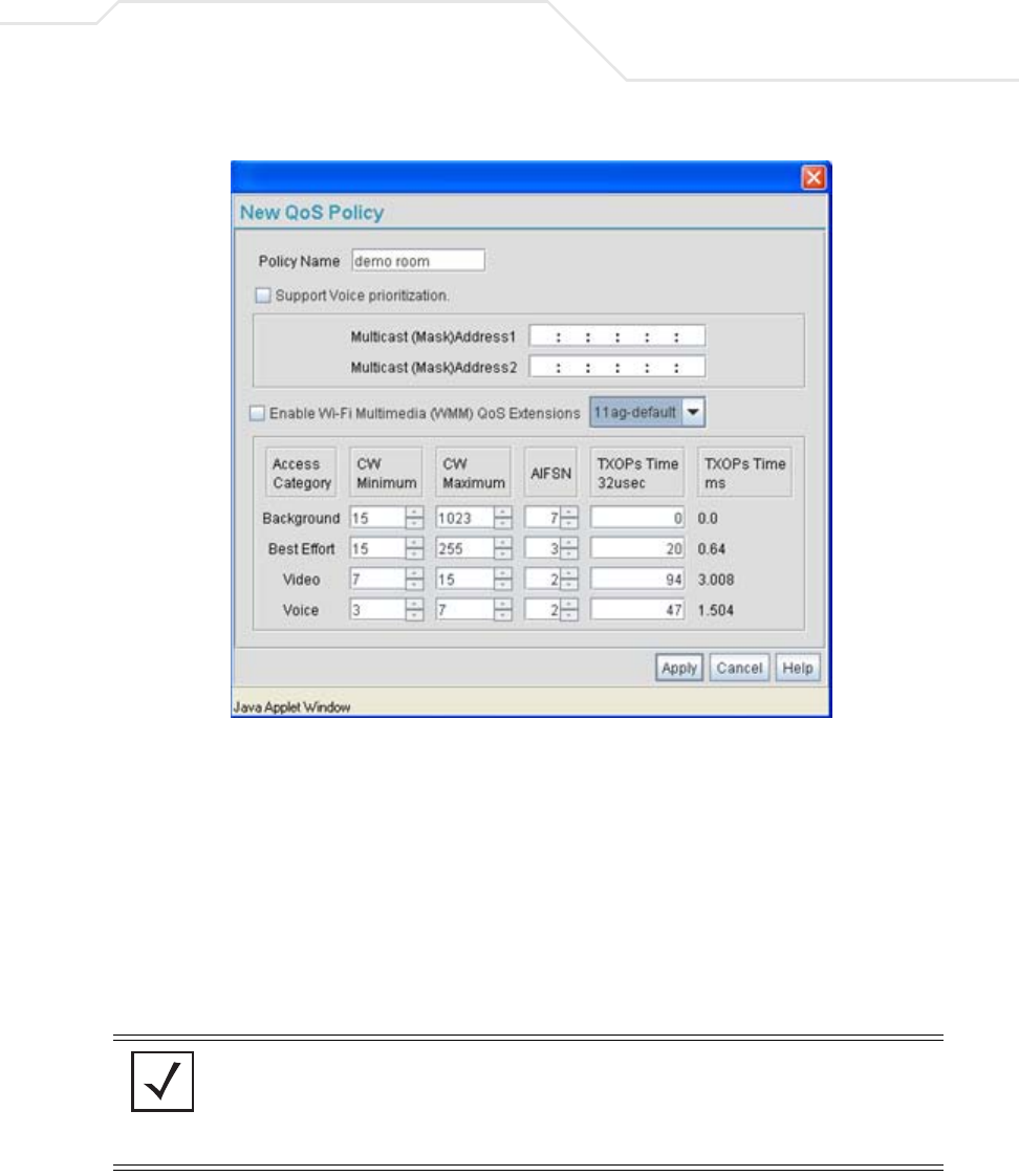
Network Management 5-35
3. Assign a name to the new or edited QoS policy that makes sense to the access point traffic
receiving priority. More than one WLAN can use the same QoS policy.
4. Select the Support Voice prioritization checkbox to allow legacy voice prioritization.
Certain products may not receive priority over other voice or data traffic. Consequently,
ensure the Support Voice Prioritization checkbox is selected if using products that do not
support Wi-Fi Multimedia (WMM) to provide preferred queuing for these VOIP products.
If the Support Voice Prioritization checkbox is selected, the access point will detect non-
WMM capable (legacy) phones that connect to the access point and provide priority
queueing for their traffic over normal data.
NOTE Wi-fi functionality requires that both the access point and its associated
clients are WMM-capable and have WMM enabled. WMM enabled
devices can take advantage of their QoS functionality only if using
applications that support WMM, and can assign an appropriate priority
level to the traffic streams they generate.

AP-51xx Access Point Product Reference Guide
5-36
5. Use the two Multicast Address fields to specify one or two MAC addresses to be used for
multicast applications. Some VoIP devices make use of multicast addresses. Using this
mechanism ensures that the multicast packets for these devices are not delayed by the
packet queue.
6. Use the drop-down menu to select the radio traffic best representing the network
requirements of this WLAN. Options include:
7. Select the Enable Wi-Fi Multimedia (WMM) QoS Extensions checkbox to configure
the access point’s QoS Access Categories. The Access Categories are not configurable
unless the checkbox is selected. Access Categories include:
manual Select the manual option if intending to manually set the Access
Categories for the radio traffic within this WLAN. Only advanced
users should manually configure the Access Categories, as setting
them inappropriately could negatively impact the access point’s
performance.
11ag - wifi Use this setting for high-end multimedia devices that using the
s high rate 802.11a or 802.11g radio.
11b - wifi Use this setting for high-end devices multimedia devices that use
the 802.11b radio.
11ag - default Use this setting for typical “data-centric” MU traffic over the
high rate 802.11a or 802.11g radio.
11b - default Use this setting for typical “data-centric” MU traffic over the
802.11b radio.
11ag voice Use this setting for “Voice-Over-IP” traffic over the high rate
802.11a or 802.11g radio.
11b voice Use this setting for “Voice-Over-IP” traffic over the 802.11b radio.
CAUTION Symbol recommends using the drop-down menu to define the
intended radio traffic within the WLAN. Once an option is selected,
you do not need to adjust the values for the Access Categories. Unless
qualified to do so, changing the Access Category default values could
negatively impact the performance of the access point.
Background Backgrounds traffic is typically of a low priority (file transfers, print
jobs ect.). Background traffic typically does not have strict latency
(arrival) and throughput requirements.
!

Network Management 5-37
8. Configure the CW min and CW max (contention windows), AIFSN (Arbitrary Inter-Frame
Space Number) and TXOPs Time (opportunity to transmit) for each Access Category. Their
values are explained as follows.
Best Effort Best Effort traffic includes traffic from legacy devices or
applications lacking QoS capabilities. Best Effort traffic is
negatively impacted by data transfers with long delays as well as
multimedia traffic.
Video Video traffic includes music streaming and application traffic
requiring priority over all other types of network traffic.
Voice Voice traffic includes VoIP traffic and typically receives priority over
Background and Best Effort traffic.
CW Min The contention window minimum value is the least amount of time
the MU waits before transmitting when there is no other data
traffic on the network. The longer the interval, the lesser likelihood
of collision. This value should be set to a smaller increment for
higher priority traffic. Reduce the value when traffic on the WLAN
is anticipated as being smaller.
CW Max The contention window maximum value is the maximum amount of
time the MU waits before transmitting when there is no other data
traffic on the network. The longer the interval, the lesser likelihood
of collision, but the greater propensity for longer transmit periods.
AIFSN The AIFSN is the minimum interframe space between data packets
transmitted for the selected Access Category. This value should be
set to a smaller increment for higher priority traffic to reduce
packet delay time.
TXOPs Time 32usec The TXOPs Time is the interval the transmitting MU is assigned
for transmitting. The default for Background traffic is 0. The same
TXOPs values should be used for either the 802.11a or 802.11b/g
radio, there is no difference.
TXOPs Time ms TXOP times range from 0.2 ms (background priority) to 3 ms (video
priority) in a 802.11a network, and from 1.2 ms to 6 ms in an
802.11b/g network. The TXOP bursting capability greatly enhances
the efficiency for high data rate traffic such as streaming video
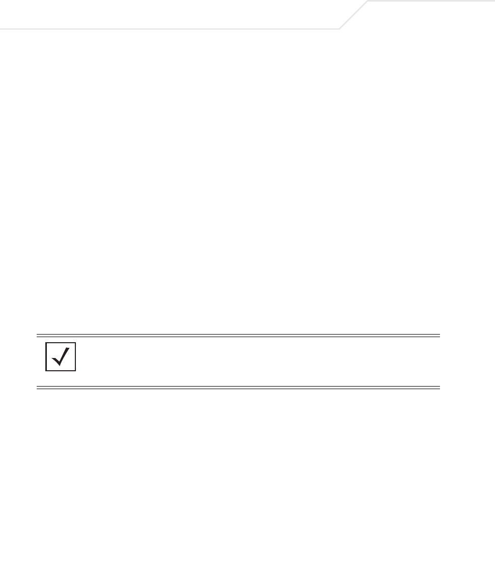
AP-51xx Access Point Product Reference Guide
5-38
9. Click Apply to save any changes to the New QoS Policy or Edit QoS Policy screen to return
to the Quality of Service Configuration screen. Navigating away from the screen without
clicking Apply results in all changes to the screens being lost.
10. Click Cancel to securely exit the New QoS Policy or Edit QoS Policy screen to return to the
Quality of Service Configuration screen.
11. Click Logout within the Quality of Service Configuration screen to securely exit the access
point Symbol Access Point applet. A prompt displays confirming the logout before the applet
is closed.
U-APSD (WMM Power Save) Support
The access point now supports Unscheduled Automatic Power Save Delivery (U-APSD), often referred
to as WMM Power Save. U-APSD provides a periodic frame exchange between a voice capable MU
and the access point during a VoIP call, while legacy power management is still utilized for typical
data frame exchanges. The access point and its associated MU activate the new U-APSD power save
approach when a VoIP traffic stream is detected. The MU then buffers frames from the voice traffic
stream and sends a VoIP frame with an implicit "poll" request to its associated access point. The
access point responds to the poll request with buffered VoIP stream frame(s). When a voice-enabled
MU wakes up at a designated VoIP frame interval, it sends a VoIP frame with an implicit "poll" request
to its associated access point. The AP -5131 responds to the poll request with buffered VoIP stream
frame(s).
NOTE The access point ships with the U-APSD feature disabled by default. It is
automatically enabled when WMM is enabled for a WLAN. Thus, U-APSD
is only functional when WMM is enabled. If WMM is disabled, then
U-APSD is disabled as well.

Network Management 5-39
5.3.1.4 Configuring WLAN Hotspot Support
The access point enables hotspot operators to provide user authentication and accounting without a
special client application. The access point uses a traditional Internet browser as a secure
authentication device. Rather than rely on built-in 802.11security features to control access point
association privileges, configure a WLAN with no WEP (an open network). The access point issues
an IP address to the user using a DHCP server, authenticates the user and grants the user to access
the Internet.
When a user visits a public hotspot and wants to browse to a Web page, they boot up their laptop
and associate with the local Wi-Fi network by entering the correct SSID. They then start a browser.
The hotspot access controller forces this un-authenticated user to a Welcome page from the hotspot
Operator that allows the user to login with a username and password.
The access point hotspot functionality requires the following:
• HTTP Redirection - Redirects unauthenticated users to a specific page specified by the
Hotspot provider.
• User authentication - Authenticates users using a Radius server.
• Walled garden support - Enables a list of IP address (not domain names) to be accessed
without authentication.
• Billing system integration - Sends accounting records to a Radius accounting server.
To configure hotspot functionality for an access point WLAN:
1. Ensure the Enable Hotspot checkbox is selected from within the target WLAN screen, and
ensure the WLAN is properly configured.
Any of the sixteen WLANs on the access point can be configured as a hotspot. For hotspot
enabled WLANs, DHCP, DNS,HTTP and HTTP-S traffic is allowed (before you login to the
hotspot), while TCP/IP packets are redirected to the port on the subnet to which the WLAN
is mapped. For WLANs that are not hotspot-enabled, all packets are allowed.
2. Click the Configure Hotspot button within the WLAN screen to display the Hotspot
Configuration screen for that target WLAN.
CAUTION When using the access point’s hotspot functionality, ensure MUs are
re-authenticated when changes are made to the characteristics of a
hotspot enabled WLAN, as MUs within the WLAN will be dropped
from access point device association.
!
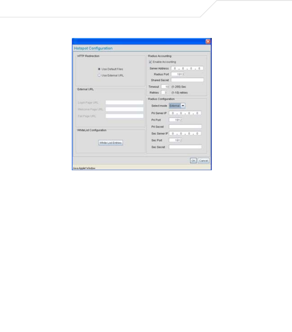
AP-51xx Access Point Product Reference Guide
5-40
3. Refer to the HTTP Redirection field to specify how the Login, Welcome, and Fail pages are
maintained for this specific WLAN. The pages can be hosted locally or remotely.
.
4. Use the External URL field to specify the location of the login page, welcome page and fail
page used for hotspot access. Defining these settings is required when the Use External
URL checkbox has been selected within the HTTP Redirection field.
Use Default Files Select the Use Default Files checkbox if the login, welcome and
fail pages reside on the access point.
Use External URL Select the Use External URL checkbox to define a set of external
URLs for hotspot users to access the login, welcome and fail pages.
To create a redirected page, you need to have a TCP termination
locally. On receiving the user credentials from the login page, the
access point connects to a radius server, determines the identity of
the connected wireless user and allows the user to access the
Internet based on successful authentication.
Login Page URL Define the complete URL for the location of the Login page. The
Login screen will prompt the hotspot user for a username and
password to access the Welcome page.

Network Management 5-41
5. Click the White List Entries button (within the WhiteList Configuration field) to create
a set of allowed destination IP addresses. These allowed destination IP addresses are called
a White List. Ten configurable IP addresses are allowed for each WLAN. For more
information, see Defining the Hotspot White List on page 5-42.
6. Refer to the Radius Accounting field to enable Radius accounting and specify the a
timeout and retry value for the Radius server.
7. Refer to the Radius Configuration field to define a primary and secondary Radius server
port and shared secret password.
Welcome Page URL Define the complete URL for the location of the Welcome page. The
Welcome page asserts the hotspot user has logged in successfully
and can access the Internet.
Fail Page URL Define the complete URL for the location of the Fail page. The Fail
screen asserts the hotspot authentication attempt failed, you are
not allowed to access the Internet and you need to provide correct
login information to access the Internet.
Enable Accounting Select the Enable Accounting checkbox to enable a Radius
Accounting Server used for Radius authentication for a target
hotspot user.
Server Address Specify an IP address for the external Radius Accounting server
used to provide Radius accounting for the hotspot. If using this
option, an internal Radius server cannot be used. The IP address of
the internal Radius server is fixed at 127.0.0.1 and cannot be used
for the external Radius server.
Radius Port Specify the port on which the Radius accounting server is listening.
Shared Secret Specify a shared secret for accounting authentication for the
hotspot. The shared secret is required to match the shared secret
on the external Radius accounting server.
Timeout Set the timeout value in seconds (1-255) used to timeout users
accessing the Radius Accounting server if they have not
successfully accessed the Accounting Server.
Retries Define the number of retries (1-10) the user is allowed to access
the Radius Accounting Server if the first attempt fails. The default
is 1.

AP-51xx Access Point Product Reference Guide
5-42
8. Click OK to save any changes to the Hotspot Configuration screen. Navigating away from
the screen without clicking Apply results in all changes to the screens being lost.
9. Click Cancel (if necessary) to undo any changes made. Cancel reverts the settings displayed
on the Hotspot Configuration screen to the last saved configuration.
Defining the Hotspot White List
To host a Login, Welcome or Fail page on the external Web server, the IP address of that Web server
should be in access point’s White List.
Select mode Use the Select mode drop-down menu to define whether an
Internal or External server is to be used for the primary server.
Pri Server IP Define the IP address of the primary Radius server. This is the
address of your first choice for Radius server.
Pri Port Enter the TCP/IP port number for the server acting as the primary
Radius server. The default port is 1812.
Pri Secret Enter the shared secret password used with the primary Radius
Server.
Sec Server IP Define the IP address of the secondary Radius server. This is the
address of your second choice for Radius server.
Sec Port Enter the TCP/IP port number for the server acting as the secondary
Radius server. The default port is 1812.
Sec Secret Enter the shared secret password used with the secondary Radius
Server.
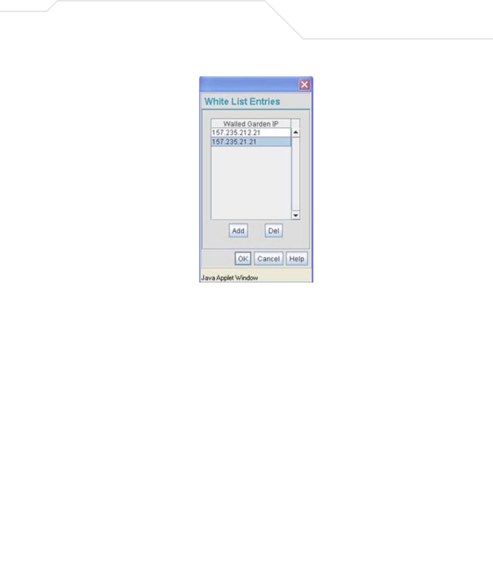
Network Management 5-43
When a client requests a URL from a Web server, the login handler returns an HTTP redirection status
code (for example, 301 Moved Permanently), which indicates to the browser it should look for the
page at another URL. This other URL can be a local or remote login page (based on the hotspot
configuration). The login page URL is specified in the location’s HTTP header.
To host a Login page on the external Web server, the IP address of the Web server should be in the
White list (list of IP addresses allowed to access the server) configuration. Ensure the Login page is
designed so the submit action always posts the login data on the access point.
To define the White List for a target WLAN:
1. Click the White List Entries button from within the WLAN’s Hotspot Config screen.
2. Click the Add button to define an IP address for an allowed destination IP address.
3. Select a White List entry and click the Del button to remove the address from the White List.
4. Click OK to return to the Hotspot Config screen where the configuration can be saved by
clicking the Apply button.
Now user enters his/her credentials on Login page and submits the page to AP5131. Login
Handler will execute a CGI script, which will use this data as input.
5. Click Cancel to return to the Hotspot Config screen without saving any of the White List
entries defined within the White List Entries screen.
AP-51xx Access Point Product Reference Guide
5-44
5.3.2 Setting the WLAN’s Radio Configuration
Each access point WLAN can have a separate 802.11a or 802.11b/g radio configured and mapped to
that WLAN. The first step is to enable the radio.
One of two possible radio configuration pages are available on the access point depending on which
model SKU is purchased. If the access point is a single-radio model, the Radio Configuration screen
enables you to configure the single radio for either 802.11a or 802.11b/g use. The Radio Configuration
screen contains two radio buttons whose selection is mutually exclusive.
If the access point is a dual-radio model, the Radio Configuration screen enables you to configure
one radio for 802.11a use and the other for 802.11b/g (no other alternatives exist for the dual-radio
model). Using a dual-radio access point, individual 802.11a and 802.11b/g radios can be enabled or
disabled using the Radio Configuration screen checkboxes.
The Radio Configuration screen displays with two tabs. One tab each for the access point’s radios.
Verify both tabs are selected and configured separately to enable the radio(s), and set their mesh
networking definitions.
To set the access point radio configuration (this example is for a dual-radio access point):
1. Select Network Configuration -> Wireless -> Radio Configuration from the access
point menu tree.
NOTE This section describes mesh networking (setting the radio’s base and
client bridge configuration) at a high level. For a detailed overview on the
theory of mesh networking, see Mesh Networking Overview on page 9-1.
For detailed information on the implications of setting the mesh network
configuration, see Configuring Mesh Networking Support on page 9-5. To
review a use case on mesh networking, see
Usage Scenario - Trion Enterprises on page 9-15.
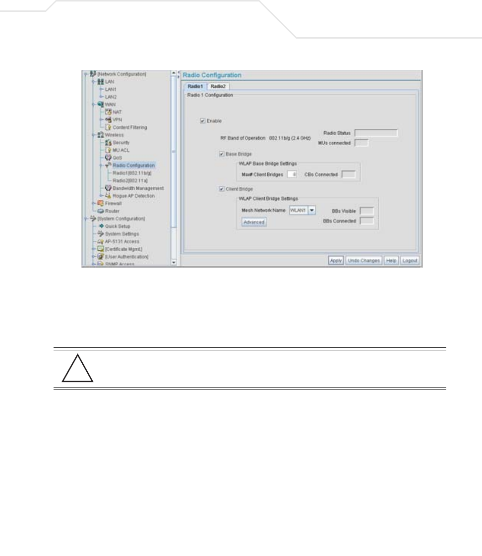
Network Management 5-45
2. Enable the radio(s) using the Enable checkbox(es).
Refer to RF Band of Operation parameter to ensure you are enabling the correct 802.11a
or 802.11b/g radio. After the settings are applied within this Radio Configuration screen, the
Radio Status and MUs connected values update. If this is an existing radio within a mesh
network, these values update in real-time.
3. Select the Base Bridge checkbox to allow the access point radio to accept client bridge
connections from other access points in client bridge mode. The base bridge is the acceptor
of mesh network data from those client bridges within the mesh network and never the
initiator.
4. If the Base Bridge checkbox has been selected, use the Max# Client Bridges parameter
to define the client bridge load on a particular base bridge.
CAUTION If a radio is disabled, be careful not to accidentally configure a new
WLAN, expecting the radio to be operating when you have forgotten it
was disabled.
!
AP-51xx Access Point Product Reference Guide
5-46
The maximum number of client bridge connections per radio is 12, with 24 representing the
maximum for dual-radio models.
Once the settings within the Radio Configuration screen are applied (for an initial
deployment), the current number of client bridge connections for this specific radio displays
within the CBs Connected field. If this is an existing radio within a mesh network, this
value updates in real-time.
5. Select the Client Bridge checkbox to enable the access point radio to initiate client bridge
connections with other mesh network supported access point’s using the same WLAN.
If the Client Bridge checkbox has been selected, use the Mesh Network Name drop-down
menu to select the WLAN (ESS) the client bridge uses to establish a wireless link. The
default setting, is (WLAN1). Symbol recommends creating (and naming) a WLAN specifically
for mesh networking support to differentiate the Mesh supported WLAN from non-Mesh
supported WLANs.
Once the settings within the Radio Configuration screen are applied (for an initial
deployment), the current number of base bridges visible to the radio displays within the BBs
Visible field, and the number of base bridges currently connected to the radio displays
CAUTION An access point is Base Bridge mode logs out whenever a Client
Bridge associates to the Base Bridge over the LAN connection. This
problem is not experienced over the access point’s WAN connection. If
this situation is experienced, log-in to the access point again.
CAUTION A problem could arise if a Base Bridge’s Indoor channel is not
available on an Outdoor Client Bridge's list of available channels. As
long as an Outdoor Client Bridge has the Indoor Base Bridge channel
in its available list of channels, it can associate to the Base Bridge.
CAUTION An access point in client bridge mode cannot use a WLAN configured
with a Kerberos or EAP 802.1x based security scheme, as these
authentication types secure user credentials not the mesh network
itself.
NOTE Ensure you have verified the radio configuration for both Radio 1 and
Radio 2 before saving the existing settings and exiting the Radio
Configuration screen.
!
!
!

Network Management 5-47
within the BBs Connected field. If this is an existing radio within a mesh network, these
values update in real-time.
6. Click the Advanced button to define a prioritized list of access points to define Mesh
Connection links. For a detailed overview on mesh networking and how to configure the
radio for mesh networking support, see Configuring Mesh Networking on page 9-1.
7. Click Apply to save any changes to the Radio Configuration screen. Navigating away from
the screen without clicking Apply results in all changes to the screens being lost.
8. Click Undo Changes (if necessary) to undo any changes made. Undo Changes reverts the
settings displayed on the Radio Configuration screen to the last saved configuration.
9. Click Logout to securely exit the access point Symbol Access Point applet. A prompt
displays confirming the logout before the applet is closed.
Once the target radio has been enabled from the Radio Configuration screen, configure
the radio’s properties by selecting it from the access point menu tree.
For more information, see Configuring the 802.11a or 802.11b/g Radio on page 5-47.
5.3.2.1 Configuring the 802.11a or 802.11b/g Radio
Configure an 802.11a or 802.11b/g radio by selecting the radio’s name (as defined using the 802.11a
or 802.11b/g radio configuration screen described below) as a sub-menu item under the Radio
Configuration menu item. Use the radio configuration screen to set the radio’s placement properties,
define the radio’s threshold and QoS settings, set the radio’s channel and antenna settings and define
beacon and DTIM intervals.
To configure the access point’s 802.11a or 802.11b/g radio:
1. Select Network Configuration -> Wireless -> Radio Configuration -> Radio1 (default
name) from the access point menu tree.
CAUTION When defining a Mesh configuration and changes are saved, the
mesh network temporarily goes down. The Mesh network is
unavailable because the access point radio is reconfigured when
applying changes. This can be problematic for users making changes
within a deployed mesh network. If updating the mesh network using
a LAN connection, the access point applet loses connection and the
connection must be re-instated. If updating the mesh network using a
WAN connection, the access point applet does not lose connection,
but the mesh network is unavailable until the changes have been
applied.
!
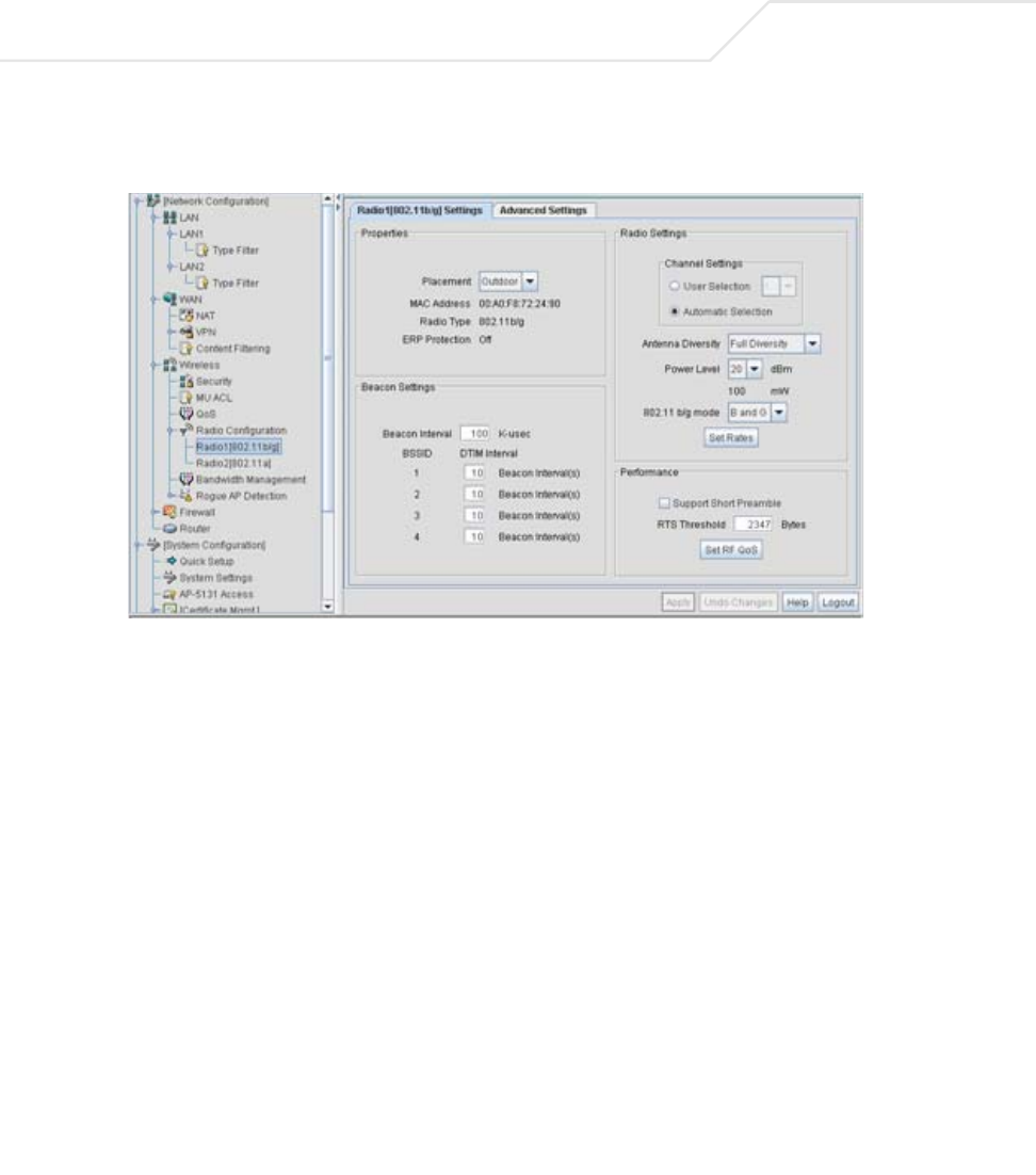
AP-51xx Access Point Product Reference Guide
5-48
On a single-radio model, Radio1 could either be an 802.11a or 802.11b/g radio depending
on which radio has been enabled.
2. Configure the Properties field to assign a name and placement designation for the radio.
Placement Use the Placement drop-down menu to specify whether the
radio is located outdoors or indoors. Default placement depends on
the country of operation selected for the access point.
MAC Address The access point, like other Ethernet devices, has a unique,
hardware encoded Media Access Control (MAC) or IEEE address.
MAC addresses determine the device sending or receiving data. A
MAC address is a 48-bit number written as six hexadecimal bytes
separated by colons. For example: 00:A0:F8:24:9A:C8
Radio Type The Radio Type parameter simply displays the radio type as
802.11a or 802.11b/g. This field is read only and always displays
the radio type selected from the access point menu tree under the
Radio Configuration item.

Network Management 5-49
3. Configure the Radio Settings field to assign a channel, antenna diversity setting, radio
transmit power level and data rate.
ERP Protection Extended Rate PHY (ERP) allows 802.11g MUs to interoperate with
802.11b only MUs. ERP Protection is managed automatically by the
access point and informs users when 802.11b MUs are present
within the access point’s coverage area. The presence of 802.11b
MUs within the 802.11g coverage area negatively impacts network
performance, so this feature should looked to as an indicator of
why network performance has been degraded.
Channel Setting The following channel setting options exist:
User Selection - If selected, use the drop-down menu to specify
the legal channel for the intended country of operation. The drop-
down menu is not available if this option is not selected.
Automatic Selection - Enables the access point to auto-select
the channel of operation. For example, if three access point’s are
operating on 802.11b/g, each access point would be set to a non-
overlapping channel (1, 6 and 11). If using the access point’s
802.11a radio, a Uniform Spreading option is available (and is
the default setting for the 802.11a radio). To comply with Dynamic
Frequency Selection (DFS) requirements in the European Union, the
802.11a radio uses a randomly selected channel each time the
access point is powered on.
Antenna Diversity Specifies the antenna selection for the 802.11a radio. Options
include Primary Only, Secondary Only and Full Diversity. The default
setting is Primary. However, Diversity can improve performance
and signal reception in areas where interference is significant and
is recommended when two antennas are supported.
Power Level The Power Level parameter defines the transmit power of the
802.11a or 802.11b/g antenna(s). The values are expressed in dBm
and mW.

AP-51xx Access Point Product Reference Guide
5-50
802.11 b/g mode Specify b only, g only or b and g to define whether the 802.11b/
g radio transmits in the 2.4 Ghz band exclusively for 802.11b
(legacy) clients or transmits in the 2.4 Ghz band for 802.11g clients.
Selecting b and g enables the access point to transmit to both b
and g clients if legacy clients (802.11b) partially comprise the
network. Select accordingly based on the MU requirements of the
network. This parameter does not apply to access point 802.11a
radios.
Set Rates Click the Set Rates button to display a window for selecting
minimum and maximum data transmit rates for the radio. At least
one Basic Rate must be selected as a minimum transmit rate
value. Supported Rates define the data rate the radio defaults to
if a higher selected data rate cannot be maintained. Click OK to
implement the selected rates and return to the 802.11a or
802.11b/g radio configuration screen. Clicking Cancel reverts the
Set Rates screen to the last saved configuration. Symbol
recommends using the default rates unless qualified to understand
the performance risks of changing them. The appearance of the Set
Rates screen varies depending on the 802.11a or 802.11b/g used,
as the dates rates available to the two radios are different.
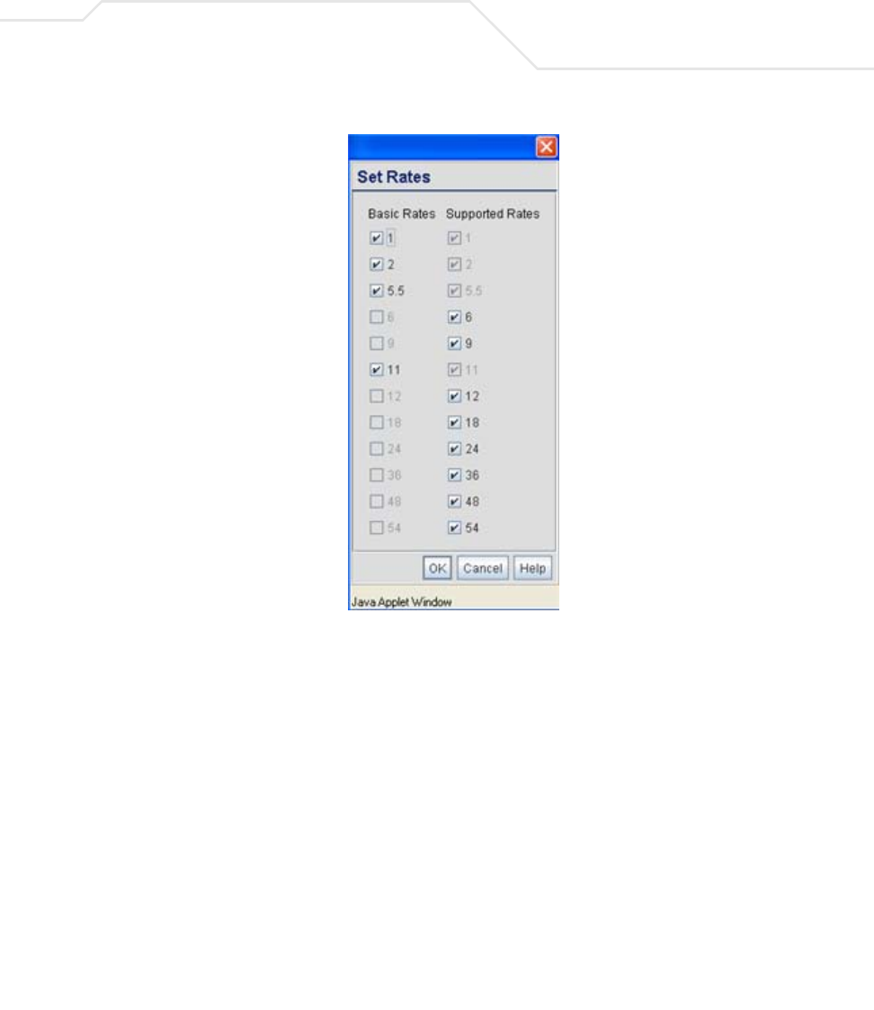
Network Management 5-51
4. Refer to the Beacon Settings field to set the radio beacon and DTIM intervals.
Beacon Interval The beacon interval controls the performance of power save
stations. A small interval may make power save stations more
responsive, but it will also cause them to consume more battery
power. A large interval makes power save stations less responsive,
but could increase power savings.
The default is 100. Avoid changing this parameter as it can
adversely affect performance.
DTIM Interval The DTIM interval defines how often broadcast frames are
delivered for each of the four access point BSSIDs. If a system has
an abundance of broadcast traffic and it needs to be delivered
quickly, Symbol recommends decreasing the DTIM interval for that
specific BSSID. However, decreasing the DTIM interval decreases
the battery life on power save stations. The default is 10 for each
BSSID. Symbol recommends using the default value unless
qualified to understand the performance risks of changing it.

AP-51xx Access Point Product Reference Guide
5-52
5. Configure the Performance field to set the preamble, thresholds values, data rates and
QoS values for the radio.
Support Short
Preamble
The preamble is approximately 8 bytes of packet header generated
by the access point and attached to the packet prior to
transmission from the 802.11b radio. The preamble length for
802.11b transmissions is data rate dependant. The short preamble
is 50% shorter than the long preamble. Leave the checkbox
unselected if in a mixed MU/AP environment, as MUs and the
access point are required to have the same RF Preamble settings
for interoperability. The default is Disabled. The preamble length
for 802.11a and 802.11g transmissions is the same, with no long or
short preamble lengths.
RTS Threshold RTS allows the access point to use RTS (Request To Send) on
frames longer than the specified length. The default is 2341bytes.
Set RF QoS Click the Set RF QoS button to display the Set RF QOS screen to
set QoS parameters for the radio. Do not confuse with the QoS
configuration screen used for a WLAN. The Set RF QoS screen
initially appears with default values displayed.
Select manual from the Select Parameter set drop-down menu
to edit the CW min and CW max (contention window), AIFSN
(Arbitrary Inter-Frame Space Number) and TXOPs Time for each
Access Category. These are the QoS policies for the 802.11a or
802.11b/g radio, not the QoS policies configured for the WLAN (as
created or edited from the Quality of Service Configuration
screen).
Symbol recommends only advanced users manually set these
values. If the type of data-traffic is known, use the drop-down
menu to select a 11g-wifi, 11b-wifi, 11g-default, 11b-default,
11g-voice or 11b-voice option. Wifi represents multimedia
traffic, default is typical data traffic and voice is for “Voice-Over-IP”
supported wireless devices.
Click OK to implement the selected QoS values and return to the
802.11a or 802.11b/g radio configuration screen. Clicking Cancel
reverts the screen to the last saved configuration.
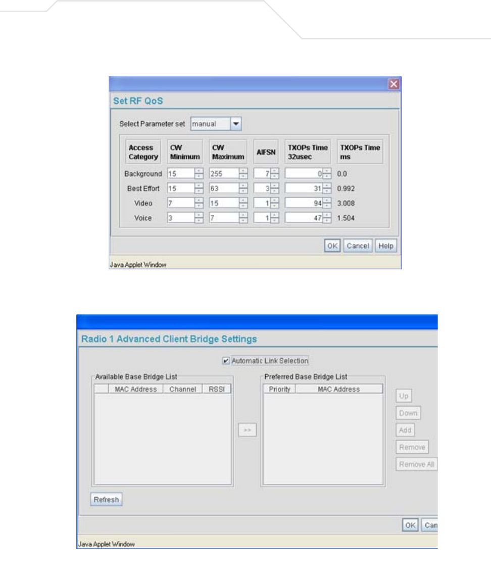
Network Management 5-53
6. Select the Advanced Settings tab to strategically map BSSIDs to WLANs in order to define
them as primary WLANs.
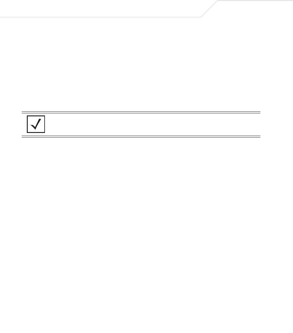
AP-51xx Access Point Product Reference Guide
5-54
Defining Primary WLANs allows an administrator to dedicate BSSIDs (4 BSSIDs are
available for mapping) to WLANs. From that initial BSSID assignment, Primary WLANs can
be defined from within the WLANs assigned to BSSID groups 1 through 4. Each BSSID
beacons only on the primary WLAN.
The user should assign each WLAN to its own BSSID. In cases where more than four WLANs
are required, WLANs should be grouped according to their security policies so all of the
WLANs on a BSSID have the same security policy. It is generally a bad idea to have WLANs
with different security policies on the same BSSID, as this will result in warning or error
messages.
7. Use the Primary WLAN drop-down menu to select a WLAN from those WLANs sharing the
same BSSID. The selected WLAN is the primary WLAN for the specified BSSID.
8. Click Apply to save any changes to the Radio Settings and Advanced Settings screens.
Navigating away from the screen without clicking Apply results in changes to the screens
being lost.
NOTE If using a single-radio access point, there are 4 BSSIDs available. If using
a dual-radio access point, 4 BSSIDs for the 802.11b/g radio and 4 BSSIDs
for the 802.11a radio are available.
WLAN Lists the WLAN names available to the 802.11a or 802.11b/g radio
that can be assigned to a BSSID.
BSSID Assign a BSSID value of 1 through 4 to a WLAN in order to map the
WLAN to a specific BSSID.
BC/MC Cipher A read only field displaying the downgraded BC/MC (Broadcast/
Multicast) cipher for a WLAN based on the BSSID and VLAN ID to
which it has been mapped.
Status Displays the following color coded status:
Red - Error (Invalid Configuration)
Yellow - Warning (Broadcast Downgrade)
Green - Good (Configuration is OK)
Message Displays the verbal status of the WLAN and BSSID assignments. If
the Status column displays green, the Message will typically be
Configuration is OK. If yellow, a description of invalid
configuration displays.
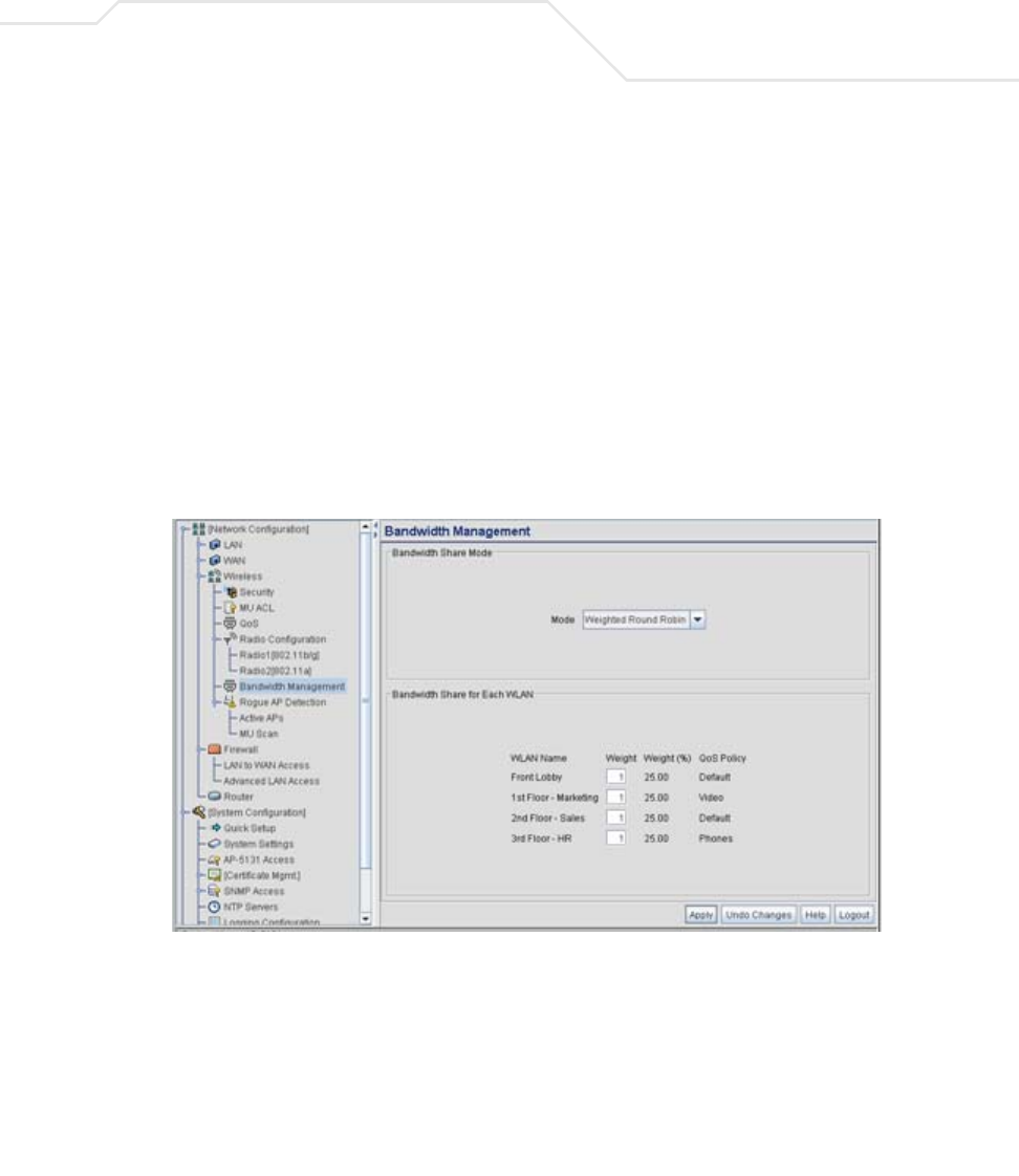
Network Management 5-55
9. Click Undo Changes (if necessary) to undo any changes made to the screen and its sub-
screens. Undo Changes reverts the settings to the last saved configuration.
10. Click Logout to securely exit the access point Symbol Access Point applet. A prompt
displays confirming the logout before the applet is closed.
5.3.3 Configuring Bandwidth Management Settings
The access point can be configured to grant individual WLAN’s network bandwidth priority levels. Use
the Bandwidth Management screen to control the network bandwidth allotted to WLANs. Symbol
recommends defining a weighed scheme as needed when WLAN traffic supporting a specific
network segment becomes critical.
1. Select Network Configuration -> Wireless -> Bandwidth Management from the
access point menu tree.
2. Use the Bandwidth Share Mode drop-down menu to define the order enabled WLANs
receive access point services. Select one of the following three options:
First In First Out WLANs receive services from the access point on a first-come,
first-served basis. This is the default setting.
Round-Robin Each WLAN receives access point services in turn as long the
access point has data traffic to forward.

AP-51xx Access Point Product Reference Guide
5-56
3. Configure the Bandwidth Share for Each WLAN field to set a raw weight (for WLANs
using the Weighted Round-Robin option) for each WLAN. The weight% changes as the
weight is entered.
If a WLAN has not been enabled from the Wireless screen, it is not configurable using the
Bandwidth Management screen. To enable a specific WLAN, see
Enabling Wireless LANs (WLANs) on page 5-22.
4. Click Apply to save any changes to the Bandwidth Management screen. Navigating away
from the screen without clicking Apply results in all changes to the screens being lost.
5. Click Undo Changes (if necessary) to undo any changes made. Undo Changes reverts the
settings displayed on the Bandwidth Management screen to the last saved configuration.
6. Click Logout to securely exit the access point Symbol Access Point applet. A prompt
displays confirming the logout before the applet is closed.
Weighted Round-
Robin
If selected, a weighting (prioritization) scheme (configured within
the QoS Configuration screen) is used to define which WLANs
receive access point resources first.
WLAN Name Displays the name of the WLAN. This field is read-only. To change
the name of the WLAN, see
Creating/Editing Individual WLANs on page 5-24.
Weight This column is not available unless Weighted Round-Robin is
selected. Assign a weight to each WLAN. This percentage equals
the access point bandwidth share for that WLAN when network
traffic is detected.
Weight (%) This column is automatically updated with the appropriate WLAN
bandwidth share when the Weight is modified.
QoS Policy Displays the name of the QoS policy defined for each WLAN within
the Quality of Service for WLAN screen. If no policy has been
set, the WLAN uses the default policy. For information on assigning
QoS policies for specific WLANs, see
Setting the WLAN Quality of Service (QoS) Policy on page 5-33.
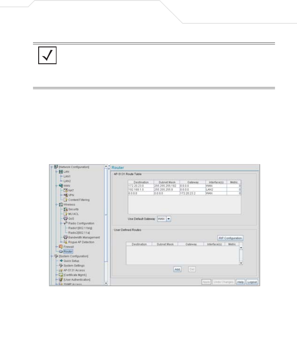
Network Management 5-57
5.4 Configuring Router Settings
The access point router uses routing tables and protocols to forward data packets from one network
to another. The access point router manages traffic within the network, and directs traffic from the
WAN to destinations on the access point managed LAN. Use the access point Router screen to view
the router's connected routes. To access the Router screen.
1. Select Network Configuration -> Router from the access point menu tree.
2. Refer to the access point Router Table field to view existing routes.
The access point Router Table field displays a list of connected routes between an enabled
subnet and the router. These routes can be changed by modifying the IP address and subnet
masks of the enabled subnets.
The information in the access point Router Table is dynamically generated from settings
applied on the WAN screen. The destination for each subnet is its IP address. The subnet
NOTE Though the Rogue AP and Firewall features appear after the Bandwidth
Management features within the access point menu tree, they are
described in Chapter 6, Configuring Access Point Security on page 6-1, as
both items are data protection functions. More specifically, see,
Configuring Firewall Settings on page 6-25 and Configuring Rogue AP
Detection on page 6-52.

AP-51xx Access Point Product Reference Guide
5-58
mask (or network mask) and gateway settings are those belonging to each subnet. Displayed
interfaces are those associated with destination IP addresses. To change any of the network
address information within the WAN screen, see Configuring WAN Settings on page 5-14.
3. From the Use Default Gateway drop-down menu, select the WAN or either of the two
LANs (if enabled) to server as the default gateway to forward data packets from one network
to another.
4. To set or view the RIP configuration, click the RIP Configuration button.
Routing Information Protocol (RIP) is an interior gateway protocol that specifies how routers
exchange routing-table information. The Router screen also allows the administrator to
select the type of RIP and the type of RIP authentication used by the switch. For more
information on configuring RIP, see Setting the RIP Configuration on page 5-58.
5. Use the User Defined Routes field to add or delete static routes.
The User Defined Routes field allows the administrator to view, add or delete internal static
(dedicated) routes.
a. Click the Add button to create a new table entry.
b. Highlight an entry and click the Del (delete) button to remove an entry.
c. Specify the destination IP address, subnet mask, and gateway information for the
internal static route.
d. Select an enabled subnet from the Interface(s) column’s drop-down menu to complete
the table entry. Information in the Metric column is a user-defined value (from 1 to
65535) used by router protocols to determine the best hop routes.
6. Click the Apply button to save the changes.
7. Click Logout to securely exit the access point Symbol Access Point applet. A prompt
displays confirming the logout before the applet is closed.
5.4.1 Setting the RIP Configuration
To set the RIP configuration:
1. From within the RIP Configuration field, select the RIP Type from the drop-down menu. The
following options are available:
No RIP The No RIP option prevents the access point’s router from
exchanging routing information with other routers. Routing
information may not be appropriate to share, for example, if the
access point manages a private LAN.

Network Management 5-59
2. Select a routing direction from the RIP Direction drop-down menu. Both (for both
directions), Rx only (receive only), and TX only (transmit only) are available options.
RIP v1 RIP version 1 is a mature, stable, and widely supported protocol. It
is well suited for use in stub networks and in small autonomous
systems that do not have enough redundant paths to warrant the
overhead of a more sophisticated protocol.
RIP v2 (v1 compat) RIP version 2 (compatible with version 1) is an extension of RIP v1’s
capabilities, but it is still compatible with RIP version 1. RIP version
2 increases the amount of packet information to provide the a
simple authentication mechanism to secure table updates.
RIP v2 RIP version 2 enables the use of a simple authentication
mechanism to secure table updates. More importantly, RIP version
2 supports subnet masks, a critical feature not available in RIP
version 1. This selection is not compatible with RIP version 1
support.
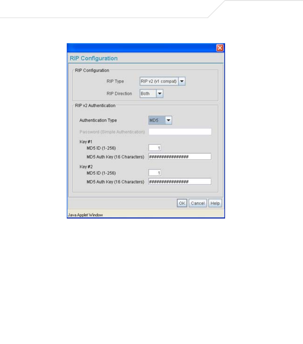
AP-51xx Access Point Product Reference Guide
5-60
3. If RIP v2 or RIP v2 (v1 compat) is the selected RIP type, the RIP v2 Authentication field
becomes active. Select the type of authentication to use from the Authentication Type
drop-down menu. Available options include:
None This option disables the RIP authentication.
Simple This option enable RIP version 2’s simple authentication
mechanism. This setting activates the Password (Simple
Authentication) field.
MD5 This option enables the MD5 algorithm for data verification. MD5
takes as input a message of arbitrary length and produces a 128-
bit fingerprint. The MD5 setting activates the RIP v2 Authentication
settings for keys (below).

Network Management 5-61
4. If the Simple authentication method is selected, specify a password of up to 15
alphanumeric characters in the Password (Simple Authentication) area.
5. If the MD5 authentication method is selected, fill in the Key #1 field (Key #2 is optional).
Enter any numeric value between 0 and 256 into the MD5 ID area. Enter a string consisting
of up to 16 alphanumeric characters in the MD5 Auth Key area.
6. Click the OK button to return to the Router screen. From there, click Apply to save the
changes.

AP-51xx Access Point Product Reference Guide
5-62

Configuring Access Point Security
Security measures for the access point and its WLANs are critical. Use the available access point
security options to protect the access point LAN from wireless vulnerabilities, and safeguard the
transmission of RF packets between the access point and its associated MUs.
WLAN security can be configured on an ESS by ESS basis on the access point. Sixteen separate
ESSIDs (WLANs) can be supported on an access point, and must be managed (if necessary) between
the 802.11a and 802.11b/g radio. The user has the capability of configuring separate security policies
for each WLAN. Each security policy can be configured based on the authentication (Kerberos, 802.1x
EAP) or encryption (WEP, KeyGuard, WPA/TKIP or WPA2/CCMP) scheme best suited to the coverage
area that security policy supports.
The access point can also create VPN tunnels to securely route traffic through a IPSEC tunnel and
block transmissions with devices interpreted as Rogue APs.
AP-51xx Access Point Product Reference Guide
6-2
6.1 Configuring Security Options
To configure the data protection options available on the access point, refer to the following:
• To set an administrative password for secure access point logins, see
Setting Passwords on page 6-3.
•Refer to Enabling Authentication and Encryption Schemes on page 6-5 to display security
policy screens used to configure the authetication and encryption schemes available to the
access point. These security policies can be used on more than one WLAN.
• To create a security policy supporting 802.1x EAP, see
Configuring 802.1x EAP Authentication on page 6-11.
• To define a security policy supporting Kerberos, see,
Configuring Kerberos Authentication on page 6-9.
• To create a security policy supporting WEP, see
Configuring WEP Encryption on page 6-16.
• To configure a security policy supporting KeyGuard, see,
Configuring KeyGuard Encryption on page 6-18.
• To define a security policy supporting WPA-TKIP, see
Configuring WPA Using TKIP on page 6-20.
• To create a security policy supporting WPA2-CCMP, see
Configuring WPA2-CCMP (802.11i) on page 6-22.
• To configure the access point to block specific kinds of HTTP, SMTP and FTP data traffic, see
Configuring Firewall Settings on page 6-25.
• To create VPN tunnels allowing traffic to route securely through a IPSEC tunnel to a private
network, see Configuring VPN Tunnels on page 6-33.
• To configure the access point to block transmissions with devices detected as Rogue AP’s
(hostile devices), see Configuring Rogue AP Detection on page 6-52.
NOTE Security for the access point can be configured in various locations
throughout the access point menu structure. This chapter outlines the
security options available to the access point, and the menu locations and
steps required to configure specific security measures.
Configuring Access Point Security 6-3
6.2 Setting Passwords
Before setting the access point security parameters, verify an administrative password for the access
point has been created to restrict access to the device before advanced device security is configured.
To password protect and restrict access point device access:
1. Connect a wired computer to the access point LAN port using a standard CAT-5 cable.
2. Set up the computer for TCP/IP DHCP network addressing and make sure the DNS settings
are not hardcoded.
3. Start up Internet Explorer (with Sun Micro Systems’ Java Runtime Environment (JRE) 1.5 or
higher installed) and type in the default IP address in the address field: 192.168.0.1. If the
default IP address has been changed, ensure the correct IP address is entered.
The access point Login screen displays.
4. Log in using the “admin” as the default User ID and “symbol” as the default Password.
NOTE For optimum compatibility use Sun Microsystems’ JRE 1.5 or higher
(available from Sun’s Web site), and be sure to disable Microsoft’s Java
Virtual Machine if it is installed.
NOTE DNS names are not supported as a valid IP address for the access point.
The user is required to enter a numerical IP address.
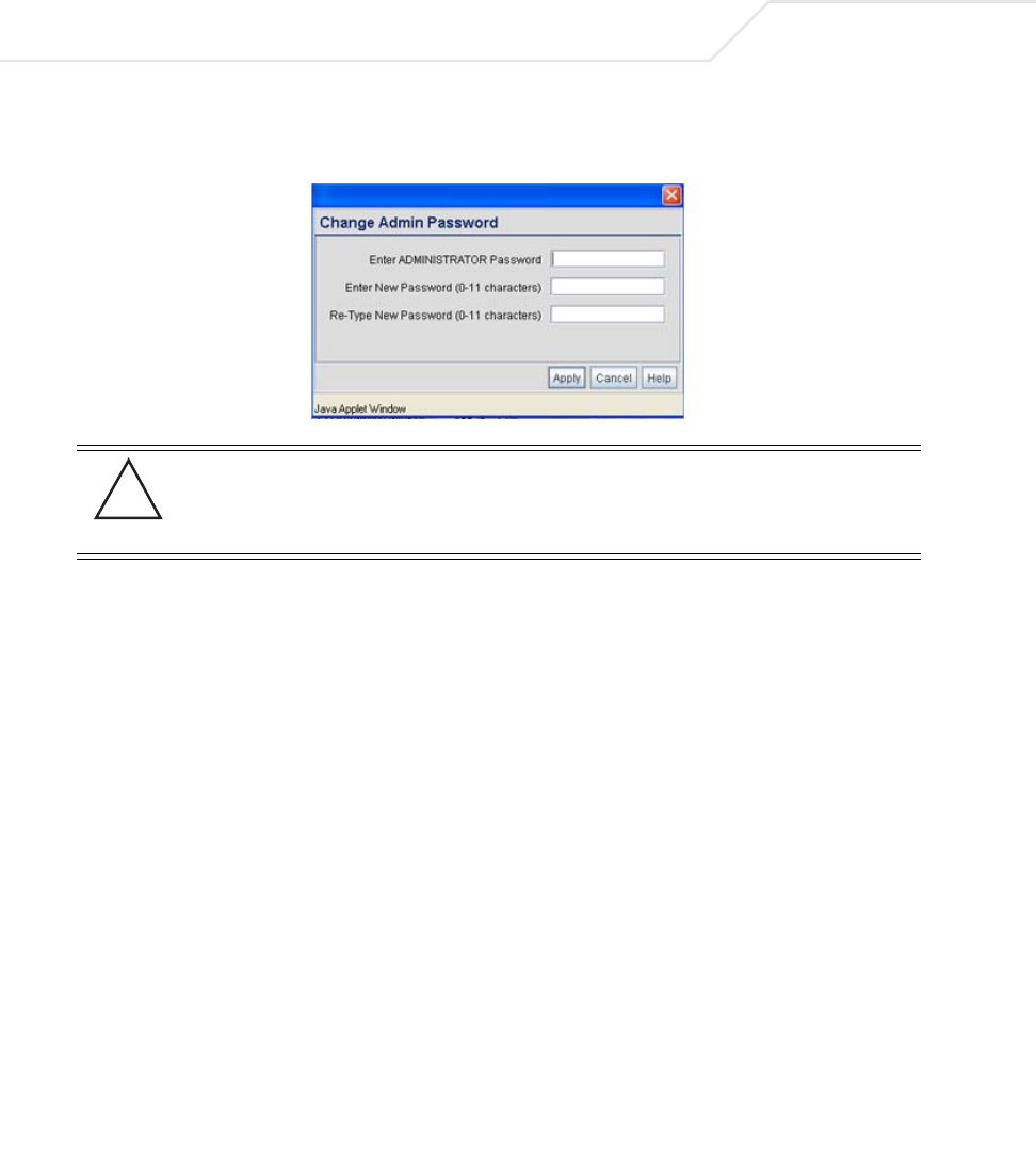
AP-51xx Access Point Product Reference Guide
6-4
If the default login is successful, the Change Admin Password window displays. Change
the default login and password to significantly decrease the likelihood of hacking.
5. Enter the previous password and the new admin password in the two fields provided. Click
the Apply button.
Once the admin password has been created/updated, the System Settings screen displays.
If the access point has not had its System Settings (device name, location etc.) configured,
see Configuring System Settings on page 4-2.
Once the password has been set, refer back to Configuring Security Options on page 6-2 to
determine which access point security feature to configure next.
6.2.1 Resetting the Access Point Password
The access point Command Line Interface (CLI) enables users who forget their password to reset it to
the factory default (symbol). From there, a new password can be defined.
To reset the password back to its default setting:
1. Connect one end of a null modem serial cable to the access point’s serial connector.
2. Attach the other end of the null modem serial cable to the serial port of a PC running
HyperTerminal or a similar emulation program.
3. Set the HyperTerminal program to use 19200 baud, 8 data bits, 1 stop bit, no parity, no flow
control and auto-detect for terminal emulation.
4. Press <ESC> or <Enter> to access the CLI.
CAUTION Restoring the access point’s configuration back to default settings
changes the administrative password back to “symbol.” If restoring
the configuration back to default settings, be sure you change the
administrative password accordingly.
!

Configuring Access Point Security 6-5
A serial connection has now been established and the user should be able to view the serial
connection window.
5. Reset the access point.
An access point can be reset by removing and re-inserting the LAN cable or removing and
re-inserting the power cable.
As the access point is re-booting, a “Press esc key to run boot firmware” message displays.
6. Quickly press <ESC>.
If the <ESC> key is pressed within three seconds a boot> prompt displays.
7. Type the following at the boot prompt:
passwd default
8. Reset the access point by typing the following at the boot prompt:
reset system
When the access point re-boots again, the password will return to its default value of
“symbol.” You can now access the access point.
6.3 Enabling Authentication and Encryption Schemes
To complement the built-in firewall filters on the WAN side of the access point, the WLAN side of the
access point supports authentication and encryption schemes. Authentication is a challenge-
response procedure for validating user credentials such as username, password, and sometimes
secret-key information. The access point provides two schemes for authenticating users: 802.1x EAP
and Kerberos.
Encryption applies a specific algorithm to alter its appearance and prevent unauthorized reading.
Decryption applies the algorithm in reverse to restore the data to its original form. Sender and
receiver must employ the same encryption/decryption method to interoperate.
Wired Equivalent Privacy (WEP) is available in two encryption modes: 40 bit (also called WEP 64) and
104 bit (also called WEP 128). The 104-bit encryption mode provides a longer algorithm (better
security) that takes longer to decode (hack) than the 40-bit encryption mode.
CAUTION If the <ESC> key is not pressed within three seconds after the “Press
esc key to run boot firmware” message displays, the access point will
continue to boot.
!
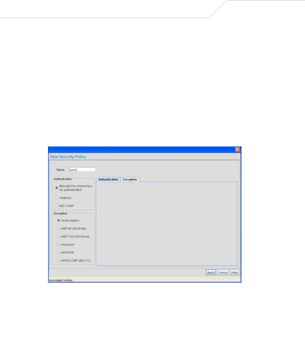
AP-51xx Access Point Product Reference Guide
6-6
Each WLAN (16 WLANs available in total to an access point regardless of the model) can have a
separate security policy. However, more than one WLAN can use the same security policy. Therefore,
to avoid confusion, do not name security policies the same name as WLANs. Once security policies
have been created, they are selectable within the Security field of each WLAN screen. If the
existing default security policy does not satisfy the data protection requirements of a specific WLAN,
a new security policy (using the authentication and encryption schemes discussed above) can be
created.
To enable an existing WLAN security policy or create a new policy:
1. Select Network Configuration -> Wireless -> Security from the access point menu tree.
The Security Configuration screen displays.
2. If a new security policy is required, click the Create button.
The New Security Policy screen displays with the Manually Pre-shared key/No
authentication and No Encryption options selected. Naming and saving such a policy (as
is) would provide no security and might only make sense in a guest network wherein no
sensitive data is either transmitted or received.
However, selecting any other authetnication or encryption checkbox displays a configuration
field for the selected security scheme within the New Security Policy screen.
Configuring Access Point Security 6-7
3. Use the Name field to define a logical security policy name.
Remember, multiple WLANs can share the same security policy, so be careful not to name
security policies after specific WLANs or risk defining a WLAN to single policy. Symbol
recommends naming the policy after the attributes of the authentication or encryption type
selected (for example, WPA2 Allow TKIP).
4. Enable and configure an Authentication option if necessary for the target security policy.
5. Enable and configure an Encryption option if necessary for the target security policy.
NOTE An existing security policy can be edited from the Security Configuration
screen by selecting an existing policy and clicking the Edit button. Use the
Edit Security Policy screen to edit the policy. For more information on
editing an existing security policy, refer to security configuration sections
described in steps 4 and 5.
Manually Pre-Shared
Key / No
Authentication
Select this button to disable authentication. This is the default
value for the Authentication field.
Kerberos Select the Kerberos button to display the Kerberos
Configuration field within the New Security Policy screen. For
specific information on configuring Kerberos, see
Configuring Kerberos Authentication on page 6-9.
802.1x EAP Select the 802.1x EAP button to display the 802.1x EAP Settings
field within the New Security Policy screen. For specific
information on configuring EAP, see
Configuring 802.1x EAP Authentication on page 6-11.
No Encryption If No Encryption is selected, encryption is disabled for the
security policy. If security is not an issue, this setting avoids the
overhead an encryption protocol causes on the access point. No
Encryption is the default value for the Encryption field.
WEP 64 (40-bit key) Select the WEP 64 (40 bit key) button to display the WEP 64
Settings field within the New Security Policy screen. For specific
information on configuring WEP 64, see
Configuring WEP Encryption on page 6-16.

AP-51xx Access Point Product Reference Guide
6-8
6. Click Apply to keep changes made within the New Security Policy screen (if any).
Configure encryption or authentication supported security policies by referring to the
following:
access point authentication:
• To create a security policy supporting Kerberos, see,
Configuring Kerberos Authentication on page 6-9.
• To define a security policy supporting 802.1x EAP, see
Configuring 802.1x EAP Authentication on page 6-11.
access point encryption:
• To create a security policy supporting WEP, see
Configuring WEP Encryption on page 6-16.
• To define a security policy supporting KeyGuard, see,
Configuring KeyGuard Encryption on page 6-18.
• To configure a security policy supporting WPA/TKIP, see
Configuring WPA Using TKIP on page 6-20.
• To create a security policy supporting WPA2/CCMP, see
Configuring WPA2-CCMP (802.11i) on page 6-22.
WEP 128 (104-bit key) Select the WEP 128 (104 bit key) button to display the WEP 128
Settings field within the New Security Policy screen. For specific
information on configuring WEP 128, see
Configuring WEP Encryption on page 6-16.
KeyGuard Select the KeyGuard button to display the KeyGuard Settings
field within the New Security Policy screen. For specific
information on configuring KeyGuard, see
Configuring KeyGuard Encryption on page 6-18.
WPA/TKIP Select the WPA/TKIP button to display the WPA/TKIP Settings
field within the New Security Policy screen. For specific
information on configuring WPA-TKIP, see
Configuring WPA Using TKIP on page 6-20.
WPA2/CCMP
(802.11i)
Select the WPA2/CCMP (802.11) button to display the WPA2/
CCMP Settings field within the New Security Policy screen. For
detailed information on configuring WPA2/CCMP, see
Configuring WPA2-CCMP (802.11i) on page 6-22.
Configuring Access Point Security 6-9
7. Click Cancel to return to the target WLAN screen without keeping any of the changes made
within the New Security Policy screen.
6.4 Configuring Kerberos Authentication
Kerberos (designed and developed by MIT) provides strong authentication for client/server
applications using secret-key cryptography. Using Kerberos, a client must prove its identity to a server
(and vice versa) across an insecure network connection.
Once a client and server use Kerberos to prove their identity, they can encrypt all communications to
assure privacy and data integrity. Kerberos can only be used on the access point with Symbol clients.
Kerberos uses the Network Time Protocol (NTP) for synchronizing the clocks of its Key Distribution
Center (KDC) server(s). Use the NTP Servers screen to specify the IP addresses and ports of available
NTP servers. Kerberos requires the Enable NTP on access point checkbox be selected for
authentication to function properly. See Configuring Network Time Protocol (NTP) on page 4-31 to
configure the NTP server.
To configure Kerberos on the access point:
1. Select Network Configuration -> Wireless -> Security from the access point menu tree.
If security policies supporting Kerberos exist, they appear within the Security
Configuration screen. These existing policies can be used as is, or their properties edited
by clicking the Edit button. To configure a new security policy supporting Kerberos, continue
to step 2.
2. Click the Create button to configure a new policy supporting Kerberos.
The New Security Policy screen displays with no authentication or encryption options
selected.
CAUTION Kerberos makes no provisions for host security. Kerberos assumes
that it is running on a trusted host with an untrusted network. If host
security is compromised, Kerberos is compromised as well
NOTE If 802.11a is selected as the radio used for a specific WLAN, the WLAN
cannot use a Kerberos supported security policy, as no 802.11a clients can
support Kerberos on the access point.
!
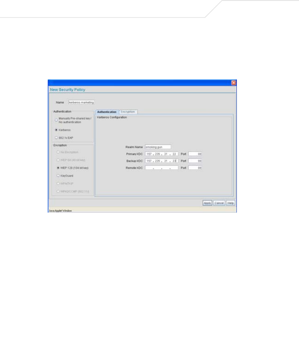
AP-51xx Access Point Product Reference Guide
6-10
3. Select the Kerberos radio button.
The Kerberos Configuration field displays within the New Security Policy screen.
4. Ensure the Name of the security policy entered suits the intended configuration or function
of the policy.
5. Set the Kerberos Configuration field as required to define the parameters of the Kerberos
authentication server and access point.
Realm Name Specify a realm name that is case-sensitive, for example,
SYMBOL.COM. The realm name is the name domain/realm name
of the KDC Server. A realm name functions similarly to a DNS
domain name. In theory, the realm name is arbitrary. However, in
practice a Kerberos realm is named by uppercasing the DNS
domain name that is associated with hosts in the realm.
Primary KDC Specify a numerical (non-DNS) IP address and port for the primary
Key Distribution Center (KDC). The KDC implements an
Authentication Service and a Ticket Granting Service, whereby an
authorized user is granted a ticket encrypted with the user's
password. The KDC has a copy of every user password.