SystemBase SG-1020WALL Serialgate User Manual Manual 1
SystemBase Co., Ltd. Serialgate Manual 1
Contents
- 1. Manual 1
- 2. Manual 2
Manual 1

SerialGate
User Guide
Ver 2.1a
2012. 09.10
SerialGate User Guide
2
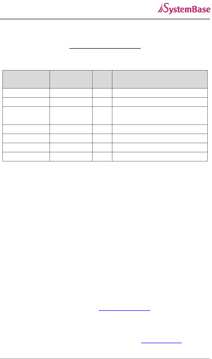
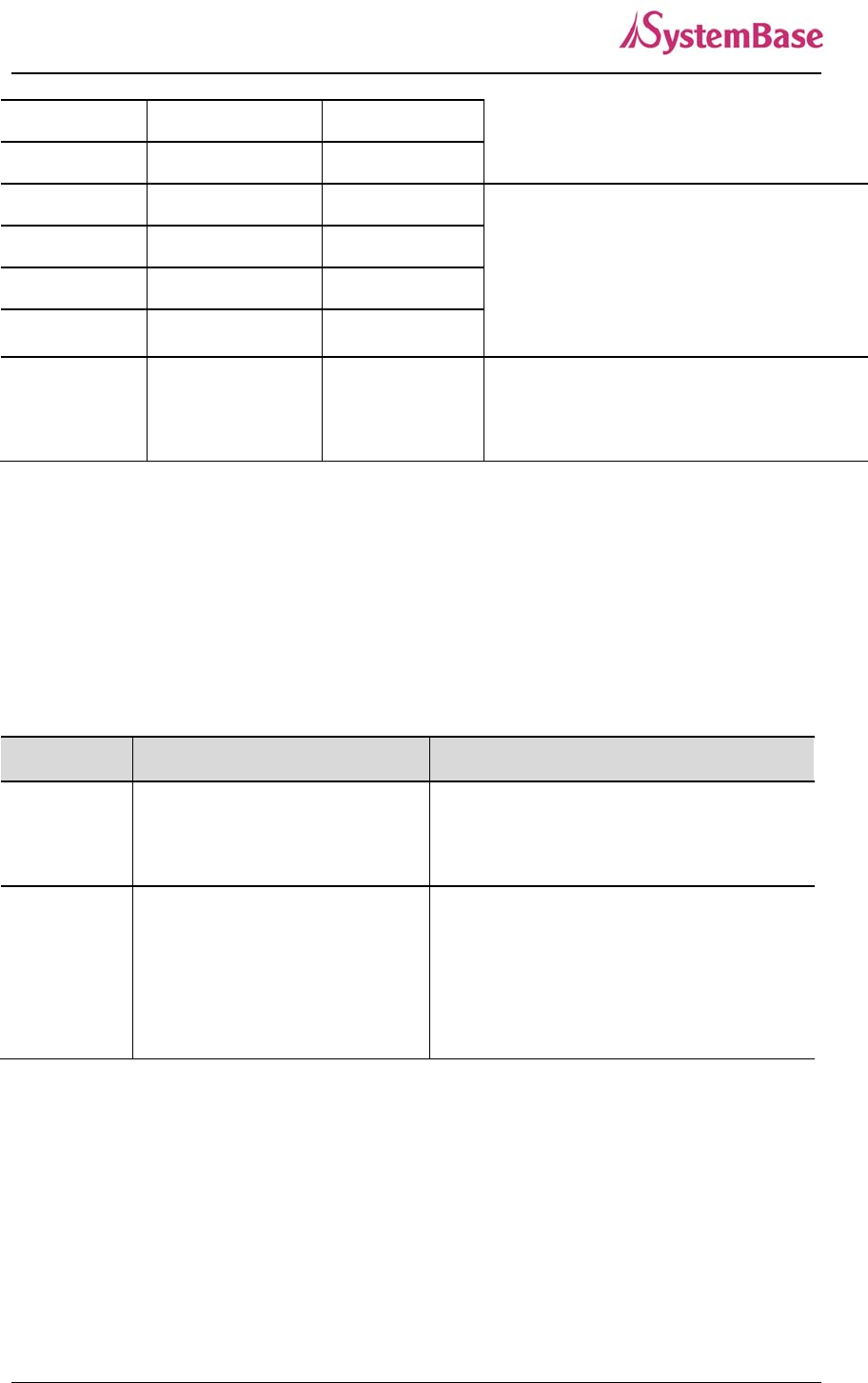
Revision History
Revision Date Document
Version Pages
Description
Apr. 10. 2012 2.0 All Initial release
Jun. 26. 2012 2.1 All New Firmware release
Sep. 10. 2012 2.1a All New Case of SG-1020(W)/ALL
release
Copyright 2009-2011 SystemBase Co., Ltd. All rights reserved.
Website http://www.sysbas.com/
Tel 02-855-0501
Fax 02-855-0580
16F Daerung Post Tower-1, 212-8, Guro-dong, Seoul, Korea
For any inquiries or comments, contact to tech@sysbas.com

SerialGate User Guide
3
Contents
Ch. 1 Introduction
About This Document
Who Should Read This Document
Manual Contents
SerialGate Documents
Technical Support
Ch. 2 Getting Started
Overview
Features
Package Component
Applications
Ch.3 Hardware Description
SerialGate-1010(W)ALL Exterior
SerialGate-1010(W)ALL LED/RESET
SerialGate-1020(W)ALL Exterior
SerialGate-1020(W)ALL LED/RESET
SerialGate-1010/1020 Exterior
SerialGate-1010/1020 LED/RESET
SerialGate-1040/1080 Exterior
SerialGate-1040/1080 LED/RESET
SerialGate-1160 Exterior
SerialGate-1160 LED/RESET
Pin Specification (SerialGate-1010/1020/1040/1080)
Pin Specification (SerialGate-1010(W)/ALL, SerialGate-1020(W)/ALL)
Pin Specification (SerialGate-1160)
Ch.4 Installation
Connection Guide
First-Time Boot up

SerialGate User Guide
4
Connecting to SerialGate
Ch.5 Configuration via Web
Connection
Setup Menu
Network Settings
Serial Settings
Wireless Settings
SNMP Settings
Change Password
Update Firmware
Factory Default
Save & Reboot
System Log
Ch.6 Configuration via Telnet
Connection
View Commands
Network Commands
Serial Commands
Username/Password Commands
System Commands
Ch.7 Configuration via LCD
LCD & Key Control
Main Menu
Network Setup
Port Setup
Status
System
Verification
Ch.8 Application
Com Port Redirector
TCP Server
TCP Client

SerialGate User Guide
5
Pair
Ch.9 Appendix
Troubleshooting
Firmware Update using FTP
Product Specification

SerialGate User Guide
6
Ch. 1 Introduction
This chapter is an introduction to SystemBase device server SerialGate series.
About this document
This guide is designed for users of SerialGate, for setting SerialGate’s configurations, status
monitoring, firmware update, and other administration work.
Who should read this document?
This guide is designed for SerialGate users and administrators. It is strongly recommended that
anyone trying to apply, use, and maintain SerialGate read this document. This guide deals with
the hardware-level integration issues and software-level configuration tips. It will be a great
starting point for any administrators who want to easily monitor and control SerialGate and its
connected devices.

SerialGate User Guide
7
Manual Contents
Introduction (Chapter 1) is a preface with general information and introductory notices.
Getting Started (Chapter 2) gives a brief introduction of SerialGate series, including features
and applications.
Hardware Descriptions (Chapter 3) explains the layout and pin specifications with block
diagram and drawings.
Installation (Chapter 4) helps you to connect SerialGate to serial and network environment. It
ends up with first time boot-up and status check.
Configuration via Web (Chapter 5) provides menu-by-menu guide for setting up the operation
environment for SerialGate via web browser.
Configuration via Telnet (Chapter 6) provides a list of commands for setting up the operation
environment for SerialGate via Telnet.
Configuration via LCD (Chapter 7) explains how to monitor status and working environment of
device server.
Application (Chapter 8) provides a variety of application examples widely used in industries.
Appendix (Chapter 9) provides firmware update guides and technical specifications for detailed
information.
SerialGate User Guide
8
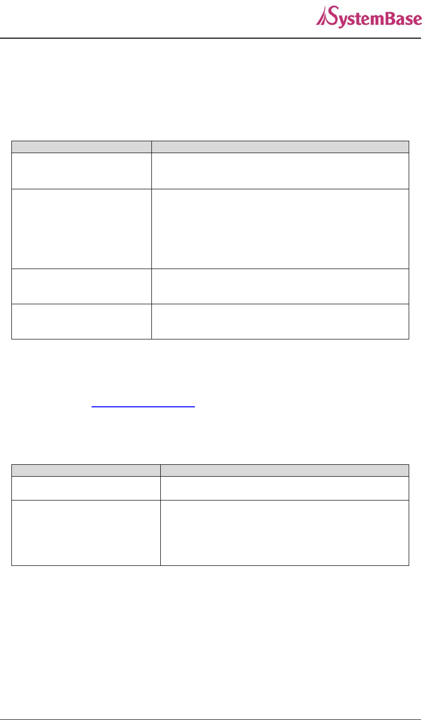
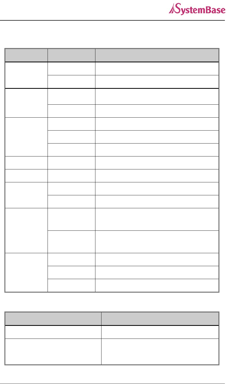
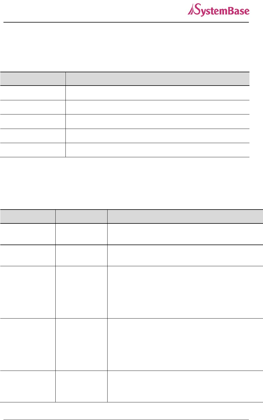
SerialGate Documents
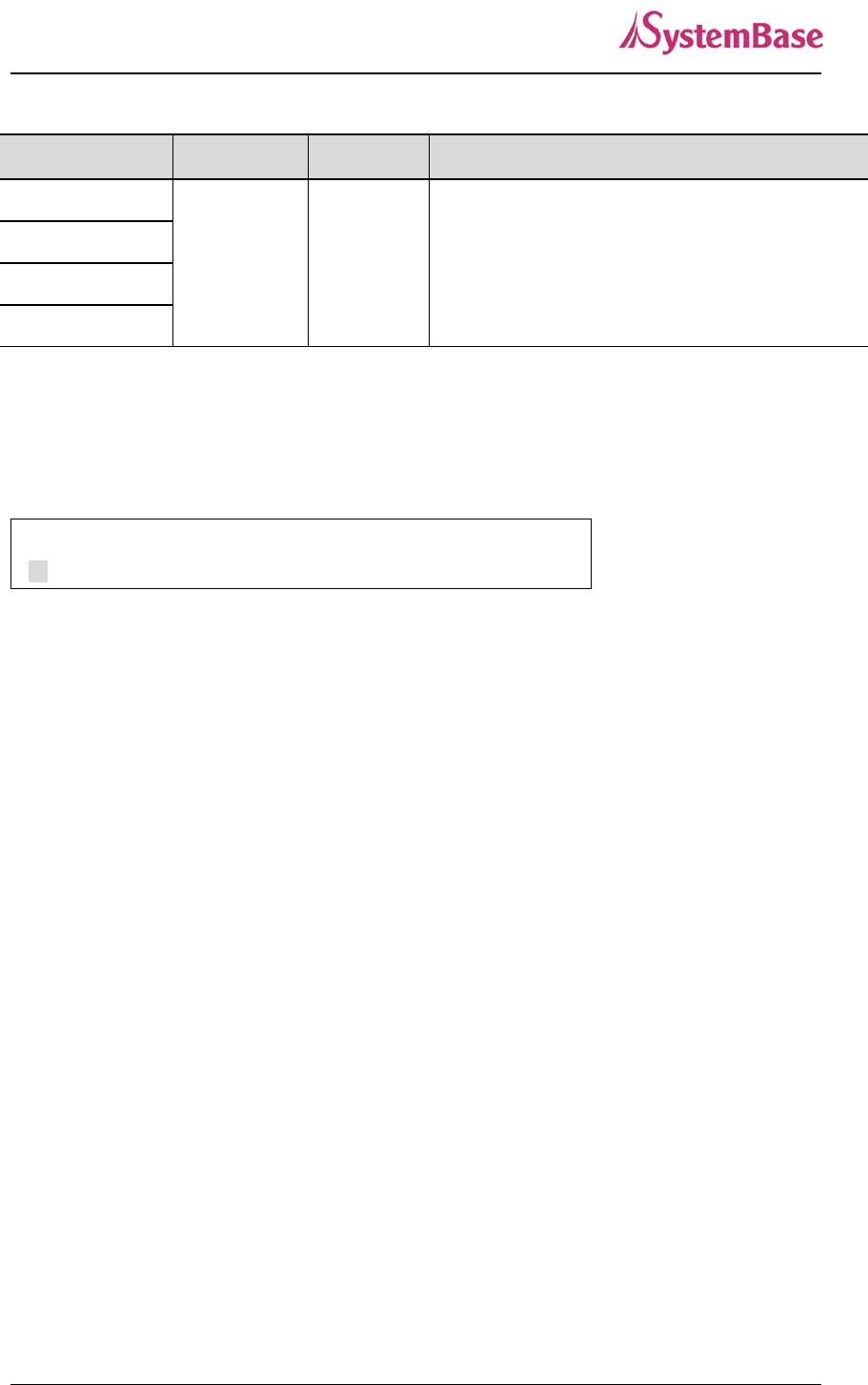
The following table summarizes documents included in the SerialGate document set.
Document Name Description
User Guide Integration, configuration, and management tasks are
explained for the administrator
Portview User Manual Guide for SystemBase device server management
application Portview
COM Port Redirector User
Manual Guide for SystemBase COM Port Redirector
TestView User Manual User Manual for testing Com port Redirector , TCP
Server/Client , UDP Server/Client
If you need brief information on SerialGate or device servers in general, please visit our
company website at http://www.sysbas.com/. You can view and/or download documents related
to SerialGate as well as latest software and firmware updates. Available resources are as
follows:
Document Name Description
SerialGate Spec Sheet Specifications for SerialGate products
SerialGate White Paper
An easy reading for anyone new to device server.
Deals with background and technology Past, present,
and future of device servers along with the overview
of market environment
All documents are updated promptly, so check for the recent document update. The contents in
these documents are subject to change without any notice in advance.

SerialGate User Guide
9
Technical Support
There are three ways you can get a technical support from SystemBase.
First, visit our website http://www.sysbas.com/ and go to ‘Technical Support’ menu. There you
can read FAQ and ask your own question as well.
Second, you can e-mail our technical support team. The mail address is tech@sysbas.com. Any
kind of inquiries, requests, and comments are welcome.
Lastly, you can call us at the customer center for immediate support. Our technical support team
will kindly help you get over with the problem. The number to call is 82-2-855-0501 (Extension
number 113). Do not forget to dial the extension number after getting a welcome message.

SerialGate User Guide
10
Ch.2 Getting Started
This chapter includes SerialGate overview, main and distinctive features, package contents for
each product, and application fields.
Overview
SerialGate provides network connectivity to various serial devices (security devices,
communication peripherals, modems, data printing devices, industrial metering devices, etc.).
SerialGate supports RS232, RS422, and RS485 serial communication standards under various
communication speed, meanwhile auto-sensing 100baseTX Fast Ethernet and 10baseT
Ethernet connection.
Features
Various features of SerialGate make it a universal yet distinctive device server solution. Here we
present main features of SerialGate. Others will explicitly appear throughout this guide.
- Max 921.6Kbps serial speed
- RS-232, Combo(RS-422/RS-485) or All version (RS232/422/485)
- 10/100Mbps Ethernet port
- COM Port Redirector for better adaptability
- Extensive configuration and monitoring with Portview
- Firmware update via Web and FTP
- Configuration using Web, Telnet, SNMP, and Portview
- SDK package which enables customizing program development provided

SerialGate User Guide
11
Package Component
SerialGate package is composed of the following components. Make sure every component is
included in your package. All packages include a module and a CD with utilities and documents.
SerialGate device 1pc (RS232 model or Combo(RS422/ RS485) model)
Direct LAN Cable 1pc
Power adapter 1pc (for SerialGate-1010/1020/1010 ALL/1020 ALL)
Power Cable 1pc (for SerialGate-1040/1080/1160)
CD (Manual and utilities)
A-Class Device
This device is registered only for office use, and both the seller and the user must be
aware of this. If not correctly sold or purchased, please exchange with home use
device.
SerialGate User Guide
12
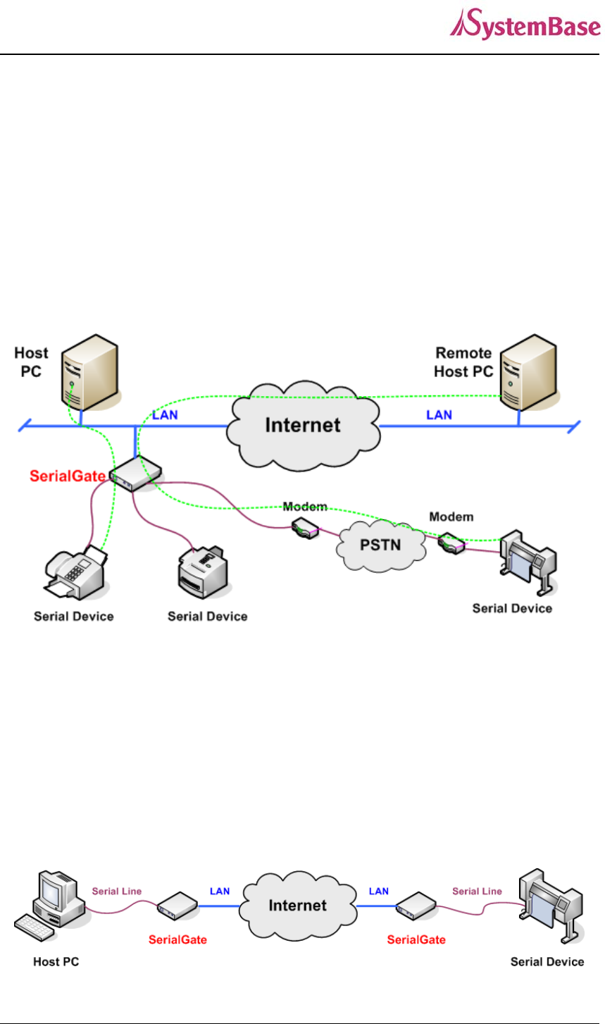
Application
SerialGate can be used in many practical applications in various fields. Here we present some
of them.
Network Serial Communication
PC and SerialGate are connected to the network, and a user gets an access to a device
connected to SerialGate on PC.
Serial Communication Tunneling
SerialGate enables a connection not restricted to distance between PC and serial device. To
enable this feature, a user should change its setting to TCP Server – TCP Client mode or UDP
Server – UDP Client mode referring to Chapter 5 of this manual. In this case, only data can be
transmitted while both data and control signal can be transmitted in Pair_Master and Pair_Slave
mode.
SerialGate User Guide
13
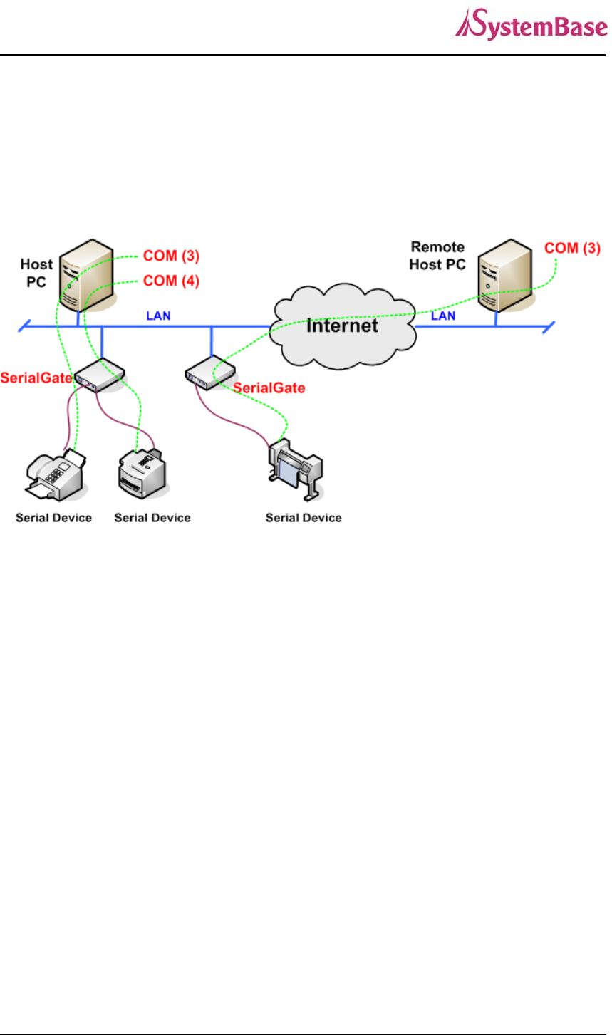
COM Port Redirection
With COM Port Redirection, a user can use serial port connected to SerialGate on the network
as if it is a serial port on PC.
Factory / Industrial Automation
PLC, Robot arms, Human-Machine Interface, Warehouse rails
Medical instruments, Inspection equipment controllers
Alarming units
Home Appliances / Electronic Devices
Power controller, Gaming machines
Scales, Gas detection units, Water & pollution metering devices
Data collection and distribution units
Financial / Building Automation
Card readers, Barcode scanners, Kiosks, Point-Of-Sale related devices
Serial printers, Cash registers, Credit card authorization terminals
Biometric detection units, Security devices
SerialGate User Guide
14
Ch 3. Hardware Description
This chapter provides SerialGate's hardware information including block diagram, layout, pin
specification, dimensions and other hardware-related issues.
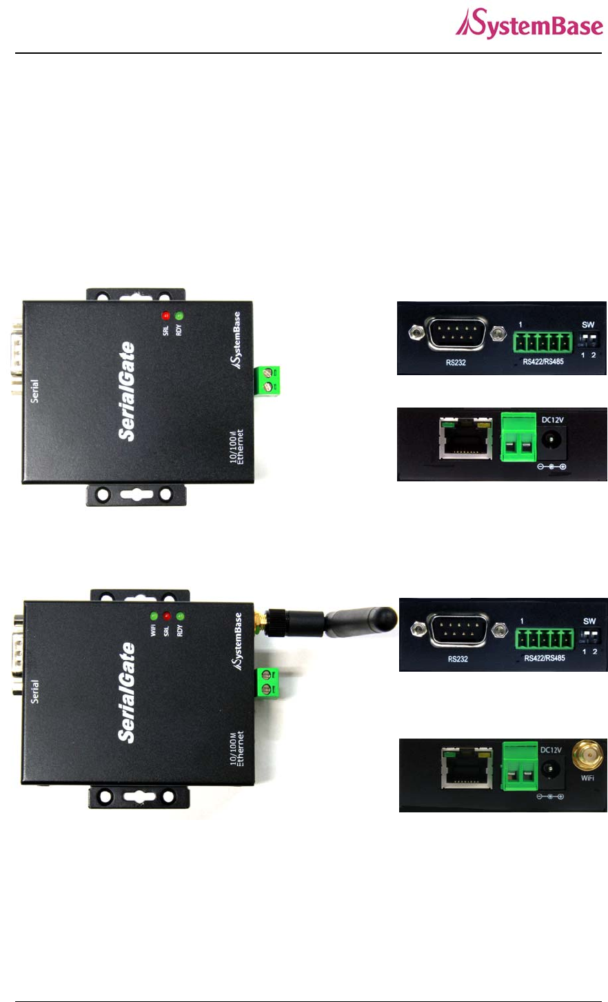
SerialGate-1010(W)/ALL Exterior
SerialGate-1010/ALL(Top)
SerialGate-
1010/ALL(Bottom)
SerialGate-1010/ALL
SerialGate-
1010W/ALL(Top)
SerialGate-
1010W/ALL(Bottom)
SerialGate-1010W/ALL
SerialGate User Guide
15
LED: Operation status of SerialGate. Next section describes the meaning of each
LED display status.
LAN port: 8-pin RJ45 jack which is used when connecting SerialGate to networking
devices such as Ethernet card, hub, and router.
Terminal block power connector: for connection of terminal block power cable
Power connector: for connection of DC 12V adapter cable
Serial: DB9 for RS232 and 5P Terminal Block for RS422/RS485
Termination Resistor Switch: Selection switch for termination resistor of RS422/485
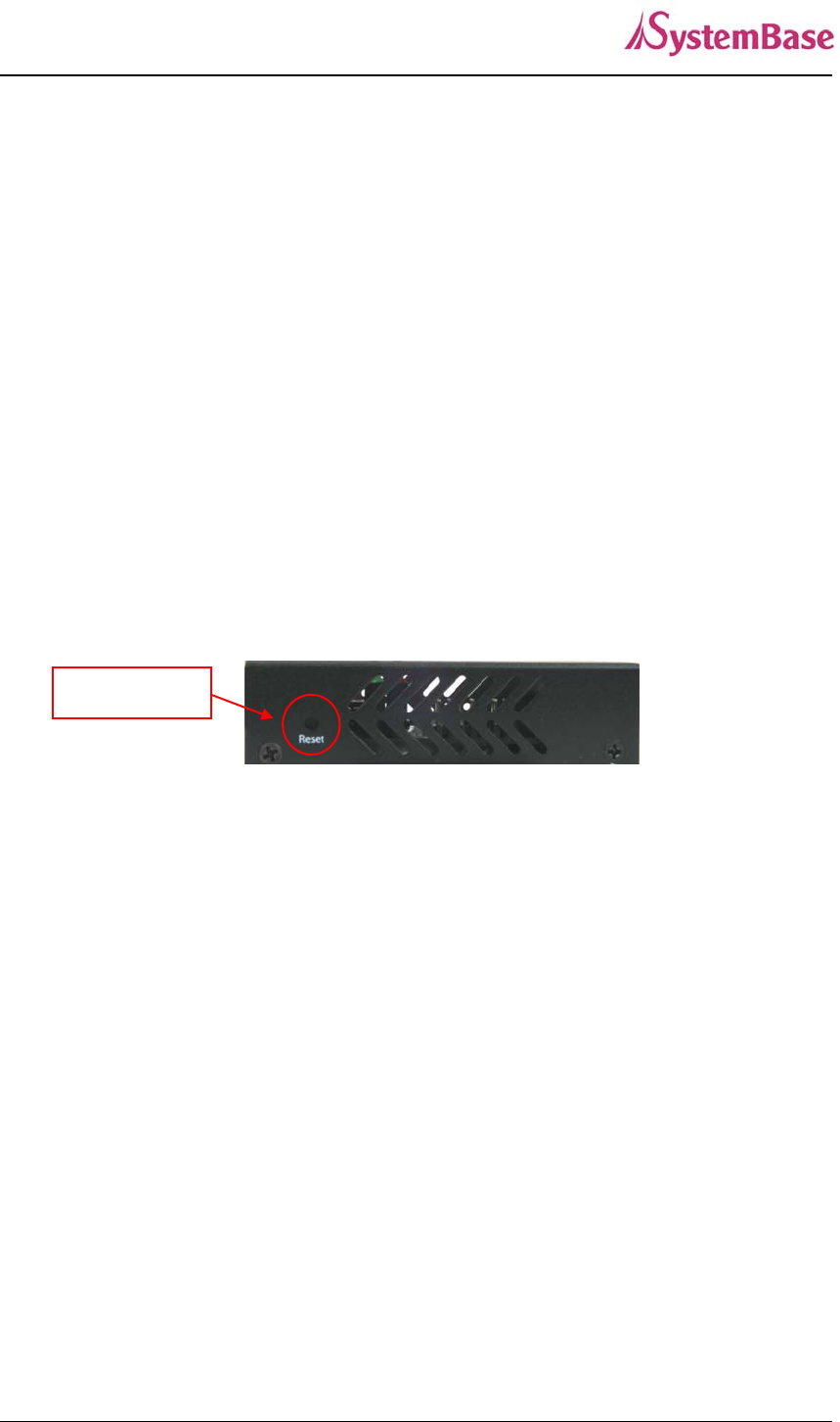
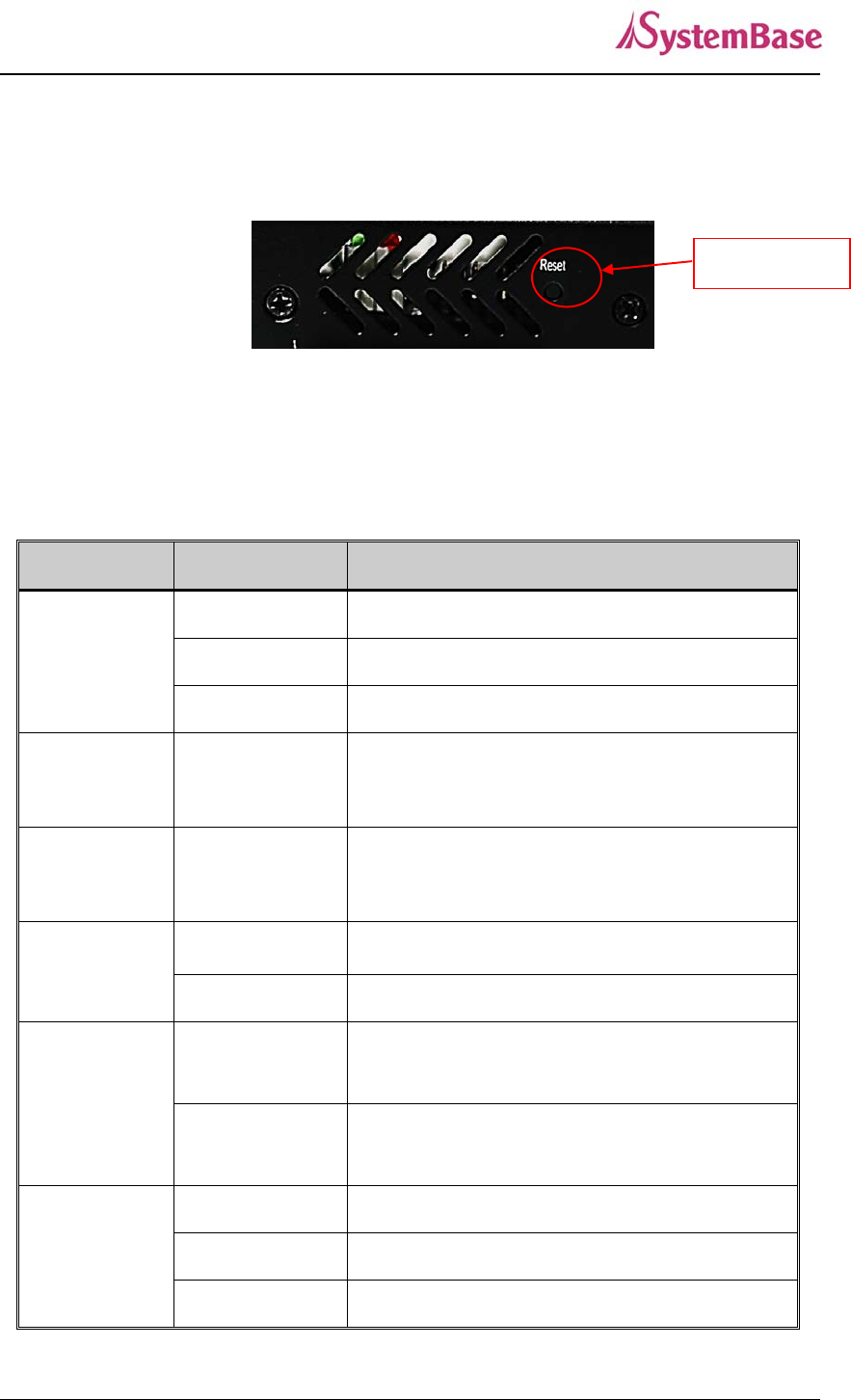
Reset: SerialGate reboots if this button is pressed for less than 3 seconds. If pressed
for longer than 3 seconds, SerialGate will restore factory default settings.
SerialGate-1010(W)/ALL (Left Side)
Reset Button
SerialGate User Guide
16
SerialGate-1010(W)/ALL LED / RESET
LED Status Meaning
RDY
(GREEN)
Blink Normal Operation
On Power supplied to the device
Off No power supplied to the device
SRL
(Red) Blink Serial data being transmitted
WIFI(Green) On WIFI Link up
Off WIFI Link down
LAN
(Right Orange)
On 100baseT connection detected & LAN data transf
erred
Off 10baseT connection detected & LAN data transfe
rred
LAN
(Left Green)
On Network connected
Off Network disconnected
Blink LAN data being transmitted
< Reset button features >
Operation Result
Pressed for less than 3 seconds Restart SerialGate
Pressed for more than 3 seconds Restore factory default settings of SerialGate,
and the device will automatically reboot.
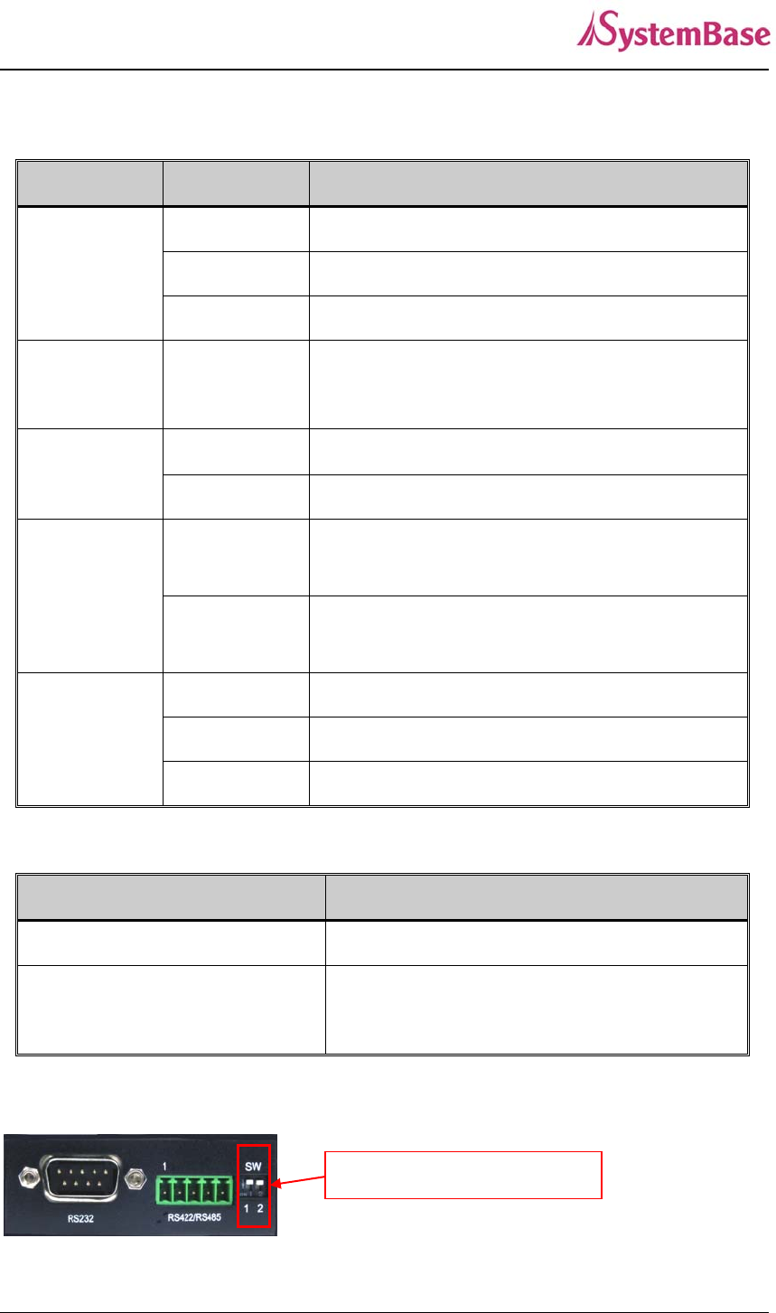
<RS-422/RS-485 Termination Resistor Setting>
Termination Resistor SW

SerialGate User Guide
17
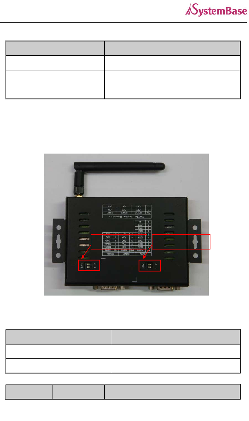
SerialGate-1010(W)/ALL(Bottom)
SW Status Meaning
1 On Activate TX / TRXD Resistor
Off Deactivate TX / TRXD Resistor
2 On Activate RX Resistor (RS-422 Only)
Off Deactivate RX Resistor (RS-422 Only)
SerialGate User Guide
18
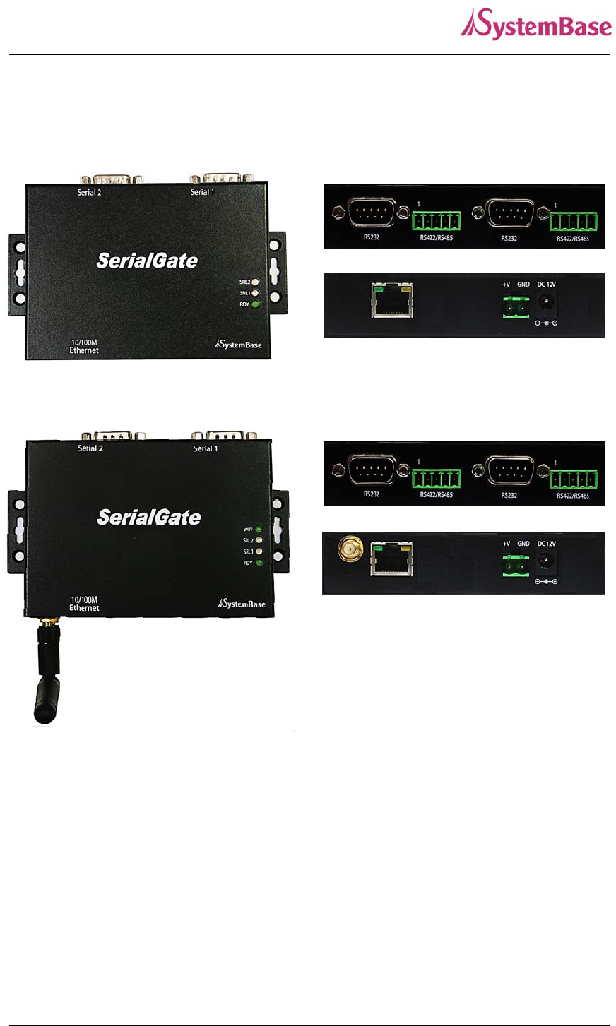
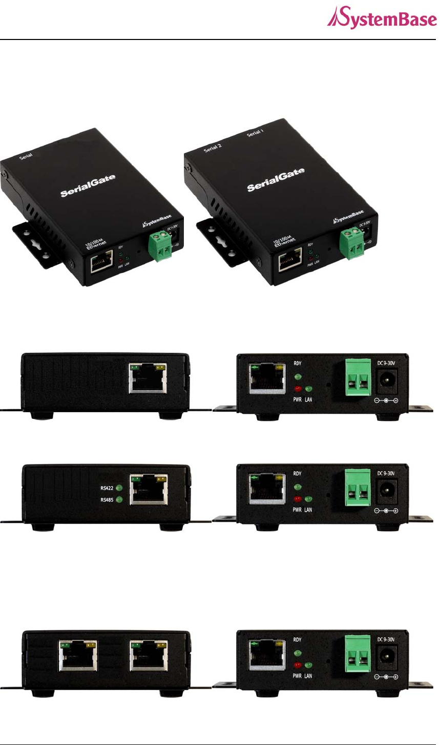
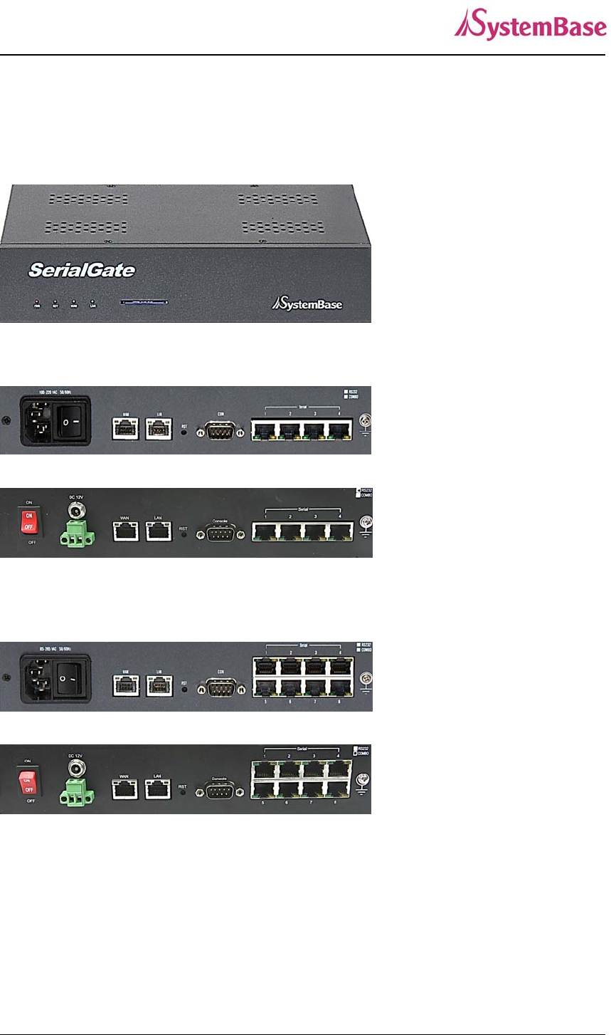
SerialGate-1020(W)/ALL Exterior
SerialGate-1020/ALL(Top)
SerialGate-1020/ALL(Bottom)
SerialGate-1020/ALL
SerialGate-1020W/ALL(Top)
SerialGate-1020W/ALL(Bottom)
SerialGate-1020W/ALL
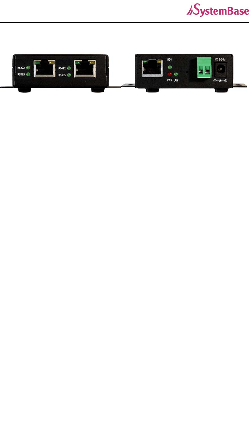
LED: Operation status of SerialGate. Next section describes the meaning of each
LED display status.
LAN port: 8-pin RJ45 jack which is used when connecting SerialGate to networking
devices such as Ethernet card, hub, and router.
Terminal block power connector: for connection of terminal block power cable
Power connector: for connection of DC 12V adapter cable
Serial: DB9 for RS232 and 5P Terminal Block for RS422/RS485
SerialGate User Guide
19
Termination Resistor Switch: Selection switch for termination resistor of RS422/485
Reset: SerialGate reboots if this button is pressed for less than 3 seconds. If pressed
for longer than 3 seconds, SerialGate will restore factory default settings.
SerialGate-1020(W)/ALL(Left Side)
SerialGate-1020(W)/ALL LED / RESET
LED Status Meaning
RDY
(GREEN)
Blink Normal Operation
On Power supplied to the device
Off No power supplied to the device
SRL1
(Red) Blink Serial #1 data being transmitted
SRL2
(Red) Blink Serial #2 data being transmitted
WIFI(Green) On WIFI Link up
Off WIFI Link down
LAN
(Right Orange)
On 100baseT connection detected & LAN data tran
sferred
Off 10baseT connection detected & LAN data trans
ferred
LAN
(Left Green)
On Network connected
Off Network disconnected
Blink LAN data being transmitted
Reset Button
SerialGate User Guide
20
< Reset button features >
Operation Result
Pressed for less than 3 seconds Restart SerialGate
Pressed for more than 3 seconds Restore factory default settings of SerialGate,
and the device will automatically reboot.
<RS-422/RS-485 Termination Resistor Setting>
SerialGate-1020(W)/ALL(Bottom)
SW Meaning
SW1 Resistor for Serial Port #1
SW2 Resistor for Serial Port #2
SW Status Meaning
Termination SW1 Termination SW2

SerialGate User Guide
21
1 On Activate TX / TRXD Resistor
Off Deactivate TX / TRXD Resistor
2 On Activate RX Resistor (RS-422 Only)
Off Deactivate RX Resistor (RS-422 Only)
SerialGate User Guide
22
SerialGate-1010/1020 Exterior
SerialGate-1010 SerialGate-1020
SerialGate-1010 (RS232 Version)
SerialGate-1010 (Combo Version)
SerialGate-1020 (RS232 Version)
SerialGate User Guide
23
SerialGate-1020 (Combo Version)
Power connector: for connection of DC9~30V adapter cable
Terminal block power connector: for connection of terminal block power cable
Reset button: SerialGate reboots if this button is pressed for less than 3 seconds. If
pressed for longer than 3 seconds, SerialGate will restore its factory default settings.
LED: Operation status of SerialGate. Next section describes the meaning of each LED
display status.
LAN port: 8-pin RJ45 jack connects SerialGate to networking devices such as Ethernet
card, hub, and router.
Serial: RJ-45 socket for serial ports (RS-232, or Combo(RS-422/RS-485))
SerialGate User Guide
24
SerialGate-1010/1020 LED / RESET
LED Status Meaning
PWR
(Red)
On Power supplied to the device
Off No power supplied to the device
LAN
(Green)
Off No active network connection
On Network activated
RDY
(Red)
Blink Normal operation
On System Booting
Off System Error
RS422 On
Serial port set to RS422 mode (Combo model)
RS485 On
Serial port set to RS485 mode (Combo model)
Serial Tx/Rx
Green Blink Serial data transmitted
Orange Blink Serial data received
LAN Port
(Left Green)
On 100baseT connection detected & LAN data tran
sferred
Off 10baseT connection detected & LAN data trans
ferred
LAN Port
(Right Orange)
On Network connected
Off Network disconnected
Blink LAN data being transmitted
< Reset button features >
Operation Result
Pressed for less than 3 seconds Restart SerialGate
Pressed for more than 3 seconds Restore factory default settings of SerialGat
e, and the device will automatically reboot.
SerialGate User Guide
25
SerialGate-1040/1080 Exterior
SerialGate-1040/1080 (Front)
SerialGate-1040 (RS232/Combo Version)
AC Version
DC Version
SerialGate-1080 (RS232/Combo Version)
AC Version
DC Version
Serial: RJ-45 socket for serial ports (RS-232, or Combo(RS-422/RS-485))
Power connector
AC Version : for connection of AC100~245V cable

SerialGate User Guide
26
DC Version : for connection of DC12V adapter cable
and for connection of terminal block power cable
Reset: SerialGate reboots if this button is pressed for less than 3 seconds. If pressed for
longer than 3 seconds, SerialGate will restore factory default settings.
LED: Operation status of SerialGate. Next section describes the meaning of each LED
display status.
WAN: Main network port used when connecting SerialGate to networking devices such
as Ethernet card, hub, and router.
LAN: Sub-network port used as DHCP Server. Assigns IP address to a device connected to
sub-network.
SD / MMC: SD memory card works for system log. Available up to 32 Gbytes. (SD memory
not included in the package)
SerialGate-1040/1080 LED / RESET
<LED Feature>
LED Status Meaning
PWR
(RED)
On Power supplied to the device
Off No power supplied to the device
RDY
(Green)
Blink Normal operation
On System Booting
Off System Error
WAN
(Green)
Off Deactivate main network
On Activate main network
LAN
(Green)
Off Deactivate sub network
On Activate sub network
Serial Tx/Rx
(Green/Orange)
Blink Serial data transmitted
Blink Serial data received
WAN/LAN On
100baseT connection detected & LAN data transf
erred

SerialGate User Guide
27
(Left Green) Off 10baseT connection detected & LAN data transfe
rred
WAN/LAN
(Right Orange)
On Connected to network
Off Disconnected to network
Blink LAN data being transmitted
< Reset button features >
Operation Result
Pressed for less than 3 seconds Restart SerialGate
Pressed for more than 3 seconds Restore factory default settings of SerialGate,
and the device will automatically reboot.
SerialGate User Guide
28
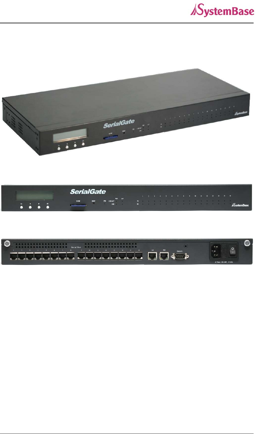
SerialGate-1160 Exterior
Serial: RJ-45 socket for serial ports (RS232, 422,485). A user can select protocol in web
browser.
Power connector: for connection of 100 ~ 245 VAC cable
Reset: SerialGate reboots if this button is pressed for less than 3 seconds. If pressed for
longer than 3 seconds, SerialGate will restore factory default settings.
LED: Operation status of SerialGate. Next section describes the meaning of each LED
display status.
WAN: Main network port used when connecting SerialGate to networking devices such
as Ethernet card, hub, and router.
LAN: Sub-network port used as DHCP Server. Assigns IP address to a device connected to
sub-network.
SerialGate User Guide
29
SD / MMC: SD memory card works for system log. Available up to 32 Gbytes. (SD memory
not included in the package)
LCD: CLCD (16 * 2 line). Configuration and monitoring SerialGate via LCD.
LCD Button: Composed of 4 keys to control LCD. (Esc, Enter, Left, Right)
SerialGate-1160 LED / RESET
<LED feature>
LED Status Meaning
PWR
(WHITE)
On Power supplied to the device
Off No power supplied to the device
WAN/LAN
(Green)
On Connected to network
Off Disconnected to network
Blink LAN data being transmitted
WAN/LAN
(Orange)
On 100baseT connection detected & LAN data tran
sferred
Off 10baseT connection detected & LAN data trans
ferred
Serial Tx
(Green) Blink Serial data transmitted
Serial Rx
(Orange) Blink Serial data received
< Reset button features >
Operation Result
Pressed for less than 3 seconds Restart SerialGate
Pressed for more than 3 seconds Restore factory default settings of SerialGate,
and the device will automatically reboot.
SerialGate User Guide
30
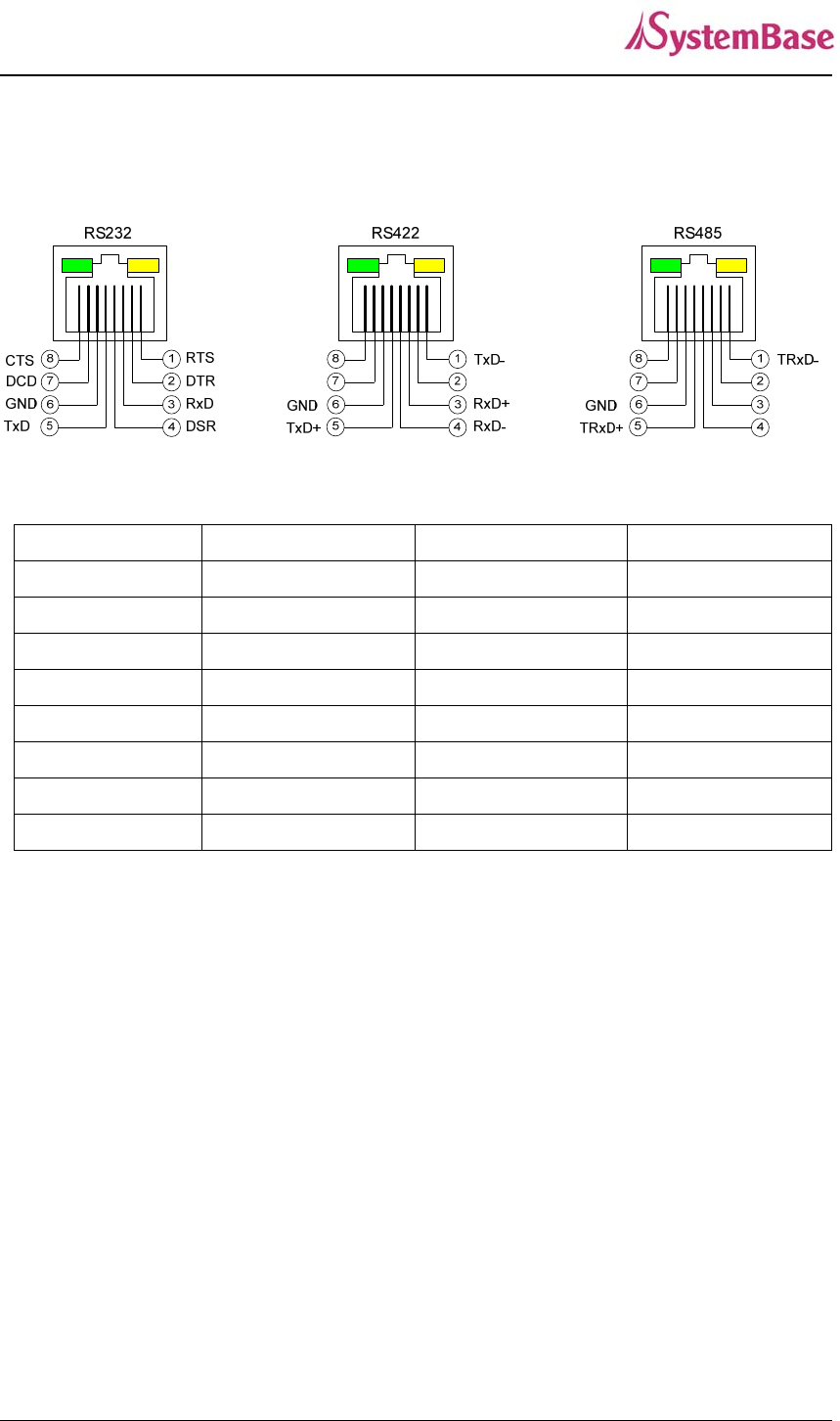
Pin Specification (SerialGate-1010/1020/1040/1080)
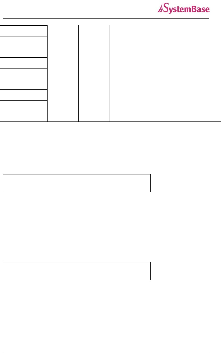
RS-232 RS-422 RS-485
1 RTS TxD - TRxD -
2 DTR - -
3 RxD RxD + -
4 DSR RxD - -
5 TxD TxD + TRxD +
6 GND GND GND
7 DCD - -
8 CTS - -
SerialGate User Guide
31
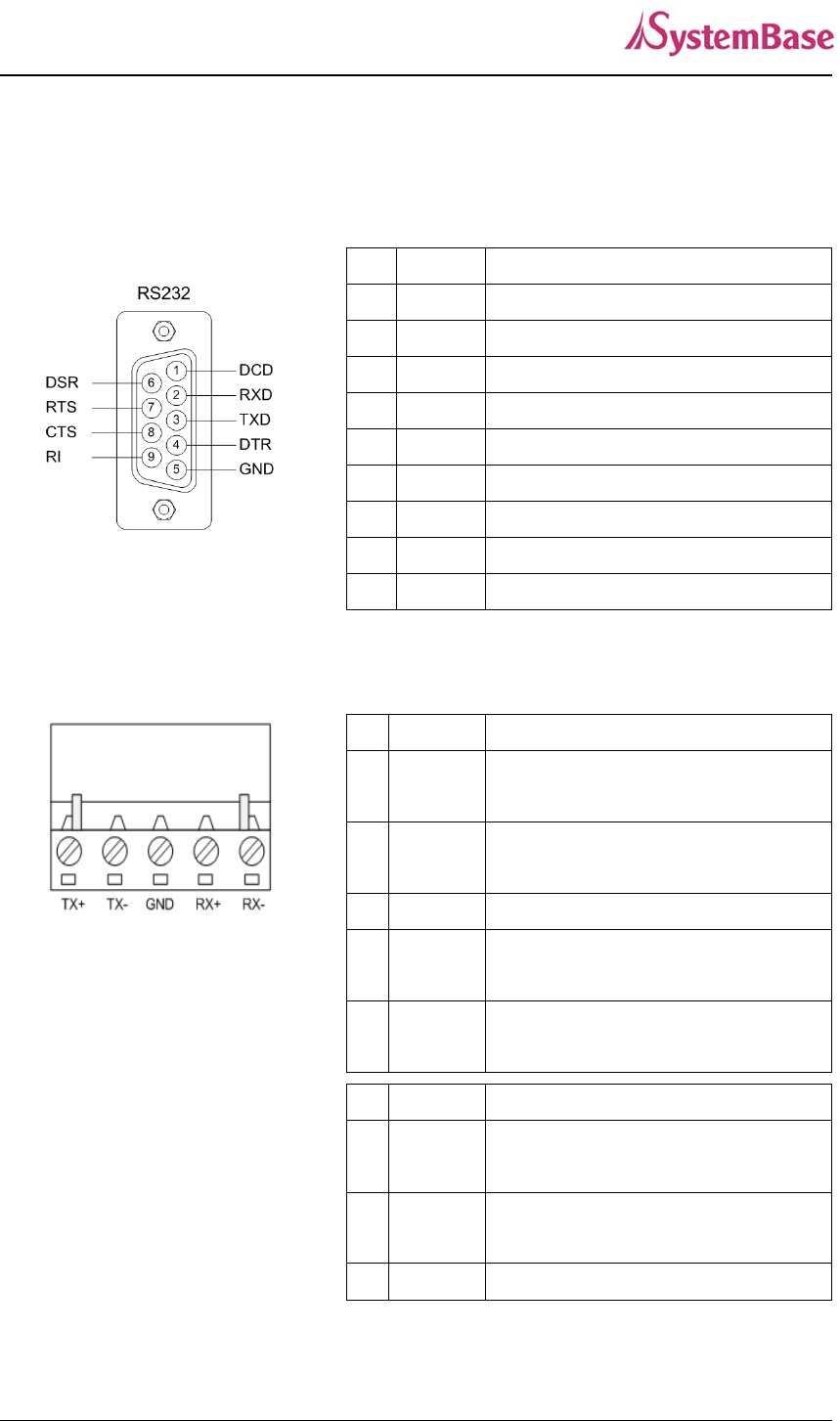
Pin Specification (SerialGate-1010(W)/ALL, SerialGate-1020(W)/ALL)
RS232
`
RS422 Full Duplex
1 2 3 4 5
R
S485 Half Duplex
Signal Description
1 DCD Data Carrier Detection (Input)
2 RXD Receive Data (Input)
3 TXD Transmit Data (Output)
4 DTR Data Terminal Ready (Output)
5 GND Ground
6 DSR Data Set Ready (input)
7 RTS Request to Send (Output)
8 CTS Clear to Send (Input)
9 RI Ring Indicator (Input)
Signal Description
1TXD+
Transmit differential data positive
(Output)
2TXD-
Transmit differential data negative
(Output)
3 GND Ground
4RXD+
Receive differential data positive
(Input)
5RXD-
Receive differential data negative
(input)
Signal Description
1TRXD+
Transmit/Receive differential data
positive
2TRXD-
Transmit/Receive differential data
negative
3 GND Ground
SerialGate User Guide
32
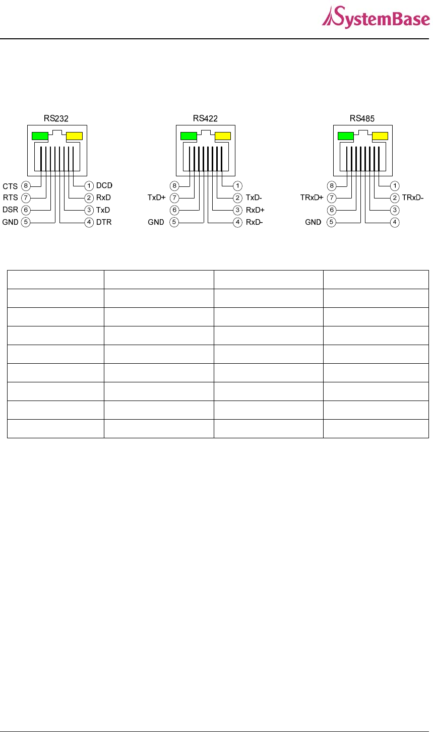
Pin Specification (SerialGate-1160)
RS-232 RS-422 RS-485
1 DCD - -
2 RxD TxD - TRxD -
3 TxD RxD + -
4 DTR RxD - -
5 GND GND GND
6 DSR - -
7 RTS TxD + TRxD +
8 CTS - -

SerialGate User Guide
33
Ch. 4 Installation
This chapter explains how to install SerialGate. It deals with LAN and serial connection guides
for SerialGate to operate together with the target serial device.
Connection Guide
In order to connect SerialGate to network, you need to use RJ45 Ethernet port. It supports both
10Mbps and 100Mbps Ethernet connection (auto-sensing). Since SerialGate’s WAN/LAN port
supports MDIX, it automatically detects any kind of cable. (Cross or direct LAN cable) Plug one
end of a LAN cable to SerialGate and the other end to a hub, switch, or any other network
device.
First-Time Bootup
First of all, please make sure that the power input you supply to the module is corresponding with the
SerialGate model that you have. If an appropriate power input has been successfully supplied,
SerialGate will power on and start booting.
Although there is no power LED to check the status, you can check by LEDs on the RJ45 Ethernet port.
LED status operation is described in Chapter 3. Hardware Description.
An IP address is required to access SerialGate’s web interface or telnet command-line configuration
tool. By factory default, a static IP address is assigned to SerialGate. After the initial connection, you
can either manually assign a different IP address or set SerialGate to automatically get an IP address
from a DHCP server. While this depends on your network environment and policy, it is strongly
recommended that a user assigns SerialGate with a unique static IP.
Connecting to SerialGate
In order to view current SerialGate’s settings or modify them, you need to make a Web or Telnet
connection to SerialGate. IP address is required information to make a connection.
There are two ways you can know the current IP address of Eddy.
SerialGate User Guide
34
If SerialGate’s WAN port uses assigned IP address from DHCP server or is set to a fixed IP address,
SerialGate supports the following options in case that a user does not know IP address.
For SerialGate-1010/1020, SerialGate-1010(W)/ALL, SerialGate-1020(W)/All
1. A user can connect to SerialGate LAN port’s virtual IP address; “10.10.1.1”
2. A user can search IP address pre-set to SerialGate using “Detector” application enclosed in Utility &
Documents CD and connect to SerialGate.
For SerialGate-1040/1080/1160
1. A user can connect to SerialGate LAN port’s default IP address; “10.10.1.1”.
2. Connecting a serial console port to a PC’s serial port, a user can set 115,200bps and connect to a
SerialGate.
3. A user can search IP address pre-set to SerialGate using “Detector” application enclosed in Utility &
Documents CD and connect to SerialGate.
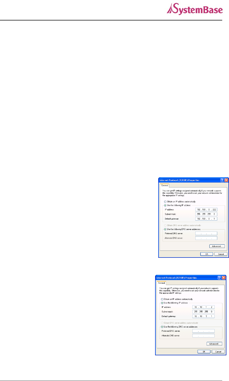
WAN Default IP address: 192.168.0.223
SerialGate’s default IP address is set to 192.168.0.223. In order to
connect with this address, you need to change network configurations
so that your PC can connect to the IP 192.168.0.223. Please refer to
an example below, and note that values don’t necessarily have to be
identical to the example below.
LAN Sub IP address: 10.10.1.1
For SerialGate-1010/1020, LAN port’s virtual IP address is 10.10.1.1
while LAN port’s default IP address for SeroalGate-1040/1080/1160 is
10.10.1.1. In order to connect with this address, you need to change
network configurations so that your PC can connect to the IP
10.10.1.1. Please refer to an example below, and note that values
don’t necessarily have to be identical to the example below.
SerialGate User Guide
35
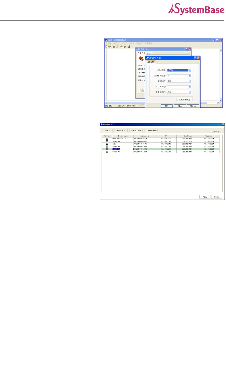
Serial Console Port
SerialGate-1040/1080/1160 supports console
port. If a user connects console port and a
PC’s serial port with a serial cable, and run
communication program such as
hyperterminal, a user can make a
configuration as 115200 bps, None Parity, 8
Data bits, 1 Stop Bit and connect to a device.
Connection via portview
By running the portview program in the
Utility & Documents CD included in the
SerialGate package, you can dynamically
search all SerialGates on the network and
connect to any of them. (For more
information on portview, please refer to the
Portview manual in the Utility & Documents
CD included in the SerialGate package)
After running portview, click Search button.
You can view the list that is running in your network. Select the module that you would make a
connection to, and click Telnet or Web to connect to the device via Telnet or Web, respectively.
you can modify and apply the IP address of serialgate via this program.
Now, you are ready to connect to SerialGate! There are three options to configure SerialGate.
1) Configuration via Web
A user can easily configure SerialGate with web interface, accessible from any web browser. For more
information, please refer to Chapter 5. Configuration via Web.
2) Configuration via Telnet
A user can configure SerialGate with commands after accessing SerialGate through Telnet. For more
information, please refer to Chapter 6. Configuration via Telnet.
3) Configuration via Portview
A user can use a Windows-based utility Portview from SystemBase to monitor SerialGate. For more
information on using the utility for your administration purpose, please refer to Portview User Guide.
SerialGate User Guide
36
Ch. 5 Configuration via Web
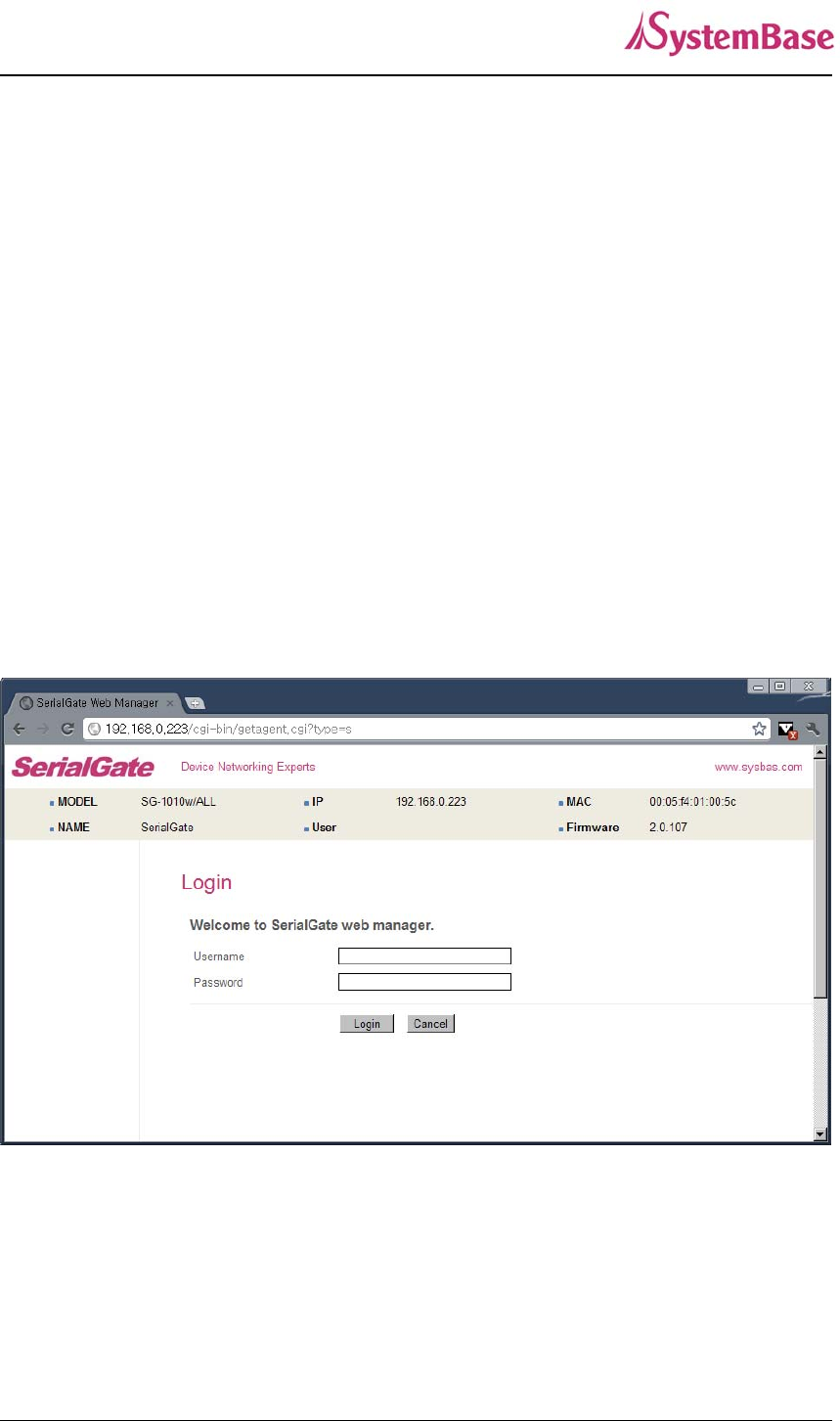
Connection
Open web browser and enter the IP address of SerialGate to access SerialGate’s web manager.
Once you are successfully connected, the following page will show up. You need to enter
appropriate username and password to login. Please note that this username and password are
used as authentication method for Telnet as well. This means if username or/and password has
been modified from the web interface, modified values have to be entered to connect to Telnet,
and vice versa.
Factory default username: serialgate
Factory default password: 99999999
SerialGate User Guide
37
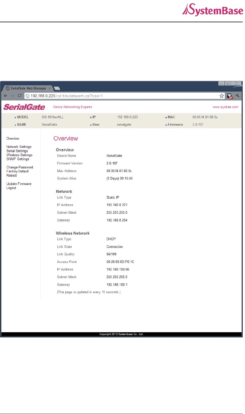
Setup Menu
If login process is successful, you will see a web manager’s main page, showing summary of
your device. On the left, you will see a setup menu, and you can navigate through these options.
SerialGate User Guide
38
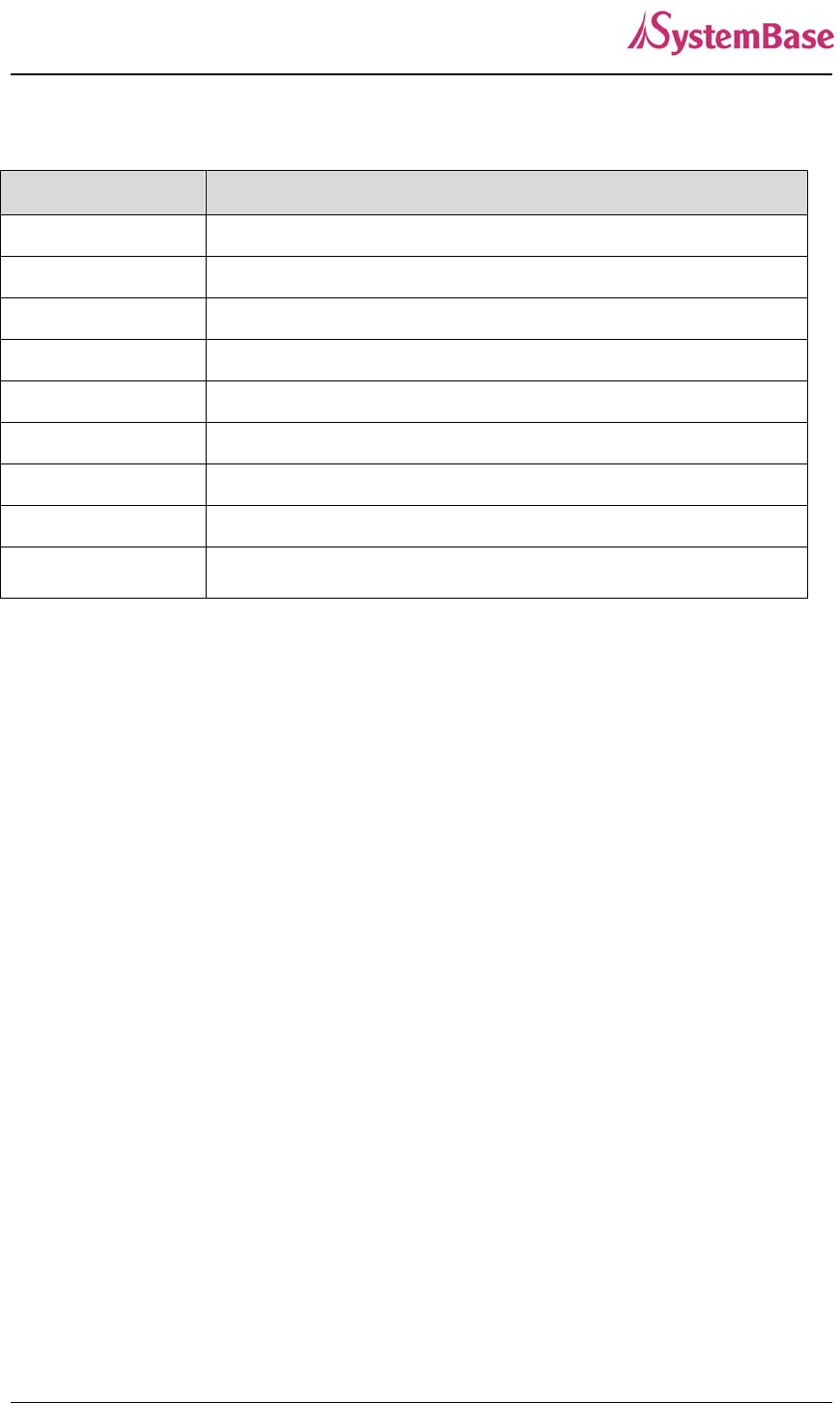
The followings are main features of Setup Menu.
Menu Description
Summary Confirm basic information about SerialGate
Network Settings Configure network connection settings.
Serial Settings Configure detailed operation environment for serial communication
SNMP Settings Configure detailed operation environment for SNMP
Change Password Change ID and password for both Web and Telnet interface
Update Firmware Update SerialGate’s firmware
Factory Default Restore all the factory default settings.
Save & Reboot Save the configurations and reboot SerialGate
System Log View system log of SerialGate (SerialGate-1040/1080/1160)
SerialGate User Guide
39
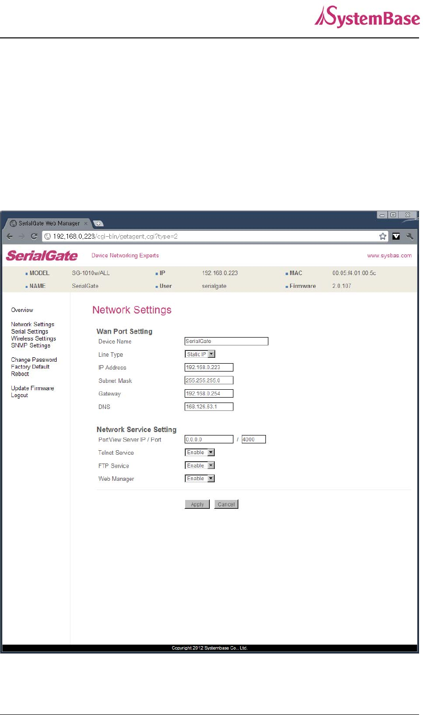
Network Settings
In Network Settings, a user can configure general network environment and network
management.
After changing values, you need to click ‘Apply’ button. If you don’t want to change, you need to
click ‘Cancel’ button. If you change the IP address, you must reconnect via changed IP address.
SerialGate-1010/1020/1010(W) ALL/1020(W) ALL
SerialGate User Guide
40
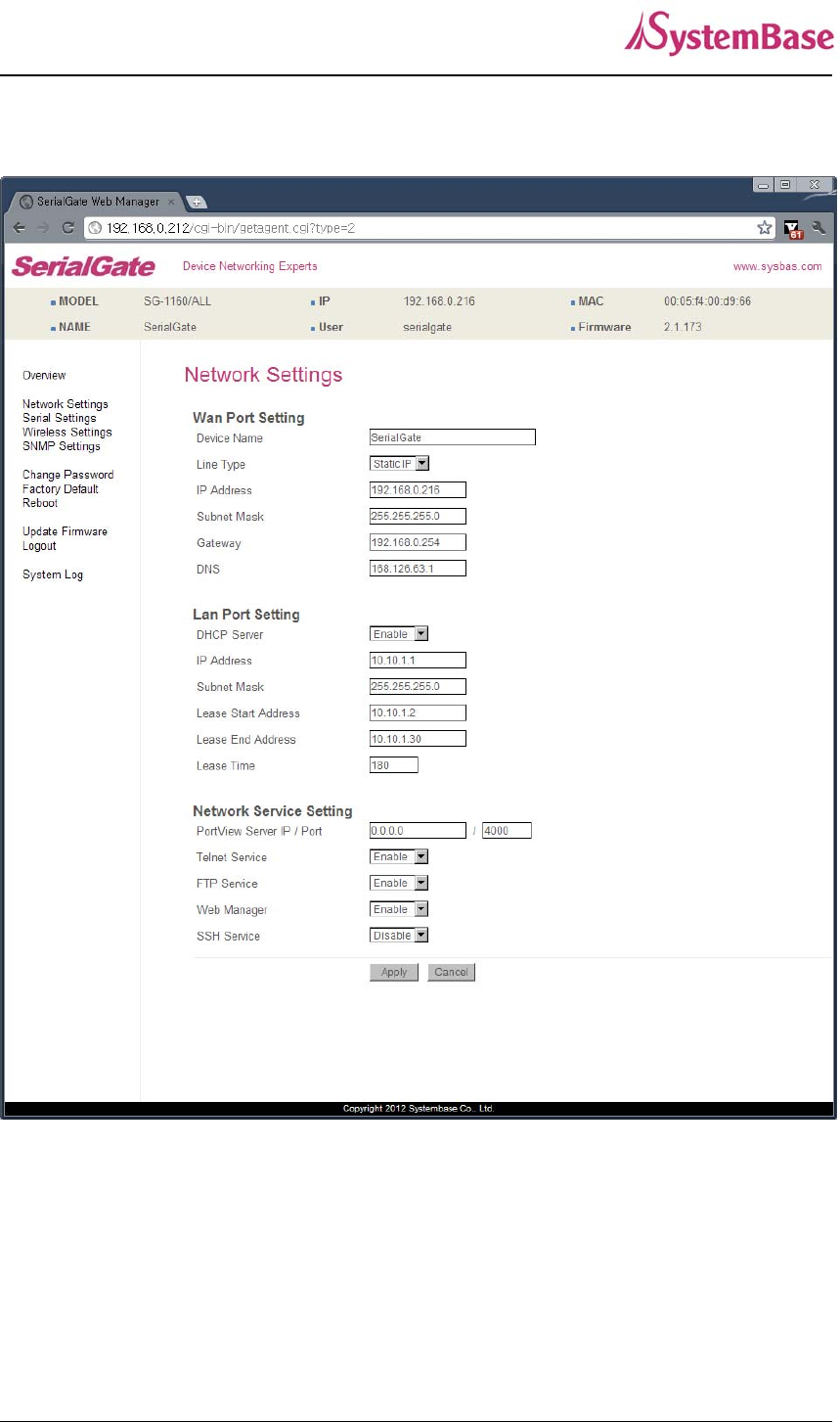
SerialGate-1040/1080/1160
SerialGate User Guide
41
The followings are main features of WAN Configuration.
Menu Default Description
Device
Name SerialGate Name of the current device
Line Type Static IP IP obtaining method for SerialGate’s network connection.
IP Address 192.168.0.22
3
Current IP address SerialGate is assigned to.
(When line type is Static IP, manually enter an appropriate IP
address. When line type is DHCP, current IP is displayed, but it
is not editable.)
Subnet
Mask
255.255.255.
0
Current subnet mask SerialGate is assigned to.
(When line type is Static IP, manually enter an appropriate
subnet mask. When line type is DHCP, current subnet mask is
displayed, but it is not editable.)
Gateway 192.168.0.25
4
Current default gateway SerialGate is assigned to
(When line type is Static IP, manually enter an appropriate
default gateway. When line type is DHCP, current default
gateway is displayed, but it is not editable.)..
DNS 168.126.63.1 Domain Name Service IP address
For SerialGate-1040/1080/1160, the main features of LAN Configuration are as follows.
Menu Default Description
DHCP Server Enable Enable or disable DHCP server.
IP Address 10.10.1.1 Set the current IP address
Subnet Mask 255.255.255.
0 Set Subnet Mask address
Lease Start
Address 10.10.1.2 If DHCP server is enabled, start address of the DHCP scope
for leasing.
Lease End
Address 10.10.1.30 If DHCP server is enabled, end address of the DHCP scope
for leasing.
Lease Time 180 IP address lease time

SerialGate User Guide
42
Main features for Network Service Configuration are as follows.
Menu Default Descriptions
PortView
IP / Port 0.0.0.0 / 4000
Set the IP address and the socket number of the PC where
Portview is installed. For more information about Portview,
please refer to the Portview User Manual.
If IP is set to 0.0.0.0, this feature is disabled
Telnet
Service Enable Enable or disable Telnet service.
If disabled, you cannot connect to SerialGate via Telnet.
FTP
Service Enable Enable or disable FTP service.
If disabled, you cannot connect to SerialGate via FTP.
WEB
Service Enable Enable or disable Web service.
If disabled, you cannot connect to SerialGate via Web.
SSH
Service Disable Enable or disable Secure Shell service.
SerialGate User Guide
43
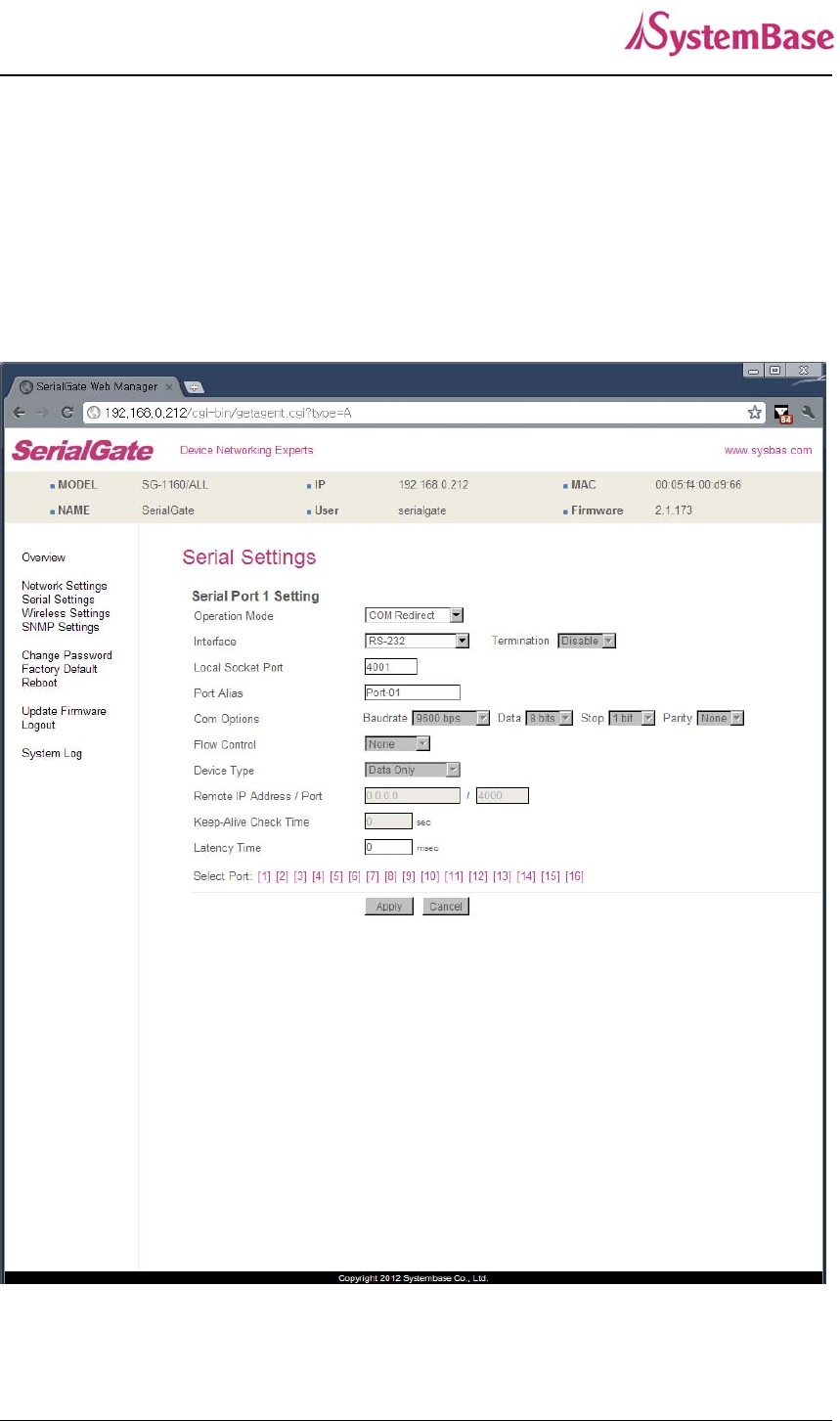
Serial Settings
A user can set the communication and operation environment for the serial port.
After changing values, you need to click ‘Apply’ button. If you don’t want to change, you need to
click ‘Cancel’ button.

SerialGate User Guide
44
Serial settings for SerialGate are as follows.
Menu Default Descriptions
Operation
Mode COM
Select the operation protocol that will be applied in the serial port.
Disable
Disable the serial port.
COM Redirector
Use the serial port of SerialGate as a virtual COM port in Windows
2000/XP/2003/Vista.
TCP Server
SerialGate works as a socket server, waiting for the client connection
on the network. Socket number for awaiting connections can be set
in ‘Local socket port’ field. After socket connection, data between
socket and serial port will be transmitted.
TCP Client
SerialGate acts as a socket client in this mode. It tries to connect to
the server IP address and the socket number assigned when a
certain server waits for connection on the network.
All data between the socket and the serial port is transferred
untouched after the socket connection is established.
TCP Broadcast
SerialGate works as a server, accepting up to 5 simultaneous
connections from socket clients. Data transmitted from SerialGate is
broadcast to each socket client.
TCP Multiplex
SerialGate works as a server, accepting up to 5 simultaneous
connections from socket clients. The difference between TCP
Broadcast and TCP Multiplex is that Multiplex allows each socket to
communicate exclusively. That is, serial data in response are only
transferred to the sender socket.
UDP Server
SerialGate works as a UDP server, waiting for UDP connection from
the client on the network.
Socket number for awaiting connections can be set in ‘Local socket

SerialGate User Guide
45
Menu Default Descriptions
port’ field.
Once a UDP packet is received to the socket that waits for the
connection, the data is transmitted to the serial port. The data input
from the serial port is put into UDP packets, which eventually are
sent to the client.
UDP Client
When the data is input to the serial port, UDP packets are sent using
the preset IP address and the socket number of the server.
Pair_Master/ Pair_Slave
It extends a serial cable between DTE and DCE to network, and
enables communication not limited to distance. Two devices are
required for this feature and set one to Pair_master and another to
Pair_Slave. It can be used for serial communication tunneling.
MODBUS ASCII
Connect MODBUS/ASCII SLAVE using serial port and make user of
MODBUS/TCP MASTER feature using LAN port in PC. This feature
enables MODBUS media converter function. (Available for
SerialGate-1010/ALL).
User Application
A user can run own customized program. In order to run it, a user
needs to ask for application development environment to
SystemBase.
Interface
RS232,
RS422
RS485
RS232 model is set to RS232.
Combo model is selectable between RS422, RS485(No-Echo) and
RS485(Echo). Default value is RS422.
All model is selectable between RS232, RS422, RS485(No-Echo)
and RS485(Echo). Default value is RS232.
SerialGate-1160 model is selectable between RS232, RS422,
RS485(No-Echo) and RS485(Echo). Default value is RS232. and
termination can be configured.
Local
Socket
Port
4001
Set the socket number for the port. TCP server and UDP server
operation mode makes use of this port for awaiting network socket
connections.
Port Alias Port1 Name each port for convenience. 16 Characters at maximum.

SerialGate User Guide
46
Menu Default Descriptions
Baud
Rate 9600 bps
Set communication speed.
(Options: 150, 300, 600, 1200, 2400, 4800, 9600, 19200, 38400,
57600, 115200, 230400, 460800, 921600 bps)
Data Bits 8 Set the number of bits in each character size.
(Options: 5, 6, 7, 8)
Stop Bits 1 Set the number of stop bits..
(Options: 1, 2)
Parity None Set parity bit check scheme..
(Options: None, Odd, Even)
Flow
Control None Set the flow control scheme.
(Options: None, Xon/Xoff, RTS/CTS)
Device
Type DataOnly
Set the signal line checking method for the device to be connected to
the given serial port.
If the mode is set to Data Only, only TxD, RxD, and GND signal lines
are used in inter-device communication.
If the mode is set to Modem Signals, all modem signals except
RI(Ring Indicator) are asserted, tested, and used in communication.
(Options: Data Only, Modem Signals)
Remote
IP
Address /
Port
0.0.0.0 /
4000
If the Operation Mode is in TCP Client or UDP Client or Pair_Master
mode, set the IP address and the socket number to connect to.

SerialGate User Guide
47
Menu Default Descriptions
Keepalive
Check
Time
0
After a certain amount of time passes without any communication
after the socket connection between the given serial port and the
server is established, automatically disconnect the socket
connection. Valid from 0 to 32767 sec.
For example, if the operation mode is set to TCP Server and Alive
Check Time is configured to 10, TCP Server will listen for the client’s
connection and eventually establish a connection. Since the check
time is 10 seconds, the server will wait for 10 seconds until the client
connected to it sends any packet. If there is no data for 10 seconds,
server will quit the connection and return to the listening state. This
option is helpful in preventing communication obstacles that occur
when either SerialGate or the client quits unexpectedly (i.e. Sudden
black out, reboot, LAN cable cut, etc.). In these cases, the other part
of communication might not recognize the failure of its partner. Such
misunderstanding can cause communication errors.
If the value is set to 0, this function is disabled. Once connected
socket will be retained until explicitly disconnected.
(Only applies to TCP Client, TCP Server, TCP Broadcast, and TCP
Multiplex operation modes.)
Latency
Time 0
This needs to be set when consecutive data from the given serial
port needs to be transmitted to socket at once.
For example, if 100 bytes of character string are to be transmitted
from the serial device to a server through SerialGate, bypass is set to
0 for the latency time. Although it provides immediate sending
through SerialGate, the server could be received a lot parts of
divided packets.
If the latency time is not 0, SerialGate will wait for the time and check
new data. If there is new data, SerialGate repeatedly wait for the
time. Otherwise, SerialGate will transfer the buffered data, but it
could not run in real time.

SerialGate User Guide
48
Menu Default Descriptions
Port Login Disable
When the Operation Mode is set to TCP Server, ask for the
username and password when the client tries to connect
(Options: Enable, Disable)
Passive
Username serialgate When the Operation Mode is set to TCP Server, set the username to
ask for. 16 Characters at maximum.
Passive
Password 99999999 When the Operation Mode is set as TCP Server, set the password to
ask for. 16 Characters at maximum.
SerialGate User Guide
49
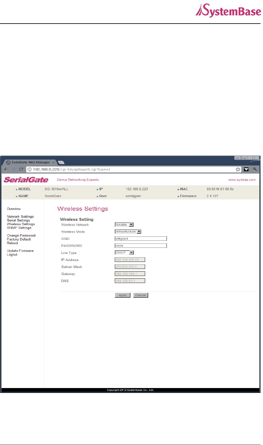
Wireless Settings
Only for SerialGate-1010w/ALL & SerialGate-1020w/ALL
A user can set the wireless network parameters.
After changing values, you need to click ‘Apply’ button. If you don’t want to change, you need to
click ‘Cancel’ button.
If you use the same network between LAN and WIFI, This environment is not working normally.
And so when you use the WiFi, you only use the LAN for configuration.

SerialGate User Guide
50
Menu Default Description
Wireless Network Disable
When enabled, WiFi is available.
•Disable: WiFi is not available.
•Enable: WiFi is available.
Wireless Mode Infrastructure
Set the wireless LAN mode.
(Option: Infrastructure, Ad-Hoc)
•Infrastructure : Use WiFi under the Infrastructure
mode. This mode is used for connecting to the wireless
AP (Access Point) as a client to connect to other
network.
•Ad-Hoc : Use WiFi under the Ad-hoc mode. This mode
is used for 1:1 communication with another Ad-hoc
client.
Wireless Network
Name
(SSID)
none
Sets the identification (SSID) of a wireless network to be
connected.
(Case sensitive & Up to 32 bytes using alphabets and
numbers) SSID should be same for all devices on the
same wireless network.
Channel Auto
Selects a frequency channel for wireless connection.
(Option: Auto, 1 ~ 13)
•Auto: Connect a channel specified in AP automatically.
In most cases, this setting is used.
•Value Specification: Specify a channel to be connected
manually.
Bitrate Auto
Sets the speed for wireless connection.
(Option: Auto, 1, 2, 5.5, 6, 9, 11, 12, 18, 24, 36, 48,
54Mbps)
Auto setting adjusts the speed depending on signal
sensitivity and noise. In most cases, this setting is used.
If Wireless Network mode is set to 802.11b/g Mixed, all
options can be selected.
802.11b only allows setting as 1, 2, 5.5 and 11Mbps.
802.11g only allows setting as 6, 9, 12, 18, 24, 36, 48
and 54Mbps.

SerialGate User Guide
51
If the setting is in low communication speed, it provides
more stable communication in an environment with a lot
of noise. Contrary to this, high communication speed
setting has higher risk of data loss in an environment
with a lot of noise.
Fragment
Threshold 2346
Sets the maximum packet size to send a packet after
dividing into small pieces. (Range: 256 ~ 2346 bytes)
Communication overhead is increased but
communication error can be reduced in serious
interference or noise environment.
In most cases, this setting is not used.
This feature will be disabled if 2346 is configured.
Authentication
Mode AUTO
(Option: AUTO, OPEN, SHARED, WPAPSK, WPA2PS
K)
An authentication mode defines the procedure that th
e 802.11 device uses when it associates with an acc
ess point.
•AUTO : Specifies IEEE 802.11 Auto System authenti
cation.
•OPEN : Specifies IEEE 802.11 Open System authen
tication.
•SHARED : Specifies IEEE 802.11 Shared Key authe
ntication that uses a preshared WEP key.
•WPA-PSK : Specifies WPA security. Authentication i
s performed between the supplicant and authenticator
over IEEE 802.1X. Encryption keys are dynamic an
d are derived through the preshared key used by the
supplicant and authenticator.
•WPA2-PSK : Specifies WPA2 security. Authenticatio
n is performed between the supplicant and authentic
ator over IEEE 802 1X. Encryption keys are dynamic
and are derived through the preshared key used by t
he supplicant and authenticator.
Encryption Type NONE
(Option: NONE, WEP, TKIP, AES)
Encryption modes define the set of cipher suites that can
be enabled on the 802.11 device.
•NONE : Encryption not used.

SerialGate User Guide
52
•WEP : Wired Equivalent Privacy (WEP) is the RC4-
based algorithm specified in the IEEE 802.11
specification.
•TKIP : Temporal Key Integrity Protocol (TKIP) is the
RC4-based cipher suite based on the algorithms defined
in the WPA and IEEE 802.11i specifications.
•AES : The Advanced Encryption Standard (AES)
defines an encryption algorithm in FIPS PUB 197.
Network Key none Type in Key value by Encryption Type.
Connection Type DHCP
Sets an IP address type in a wireless network.
(Option: DHCP, Static IP)
•DHCP : Assign a dynamic IP address through a DHCP
server.
•Static IP : Specify an IP address manually.
IP Address 192.168.1.72
Sets an IP address of a wireless network.
If the line Type is Static IP, a user can enter an IP
address directly. If line type is DHCP, the current IP
address is displayed. In DHCP type, the address cannot
be changed.
Subnet Mask 255.255.255.
0
Sets Subnet Mask of a wireless network.
If the line Type is Static IP, a user can enter a subnet
mask address directly. If line type is DHCP, the current
subnet mask address is displayed. In DHCP type, the
address cannot be changed.
Gateway 192.168.1.1
Sets a gateway address of a wireless network.
If the line Type is Static IP, a user can enter a gateway
address directly. If line type is DHCP, the current
gateway address is displayed. In DHCP type, the
address cannot be changed.
DNS 168.126.63.1
Sets a DNS server address of a wireless network.
If the line Type is Static IP, a user can enter a DNS
server address directly. If line type is DHCP, the current
DNS server address is displayed. In DHCP type, the
address cannot be changed.
SerialGate User Guide
53
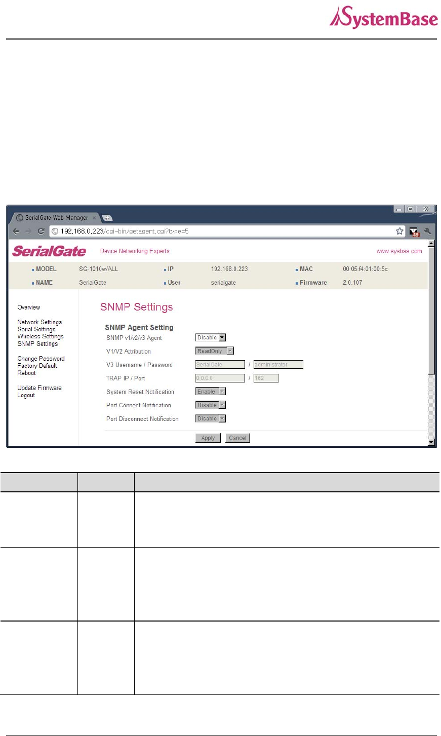
SNMP Settings
A user can set the communication and operation environment for the SNMP Agent.
After changing values, you need to click ‘Apply’ button. If you don’t want to change, you need to
click ‘Cancel’ button.
Menu Default Descriptions
SNMP
v1/v2/v3
Agent
Disable Enable or disable Simple Network Management Protocol (SNMP)
support. (Options : Disable/Enable)
V1/2
Attribution ReadOnly
SNMP V1/2 Attributes can read and write by SNMP Agent.
In order to read attributes only, change the feature to "ReadOnly".
In order to read and write attributes, change the feature to
"ReadWrite". (Options : ReadOnly/ ReadWrite)
V3 Attribution ReadOnly
SNMP V3 Attributes can read and write by SNMP Agent.
In order to read attributes only, change the feature to "ReadOnly".
In order to read and write attributes, change the feature to
"ReadWrite". (Options : ReadOnly/ ReadWrite)

SerialGate User Guide
54
V3 Username/
Password
serialgate
/administr
ator
Configure the Username and the password when use SNMP V3.
The Password is at least 8 character string
TRAP IP/ Port 0.0.0.0/16
2
Configure the server IP address and Port which receive the TRAP
information.
System reset
notification Enable If Enable is selected, notify the “System reset info.”
(Option : Enable, Disable)
Port connect
notification Disable If Enable is selected, notify the “Serial Port opened info.”
(Option : Enable, Disable)
Port
disconnect
notification
Disable If Enable is selected, notify the “Serial Port Closed info.”
(Option : Enable, Disable)
SerialGate User Guide
55
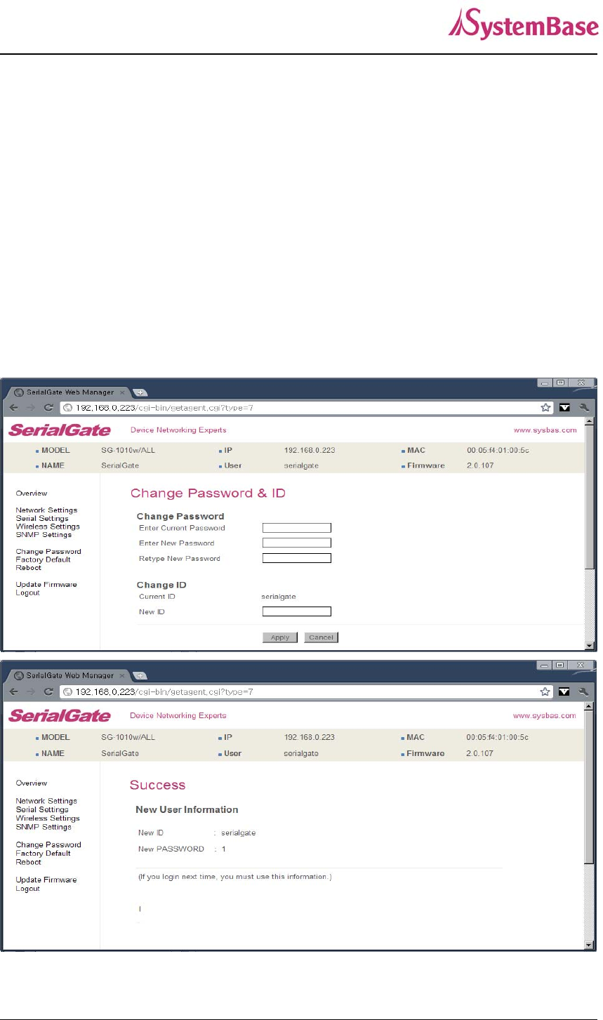
Change Password
Change username and password for an access to Web and Telnet.
After changing values, you need to click ‘Apply’ button. If you don’t want to change, you need to
click ‘Cancel’ button.
In case that a user forgot password, press Reset button for less than 3 seconds to restore the settings
back to factory default. However, please be aware that all other settings will be initialized and back to
factory default.
◆ Default user id : serialgate
◆ Default password : 99999999
SerialGate User Guide
56
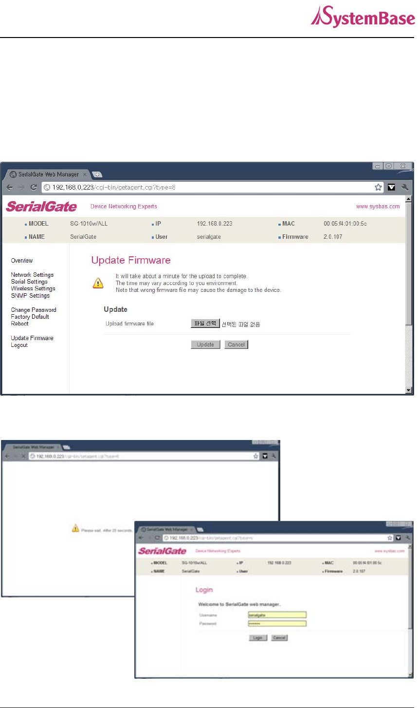
Update Firmware
Firmware is an application embedded in Flash memory of SerialGate. Set the location of the firmware
file to update, using the ‘Browse…‘ button. The selected firmware will be transferred to SerialGate
when you click ‘Start Update’.
After the transmission is complete, SerialGate will be automatically restarted to operate with the new
firmware. Then your browser is reloaded on the login page.
SerialGate User Guide
57
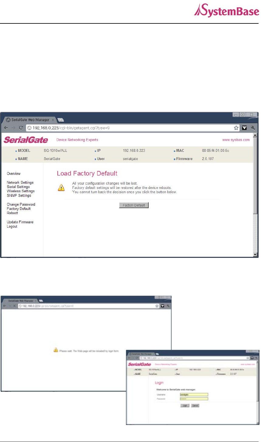
Factory Default
Restore all the configuration parameters to the factory default values. Clicking on ‘Restore Factory
Defaults’ button will delete all current settings and restore settings to the initial status, and SerialGate
will automatically reboot.
SG-1010, 1020, 1010(W)/ALL, 1020(W)/ALL : LAN Default IP Address 192.168.0.223, 10.10.1.1
SG-1040, 1080, 1160 : WAN Default IP Address 192.168.0.223, LAN Default IP Address 10.10.1.1
If Factory Default is complete, it shows the initialized IP address, username and password as below,
and restarts the device.
SerialGate User Guide
58
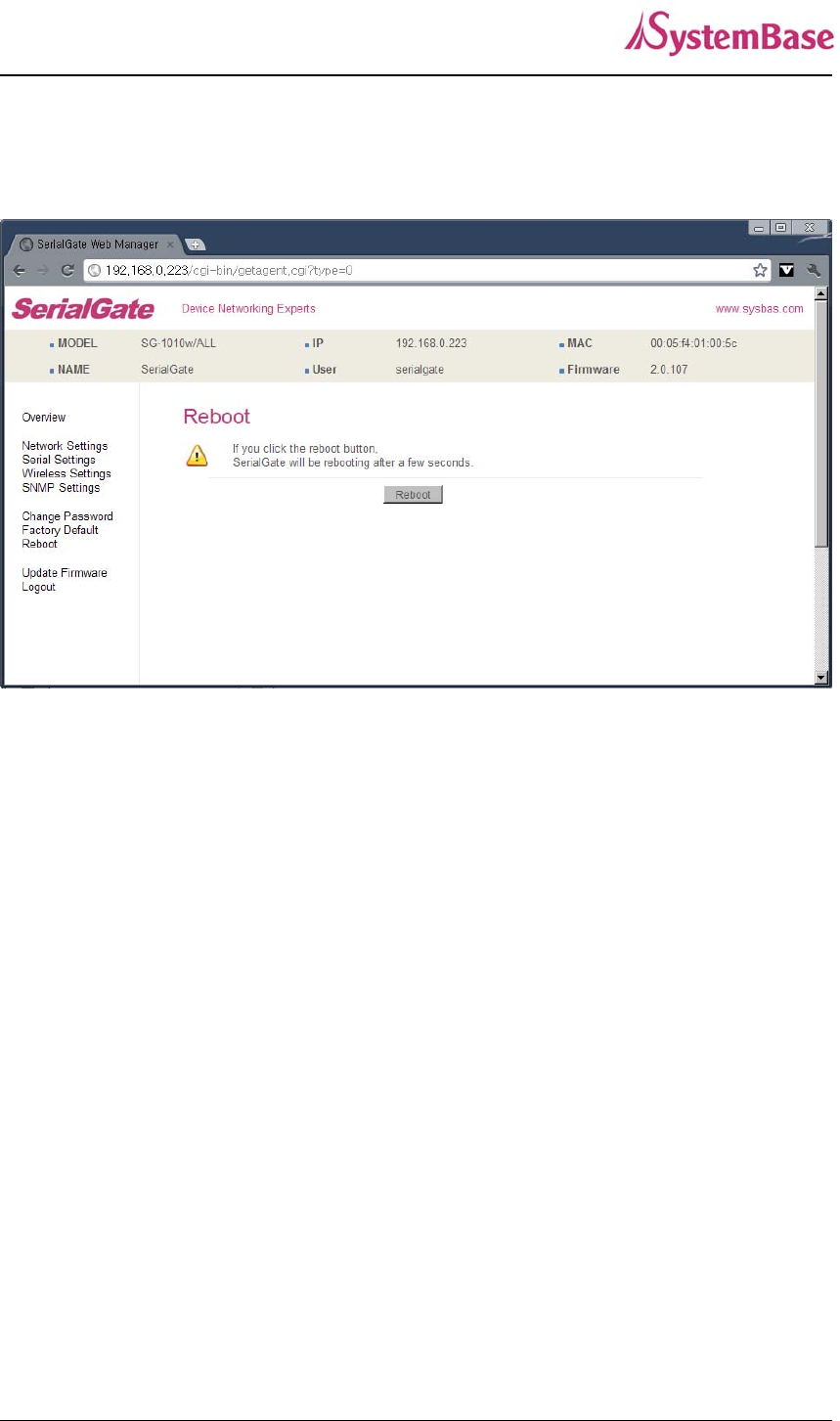
Reboot
This menu provides the reboot function via web.
After reboot, your browser is reloaded on the login page.
SerialGate User Guide
59
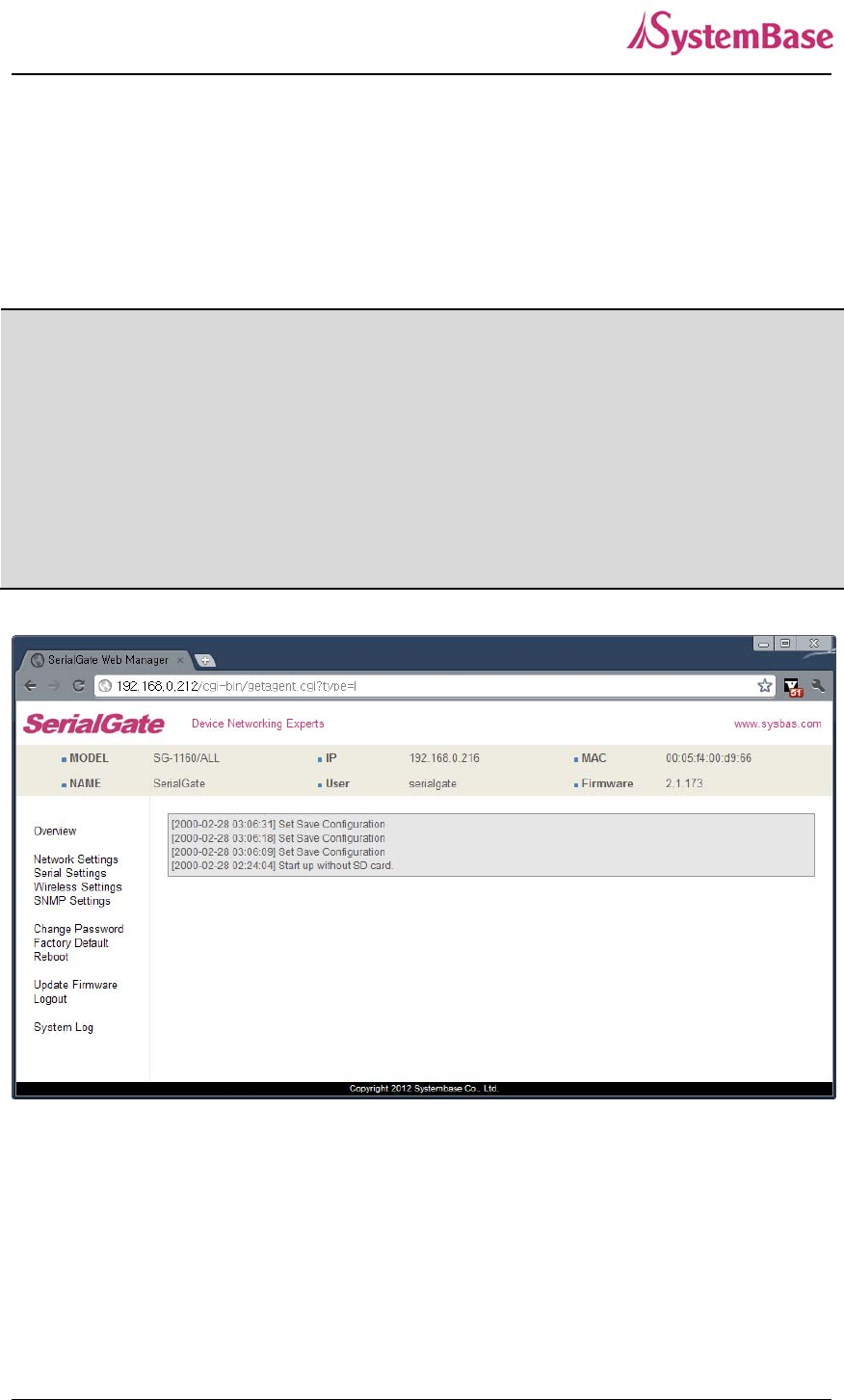
System Log
This feature confirms SerialGate’s system log information. (Only available for SerialGate-
1040/1080/1160) It records system startup and shutdown time, ending time of each port connection,
configuration and so on.
C:\>telnet 192.168.0.223
SerialGate Login : serialgate
Password :99999999
#test_rtc –-s 2010 7 8 15 00 00 Set Current time (
Y
ear, Month, Date,
Hour, minute, second)
#test_rtc –-g setting time
Get ioctl RTC Time = 2010-7-8, 15:00:05 Shows time elapsed
#reboot
SerialGate User Guide
60
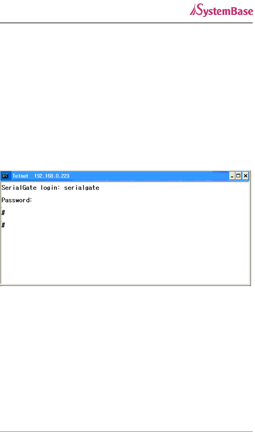
Ch. 6 Configuration via Telnet
Connection
Open your telnet client program and enter SerialGate’s IP address to connect. You need to enter
appropriate username and password to login. Please note that this username and password is used as
authentication method for Web as well. This means if username or/and password has been modified
from the telnet interface, modified values have to be entered to connect to web, and vice versa.
◆ Factory default username : serialgate
◆ Factory default password : 99999999
[def] commands - you can configure SerialGate’s settings.
[def help] commands - you can view current SerialGate’s settings.
After changing values, you can see modified values with ‘set view’ commands. But, be careful
because these values are not in effect unless you issue a ‘def save’ command. Changes will be
discarded if you do not save current settings.
SerialGate User Guide
61
View Commands
Commands related to View are as follows.
Command Description
def view Show all information about SerialGate
def view wan Show WAN network settings
def view management Show managing items settings
def view serial Show serial port settings
def help Show command list and help
Network Commands
Commands related to configuration of general network environment and network management are as
follows.
Command Default Description
def mac
<Mac Address> 00:05:f4:00:20:57 Register SerialGate’s MAC address
def line
[ip/dhcp] Static IP IP obtaining method for SerialGate’s network connection
def ip
<IP Address> 192.168.0.223
Display the current IP address
If line type is Static IP, manually enter an appropriate IP
address.
If line type is DHCP, it is not editable. Instead, current IP
address is shown.
def mask
<Subnet mask> 255.255.255.0
Display the current subnet mask address
If line type is Static IP, manually enter an appropriate
subnet mask address.
If line type is DHCP, it is not editable. Instead, current
subnet mask address is shown
def gateway
<Gateway
address>
192.168.0.1
Display the current Gateway address
If line type is Static IP, manually enter an appropriate
Gateway address.

SerialGate User Guide
62
If line type is DHCP, it is not editable. Instead, current
Gateway address is shown
def dns
<IP Address> 168.126.63.1 Set IP address of Domain Name Service
def portviewip
<IP address> 0.0.0.0
Configures IP of PC which Portview is installed
If IP is set to 0.0.0.0, Portview feature is disabled.
(Please refer to Portview User Manual in SerialGate
Utility & Documents CD for detailed information.)
def portviewport
<Port number> 4000 Set the socket number of a PC which Portview is installed.
def ftp
[enable/ disable] Enable Enable or disable FTP service.
If disabled, you cannot connect to SerialGate via FTP.
def telnet
[enable/ disable] Enable Enable or disable Telnet service.
If disabled, you cannot connect to SerialGate via Telnet.
def web
[enable/ disable] Enable Enable or disable Web service.
If disabled, you cannot connect to SerialGate via Web.
def ssh
[enable/ disable] Disable Enable or disable SSH service.
If enabled, you can connect to SerialGate via SSH.
def ddns
[IP Address] 203.32.117.1 If you set DDNS server IP, DDNS service will be enable.
But if you set “0.0.0.0”, this service will be disabled.
def ddnsuser
[username] serialgate Set username to access DDNS server.
def ddnspass
[password] 99999999 Set password to access DDNS server.
def name
[SerialGate
name]
Product Name Set the name of SerialGate. (Max 32 bytes)
def snmp
[enable/ disable] Disable
Enable or disable SNMP(Simple Network Management
Protocol)
- MIB-II(RFC 1213): System, Interface, IP, ICMP, TCP,
UDP - MIB-I (RFC 1317): Serial Interface
def v1readwrite
[enable, disable] Disable
SNMP V1/2 Attributes can read and write by SNMP Agent.
In order to read attributes only, change the feature to
"ReadOnly.”

SerialGate User Guide
63
In order to read and write attributes change the feature to
"ReadWrite.”
(Options : ReadOnly/ ReadWrite)
def v3readwrite
[enable, disable] Disable
SNMP V3 Attributes can read and write by SNMP Agent.
In order to read attributes only change the feature to
"ReadOnly.”
In order to read and write attributes change the feature to
"ReadWrite.”
(Options : ReadOnly/ ReadWrite)
def v3username
[string] serialgate Configure the Username to use SNMP V3.
def v3password
[string] none Configure the password to use SNMP V3.
def trapip
[address] 0.0.0.0 Configure the server IP address which transmits the TRAP
information.
def trapoprt
[Socket No.] 162 Configure the server Port which transmits the TRAP
information.
def trap_reset
[enable, disable] Enable If Enable is selected, inform the "System reset info".
def trap_connect
[enable, disable] Disable If Enable is selected, inform the "Serial Port opened info".
def
trap_disconnect
[enable, disable]
Disable If Enable is selected, inform the "Serial Port Closed info".
Serial Commands
You can set the communication and operation environment for serial port. Please refer to Chapter 5 for
details of each option.
Commands Default Description
def port x protocol
[disable,
com_redirect,
tcp_server,
Tcp_client,
com Select the operation protocol to be used in serial port.

SerialGate User Guide
64
Commands Default Description
tcp_broadcast,
Tcp_multiplex,
udp_server,
udp_client,
pair_master,
pair_slave,
modbus,
user]
def port x interface
[rs422,
ts485ne,
rs485e]
RS232,
RS422
Configure interface of serial port.
It is not available for RS232 model.
Combo model can choose from RS422, RS485-No-Echo
and RS485-Echo.
SerialGate-1160 can choose from RS232, RS422 and
RS485.
def port x socket
<port number> 4001
Set the socket number for the port. Com_redirect, TCP
Server, TCP Multiplex, TCP Broadcast, UDP Server,
Pair_Slave modes make use of this port for awaiting
network socket connections.
def port x name
<name> Port 1 Name each port for convenience. 16 Characters at
maximum
def port x speed
[150/300/600/1200/2
400/4800/9600/1920
0/38400/57600/1152
00/230400/460800/9
21600]
9600bps Set communication speed.
def port x data
[5 / 6 / 7 / 8] 8 Set the number of bits in each character size.
def port x stop
[1 / 2] 1 Set the number of stop bits.
def port x parity
[none/odd/even] none Set parity bit check scheme.
def port x flow
[none/xon/rts] none Set the flow control scheme.

SerialGate User Guide
65
Commands Default Description
def port x signal
[data/modem] data Set the signal line checking method for the device to be
connected to the given serial port.
def port x remote
<IP address> 0.0.0.0 Set IP address of the server to be connected in TCP Client,
UDP Client, Pair_Master mode.
def port 1
remoteport
<socket number>
4000
Set the socket number to connect to when the Operation
Mode is set to TCP Client or UDP Client or Pair_Master
mode.
def port x keepalive
<0 ~ 65535> 0
After a certain amount of time passes without any
communication after the socket connection between the
given serial port and the server is established, automatically
disconnect the socket connection.
def port x latency
<msec> 0 This needs to be set when consecutive data from the given
serial port needs to be transmitted to socket at once.
def port x txtrigger
[ auto, 1, 2, 4, 8, 16,
32, 64, 96, 128]
Set txtrigger of each port.
def port x rxtrigger
[ auto, 1, 2, 4, 8, 16,
32, 64, 96, 128]
Set rxtrigger of each port.
def port x fifosize
<1 ~ 128> Set fifosize of each port.
def port x login
<Enable/Disable> Disable When the Operation Mode is set to TCP Server, ask for the
username and password when the client tries to connect.
def port x loginname
<username> None When the Operation Mode is set to TCP Server, set the
username to ask for(Max 8 bytes)
def port x loginpass
<password> None When the Operation Mode is set as TCP Server, set the
password to ask for( Max 8 bytes)
def port x
termination
<Enable/Disable>
Disable Set termination for each port.
Username/Password Commands
Configure username and password for Web/Telnet/FTP.

SerialGate User Guide
66
Commands Default Descriptions
def username
<username> serialgate Set username to use in Web, Telnet, or FTP.
16 Characters at maximum.
def password
<password> 99999999 Set password to use in Web, Telnet, or FTP.
16 Characters at maximum.
System Commands
Commands Descriptions
def default Restore all settings to factory default. Requires reboot for changes to
take effect.
def apply Save and apply changed configuration settings.
Reboot Reboot Serialgate.
SerialGate User Guide
67
Ch. 7 Configuration via LCD
This feature is only for SerialGate-1160 model. A user of SerialGate-1010/1020/1040/1080 does not
need to read this chapter.
Through the LCD on the front panel, a user is able to test operation of each interface and configuration.
By default, the LCD displays communication status of each port, and by operating the keys next to the
LCD, the interface can be tested.
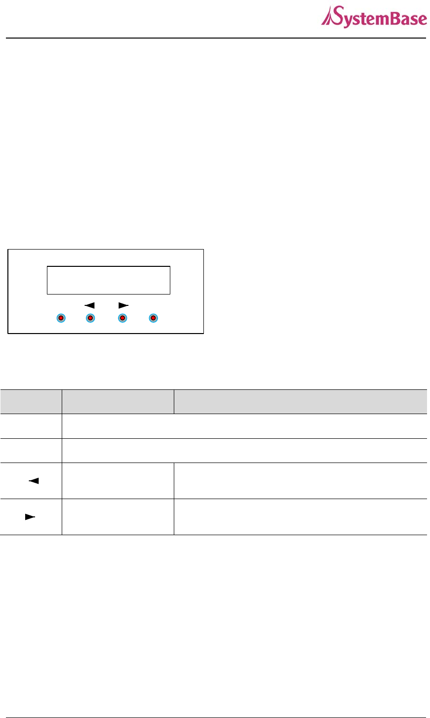
LCD and Key Operation
Port Status
---------------
ESC Enter
Graphic LCD is 16 Character * 2 Line, and four keys are to configure the operating environment.
The function of each key is as follows.
Key Function 1 Function 2
ESC Go to the top menu.
Enter Select the current value, and then go to the next menu
Previous menu/item If the variable is numeric, it increases the value
Ex.) 192.168.0.111 192.168.1.111
Next menu/item If the variable is numeric, move to the next space
Ex.) 192.168.0.111 192.168.0.111
Main Menu
Default screen of graphic LCD displays the status of each port.
Press ESC to go back to the main menu screen.
Main menu items are as follows.
Network Setup : Change the network configuration of device server.
Port Setup : Change the operating environment setting for each port.
SerialGate User Guide
68
Status : Check the connection status of the port and device server’s version information.
System : Perform firmware upgrade or reset, and initialization.
Verification : Verify each interface HW of device server.
Network Setup
Change the network configuration of device server.
In order to select Network Setup, press ‘ESC’ on the panel until ‘Main Menu’ comes up, and if ‘Main
Manu’ is displayed, press ‘<<’ or ‘>>’ until you see ‘Network Setup’. Then, press ‘Enter’ to change the
details.
At anytime ‘ESC’ is selected, it moves to the top menu and asks if a user wants to save the change in
Flash memory in case of a change made.
For more details about each menu, please refer to Chapter 5 “Configuration via Web” and Chapter 6
“Configuration via Telnet.”
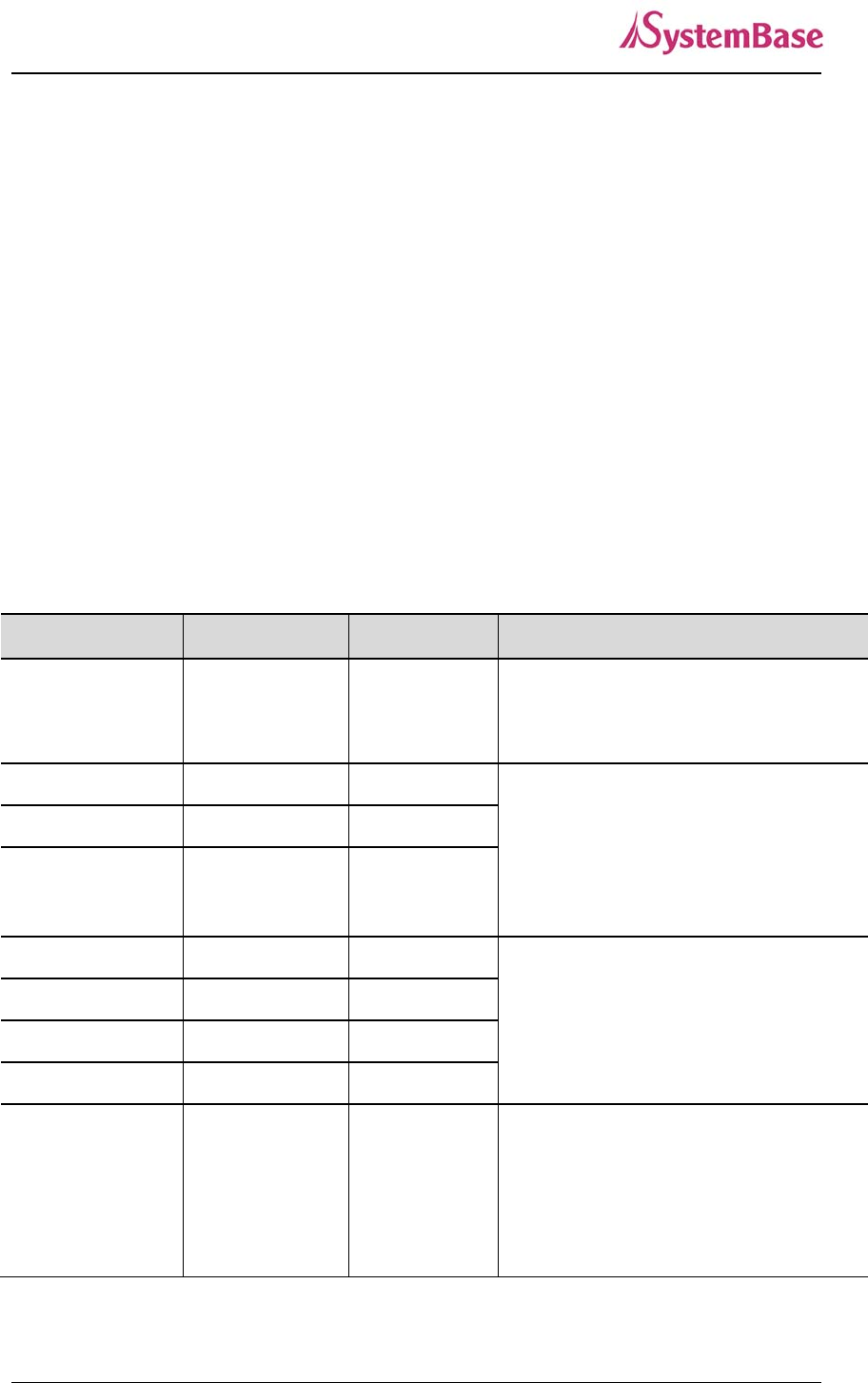
Menu and selectable options are as follows.
Menu Option Default Description
Network line Static IP, DCHP
Client Static IP
<<, >> : Select option
Enter : Save the current option, and go to
the next menu.
IP Address 192.168.0.223 <<: Increase the value of the cursor
position.
>>: Move cursor to the next space.
Enter : Save the current option, and go to
the next menu.
Subnet Mask 255.255.255.0
Gateway 192.168.0.254
FTP Service Enable, Disable Enable
<<, >> : Select option
Enter : Save the current option, and go to
the next menu.
Telnet Service Enable, Disable Enable
SSH Service Enable, Disable Disable
WEB Service Enable, Disable Enable
PortView Address 0.0.0.0
<<: Increase the value of the cursor
position.
>>: Move cursor to the next space.
Enter : Save the current option, and go to
the next menu.
SerialGate User Guide
69
Port Setup
Change the operating environment setting for each port.
In order to select Port Setup, press ‘ESC’ on the panel until ‘Main Menu’ comes up, and if ‘Main
Manu’ is displayed, press ‘<<’ or ‘>>’ until you see ‘Port Setup’. Then, press ‘Enter’ to change the
details.
At anytime ‘ESC’ is selected, it moves to the top menu and asks if a user wants to save the change in
Flash memory in case of a change made.
For more details about each menu, please refer to Chapter 5 “Configuration via Web” and Chapter 6
“Configuration via Telnet.”
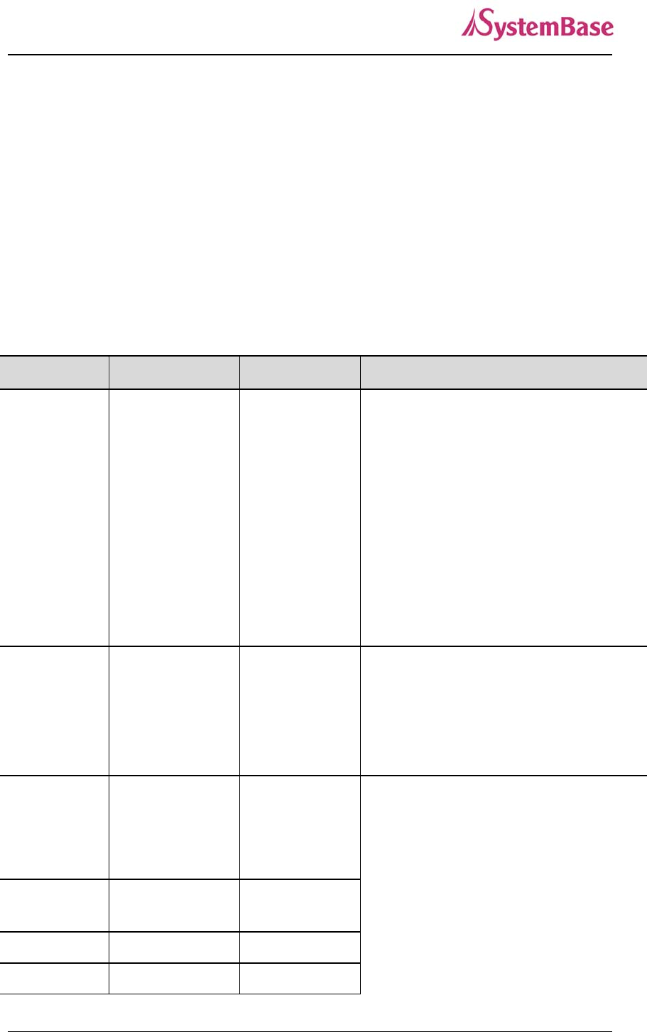
Menu and selectable options are as follows.
Menu Option Default Description
Protocol
Disable
Com_redirector
TCP_Server
TCP_Client
TCP_Broadcast
TCP_Multiplex
UDP_Server
UDP_Client
Pair_Master
Pair_Slave
Com_Redirector
<<, >> : Select option
Enter: Save the current option, and go to
the next menu.
Socket No. 4001 ~ 4016 4000 + Port
number
<<: Increase the value of the cursor
position.
>>: Move cursor to the next space.
Enter : Save the current option,
and go to the next menu.
Interface
RS232,
RS422
RS485 (NE)
RS485(E)
RS232
<<, >> : Select option
Enter: Save the current option, and go to
the next menu.
Device Type Data Only,
Modem Data Only
BaudRate 150 ~ 921600 bps 9600
Parity None, Odd, Even None
SerialGate User Guide
70
Data Bits 5 ~ 8 8
Stop Bits 1, 2 1
Latency_time 0 ~ 65535 0 <<: Increase the value of the cursor
position.
>>: Move cursor to the next space.
Enter: Save the current option, and go to
the next menu.
Keepalive 0 ~ 65535 0
Remote IP 0.0.0.0
Remote Port 4000
Termination Enable, Disable Disable
<<, >> : Select option
Enter: Save the current option, and go to
the next menu.
Status
Check the connection status of the port and device server’s version information
In order to select Status, press ‘ESC’ on the panel until ‘Main Menu’ comes up, and if ‘Main Manu’ is
displayed, press ‘<<’ or ‘>>’ until you see ‘Status’. Then, press ‘Enter’ to change the details.
At anytime ‘ESC’ is selected, it moves to the top menu.
Menu Display Description
Version L10b, K10a, F10a
B : Boot_loader Version
O : OS Version
F : Firmware Version
Port Status - - - - - - - - - - - - - - - -
If serial port is in communication, the port
number is displayed on the corresponding
space. Since it only shows one digit, it will
only display the second digit for 10~16
port.
System
Update device server firmware, initialize the system or command port reset.
In order to select System, press ‘ESC’ on the panel until ‘Main Menu’ comes up, and if ‘Main Manu’ is
displayed, press ‘<<’ or ‘>>’ until you see ‘System’. Then, press ‘Enter’ to change the details.
At anytime ‘ESC’ is selected, it moves to the top menu.
SerialGate User Guide
71
Menu Option Default Description
Port Reset
Cancel Yes Cancel
<<, >> : Select option.
Enter : If Cancel is selected, it moves to the
next menu. If Yes is selected, that action is
performed.
Factory Default
Reboot System
Firmware Update
Port Reset
If ‘yes’ is selected in Port Reset, LCD displays the port number from 1 to 16 as below, and the cursor is
at the first one.
P o r t R e s e t
1 2 3 4 5 6 7 8 9 0 1 2 3 4 5 6
Move the cursor to the port to be reset using ‘<<’, ‘>>’ keys and press ‘Enter’. Then, the corresponding
port will be reset.
Factory Default
Cancel and Yes are selectable with ‘<<’, ‘>>’ keys. If a user selects ‘Yes’ and ‘Enter’ in turn,
configuration resets to the factory default.
Reboot System
Cancel and Yes are selectable with ‘<<’, ‘>>’ keys. If a user selects ‘Yes’ and ‘Enter’ in turn, it prints out
‘Now Rebooting’ message and reboots the device server.
Firmware update
Update device server’s firmware. (OS, Filesystem)
In order to perform this feature, TFTP server and firmware image files should be prepared in PC.
Cancel and Yes are selectable with ‘<<’, ‘>>’ keys. If a user selects ‘Yes’ and ‘Enter’ in turn, it starts
device server firmware update.
First, register the name of firmware to be updated in PC. Firmware name by default is the filesystem
firmware name showing on the display.
SerialGate User Guide
72
F i r m w a r e N a m e
s g 1 1 6 1 – f s – 1 0 a . b i n
Using ‘>>’ key, move the cursor to the string that a user would like to modify and change the value with
‘<<’ key.
After registration of firmware name is complete, press ‘Enter’. Then, a user can input the IP address of
a PC that has TFTP server.
T F T P I P A d d r e s s
1 9 2 . 1 6 8 . 0 0 0 . 0 3 9
Default IP address is 192.168.0.39, and using ‘>>’ key, a user can move the cursor to the IP address
value to be changed. Using ‘<<’ key, a user can change the value.
After changing the IP address, if a user selects ‘Enter’, device server connects to the TFTP address,
downloads the firmware file, and starts updating. If the update fails, it prints out ‘Download Failed’
message. In this case, a user has to make sure if the registered firmware image’s name and TFTP
server’s IP address are correct. Also, check if TFTP server is running and there is a firmware in PC.
If the update is successfully complete, reset the device server power and operate it in a new firmware.
Verification
It verifies each interface HW of a device server.
In order to select System, press ‘ESC’ on the panel until ‘Main Menu’ comes up, and if ‘Main Manu’ is
displayed, press ‘<<’ or ‘>>’ until you see ‘Verification’. Then, press ‘Enter’ to change the details.
At anytime ‘ESC’ is selected, it moves to the top menu.
(*) When a user performs this test, all the program running in a device server stops. So, a user must
restart the device server after the test.
Menu Option Default Description
RS232(Loopback) Cancel Yes Cancel <<, >> : Select option.
SerialGate User Guide
73
RS232(Signal) Enter : If Cancel selected, go to the next menu.
If Yes selected, that action is performed.
RS422(Loopback)
RS485(Loopback)
Testing WAN Port
Testing LAN Port
Testing MMC
Testing Reset
Testing Console
Testing RTC
RS232 (Loopback)
Change all the serial ports of a device server to RS232, and conduct a Loopback test.
RS232 Loopback connector must be connected to all the serial ports for the test.
If a user selects ‘yes’ option, it starts Loopback test and prints out the result on LCD.
T e s t I n g ( R S 2 3 2 )
O O O O O O O O O O O O O O O O
If there is nothing wrong, it displays ‘O’ or ‘X’ otherwise.
RS232 (Seinal)
Change all the serial ports of a device server to RS232, and conduct a serial signal test.
RS232 Loopback connector must be connected to all the serial ports for the test.
If a user selects ‘yes’ option, it starts serial signal test and prints out the result on LCD.
T e s t I n g ( S I g n a l )
O O O O O O O O O O O O O O O O
If there is nothing wrong, it displays ‘O’ or ‘X’ otherwise.
RS422 (Loopback)
Change all the serial ports of a device server to RS422, and conduct a Loopback test.
RS422 Loopback connector must be connected to all the serial ports for the test.
SerialGate User Guide
74
If a user selects ‘yes’ option, it starts Loopback test and prints out the result on LCD.
T e s t I n g ( R S 4 2 2 )
O O O O O O O O O O O O O O O O
If there is nothing wrong, it displays ‘O’ or ‘X’ otherwise.
RS485 (Loopback)
Change all the serial ports of a device server to RS485, and conduct a Loopback test.
No additional loopback connector is required for RS485 since RS485 supports self Loopback.
If a user selects ‘yes’ option, it starts Loopback test and prints out the result on LCD.
T e s t I n g ( R S 4 8 5 )
O O O O O O O O O O O O O O O O
If there is nothing wrong, it displays ‘O’ or ‘X’ otherwise.
Testing WAN Port
Test WAN port of a device server.
For the test, WAN port must be connected to network, and there should be a PC with the IP address,
‘192.168.0.1’ for the Ping test on network.
If a user selects ‘yes’ option, it tries Ping to ‘192.168.0.1’, and prints out the result on LCD.
T e s t I n g W A N P o r t
OK !
If there is nothing wrong, it shows OK !’ or ‘Failed !’ otherwise.
Testing LAN Port
Test LAN port of a device server.
For the test, LAN port must be connected to network, and there should be a PC with the IP address,
‘192.168.0.1’ for the Ping test on network.
If a user selects ‘yes’ option, it tries Ping to ‘192.168.0.1’, and prints out the result on LCD.
T e s t I n g L A N P o r t
OK !

SerialGate User Guide
75
If there is nothing wrong, it shows OK !’ or ‘Failed !’ otherwise.
Testing MMC
It tests whether memory card of a device server can read and write.
For the test, SD card must be inserted to the device server.
If a user selects ‘yes’ option, it reads and writes the data on SD card, and prints out the result on LCD.
T e s t I n g M M C
OK !
If there is nothing wrong, it shows OK !’ or ‘Failed !’ otherwise.
Testing Reset
It tests whether ‘Reset’ button of a device server works.
If a user selects ‘yes’ option, it waits for ‘Reset’ key to be pressed for approximately 6 seconds.
If ‘Reset’ is pressed or 6 seconds passed, it shows the result on LCD.
T e s t I n g R e s e t
OK !
If there is nothing wrong, it shows OK !’ or ‘Failed !’ otherwise.
Testing Console
It tests whether console port of a device server works.
For the test, DB9 Loopback connector should be conned to all the console ports.
If a user selects ‘yes’ option, it starts Loopback test, and prints out the result on LCD.
T e s t I n g C o n s o l e
OK !
If there is nothing wrong, it shows OK !’ or ‘Failed !’ otherwise.
Testing RTC
It tests RTC interface working as a clock for the device.

SerialGate User Guide
76
If a user selects ‘yes’ option, it sets time up on RTC and prints out the result on LCD.
After the test, a user should reset the time and date.
T e s t I n g R T C
O K !
If there is nothing wrong, it shows OK !’ or ‘Failed !’ otherwise.
SerialGate User Guide
77
Ch. 8 Application
SerialGate can be used in many practical applications in various fields. Here we present some
of them.
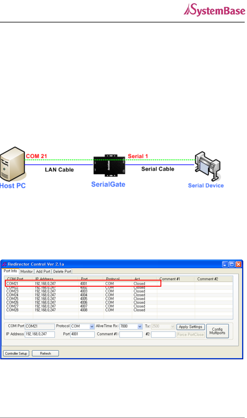
Com Port Redirector
With COM Port Redirection, a user can use serial port connected to SerialGate on the network
as if it is a serial port on PC.
Install Com Port Redirector and set the following steps. (For installation, please refer to Com Port
Redirector manual enclosed in CD.
In the picture below, IP address of SerialGate is 192.168.0.247, and the first serial port is being used. A
user can open Com 21 and use serial device connected to SerialGate.
SerialGate User Guide
78
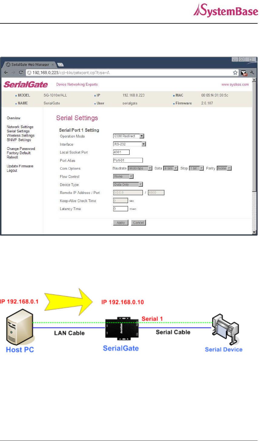
In order to correspond to the Redirector setting of PC, change the setting in the first serial port of
SerialGate as follows.
TCP_Server (TCP/IP connection from PC to SerialGate)
In PC’s socket program, connect the first serial port of SerialGate.
Since socket number for the first port of SerialGate is default 4001, try to connect to SerialGate’s IP
address and socket number 4001 when connecting from a PC to SerialGate.
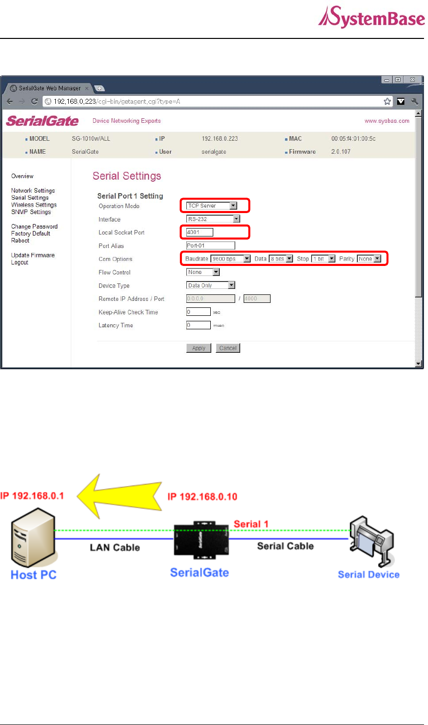
As shown below, change the Operation Mode to TCP_Server and confirm the socket number waiting
for connection. .
Check the communication speed of a serial device to be connected to serial port, and set it to Com
Specification.
SerialGate User Guide
79
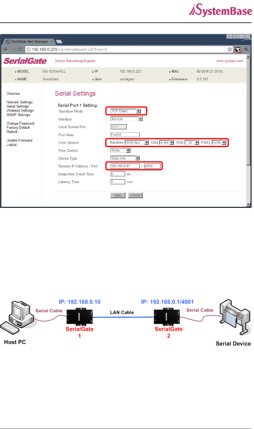
TCP_Client (TCP/IP Connection: SerialGate PC)
Since it is a connection from SerialGate to a PC, change the Operation Mode to TCP_Client and
register PC’s IP address and socket number to be connected.
Check the communication speed of a serial device to be connected to serial port, and set it to Com
Specification.
SerialGate User Guide
80
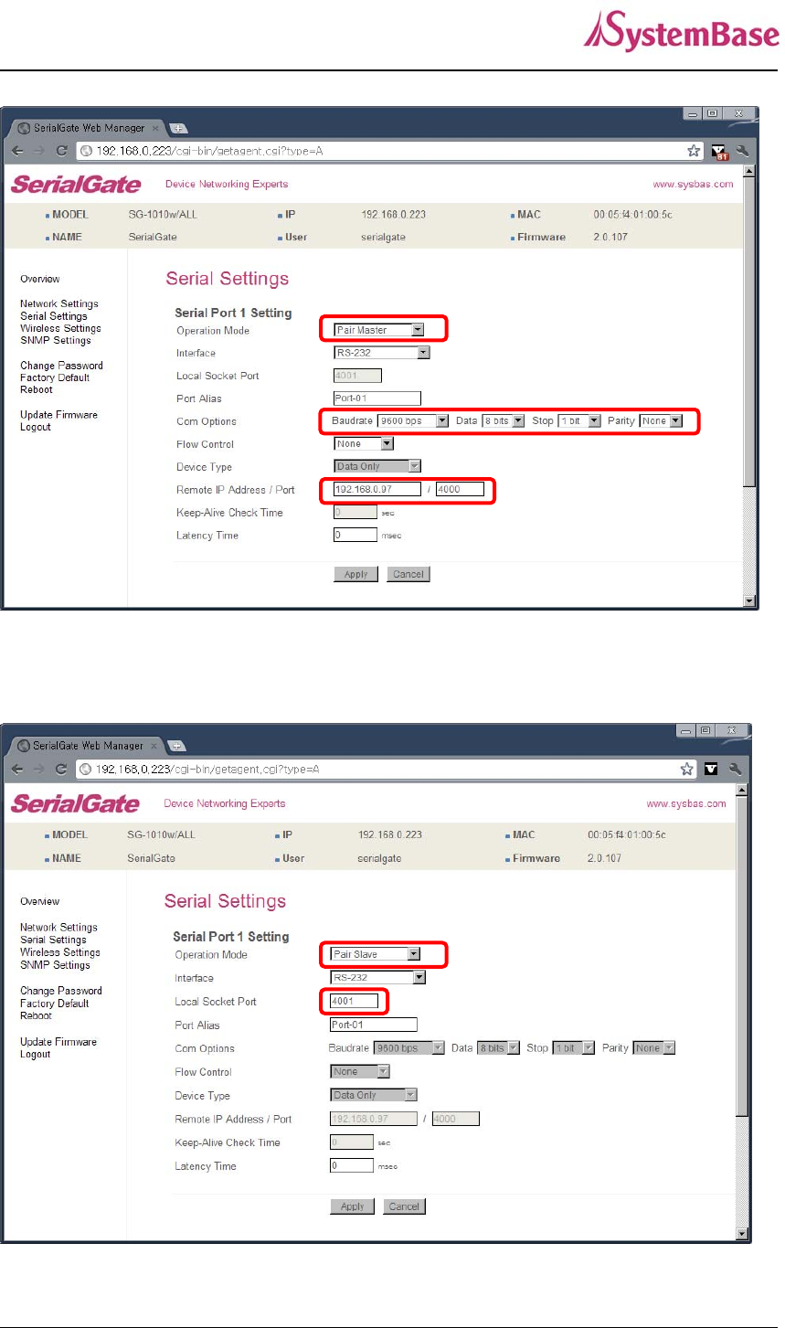
Pair (Serial Line To Serial Line)
This structure is mainly used when the cable length between PC and serial device is short so a user
needs to extend the communication distance. This approach consists of two SerialGates connected in
Pair.
Setting for SerialGate 1
In order to perform Master features, change Operation Mode to Pari_Master. Check the
communication speed of a PC and set it in Com Specification, and also register Slave SerialGate’s IP
address and port number in Remort IP/Port.
SerialGate User Guide
81
Setting for SerialGate 2 In order to wait for Master connection, set Operation Mode to Pari_Slave and
register the socket number to be connected in Local Socket Port.

SerialGate User Guide
82
Ch. 9 Appendix
Troubleshooting
This section describes procedures for troubleshooting problems you may encounter with
SerialGate.
Troubleshooting Installation Problems
If you cannot access the connected serial device via SerialGate, first check the network
connection and cabling.
Check the physical cabling to ensure all cables are plugged in (Ethernet and DB-9 se
rial cable)
If the appropriate LEDs are not illuminated, then there is probably a bad 10baseT or
100baseTX cable, or the hub port is bad. If possible, try a different cable and hub p
ort, or try connecting a different device to the cable.
Verify that you are using the correct values for both IP Address and Port Number.
If you are using a hub, verify that the hub port is operating correctly by trying Serial
Gate on a different port.
Troubleshooting Network Configuration Problems
If you are using TCP/IP, make sure that your computer and SerialGate are on the sa
me IP segment or can reach each other with a PING command from the host. The I
P address you assign to SerialGate must be on the same logical network as your ho
st computers (e.g., if your computer has an IP address of 192.189.207.3 and the sub
net mask of 255.255.255.0, SerialGate should have an IP address of 192.189.207.x,
where x is an integer between 1 and 254), or you must properly configure your route
r address to work with SerialGate.
If your Device Server is set to Auto or DHCP for obtaining an IP Address, it is possi
ble that SerialGate’s IP address can change. Either configure your DHCP server to
give SerialGate a permanent lease, or configure SerialGate to be on a STATIC IP ad
dress outside the scope of the DHCP addresses.

SerialGate User Guide
83
The problem may be the result of mismatched or duplicate IP addresses. Verify that
the IP address is correctly loaded into SerialGate (via the displayed or printed configu
ration information or through the remote console), and make sure that no other nodes
on the network have this address (duplicate addresses are the biggest cause of TCP/
IP connectivity problems). If the IP address is not correct, then check whether the lo
ading procedure was properly executed.
Also verify that the host computer and SerialGate are using the same subnet masks(f
or example, if SerialGate has a subnet mask of 255.255.255.0, the host must have th
e same subnet mask) or that the router is properly configured to pass data between
the two devices.
If the wrong IP address is loaded, check your network for DHCP server, and make s
ure that the server is not set up to load wrong IP addresses into SerialGate.
Troubleshooting Windows Problems
If you are having trouble accessing the connected serial device through Windows, ens
ure you can ping SerialGate using the command PING x.x.x.x, where x.x.x.x is the IP
address of SerialGate. If you cannot ping SerialGate, you will not be able to access
the serial device.
If you are running COM port redirector and the software reports an error, verify that t
he correct virtual COM port is being used when the application runs. Verify that your
application’s COM port settings have been changed to use the virtual COM ports.
Firmware Update using FTP
A user can upload firmware using web browser, FTP, and etc.
1) Connect to SerialGate with FTP, using correct username and password. (Default: serialgate,
99999999)
2) Issue a command ‘bi’ for binary file transfer mode. Optionally use ‘hash’ to see the data
transfer mark.
3) Issue ‘put’ command to upload the firmware file.
4) After getting a ‘Transfer complete’ message, issue a command ‘bye’ to disconnect. Now we
are ready to update the firmware.
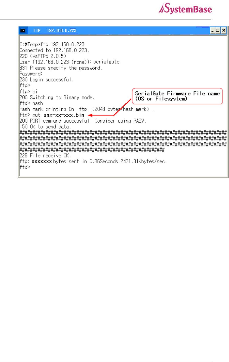
SerialGate User Guide
84
5) Connect to SerialGate via Telnet, using correct username and password. (Default: eddy,
99999999)
6) After the login, you are already at the default directory where the firmware resides. Update
can start right away.
7) Issue a command ‘ls’ to make sure firmware files are both successfully uploaded.
8) Use ‘upgrade’ command to write this file into SerialGate’s Flash memory. Upgrade application
automatically detects whether the given firmware is kernel or file system.
9) Usage: Upgrade <firmware name> (Filename is case-sensitive.)
10) Make sure ‘Flash Write OK’ and ‘Flash Verify OK’ messages are displayed.
11) Enter ‘reboot’ to restart SerialGate. Now SerialGate will run with the new firmware.
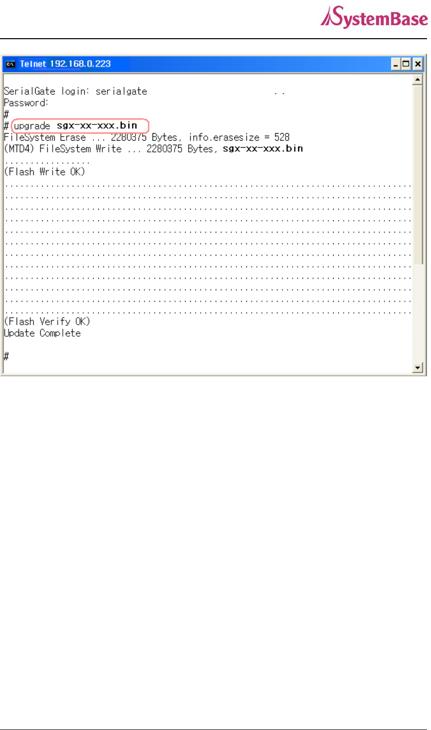
SerialGate User Guide
85
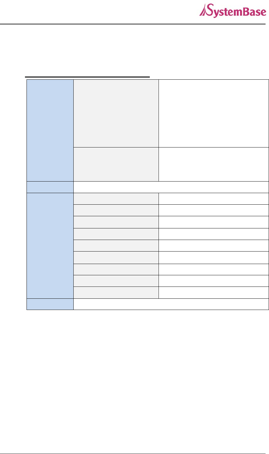
SerialGate User Guide
86
Product Specification
Communication
LAN Port
SerialGate-1010
SerialGate-1010/ALL
SerialGate-1010w/ALL
SerialGate-1020
SerialGate-1020/ALL
SerialGate-1020w/ALL
10/100Mbps RJ-45 Port * 1EA
SerialGate-1040
SerialGate-1080
SerialGate-1160
10/100Mbps RJ-45 Port * 2EA
Network Static IP, DHCP IP
Number of Serial
Ports
SerialGate-1010 1 Port ( RS232 or COMBO(RS422/RS485) )
SerialGate-1010/ALL 1 Port ( RS232/RS422/RS485 )
SerialGate-1010w/ALL 1 Port ( RS232/RS422/RS485 )
SerialGate-1020 2 Ports ( RS232 or COMBO(RS422/RS485) )
SerialGate-1020/ALL 2 Ports ( RS232/RS422/RS485 )
SerialGate-1020w/ALL 2 Ports( RS232/RS422/RS485 )
SerialGate-1040 4 Ports ( RS232 or COMBO(RS422/RS485) )
SerialGate-1080 8 Ports ( RS232 or COMBO(RS422/RS485) )
SerialGate-1160 16 Ports ( RS232/RS422/RS485 )
Serial Max Speed Max 921.6kbps
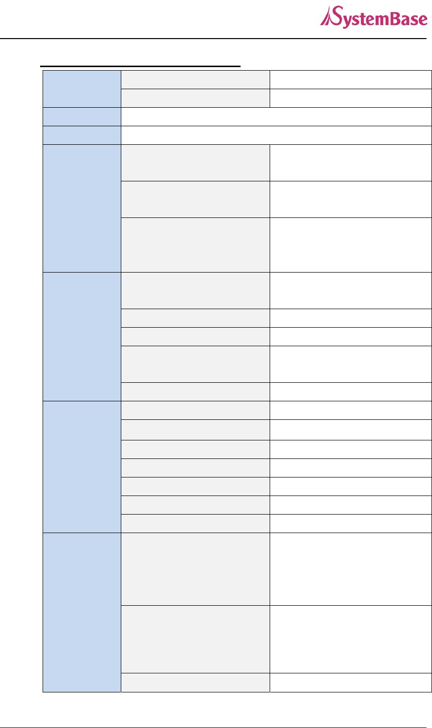
SerialGate User Guide
87
Hardware
Process
SerialGate-Series 400Mhz
SerialGate-1010,SerialGate-1020 only 210Mhz
Flash Memory 8MByte (SerialGate-1010: 4MByte)
SDRAM 32MByte
Power
SerialGate-1010
SerialGate-1020
DC 9 ~ 30V Adapter(Terminal Block)
SerialGate-1010(W)/ALL
SerialGate-1020(W)/ALL
DC 12V Adapter(Terminal Block)
SerialGate-1040
SerialGate-1080
SerialGate-1160
AC : 100 ~ 245 VAC(Free Volt)
DC : DC 12V Adapter(Terminal Block)
Size
SerialGate-1010
SerialGate-1020
71.9(W)*107.5(L)*25.2(H)mm
SerialGate-1010(W)/ALL 65(W)*79.5(L)*24.3(H)mm
SerialGate-1020(W)/ALL 80.9(W)*110.5(L)*24.3(H)mm
SerialGate-1040
SerialGate-1080
240(W) * 150(L)* 50(H)mm
SerialGate-1160 430(W) * 193(L)* 45(H)mm
Weight
SerialGate-1010 125 g
SerialGate-1020 135 g
SerialGate-1010(W)/ALL 180 g (Antenna included, Antenna: 15g)
SerialGate-1020(W)/ALL 256 g (Antenna included Antenna: 15g)
SerialGate-1040 1,180 g
SerialGate-1080 1,215 g
SerialGate-1160 2,480 g
Operation
Temperature
SerialGate-1010
SerialGate-1020
SerialGate-1010/ALL
SerialGate-1020/ALL
-40℃ ~ 85℃
SerialGate-1010W/ALL
SerialGate-1020W/ALL
-10℃ ~ 70℃
SerialGate-1040 0℃ ~ 50℃

SerialGate User Guide
88
SerialGate-1080
SerialGate-1160
Serial Port Signal
SerialGate-1010 TX, RX, DTR, DSR, CTS, RTS, DCD
SerialGate-1020
Port 1: TX, RX, DTR, DSR, RTS, CTS, DCD
Port 2: TX, RX, RTS, CTS
SerialGate-1010(W)/ALL TX, RX, DTR, DSR, CTS, RTS, DCD
SerialGate-1020(W)/ALL
Port 1: TX, RX, DTR, DSR, RTS, CTS, DCD
Port 2: TX, RX, RTS, CTS
SerialGate-1040
SerialGate-1080
SerialGate-1160
TX, RX, DTR, DSR, CTS, RTS, DCD
Humidity Max 95% R.H
LED Power ,Serial ,Ready, Link
Serial Port
Protection
± 15kV ESD Protection
SD/MMC CARD
SerialGate-1040
SerialGate-1080
SerialGate-1160
SD Support(Max 32GB)
Reset Button
Feature Action Result
Warm Booting Press for less than 3 sec. SerialGate reboots
Factory Default Press for more than 3 sec. Restores the default setting
Software
Protocol TCP, UDP, Telnet, ICMP, DHCP, TFTP, HTTP, SNMP 1/2/3, SSH, SSL
Management Tool Portview
Configuration Telnet, Web
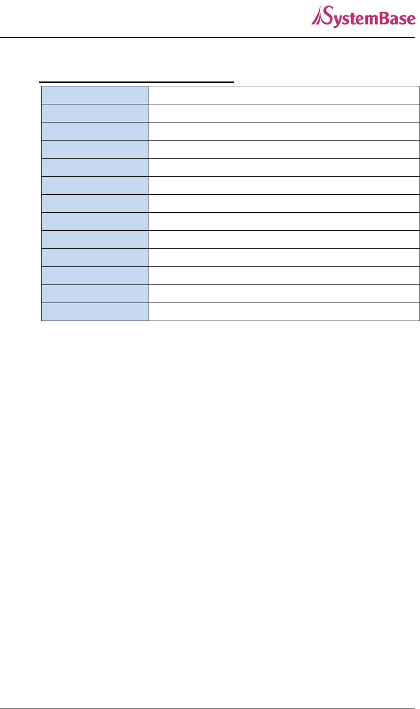
SerialGate User Guide
89
Ordering Information
SerialGate-1010 (RS232) 1 x Serial Port (RS232 only)
SerialGate-1010 (Combo) 1 x Serial Port (RS422/RS485 selectable)
SerialGate-1010/ALL 1 x Serial Port (RS232/RS422/RS485 selectable)
SerialGate-1010w/ALL 1 x Serial Port (RS232/RS422/RS485 selectable)
SerialGate-1020 (RS232) 2 x Serial Port (RS232 only)
SerialGate-1020 (Combo) 2 x Serial Port (RS422/RS485 selectable)
SerialGate-1020/ALL 2 x Serial Port (RS232/RS422/RS485 selectable)
SerialGate-1020w/ALL 2 x Serial Port (RS232/RS422/RS485 selectable)
SerialGate-1040 (RS232) 4 x Serial Port (RS232 only)
SerialGate-1040 (Combo) 4 x Serial Port (RS422/RS485 selectable)
SerialGate-1080 (RS232) 8 x Serial Port (RS232 only)
SerialGate-1080 (Combo) 8 x Serial Port (RS422/RS485 selectable)
SerialGate-1160 (All) 16 x Serial Port (RS232/RS422/RS485 selectable)