Contents
- 1. Manual 1
- 2. Manual 2
Manual 1

Instruction manual
BPX and TWIN Station
interface boxes
English

2

3
CONTENTS
1 Introduction 4
2 Safety precautions 4
3 Overall description 4
4 Measuring (Examples) 5
5 Sales programme 6
6 Data processing system 7
6.1 TIS software 7
6.2 User’s interface 7
6.3 Command library 7
7 BPX Station 8
7.1 Technical data 8
7.2 Elements at the front panel 8
7.3 Elements at the rear panel 9
7.4 IN/OUT connector 9
7.5 Operating mode 10
7.5.1 Normal mode 10
7.5.2 Stand-alone mode 11
8 TWIN Station 13
8.1 Technical data 13
8.2 Elements at the front panel 13
8.3 Elements at the rear panel 14
9 LEDs 14
9.1 LED status on both BPX and TWIN Station 14
9.2 LED status on the BPX in stand-alone mode 15
9.3 LED status related to an error message 15
10 Assembly and connection 16
10.1 Assembly 16
10.2 Connection 17
11 Recycling 18
11 Guarantee 18
12
Declaration of conformity with confirmation of traceability of all indicated values
18

4
1 INTRODUCTION
First of all, we thank you for the purchase of
an interface box intended for use with TESA’s
probes. In order to help you obtaining the best
from its operational possibilities, we advise to
read this manual carefully beforehand.
3 OVERALL DESCRIPTION
2 SAFETY PRECAUTIONS
Both BPX box and TWIN Station are key com-
ponents of our product line dedicated to multi-
gauging measurement.
Each unit permits inductive probes made by
TESA to be connected to any system featuring a
USB interface and used for data processing.
Their modern design, which is based on the lat-
est technologies, allows for a flexible, fast and
independent run of the measuring functions.
Their robust construction provides the security
as required in the most demanding surround-
ings and production areas.
The choice of the system for data processing is
left to the user. Once connected to a host com-
puter fitted with a USB port, each unit will be
capable to run the following:
– TIS software provided with the BPX box /
TWIN Station and used for setting, defining
the measurement functions and measuring.
– Restricted interface for all settings and com-
mands.
– Command library allowing for a direct dia-
logue.
– Use only the power supply and the charger
supplied with the BPX box or TWIN Station.
– Do not attempt to dismantle the box, except
for those parts listed in this manual. Other-
wise you may damage the unit or cause a
failure.
– Do not expose the probes to excessive force
or to shocks. These sensitive instruments
must be handled with care (refer to the
probe’s instruction manual).
– Do not drop or expose your interface box to
shocks. Although robust, the built-in measur-
ing system may be damaged, thus leading to
incorrect measured values.
The software is designed to meet the various
needs in multigauging measurement, while of-
fering optimum flexibility in terms of inspection
means. Each measuring function can easily be
defined.
All trained users will appreciate the possibility to
partly merge the TIS software, even to directly
communicate with each box running their own
software.
These interface boxes of the latest generation
stay ahead due to their key features, i.e.:
– Robust – Resistant aluminium housing, also
flexible for assembly by means of the conven-
ient accessory.
– Reliable – Use of start-of-the-art compo-
nents combined with a Swiss manufacturing
for high quality standard.
– Modular – Full compatibility with various
technologies, thus offering a solution that
meets the user’s needs.
– Universal – Unlimited use of each interface
box.
Moreover, a strict adherence to the safety
precautions is the guarantee for reliable
measurement results over a long period of use.
5
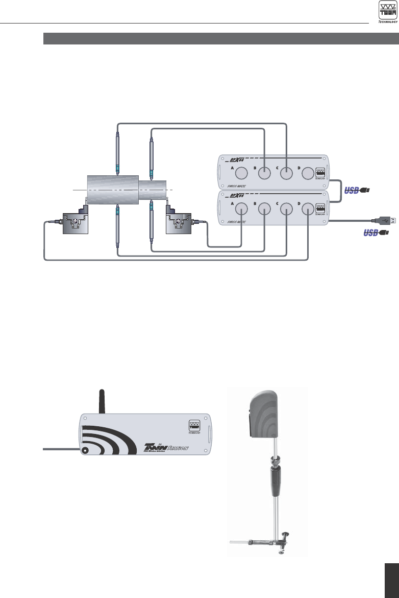
4 MEASURING (EXAMPLES)
Typical multigauging measurements
The synchronization of up to 64 probes linked
together using a number of stackable BPX
interface boxes allows synchronized static or
Dynamic measurement through a wireless
connection
When the probe cable is restricting the move-
ment of the operator, or generates a measure-
ment error due to its displacement, precision
and freedom are significant advantages of a
wireless connection.
dynamic measurement. Input/Ouput signals can
be used for measurement command and result
classification.
Each TWIN Station is able to connect up to
8 wireless probes. When used simultaneously
with probes from additional BPX boxes or TWIN
Station, these probes are synchronized.
2.0
2.0
SWISS
MADE
32.30019
PAT PEND
SWISS
MADE
32.30019
PAT PEND
2.0 2.0
2.0
SWISS
MADE
32.30019
SWISS
MADE
32.30019
6
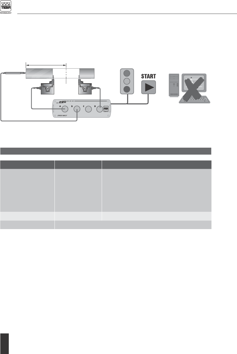
5 SALES PROGRAMME
Measurement in stand-alone mode
The BPX box is capable to operate indepen-
dently in extreme surrounding conditions, or
if the measurement results in a simple value
classification.
Once properly configured, the BPX box can
be disconnected from the PC and used alone
through the signal inputs/outputs only.
SWISS
MADE
32.30019
PAT PEND
SWISS
MADE
32.30019
PAT PEND
*Delivery scope
– Interface box
– Instruction manual
– CD-ROM (drivers and TIS software)
– USB cable, 1,80 m long (used to connect the BPX boxes to each other
or for connection to the PC.
Order No. Description Signal inputs/outputs
05030010*
Including:
04761054
04761055
04761056
BPX 44
Power supply
EU and CH cable
US cable
4 TESA half-bridge probes
4 TESA half-bride probes, linearized
100 to 240 V∼, 50-60 Hz
05030012* TWIN Station 8 TESA wireless probes
05060009 Mounting brackets (4 items)

7
6 DATA PROCESSING SYSTEM
A single or several BPX or TWIN Station inter-
face boxes can be connected to a host computer
fitted with a USB interface.
6.1 TIS software
This software allows for a correct setting of
each peripheral device as well as both interface
boxes and probes. Running it will also enable
you to conveniently define the measuring func-
tions, capture the measured value and export
the results.
In addition, the BPX box lets the operator con-
figure the stand-alone mode (no PC) and moni-
tor the signal inputs and outputs.
Minimum profile requirements for used PC:
– Windows XP sp3
– .NET Framework 3.5
– Hard disk, 1GB
– Image resolution to 900 x 600 pixels
For further information about the TIS software,
please refer to the instruction manual available
on the CD-ROM delivered.
The port used for data transmission is a virtual
COM port.
6.2 User’s interface
The User’s interface makes it possible for the
main tabs provided with the TIS Software to be
downloaded in another programme. Running
TIS partly allows for easy control of the settings
made for both BPX and TWIN Station, including
the assignment of the measuring channels and
functions, without the need for the measure-
ment to be taken.
This software tool is intended for systems used
for data processing or data acquisition, which
do not provide the core structure needed to han-
dle complex measuring functions.
Additional information is available upon re-
quest.
6.3 Command library
The command library enables a direct com-
munication with the BPX or TWIN Station. This
solution is convenient for those programmers/
integrators who want to use a proprietary inter-
face.
Additional information is available upon re-
quest.
8
Measuring range, commutable
(common to two channels)
±2000 µm/±200 µm
±5000 µm/±500 µm (long travel probes)
(Indication error range of the digital output
(at 20±1°C and ≤ 50% HR
≤ ± (0.05 µm + 0.15%) of the measure
range
Zero point drift
(at 20±1°C and ≤ 50% HR)
≤ ± 0.05 % / °C
Sensibility drift
(at 20±1°C and ≤ 50% HR)
≤ ± 0.05 % / °C
Acquisition time
– between 2 subsequent measurements
– for the synchronisation
≤10 ms
≤1 ms
Data transfer duration
– from the serial digital output (USB)
Depends on the operating system
of the PC
PC ports
– USB hub
USB 2.0
3 external ports (≤100 mA)
Input voltage of the power supply 115 to 230 Vrms – 50-60 Hz, -10% to 15%
Output voltage of the power supply 7 V typ. at nominal load
Rated operating temperature 20°C ±1°C
Operating temperature range 10 to 40°C
Storage temperature range -10 to 60°C
Overall dimensions 55 x 172 x 155 mm (H x L x P)
BPX box weight 1 kg
Degree of protection IP40 according to IEC/CEI 529, DIN 40050
Robust aluminium housing
Electromagnetic compatibility To IEC/EN 61326-1, US to CFR 47, part 15,
subpart B, Class B digital device
Assembly Using the mounting brackets (accessory)
and the screws of the front / rear panel
Probe voltage and drive frequency 2.8 Vrms typ. – 13 kHz ±0,5%
Signal output for value classification 3 relay digital outputs (max. 50 V, 500 mA)
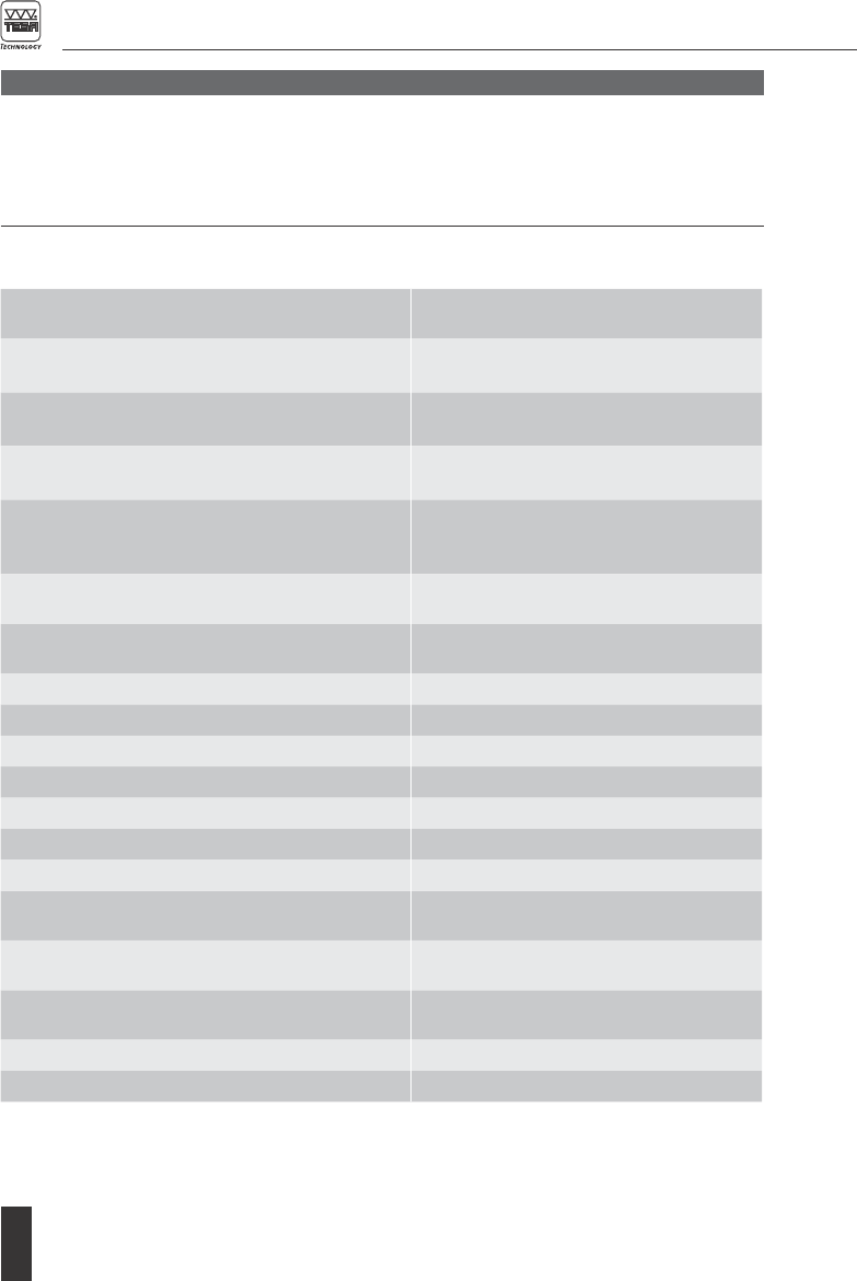
7.1 Technical Data
7 BPX STATION
BPX is a universal electronic interface used for
connecting half-bridge probes made by TESA.
This box incorporates a multiplexer permitting a
series connection of several boxes as well as a
monitoring of input and output signals.

9
7.2 Elements at the front panel
1
7.3 Elements at the rear panel
Rear panel of the BPX box
1 Mains connector for
the power supply
(required to operate
the box).
2 USB type B connec-
tor, (to the PC or to
other BPX box).
3 USB type A connec-
tor, (for additional
BPX boxes or TWIN
Station).
4 IN/OUT connector.
5 LEDs (box ID number
or error message).
1 Signal input connec-
tor for standard TESA
half-bridge probes
(A, B, C and D)
1 2 3 4 5
7.4 IN/OUT connector
The 15-pin female connector, type D-sub, serves
for transmitting any emitted analogue signal
from the input channel, but also for monitoring
all digital input and output (IN/OUT) signals.
Front panel of the BPX box
BPX Sub-D 15p female
connector
8
9
15
1

10
Pin
Signal Functions
4 OUT1
Yellow for rework
5 OUT3 Red for scrap
6 +U
Output, about 7 V, 50 mA max.
7 IN com Red for scrap
8 GND Mass, 0 V
9 DRXD
–
Pin
Signal Functions
10 DTXD
–
11 OUT com Shared output
12 GND
Mass, 0 V
13 OUT2
Green for good
14 IN1
Input
7.5.1 Standard mode
This mode requires a PC with the TIS software
installed. The software manages the BPX and
TWIN Station connected.
To connect the BPX, proceed as described
hereunder.
Procedure Description
Connect the power
supply
LEDs 1, 2 , 4 and 8 blink.
Connect the USB cable The PC detects the USB-Hub on the BPX.
If the BPX has never been connected to the PC previously, this BPX
box will be identified as a new peripheral device, thus requiring for the
installation of the driver TESA BPX/BPW. Once this driver is installed
and the BPX detected, the LED’s stop blinking and indicate the ID box
number.
Note
If the power supply
is removed
One or several LEDs will blink. In this case, the BPX box is able to
communicate, but unable to measure.
Connect the power supply first, then the USB cable
7.5 Operating mode
BPX box can operate in two different modes,
depending on its state when disconnected from
the PC and power supply.
There are two operating modes:
1 Standard mode
2 Stand-alone mode

11
Procedure Description
Connect USB cable All LEDs blink.
The PC detects the USB-Hub on the BPX.
Connect power supply If the BPX has never been connected to the PC previously, this BPX
box will be identified as a new peripheral device, thus requiring the
installation of the driver TESA BPX/BPW. The LEDs 1, 2, 4 and 8 then
display ID box number.
Note - If the power
supply is removed
One or several LEDs blink. In this case, the BPX box is able to com-
municate, but unable to measure.
Connect the USB cable first, then the power supply
This mode is intended to operate the BPX Box
independently from the PC. All setting opera-
tions - i.e. setting the master value, collecting
the measured value and displaying the result
classification - are done through the pins on the
15-pin D-Sub connector.
Since a series connection is not allowed in
this mode, only one BPX box can be used. The
highest number of probes accepted for the
measurement is 4.
Once the parameters defined and the stand-
alone mode activated in this TIS software, the
BPX box can be disconnectd from the PC and
work in stand-alone mode. The input/output sig-
nals ensure its control.
The BPX then requires only the connection of
the power supply (no USB-cable).
If the set to master procedure has not been
done, LEDs 1, 2 blink and LED 8 is on. In this
case follow the set to master procedure before
proceeding with any actual measurement.
Signal input/output functions
Pin Signal
Note
4 OUT1
Yellow for rework
5 OUT3 Red for scrap
13 OUT2 Green for good
14 IN1
Start – Setting
(long pressure)
6 + U Output, ≈7 V, up to 50 mA
7.5.2 Stand-alone mode

12
Deactivating the stand-alone mode
To leave the stand-alone mode, the instructions
below must be followed:
1 Connect the USB cable.
2 Connect the power supply.
Proceeding in the reverse order causes the BPX
box to remain undetected by the PC.
Procedure Description
Connect the USB cable All LEDs are OFF.
Neither the USB-Hub nor the BPX box can be detected by the PC.
Connect the power
supply
The LED 8 is ON. Another LED may additionally lit up, depending
on the status of the BPX box. Both the USB-Hub and BPX box are
detected.
Connect the USB cable first, then the power supply – correct procedure
A longer impulse of the input signal triggers the
set to master.
∏ Short impulse = 0,5 to 2 seconds
Long impulse = 5 seconds
Set to master (impulse of 5 sec.)
OUT 1
OUT 2
OUT 3
IN 1 (impulse)
Measurement
_____XXX__________________
_____XXX__________________
_____XXX__________________
_ ________∏ ∏ ∏ ∏ ∏ ∏ ____
Dynamic measurement
OUT 1
OUT 2
OUT 3
IN 1 (impulse)
Measure
ment
___________X__:__________X_
___________X__:__________X_
___________X__:__________X_
__ ∏ ____ ∏____:_∏_____∏____
___∏_∏_∏_____:___∏_∏_∏____
Static measurement
OUT 1
OUT 2
OUT 3
IN 1 (impulse)
Measurement
_____X_____:______X_______
_____X_____:______X_______
_____X_____:______X_______
_∏_________:__∏___________
___∏_______:____∏_________
BPX is now in continuous measurement mode: the OUT signals are activa-
ted according to the predefined tolerances and classification of the measured values.
BPX remains in this measurement mode as long as there is no other impulse IN. To deactivate the
continuous measurement mode, a short IN impulse will trigger a (static or dynamic – depending on
the BPX stand-alone configuration) measurement.
The first impulse disables the continuous mea-
surement mode, triggers a dynamic measure-
ment, which stops at the second impulse. The
second impulse stops the dynamic measure-
ment and activates the outputs according to
the classification of measured values. The third
impulse triggers another dynamic measurement
which only stops at the next impulse. And so on.
The first impulse disables the continuous
measurement mode, triggers a measurement
and activates the outputs according
to the classification of measured value. The
second impulse triggers another measurement
and activates the outputs according to the clas-
sification of measured value.
1. Maintain the IN impulse during 5 s to set to
master (zeroing).
2. Release the IN impulse when all LEDs become
ON with LED 8 flashing.
3. After release of the IN impulse, all LEDs
remain ON for 5 s before switching OFF: the
set to master has been done properly.
13
8 TWIN STATION
8.1 Technical data
Power supply USB cable
USB port 2.0
Acquisition time
– between two subsequent
measurements
– for the synchronisation
≤20 ms
≤2 ms
Rated operating temperature 20°C ±1°C
Operating temperature range 10 to 40°C
Storage temperature range -10 to 60°C
Overall dimensions 55 x 172 x 155 mm (H x L x D)
Twin Station Weight 0,8 kg
Degree of protection IP40 according to IEC/CEI 529, DIN 40 050
Robust housing in aluminium
Electromagnetic compatibility EU to IEC/EN 61326-1, US to CFR 47, part 15, subpart B,
Class B digital device
RF communication
– Frequency band
– Typical transmitter output power
– Typical sensitivity
According to ETSI EN 300 440 – 2 (CH and UE)
FCC 15.249 (US and Canada)
2,402 up to 2,480 GHz (40 channels)
0 dBm
-80 dBm (0,1% BER)
Assembly By means of the screw used to lock each front face (avail-
able as optional accessory)
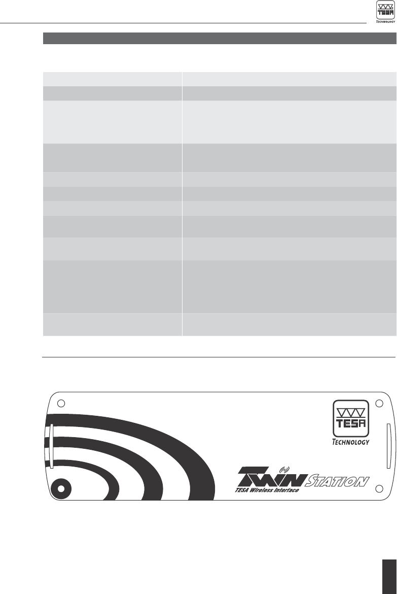
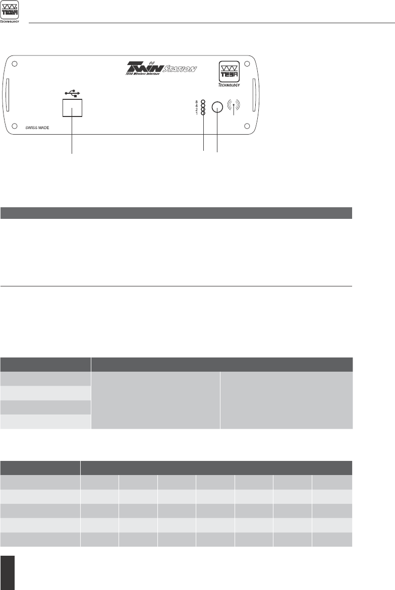
8.2 Elements at the front panel
Front panel of the TWIN Station
14
8.3 Elements at the rear panel
Rear panel of the TWIN Station
1 USB connector,
type B (to the PC,
USB multiplexer or
BPX box).
2
LEDs (box ID
number or error
message).
3
SMA antenna
connector, band
2.4 GHz.
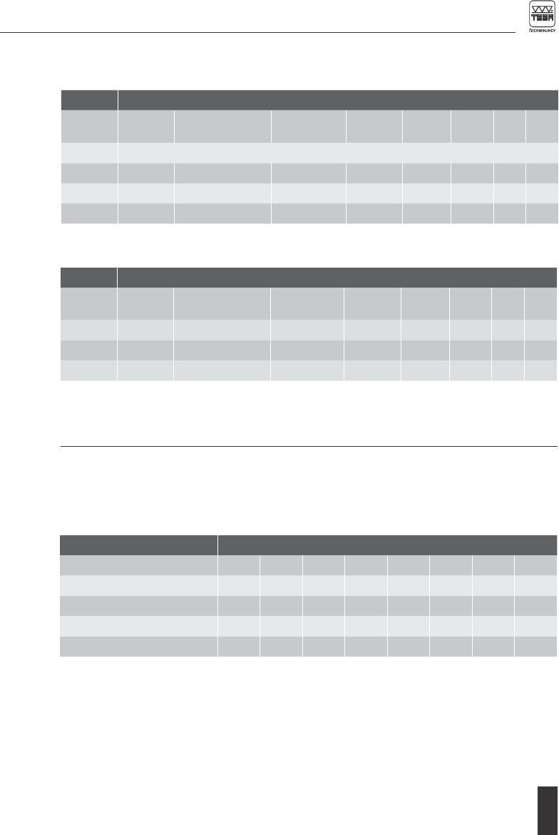
Interface boxes BPX44 in standard mode and TWIN Station Interface
LED 8 l ON / m OFF
Indicates the box ID number
(1 to 15)
All LEDs OFF = 16
k blinking
Indicates the number of the
relevant
error message (1 to 15)
LED 4
LED 2
LED 1
1 2 3
9 LIGHT EMITTING DIODES (LEDs)
The LEDs can either identify the interface box
or indicate a warning/error message. When the
BPX box operates in the stand-alone mode, they
indicate the status of the BPX box.
l LED is ON
m LED is OFF
k LED is blinking
9.1 LED status on both BPX box and TWIN Station
Every BPX box or TWIN Station can be iden-
tified by its ID number. The assignment of an
existing number to a replacement box makes
the maintenance easier while the measurement
programme remains unchanged.
Example
BPX44 in standard mode and TWIN Station
Box ID number 1 2 3 4 8 15 16
LED 8 m m m m l l m
LED 4 m m m l m l m
LED 2 m l l m m l m
LED 1 lmlmml m
15
E1 Power supply missing.
E3
BPX hardware problem.
E5 Corrupted probe memory (BPX).
E9 Fatal error, unexpected event.
E14 BPX or TWIN not initialized.
E15 USB communication error, driver
not installed.
A9 BPX in stand-alone mode: the USB cable is
connected, but the power supply is missing.
A11 BPX is in stand-alone mode, the set to
master has to be done as described in
chapter 7.5.2
9.2 Status of LEDs and output signals OUT on the BPX box used in stand-alone mode
LEDs indicate the operating status of the BPX box.
BPX44 in standard mode and TWIN Station
Error message number
E1 E3 E5 E9 E14 E15 A9 A11
LED 8 m m m k k k l k
LED 4 m m k m k k m m
LED 2 mkmmkkmk
LED 1 kkkkmkkk
9.3 LED status related to an error message
Both BPX box and TWIN Station have their own
status to indicate their operating status (and
error messages included). This status can be
requested through the PC. In case of error, the
box is regarded as the «slave».
Error messages
M1: Not used M2: Out of range, set to master failed
BPX44 in stand-alone mode
Stand-by
Set to
master to be done
Set to
master done
Rework Good Scrap M1 M2
LED 8 Default l ON m OFF if the IN1 signal is activated
LED 4 m m l m m l m l
LED 2 m k l m l m l l
LED 1 m k l l m m l m
Status of the OUT signals in stand-alone mode
Stand-by
Set to
master to be done
Set to
master done
Rework Good Scrap M1 M2
OUT 1 m l l l m m l m
OUT 2 m l l m l m l l
OUT 3 m m l m m l m l
M1: Incoherent pulse (too short or too long)
M2: 1 (or more) probes out of range during set
to master or measuring.
Stand-by means that the BPX is waiting
for a set to master or measuring command.

16
10 ASSEMBLY AND CONNECTION
The box may simply be placed onto a flat sur-
face. The rubber seal avoid slipping. The mount-
ing brackets available as an option allow for the
10.1 Assembly
box to be fixedly mounted on any surface or the
stacking of several BPX or TWIN Station.
Mounting brackets 05060009 (4 pièces)
05030012 TWIN Station
05030010 BPX
17
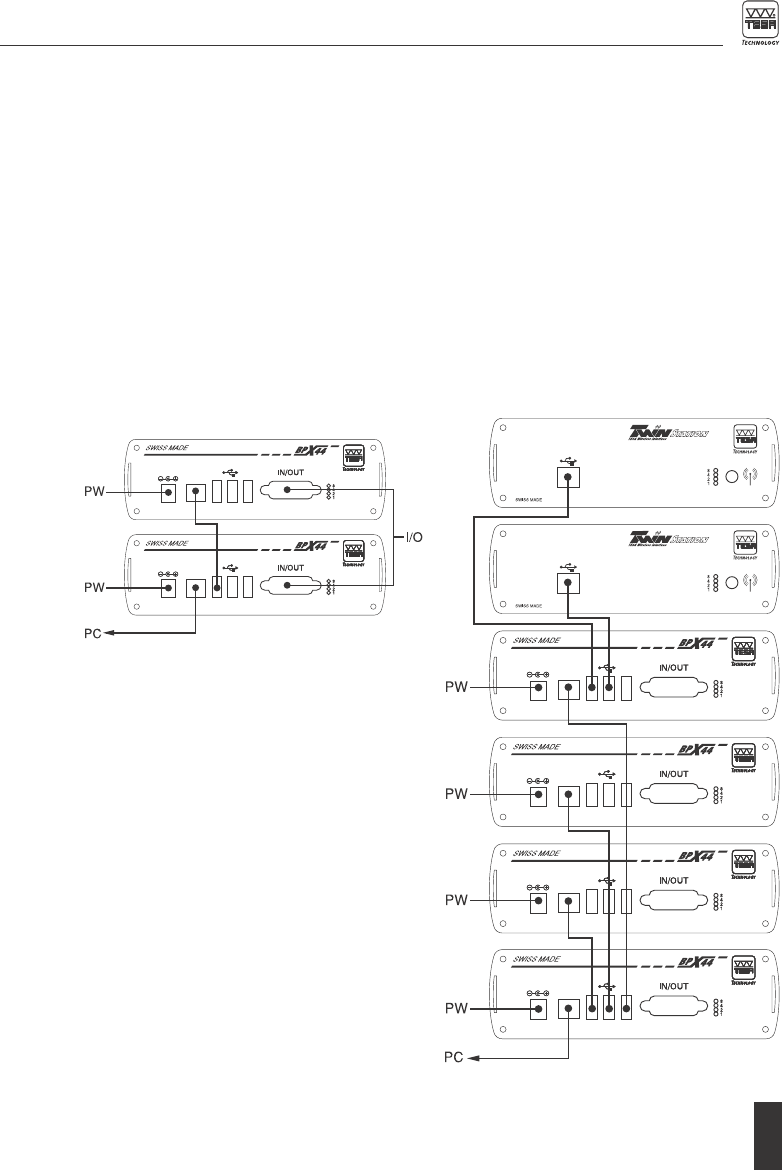
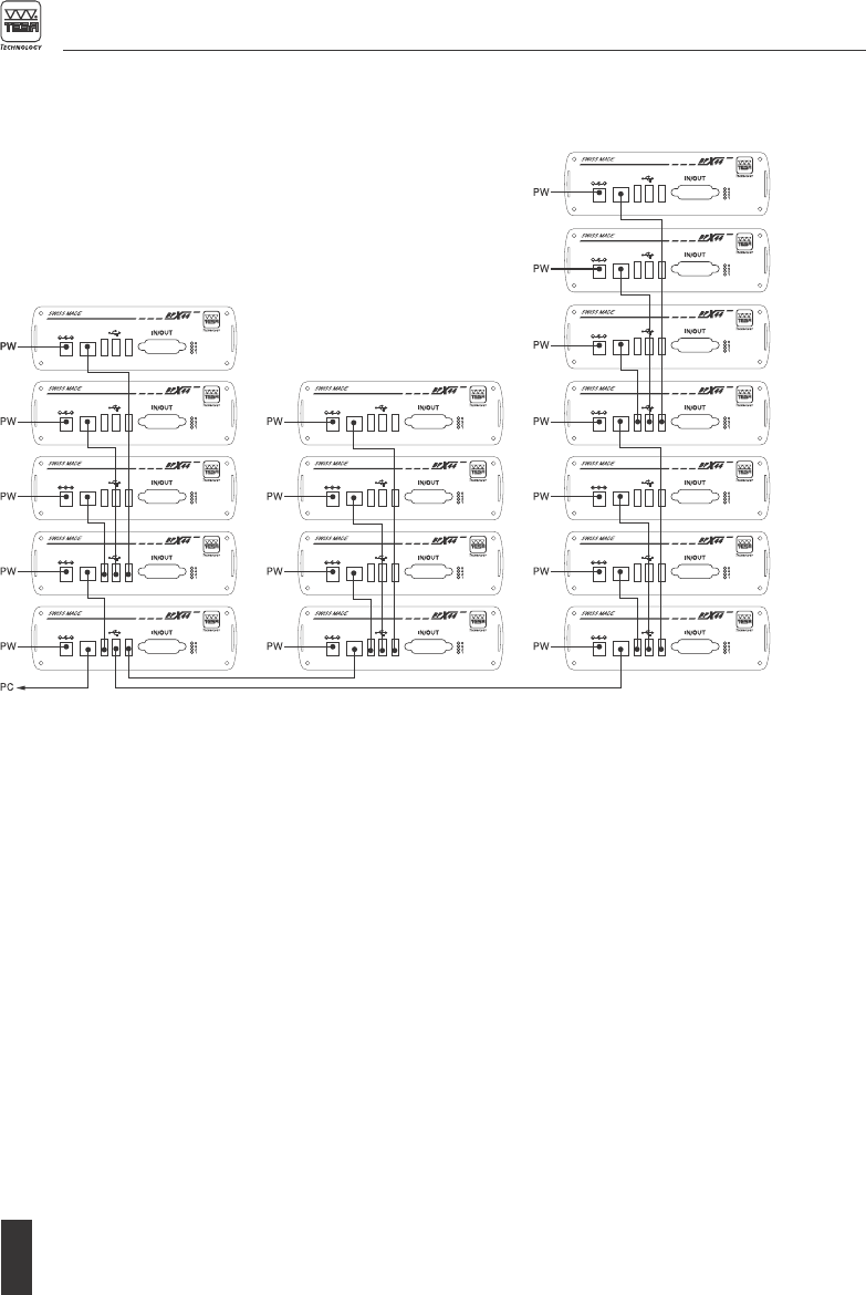
10.2 Connection
The connection is flexible, according to the
measurement application and the various loca-
tions. All BPX boxes in use must be individually
powered. Use only one connector for data trans-
mission to the PC to ensure the synchronization
of the boxes. Choose the parallel connection for
each box instead of a series connection that is
limited to 4 boxes only.
If only TWIN Station are used (without any BPX
box), connect them to a multiplexor USB-Hub.
Use then a single connector for data transmis-
sion from the USB-Hub to the PC, to ensure
their synchronization.
Connection of 2 BPX boxes
Remember to use the charger provided by TESA
for the power supply.
Connection of 4 BPX boxes and 2 TWIN Station
PW = Power Supply
18
Connection of 16 BPX boxes

19
11 RECYCLING
Each product must be treated separately. It is therefore important
to comply with the rules in force in your country as regards recycling.
12 GUARANTEE
We guarantee each product against any fault of design, manufacture or material for a period of
12 months from the date of purchase. Any repair work carried out under the guarantee is free
of charge. Our responsibility is limited to the repair of the relevant product or, if we consider it
necessary, to its free replacement.
The following are not covered by the guarantee: batteries and damage due to incorrect handling,
failure to observe the instruction manual, or attempts by any non-qualified party to repair the
product; any consequences whatever which may be connected either directly or indirectly with the
product supplied or its use.
(Extract from our General Terms of Delivery, December 1st, 1981)
13 DECLARATION OF CONFORMITY AND CONFIRMATION OF TRACEABILITY OF
ALL INDICATED VALUES
We thank you for your confidence in purchasing our products, which have been thoroughly checked
in our factory.
We declare under our sole responsibility that each product is in conformity with all technical data as
specified in our sales literature (instruction manual, leaflet, catalogue).
In addition, we certify that the measuring equipment used to check the products refers to national
master standards. Traceability of the measured values is guaranteed by our Quality Assurance.
Notice
For the USA and CANADA:
This device complies with Part 15 of the FCC Rules and with RSS-210 of Industry Canada.
Operation is subject to the following two conditions:
1. This device may not cause harmful interference, and
2. This device must accept any interference received, including interference that may cause undesi-
red operation.

20
Changes or modifications made to this equipment not expressly approved by TESA may void the
FCC authorization to operate this equipment. Radiofrequency radiation exposure Information:
This equipment complies with FCC radiation exposure limits set forth for an uncontrolled environ-
ment. This equipment should be installed and operated with minimum distance of 20 cm between
the radiator and your body. This transmitter must not be co-located or operating in conjunction with
any other antenna or transmitter.
This equipment has been tested and found to comply with the limits for a Class A digital device,
pursuant to Part 15 of the FCC Rules. These limits are designed to provide reasonable protection
against harmful interference when the equipment is operated in a commercial environment. This
equipment generates, uses, and can radiate radio frequency energy and, if not installed and used in
accordance with the instruction manual, may cause harmful interference to radio communications.
Operation of this equipment in a residential area is likely to cause harmful interference in which case
the user will be required to correct the interference at his own expense.
Under Industry Canada regulations, this radio transmitter may only operate using the antenna that
has been delivered by the manufacturer.
Quality Assurance

21
NOTES