TRUMPF Maschinen Austria KG 1701972-B wireless angle measuring equipment - Sensor User Manual
TRUMPF Maschinen Austria GmbH + Co. KG wireless angle measuring equipment - Sensor
User Manual

Retrofitting guide
TruBend Serie 3000, 5000 und 7000
Angle measuring system OCB (option)
2012-11-05
Material number: 1714400

2
1714400_ANGLE_MEAS
URING_SYSTEM_OCB

1714400_ANGLE_MEAS
URING_SYSTEM_OCB
Table of contents 3
Table of contents
1.
Description ........................................................................4
OCB radio measured value transfer device ...................5
2.
Installing the OCB transfer device ..................................5
LED status displays on the OCB radio
measured value transfer device .....................................6
OCB USB stick ..............................................................6
Registering the OCB transfer device at the OCB
USB stick .......................................................................7
DELEM machine control TruBend Series 3000 ............7
Activating the option ......................................................8
Installing an option ...................................................... 10
TASC6000 machine control TruBend Series
5000 and 7000 ............................................................ 11
Correction input mask for OCB .................................... 12
Direct total angle correction input ................................ 15
Global corrections ....................................................... 16
Complied rules and standards ..................................... 17
4
Description 1714400_ANGLE_MEAS
URING_SYSTEM_OCB
1. Description
OCB stands for Operator Controlled Bending.
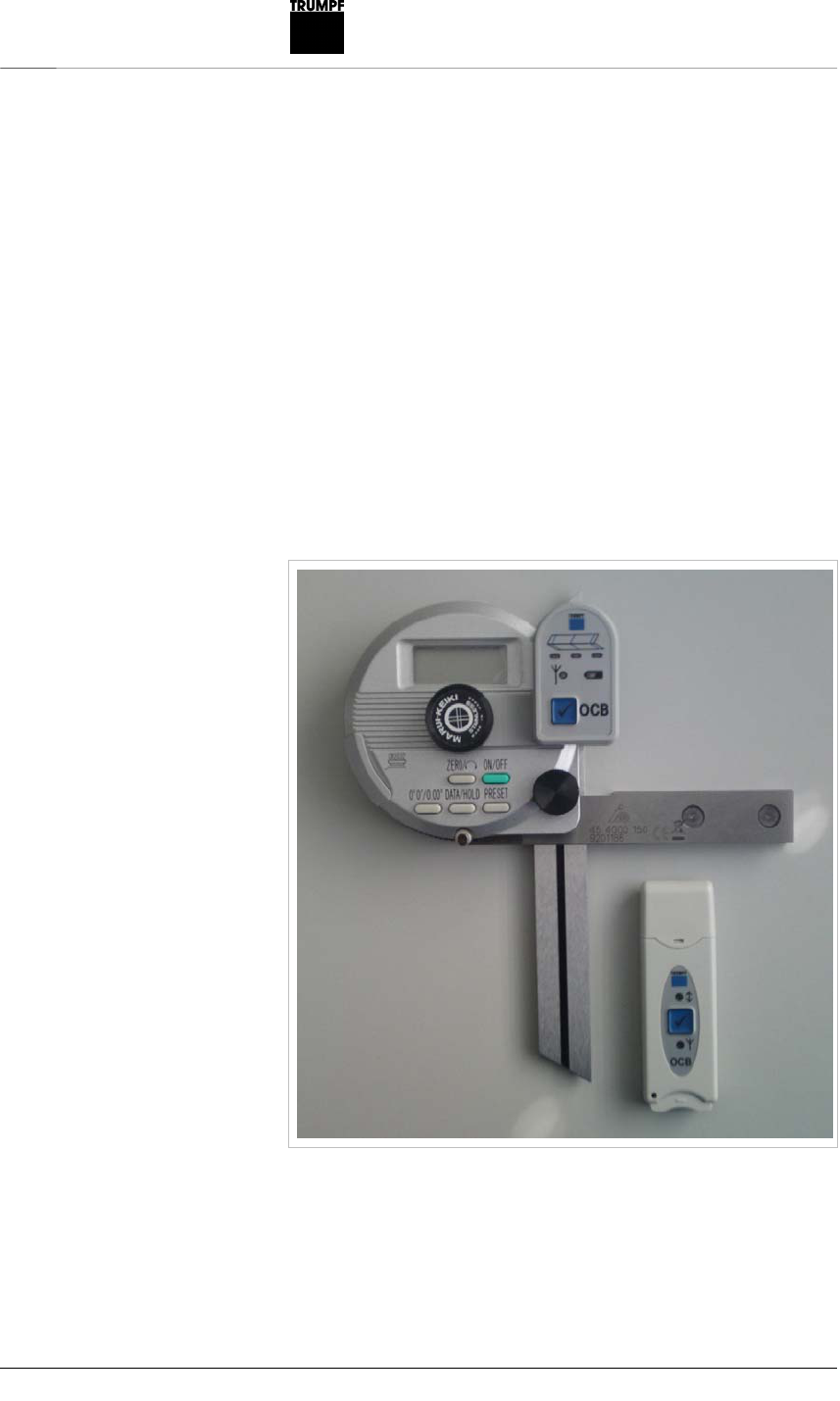
The complete OCB angle measuring system consists of the DP-
601 digital goniometer (ID no. 1701972) with the data output via an
interface as well as from the OCB radio measured value transfer
device, which is installed at the goniometer. There is also the OCB
USB stick, which is plugged into the machine control.
A paired radio measured value transfer system consisting of
transfer device and stick has the ID no. 1701972.
The hardware as well as the software of the OCB system can work
together with both the DELEM control system as well as with the
TASC6000 machine control. Two USB cables are included as
further accessories. All the parts of the OCB system are packed in
a stable ABS case with inserts made of punched foam parts with
the ID no. 1716453.
OCB system
Fig. 49843
1714400_ANGLE_MEAS
URING_SYSTEM_OCB
Installing the OCB transfer device
5
Both the OCB transfer device as well as the OCB USB stick
function as transmitter and receiver. The communication is
done by 2.4 GHz via the ISM band and can cover at line-of-
sight distances of about 20 meters.
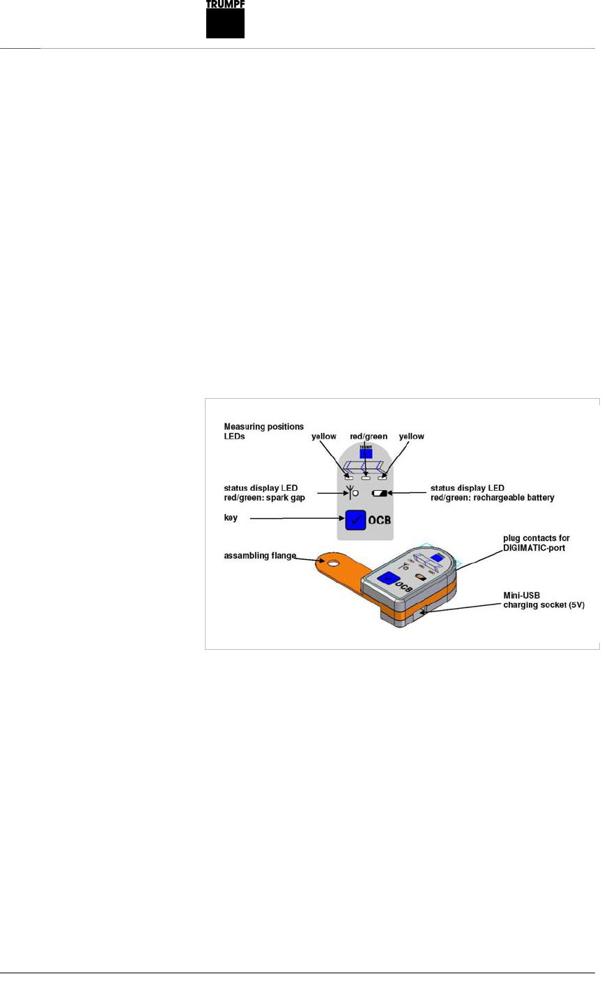
OCB radio measured value transfer device
By pressing the button, the angles shown on the goniometer will be
transferred to the control. The TRUMPF machine control
TASC6000 also specifies which of the three position LEDs at the
radio measured value transfer device should light up. The middle
LED is a dual-color LED (red/green). If both parts of the dual LED
are activated, the result is yellow. The left and right LEDs are
yellow. These three LEDs show the positions where the angles
should be measured in order to get the corrective values.
2. Installing the OCB transfer device
1. Pull off the rubber cover on the DIGIMATIC interface.
2. Unscrew the middle knob with the manufacturer's inscription.
3. Put on the transfer device and insert the plug contacts into the
DIGIMATIC interface.
4. Screw in the middle knob.
The knob now rests on the mounting tab.
Fig. 49844

6
Installing the OCB transfer device 1714400_ANGLE_MEAS
URING_SYSTEM_OCB
By using a 5-pole mini-B USB plug cable (even if the
transfer device is installed at the goniometer), the
rechargeable battery of the transfer device can be charged by any
standard 5-volt mobile phone charger or by any computer with a
USB socket. No data is exchanged by this USB connection; it is
only used to recharge the LiPo rechargeable battery. The transfer
device remains fully operative while it is being recharged.
LED status displays on the OCB radio
measured value transfer device
Rechargeable battery status Rechargeable battery
LED
The rechargeable battery and the OCB radio
measured value transfer device are both ready for
use
flashes slowly, green
The rechargeable battery is almost empty flashes slowly, red
The rechargeable battery is empty The device
switches itself off again immediately
flashes 1 second, red
The source voltage is plugged in and the
rechargeable battery is completely charged
lights up, green
The rechargeable battery can not be charged
since the temperature is too high or the battery is
defective
flashes quickly, red
The charging voltage is too low lights up, red
Radio transfer status Radio links LED
If the transfer was successful. flashes 1 second, green
If the transfer has failed after 5 attempts. flashes 1 second, red
If data is present from the goniometer and the
transfer is in progress.
flashes, yellow
If the goniometer is not switched on and, as a
result, no transfer is in progress.
after a short time
flashes 1 second, red
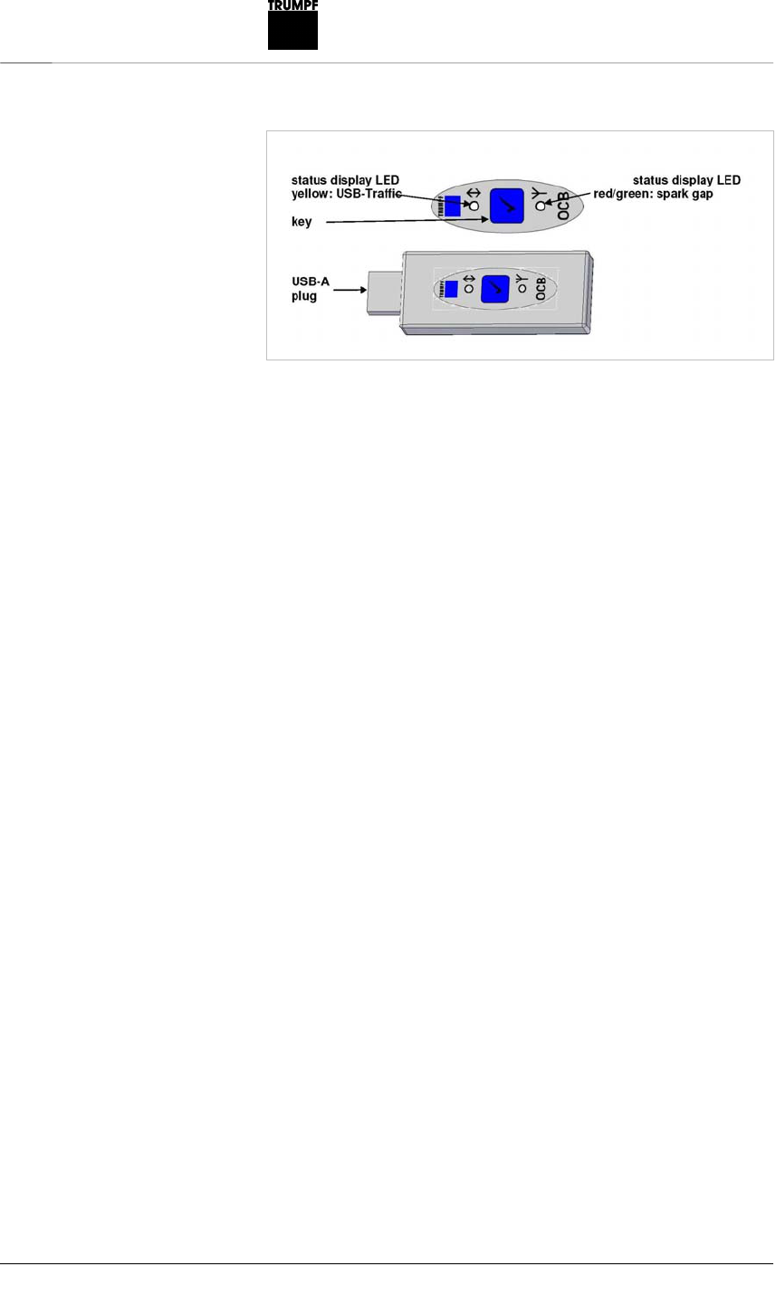
OCB USB stick
The USB stick (USB-A plug) receives the angle values,
administers the statuses of the position LEDs and the
registered OCB radio measured value transfer device and
prepares communication for the USB interface. The
communication is done via a virtual COM, which is created
by the FTDI-USB driver, with a baud rate of 57k6. USB traffic
is shown by flashing of the yellow LED.
Tab. 1
Tab. 2
1714400_ANGLE_MEAS
URING_SYSTEM_OCB
Installing the OCB transfer device
7
The OCB USB stick can, in principle, be plugged into any
USB plug socket of the machine control. However, USB plug
sockets outside the switch cabinet should be selected since
a closed switch cabinet significantly impedes radio signals.
The cap protects the plug from contamination. It is taken off
before plugging in and can then be put on again at the rear
for storage purposes during use.
Registering the OCB transfer device at the
OCB USB stick
Before delivery, all OCB systems are already paired. Every
OCB transfer device is already assigned in the factory to the
respective supplied OCB stick. For this reason, the
registering of the OCB transfer devices to OCB USB sticks
by the user is only necessary if new arrangements between
OCB transfer devices and OCB USB sticks are to be
established.
Up to 16 OCB transfer devices can be assigned to one OCB
USB stick. An OCB transfer device can be registered to
more than one OCB USB stick. The machine controls do not
participate in this registration procedure.
DELEM machine control
TruBend Series 3000
Note
Angle transfer by OCB for DA65TW control
is not possible.
Prerequisite for angle transfer by OCB
T3000 with software version ≥ V1.2.32.
Fig. 49845
8
Installing the OCB transfer device 1714400_ANGLE_MEAS
URING_SYSTEM_OCB
Activating the option
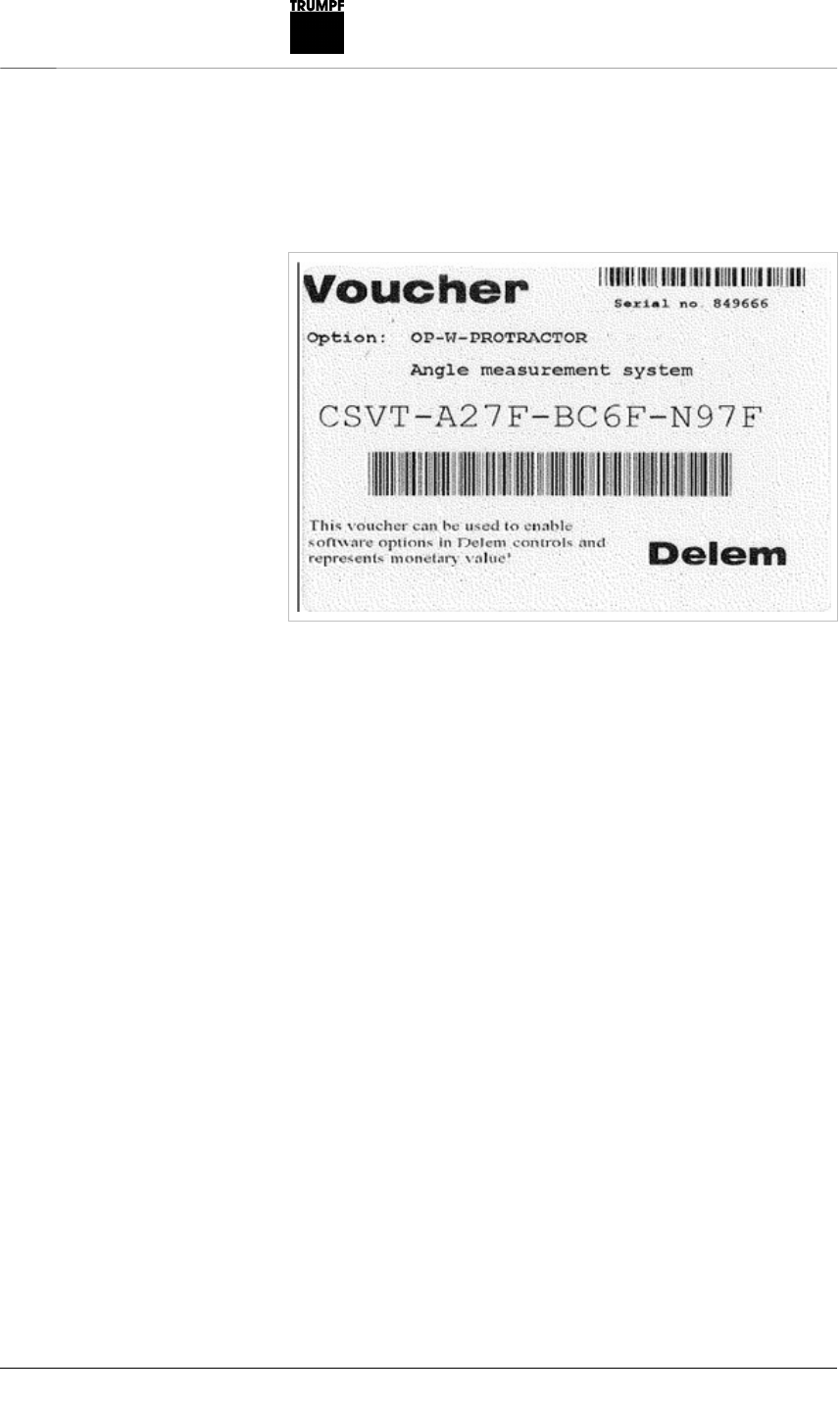
1. Check whether the option recognition OP-W-PROTRACTOR
and the brief description have been set.
Option voucher
2. When requesting an option, enter the identifier of the voucher
including the hyphens.
If an option for a control is requested, the control receives a license
for the requested option. From this moment on, the voucher and
the internal hard drive are linked. The voucher can not be used on
another control. In case required, the option can be requested
several times. In case an option is lost, the same option for the
same control can be requested again.
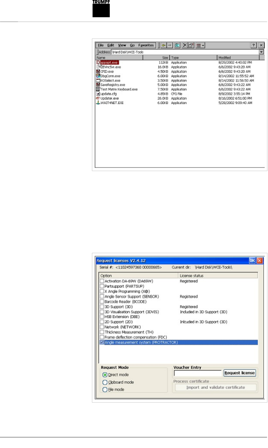
3. Switch to the Windows environment in the control.
4. Activate Windows Explorer in the start menu and change to the
"WCE Tools“ folder.
5. Activate the "appopt.exe“ application.
Fig. 49859
1714400_ANGLE_MEAS
URING_SYSTEM_OCB
Installing the OCB transfer device
9
The serial number of the control's internal hard drive is displayed
on the screen. On the left side of the screen, a list of the possible
options for the control is shown. An already activated option is
displayed by the word “Registered“ in the right column. The
procedure for the requesting of an option depends on the selected
mode. The “Direct mode“ selection is only possible if the control
has Internet access. If this is not the case, select “File mode“.
Activated program
Fig. 49860
Fig. 49861

10
Installing the OCB transfer device 1714400_ANGLE_MEAS
URING_SYSTEM_OCB
Installing an option
1. In the “Option“ field, click on the respective control element.
2. Select “File Mode“ in the “Request Mode“ field.
3. Enter the 16-digit voucher identifier for the option in the
“Voucher entry“ field and click on the “Generate UIR“ button.
A UIR text file is created which contains the code for requesting.
4. Send the UIR text file to TRUMPF Maschinen Austria.
5. Receive the license file from TRUMPF Maschinen Austria and
transfer it to a USB stick.
6. In the option program, select the requested option, select “File
mode“ and click on the “Import and validate certificate“ button.
7. In the file dialog that is now displayed, select the received
license file on the USB stick and click on “OK“.
If this is carried out successfully, the message “License
successfully imported“ is displayed and the license status changes
to “Registered“.
8. Click on “OK“ above in the window.
9. Change to the start menu and select “Suspend“.
The control carries out a restart.
10. Insert the OCB USB stick into a USB plug socket and restart
the control.
11. Select PROGRAMMED OPERATION.
12. At “11. Program data“, “Serial connection“, “Device for angle
measurement“, select Mit. 187-50x U-WAVE.
Note
The OCB USB stick must remain plugged in during the entire
transfer. In the event of interruption, a restart of the control has to
be done.
13. Measure the angle at the bending part.
14. Change to angle correction at the control.
15. Press the OCB button on the goniometer.
or
Press the DATA/HOLD button on the goniometer.
The green position LED lights up for a few seconds.
The displayed angle is transferred to the control. The LEDs on
the OCB transfer device and at the OCB USB stick light up
briefly.
16. Press ENTER.
Starting angle transfe
r
1714400_ANGLE_MEAS
URING_SYSTEM_OCB
Installing the OCB transfer device
11
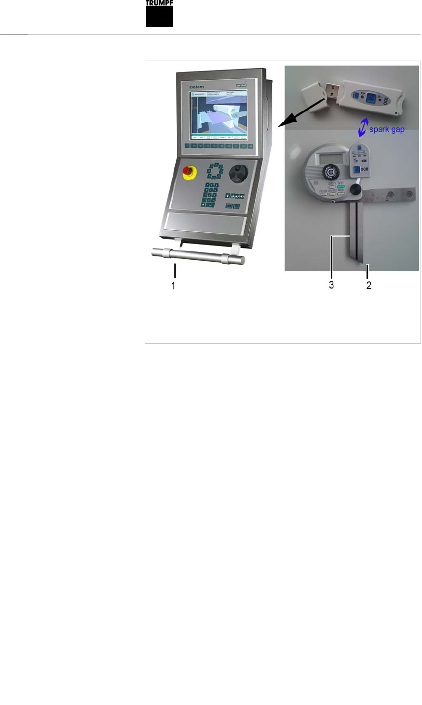
1 DELEM control system
2 Goniometer with radio measured
value transfer device
3 Adjustable side
Note
The goniometer has to be set to degree 0°0´/0.00° with the button.
It is so that the degree units as well as minutes and seconds can
not be determined via the goniometer interface. The direction of
rotation from the adjustable side [(3) Fig. 49846] has to be set in
such a way that the goniometer counts positively upwards in the
clockwise direction.
TASC6000 machine control
TruBend Series 5000 and 7000
Necessary versions
TruBend Series 5000 starting from V08.02
TruBend Series 7000 starting from V03.01
Activating of OCB
No option code is necessary for OCB with the TruBend Series
5000 and 7000. If the OCB USB stick is plugged into a USB
socket for these machine controls, then the OCB system will
be automatically activated.
Fig. 49846
12
Installing the OCB transfer device 1714400_ANGLE_MEAS
URING_SYSTEM_OCB
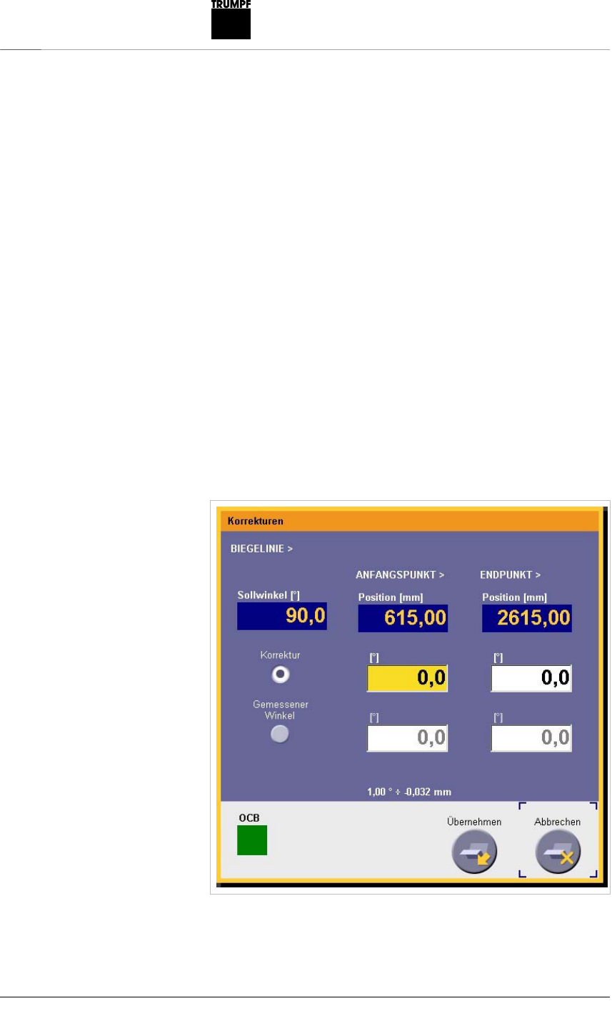
Correction input mask for OCB
The correction input mask for OCB is called up by the correction
buttons in production so that a bend that has just been performed
can be corrected whenever desired.
The two input fields for left and right corrective values (to enter the
measured angles) can be selected freely. The values can be
automatically entered with the OCB system or also manually with
the keyboard in the correction input box. The three measuring
position LEDs on the OCB broach are controlled by the selection of
the input fields for the measured angles.
Once an angle has been successfully transmitted by the radio link,
the next input field is selected right away in order to be able to
enter the angle there. In this way, the user can measure all
corrective angles and send them to the control without having to go
to the control after every angle measurement to manually switch-
over the input field at the control for the next angle input. If the red
LED lights up, then the measured angle is beyond the tolerance
range of ±10 degrees.
As an example, here an OCB application is run.
Entry of the left measured angle
Fig. 49853

1714400_ANGLE_MEAS
URING_SYSTEM_OCB
Installing the OCB transfer device
13
The left yellow LED of the radio measured value transfer device is
lit.
The control waits for the angle measurement. The actual angle is
transferred and the position LEDs are switched over. The user can
also simply enter this value by keyboard.
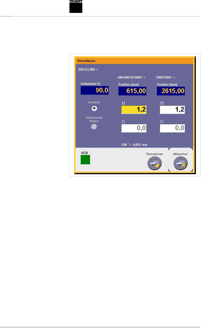
Entry of the right measured angle
Fig. 49854
14
Installing the OCB transfer device 1714400_ANGLE_MEAS
URING_SYSTEM_OCB
The right yellow LED of the radio measured value transfer device is
lit. The control waits for the angle measurement. The actual angle
is transferred and this LED goes out.
Transfer of the measured angle
All angles have been measured and successfully transferred. The
measured angles have to be confirmed by being accepted before
the Y1 corrective value and the Y2 corrective value are then
calculated from them. These corrective values are then saved in
the bending program. This input mask disappears and all LEDs are
then off, since no further input field has been selected for the
measure angle.
Fig. 49855

1714400_ANGLE_MEAS
URING_SYSTEM_OCB
Installing the OCB transfer device
15
Calculated corrective values
Direct total angle correction input
By focusing of the correction field in the production mask, all
position LEDs are automatically controlled at the OCB radio
transfer broach. In this way, it is shown that the angle to be
measured has no clearly defined position assignment. The
measured angle is then automatically taken over into this field as
correction and all the position LEDs flash as confirmation several
times briefly.
Corrective values in the production mask
Fig. 49856
Fig. 49857

16
Installing the OCB transfer device 1714400_ANGLE_MEAS
URING_SYSTEM_OCB
Global corrections
By focusing of the correction field in the global corrections mask
and selection of the appropriate nominal angle, all position LEDs
are automatically controlled at the OCB radio transfer device. In
this way, it is shown that the angle to be measured has no clearly
defined position assignment. The measured angle is then
automatically taken over into this field as correction and all the
position LEDs flash as confirmation several times briefly. All
nominal angles in this bending program with the displayed angle
value now receive this transferred corrective value.
Global corrective value for all 90° angles
Note
The goniometer has to be set to degree 0°0´/0.00° with the button.
It is so that the degree units as well as minutes and seconds can
not be determined via the goniometer interface. The direction of
rotation from the adjustable side [(3) Fig. 49846] has to be set in
such a way that the goniometer counts positively upwards in the
clockwise direction.
Fig. 49858

1714400_ANGLE_MEAS
URING_SYSTEM_OCB
Installing the OCB transfer device
17
Complied rules and standards
ISM-Band 2,405 GHz
EN300440, ReceiverClass3
EN30440-1 V1.6.1 (2010-08)
EN30440-2 V1.4.1 (2010-08)
EN301489-1+3
Radiated Susceptibility (Electromagnetic Field, modulated) (EN
61000-4-3)
Electrostatic discharge (ESD) (EN61000-4-2)
FCC Registration Number (FRN): 0021739461
Trade name: OCB-Stick
FCC ID Number: QYB-1701972-A
Trade name: OCB-Sensor
FCC ID Number: QYB-1701972-B
These two devices comply with Part 15 of the FCC Rules.
Operation is subject to the following two conditions:
(1) These two devices may not cause harmful interference,
and
(2) These two devices must accept any interference received,
including interference that may cause undesired operation.
Caution: Any internal changes or modifications of the two devices
named above void the user's authority to operate the equipment.

18
Installing the OCB transfer device 1714400_ANGLE_MEAS
URING_SYSTEM_OCB
DECLARATION OF CONFORMITY
We TRUMPF Maschinen Austria GmbH + Co. KG
Industriepark 24; 4061 Pasching; Austria
declare under our sole responsibility that the two products
Material number Product Title/Model
1701972-A OCB USB Stick OCB-Stick OCB-Stick
1701972-B OCB Wireless angle transfer device OCB-Sensor
to which this declaration relates is in conformity with the following
standards:
ISM-Band 2,405 GHz
EN300440, ReceiverClass3
EN30440-1 V1.6.1 (2010-08)
EN30440-2 V1.4.1 (2010-08)
EN301489-1+3
Radiated Susceptibility (Electromagnetic Field, modulated) (EN
61000-4-3)
Electrostatic discharge (ESD) (EN61000-4-2)
Following the provisions of R&TTE Directive 1999/5/EC
Pasching, 6th November 2012
(Place and date issue) (name and signature of
authorized person)