Contents
User Manual
1/14
GMRS-7000
USER MANUAL
2-WAY PORTABLE
HANDHELD
RADIO
DECEMBER, 20 , 2001
CONTENT
1.
GENERAL
1.1 General
1.2 Characteristic
1.3 Composition
2.
SPECIFICATION
2.1 General Specification
2.2 Electrical Specification
3.
OPERATION
3.1 ICON on LCD
3.2 Key Functions
3.3 Setting and Operation
2/14
4.
CHANNEL DATA
1. GENERAL
1.1 GENERAL
This equipment, GMRS-7000 is called 2 way portable handheld radio.
The frequency range is 462MHz, UHF operating Channel for international 2 way
radio. Also it has a 38 CTCSS feature to achieve the clear communication without
interference.
1.2 CHARACTERISTIC
a) All active device in this radio is composed of semiconductor and
high density IC.
b) CPU of this equipment is H8/3802 from HITACHI
c) Its power is operated by Ni-MH 7.2V battery.
1.3 COMPOSITION
This radio is composed of following.
a) Transceiver (W/Antenna)
b) Belt clip
3/14
2. SPECIFICATION
2.1 GENERAL SPECIFICATIONS
a) Frequency range : 462.5500 ~ 462.7250 MHz
b) Channel Frequency ( Weather ) : 161.6500 ~ 163.2750
c) Communication Mode : Half duplex
d) Channel Capacity : 15 channel
e) Channel Spacing : 12.5 kHz
f) Power : 7.2 V ( Ni-MH )
g) Battery Life : Alkaline. 9hours (Tx5%, Rx5%, Stand-by90%)
h) Operating Temperature : -30°C ~ +50°C
i) Dimension : 117(H) x 52(W) x 36(D) without antenna
j) Weight : 240.5g ( with battery ), 135.5g ( without battery )
2.2 ELECTRICAL SPECIFICATION
a) TRANSMITTER
1) Output power : Hi : 3.0W / Lo : 1.0W
2) Frequency Stability : ± 5 ppm
3) Modulation Method : FM
4) Oscillation Method : PLL SYNTHESIZER
5) Spurious Emission : < -60dBc
6) FM Hum/Noise : 35dB Min
7) Distortion : < 5% at 1 KHz
8) Current Drain : 1200 mA Max
b) RECEIVER
1) Sensitivity : 12dB SINAD
2) Selectivity : -50dB
4/14
3) Intermodulation : -50dB
4) Spurious and Image Rejection : -50dB
5) Audio Out Power : 300mW Max at 8 ohm
6) FM Hum & Noise : -45dB
3. OPERATION
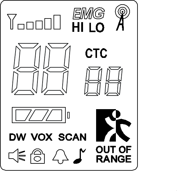
3.1 ICONS on LCD
1) Monitor indicator : Appears when the Monitor (M) button is pressed and the
channel monitor function is activated.
2) Key lock indicator : Appears when the keypad is locked. This function disables
keys such as channel up/down and MODE.
3) Beep ON/OFF indicator : Appears while key tone is in use and disappears
when tone is off.
4) Roger On/Off indicator : Appears while Roger tone is on, and disappears when
tone is not in use.
5) Battery indicator : Indicates the battery charge level.
6) Signal Strength Indicator : Appears when a signal is being received. The icon
5/14
consists of five bars to indicate the received signal level. The icon is also
represents transmit signal power during transmission.
7) Weather mode indicator : Icon will be on steady when in the weather band
mode. The Icon will blink in every 2 seconds when in the GMRS mode with the
alert active.
8) Hi/LO Indicator : Appropriate icon appears when the transmit power is set to
desired output power level.
9) Channel readout : Shows the channel number in use.
10) SCAN indicator : Indicates that scan is enabled.
11) CTCSS indicator : Appears when the CTCSS function is in use.
12) Dual Watch indicator : Appears when the Dual Watch function is in use.
13) Out Of Range indicator : Appears when the Out Of Range function is in use.
14) VOX (Voice Activated Transmission ) Indicator : This function allows hands
free conversation. The icon appears when the VOX mode is activated.
16) Emergency Indicator : EMG Icon appears when the EMG button is pressed (
The frequency is NOT monitored by authorities ).
3.2 Key Function
M ODE
SCA N
EMG
1) PTT Button : Push and hold to transmit ; release to receive.
2) Monitor Button : This button is used to check activity on the current frequency
before transmitting.
3) Up/Down key : In the stand-by mode, Pressing this button will increment or

6/14
decrement the listening volume.When in function edit mode,
this button will be used to adjust the unit's settings..
4) Scan / Lock key : Press this button momentarily to enable or disable the
scan mode. Press and hold the button for over 2seconds to lock
or unlock the keypad.
5) Mode (Function) key : Push to select the following function setting mode.
Βριεφ πρεσσ µοδε : 1∋στ πρεσσ Χηαννελ ,
2 νδ πρεσσ ΧΤΧΣΣ,
3 ρδ πρεσσ Ποωερ Ηι / Λο
4∋τη πρεσσ ςΟΞ λεϖελ
5 τη πρεσσ ∆υαλ Ωατχη
6∋τη πρεσσ Ρογερ Βεεπ
7 τη πρεσσ Βεεπ Τονε
8 τη πρεσσ Χαλλ
6) Emergency ( EMG ) Call Button : This radio has a quick access button( EMG ) to
the Emergency and Assistance Channel. This channel is not monitored by
local authorities. When using this channel, EMG appears on the display.
Pressing this button will set the transceiver to the channel 10
7) Speaker / Microphone
8) LCD (Liquid Crystal Display)
9) Transmit / Receive indicator : When receiving an incoming signal, the LED
indicator will light green, and while the PTT
button is pressed, the LED will light red.
These LED’s are used for backlighting as
well.
10)External speaker/mic jacks : Connect an optional speaker/mic or headset,
if desired. The internal mic and speaker will not
function when either one is connected.
2) Function display
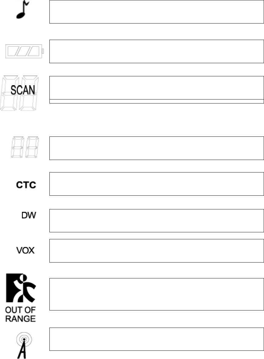
Monitor Indicator: Icon appears when the monitor button is pressed and the channel
monitor function is activated.
Key Lock Indicator: Icon appears when the keypad is locked. This function
disables keys such as channel up/down and mode.
Signal Strength Indicator: Icon appears when a signal is being received. The Icon
consists of five bars to indicate the received signal level.
Beep Tone Indicator: Icon appears when beep tone confirmation tone is selected.
Icon disappears when tone is off.
7/14
3-3. SETTING AND OPERATION
Roger Beep Tone On/Off Indicator: Icon appears when the roger beep tone is
selected. Icon disappears when tone is off.
Battery Level Indicator: Icon indicates the battery charge level.
Large Segment Display: Indicates the channel number in use.
Coded Tone Controlled Squelch System(CTC) Indicator: Icon appears when the
CTCSS tone function is active.
Small Segment Display: Displays CTCSS tone option in the channel from 00 to 38,
and also displays the caller ID number(01–10) when caller ID function is active.
Scan Indicator: This function allows users to scan a channel to search for a valid
signal.
Dual Watch mode Indicator: Icon appears when dual watch mode is active.
Voice Activated Transmission (VOX) Indicator: This function allows handsfree
conversation. The Icon appears when the VOX mode is activated.
Out of Range Alarm Indicator: Icon blinks as the receiving signal is getting weaker.
The Icon stops blinking when the receiving signal comes back to the normal
strength.
Weather Mode Indicator: Icon will be on steady when in the weather band mode.
The icon will blink when in the GMRS mode with the alert active.
8/14
In order to communicate with other GMRS/FRS units, both you and the
receiving party must be on the same channel.
GMRS-7000 has 15channels indicated by the large digits on the
LCD display panel. Before trying to transmit on the selected channel,
you should press the Monitor Button to check the activity on that channel.
If someone is already on the selected channel, you should try another
channel which is clear
1) On/Off & Volume control Switch
Radio ON : Press the power button at least for 2 seconds.You will hear
confirming melody to indicate the unit is on.
Radio OFF : Press the power button at least for 2 seconds.
Volume setting : Press up[″]or down[…] button to adjust a level comfortable
for you while monitor is active.
2) Setting the Channel and Tone Code(CTCSS)
GMRS-7000 has 15 main channels and 38 sub-channels.
! 14 Frequency channels
! 38 CTCSS Code ( indicated by CTC icon on the LCD )
To select the channel
! Turn the radio on.
! Press MODE button once, [XX] digit will blink on the LCD. XX is a
channel.
! Press up[″]or down[…] button to choose the channel.
! Press the PTT button or MODE button to confirm.
To set the tone codes(CTCSS)
! Press MODE button once more, [XX oF, 01 up to 38] will appear and CTC
icon and tone code digit will blink on the LCD. “oF” means no CTCSS
code.
! Press up[″]or down[…] button to choose the desired sub-channel to use.
! Press the PTT button or MODE button to confirm.
NOTE : To communicate with other GMRS/FRS units, they must
be switched to the same channel and CTCSS sub-code. To
communicate with other GMRS/FRS units which do not have sub-
codes, switch your unit to the same channel with the sub-code setting
to OFF.
3) VOX (Voice Operated Switching)
This option enables you to have hands-free conversation. You do not have to
operate the PTT button each time when you want to transmit.
You can also choose the VOX sensitivity suit your environment of operation.
( Ex : noisy road, motor bike, factory etc. )
To Set the VOX mode
! Press the MODE button until the [Uo oF or XX] appears. XX is a vox level
9/14
! VOX icon will be appeared on the LCD.
To set the VOX level
! Press the up[″]or down[…] button to set the VOX level from 1 to 5.
“oF” is disable the VOX function.
“01” is least sensitive.
“05” is most sensitive.
! Press the PTT button or MODE button to confirm.
4) Setting the DW (dual watch)
To set the DW mode
! Press the MODE button until the [ oF of 01 up to 15] and DW icon blink
on the LCD.
! DW icon will appear on the LCD.
To set the dual watch(DW) channel
! Press the up[″]or down[…] button to choose the channel.
“oF” means no DW mode.
“01 up to 15” means the channel is dual-watched.
! Press the PTT button or MODE button to confirm.
5) Power Selection Mode
This feature permits selection of the transmitting power level to high or low.
Using low power, the unit will have a lower transmit range but battery life will
Be increased.
To access the transmitter power selection function
! Press the MODE button until the Po icon appears with a flashing Hi or Lo
indication on the display.
! Press the Up or Down button to toggle between the Hi or Lo selections.
! Press the PTT button momentarily to confirm selection.
6)Roger tone
This feature will give the tone signal to other parties when transmitting is
finished
(when PTT button is released.)
To activate or disable the Roger tone
! Press the Mode button until [rb On or oF] and the roger icon blink on the
LCD.
! Πρεσσ τηε υπ[″]ορ δοων[…] βυττον.
! Press the PTT button or MODE button to confirm.
10/14
7) Beep tone
Hearing this tone, users will make sure that any button has been correctly
pressed.
To set the beep tone
! Press the Mode button until [bP On or oF] and the BELL icon blink on the
LCD.
! Press the up[″]or down[…] button.
! Press the PTT button or MODE button to confirm.
8) Call Ringer Selection Mode
This feature Provides 3 user selectable call ringer signal.
To set your favorite call ringer signal.
! Press the MODE button until the [C 01 or up to 03] appears on the LCD.
! Press the up[″]or down[…] button to select the call melody type.
! Press the PTT button to confirm.
! To activate the call, click the “PTT” button twice quickly.
9) Out-of-range Alarm
Icon blinks as the receiving signal is getting weaker. The Icon stops blinking
when the receiving signal comes back to normal strength.
10) Transmitting
! Press and hold the PTT button (The LED light red during transmission.)
! Speak slowly and clearly
! To Stop the transmission, release the PTT button.
! If there is no more receiving signal for 5 seconds, the unit will go into
power save mode.
11) Receiving
The Coding feature reduces the possibility of interference and provide
enhanced Communication. You can only listen to a call which has correct
matching codes.
** Upon receiving a signal, the LED will light green. In case that a signal, which
has different CTCSS channel, is received when the Radio is on the CTCSS mode,
the LED blinks in green.
Important :
Before transmitting or receiving, the users have to make sure that the correct
channel ( 1 to 15 ) and code ( 00 to 38 ) are selected.
12) Channel Scanning
11/14
This feature allows you to monitor all activated channels while scanning.
To activate the Scan
! Press the SCAN button
! Radio will begin scanning.
! When in scan mode, the display will show each scanning channel.
! After an activated channel is scanned, a signal will be received. If there is
no more signal, the scan will resume automatically.
** If a channel is scanned, a user can resume the scan by pressing the monitor
button.
13) Call
! Click the PTT button twice quickly.
14) Monitoring the Channel
It is used to check activity on the current frequency before transmitting.
To activate the monitor feature
! Press and hold the “M”(monitor) button for over two seconds.
! You will hear static if frequency is clear.
( The monitor icon will appear on the LCD.)
To disable the monitor feature
! Press and hold the “M”(monitor) button for over two seconds.
( The monitor icon will disappear on the LCD.)
15) Keypad Lock
The lock function is to avoid the accidental channel change to the preferred
settings of the unit. All buttons will be locked except the Power, PTT, Monitor,
Volume UP/Down.
To lock the keypad
! Press and hold the “SCAN” button for over two seconds.
! Keypad will be locked (LOCK icon will appear on the LCD)
To unlock the Auto Key function
! Press and hold the “SCAN” button for over two seconds.
! Keypad will be unlocked (LOCK icon will disappear on the LCD)
3-4. SETTING AND OPERATION ON WEATHER BAND
1) Channel Selection
This feature provides access to 10 channels within the weather band(7 NOAA
channels and 3 Canadian marine channels. To select a weather channel, the unit
must be in the weather channel mode. Press and hold the MODE button for at
least 2 seconds, the weather alert icon(A ) will appear, together with a channel
12/14
number in the band. Press the mode button until the channel number flashes.
To change the channel,
! Press the Up button briefly to move to the next higher main channel
number.
! Press the Down button briefly to move to the next lower main channel
number.
2) Weather Alert Mode
The weather alert mode notifies the user of unusual weather situations. To
access the weather alert function:
! From weather band standby mode, press the mode button once to access the
weather channels and use the Up or Down button to select the desired
channel.
! Press the mode button again to access the weather alert function; weather
icon(A) and AL On or oF appear flashing on the display.
! Use the Up or Down button to enable(On) or disable(oF) the alert function.
The weather icon will stop blinking on the display when the alert is
disabled.
! Press the PTT button to confirm your selection
! Press and hold the mode button for at least 2 seconds to exit the weather
function.
When the unit is in GMRS/FRS, if a weather alert signal is received, the unit
will generate a warning tone. The weather alert tone will be generated for 2
seconds and the unit will then automatically revert to a previously selected
weather channel.
3-5. Battery status indicator
The Battery icon will blink when the radio is in low battery power. The alarm
tone will beep once in 10 seconds. Then charge the rechargeable batteries or
replace the batteries.
! Full battery – three segments are displayed.
! Low battery – the battery icon(only the rim) blinks.

13/14
4. CHANNEL DATA
1) GMRS Frequency Chart
Channel Frequency (MHz) Channel Frequency (MHz)
1 462.5625 8 462.5750
2 462.5875 9 462.6250
3 462.6125 10 462.6750
4 462.6375 11 462.5500
5 462.6625 12 462.6000
6 462.6875 13 462.6500
7 462.7125 14 462.7000
15 462.7250
2) CTCSS Tone Frequency Chart
NO FREQ.(Hz) NO FREQ. (Hz) NO FREQ. (Hz)
1 67.0 14 107.2 27 167.9
2 71.9 15 110.9 28 186.2
3 74.4 16 114.8 29 179.9
4 77.0 17 118.8 30 186.2
5 79.7 18 123.0 31 192.8
6 82.5 19 127.3 32 203.5
7 85.4 20 131.8 33 210.7
8 88.5 21 136.5 34 218.1

14/14
9 91.5 22 141.3 35 225.7
10 94.8 23 146.2 36 233.6
11 97.4 24 151.4 37 241.8
12 100.0 25 156.7 38 250.3
13 103.5 26 162.2 OF 0
3) Weather Channel Frequencies:
Channel Freq. MHz Channel Freq. MHz
1
2
3
4
5
162.550
162.400
162.475
162.425
162.450
6
7
8
9
10
162.500
162.525
161.650
161.775
163.275