Tadano RCSFT1-433 Remote Control Transmitter User Manual UserManual
Tadano Ltd. Remote Control Transmitter UserManual
UserManual.wiki
>
Tadano
>
RCSFT1 433 User Manual
UserManual
Navigation menu
Upload a User Manual
Namespaces
Wiki Guide
HTML
PDF
Info
Views
User Manual
Discussion / Help
Navigation

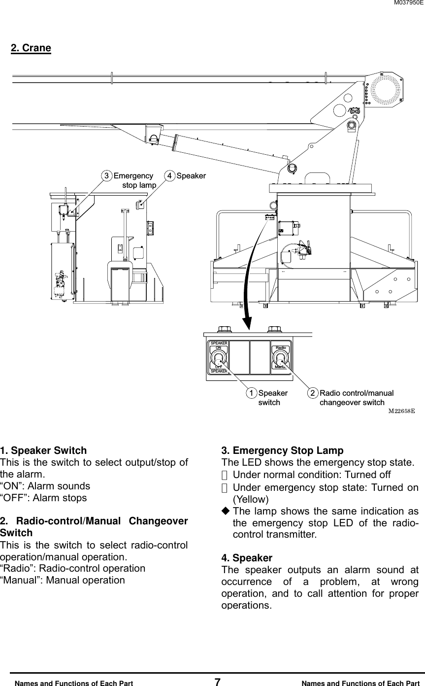

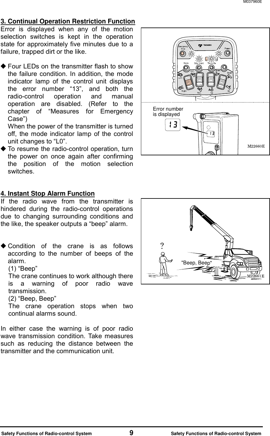
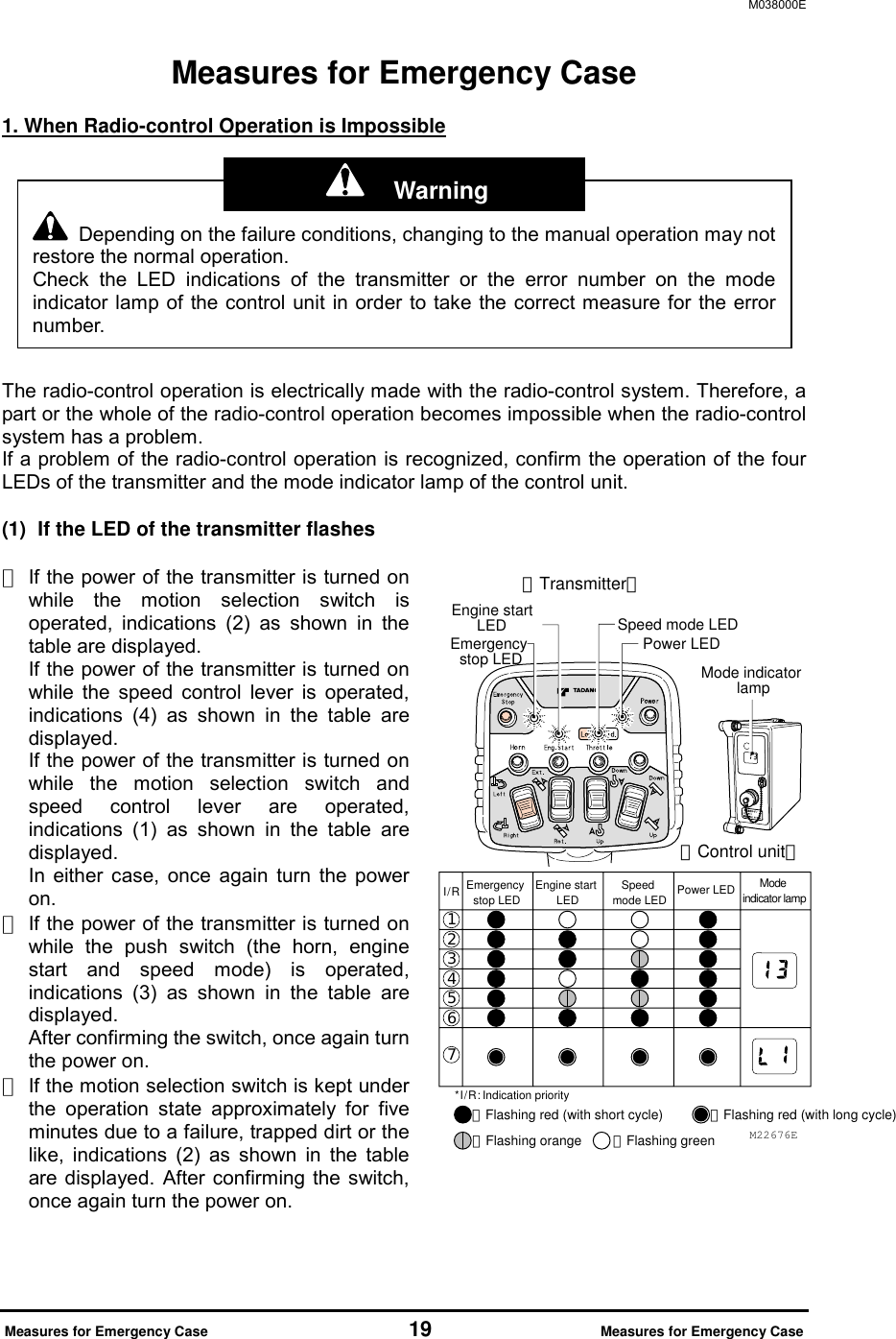
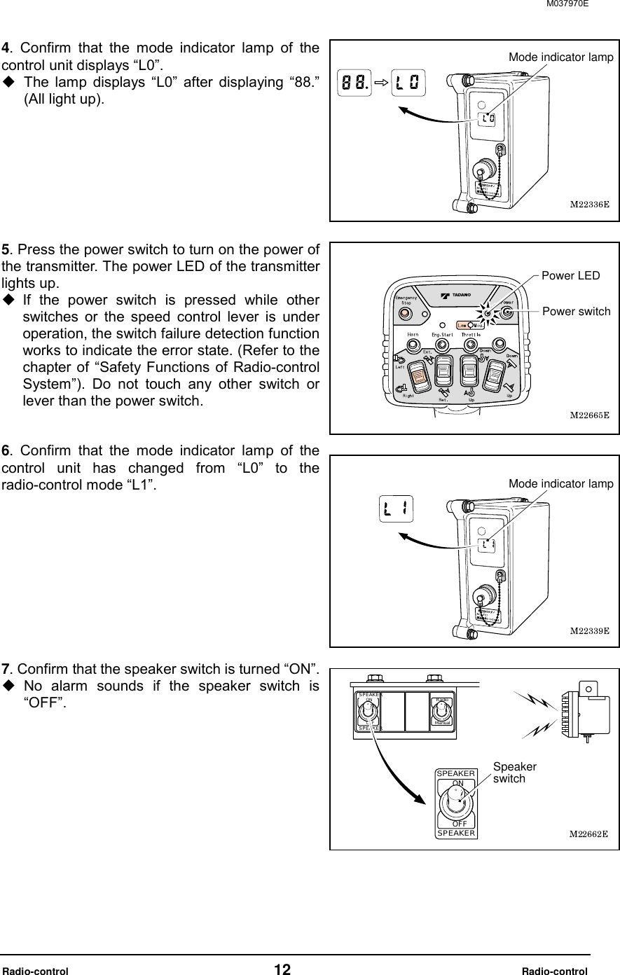
![M037970E Radio-control 11 Radio-control Radio-control [NOTE] Even after the radio-control transmitter is turned OFF under the condition where the radio wave is out of reach, the control unit still remains on in the radio-control mode. Make sure to confirm that the mode indicator lamp of the control unit indicates “L0” after the radio-control operation is completed (or after the power of the transmitter is turned OFF). 1. Preparation for Radio-control Operation Confirm that each lever is at the following position before starting up the engine. Each operation lever for extension/winch/elevation/swing/jack ••••• “Neutral” PTO lever (Switch) ••••• “Disconnected” Operation mode changes as is shown in the figure according to the PTO operation, operation of the radio-control /manual changeover switch, and power ON/OFF of the radio-control transmitter. In addition, an indication on the mode indicator lamp of the control unit changes as the figure shows. 1. Start up the engine and turn PTO to “Connected (ON)” position. Confirm that the radio-control /manual changeover switch is on “Manual” position. 2. After extending the outriggers, extend the jacks and set the crane level. 3. Turn the radio-control /manual changeover switch to “Radio” position. When the switch is turned to “Radio” position, the power of the control unit is turned ON. Radio-control/manual changeover switchM22663 ](https://usermanual.wiki/Tadano/RCSFT1-433/User-Guide-2225291-Page-12.png)

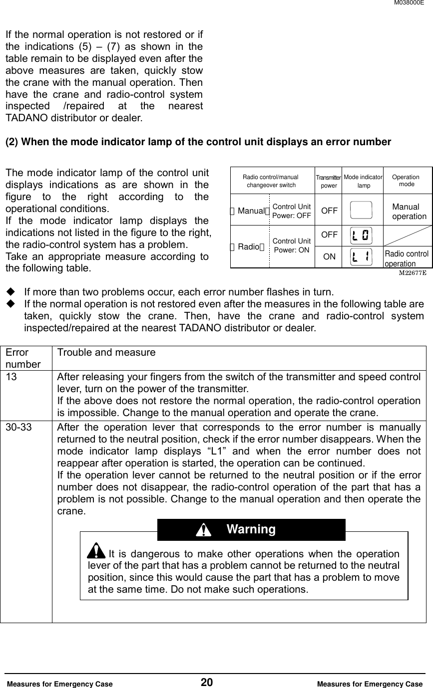
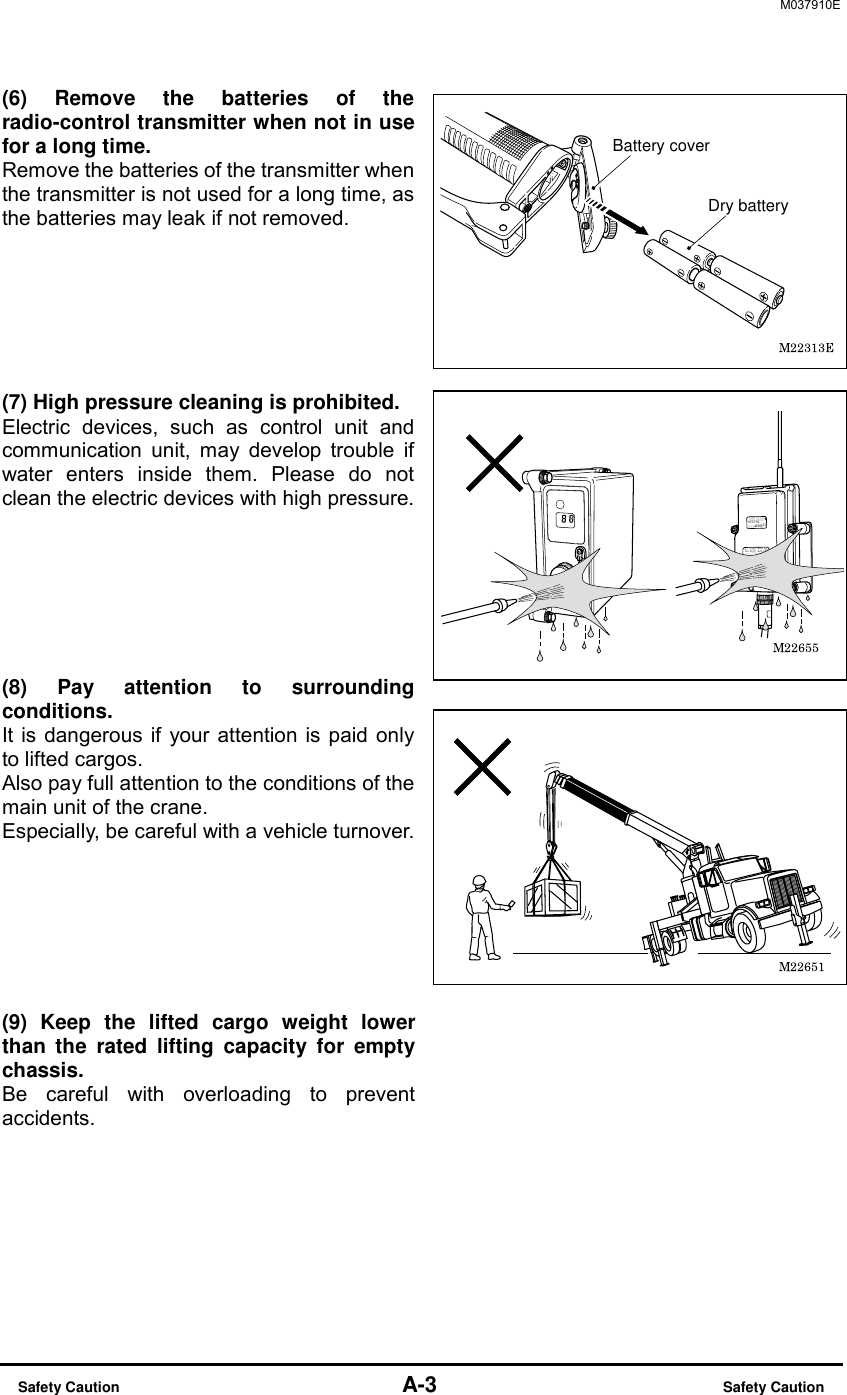
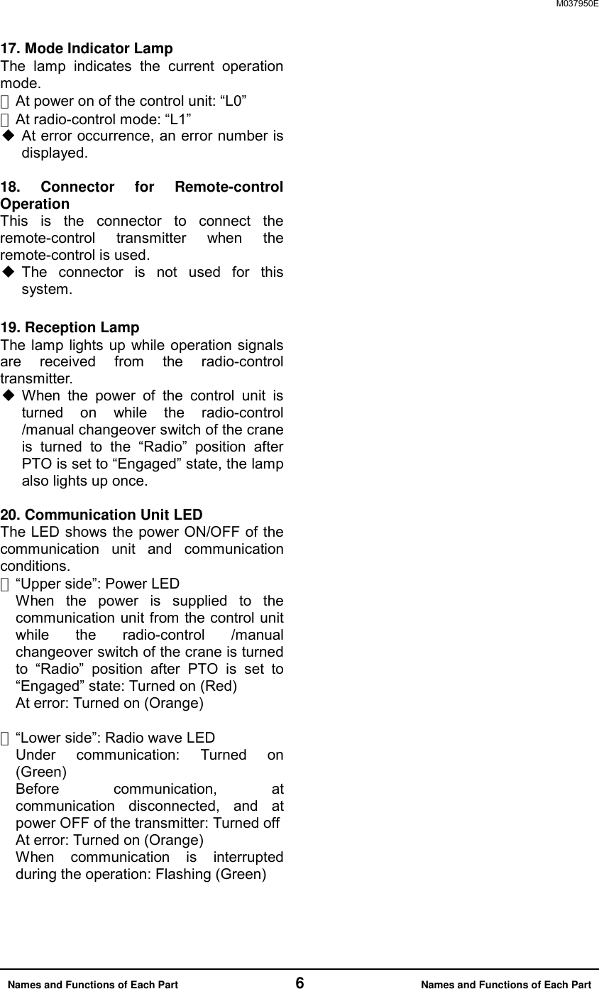
![M037970E Radio-control 16 Radio-control 4. Engine Start-up Operation [NOTE] Engine start-up operation is disabled under the emergency stop state. Release the emergency stop state before the operation. Press the engine start switch after conforming that the engine is stopped. The engine start LED lights up while the switch is pressed and the engine starts. After the engine starts up, quickly release your finger from the switch. 5. Emergency Stop Operation When the control cannot be made through the radio-control operation, or when the surrounding situation becomes dangerous, press the emergency stop switch. If the switch is pressed, the engine stops, which stops the crane operation. When the switch is pressed, the emergency stop LED and emergency stop lamp of the crane light up to indicate the emergency stop state. Beep alarm sounds. How to Release Emergency Stop Press the switch once again. Then the emergency stop LED and emergency stop lamp of the crane turn off and the emergency stop state is released. Two-tone alarm sounds. The emergency stop state is also released when the switch of the control unit is turned off after the radio-control /manual changeover switch is turned to “Manual” position. It is dangerous to start up the engine while the motion selection switch of themanual operation lever or transmitter is under operation, causing suddenmovement of the crane. Start-up the engine after confirming that the operationlevers and motion selection switches are in the neutral position. The engine is damaged if the starting-up operation of the engine is made whilethe engine is rotating. Start-up the engine after confirming that the engine hasstopped. Engine start LEDEngine start switchEmergency stop LEDEmergency stop switch Warning](https://usermanual.wiki/Tadano/RCSFT1-433/User-Guide-2225291-Page-17.png)
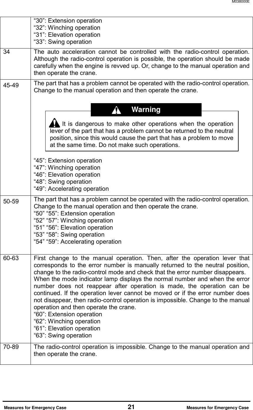
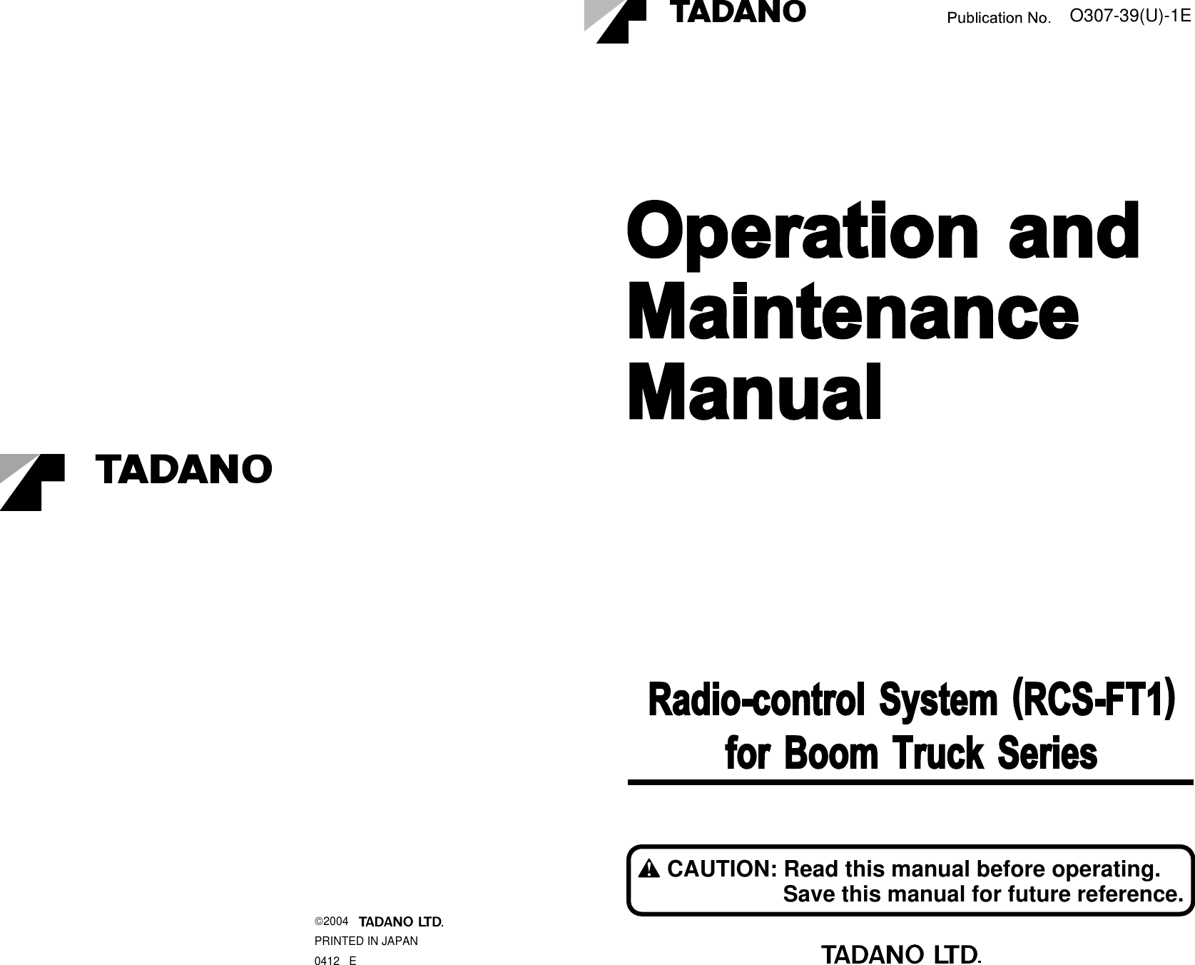
![M037980E Manual Operation 17 Manual Operation Manual Operation [NOTE] To change from the radio-control operation to manual operation, turn off the power of the radio-control transmitter, and then turn the radio-control /manual changeover switch to the “Manual” position. Even after the radio-control transmitter is turned off under the condition where the radio wave is out of reach, the control unit still appears to be on, in the radio-control mode. Make sure to confirm that the mode indicator lamp of the control unit indicates “L0” after the radio-control operation is completed (or after the power of the transmitter is turned off). Power LED (Turned off) Power switch RadioManualRadio-control/manual changeover switchPTOTransmitterpowerMode indicator lampRadio-control/manual changeover switchONManual operationRadio-control operationOFFManualON OFFRadioON ONRadioOperation modeMode indicator lamp](https://usermanual.wiki/Tadano/RCSFT1-433/User-Guide-2225291-Page-18.png)
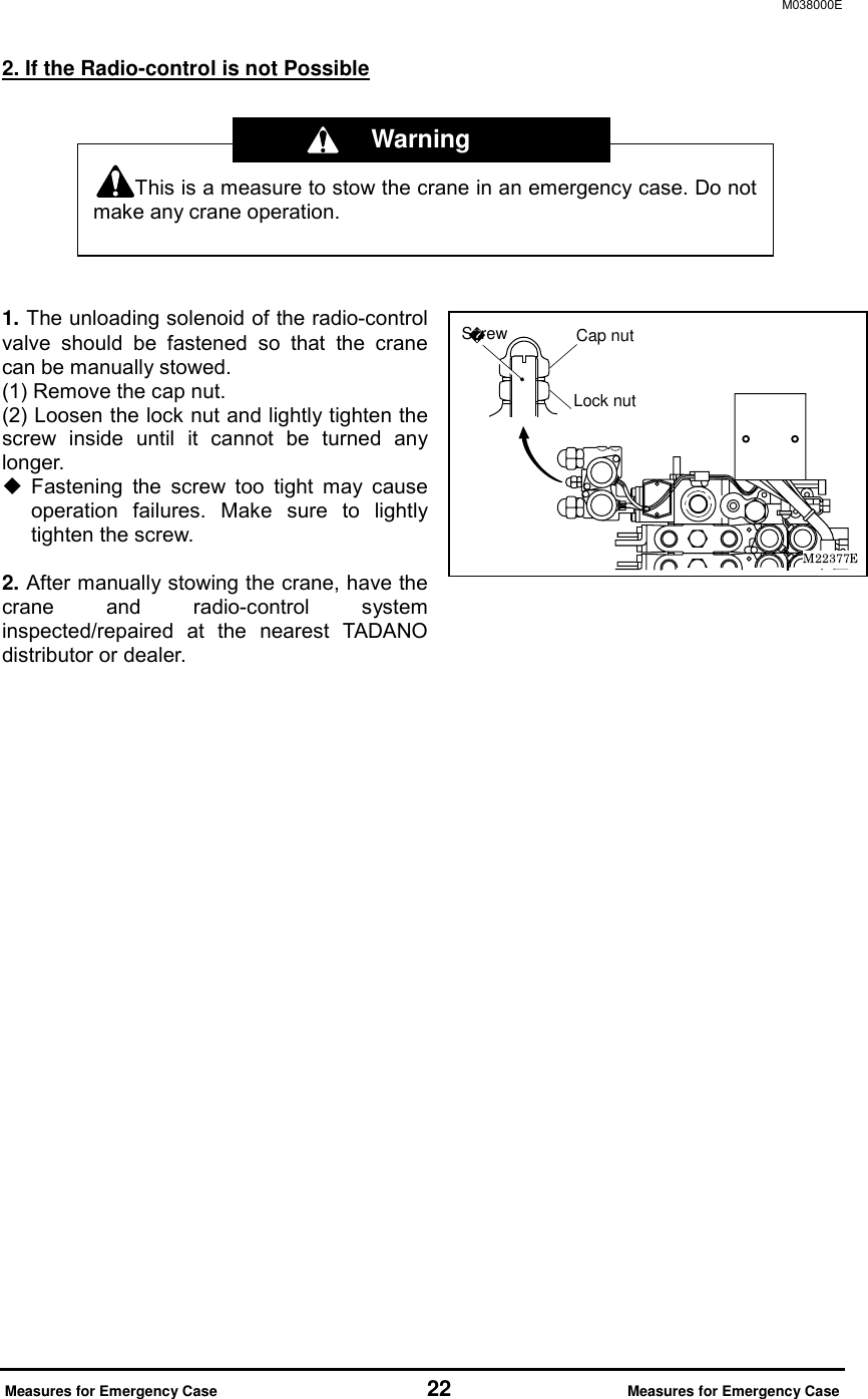
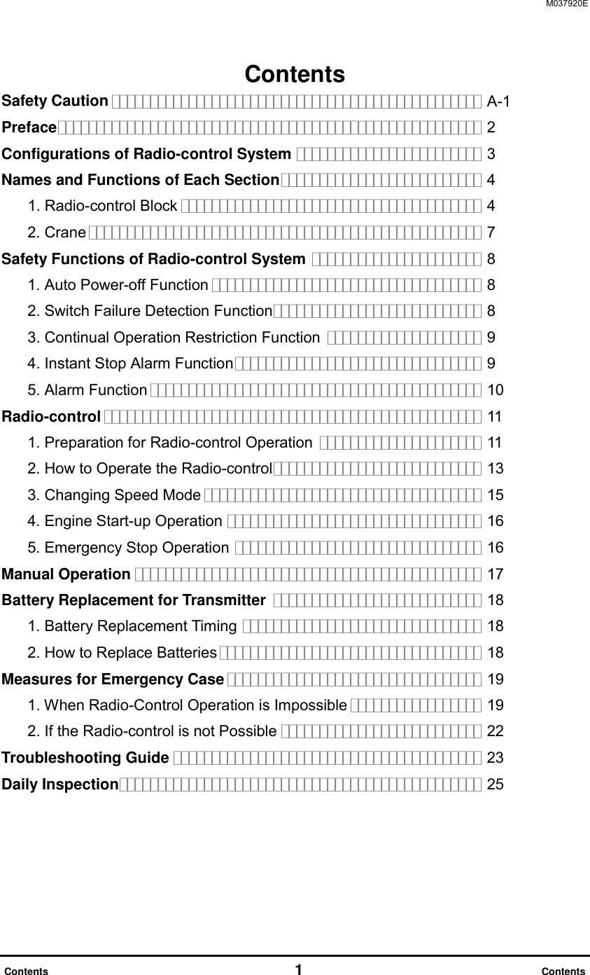
![M037990E Battery Replacement for Transmitter 18 Battery Replacement for Transmitter Battery Replacement for Transmitter 1. Battery Replacement Timing Replace the batteries in the following cases. (1) When the power LED of the transmitter flashes. (2) When the alarm (which has a “two-tone” sound) sounds while the motion selection switch is operated. The power LED also flashes in this case. 2. How to Replace Batteries [NOTE] Inserting the batteries incorrectly for plus (+) and minus (-) may cause a liquid spill, ignition, heat generation, and burst. Insert the batteries according to the direction plate. If the battery cover is loosely fixed, water may enter inside and cause a problem. Fasten the fixing screw securely. 1. Open the batteries cover and remove the old batteries. 2. After replacing the new batteries, close the battery cover and fasten the fixing screw. Use four AA-size batteries. Do not mix any old or different types. Two-tone AlarmPower LED (Flashing)Fixing screwBattery coverAA-size batteryDirection plate](https://usermanual.wiki/Tadano/RCSFT1-433/User-Guide-2225291-Page-19.png)