Tecom Co GW6000 Intelligent Gateway User Manual AH4021
Tecom Co Ltd Intelligent Gateway AH4021
Tecom Co >
Contents
- 1. User Manual 1 of 2
- 2. User Manual 2 of 2
User Manual 1 of 2
TECOM GW6000
Administrator’s Manual
(ver.1.2.x)
Copyright © 2006 by TECOM CO. LTD.

GW 6000 Administrative Guide Table of Contents
Table of Contents
1. Introduction......................................................................................................................5
2. Getting to Know the Router..............................................................................................7
2.1 Specifications...........................................................................................................................................................7
2.2 Front Panel............................................................................................................................................................... 7
2.3 Rear Panel................................................................................................................................................................ 8
3. System Features..............................................................................................................9
3.1 Answering Position ..................................................................................................................................................9
3.2 Auto Attendant & Voice Mail...................................................................................................................................9
3.3 Call Abandon .........................................................................................................................................................10
3.4 Call Operator (Call Attendant)............................................................................................................................... 10
3.5 Call Routing...........................................................................................................................................................10
3.6 Caller ID ................................................................................................................................................................10
3.7 Caller ID to Extension ...........................................................................................................................................10
3.8 Class Of Service (COS) ......................................................................................................................................... 10
3.9 Daylight Saving Time ............................................................................................................................................ 10
3.10 Default Set ........................................................................................................................................................... 10
3.11 Direct Inward System Access (DISA) via Auto Attendant................................................................................... 11
3.12 Dynamic DNS...................................................................................................................................................... 11
3.13 Extension Password ............................................................................................................................................. 11
3.14 Fax/Modem.......................................................................................................................................................... 11
3.15 Feature Key Programming................................................................................................................................... 11
3.16 Flash - Analog Port (SLT) Flash Recognition ...................................................................................................... 11
3.17 IG to IG................................................................................................................................................................ 11
3.18 IP Trunk ............................................................................................................................................................... 11
3.19 Line Group Assignment ....................................................................................................................................... 11
3.20 Make an Outside Call...........................................................................................................................................12
3.21 Message Waiting Indication.................................................................................................................................12
3.22 Multi-Line Appearance ........................................................................................................................................ 12
3.23 Music On Hold.....................................................................................................................................................12
3.24 Night Switching ................................................................................................................................................... 12
3.25 Numbering Plan ...................................................................................................................................................12
3.26 Paging .................................................................................................................................................................. 12
3.27 Plug and Play .......................................................................................................................................................12
3.28 Polarity Reversal (PR) Detection.........................................................................................................................12
3.29 PSTN Backup ......................................................................................................................................................13
3.30 Registration.......................................................................................................................................................... 13
3.31 Remote Management via PC................................................................................................................................13
3.32 System Time & Date............................................................................................................................................ 13
3.33 Toll Restriction.....................................................................................................................................................13
3.34 Transfer................................................................................................................................................................13
3.35 Trunk Group......................................................................................................................................................... 13
3.36 Wizard Setup........................................................................................................................................................ 13
4. Phone Features .............................................................................................................15
4.1 Alphanumeric Display ...........................................................................................................................................15
4.2 Basic Call...............................................................................................................................................................15
4.3 Call Forward via Auto Attendant ...........................................................................................................................15
4.4 Call Hold................................................................................................................................................................ 16
4.5 Call Transfer ..........................................................................................................................................................16
4.6 Call Waiting ...........................................................................................................................................................16
4.7 Conference.............................................................................................................................................................17
4.8 COS Following ...................................................................................................................................................... 17
4.9 Distinctive Ringing ................................................................................................................................................ 17
4.10 Do Not Disturb (DND) via Auto Attendant .........................................................................................................17
4.11 External Call Forward (ECF) via Auto Attendant................................................................................................17
4.12 Feature Key Programming................................................................................................................................... 17
4.13 Last Number Redial (LNR)..................................................................................................................................17
4.14 LCD & Interactive Buttons..................................................................................................................................17
Copy Right 2006 Tecom, Co. LTD. All rights reserved Page 2 of 107

GW 6000 Administrative Guide Table of Contents
4.15 Mute..................................................................................................................................................................... 18
4.16 On Hook Dialing.................................................................................................................................................. 18
4.17 Page Allow/Deny ................................................................................................................................................. 18
4.18 Phone Book.......................................................................................................................................................... 18
4.19 Phone Lock/Unlock .............................................................................................................................................18
4.20 Speed Dial............................................................................................................................................................18
4.21 Volume Control.................................................................................................................................................... 18
5. Quick Installation............................................................................................................19
5.1 Connecting the GW6000........................................................................................................................................19
5.2 Wizard Setup.......................................................................................................................................................... 19
5.2.1 WAN Setting ..................................................................................................................................................19
5.2.2 LAN Setting ...................................................................................................................................................22
5.2.3 Wireless Basic................................................................................................................................................23
5.2.4 Wireless Security............................................................................................................................................23
5.2.5 Internet Time..................................................................................................................................................24
5.2.6 Numbering Plan .............................................................................................................................................24
5.2.7 IP Trunk..........................................................................................................................................................25
5.2.8 Call Routing Table ......................................................................................................................................... 27
5.2.9 Wizard Setup Finished ...................................................................................................................................27
6. Configuration .................................................................................................................28
6.1 Setup ......................................................................................................................................................................28
6.2 Establish The Connection ......................................................................................................................................28
6.3 Device Info ............................................................................................................................................................ 31
6.3.1 Summary ........................................................................................................................................................31
6.3.2 Statistics ......................................................................................................................................................... 31
6.3.3 Route .............................................................................................................................................................. 31
6.3.4 ARP................................................................................................................................................................32
6.4 Advanced Setup .....................................................................................................................................................33
6.4.1 LAN ............................................................................................................................................................... 33
6.4.2 WAN...............................................................................................................................................................34
6.4.3 Route .............................................................................................................................................................. 36
6.4.4 NAT................................................................................................................................................................ 38
6.4.5 Security .......................................................................................................................................................... 41
6.4.6 Quality of Service ..........................................................................................................................................44
6.4.7 Dynamic DNS................................................................................................................................................47
6.5 Wireless.................................................................................................................................................................. 48
6.5.1 Basic............................................................................................................................................................... 48
6.5.2 Security .......................................................................................................................................................... 48
6.5.3 MAC Filter..................................................................................................................................................... 50
6.5.4 Wireless Bridge..............................................................................................................................................51
6.5.5 Advanced........................................................................................................................................................ 52
6.5.6 Station Info.....................................................................................................................................................54
6.6 Voice ......................................................................................................................................................................55
6.6.1 Phone.............................................................................................................................................................. 55
6.6.2 Trunk .............................................................................................................................................................. 57
6.6.3 Voice Mail ......................................................................................................................................................72
6.7 Management........................................................................................................................................................... 76
6.7.1 Settings........................................................................................................................................................... 76
6.7.2 Log ................................................................................................................................................................. 77
6.7.3 Internet Time..................................................................................................................................................78
6.7.4 Access Control ............................................................................................................................................... 82
6.7.5 Update Software............................................................................................................................................. 84
6.7.6 Save & Reboot ...............................................................................................................................................84
6.8 Diagnostics............................................................................................................................................................. 85
Appendix 1: Product Summary ..........................................................................................87
Appendix 2: Auto Attendant and Voicemail System ...........................................................91
Appendix 2.1 System Voice Prompts........................................................................................................................... 91
Appendix 2.1.1 Preset Voice Prompts.....................................................................................................................91
Appendix 2.1.2 Voice Prompts Recording .............................................................................................................. 93
Copy Right 2006 Tecom, Co. LTD. All rights reserved Page 3 of 107

GW 6000 Administrative Guide Table of Contents
Appendix 2.2 Flowchart...............................................................................................................................................94
Appendix 2.2.1 Automated Attendant.....................................................................................................................94
Appendix 2.2.2 Subscriber Voicemail Flowchart.................................................................................................... 96
Appendix 2.2.3 Mailbox Administer Flowchart......................................................................................................98
Appendix 2.2.4 System Administrator’s Voicemail Flowchart .............................................................................103
Appendix 3: Feature Access Codes Assignment .............................................................106
Copy Right 2006 Tecom, Co. LTD. All rights reserved Page 4 of 107
GW 6000 Administrative Guide Introduction
1. Introduction
Congratulate on becoming the owner of the GW6000.Your LAN (local area network) and
WAN (wide area network) will now be able to access the Internet using your high-speed
Ethernet connection. This Administrator Manual will show you how to install and set up
your GW6000.
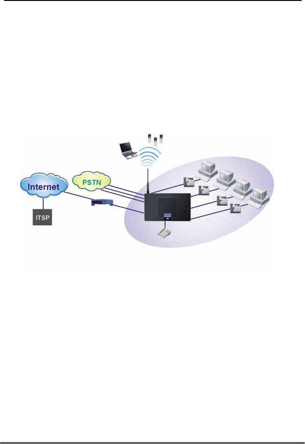
The IG (Intelligent Gateway) provides a variety of functions for users and can support a
wide range of application in a complicated environment. Therefore, it needs
Administrator to plan, install and set the whole environment of VoIP communication. And
the knowledge of modern network and Internet technologies are essential for
administrator.
A
nalog Phone
A
DSL Modem / Cable Modem
WiFi Phone
Notebook
PC
Figure 1-1. Router Connection Diagram
Interfaces
z WAN Interface: 10/100Base-T Ethernet port
z CO Interface: 3 FXO (Loop Start, for PSTN)
z Analog Device Interface: 1 FXS (for analog Telephone or FAX)
z LAN Interface: 4 Ethernet (10/100Base-T)
z Built-in 802.11g Wi-Fi access point
Terminals
z 1 Analog Terminal
z 24 IP Stations (Wired/Wi-Fi IP Phone)
In principle, the Administration is required to do the following things:
(1) To understand the architecture, resources, and devices of whole environment
which will be involved with the VoIP communications.
(2) To build a common setting file for most users.
Copy Right 2006 Tecom, Co. LTD. All rights reserved Page 5 of 107

GW 6000 Administrative Guide Introduction
(3) To configure each phone and install them into the network.
(4) To configure each interfaces and install them into IG.
(5) And to solve the problems what users encounter during operation.
Copy Right 2006 Tecom, Co. LTD. All rights reserved Page 6 of 107
This device complies with Part 15 of the FCC Rules. Operation is subject to the
following two conditions: (1) this device may not cause harmful interference, and
(2) this device must accept any interference received, including interference that may
cause undesired operation.
Notice : The changes or modifications not expressly approved by the party
responsible for compliance could void the user’s authority to operate the equipment.
IMPORTANT NOTE: To comply with the FCC RF exposure compliance requirements,
no change to the antenna or the device is permitted. Any change to the antenna or the
device could result in the device exceeding the RF exposure requirements and void
user’s authority to operate the device.The antenna used for this transmitter must be
installed to provide a separation distance of at least 20cm from all persons and must not
be co-located or operating in conjunction with any other antenna or transmitter.
FCC INFORMATION
The Federal Communication Commission Radio Frequency Interference
Statement includes the following paragraph:
The equipment has been tested and found to comply with the limits for a Class
B Digital Device, pursuant to part 15 of the FCC Rules. These limits are designed
to provide reasonable protection against harmful interference in a residential
installation. This equipment generates, uses and can radiate radio frequency
energy and, if not installed and used in accordance with the instruction, may cause
harmful interference to radio communication. However, there is no grantee that
interference will not occur in a particular installation. If this equipment dose cause
harmful interference to radio or television reception, which can be determined by
turning the equipment off and on , the user is encouraged to try to correct the
interference by one or more of the following measures:
--Reorient or relocate the receiving antenna.
--Increase the separation between the equipment and receiver.
--Connect the equipment into an outlet on a circuit different from that to which the
receiver is connected.
--Consult the dealer or an experienced radio/TV technician for help.
The user should not modify or change this equipment without written approval
form TECOM CO., LTD. Modification could void authority to use this equipment.

GW 6000 Administrative Guide Installation
2. Getting to Know the Router
2.1 Specifications
Feature Additional Info
Main Processor 240MHZ MIPS32 CPU
Processor SDRAM External 32MB
Processor Flash ROM External 4MB
Supplementary Processor 1x DSP Voice Pump VP101-4 (4 channel/each)
System Flash (Voice Mail) 128MB
Switch controller Broadcom BCM5325E
System Power: 15V/1A
Standards IEEE802.11g,IEEE802.11b,IEEE802.3
Ports 1×WAN,4×LAN,1×FXS ,3×FXO
Button Reset, Power on/off
Cabling RJ-45,RJ-11
LEDs POWER, WIRELESS, 3×LINE, TEL, 4×ETHERNET, WAN
EMI/EMC: FCC Part15 Class B
Operating Temp .0ºC to40ºC (32ºF to 104ºF)
Storage Temp. -20ºC to 70ºC (-4ºF to 158ºF)
Operating Humidity 10% to 80% relative humidity, Non-Condensing
Environmental
Storage Humidity 10% to 90% Non-Condensing
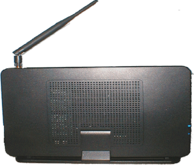
2.2 Front Panel
The front panel contains several LEDs that indicate the status of the unit.
Figure 2-1. Front Panel of GW6000
LED Name Color Status Description
On Power on. POWER Blue
Off Power off.
On Wireless LAN initialization success. WIRELESS Blue
Off Wireless LAN is not present.
Off PSTN Line is idle. LINE (1-3) Blue On PSTN Line is busy.
Off Phone is idle. TEL Blue
On Phone is busy.
On LAN connected.
Off LAN network connection not present.
ETHERNET(1-4) Blue
Flashing LAN activity present (traffic in either direction).
On WAN connected.
Off WAN network connection not present.
INTERNET Blue
Flashing WAN activity present (traffic in either direction).
Copy Right 2006 Tecom, Co. LTD. All rights reserved Page 7 of 107

GW 6000 Administrative Guide Installation
2.3 Rear Panel
The rear panel contains the ports for the unit's data and power connections.
Figure 2-2. Rear Panel of GW6000
Label Function
WAN RJ-45 connector: Connects the device to your cable modem, or to your
ADSL Modem, It’s to connect to the remote network
LAN1-4 RJ-45 connector: Connects the device to your PC's Ethernet port, or to
the uplink port on your LAN's hub,
TEL1 RJ-11 connector: Connects the device to your analog phone,
Line 1-3 RJ-11 connector: Connects the device to your PSTN lines
Power Connects to the supplied power converter cable
On/Off Switches the device on and off
Copy Right 2006 Tecom, Co. LTD. All rights reserved Page 8 of 107

GW 6000 Administrative Guide System Features
3. System Features
3.1 Answering Position
For incoming calls from PSTN (FXO ports), system provides the flexibility to ring to
different destinations. System also provides the ability to have the calls to ring to 1-6
different extensions according to the system service mode (day or night modes).
It is also for those incoming VoIP calls from the registered ISP (Uplink Server) to be
routed with the same method.
3.2 Auto Attendant & Voice Mail
The IG Auto Attendant can greatly enhance business office productivity by providing
either a full-duty automated attendant to handle all incoming system calls or part-duty
automated attendant to handle overflow traffic.
The Automated Attendant & Voice Mail Module provides 128MB of programmable voice
announcements. It provides four ports to handle four (4) simultaneous callers. It
provides the following functions:
z Auto Attendant Functions
It provides an incoming caller with a customized welcome greeting that
describes the actions available to an incoming caller:
Provide four kinds of main greeting messages: Day, Night, Noon,
and Holiday greeting messages.
Dial an extension number or operator code to reach the appreciate
destination.
Press a digit to leave a message in a particular mailbox.
Press a digit to make an outside call via the specified check.
Provide the phone to forward the call to its voicemail box.
Provide the phone to set Direct Call Forward, Busy Call Forward or
No Answer Call Forward. It will forward the incoming trunk call to
another extension.
Provide the phone to set Do Not Disturb to stop the incoming line call
from ringing.
z Voice Mail Functions
All mailbox users have access to these mailbox features
Delete, save, or skip messages.
Send messages to other mailbox.
Receive message information indicating the date, time, and sender
information, if available.
Change personal greeting, and password.
Playback controls when reviewing messages.
Record a temporary greeting.
Send a notification via email when getting a leaving message.
The maximum recording length for each call is 60 seconds.
The maximum total length for each user is about 18 minutes.
For each leaving message, it's saved 1 - 7 days
z Voice Messages
Provide two languages service for the all voice files.
Administrators can record the all voice messages by themselves.
Copy Right 2005 Tecom, Co. LTD. All rights reserved Page 9 of 107

GW 6000 Administrative Guide System Features
Administrators can update, backup or delete the all voice messages
on the PC.
3.3 Call Abandon
For every PSTN call, system provides the facility to monitor the call status. If the remote
party hangs up, the ongoing call must be terminated.
3.4 Call Operator (Call Attendant)
One primary operator may be assigned in the system. The standard IP phone will serve
as the operator telephone. When assigned as operator, this extension supports general
system functions.
While the internal extension dials Operator Directory Number ("0" at default), or the
outside party dials "0" when Auto Attendant plays the Welcome message, these calls
will be stored into Operator Queue. The Operator is First-In-First-Out to service these
calls. At the waiting time, the calling party will be on Music-On-Hold state.
3.5 Call Routing
The Call Routing feature automatically routes outgoing calls using the most appropriate
route. The appropriate route is determined based on the number dialed. If necessary,
GW6000 can automatically modify the dialed number by deleting and inserting digits.
The call routing destination is a PSTN line, an IP line, a line group or another GW6000.
3.6 Caller ID
GW6000 provides the ability to detect the calling party identification provided by CO via
PSTN lines or by Uplink Server via IP trunks. This data when received by the telephone
carrier will be displayed on all ringing IP phones or Caller ID equipped Single Line
Telephone.
3.7 Caller ID to Extension
When Caller ID data is received on PSTN Lines or IP Lines of the IG system, this caller
ID data is re-broadcast to analog devices or IP phones. This means that Caller ID will be
supported even when connected “behind” the IG system as a system extension.
3.8 Class Of Service (COS)
GW6000 provides eight (8) Classes of Service (COS) for assignment of outside line
dialing-privileges. Each extension may be assigned one Day-COS and one Night-COS.
The Extension COS is primarily used for restriction and control of long distance dialing.
COS 0 is the highest priority. COS 7 is the lowest one.
3.9 Daylight Saving Time
Daylight Saving Time (DST) feature supports auto adjustment for daylight saving time.
3.10 Default Set
When the feature is active, the extension will return to default settings. It will affect the
following options:
Cancel any Call Forward via AA
Cancel DND via AA
Paging Accept
Copy Right 2006 Tecom, Co. LTD. All rights reserved Page 10 of 107

GW 6000 Administrative Guide System Features
Default Feature Key Setting
3.11 Direct Inward System Access (DISA) via Auto Attendant
The current PSTN/IP lines are all DISA lines. While ringing to AA, the outside callers
have direct access to extensions, PSTN/IP lines, Call Routing and Trunk Groups.
3.12 Dynamic DNS
GW6000 support Dynamic DNS to see the DDNS host name as GW6000’s WAN IP
address in SIP application. Let the GW6000 have a static domain name for dynamic IP
address.
Before using the feature, you must register domains on DynDNS.org or TZO.
3.13 Extension Password
All extensions of the IG system have an associated User Password. Password length is
system programmable from 0 to 24 characters.
3.14 Fax/Modem
GW6000 supports FAX/modem tone detection and auto-fallback to G.711.
3.15 Feature Key Programming
Feature Keys can be programmed by phone users. A feature key can be programmed
for line appearance.
3.16 Flash - Analog Port (SLT) Flash Recognition
Flash is the momentary operation of the hook-switch at the analog device, which can be
deciphered by the IG system in such a way that the previous call in progress is held, or
placed in a status of transfer awaiting further instructions from the user.
3.17 IG to IG
While dialing a number, it may route to another GW6000 through Call Routing Table. It
allows the user to make a direct call to an extension in another GW6000. It also allows
the user to share the PSTN or IP Trunks in another GW6000 to make an outside call.
3.18 IP Trunk
GW6000 can register up to 8 SIP Uplink Servers. The extensions may make a call to the
users of the Uplink Servers, or any user in the world through the Uplink Servers.
z SIP message, including INVITE, re-INVITE, ACK, CANCEL, OPTIONS, BYE,
REGISTER, INFO, REFER, SUSCRIBE/NOTIFY and REPLACE messages.
z SIP Outbound Proxy, SIP Proxy and Registrar
z Auto-Registration when power-on or period
z Session Timer support
z Support IP address, domain name, user name, display name for SIP URL
3.19 Line Group Assignment
System assigns each PSTN/IP line to a specific Line Group. Each line can be assigned
to only one Line Group. The Line group assignment is used for Line pool access.
If setting some PSTN lines and some IP lines into the same Line Group, the line access
depends on the access priority.
Copy Right 2006 Tecom, Co. LTD. All rights reserved Page 11 of 107

GW 6000 Administrative Guide System Features
3.20 Make an Outside Call
System provides three methods to make an outside call.
z The extension user dials the phone number directly. System automatically
routes the outgoing call using the least expensive line via Call Routing Table.
z The extension user dials a Line number or a Line Group number first. After
hearing the dial tone, the user dials the phone number.
z The extension presses a Line key first. After hearing the dial tone, the user
dials the phone number.
3.21 Message Waiting Indication
It’s a Voice Mail feature. When somebody leave messages, the router will inform the
phones, and phones’ LCD will display new voice mails information, and its led will flash
accordingly.
3.22 Multi-Line Appearance
GW6000 provides PSTN line and IP line status to the phones.
Trunk LED:
Dark – the line is Null or Idle
Lit – the line is in Talk
3.23 Music On Hold
Any PSTN/IP line calls which placed on hold will give music to the other external party.
3.24 Night Switching
GW6000 provide Day and night settings in service mode page. And during different time,
Trunk incoming call will be forwarded to different extensions according to the settings.
3.25 Numbering Plan
The Numbering Plan refers to the structure of dialed access to the various resources
that are part of the system. GW6000 also allows for a very flexible configuration
numbering for the various system resources.
3.26 Paging
A Page can be initiated from any extension in the system. Dialing a Paging Group
Directory number allows an extension to broadcast a page to all assigned members of
the selected paging group.
3.27 Plug and Play
While connecting IP2007/2008 phones to GW6000 LAN port, it will register to GW6000
automatically.
3.28 Polarity Reversal (PR) Detection
When making an outgoing PSTN call, the system must know if the remote party answers
the call or not (for SMDR recording purpose). If the CO provides the PR signal, the
system can monitor the signal to determine whether the remote party answers the call or
not.
Copy Right 2006 Tecom, Co. LTD. All rights reserved Page 12 of 107

GW 6000 Administrative Guide System Features
3.29 PSTN Backup
In case of power failure, GW6000 automatically switches the first PSTN line to the
Single-line analog phone. The other PSTN lines are not supported.
3.30 Registration
The IG combines Proxy and Registrar servers in its application. For a Registrar server, it
acts as the front end to the location service for a domain, reading and writing mappings
based on the contents of REGISTER requests. The location service is then typically
consulted by a Proxy server.
3.31 Remote Management via PC
Programming the IG system database is possible via PC. IG build-in a web server for
remote administration.
3.32 System Time & Date
The IG system provides a built-in time clock to track System Time for reference in
certain features such as System Night Service Mode Change. This clock has the ability
to automatically adjust with network NTP server through Internet.
3.33 Toll Restriction
GW6000 provides sophisticated monitoring of digits dialed on PSTN/IP Trunks. If a digit
or range of digits dialed on a Trunk line is inconsistent with the dialing extension’s COS,
the call is denied. This calling COS criteria can be applied to local calls, long distance
calls, and specific numbers that are considered allowed in areas where other numbers
may be restricted.
3.34 Transfer
Transfer is used to deliver calls at your extension to another extension. It means that
calls can be routed to IG system destinations: an extension or an outside phone number.
3.35 Trunk Group
System assigns each PSTN Trunk and IP Trunk to a specific Trunk Group. Each Trunk
can be assigned to only one Trunk Group. The Trunk group assignment is used for
Trunk pool access.
If setting some PSTN trunks and some IP trunks into the same Trunk Group, the trunk
access depends on the access priority.
System provides up to 4 Trunk Groups. All PSTN Trunks and IP Trunks are assigned to
default Trunk Group 1 and PSTN Trunks has higher access priority.
3.36 Wizard Setup
Wizard Setup allows system administrator to select the appropriate mode and configure
the corresponding settings step by step to create a basic GW6000 operation.
The following eight operation setting items are supported
WAN Setting
LAN Setting
Wireless Basic
Copy Right 2006 Tecom, Co. LTD. All rights reserved Page 13 of 107

GW 6000 Administrative Guide System Features
Wireless Security
Internet Time
Numbering Plan
IP Trunk
Call Routing Table
.
Copy Right 2006 Tecom, Co. LTD. All rights reserved Page 14 of 107

GW 6000 Administrative Guide Quick Installation
4. Phone Features
The following features depend on whether the phone provides.
Feature Tecom
IP 2007/8
FXS Other
SIP Phones
Alphanumeric Display Yes Depends Depends
Basic Call Yes Yes Yes
Call Forward via Auto Attendant Yes Yes No
Call Hold Yes Yes Yes
Call Transfer Yes Yes Depends
Call Waiting Yes No Depends
Conference Yes No Depends
COS Following Yes No No
Distinctive Ringing Yes No No
Do Not Disturb via Auto Attendant Yes Yes No
External Call Forward (ECF) via Auto
Attendant Yes Yes Yes
Feature Key Programming Yes No No
Last Number Redial Yes Yes Depends
LCD & Interactive Buttons Yes No Depends
Mute Yes No Depends
On Hook Dialing Yes No Depends
Page Allow / Deny Yes No No
Phone Book Yes No Depends
Phone Lock/Unlock Yes No No
Speed Dial Yes No Depends
Volume Control Yes Depends Depends
Tips: the word “Depends” means that the features depend on whether the phone
provides.
4.1 Alphanumeric Display
The IP Phone extension provides a graphic LCD that supports 64 alphanumeric
characters. The LCD enhances many system features.
4.2 Basic Call
To make an intercom call, dial a Station number (IP Terminal, POTS) or a Voice Mail
number.
To make an outgoing call, dial a phone number. System chooses a line (PSTN line or IP
trunk) via Call Routing Table to dial out. If it includes “*” in the phone number, and the
call is dialed through PSTN Trunk, it will be as a one second Pause time.
To make an outgoing call, dial a PSTN, an IP Trunk or a Trunk Group number first. After
hearing dial tone, dial the phone number.
4.3 Call Forward via Auto Attendant
Auto Attendant Call Forwarding reroutes incoming trunks calls from one extension to
another destination. The destination of a call forward can be another extension or an
outside phone number (External Call Forward; ECF).
GW6000 support the following Call Forwards:
Copy Right 2006 Tecom, Co. LTD. All rights reserved Page 15 of 107

GW 6000 Administrative Guide Quick Installation
Direct Call Forward:
Forward all of the calls without regard to the extension status.
To enable, dial *21 + Ext No.
*21 + * + (PSWD) + * + Destination
To disable, dial **21.
Busy Call Forward
Forwards the calls if the extension is busy.
To enable, dial *22 + Ext No
*22 + * + (PSWD) + * + Destination
To disable, dial **22.
No Answer Call Forward
Forward the calls if the extension doesn’t answer the call within No
Answer Time.
To enable, dial *23 + Ext No + * + Time.
*23 + * + (PSWD) + * + Destination + * + Time.
To disable, dial **23.
Direct Call Forward to VM
Forward all of the calls to its own Voice Mail box.
To enable, dial *24.
To disable, dial **24.
4.4 Call Hold
Trunk and Intercom calls can be placed on hold at any extension. Callers on hold hear
the Music On Hold.
For the Single Line phone, it’s to put a call on hold, press flash then hang up (optional).
It’s to return to the original call, press flash or pick up the phone.
For Tecom IP2007/2008, please refer to “IP Phone User Guide”.
4.5 Call Transfer
It allows a user to perform a screened or unscreened transfer to an extension or an
outside phone number.
For the Single Line phone, it’s to transfer a call, press flash then dial the new number.
To transfer immediately, hang up (Unscreened). To transfer with consultation, wait for
the party to answer, consult, and then hang up (Screened). To abort the transfer (if the
third party does not answer), press flash to return to the original call.
For Tecom IP2007/2008, please refer to “IP Phone User Guide”.
4.6 Call Waiting
If call waiting is disabled on a line, it returns busy response while getting second call at
non-idle state.
To enable the call waiting feature, dial *99.
To disable the call waiting feature, dial **99.
Copy Right 2006 Tecom, Co. LTD. All rights reserved Page 16 of 107

GW 6000 Administrative Guide Quick Installation
4.7 Conference
The Conference feature allows the user to connect to two or more parties into a single
conversation.
For Tecom IP2007/2008, please refer to “IP Phone User Guide”.
4.8 COS Following
You can change the individual Class of Service of each extension temporarily. You may
want to do this when the user goes to the office of low-priority COS extension and try to
make an outgoing call, the user can use the function to use his/her own COS.
When setting COS following, the effective time of following is 1 minute.
To make a COS Following, dial *55+(phone number)+(password)
4.9 Distinctive Ringing
Distinctive ring cadences can be selected allowing adjacent users to discern which
extension is ringing. It also provides the different ring tones for intercom and trunk calls.
4.10 Do Not Disturb (DND) via Auto Attendant
Extension users can enable DND to stop incoming PSTN or IP Trunk calls from ringing
at their phone. The DND on an extension can be allowed or denied through the feature
access code.
If an extension has DND and Call Forward enabled at the same time, Calls follow the
DND.
To enable the do not disturb feature, dial *4.
To disable the do not disturb feature, dial **4.
4.11 External Call Forward (ECF) via Auto Attendant
Auto Attendant Call Forwarding reroutes incoming trunks calls from one extension to
another destination. The destination of a call forward can be an outside phone number.
4.12 Feature Key Programming
Feature Keys can be programmed by phone users. A feature key can be programmed
for line appearance, or a function such as Call Forward, Do Not Disturb.
It’s also allowed to program the Feature Keys by dialing feature Access Code:
*70 + (Feature Key number; 1 - 4) + (PSTN, IP Trunk or Trunk Group
number)
4.13 Last Number Redial (LNR)
The features depend on whether the phone provides.
The Last Number Redial feature automatically dials the last number dialed from the
phone. For the Single Line phone, it’s to dial *8. For Tecom IP2007/2008, please refer to
“IP Phone User Guide”.
4.14 LCD & Interactive Buttons
The IP phone is equipped with Liquid Crystal Display to enhance features operation.
And incorporates four-screen-prompt and interactive buttons that simplify feature
operation.
Copy Right 2006 Tecom, Co. LTD. All rights reserved Page 17 of 107

GW 6000 Administrative Guide Quick Installation
4.15 Mute
The Mute feature allows the user to disable the handset transmitter or the speakerphone
microphone.
For Tecom IP2007/2008, please refer to “IP Phone User Guide”.
4.16 On Hook Dialing
IP phone extensions may make outgoing calls without lifting the handset and monitor the
dialing status through the built-in speaker. The button lamp is lit when monitoring a call.
4.17 Page Allow/Deny
You can block one-way pages (internal, group, and all page) over the IP phone speaker
by dialing the Page Deny code.
To enable Page Deny feature, dial *99.
To disable Page Deny feature, dial **99.
4.18 Phone Book
In Phone book, each entry is containing of Phone Number and User Name. The phone
number could be extension number, phone number or IP address.
For Tecom IP2007/2008, please refer to “IP Phone User Guide”.
4.19 Phone Lock/Unlock
You can use the Lock feature to prevent unauthorized trunk calls from being made from
extension. A locked extension continues to receive incoming trunk calls, and a user can
continue to place and receive intercom calls. Outgoing Trunk calls are blocked.
To lock the phone, dial *97 + (password)
To unlock the phone, dial **97 + (password)
4.20 Speed Dial
Speed Dialing allows you to store frequently dialed numbers.
For Tecom IP2007/2008, please refer to “IP Phone User Guide”.
4.21 Volume Control
The IP phone is equipped with a volume control that is used to adjust the various
volume settings of the telephone. The following functions can be adjusted:
z Ringing
z Handset
z Speaker
z Headset
For Tecom IP2007/2008, please refer to “IP Phone User Guide”.
Copy Right 2006 Tecom, Co. LTD. All rights reserved Page 18 of 107

GW 6000 Administrative Guide Quick Installation
5. Quick Installation
This Quick Installation help to you install the product quickly and easily. For detailed
instructions on installation, and further setup option, please refer to the configuration
chapter.
5.1 Connecting the GW6000
(1) Place GW6000 in an optimum location.
(2) Connect the included Category 5 Ethernet network cable to the GW6000’s LAN port
or WAN port. Then connect the other end of the network cable to a switch or hub or
directly your PC’s Ethernet port. The GW6000 will then be connected to your 10/100
network.
(3) Connect the AC power adapter to the GW6000’s Power port. Only use the power
adapter supplied with the GW6000. Use of a different adapter may result in product
damage.
(4) Press the reset button on the rear panel to set the GW6000 to factory default settings.
(5) Now that you have connected the GW6000 to your network, you are ready to begin
setting it up. The Setup Wizard will take you through all necessary steps to help you to
configure the GW6000 easily.
5.2 Wizard Setup
This system administrator can configure the GW6000 remotely or locally via a Web
Browser. When GW6000 return to default factory settings, its LAN address is
“192.168.1.1” , and username is “admin”, password is “admin”.
Wizard Setup allows system administrator to select the appropriate operation mode and
configure the corresponding setting step by step. The following eight items are
supported.
z WAN Settings
z LAN Settings
z Wireless Basic
z Wireless Security
z Internet Time
z Numbering Plan
z IP Trunk
z Call Routing Table
In the configuration, the administrator presses “Next” or “Back” button to choose the
setting item. If pressing “Exit & Reboot”, it will asks whether store settings. If choose Yes,
the settings will be saved and the GW6000 will be reboot automatically. From now on, if
entering the GW6000 Web configuration, it goes to home page “Intelligent Gateway”
directly.
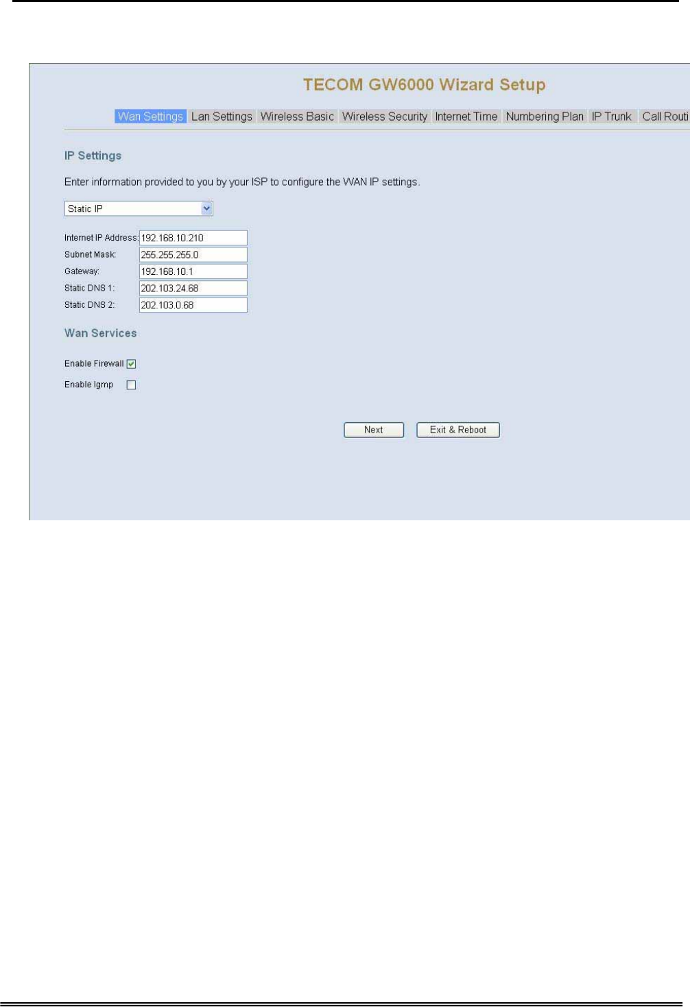
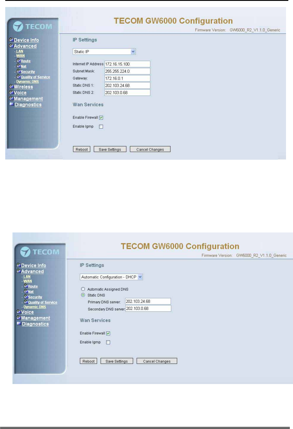
5.2.1 WAN Setting
There are three modes that you can configure WAN IP address: Static IP mode, DHCP
mode and PPPoE mode. You can also select to enable or disable Firewall and IGMP.
Note that Network Address Translation function (NAT) is default enabled and is not
showing on the page to prevent it from being disabled.
Copy Right 2006 Tecom, Co. LTD. All rights reserved Page 19 of 107
GW 6000 Administrative Guide Quick Installation
This page shows that the current existing WAN interfaces in the system is Static IP
mode. (Figure 5-1-1).
Figure 5-1-1. Wan Settings (Static IP mode)
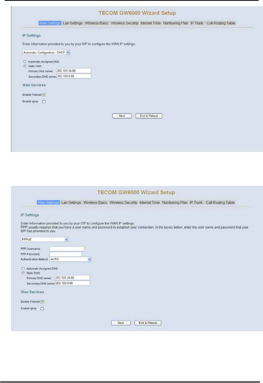
The Dynamic Host Configuration Protocol (DHCP) is an Internet protocol for automating
the configuration of computers that use TCP/IP. DHCP can be used to automatically
assign IP addresses, to deliver TCP/IP stack configuration parameters such as the
subnet mask and default router, and to provide other configuration information.
This page shows the current existing WAN interfaces in the system by DHCP mode
(Figure 5-1-2).
Copy Right 2006 Tecom, Co. LTD. All rights reserved Page 20 of 107
GW 6000 Administrative Guide Quick Installation
Figure 5-1-2. Wan Settings (DHCP mode)
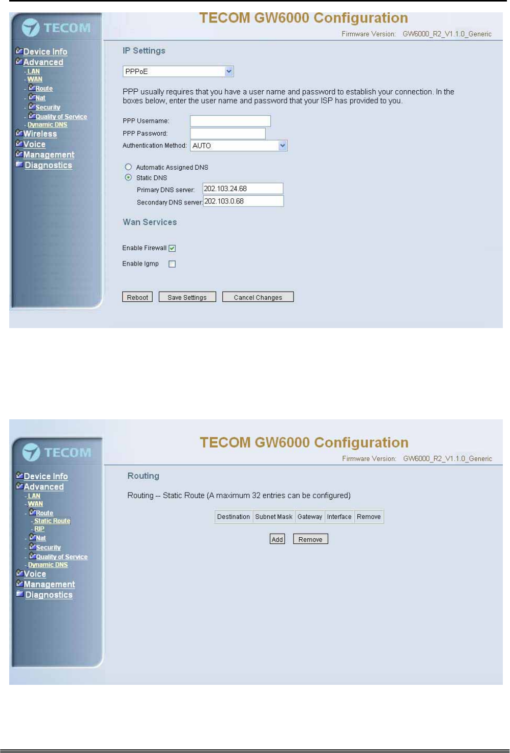
The Point-to-Point Protocol over Ethernet (PPPoE) requires a user name and password
that your ISP has provided to you to establish your connection. This page shows that the
current existing WAN interfaces in the system is PPPoE mode (Figure 5-1-3).
Figure 5-1-3. Wan Settings (PPPoE mode)
Copy Right 2006 Tecom, Co. LTD. All rights reserved Page 21 of 107
GW 6000 Administrative Guide Quick Installation
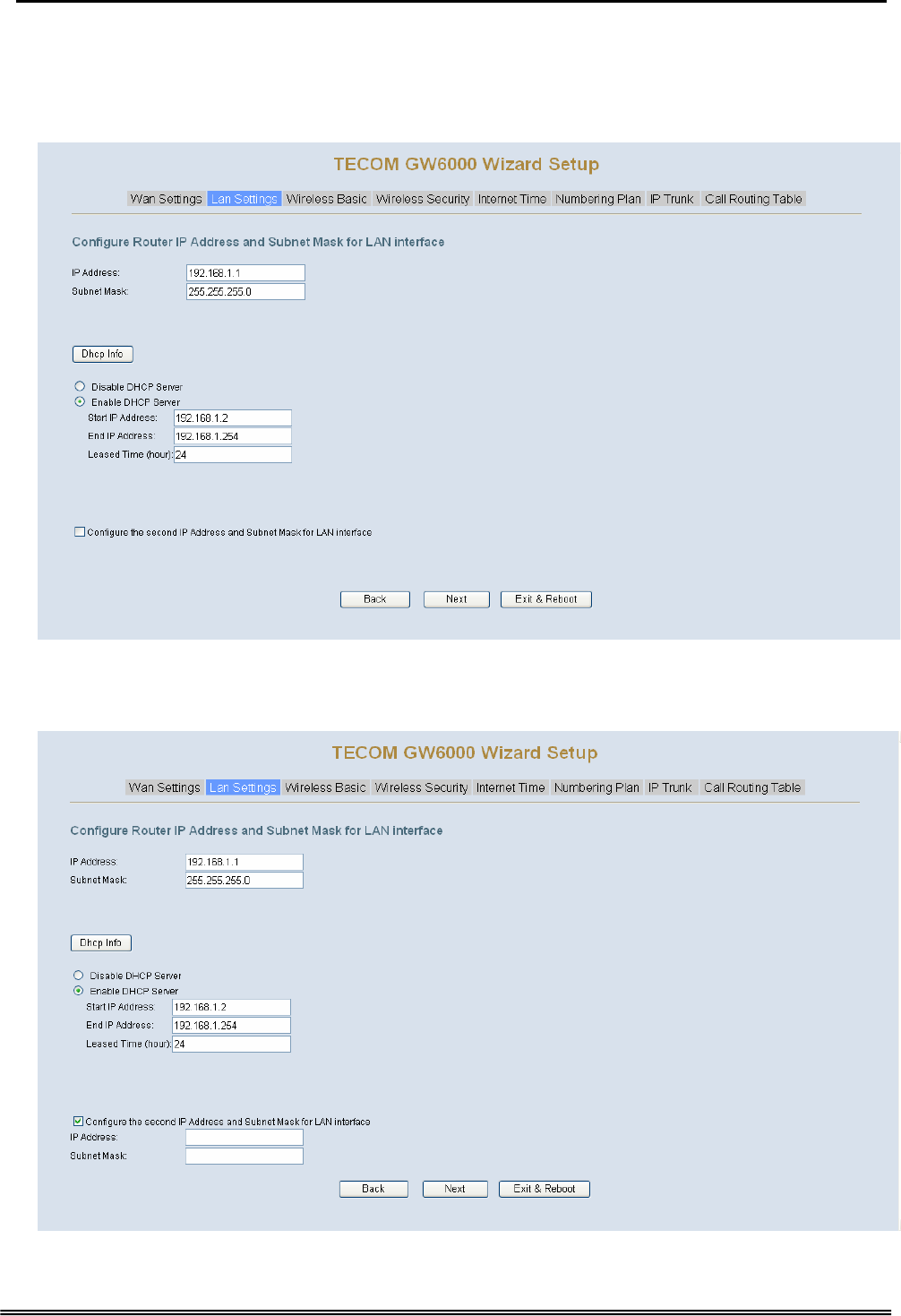
5.2.2 LAN Setting
It allows you giving LAN IP and Subnet Mask for LAN interface (Figure 5-2-1). You can
also select to enable or disable DHCP Server and configure related settings for that
mode.
Figure 5-2-1. Lan Settings
If necessary, check the “Secondary IP” to configure the secondary IP address and
Subnet Mask for LAN (Figure 5-2-2). This IP address is used for management only.
Figure 5-2-2. Lan Settings (Secondary LAN IP checked)
Copy Right 2006 Tecom, Co. LTD. All rights reserved Page 22 of 107
GW 6000 Administrative Guide Quick Installation
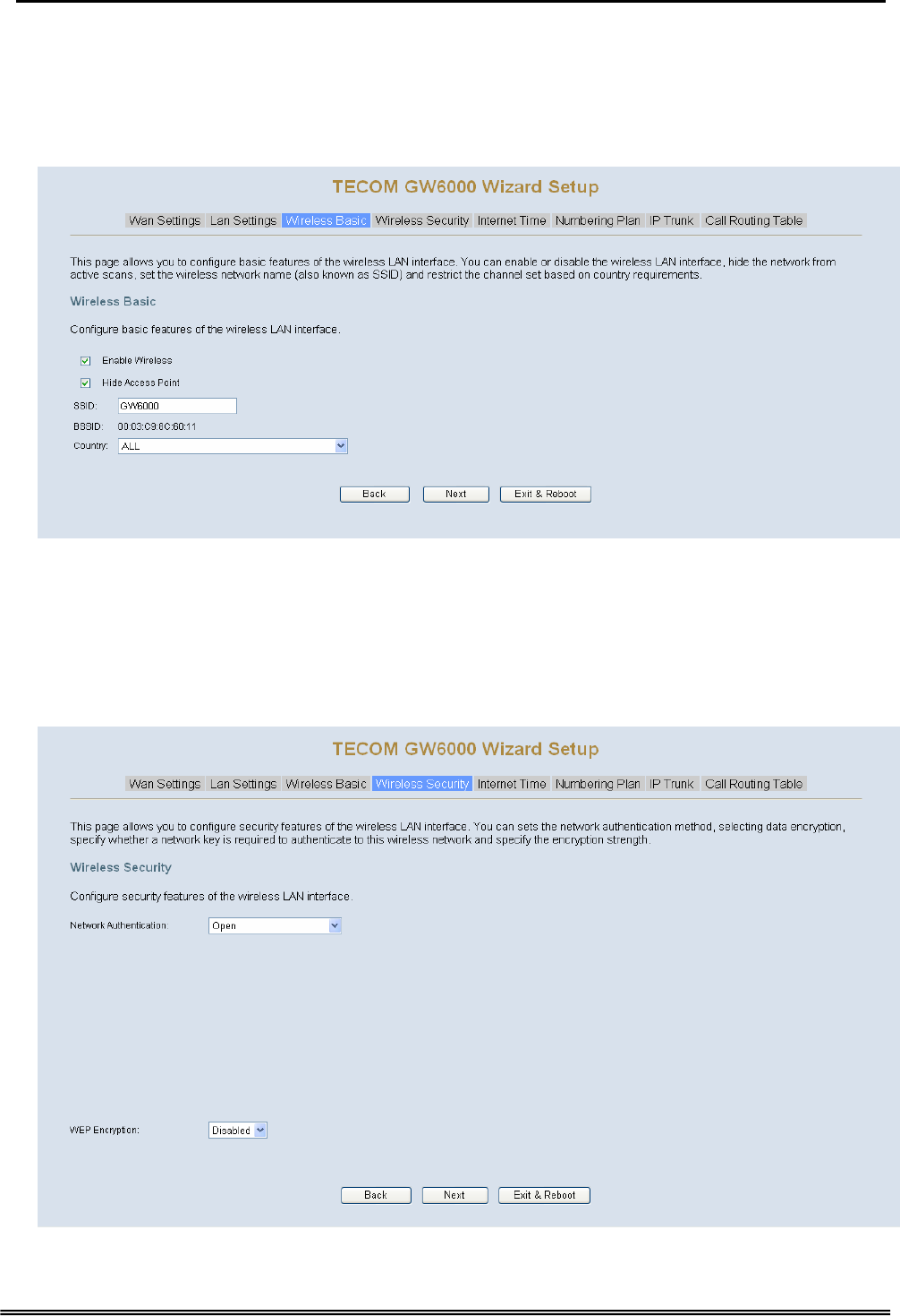
5.2.3 Wireless Basic
The page (Figure 5-3) allows you to configure basic feature of the wireless LAN
interface. You can enable or disable the wireless LAN interface, hide the network from
active scans, set the wireless network name (also known as SSID) and restrict the
channel set based on country requirement.
Figure 5-3. Wireless Basic
5.2.4 Wireless Security
The page (Figure 5-4) allows you to configure security features of the wireless LAN
interface. You can set the network authorization method, select data encryption, specify
whether a network key is required to authenticate to this wireless network and specify
the encryption strength.
Figure 5-4. Wireless Security
Copy Right 2006 Tecom, Co. LTD. All rights reserved Page 23 of 107
GW 6000 Administrative Guide Quick Installation
The item will be clearly described in 6.5.2.
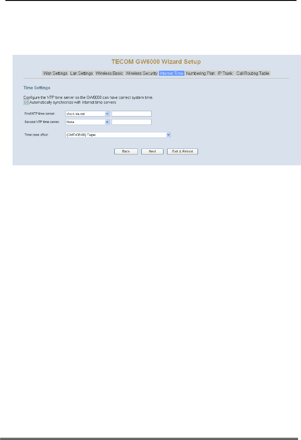
5.2.5 Internet Time
The page allows you to configure the NTP time server so the GW6000 can have correct
system time. It is useful such as reviewing the System Log.
Figure 5-5. Internet Time
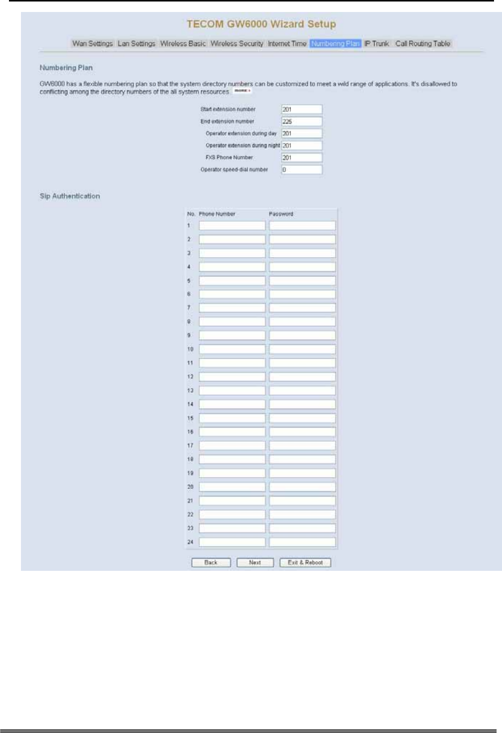
5.2.6 Numbering Plan
GW6000 has a flexible numbering plan so that phone or trunk numbers can be
customized to meet a wild range of applications. It will check the numbers what you
enter to prevent from conflicting among the all system resources.
Copy Right 2006 Tecom, Co. LTD. All rights reserved Page 24 of 107
GW 6000 Administrative Guide Quick Installation
Figure 5-6. Numbering Plan
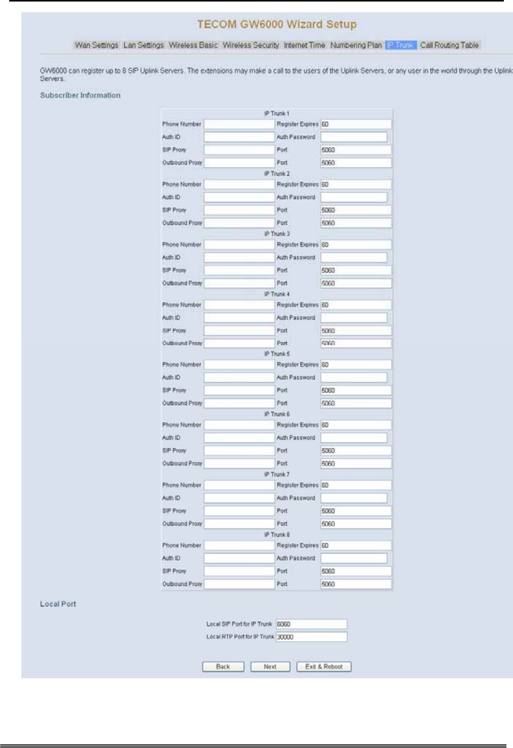
5.2.7 IP Trunk
GW6000 can register up to 8 SIP Uplink Servers. The extensions may make a call to the
users of the Uplink Servers, or any user in the world through the Uplink Servers.
Copy Right 2006 Tecom, Co. LTD. All rights reserved Page 25 of 107
GW 6000 Administrative Guide Quick Installation
Figure 5-7. IP Trunk
Copy Right 2006 Tecom, Co. LTD. All rights reserved Page 26 of 107
GW 6000 Administrative Guide Quick Installation
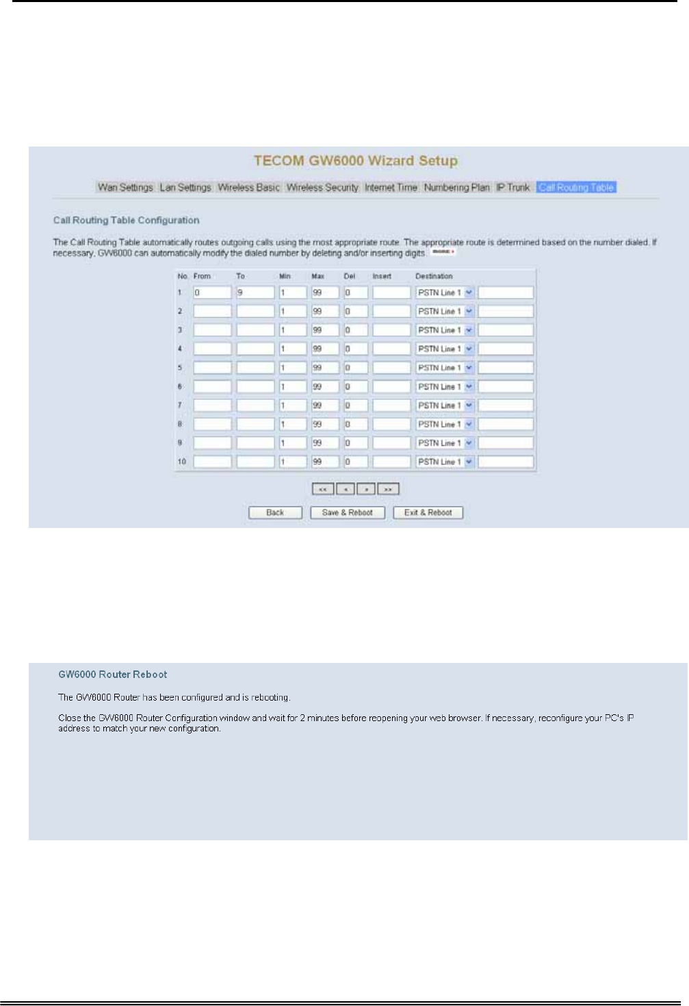
5.2.8 Call Routing Table
The Call Routing Table automatically routes outgoing calls using the most appropriate
route. The appropriate route is determined based on the number dialed. If necessary,
GW6000 can automatically modify the dialed number by deleting and/or inserting digits.
Figure 5-8. Call Routing Table
5.2.9 Wizard Setup Finished
When you click “Save & Reboot” Button at above page, the wizard setup will save your
setting and the wizard setup will finished. Then the system will reboot as shown below.
Figure 5-9. Wizard Setup finished
Congratulations! The installation of the GW6000 is complete.
For additional details, advanced configuration, or any other questions, refers to
the next chapter.
Copy Right 2006 Tecom, Co. LTD. All rights reserved Page 27 of 107
GW 6000 Administrative Guide Configuration
6. Configuration
6.1 Setup
z Connect the GW6000 and PC.
z The default LAN IP of the GW6000 is 192.168.1.1.
z The default WAN IP of the GW6000 is 192.168.10.210.
z For web login, the default user name is “admin”, the default password is “admin”.
z For telnet login, the default user name is “admin”, the default password is
“admin” in LAN port. But in WAN port, the default user name is “support”, the
default password is “support”.
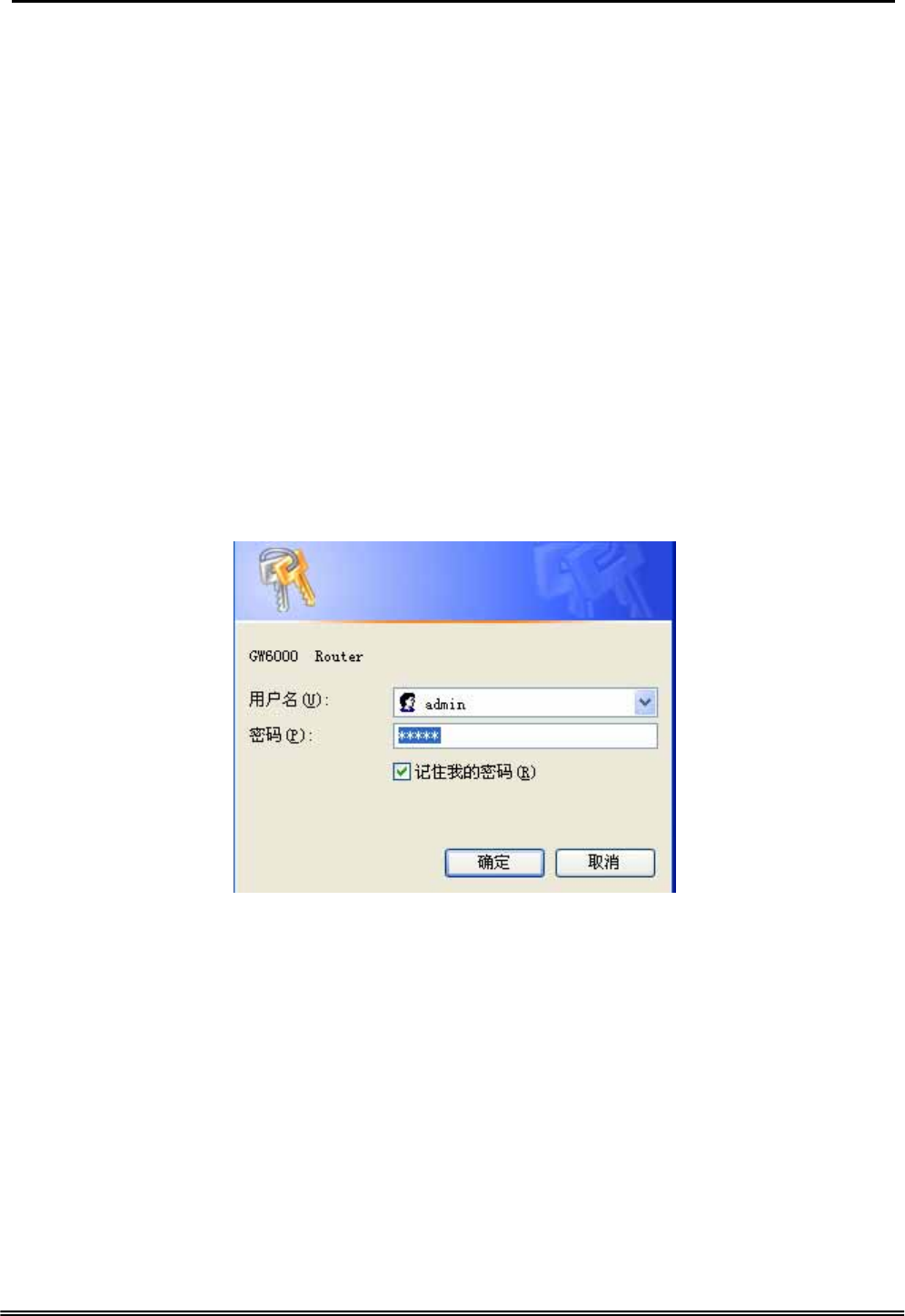
6.2 Establish The Connection
Enter the IP address of GW6000 from the Web Browser.
A Dialogue Box will pop up to request the user to enter username and password. (Figure
6-1)
Figure 6-1. Authentication
Please enter the management username/password into the fields then click the OK
button (default username/password is admin/admin).
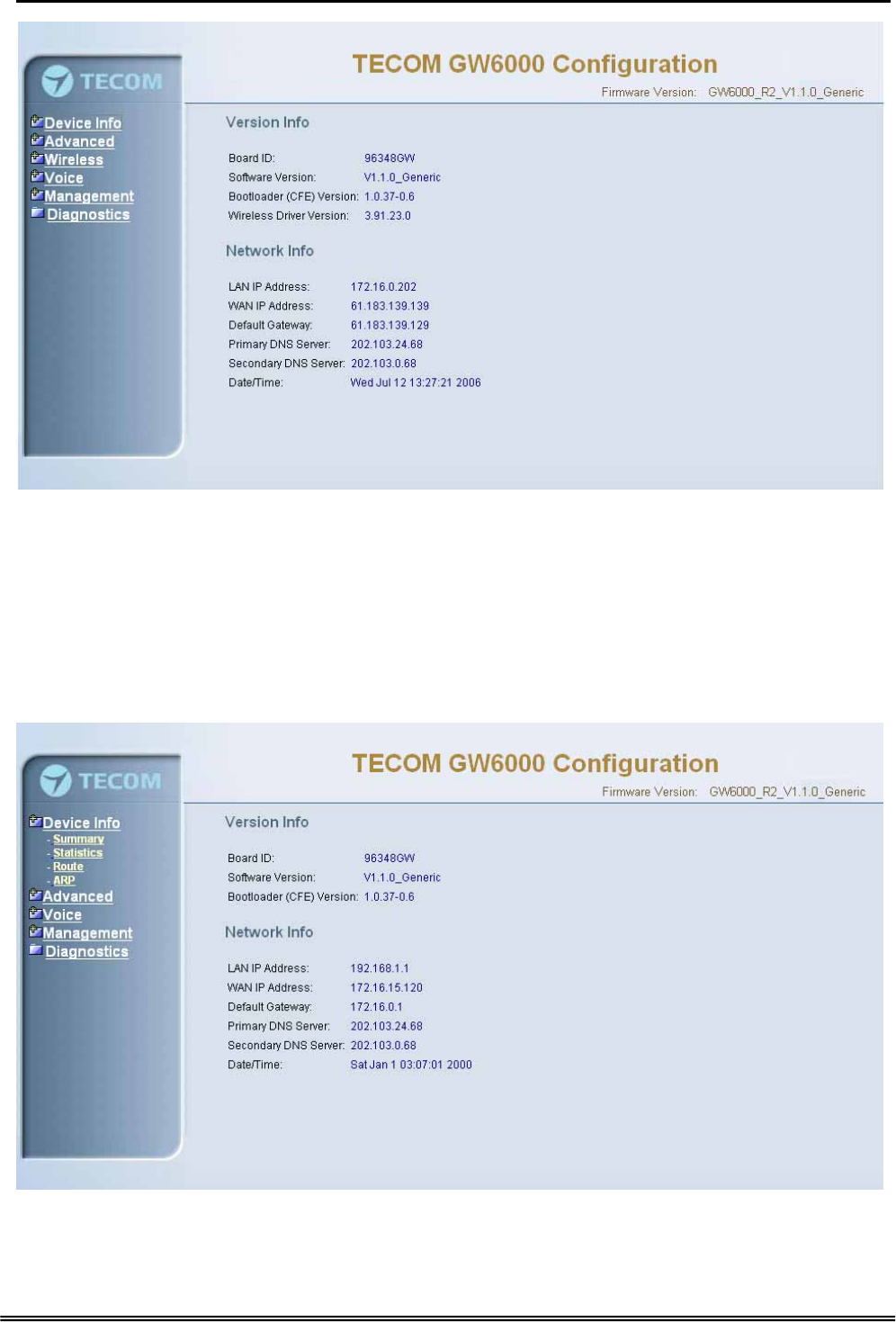
When the authentication is OK, the home page “Intelligent Gateway” will be displayed on
the browser (Figure 6-2).
Copy Right 2006 Tecom, Co. LTD. All rights reserved Page 28 of 107

GW 6000 Administrative Guide Configuration
Figure 6-2. Intelligent Gateway
If choosing “Advanced Setup” in the Web Configuration of “Intelligent Gateway”, the
home page “Device Info – Summary” will be displayed. In the Web Configuration, if a
wireless card is in the GW6000, it is divided into six categories (Figure 6-3):
z Device Info
z Advanced
z Wireless
z Voice
z Management
z Diagnostics
Copy Right 2006 Tecom, Co. LTD. All rights reserved Page 29 of 107
GW 6000 Administrative Guide Configuration
Figure 6-3. Device Info - Summery
If there is no wireless card plugged in the GW6000, it is divided into five categories
(Figure 6-4)
z Device Info
z Advanced
z Voice
z Management
z Diagnostics
Figure 6-4. Device Info – Summary (no Wireless card)
Copy Right 2006 Tecom, Co. LTD. All rights reserved Page 30 of 107
GW 6000 Administrative Guide Configuration
6.3 Device Info
This information reflects the current Status of GW6000 connection. It includes the
following topics:
z Summary
z Statistics
z Route
z ARP
6.3.1 Summary
In the page (Figure 6-4) you can get the information reflects the current software version
and connection status. It includes Version Info and Network Info.
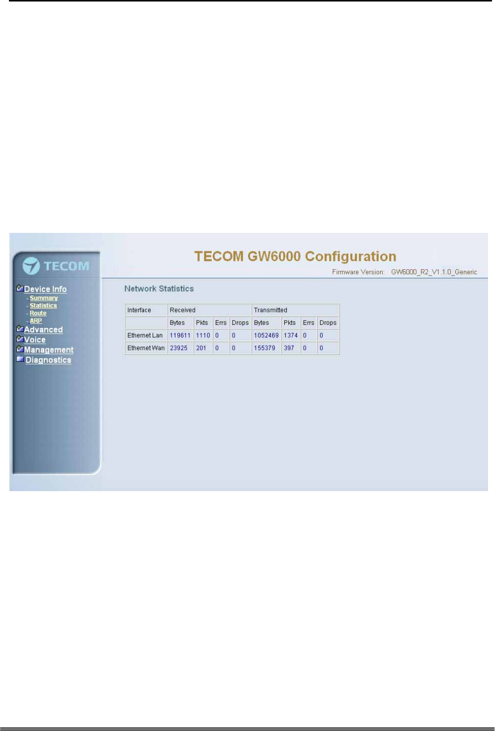
6.3.2 Statistics
In this page (Figure 6-5) you can get the network statistics of the specific interface.
Figure 6-5. Device Info – Statistics
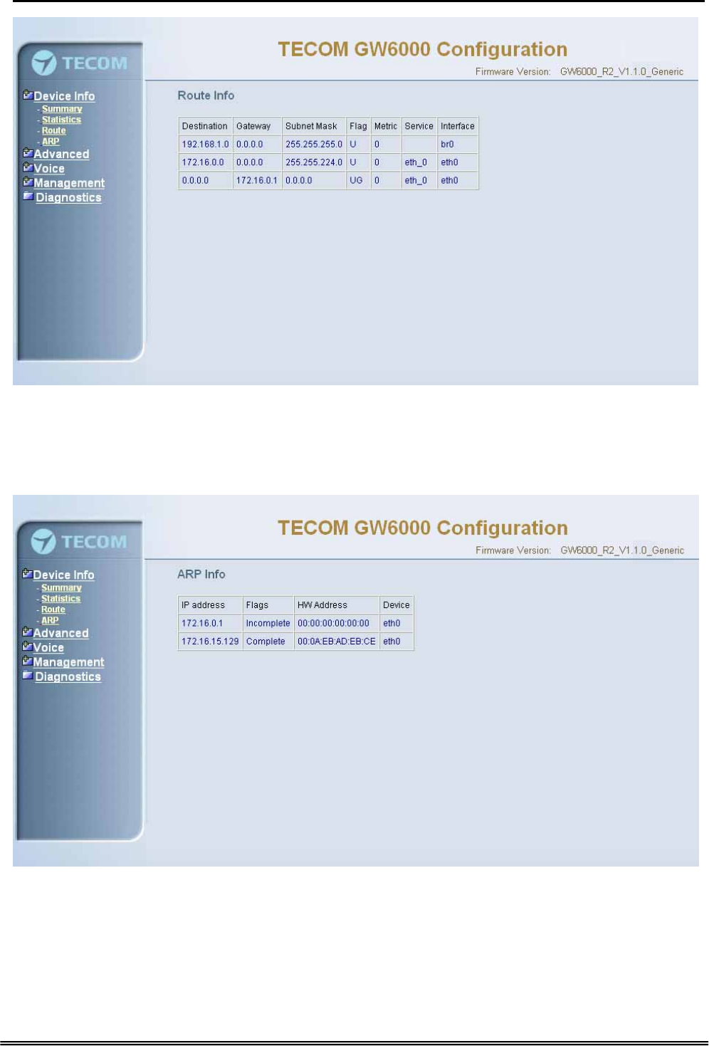
6.3.3 Route
In this page (Figure 6-6) you can get the IP route information of the device.
Copy Right 2006 Tecom, Co. LTD. All rights reserved Page 31 of 107
GW 6000 Administrative Guide Configuration
Figure 6-6. Device Info – Route
6.3.4 ARP
This page (Figure 6-7) shows an ARP table which map IP network addresses to
hardware addresses used by data link level protocol.
Figure 6-7. Device Info – ARP
Copy Right 2006 Tecom, Co. LTD. All rights reserved Page 32 of 107
GW 6000 Administrative Guide Configuration
6.4 Advanced Setup
Advanced Setup allows system administrator to configure the following topics:
z LAN
z WAN
z Route
- Static Route
- RIP
z NAT
- Virtual Servers
- Port Trigger
- DMZ
z Security
- Incoming Filtering
- Outgoing Filtering
- Parental Service
z Quality of Service
- Traffic Class
- Bandwidth Control
z Dynamic DNS
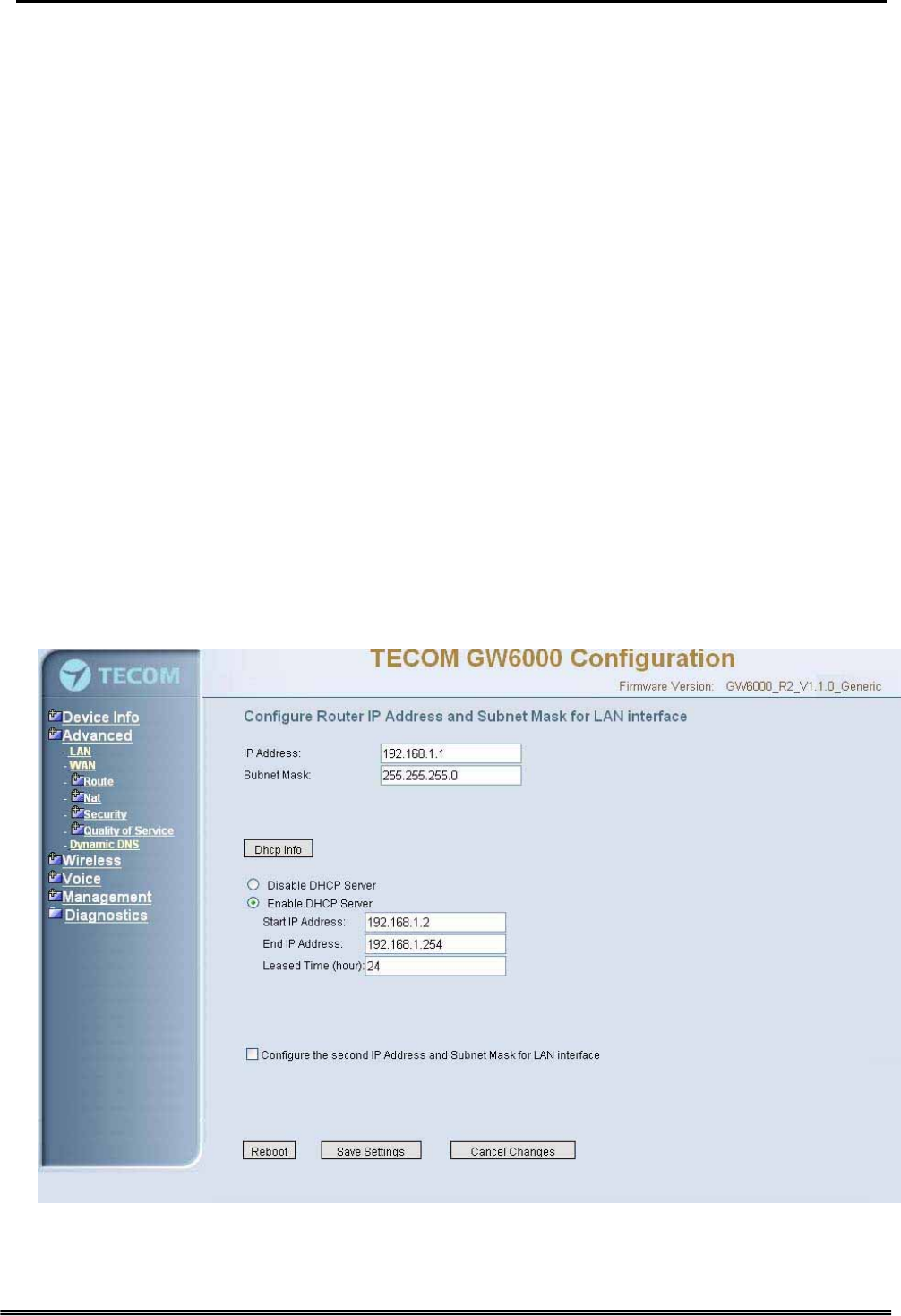
6.4.1 LAN
It allows you to set LAN IP and Subnet Mask for LAN interface (Figure 6-8-1). You can
also enable or disable DHCP Server and configure related settings for that mode.
Figure 6-8-1. Advanced Setup – LAN
Copy Right 2006 Tecom, Co. LTD. All rights reserved Page 33 of 107
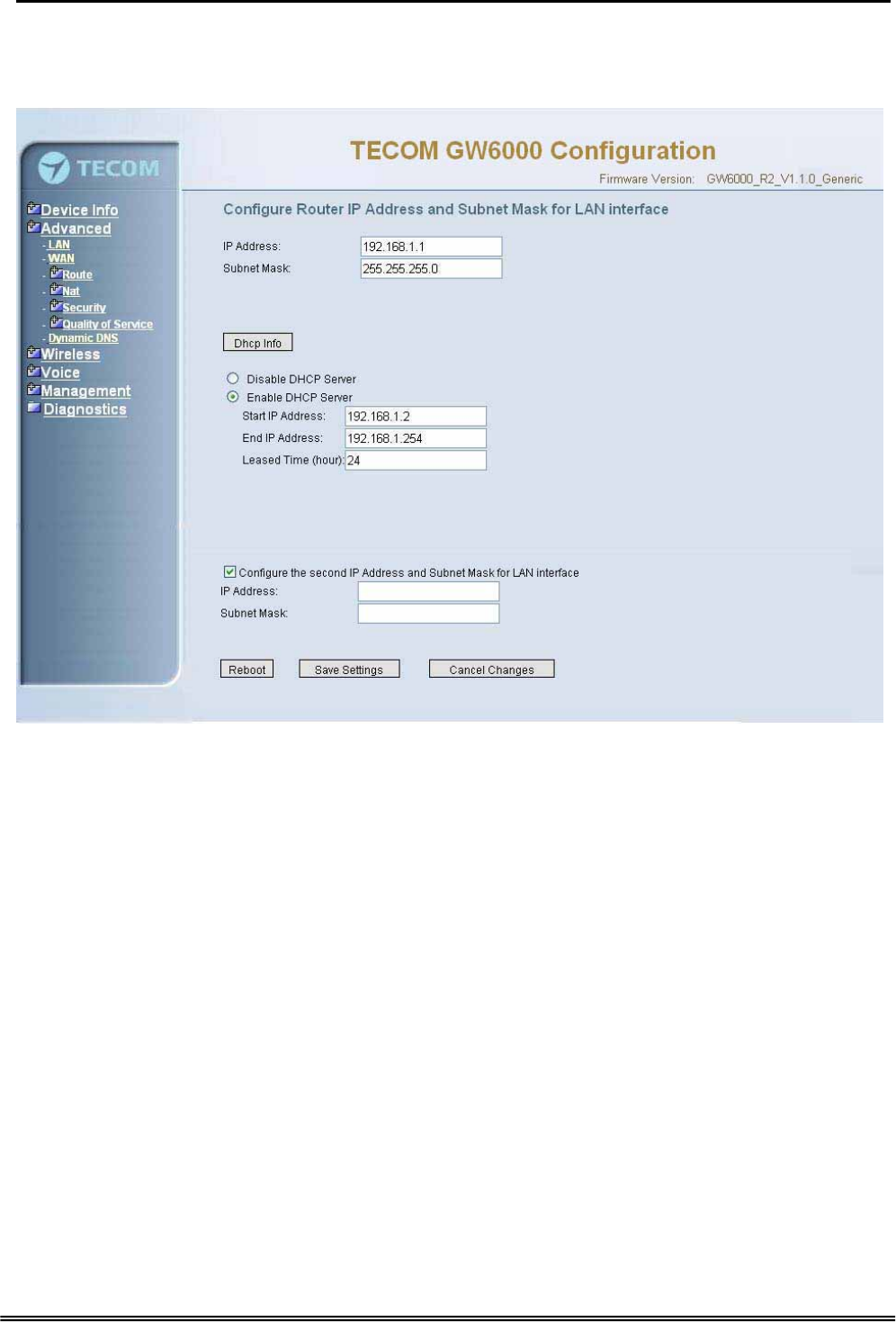
GW 6000 Administrative Guide Configuration
If necessary, check the “Secondary IP” to configure the secondary IP address and
Subnet Mask for LAN interface (Figure 6-8-2). This IP address is used for management
only.
Figure 6-8-2. Advanced Setup – LAN (Secondary LAN IP checked)
6.4.2 WAN
There are three modes that you can give to WAN IP address: Static IP mode, DHCP
mode and PPPoE mode. You can also enable or disable Firewall and IGMP.
When the Firewall option is selected, you can configure firewall settings in the followed
Security directory. Or, the Security directory will hide and firewall settings is disabled.
Network Address Translation (NAT) allows you to share one Wide Area Network (WAN)
IP address for multiple computers on your Local Area Network (LAN). In GW6000, NAT
is default enabled and is not showing on the page to prevent it from being disabled.
This page shows the current existing WAN interfaces in the system is Static IP mode
(Figure 6-9-1).
Copy Right 2006 Tecom, Co. LTD. All rights reserved Page 34 of 107
GW 6000 Administrative Guide Configuration
Figure 6-9-1 Advanced Setup – WAN (Static IP Mode)
The Dynamic Host Configuration Protocol (DHCP) is an Internet protocol for automating
the configuration of computers that use TCP/IP. DHCP can be used to automatically
assign IP addresses, to deliver TCP/IP stack configuration parameters such as the
subnet mask and default router, and to provide other configuration information.
This page shows the current existing WAN interfaces in the system is DHCP mode
(Figure 6-9-2).
Figure 6-9-2 Advanced Setup – WAN (DHCP Mode)
This page shows the current existing WAN interfaces in the system is PPPoE mode
(Figure 6-9-3).
Copy Right 2006 Tecom, Co. LTD. All rights reserved Page 35 of 107
GW 6000 Administrative Guide Configuration
Figure 6-9-3 Advanced Setup – WAN (PPPoE Mode)
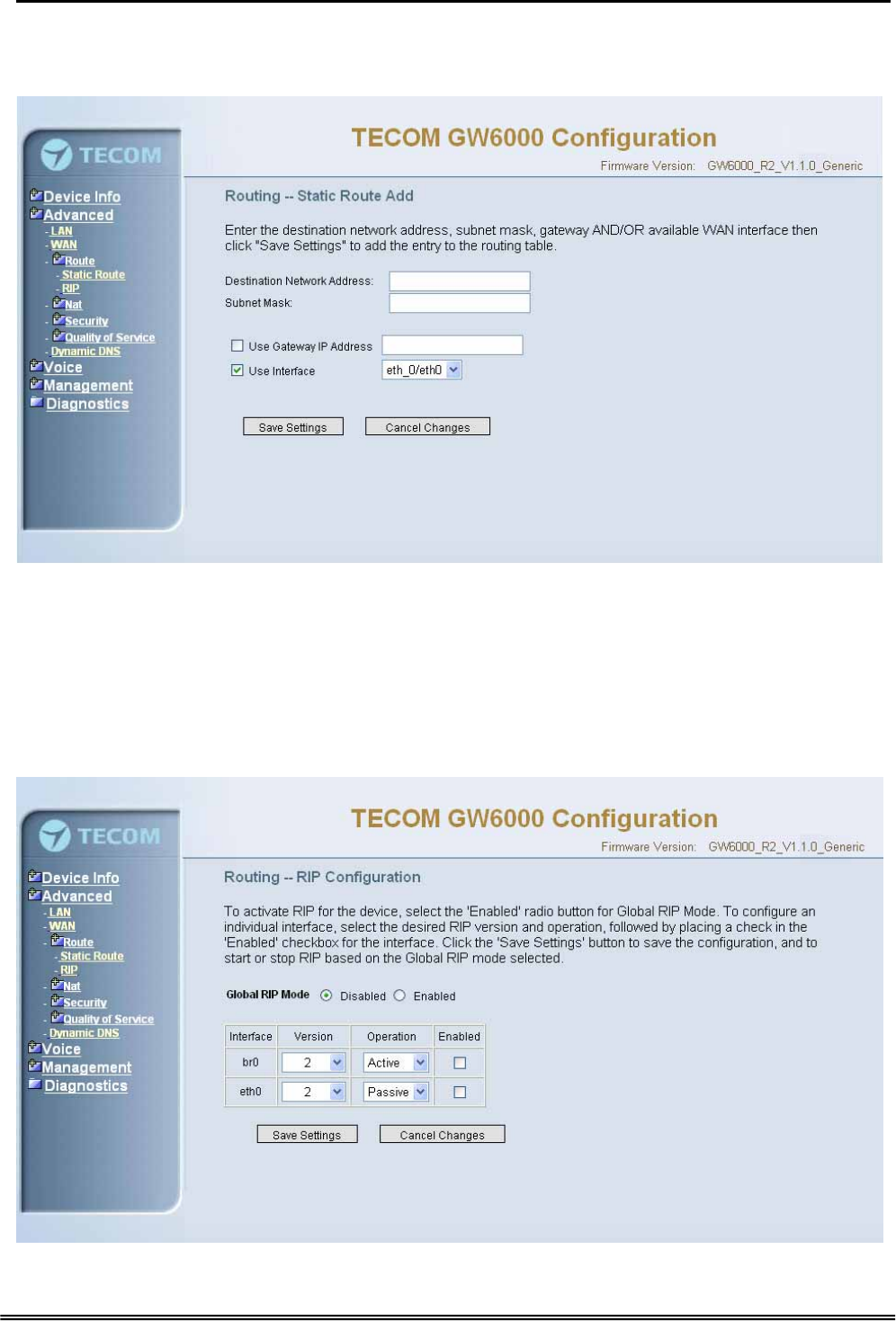
6.4.3 Route
It’s separated into two parts: Static Route and RIP.
6.4.3.1 Static Route
Figure 6-10-1. Advanced Setup – Route – Static Route
Copy Right 2006 Tecom, Co. LTD. All rights reserved Page 36 of 107
GW 6000 Administrative Guide Configuration
Click on Add to create a new Static Route. Enter the destination network address,
subnet mask, gateway AND/OR available WAN interface then click "Save Settings" to
add the entry to the routing table. (Figure 6-10-1, 6-10-2)
Figure 6-10-2. Advanced Setup – Route – Static Route – Add
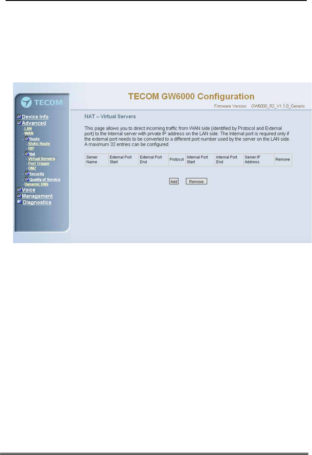
6.4.3.2 RIP
To activate RIP for the device, select the 'Enabled' radio button for Global RIP Mode. To
configure an individual interface, select the desired RIP version and operation, followed
by placing a check in the 'Enabled' checkbox for the interface. Click the 'Apply' button to
save the configuration, and to start or stop RIP based on the Global RIP mode selected.
(Figure 6-11)
Figure 6-11. Advanced Setup – Route – RIP
Copy Right 2006 Tecom, Co. LTD. All rights reserved Page 37 of 107
GW 6000 Administrative Guide Configuration
6.4.4 NAT
It’s separated into three parts: Virtual Servers, Port Trigger, and DMZ.
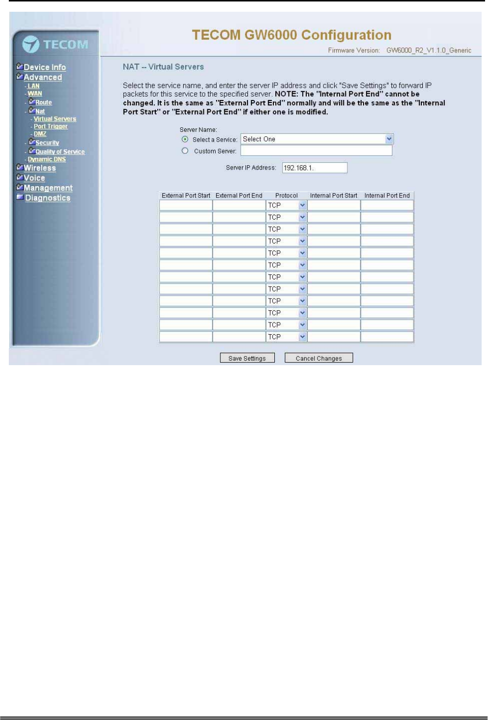
6.4.4.1 Virtual Servers
Virtual Server allows you to direct incoming traffic from WAN side (identified by Protocol,
IP address and service port) to the internal server with private IP address on the LAN
side. The Internal port is required only if the external port needs to be converted to a
different port number used by the server on the LAN side. (Figure 6-12-1, Figure 6-12-2)
Figure 6-12-1. Advanced Setup – NAT – Virtual Servers
Copy Right 2006 Tecom, Co. LTD. All rights reserved Page 38 of 107
GW 6000 Administrative Guide Configuration
Figure 6-12-2. Advanced Setup – NAT – Virtual Servers – Add
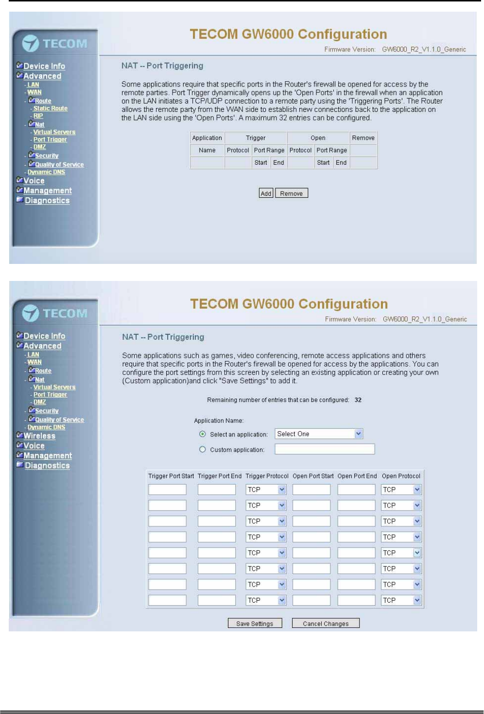
6.4.4.2 Port Triggering
Some applications require that specific port(s) in the Router's firewall be opened for
access by the remote parties. Port Trigger dynamically opens up the 'Open Ports' in the
firewall when an application on the LAN initiates a TCP/UDP connection to a remote
party using the 'Triggering Ports'. The Router allows the remote party from the WAN
side to establish new connections back to the application on the LAN side using the
'Open Ports'. (Figure 6-13-1, 6-13-2)
Copy Right 2006 Tecom, Co. LTD. All rights reserved Page 39 of 107
GW 6000 Administrative Guide Configuration
Figure 6-13-1. Advanced Setup – NAT – Port Triggering
Figure 6-13-2. Advanced Setup – NAT – Port Triggering – Add
Copy Right 2006 Tecom, Co. LTD. All rights reserved Page 40 of 107
GW 6000 Administrative Guide Configuration
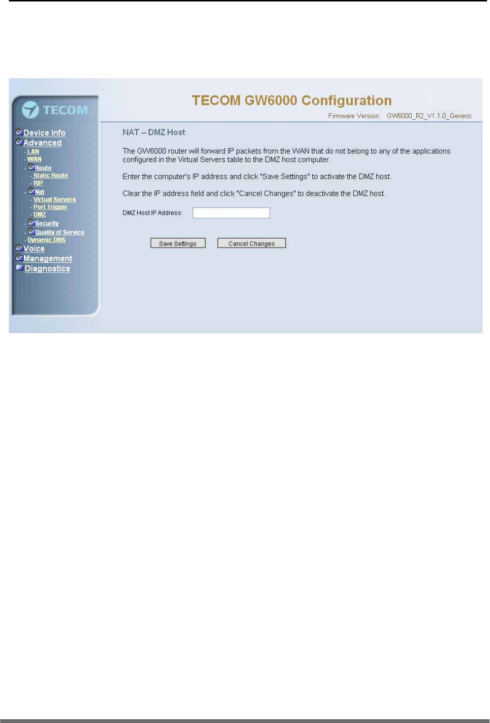
6.4.4.3 DMZ
The GW6000 will forward IP packets from the WAN that do not belong to any of the
applications configured in the Virtual Servers table to the DMZ host computer. (Figure 6-
14)
Figure 6-14. Advanced Setup – NAT – DMZ
6.4.5 Security
The configuration display only when WAN page’s security option is selected. It’s
separated into three parts: Incoming Filter, Output Filter, and Parental Control.
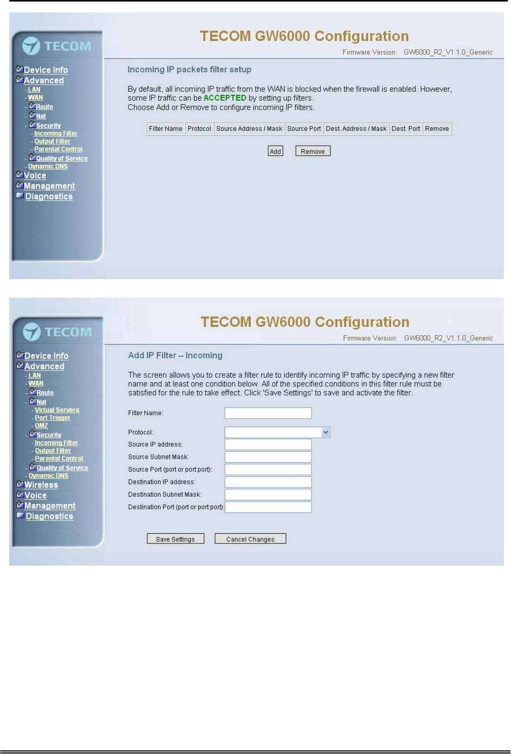
6.4.5.1 Incoming Filter
It allows the users to create a filter rule to identify incoming IP traffic by specifying a new
filter name and at least one condition. All of the specified conditions in this filter rule
must be satisfied for the rule to take effect. (Figure 6-15-1, Figure 6-15-2)
By default, all incoming IP traffic from the WAN will be blocked if it is not consistent with
the incoming filter rules. In fact, GW6000 has opened some necessary ports such as
web port, sip ports and rtp ports, to make sure that voice application can communicate
well.
Copy Right 2006 Tecom, Co. LTD. All rights reserved Page 41 of 107
GW 6000 Administrative Guide Configuration
Figure 6-15-1. Advanced Setup – Security – Incoming IP Filtering
Figure 6-15-2. Advanced Setup – Security – Incoming IP Filtering – Add
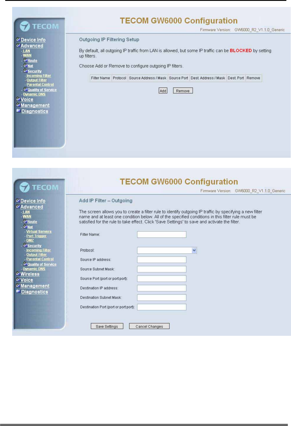
6.4.5.2 Output Filter
It allows the users to create a filter rule to identify outgoing IP traffic by specifying a new
filter name and at least one condition. All of the specified conditions in this filter rule
must be satisfied for the rule to take effect. (Figure 6-16-1, Figure 6-16-2)
Copy Right 2006 Tecom, Co. LTD. All rights reserved Page 42 of 107
GW 6000 Administrative Guide Configuration
Figure 6-16-1. Advanced Setup – Security – Outgoing IP Filtering
Figure 6-16-2. Advanced Setup – Security – Outgoing IP Filtering – Add
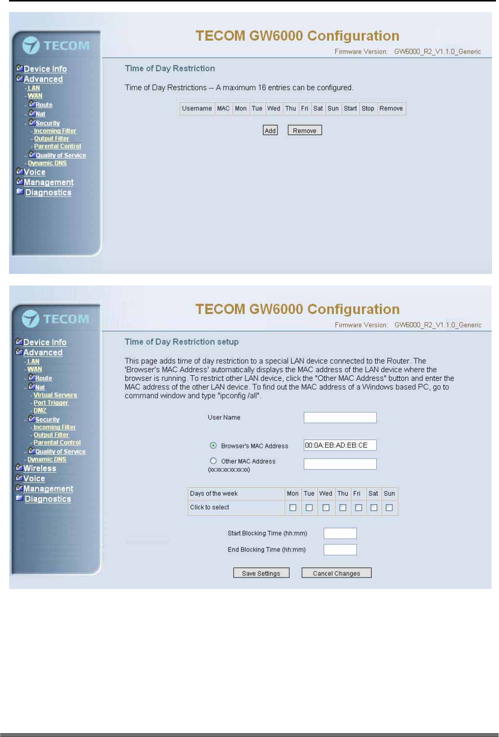
6.4.5.3 Parental Control
It adds time restriction to a special LAN device connected to the Router. The 'Browser's
MAC Address' automatically displays the MAC address of the LAN device where the
browser is running. To restrict other LAN device, click the "Other MAC Address" button
and enter the MAC address of the other LAN device. (Figure 6-17-1, Figure 6-17-2)
Copy Right 2006 Tecom, Co. LTD. All rights reserved Page 43 of 107
GW 6000 Administrative Guide Configuration
Figure 6-17-1. Advanced Setup – Security –Parental Control
Figure 6-17-2. Advanced Setup – Security –Parental Control – Add
6.4.6 Quality of Service
It’s separated into two parts: Traffic Class, and Bandwidth Control.
Copy Right 2006 Tecom, Co. LTD. All rights reserved Page 44 of 107
GW 6000 Administrative Guide Configuration
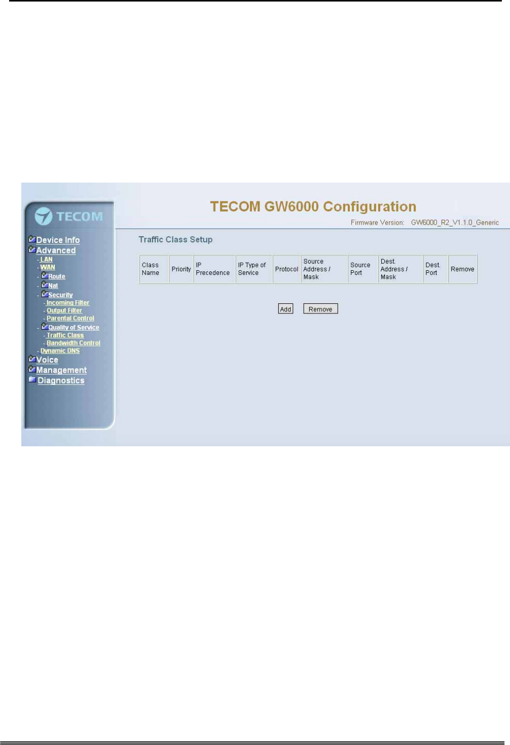
6.4.6.1 Traffic Class
Click on Add to create a class to identify the IP traffic by specifying at least one condition
below. If multiple conditions are specified, all of them should be satisfied to make sure
the rule will take effect. (Figure 6-18-1, Figure 6-18-2)
IP QoS is applied to the traffic from LAN to WAN; the traffic from WAN to LAN will not be
applied.
Enter the QoS class name for this policy. Define the priority for this policy, and the
priority will be used by the next bandwidth control setting. GW6000 will modify the IP
header with new IP Precedence and/or IP Type Of Service fields.
It’s a IP Layer QoS policy. At least (but not limited to) one condition must be configured.
Figure 6-18-1. Advanced Setup – Quality of Service – Traffic Class
Copy Right 2006 Tecom, Co. LTD. All rights reserved Page 45 of 107
GW 6000 Administrative Guide Configuration
Figure 6-18-2. Advanced Setup – Quality of Service – Traffic Class – Add
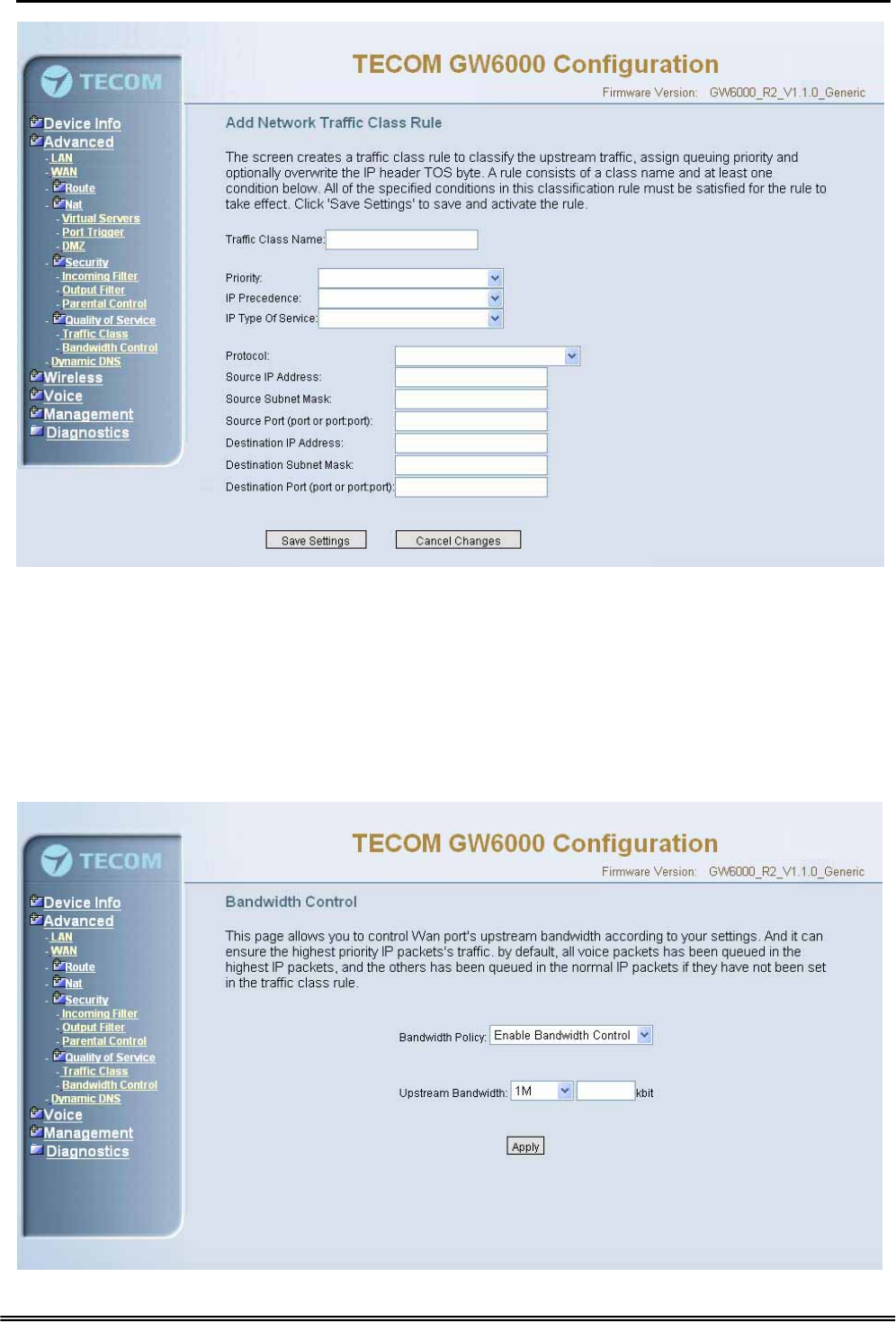
6.4.6.2 Bandwidth Control
This page allows you to control WAN port's upstream bandwidth according to your
settings (Figure 6-19). And it can ensure the highest priority IP packets' traffic firstly. By
default, all voice packets has been queued in the highest IP packets, and the others has
been queued in the normal IP packets if they have not been set in the priority field of the
traffic class rule.
Copy Right 2006 Tecom, Co. LTD. All rights reserved Page 46 of 107
GW 6000 Administrative Guide Configuration
Figure 6-19. Advanced Setup – Quality of Service – Bandwidth Control
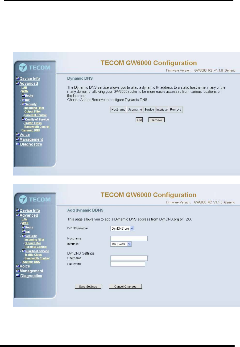
6.4.7 Dynamic DNS
The Dynamic DNS service allows you to alias a dynamic IP address to a static
hostname in any of the many domains, allowing your DSL router to be more easily
accessed from various locations on the Internet. (Figure 6-20-1, Figure 6-20-2)
Figure 6-20-1. Advanced Setup – Dynamic DNS
Figure 6-20-2. Advanced Setup – Dynamic DNS - Add
Copy Right 2006 Tecom, Co. LTD. All rights reserved Page 47 of 107
GW 6000 Administrative Guide Configuration
6.5 Wireless
This directory display only when wireless card is installed in your GW6000 board. Use
the Wireless screen to configure the GW6000 for wireless access. It is separated into 6
parts:
z Basic
z Security
z MAC Filter
z Wireless Bridge
z Advanced
z Station Info
The configurable items for each part would be described in the following.
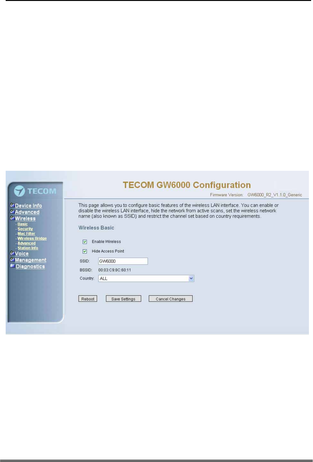
6.5.1 Basic
The page (Figure 6-21) allows you to configure basic feature of the wireless LAN
interface. You can enable or disable the wireless LAN interface, hide the network from
active scans, set the wireless network name (also known as SSID) and restrict the
channel set based on country requirement.
Figure 6-21. Wireless – Basic
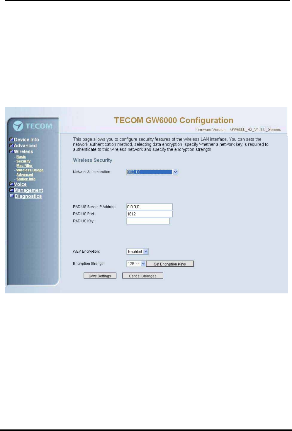
6.5.2 Security
The page allows you to configure security features of the wireless LAN interface. You
can set the network authorization method, select data encryption, specify whether a
network key is required to authenticate to this wireless network and specify the
encryption strength.
The following items will be configured in the page:
Network Authentication: Set the network Authentication method. 802.1X and WPA
require setting valid RADIUS parameters. WPA-PSK requires a valid WPA Pre-Shared
Key to be set. (Figure 6-22-1)
Copy Right 2006 Tecom, Co. LTD. All rights reserved Page 48 of 107
GW 6000 Administrative Guide Configuration
802.1X: As the IEEE standard for access control for wireless and wired LANs, 802.1x
provides a means of authentication and authorizing devices to attach to a LAN port.
This standard defines the Extensible Authentication Protocol (EAP), which uses a
central authentication server to authenticate each user on the network.
WPA/WPA2: The Wi-Fi Alliance put together WPA/WPA2 as a data encryption method
for 802.11 wireless LANs. WPA is an industry-supported, pre-standard version of
802.11i utilizing the Tempoal Key Integrity Protocol (TKIP), which fixes the problems
of WEP, including using dynamic keys.
WPA/WPA2 Pre-Shared Key: Set the WPA/WPA2 Pre-Shared Key (PSK).
WPA/WPA2 Group Rekey Interval: Set the WPA/WPA2 Group Rekey Interval in
seconds. Leave blank or set to zero to disable periodic re-keying.
Figure 6-22-1. Wireless – Security
Radius Server: Set the IP address of the RADIUS server to use for authentication and
dynamic key derivation.
RADIUS Server is responsible for receiving user connection requests, authenticating
the user, and then returning all of the configuration information necessary for the client
to deliver the server to the user.
Radius Port: Sets the UDP port number of the RADIUS server. The port number is
usually 1812 or 1645 and depends on the server.
Radius Key: Set the shared secret for the RADIUS connection.
WEP Encryption: Selecting Disabled disables WEP data encryption. Selecting
Enabled enables WEP data encryption and requires that a valid network key be set
and selected unless 802.1X is enabled.
Copy Right 2006 Tecom, Co. LTD. All rights reserved Page 49 of 107
GW 6000 Administrative Guide Configuration
WEP, short for Wired Equivalent Privacy, is a protocol for wireless LANs or local area
networks. This WEP is defined in the 802.11 Standard. WEP is designed so security
levels are maintained at the same level as the wired LAN. WEP’s aim is to provide
security by encrypting data over radio waves. WEP protects data as it’s transmitted
from one end point to another. WEP is used at two lowest layers, the data link and
physical layer. WEP is designed to make up for the inherent security in wireless
transmission as compared to wired transmission.
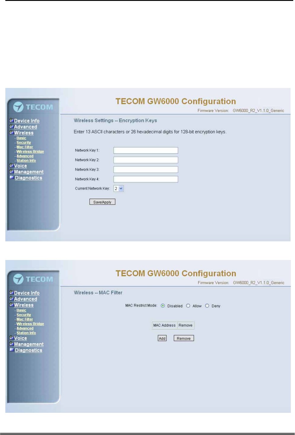
Shared Key Authentication: Set whether shared key authentication is required to
associate. A valid network key must be set and selected if required. (Figure 6-22-2)
Figure 6-22-2. Wireless – Security – Encryption Keys
6.5.3 MAC Filter
Figure 6-23-1. Wireless – MAC Filter
Copy Right 2006 Tecom, Co. LTD. All rights reserved Page 50 of 107
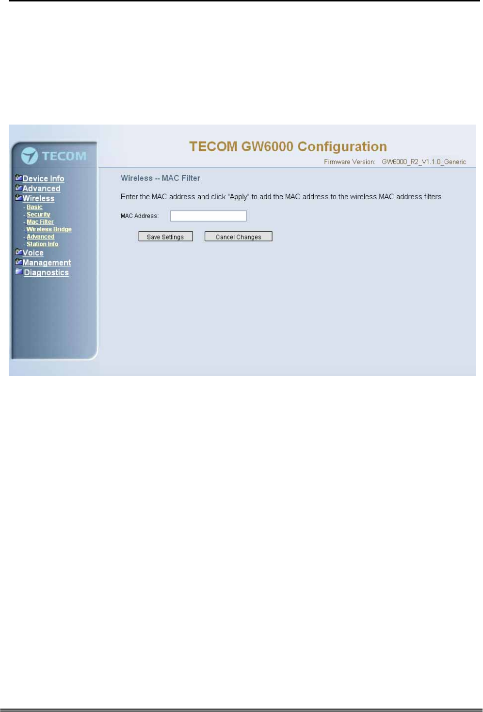
GW 6000 Administrative Guide Configuration
This page allows users to Add/Remove hosts with the specified MAC addresses that
are able or unable to access the wireless network. When users decide to use Allow,
only the MAC addressed in the user-defined list can access the wireless network.
When users use Deny, only the user specified MAC addresses are unable to access
to wireless network. And if the Disable option is selected, all users will be able to
access to wireless network.
Note: The MAC addresses in the list would immediately take effect when Allow or
Deny is checked.
Figure 6-23-2. Wireless – MAC Filter – Allow/Deny
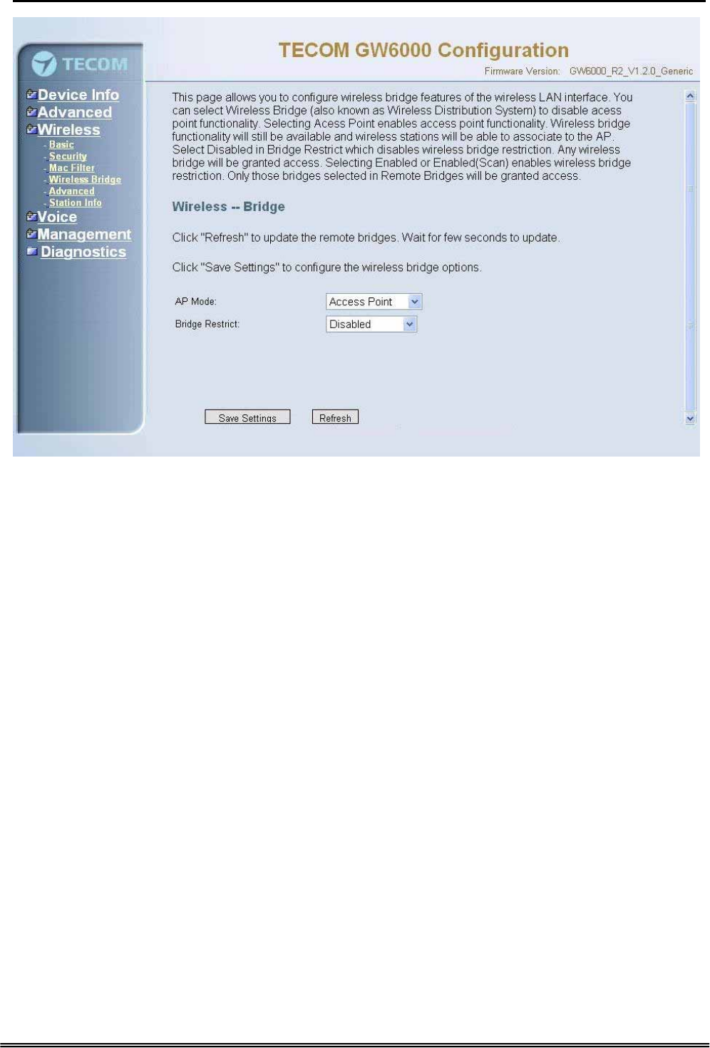
6.5.4 Wireless Bridge
It allows the users to configure wireless bridge features of the wireless LAN interface.
You can select Wireless Bridge (also known as Wireless Distribution System) to
disables access point functionality. Selecting Access Point enables access point
functionality. Wireless bridge functionality will still be available and wireless stations
will be able to associate to the AP. Select Disabled in Bridge restricts which disables
wireless bridge restriction. Any wireless bridge will be granted access. Selecting
Enabled or Enabled (Scan) enables wireless bridge restriction. Only those bridges
selected in Remote Bridges will be granted access.(Figure 6-24).
Copy Right 2006 Tecom, Co. LTD. All rights reserved Page 51 of 107
GW 6000 Administrative Guide Configuration
Figure 6-24. Wireless – Wireless Bridge
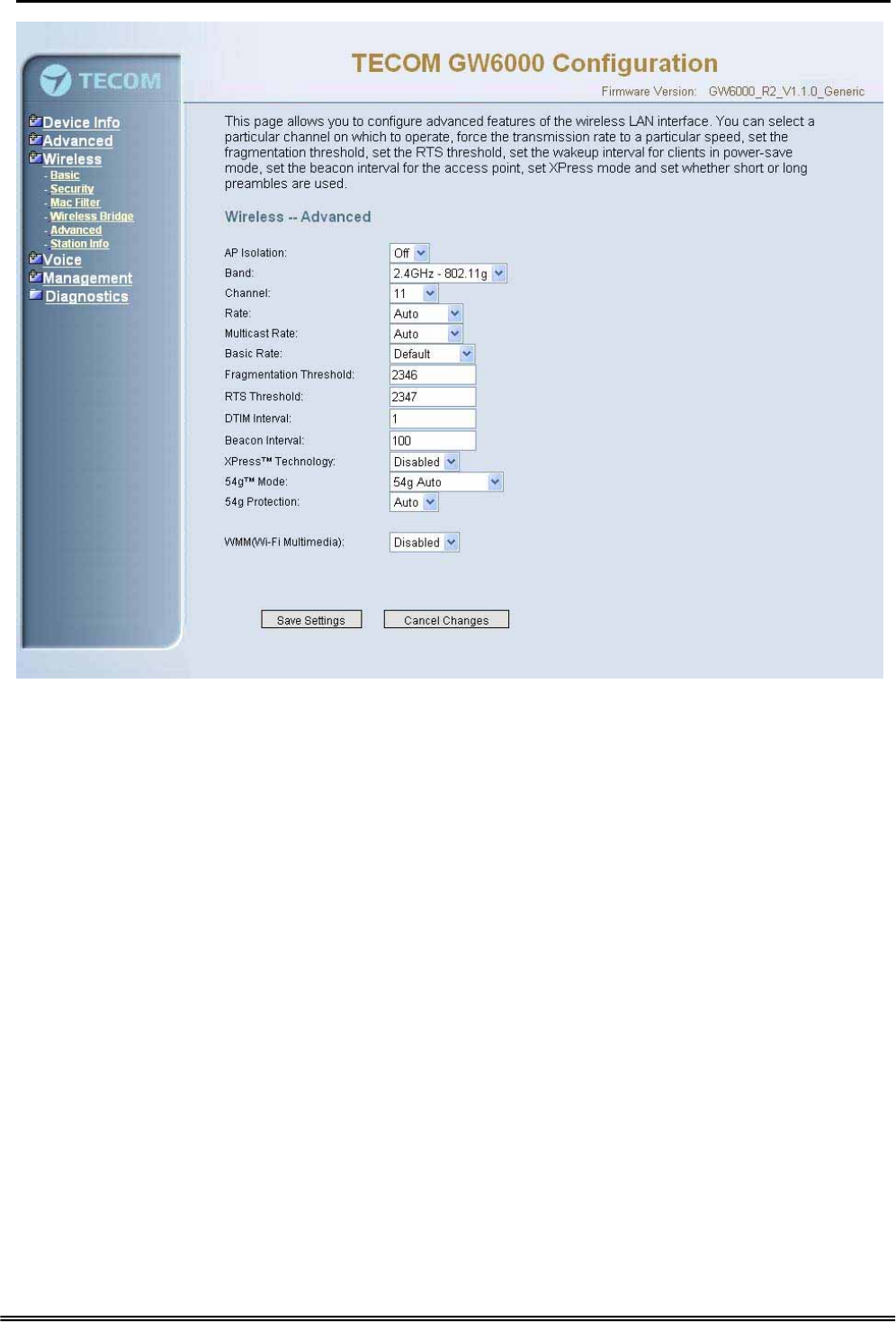
6.5.5 Advanced
It allows you to configure advanced features of the wireless LAN interface. You can
select a particular channel on which to operate, force the transmission rate to a
particular speed, set the fragmentation threshold, set the RTS threshold, set the wakeup
interval for clients in power-save mode, set the beacon interval for the access point, set
XPress mode and set whether short or long preambles are used
Channel: Select the appropriate channel from the list provided to correspond with your
network settings. All devices in your wireless network must use the same channel in
order to function correctly.
Rate: The default setting is Auto. The range is from 1 to 54Mbps. The rate of data
transmission should be set depending on the speed of your wireless network. You can
select from one transmission speed, or keep the default setting, Auto, to have the IAD
automatically use the fastest possible data rate.
Multicast Rate: The default setting is 54Mbps. The range is from 1 to 54Mbps. The
rate of data transmission should be set depending on the speed of your wireless
network. You can select from one transmission speed, or keep the default setting, to
have the IAD automatically use the fastest data rate for multicast packets.
Basic Rate: Select the basic rate that wireless clients must support.
Fragmentation Threshold: This value should remain at its default setting of 2346. The
range is 256~2346 bytes. It specifies the maximum size for a packet before data is
fragmented into multiple packets. If you experience a high packet error rate, you may
slightly increase the Fragmentation Threshold. Setting this value too low may result in
poor network performance. Only minor modifications of this value are recommended.
Copy Right 2006 Tecom, Co. LTD. All rights reserved Page 52 of 107
GW 6000 Administrative Guide Configuration
Figure 6-25. Wireless – Advanced
RTS Threshold: This value should remain at its default setting of 2347. The range is
0~2347 bytes. Should you encounter inconsistent data flow, only minor modifications
are recommended. If a network packet is smaller than the packet RTS threshold size,
the RTS/CTS mechanism will not be enabled. The IAD sends Request of Send (RTS)
frames to a particular receiving station and negotiates the sending of a data frame.
After receiving an RTS, the wireless station responds with a Clear to Send (CTS)
frame to acknowledge the right to begin transmission.
DTIM Interval: The default value is 3. This value, between 1 and 255 milliseconds,
indicates the interval of the Delivery Traffic Indication Message (DTIM). A DTIM field is
a countdown field informing clients of the next window for listening to broadcast and
multicast messages. When the router has buffered broadcast or multicast for
associated clients, it sends the next DTIM with a DTIM Interval value. Its clients hear
the beacons and awaken to receive the broadcast and multicast message.
Beacon Interval: The default value is 100. Enter a value between 1 and 65535
milliseconds. The Beacon Interval value indicates the frequency interval of the beacon.
A beacon is a packet broadcast by the router to synchronize the wireless network.
XPress™ Technology: Select to enable/disable this proprietary mode.
54g™ Mode: Select the mode to 54g Auto for the widest compatibility. Select the
mode to 54g Performance for the fastest performance among 54g certified equipment.
Set the mode to 54g LRS if you are experiencing difficulty with legacy 802.11b
equipment.
Copy Right 2006 Tecom, Co. LTD. All rights reserved Page 53 of 107
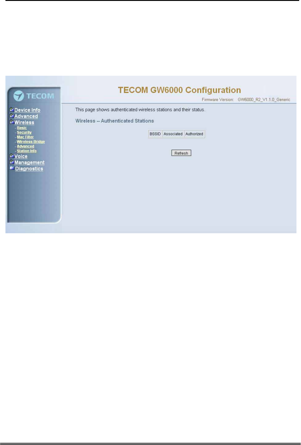
GW 6000 Administrative Guide Configuration
54g protection: In Auto mode the IAD will use RTS/CTS to improve 802.11g
performance in mixed 802.11g/802.11b networks. Turn protection off to maximize
802.11g throughput under most conditions.
WMM (WiFi Multimedia): Select to enable/disable the support.(Figure 6-25)
6.5.6 Station Info
Authenticated wireless stations and their status will be shown here.(Figure 6-26)
Figure 6-26. Wireless – Station Info
Copy Right 2006 Tecom, Co. LTD. All rights reserved Page 54 of 107

GW 6000 Administrative Guide Configuration
6.6 Voice
Use the Voice screen to configure the GW6000 function related parameters. It allows
system administrator to configure the following topics:
z Phone
- Phone Extension
- Extension Linekey
z Trunk
- IP Trunk
- Trunk Group
- Answering Positions
- Call Restriction Table
- Call Routing Table
z System
- Numbering Plan
- Service Mode
- Transmission
- IG Dynamic Discovery
- IG Expansion Table
z Voice Mail
- General
- Extension
- Holiday
- Advanced
The configurable items for each part would be described in the following.
6.6.1 Phone
Use the phone extension screen to configure GW6000’s phone extension authentication
and IP2007’s extension line key default setting.
6.6.1.1 Phone Extension
The GW6000 combines Proxy and Registrar servers in its application. The all phones
registered to the internal Registrar are set here. (Figure 6-27)
Copy Right 2006 Tecom, Co. LTD. All rights reserved Page 55 of 107
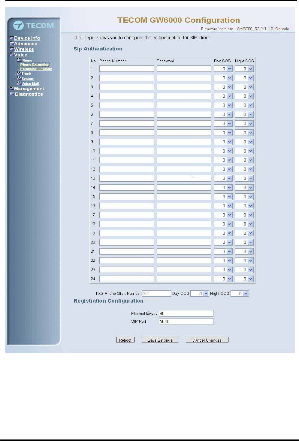
GW 6000 Administrative Guide Configuration
Figure 6-27. Voice – Phone – Phone Extension
SIP Authentication: It provides 24 IP phones registered.
Phone Number: The phone number is a station number. If it conflicts with the setting
in Numbering Plan, it fails to add or make the change. Its value range is limited by
Start Extension Number and End Extension Number settings in Numbering Plan
page.
Password: The user password of this phone. The length is up to 24 digits or
characters. It’s used for Digest Authentication.
Copy Right 2006 Tecom, Co. LTD. All rights reserved Page 56 of 107
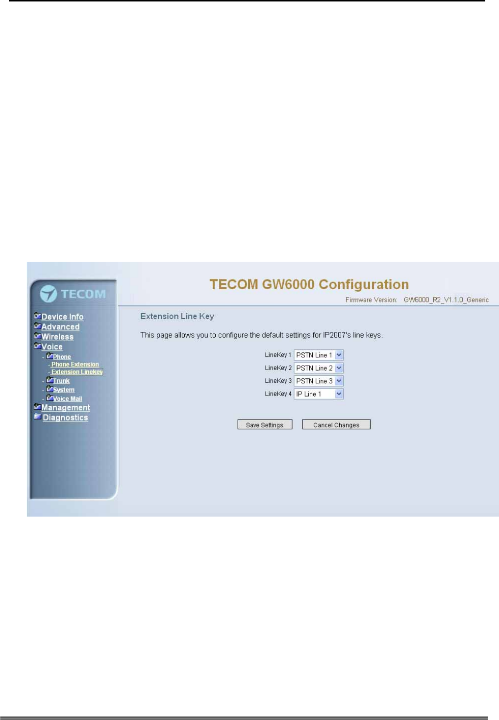
GW 6000 Administrative Guide Configuration
Day COS: The field assigns Class of Service for day mode operation. Acceptable
values are 0-7. At default, all extensions are unrestricted.
Night COS: The field assigns Class of Service for night mode operation. Acceptable
values are 0-7. At default, all extensions are unrestricted.
FXS Phone Start Number: It shows the FXS phone number. It’s programmed in
System – Numbering Plan.
Registration Configuration
Minimal Expire: the minimum refresh interval registrar time supported for these IP
phones managed by the Gateway Server.
SIP Port: The Gateway Server listens for requests on the SIP port. This port is used
for UDP application and 5060 is its recommended value.
6.6.1.2 Extension Linekey
This page allows you to configure the default settings for IP2007’s linekeys. While a
new-allocated IP2007 is registering to IG, IG will send these settings to the
phone.(Figure 6-28)
Figure 6-28. Voice – Phone – Extension Linekey
6.6.2 Trunk
Use the Trunk screen to configure the PSTN/IP Trunk function related parameters. It is
separated into 5 parts:
z IP Trunk
z Trunk Group
z Answering Positions
z Call Restriction Table
z Call Routing Table
Copy Right 2006 Tecom, Co. LTD. All rights reserved Page 57 of 107

GW 6000 Administrative Guide Configuration
6.6.2.1 IP Trunk
This page allows you to configure the proxy and registration server of IP Trunk, up to 8
lines of IP Trunk are supported. (Figure 6-29)
Copy Right 2006 Tecom, Co. LTD. All rights reserved Page 58 of 107
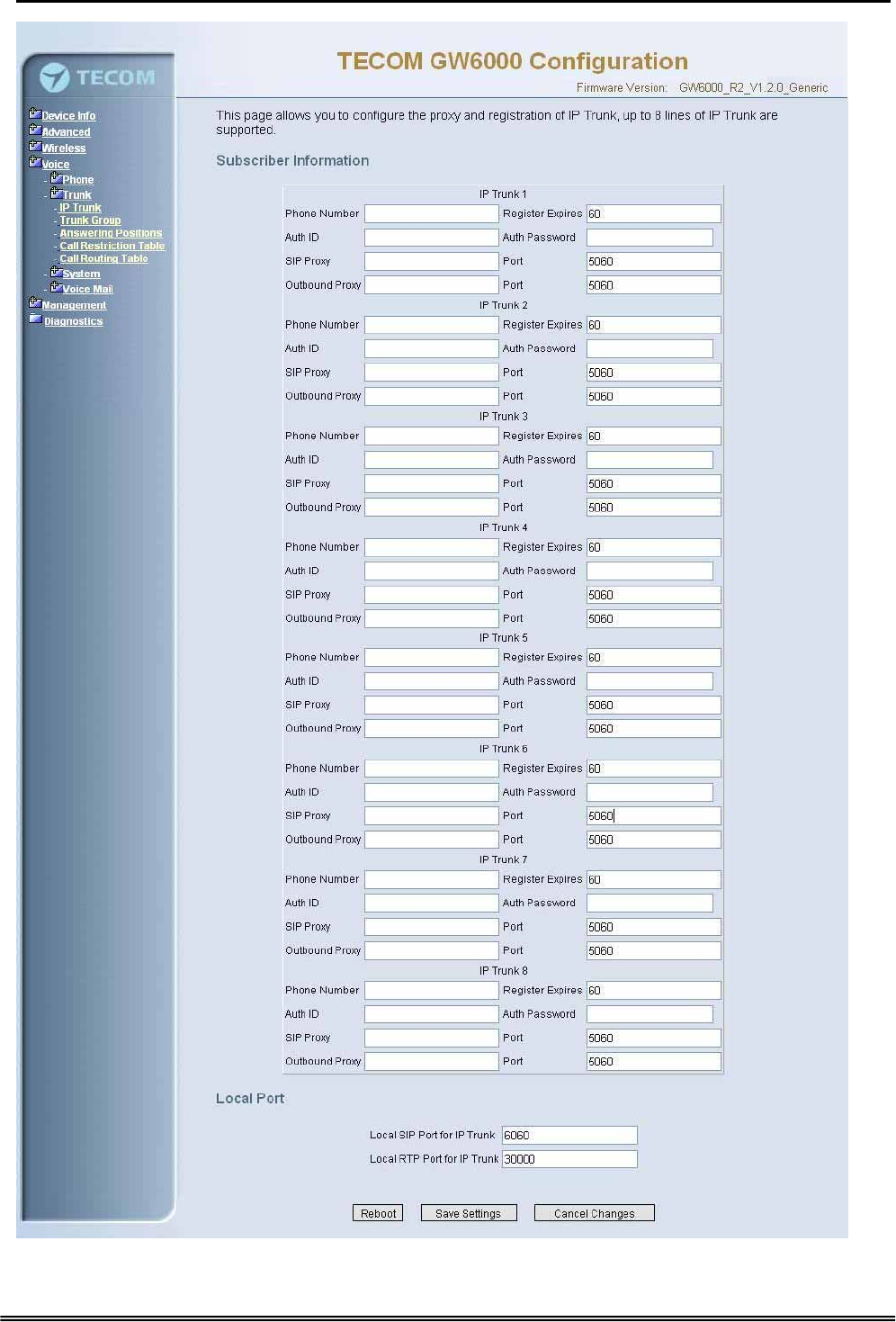
GW 6000 Administrative Guide Configuration
Figure 6-29. Voice – Trunk – IP Trunk
Copy Right 2006 Tecom, Co. LTD. All rights reserved Page 59 of 107

GW 6000 Administrative Guide Configuration
Subscriber Information
Trunk Number: The assigned phone number from Uplink Server.
Register Expires: how long the Gateway sends REGISTER to uplink registrar server.
It counts based on second.
Auth ID: The Account ID of registration to uplink server. It’s used for Digest
Authentication.
Auth Password: The Password of registration to uplink server. It’s used for Digest
Authentication.
SIP Proxy: the position of uplink registrar server. Digital IP address and domain
name are all supported.
SIP Proxy Port: SIP signal port of uplink registrar server.
Outbound Proxy: the address of uplink outbound proxy server. All sip request
packet will be sent to this server that will determine their next hops.
Outbound Proxy Port: SIP signal port of uplink outbound proxy server.
Local Port
Local SIP Port for IP Trunk: SIP control signal packet Port of IP Trunk Client.
Local RTP Port for IP Trunk: Real-Time Protocol packet Port of IP Trunk Client. It’s
the start RTP port address for these IP Trunks.
6.6.2.2 Trunk Group
This page allows you to configure the virtual Trunk Group, up to 4 Trunk Groups are
supported.(Figure 6-30)
Trunk Group & Label
This item allows you to assign physical Trunk to virtual Trunk Group. And you can
configure your personal string as incoming Caller ID number. For three PSTN lines
and eight IP lines you can choose from Group1 to Group 4.
Trunk Group Priority
This Item allows you to define 4 Trunk Group's interior priority. For four groups you
can choose IP first or PSTN first. This will take effect if call routing entry’s
destination has been set as Group choice.
Copy Right 2006 Tecom, Co. LTD. All rights reserved Page 60 of 107