Tekelek Europe 784 WiFi Module with integrated TCP/IP protocol stack User Manual 784 Installation Manual V1 0x
Tekelek Europe Ltd WiFi Module with integrated TCP/IP protocol stack 784 Installation Manual V1 0x
Contents
- 1. Installation Manual
- 2. User Manual Statements
Installation Manual
784 Module Installation Manual
TS-031-01 Page 1 of 11
784 Installation Manual
Author Rory Keating
Version 1.0
Status Draft
Approved by
Date 14-02-2017
784 Module Installation Manual
TS-031-01 Page 2 of 11
Modification History
Rev. Date Author Changes
1.0 09-02-2017 R. Keating
Input Documents and Information
Ref Document ID Version Date Description
1)
2)
3)
4)
References and Guidelines
Ref. Document ID Date Description
1)
2)
3)
4)
5)
6)
7)
8)
9)
10)
784 Module Installation Manual
TS-031-01 Page 3 of 11
Definitions and Acronyms
Acronym Description
PSU Power Supply Unit
V Voltage

784 Module Installation Manual
TS-031-01 Page 4 of 11
Contents
Modification History.......................................................................................................................2
Input Documents and Information...............................................................................................2
References and Guidelines..........................................................................................................2
Definitions and Acronyms.............................................................................................................3
1 Pin Definitions ...............................................................................................................................5
2Installing a TEK 784 Module to an Wi-fi Application PCB.....Error! Bookmark not defined.
2.1TEK 784 Module Footprint. ..................................................................................................8
2.2TEK 784 Module Example Footprint on carrier PCB...........................................................9
2.3TEK784 Module Layout Recommendations.......................................................................11
2.4SMT Recommendations. .....................................................................................................11
784 Module Installation Manual
TS-031-01 Page 5 of 11
1.
1 Pin Definitions
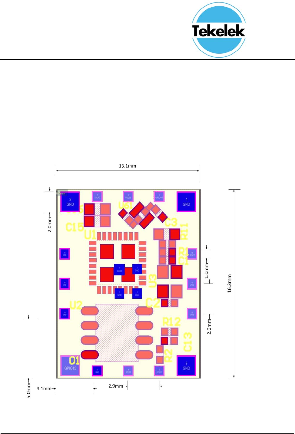
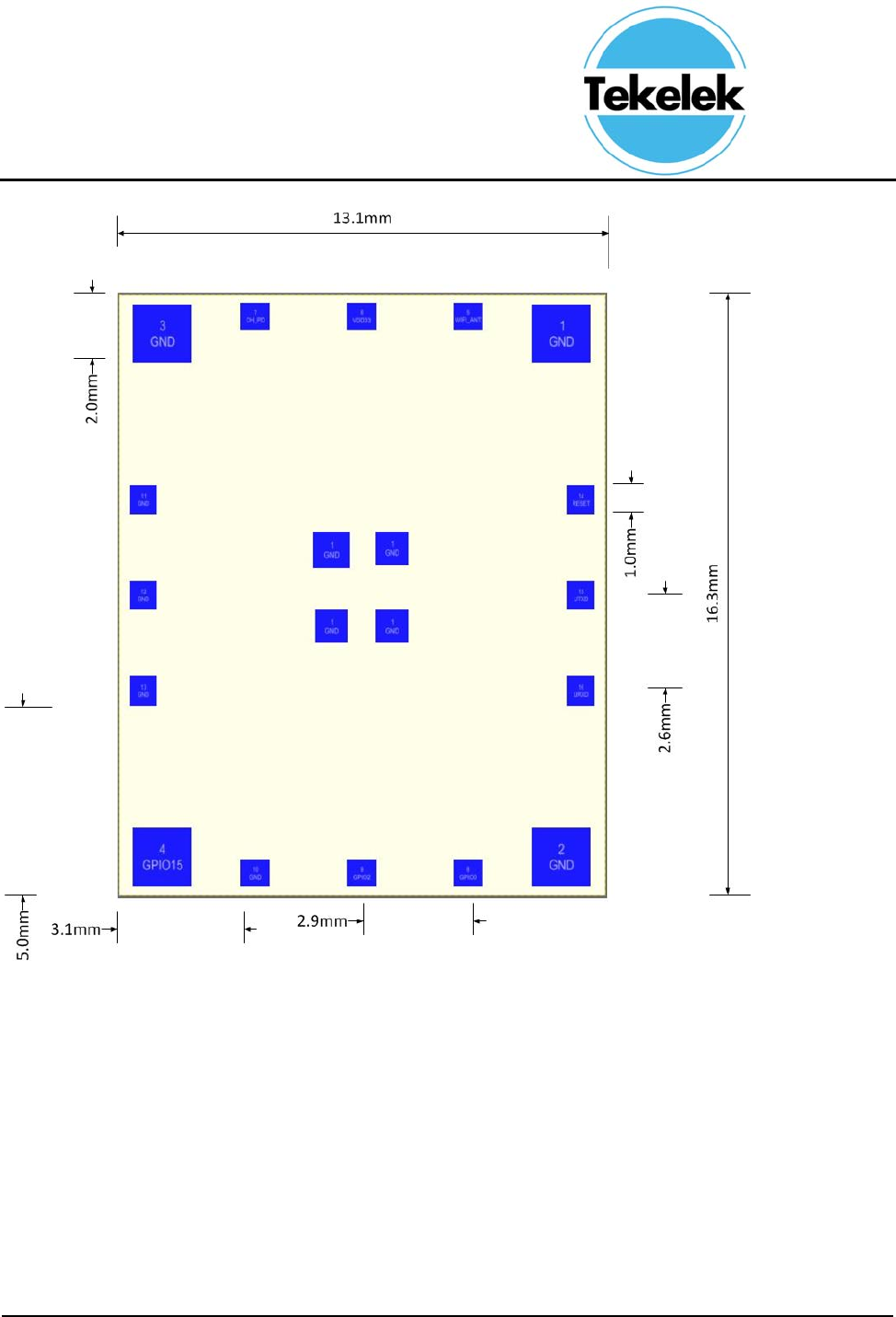
Figure1‐1showsthemechanicaldimensionsforthe16‐pinSMDpackage.
784 Module Installation Manual
TS-031-01 Page 6 of 11
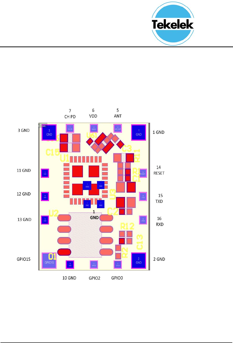
Figure1‐2showsthepinnamesforthe16‐pinSMDpackage.
784 Module Installation Manual
TS-031-01 Page 7 of 11
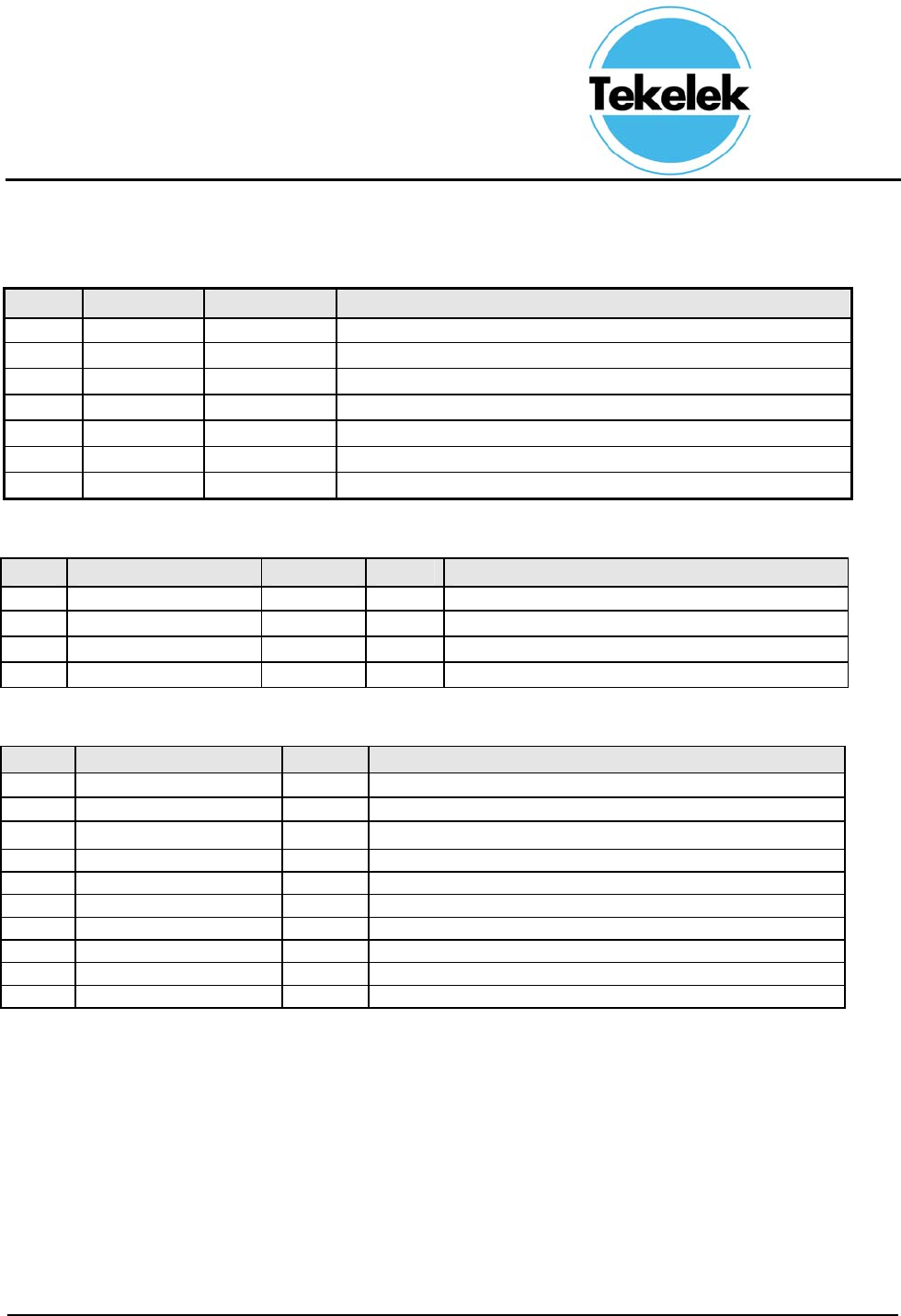
Table1‐1PinNamesandFunctions
PinNameTypeFunction
1GNDPPowerGround
2GNDPPowerGround
3GNDPPowerGround
4GPIO15I/OGeneralpurposeI/O15
5ANTI/ORFAntennaInterface
6VDDPPower3.0V~3.6V
7CHIP_PUIHigh:On,chipworksproperly
Low:Off,smallamountofcurrentconsumed.
8GPIO0I/OGeneralpurposeI/O0
9GPIO2I/OGeneralpurposeI/O2
10GNDPPowerGround
11GNDPPowerGround
12GNDPPowerGround
13GNDPPowerGround
14EXT_RSTBIExternalresetsignal(Lowvoltagelevel:Active)
15UARTTXDOUARTSerialTransmit
16UARTRXDIUARTSerialReceive

784 Module Installation Manual
TS-031-01 Page 8 of 11
2 TEK 784 Footprint
2.1 TEK 784 Module Footprint.
Use the Figure 6-1 as a footprint for installing TEK 784 module on PCB.
784 Module Installation Manual
TS-031-01 Page 9 of 11
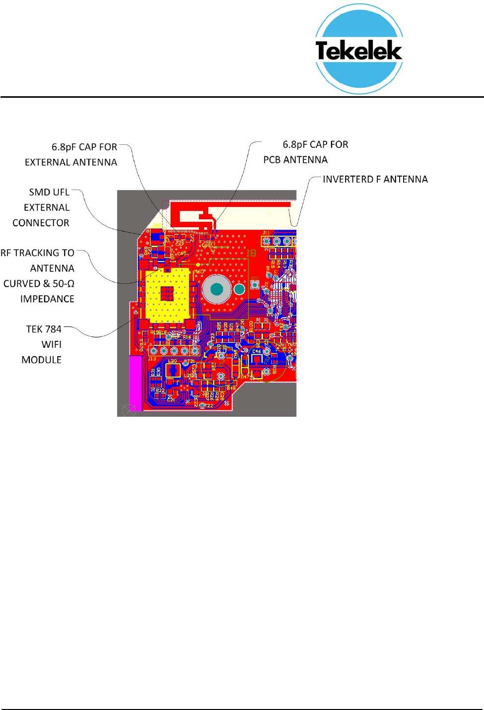
2.2 TEK 784 Module Example Footprint on carrier PCB.
784 Module Installation Manual
TS-031-01 Page 10 of 11
784 Module Installation Manual
TS-031-01 Page 11 of 11
Follow these RF trace routing recommendations:
a) RF traces must have 50-Ω impedance.
b) RF traces must not have sharp corners.
c) RF traces must have via stitching on the ground plane beside the RF trace on both sides.
d) RF traces must be as short as possible. The antenna, RF traces, and module must be on the edge
of the PCB product in consideration of the product enclosure material and proximity.
2.3 TEK784 Module Layout Recommendations.
Follow these module layout recommendations:
a) Ensure a solid ground plane and ground vias under the module for stable system an thermal dissipation.
b) Do not run signal traces underneath the module on the layer where the module is mounted.
c) Signal traces can be run on a third layer under the solid ground layer and beneath the module mounting.
d) Run the host interfaces with ground on the adjacent layer to improve the return path.
e) Route the signals as short as possible to the host.
2.4 SMT Recommendations.
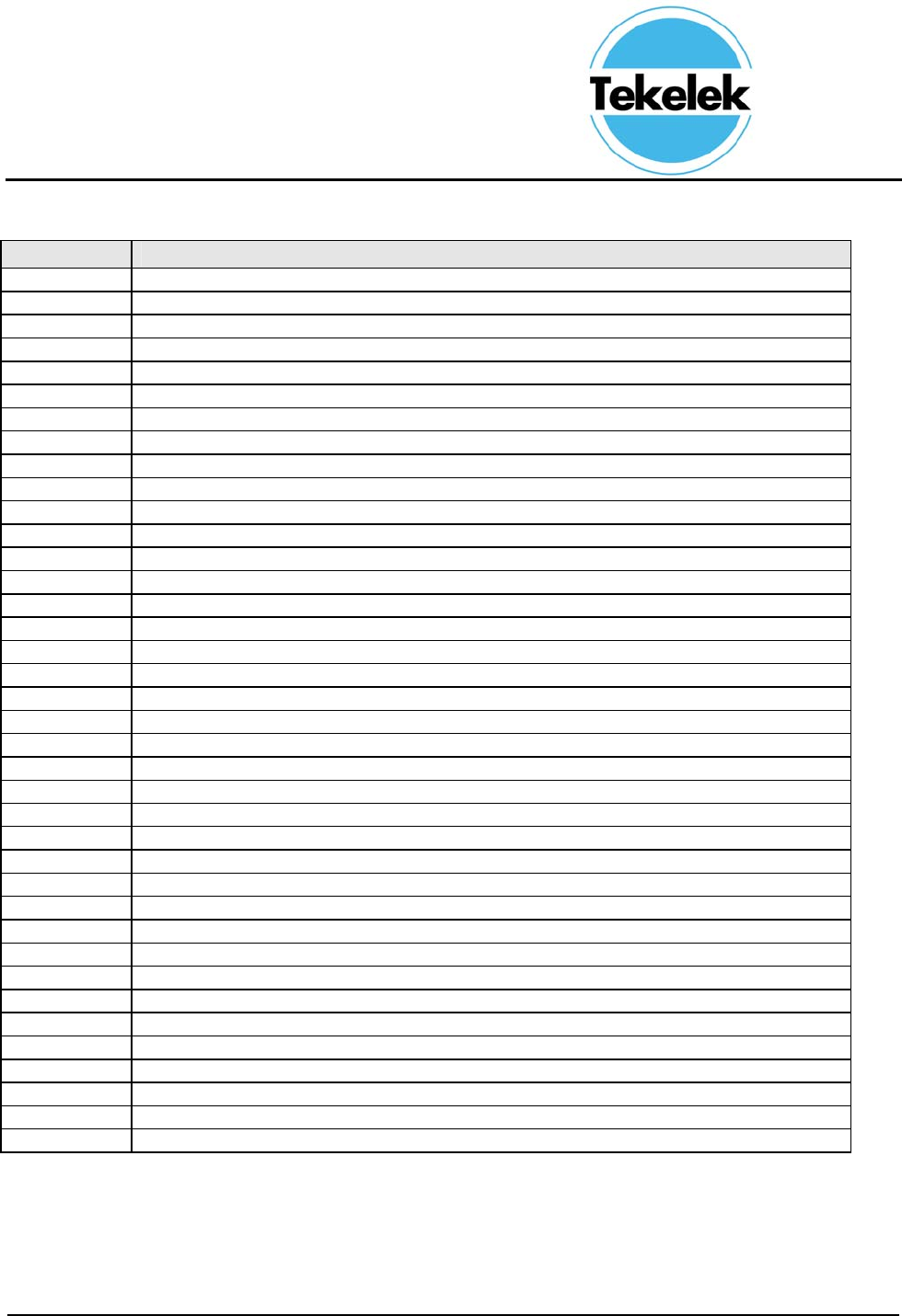
Table 7-3. Temperature Values for Reflow Profile
ItemTemperature°CTime(s)
Preheat140to20080to120
Soldering22060±10
PeakTemperature250maximum10
NOTE
It is not recommended to use conformal coating or similar material on the TEK 784 module.
This coating can lead to localized stress on the SMT solder connections inside the
module and impact the device reliability. Care should be taken during module assembly
process to the final PCB to avoid the presence of foreign material inside the module.