Telit Communications S p A BG864 Gateway Bluetooth – 802.15.4 User Manual SWS Gateway Product Description rev0
Telit Communications S.p.A. Gateway Bluetooth – 802.15.4 SWS Gateway Product Description rev0
Contents
- 1. User Manual
- 2. User Manual II
User Manual

SWS_Gateway Product Description
Rev. 0 – 2011/02/20

Reproduction forbidden without Telit Communications S.p.A. written authorization - All Rights Reserved page 2 of 73
Contents
1
Overview ....................................................................................................................................... 5
1.1 Reference .................................................................................................................................................5
1.2 General System Architecture ................................................................................................................5
2
Configuration 1 (BG864-2.4) ....................................................................................................... 6
2.1 Main Building Blocks .............................................................................................................................6
2.2 Main Building Blocks features ..............................................................................................................7
2.3 Physical Characteristics .........................................................................................................................9
2.3.1
Dimensions .......................................................................................................................................................... 9
2.3.2
Environmental Characteristics ............................................................................................................................. 9
2.4 Interface Description ..............................................................................................................................9
2.4.1
Overview .............................................................................................................................................................. 9
2.4.2
Supply Voltage .................................................................................................................................................. 10
2.4.3
Battery source .................................................................................................................................................... 10
2.4.4
Switching the BG864-2.4 ON and OFF ............................................................................................................. 11
2.4.4.1
Switching ON Procedure ........................................................................................................................... 11
2.4.4.2
Switching OFF .......................................................................................................................................... 11
2.4.5
Antenna .............................................................................................................................................................. 12
2.4.5.1
Bluetooth Antenna specifications .............................................................................................................. 12
2.4.5.2
Short Range Antenna Specifications ......................................................................................................... 12
2.4.6
Serial Port .......................................................................................................................................................... 12
2.4.6.1
RS232 standard interface connector .......................................................................................................... 13
2.4.7
Mini USB type connector .................................................................................................................................. 13
2.4.8
LEDindicators .................................................................................................................................................... 14
2.4.8.1
Bluetooth LED indicator ........................................................................................................................... 14
2.4.9
Push Button ........................................................................................................................................................ 15
3
Configuration 2 (GG864-2.4) ..................................................................................................... 16
3.1 Main Building Blocks ...........................................................................................................................16
3.2 Main Building Blocks features ............................................................................................................17
3.3 Physical Characteristics .......................................................................................................................18
3.3.1
Dimensions ........................................................................................................................................................ 18
3.4 Interface Description ............................................................................................................................19
3.4.1
Power connector ................................................................................................................................................ 19
3.4.2
Supply Voltage .................................................................................................................................................. 19
3.4.3
Battery source .................................................................................................................................................... 19
3.4.4
Switching the GG864-2.4 ON and OFF ............................................................................................................. 20
3.4.4.1
Switching ON ............................................................................................................................................ 20
3.4.4.2
Switching OFF .......................................................................................................................................... 20
3.4.5
Antenna .............................................................................................................................................................. 20
3.4.5.1
Antenna Output ......................................................................................................................................... 20
3.4.5.2
Antenna Connectors .................................................................................................................................. 20
3.4.5.3
GSM Antenna Requirements .................................................................................................................... 20
3.4.5.4
Short Range Antenna Requirements ......................................................................................................... 21
3.4.6
Serial Port .......................................................................................................................................................... 21

Reproduction forbidden without Telit Communications S.p.A. written authorization - All Rights Reserved page 3 of 73
3.4.6.1
RS232 standard interface connector .......................................................................................................... 21
3.4.7
Mini USB type connector .................................................................................................................................. 22
3.4.8
LED indicators ................................................................................................................................................... 22
3.4.8.1
GSM LED indicator .................................................................................................................................. 23
3.4.8.2
ARM LED indicator .................................................................................................................................. 23
3.4.8.3
Short Range LED indicator ....................................................................................................................... 24
3.4.9
Push Buttons ...................................................................................................................................................... 24
4
SW Specification ........................................................................................................................ 25
4.1.1
SW architecture .................................................................................................................................................. 25
4.1.1.1
SWS Gateway Application (Configuration 1 –no GSM) .......................................................................... 26
4.1.1.2
SWS Gateway Application (Configuration 2 – GSM) .............................................................................. 27
4.2 Host/gateway serial protocol ................................................................................................................29
4.2.1.1
Data-mode ................................................................................................................................................. 29
4.2.1.2
Command-mode ........................................................................................................................................ 30
4.3 Control Interface ..................................................................................................................................30
4.3.1
Stuff algorithm ................................................................................................................................................... 30
4.3.2
Message protocol ............................................................................................................................................... 31
4.3.3
Command and Response messages .................................................................................................................... 32
4.3.4
Commands/response description ........................................................................................................................ 35
4.3.4.1
Set Date/Time ........................................................................................................................................... 35
4.3.4.2
Get Date/Time ........................................................................................................................................... 35
4.3.4.3
Get Serial Number..................................................................................................................................... 36
4.3.4.4
Set GW SR parameters .............................................................................................................................. 36
4.3.4.5
Set DXT SR parameters ............................................................................................................................ 37
4.3.4.6
Set Gateway mode..................................................................................................................................... 38
4.3.4.7
Set GSM parameters ................................................................................................................................. 39
4.3.4.8
Set BT parameters ..................................................................................................................................... 40
4.3.4.9
Get Battery level ....................................................................................................................................... 40
4.3.4.10
Get HW/SW version ................................................................................................................................. 41
4.3.4.11
Get GSM parameters ................................................................................................................................. 41
4.3.4.12
Get GW SR parameters ............................................................................................................................. 42
4.3.4.13
Get DXT SR parameters ........................................................................................................................... 42
4.3.4.14
Scan for DXT ............................................................................................................................................ 43
4.3.4.15
Set Auto DXT Data ................................................................................................................................... 44
4.3.4.16
Get Status .................................................................................................................................................. 45
4.3.4.17
Set data mode ............................................................................................................................................ 46
4.3.4.18
SET Escape sequence from data mode ..................................................................................................... 46
4.3.4.19
Get DXT Data ........................................................................................................................................... 47
4.3.4.20
Add DXT list ............................................................................................................................................. 49
4.3.4.21
Get DXT list .............................................................................................................................................. 49
4.3.4.22
Remove DXT list ...................................................................................................................................... 50
4.3.4.23
Disable SIM PIN ....................................................................................................................................... 50
4.3.4.24
Turn Off SR .............................................................................................................................................. 51
4.3.4.25
Reboot ....................................................................................................................................................... 51
4.3.4.26
Standby ..................................................................................................................................................... 52
4.3.4.27
Deep Sleep ................................................................................................................................................ 52
4.3.4.28
Turn off ..................................................................................................................................................... 52
4.3.4.29
Reset .......................................................................................................................................................... 53
4.3.4.30
Get Auto DXT Data .................................................................................................................................. 53
4.3.4.31
Get Log File .............................................................................................................................................. 54
4.3.4.32
Get BT parameters .................................................................................................................................... 55
4.3.4.33
Scan for BT devices .................................................................................................................................. 56

Reproduction forbidden without Telit Communications S.p.A. written authorization - All Rights Reserved page 4 of 73
4.3.4.34
Add BT host .............................................................................................................................................. 56
4.3.4.35
Reset BT host ............................................................................................................................................ 57
4.3.4.36
Set GPRS host parameters ........................................................................................................................ 57
4.3.4.37
Set FTP parameters ................................................................................................................................... 58
4.3.4.38
Set Wakeup parameters ............................................................................................................................. 58
4.3.4.39
Get GPRS host parameters ........................................................................................................................ 59
4.3.4.40
Get FTP parameters................................................................................................................................... 60
4.3.4.41
Get Wakeup parameters ............................................................................................................................ 60
4.3.4.42
Flash SR .................................................................................................................................................... 61
4.3.4.43
Get Battery voltage ................................................................................................................................... 61
4.4 AT command console (C2) ...................................................................................................................62
5
Appendix: configuration 1 (BT) ................................................................................................. 63
5.1 BT pairing using Windows Mobile .....................................................................................................64
6
Appendix: configuration 2 (GSM) - controlled and autonomous modes .................................... 67
6.1 Controlled mode ...................................................................................................................................67
6.2 Autonomous mode ................................................................................................................................69
7
Conformity Assessment Issues ................................................................................................... 71
8
Document Change Log .............................................................................................................. 73
1 Overview
Scope of the document is detail technical specification, HW and SW for the 2 gateways BG864-2.4
and GG864-2.4.
1.1 Reference
[1]
Universal Gateway Specification v2B (Schlumberger Water Services- Divers Long range RF
architecture)
[2] Telit.ppt
[3] ZE60 Software interface specification
[4] cr 280912.pdf (meeting report 28/09/2009)
[5] cr 151209.pdf( meeting report 15/12/2009)
[6] protocol ideas.pdf
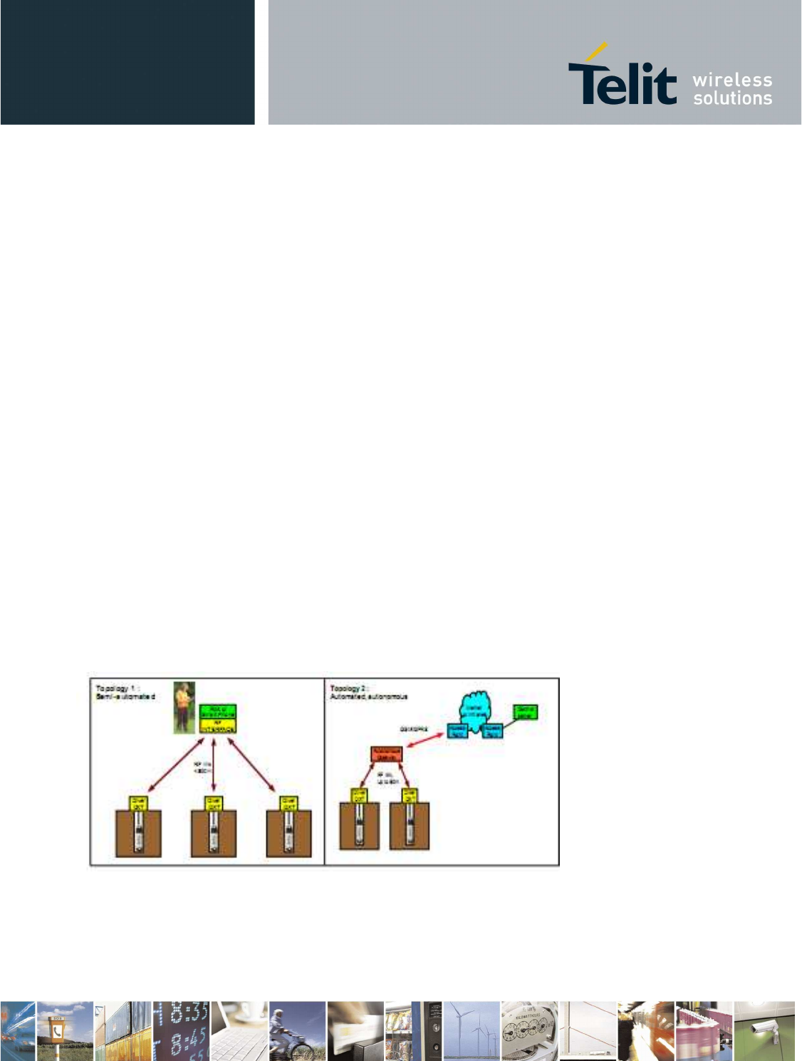
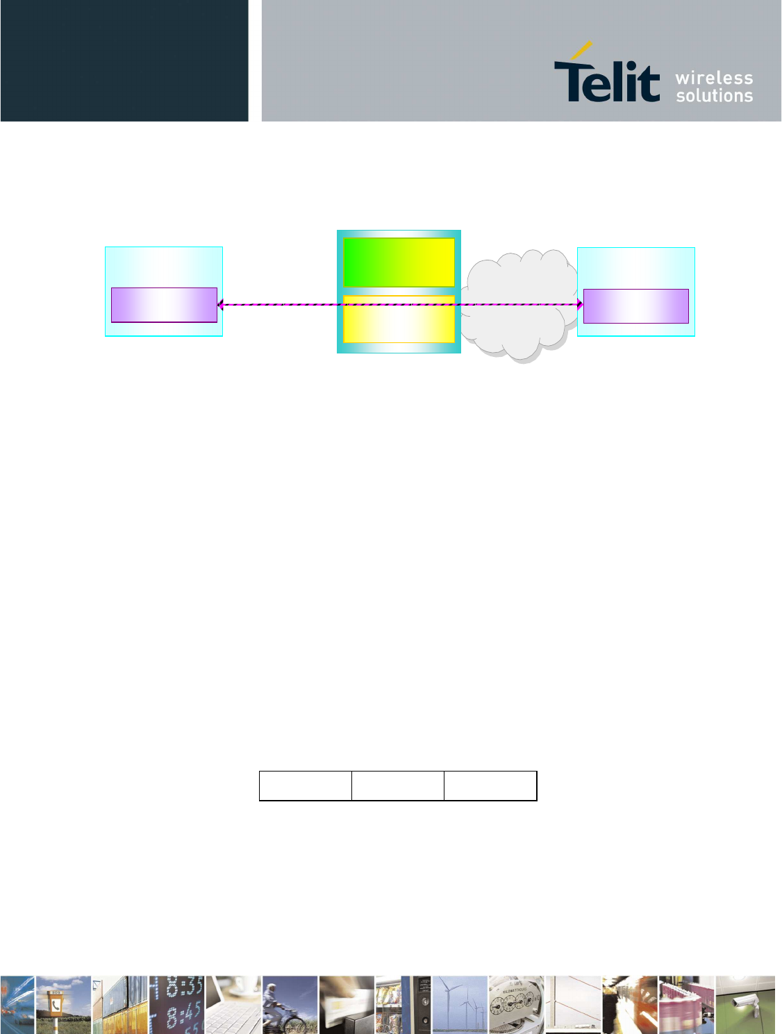
1.2 General System Architecture
The proposed product satisfy the topology scenarios 1 and 2 as specified in [1]
Figure 1 Topology Scenarios
Telit provides the gateway in two different configurations
Reproduction forbidden without Telit Communications S.p.A. written authorization - All Rights Reserved page 6 of 73
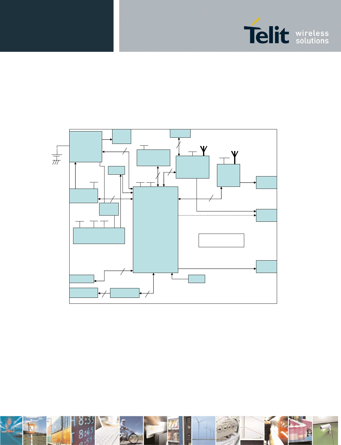
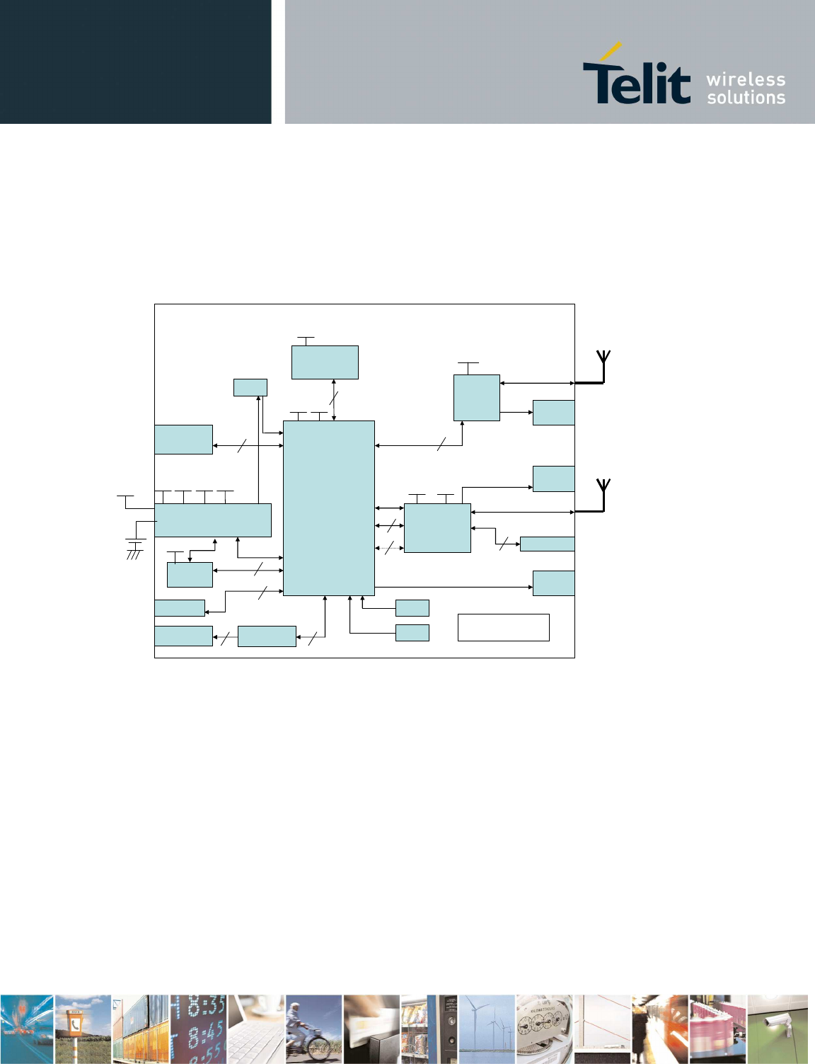
2 Configuration 1 (BG864-2.4)
JTAG
LED 1
UART
Mini-USB
Type B
USB
device
ZB Int.
Antenna
+
AP DATA
RS232
LED 3
UART
JTAG
1.8V 3.1V
ARM9
1.8V
MEMORY
3.1V
SPI BT
CONNECT.
SPI
#5 GPIO
#4 GPIO
BT Int.
Antenna
ZE60
3.1V
UART
#6 GPIO
Power
Supply
5.0V
3.1V 1.8V
Li-Ion
Batt.
LED 2
BT
Battery
Charger
+
Battery
Monitor
TRANSC.
RTC
ON/OFF
button
RESET
button
LED 4
3.8V
Config. 1
Figure 2 Configuration 1 Block Diagram
2.1 Main Building Blocks
•
ARM9 ATMEL AT91SAM9260
•
Memories (Flash and RAM)
•
ZE60 (w/o internal antenna)
•
BT chip CSR BC63B239A04-IQD-E4
•
External connectors for:
o
Mini-USB device
o
RS232

Reproduction forbidden without Telit Communications S.p.A. written authorization - All Rights Reserved page 7 of 73
o
Switch-slide Power-Supply
•
Internal antennas for:
o
BT
o
ZE60
•
Rechargeable Li-Ion battery
o
continuos charging application will be allowed
the battery charging will be stopped
when battery is completely charged.
•
Status Leds for:
o
BT
o
ZE60
o
Charger
o
ARM
•
Box
•
Power supply: external 4.5÷5.5V from mini-USB connector or 3.4÷4.2V from Li-Ion battery
•
Reset button
•
Operational Temperature: [-20°C +60°C]
•
Storage Temperature: [-40°C- +85°C]
2.2 Main Building Blocks features
•
ARM9 ATMEL AT91SAM9260
Based on the ARM926EJ-S™ ARM® Thumb® Processor
o
8-KByte Data Cache, 8-KByte Instruction Cache, Write Buffer
o
200 MIPS at 180 MHz
o
Memory Management Unit
o
EmbeddedICE™, Debug Communication Channel Support
o
External Bus Interface (EBI)
o
USB 2.0 Full Speed (12 Mbits per second) Device Port
o
USB 2.0 Full Speed (12 Mbits per second) Host Single Port in the 208-lead PQFP
o
Ethernet MAC 10/100 Base T
o
Fully-featured System Controller, including
o
Reset Controller, Shutdown Controller
o
Four 32-bit Battery Backup Registers for a Total of 16 Bytes
o
Clock Generator and Power Management Controller
o
Advanced Interrupt Controller and Debug Unit
o
Periodic Interval Timer, Watchdog Timer and Real-time Timer
o
Reset Controller (RSTC)
o
Clock Generator (CKGR)
o
Selectable 32,768 Hz Low-power Oscillator or Internal Low Power RC Oscillator on
o
Battery Backup Power Supply, Providing a Permanent Slow Clock
o
Power Management Controller (PMC)
•
Memories (Flash and RAM)
o
COMBO NAND SDRAM 128 MB FLASH/64 MB RAM
o
Memory will be shared for:
o
Code
o
Data

Reproduction forbidden without Telit Communications S.p.A. written authorization - All Rights Reserved page 8 of 73
o
Logging files (no dedicated memory will be provide for logging applications)
•
ZE60
o
Frequency band: 2400 - 2483.5 MHz
o
Power Supply:+2.4V-+3.6V
o
Output Power: 19dBm ± 1 dB on the whole band (selectable by software for compliance)
o
Consumption typ@3.6V :
o
Transmission :125mA
o
Reception : 35mA
o
Stand-by (32.768 khz On) : 2µA
o
Sleep (wake up on interruption): 1µA
o
Channel spacing: 5 MHz
o
Channel number : 16 , Channel 11 (2405MHz)
→
Channel 26 (2480MHz)
o
Technology : DSSS
o
Modulation: O-QPSK with half sine pulse shaping
o
Radio bit rate: 250 kbps
o
Sensitivity for PER(1%): -98dBm typ
o
Serial link:
o
Full Duplex, from 1200 to 115200 bps
o
7 or 8 bits, with or without parity, 1 or 2 stop bits
o
Protocol Type: RS-232, TTL level
o
Temperature: - 40+ 85°C
o
Relative humidity @ 25°C: 20-75%
o
Size: Rectangular 26 x 15 mm
o
Height: 3 mm
o
Weight: 1,7 g
o
PCB thickness: 0.8 mm
o
Components: All SMD components, on one side of the PCB.
o
Mounting: SMD, Half moons on the 4 external sides
o
Number of I/O pins: 30
•
Bluetooth
o
Fully qualified Bluetooth® v2.1 + EDR Specification
o
Piconet and scatternet support
o
Minimum external components
o
Low-power 1.5V operation, 1.8V to 3.6V I/O
o
Integrated 1.8V and 1.5V regulators
o
UART to 4Mbaud
o
SDIO (Bluetooth Type A)/CSPI interface
o
Deep sleep SDIO operation
o
40-lead 6 x 6 x 0.9mm 0.5mm pitch QFN
o
Support for IEEE 802.11 coexistence
o
Green ( RoHS and no antimony or halogenated
o
flame retardants)
Reproduction forbidden without Telit Communications S.p.A. written authorization - All Rights Reserved page 9 of 73
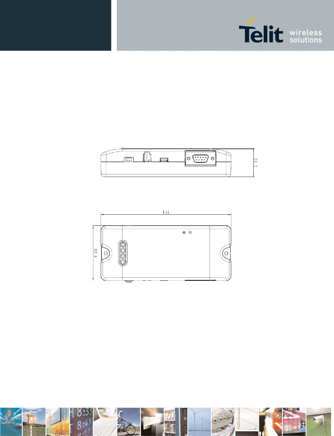
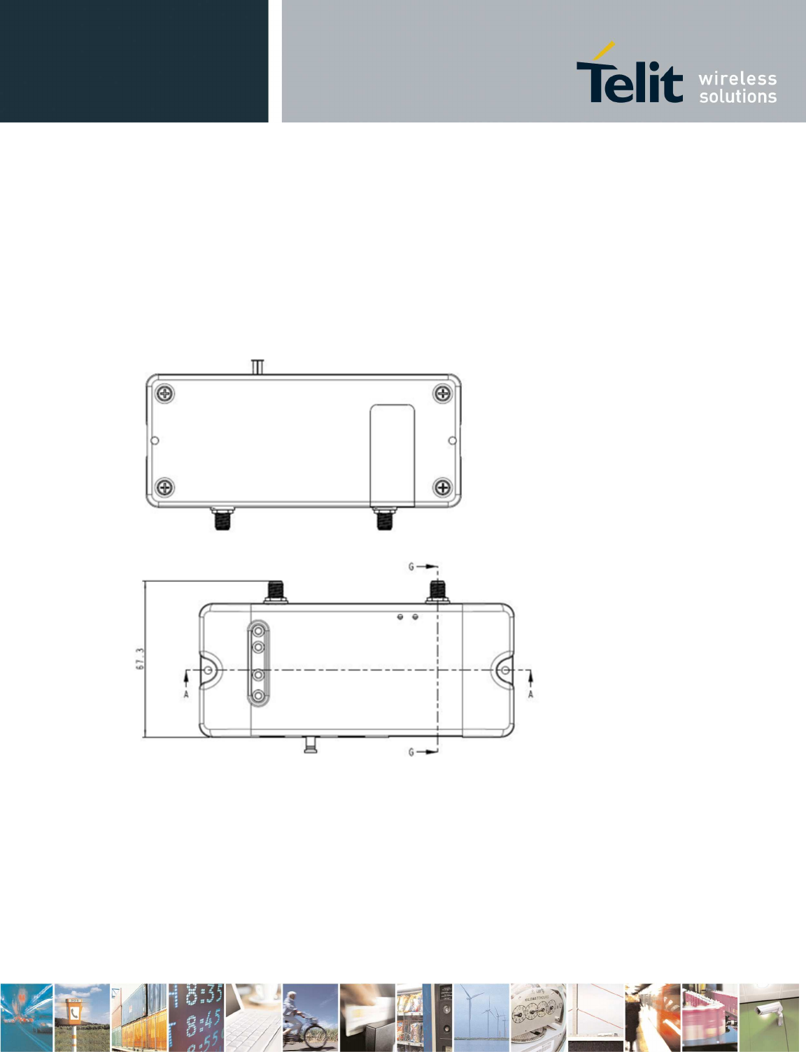
2.3 Physical Characteristics
2.3.1 Dimensions
The Telit BG864-2.4 dimensions are:
•
Length: 136 mm
•
Width: 57.6 mm
•
Thickness: 29.5 mm
Figure 3 - SWS-GW layout and dimensions
2.3.2 Environmental Characteristics
•
Operational Temperature: -20°C +60°C
•
Storage Temperature: -40°C +85°C
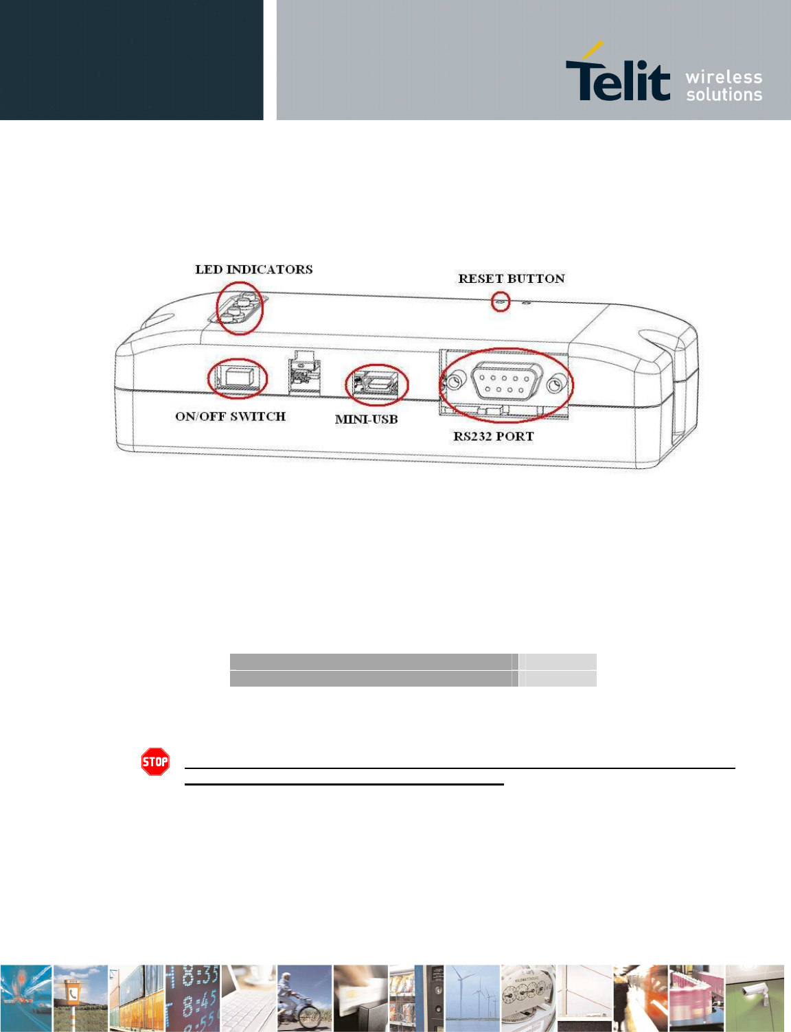
2.4 Interface Description
2.4.1 Overview
BG864-2.4 provides the following interface connectors:
•
RS232 serial interface
Reproduction forbidden without Telit Communications S.p.A. written authorization - All Rights Reserved page 10 of 73
•
Mini-USB interface
•
ON/OFF Switch Slide
Furthermore, there are four led indicators (ARM, Bluetooth, Battery Charger and SR status) and one
push button (RESET).
Figure 4 – Interface overview
2.4.2 Supply Voltage
The BG864-2.4 can be supplied by an internal rechargeable Li-Ion battery or directly by the MINI-USB
port.
Power supply input is described in the following subsection and must fulfil the following requirements:
Li-Ion Batt. Supply Voltage Range 3.4÷4.2V
Mini USB Supply Voltage Range 4.5÷5.5V
Table 1 – Supply Voltage
Danger – Operating voltage range must never be exceeded; care must be taken
in order to fulfill Min/Max voltage requirements.
2.4.3 Battery source
Power is supplied by an internal rechargeable Li-Ion battery.
Battery voltage range is 3.4 ÷ 4.2V.
If the Gateway is connected via the Mini-USB to an external PC (or power supply) then the battery will
be automatically recharged by means of integrated battery charger circuitry.
Reproduction forbidden without Telit Communications S.p.A. written authorization - All Rights Reserved page 11 of 73
The battery capacity should be sized on the customer’s application and battery life requirements.
Warning – Do not charge the Li-Ion battery out of temperature range of
0
÷45°C
.
Battery connector must be Molex 87439-0200 or compatible.
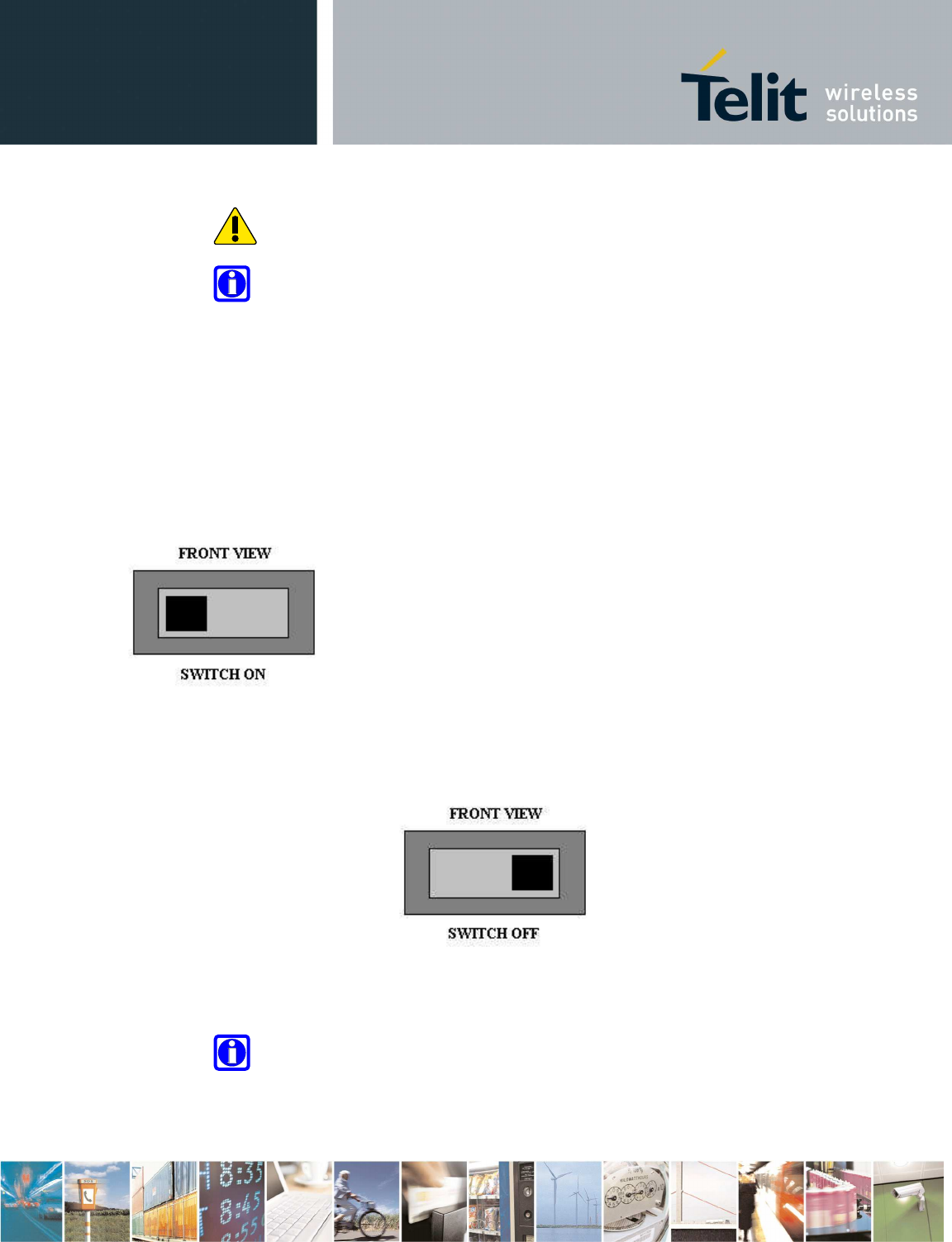
2.4.4 Switching the BG864-2.4 ON and OFF
The switch on/off slide button is used to turn ON or OFF the gateway
.
2.4.4.1 Switching ON Procedure
The BG864-2.4 switches on when slide switch is moved on the left.
BG864-2.4 operating system is operational after about 20 seconds from the power-on.
2.4.4.2 Switching OFF
The BG864-2.4 switches off when slide switch is moved on the right.
The BG864-2.4 can be switched off either by disconnecting the power supply from the MINI-USB port
and the battery or by software command.
It is suitable a software switch-off command before disconnect the power supply.
Note- When the slide switch is in OFF position and the battery is
connected, battery charge continues to function if BG864-2.4 is connect to
an external supply from the MINI-USB port
Reproduction forbidden without Telit Communications S.p.A. written authorization - All Rights Reserved page 12 of 73
2.4.5 Antenna
In BG864-2.4 there are two internal antennas, one for Bluetooth and one for the Short Range
technology.
2.4.5.1 Bluetooth Antenna specifications
The Bluetooth antenna for BG864-2.4 has the following specifications:
Bluetooth ANTENNA SPECIFICATIONS
Frequency Range
2.4 GHz
Bandwidth
2.4 – 2.5 GHz
Peak
Gain
2.2 dBi
Average Gain
1.9 dBi
Impeda
nce
50 ohm
Peak Efficiency
74%
Average Efficiency
72%
VSWR
< 2:1
Table 2 – Bluetooth Antenna specifications
2.4.5.2 Short Range Antenna Specifications
The short range antenna for BG864-2.4 has the following specifications:
Short Range ANTENNA SPECIFICATIONS
Frequency Range
2.4 GHz
Bandwidth
2.4 – 2.5 GHz
Peak
Gain
2.2 dBi
Average Gain
1.9 dBi
Impedance
50 ohm
Peak Efficiency
74%
Average Efficiency
72%
VSWR
< 2:1
Table 3 – Short Range Antenna specifications
2.4.6 Serial Port
The RS232 standard interface serves to connect a PC, Data Terminal Equipment (DTE) or an
application, wich acts as host controller for the BG864-2.4 with all its functions.
Serial port connects directly the host controller with the UART-Debug of the ARM chip inside BG864-
2.4.
RS232 level translator is present on board.
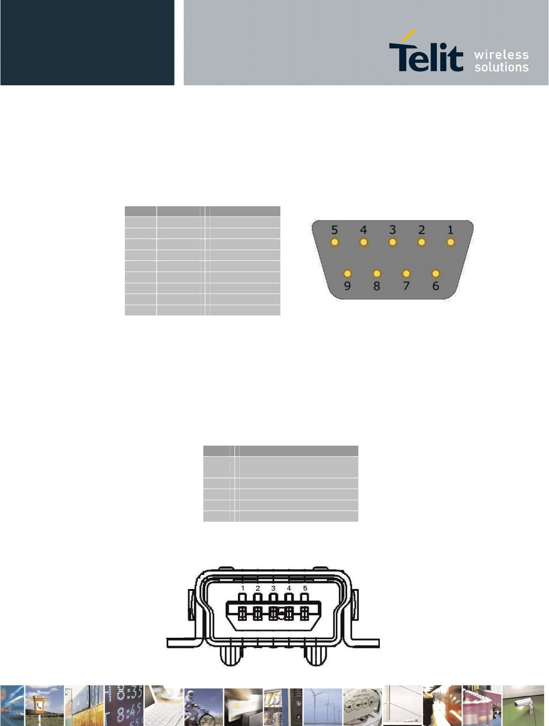
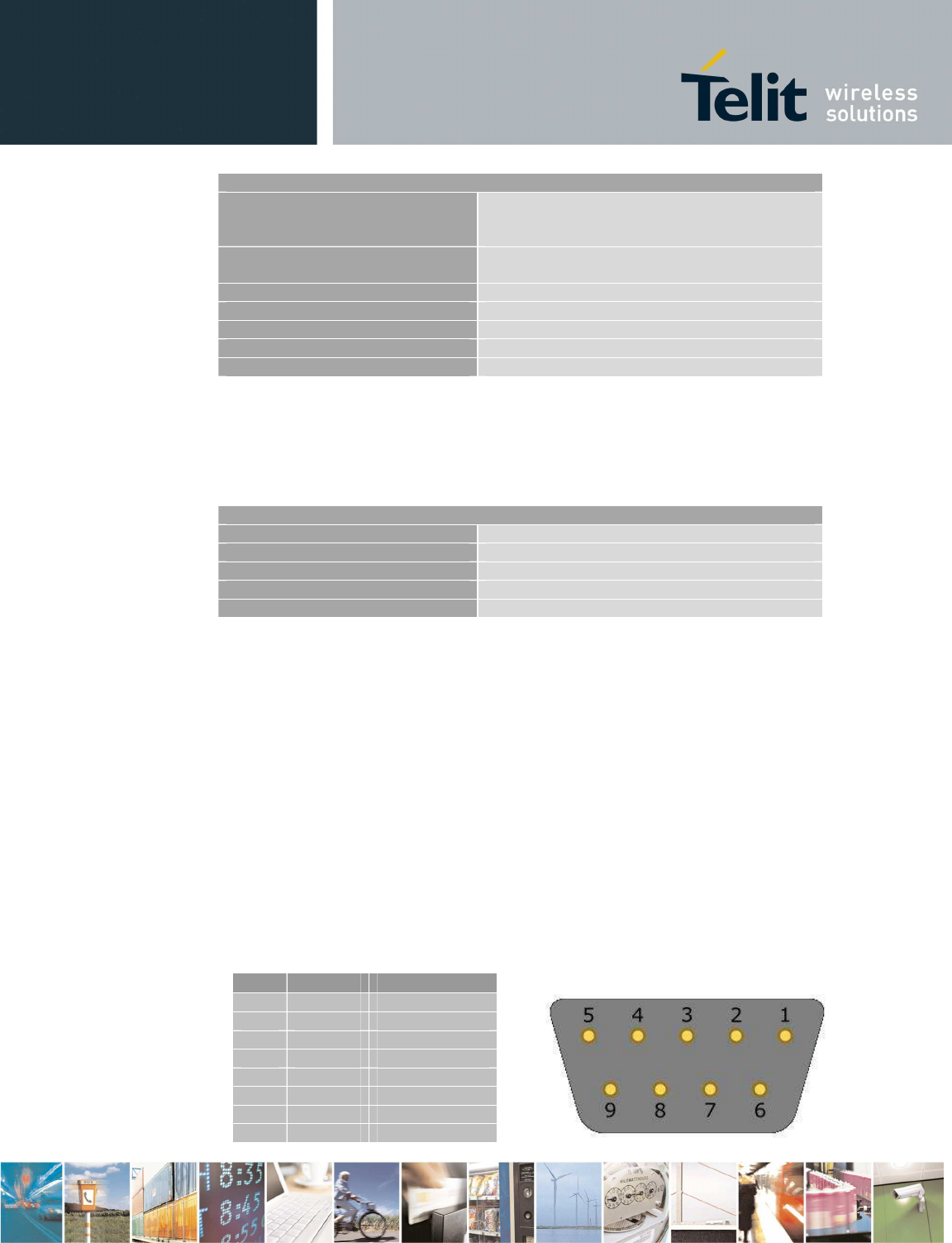
2.4.6.1 RS232 standard interface connector
The connector mounted in the BG864-2.4 is a standard RS232 Sub-D 9pin female with the following
characteristics:
Baud rate from 300 to 115.200 bit/s
Autobauding (300 to 38.400 bit/s)
Pin-out (refers to DTE side):
PIN
Signal
Description
1 - NC
2 RXD RX Output
3 TXD TX Input
4 - NC
5 GND GROUND
6 - NC
7 - NC
8 - NC
9 - NC
Table 3 – serial port pin-out
To connect to a host controller, a pin-to-pin 9pin cable with D9 type connectors on both sides is
needed (1 male & 1 female). Shielding of this cable is recommended and its length shall not exceed
3 m.
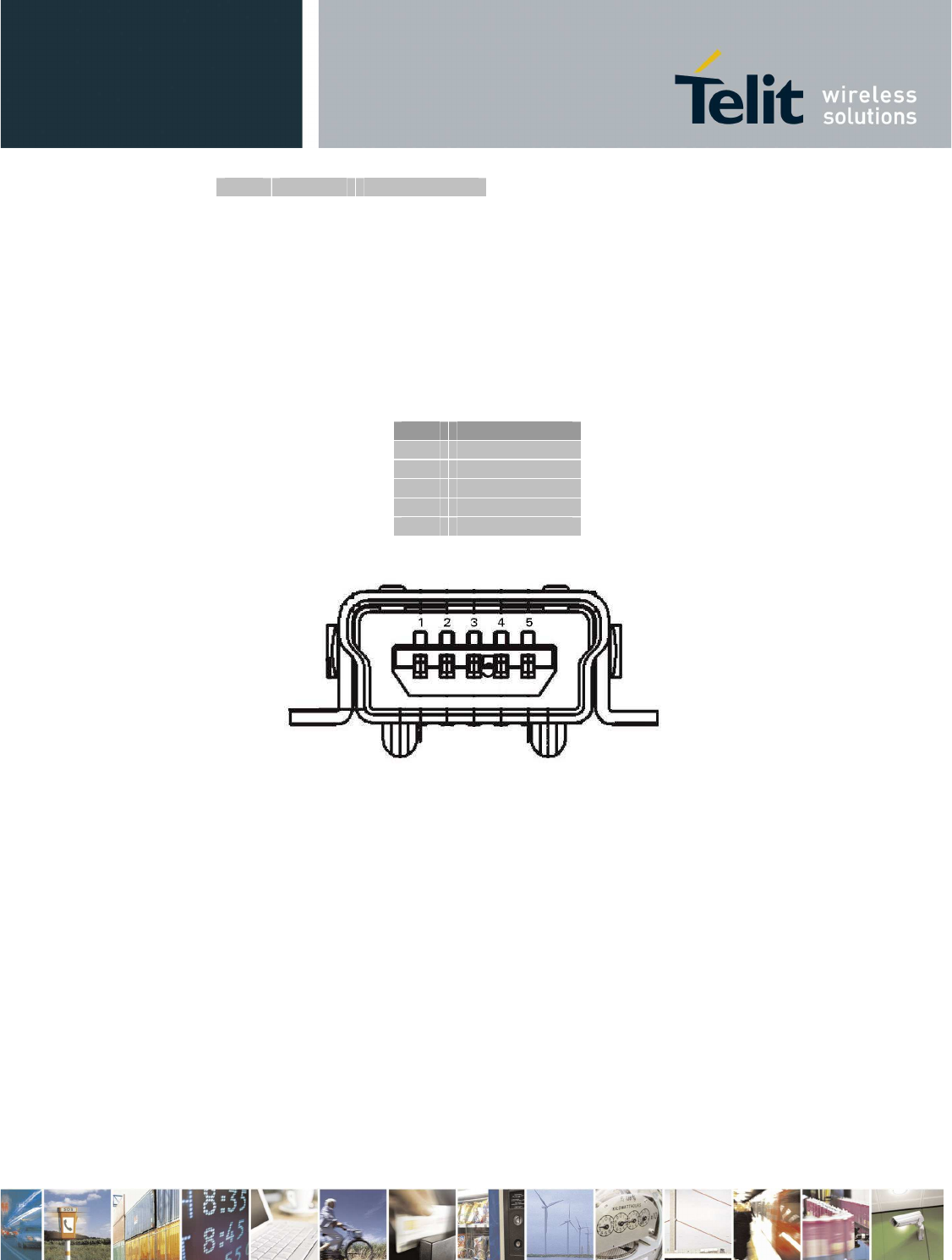
2.4.7 Mini USB type connector
Pin-out of Mini-USB connector is shown in the following table:
PIN
Signal
1 USBCNX /
Charger Power Supply
2 DDM
3 DDP
4 -
5 GND
Table 4 – Mini USB pin-out
(FRONT VIEW)
Figure 5 - Mini-USB connector front view
Reproduction forbidden without Telit Communications S.p.A. written authorization - All Rights Reserved page 14 of 73
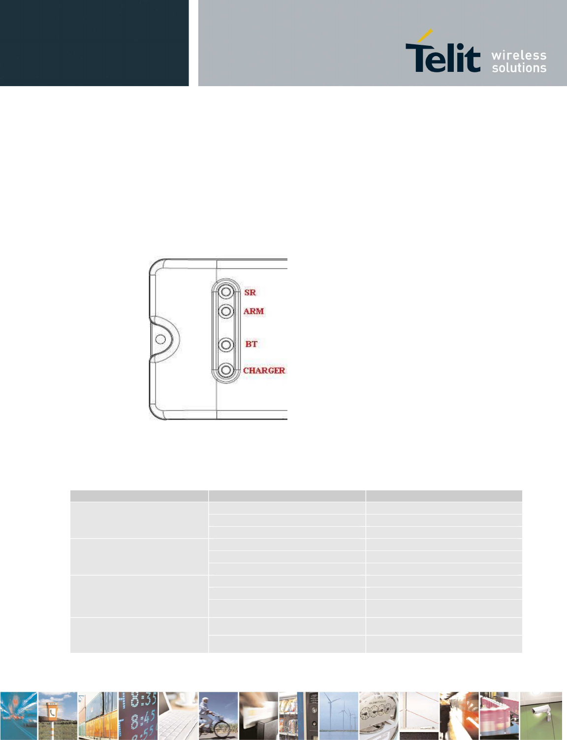
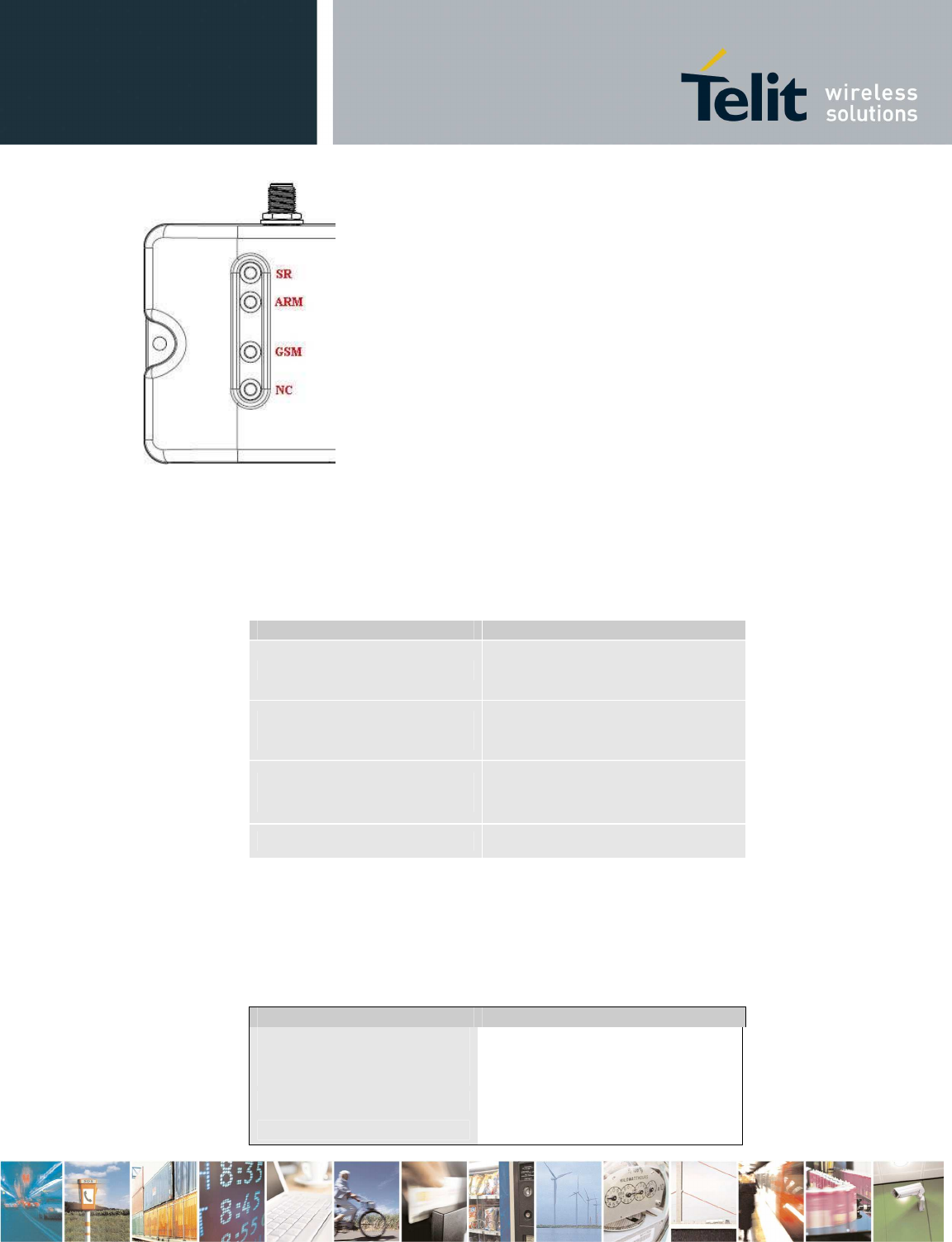
2.4.8 LEDindicators
The BG864-2.4 has four led indicators:
1. Bluetooth status,
2. ARM status,
3. SR status
4. charger status.
Figure 6 - LED indicators
2.4.8.1 Bluetooth LED indicator
The follow table shows information on the status of the four led indicators:
LED ID LED STATUS DEVICE STATUS
SR Permanently OFF OFF
Blinking Comm. Session
Permanently ON Wake-up Session
ARM Permanently OFF OFF/Stand-by
Blinking Operating
Permanently ON Boot State
BT
Permanently OFF OFF
Blinking Connected
Permanently ON Network Scan
BATT. CHARG. Permanently ON Battery charging
Permanently OFF Charge Complete
TABLE 5 – LED indicators
Reproduction forbidden without Telit Communications S.p.A. written authorization - All Rights Reserved page 15 of 73
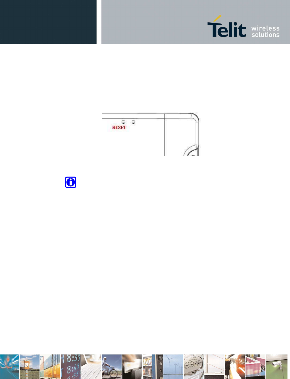
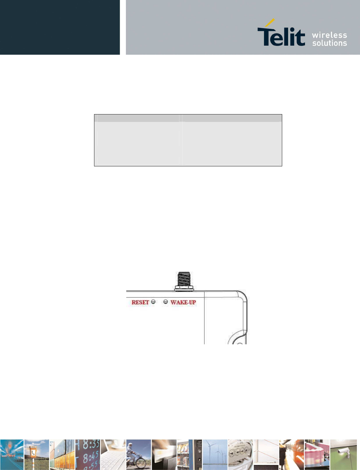
2.4.9 Push Button
In the surface of the BG864-2.4 box there is one hole to allowing with a sharp object to push the
reset button inside.
Reset Button is connected to the reset signal of the ARM processor. Pushing this button force the
reset and make the BOOT of the processor.
Figure 7 - Push Buttons
Note- The second hole near reset button’s hole is unused
Reproduction forbidden without Telit Communications S.p.A. written authorization - All Rights Reserved page 16 of 73
3 Configuration 2 (GG864-2.4)
JTAG
LED 1
UART
L.R. Ext.
Antenna
ZB Ext.
Antenna
UART
Mini-USB
Type B
USB
device
AP DATA
RS232
JTAG
USB host
1.8V 3.1V
ARM9
1.8V
MEMORY
3.8V
GC/UC
864
RF
RF
SIM CARD
ZE60
3.1V
UART
#6 GPIO
5 - 15V
Power
Supply
3.1V 1.8V
#3 GPIO
+
No-Recharg.
Batt.
LED 2
TRANSC.
RTC
RESET
button
LED 4
WAKEUP
button
3.8V
PIC
#3 GPIO
3.1V
#3 GPIO
5.0V_B 5.0V_B
Config. 2
Figure 8 Configuration 2 Block Diagram
3.1 Main Building Blocks
•
ARM9 ATMEL AT91SAM9260
•
Memories (Flash and RAM)
•
ZE60
•
GSM module Unified FF (GC864)
•
SMA connectors for External antennas:
o
GSM
o
ZE60
•
external I/F connectors
o
Power supply
o
RS232

Reproduction forbidden without Telit Communications S.p.A. written authorization - All Rights Reserved page 17 of 73
o
SIM card holder
o
Mini-USB
•
Status leds for:
o
GSM
o
ZE60
o
ARM
•
Box
•
Reset button and Wake-Up button
•
Power supply voltage 5-15V
•
Operational Temperature: [-20°C +70°C]
•
Storage Temperature: [-40°C- +80°C]
3.2 Main Building Blocks features
•
GC864 GSM module
o
Quad-band EGSM 850/900/1800/1900 MHz
o
Control via AT commands according to GSM 07.05, 07.07 and Telit enhancements
o
Serial Port multiplexer GSM 7.10
o
SIMM access profile
o
TCP/IP stack access via AT commands
o
Supply voltage range: 3.22-4.5V DC
o
Dimensions: 30x36.2x3.2 mm
o
Weight: 6.1 grams
o
RoHS compliant
o
Extended temperature range
- -40°C to 85°C (operational)
- -40°C to 85°C (storage)
o
Sensitivity:
- -107 dBm (typ.) @ 850/900 MHz
- -106 dBm (typ.) @ 1800/1900 MHz
o
Power consumption (typ.)
- Power off: <26 uA
- Idle(registered, power saving): 2.6 mA
- Dedicated mode: 200 mA
- GPRS cl.10: 370 mA
o
Output power
- Class 4 [2W] @ 850/900 MHz
- Class 1 [1W] @ 1800/1900 MHz
Reproduction forbidden without Telit Communications S.p.A. written authorization - All Rights Reserved page 18 of 73
3.3 Physical Characteristics
3.3.1 Dimensions
The Telit GG864-2.4 dimensions are:
•
Housing Length: 136 mm
•
Overall Length: 136 mm
•
Width: 57,6 mm
•
Thickness: 29,5 mm
Figure 9 - SWS-GW layout and dimensions
Reproduction forbidden without Telit Communications S.p.A. written authorization - All Rights Reserved page 19 of 73
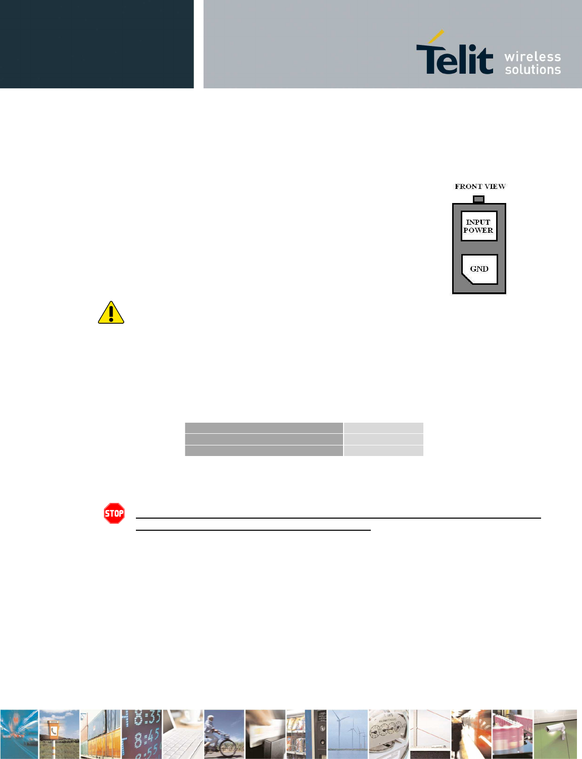
3.4 Interface Description
3.4.1 Power connector
The power connector on the left side of the terminal is a Molex 2-pins connector (part no.: 43045-
0210).
Pin description:
•
GND = Ground reference
•
Input Power = 5 - 15 VDC
Warning - Power Cable connecting the the power source to the Gateway shall
not exceed 3 meters lenght
3.4.2 Supply Voltage
The external power supply must be connected to power supply input as described in the following
subsection and must fulfil the following requirements:
Nominal Supply Voltage
12 volts
Min Supply Voltage
5 volts
Max supply Voltage
15 volts
Table 5 – Supply Voltage
Danger – Operating voltage range must never be exceeded; care must be taken
in order to fulfill Min/Max voltage requirements.
3.4.3 Battery source
The external power supply could be sourced by an external no rechargeable battery.
Battery voltage range is 5 – 15V.
The battery capacity should be dimensioned on the customer’s application and battery life
requirements.
Reproduction forbidden without Telit Communications S.p.A. written authorization - All Rights Reserved page 20 of 73
3.4.4 Switching the GG864-2.4 ON and OFF
3.4.4.1 Switching ON
The GG864-2.4 switches on automatically each time the power supply is connected the first time or re-
connected.
Note- When the power supply cable is disconnected, it is recommended to
wait approximately 5 seconds before applying the power again.
3.4.4.2 Switching OFF
The GG864-2.4 can be switched off either by disconnecting the power supply or by software
command.
It is suitable a software switch-off command before disconnect the power supply cable.
Warning – Please note that hardware power off should be done only after
a proper GSM logoff. Any GSM device is request to issue a “detach”
request at turning off.
3.4.5 Antenna
3.4.5.1 Antenna Output
Warning – BEFORE connecting the GG864-2.4 to a power supply source, suitable
antennas shall be connected and properly installed.
The antenna has to be installed with care to avoid any interference with other electronic devices
and has to guarantee a minimum distance from the body (20 cm). in case this requirement cannot
be satisfied, the system integrator has to assess the final product against the SAR regulation.
For a good efficiency of the antenna and a minimum interference with other electronic systems, a
space of min. 40 cm around the radiating part should be left free of electrically conducting materials.
The less distance and the fewer obstacles between the SWS-GW antenna and the antenna of the
GSM/GPRS network base station, the less power is radiated by the gateway and the better signal
quality is achieved.
3.4.5.2 Antenna Connectors
The GG864-2.4 includes two SMA bulkhead female, class 4 (2W) co-axial connectors for the two
external antennas.
3.4.5.3 GSM Antenna Requirements
The GSM antenna for GG864-2.4 device shall fulfill the following requirements
:
Reproduction forbidden without Telit Communications S.p.A. written authorization - All Rights Reserved page 21 of 73
GSM ANTENNA REQUIREMENTS
Frequency Range
Standard Dual Band GSM/DCS frequency
range or Standard Quad Band GSM/DCS/OCS
frequency range if used for all four bands
Bandwidth
70 MHz in GSM850, 80 MHz in GSM &
170MHz in DCS & 140 MHz PCS band
Gain
< 3 dBi
Impedance
50 ohm
Input power
> 2 W peak power
VSWR absolute max
<= 10:1
VSWR recommended
<= 2:1
Table 6 – GSM Antenna requirements
3.4.5.4 Short Range Antenna Requirements
The short range antenna for GG864-2.4device shall fulfill the following requirements:
Short Ra
nge ANTENNA REQUIREMENTS
Frequency Range
2.4 GHz
Bandwidth
2.30 – 2.50 GHz
Gain
< 4 dBi
Impedance
50 ohm
VSWR recomme
nded
<= 1.5:1
Table 7 – Short Range Antenna requirements
3.4.6 Serial Port
The RS232 standard interface serves to connect a PC, Data Terminal Equipment (DTE) or an
application, witch acts as host controller of the SWS-GW with all its functions.
Serial port connects directly the host controller with the UART-Debug of the ARM chip of SWS-GW.
RS232 level translator is present on board.
3.4.6.1 RS232 standard interface connector
The connector mounted in the SWS-GW is a standard RS232 Sub-D 9pin female with these
characteristics:
Baud rate from 300 to 115.200 bit/s
Autobauding (300 to 38.400 bit/s)
Pin-out (refers to DTE side):
PIN Signal Description
1 - NC
2 RXD RX Output
3 TXD TX Input
4 - NC
5 GND GROUND
6 - NC
7 - NC
8 - NC
9 - NC
Table 8 – serial port pin-out
To connect to a host controller, a pin-to-pin 9pin cable with D9 type connectors on both sides is
needed (1 male & 1 female). Shielding of this cable is recommended and its length shall not exceed
3 m.
3.4.7 Mini USB type connector
Pin-out of Mini-USB connector is shown in the following table:
PIN
Signal
1 USBCNX
2 DDM
3 DDP
4 -
5 GND
Table 9 – Mini USB pin-out
3.4.8 LED indicators
The GG864-2.4 has three led indicators:
1. GSM status
2. ARM status
3. SR status (fourth led indicator is not connected in this configuration).
(FRONT VIEW)
Figure 10 - Mini-USB connector front view
Reproduction forbidden without Telit Communications S.p.A. written authorization - All Rights Reserved page 23 of 73
Figure 11 - LED indicators
3.4.8.1 GSM LED indicator
The red LED shows information on the network service availability and call status.
LED STATUS DEVICE STATUS
permanently on a call is active
fast interrupt sequence
(period 0,5s, Ton 1s) Net search / Not
registered / turning off
slow interrupt sequence
(period 0,3s, Ton 3s) Registered full service
permanently off device off
TABLE 10 – GSM LED indicator
3.4.8.2 ARM LED indicator
The red LED shows information on the ARM status:
LED STATUS DEVICE STATUS
Permanently OFF
OFF/Stand-by
Blinking Operating
Permanently ON Boot State
Reproduction forbidden without Telit Communications S.p.A. written authorization - All Rights Reserved page 24 of 73
TABLE 11 – ARM LED indicator
3.4.8.3 Short Range LED indicator
The red LED shows information on the network service availability and call status.
LED STATUS
DEVICE STATUS
Permanently OFF
Blinking OFF
Comm. Session
Permanently ON Wake-up Session
TABLE 12 – SR LED indicator
3.4.9 Push Buttons
In the box of GG864-2.4 there are two holes to push with a sharp object the two buttons inside:
•
Reset Button: is connected to the reset signal of the ARM processor. Pushing this button
force the reset and make the BOOT of the processor.
•
Wake-Up Button: is connected to the wake-up signals of the ARM processor. Pushing this
button wake-up the processor from a power mode state.
Figure 12 - Push Buttons

Reproduction forbidden without Telit Communications S.p.A. written authorization - All Rights Reserved page 25 of 73
4 SW Specification
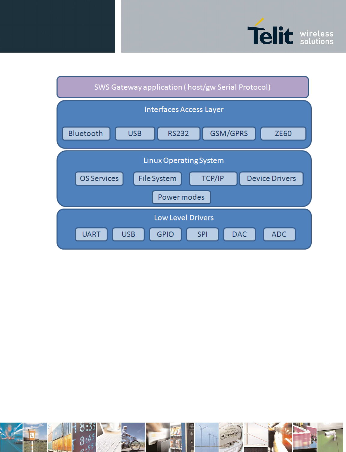
4.1.1 SW architecture
In the following picture is depicted SW architecture of Gateway in both configuration1 (BG864-2.4) and
configuration 2 (GG864-2.4).
Telit provides Linux Operating system with all low level drivers needed in the SWS gateway:
•
GPIO
•
Serial
•
USB device
And provides access for the main peripheral:
•
Bluetooth
It is provided all sw to initialize and setup Bluetooth communication and access to the Bluetooth
interface as a serial port where it is possible to send and receive data (SPP profile).
•
GSM/GPRS
Communication with GSM/GPRS is provided through the serial port where it is possible send and
receive data.
•
USB
•
ZE60
And to manage power modes.
SWS Gateway application is a customization of Gateway application with the scope of export the
serial protocol Interface to communicate with the external host.
It:
•
Manages the gateway
•
Route messages between peripherals
•
Wake up and power up the peripherals at preprogrammed intervals
Reproduction forbidden without Telit Communications S.p.A. written authorization - All Rights Reserved page 26 of 73
Figure 13 Gateway SW architecture
For detailed specification of the communication protocol see next paragraphs.
4.1.1.1 SWS Gateway Application (Configuration 1 –no GSM)
In this configuration two operating modes are possible:
1. Autonomous gateway
In this mode gateway is in standalone mode, without any external devices connected to it and
communicates only via radio with DXT in the SR network, collecting data sent by each DXT in
a log file stored in flash.
Upload of log data files will be possible through specific command on serial protocol to retrieve
the file (see Get Log file).
Format of log files, naming convention and upload process have to be agreed with Alciom.
2. Slave mode
In slave mode, gateway is connected to other device that acts as a master and controls the
operations of the gateway.
Other devices can be:
•
Fixed PC by USB connection

Reproduction forbidden without Telit Communications S.p.A. written authorization - All Rights Reserved page 27 of 73
•
Mobile devices, as PDA, phone, field equipment, through Bluetooth connection or RS232
serial connection.
In slave mode gateway supports communication protocol between host and gateway that has to
be the same through all the interfaces:
•
USB
•
RS232
•
Bluetooth
•
GSM/GPRS* (by socket connection- see sws gateway application conf 2)
As all the interfaces can be seen as serial interfaces a serial protocol will be developed. All the
interfaces will be available at the same time but communication will be with one of them at a time.
A specific command will be developed to set the communication mode and to switch to another
(see Set Gateway Mode command).
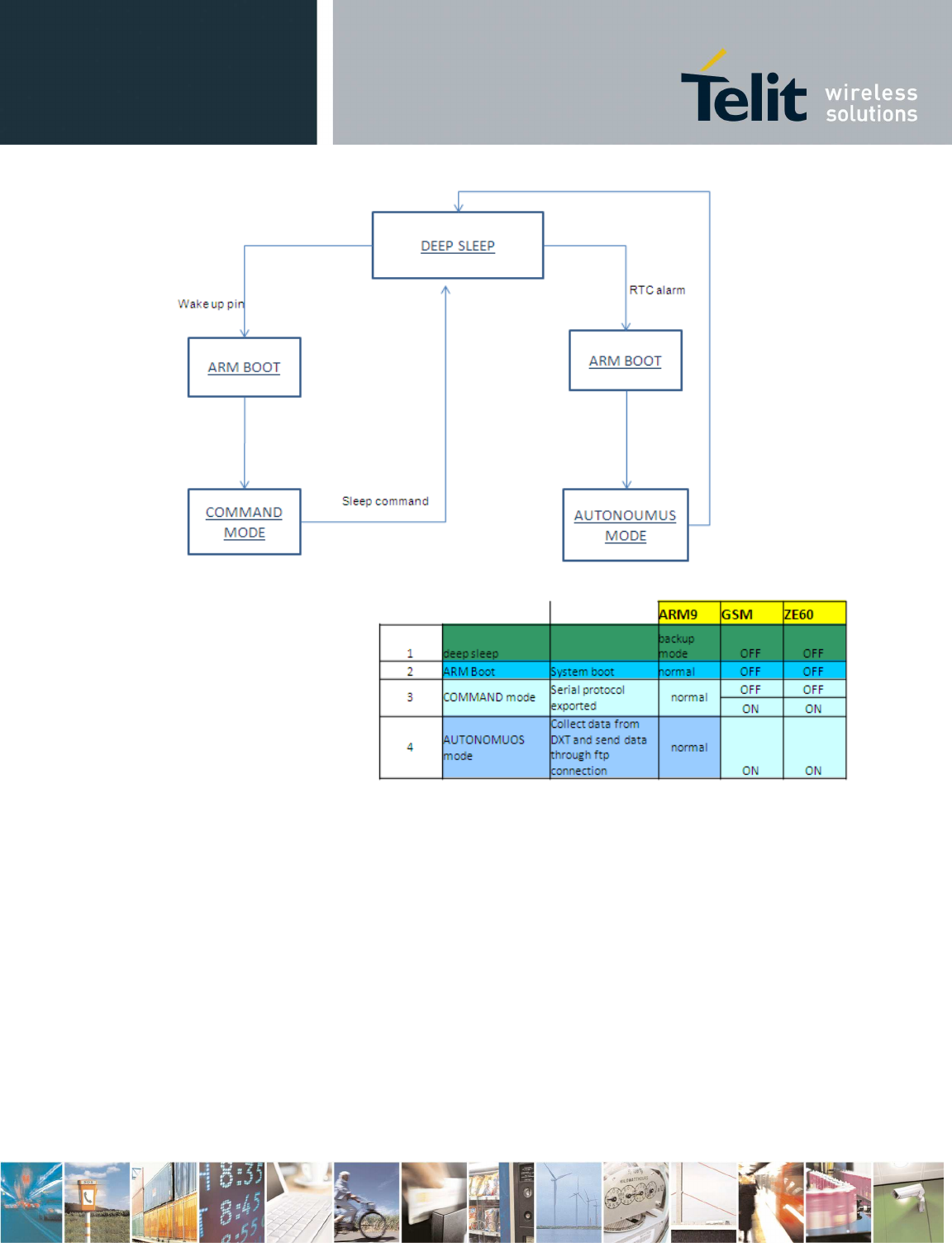
4.1.1.2 SWS Gateway Application (Configuration 2 – GSM)
In this configuration two operating modes are possible:
1. Autonomous gateway(
In this mode gateway is in standalone mode, without any external devices connected to it and
communicates only via radio with DXT in the SR network, collecting data sent by each DXT in a log
file stored in flash, and sending it at preprogrammed interval (once a day) through GPRS network to
an FTP server.
2. Controlled mode
In this mode, gateway is always connected to GSM/GPRS network , or always connected via USB or
RS232 to the server and wait commands from it.
In this mode all the command /answer should follow the serial protocol described in next paragraph.
If GPRS/GSM connection is active, same protocol as described in next paragraph will be available
through socket connection.
.
Reproduction forbidden without Telit Communications S.p.A. written authorization - All Rights Reserved page 28 of 73
Sws Gateway
Short Range Functionalities
Interface
Data Interface
Control Interface
link
Host
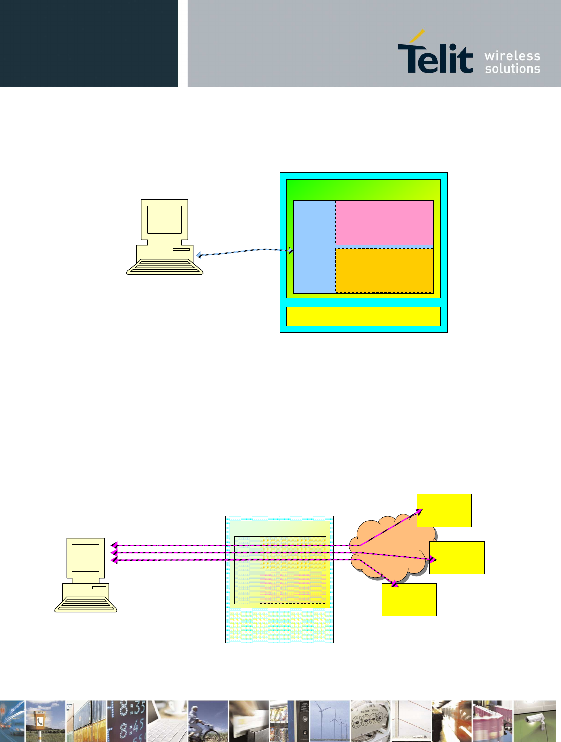
4.2 Host/gateway serial protocol
The Host interacts with the SWS GW Application through a serial interface
This serial interface is internally split into two interfaces:
1. Control (or management) Interface. This interface receives commands from Host and sends
back information/responses.
2. Data Interface, that allows direct communication with DXT nodes joined to the SR network.
Control and Data Interfaces are mutually exclusive, they can be used one at a time.
4.2.1.1 Data-mode
If the data-mode is used, SWS Gateway is completely transparent. Data messages flow in both
directions as a raw bit stream.
Figure 7 – Gateway in data mode
DXT
SWS Gateway
Short Range
Functionalities
Data Interface
Control
Interface
Host
DXT
Short Range
network
DXT
The way data messages are used is totally user dependent. From a logical point of view the
responsible for data managing are applications running on Host and each DXT connected to the
gateway.
Figure 8 – Data Mode: data flow at application layer
4.2.1.2 Command-mode
If command-mode is used, the Host may send specific commands to SWS gateway in order to
configure it.
4.3 Control Interface
Once SWS GW Application has been started, the Control Interface will be available on the serial
interface ( it can be RS232, USB or Bluetooth)
The Control Interface receives from the Host the serial packets, converts them to internal control
messages and sends the responses to the Host.
All frame formats in this clause are routed in the order in which they are transmitted, that is, from left to
right. For every field the left most byte is the least significant byte and the right most byte is the most
significant byte (little endian).
The serial packets shall be formatted as illustrated in Figure 9 .
Figure 9
Every packet has a START byte and a STOP byte.
4.3.1 Stuff algorithm
When using START and STOP bytes in the Message, it must be ensured that they will not be
confused with the true START and STOP. To achieve this result, an escaping technique called “stuff
Message STOP
Variable 1 Byte 1 Byte
START
Short Range
Network
SWS
Gateway
Short Range
Functionalities
Application
DXT
Application
Host
Reproduction forbidden without Telit Communications S.p.A. written authorization - All Rights Reserved page 31 of 73
algorithm” has to be used. Every time the Message field contains a byte equal to the START or the
STOP, the same byte must be preceded by a STUFF byte and incremented of an OFFSET. Every
time that in the Message field there is a byte equal to the STUFF byte it must be preceded by another
STUFF byte.
Values of START, STOP, STUFF and OFFSET bytes are shown in Table 4.1.
Name Value
START 0xab
STOP 0xcd
OFFSET 0x01
STUFF 0xef
Table 4.1
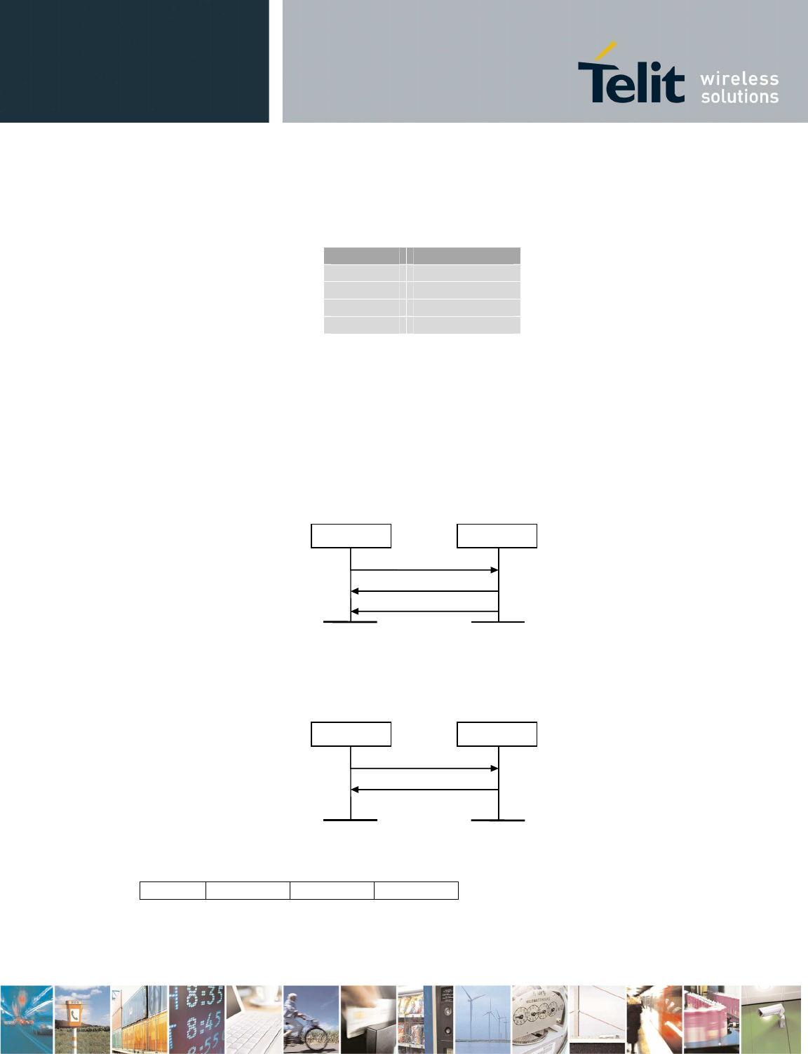
4.3.2 Message protocol
The message protocol is used by the Host to configure and to manage the SWS Gateway. It is an
acknowledged protocol, so that every time the Host sends a command to the Control Interface of the
Gateway, it will acknowledge the command with an ACK (Figure ).
Therefore there are two types of messages:
•
Command/Response messages
•
ACK messages
Gateway
Host
Command
Ack
Response
Figure 10
If the Command do not respect the protocol or if its parameters are out of range, the Control Interface
of the Gateway will send only a NACK (acknowledge with status set to ERROR) and no response.
Gateway
Host
Command
Nack
Figure 11
ACK and messages are:
2 bytes 1 byte
START Opcode Status STOP
Status message for ACK is 0x01, status message for NACK is 0x02.
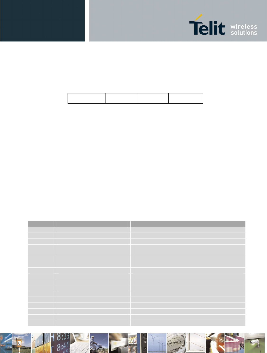
4.3.3 Command and Response messages
Command and Response messages format is shown in the Figure 42.
Figure 42
The OpCode is the code of the Command sent by the Host or the Response sent by the Gateway. The
field BitMask explains which parameters are active in the Parameters field. Note that all the
parameters are always present in the packet, so a specific Command/Response has always the same
size. If a parameter is not active, the respective value will be not modified. If a parameter is mandatory
and an invalid BitMask field has been set, command will be not executed. Default values will be
loaded by Reset command.
The field Reserved is ignored, and its value shall be set to 0xFF.
The field Parameters holds the parameters of the command. It has a specific format for every
command depending on the OpCode. Every parameter could be optional (O) or mandatory (M), if it is
optional and the parameters is not enabled the Gateway will use a default value.
Every response has a Status field. All the parameters of responses are mandatory.
Every command has a 10 minutes timeout. When timeout expires and command is not executed yet,
error response will be received.
During execution of any command (after ACK message has been received and before response is
received), only Get Status and Reboot commands can be executed; other commands or bytes on
control interface are not considered.
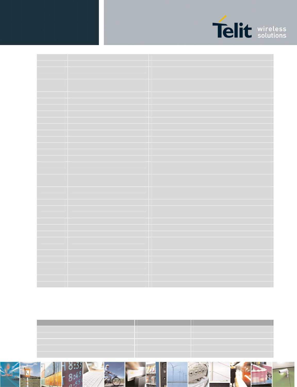
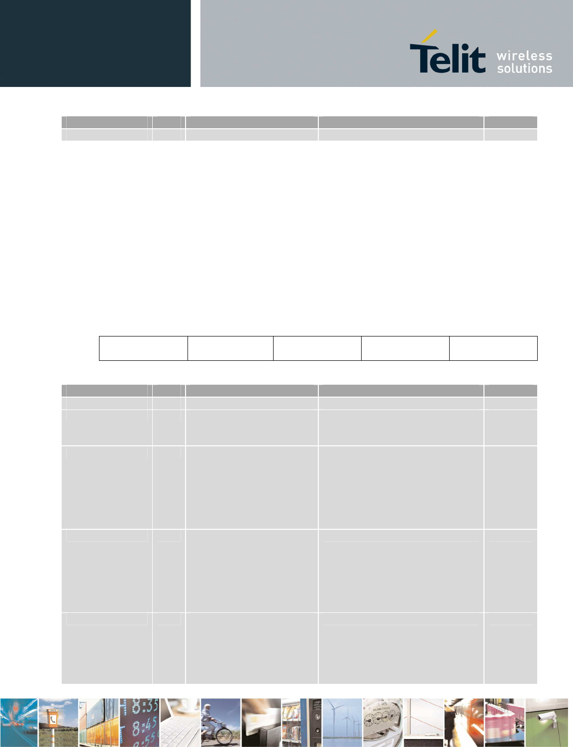
Table 4.2 shows the list of commands and responses.
OP Code Command/Response Name Description
0x0001
Set date/time
Set RTC time
0x0002 Get date/time Get RTC time
0x0003 Get serial number Get gateway serial number
0x0004 Set GW SR parameters Set radio channel, network ID, encryption word
and
wakeup s
ession timings
in the GW
0x0005 Set DXT SR parameters Set radio channel, network ID, encryption word
and
cyclic w
akeup timings
in a DXT
0x0006 Set gateway mode Choose control interface (BT/USB/UART/GSM)
0x0007 Set GSM parameters Set APN, DNS and SIM PIN
0x0008 Set BT parameters Set BT local name and PIN
0x0009 Get Battery level Get Battery level (percentage)
0x
000
A
Get hw/sw version
Get hardware/software version
0x000B Get GSM parameters Get GSM parameters
0x000C Get GW SR parameters Get SR parameters from the GW
0x000D Get DXT SR parameters Get SR parameters from a DXT
0x000E Scan for DXT Scan for active DXTs
0x000
F
Set
Auto
DXT Data
Set
parameters
of Get D
ata from DXTs when
GW
2 Bytes
OpCode BitMask Reserved
2 Bytes 1 Byte
Parameters
Variable
Reproduction forbidden without Telit Communications S.p.A. written authorization - All Rights Reserved page 33 of 73
is in autonomous mode
0x0010 Get Status Get SR/BT/GSM status
0x0011 Set data mode Set transparent communication to the local SR
module
0x0012 Set Escape sequence from
data mode Set Escape sequence from transparent
communication to the local SR module
0x0013 Get DXT Data Get DXT Data (over serial communication or FTP)
0x0014 Add DXT list Add a DXT in the list
0x0015 Get DXT list Get the DXT list
0x0016 Remove DXT list Remove a DXT from the list or clean it
0x0017 Disable SIM PIN Disable PIN SIM
0x0018 Turn off SR Turn off SR module in the GW
0x0019 Reboot Reboot gateway
0x001A Standby Put gateway in standby
0x001B Deep Sleep Put gateway in deep sleep
0x001C Turn off Turn off gateway
0x001D Reset Reset configuration and reboot GW
0x001E Get Auto Dxt Data Get parameters of Get Data from DXTs when GW
is in autonomous mode
0x001F Get Log File Get application log file (over serial communication
or FTP)
0x0020 Get BT parameters Get name and address of the local and host BT
device
0x0021 Scan for BT Scan for discoverable BT devices
0x0022 Add BT host Put BT in discoverable state and wait for pairing
with BT host
0x0023
Reset BT host
Delete pairing with BT host
0x0024 Set GPRS host parameters Set parameters for control interface on GPRS
0x0025 Set FTP parameters Set parameters of the FTP server
0x0026 Set Wakeup parameters Set date/hour of the next wake up (autonomous
mode for C2)
0x0027 Get GPRS host parameters Get parameters for control interface on GPRS
0x0028 Get FTP parameters Get parameters of the FTP server
0x0029 Get Wakeup parameters Get date/hour of the next wake up (autonomous
mode for C2)
0x002A Flash SR Flash SR through USB
0x002B Get Battery voltage Get Battery voltage and get temperature
Table 4.2
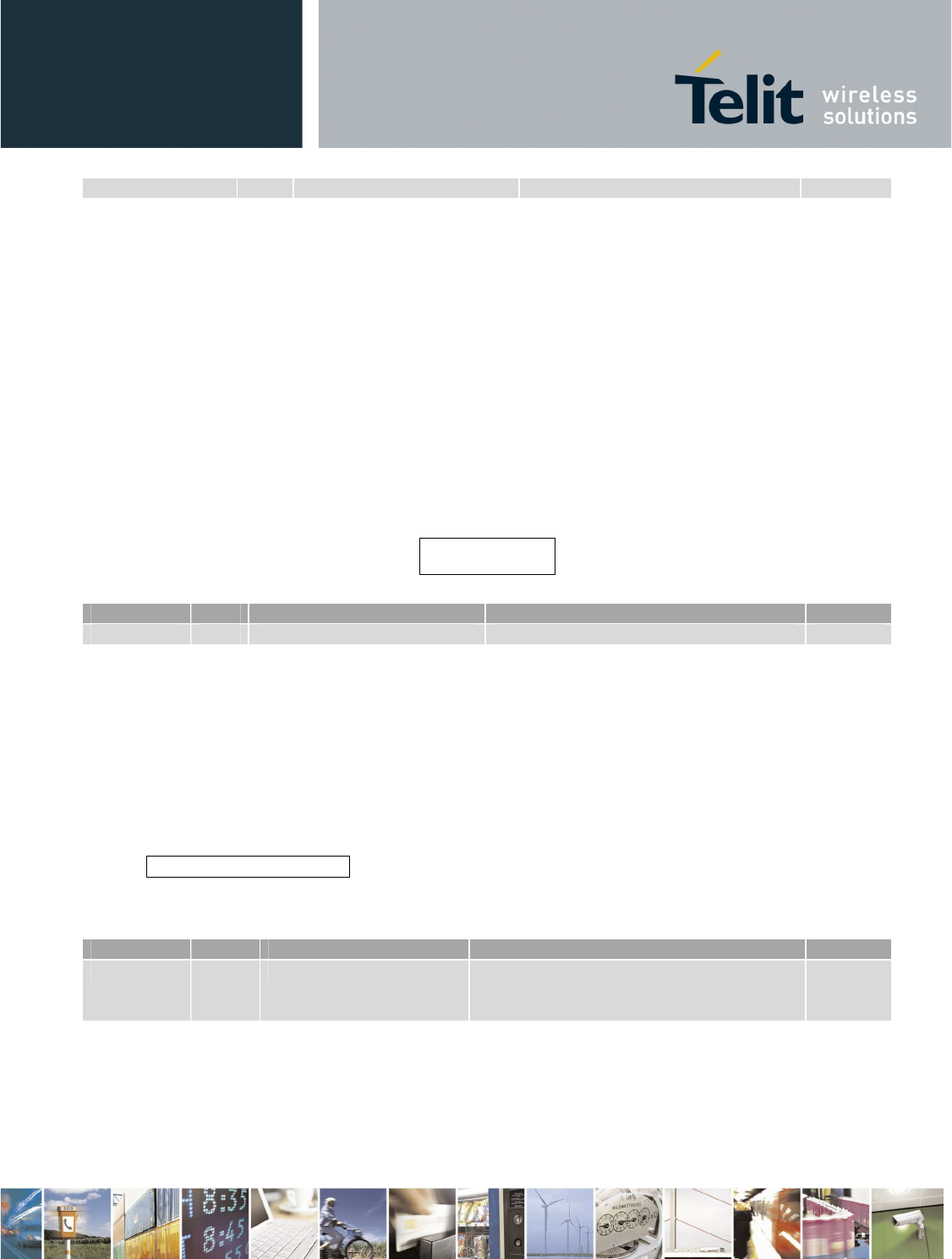
Table 4.3 shows the values of the Status codes for the responses.
Status Value Description
SUCCESS 0x0001 The command succeeded
ERROR
0x0002
Generic error
TIMEOUT 0x0003 Command timeout expired
DXT END 0x0004 Scan DXT process is complete
PASSWORD ERROR 0x0005 Wrong PIN/password
Reproduction forbidden without Telit Communications S.p.A. written authorization - All Rights Reserved page 34 of 73
SR_NOT_READY 0x0006 SR module is not ready
SIM_PIN_ALREADY_DISABLED 0x0007 PIN is already disabled
BT_END 0x0008 Scan BT process is complete
NO_RESPONSE_FROM_DXTS 0x0009 DXT has been found but does
not respond during comm
session
Table 4.3
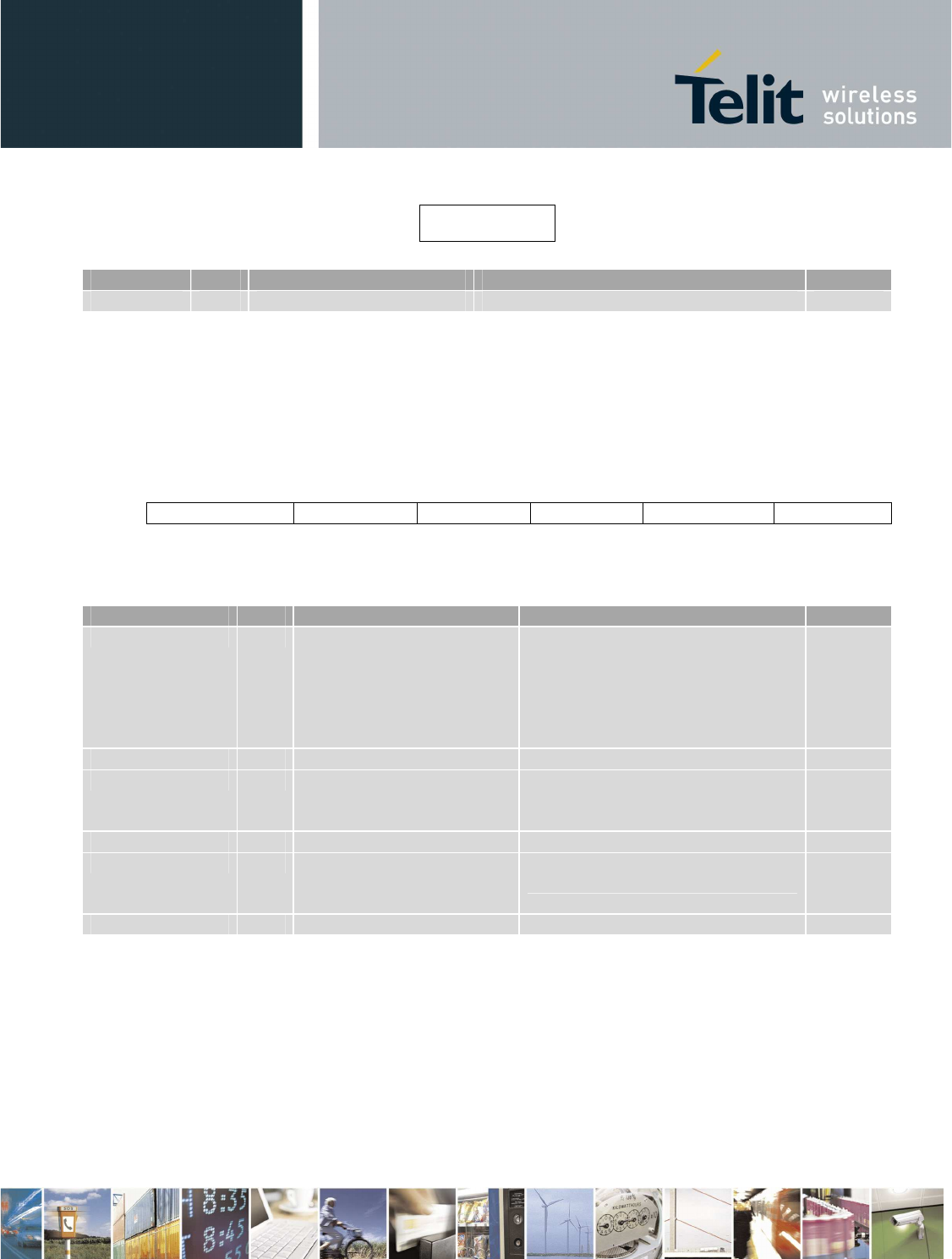
Table 2.4 shows the definition of BitMask.
Name Value Description
BIT_0 0b0000000000000001 The first parameter is enabled
BIT_1 0b0000000000000010 The second parameter is enabled
BIT_2 0b0000000000000100 The third parameter is enabled
BIT_3 0b0000000000001000 The fourth parameter is enabled
BIT_4 0b0000000000010000 The fifth parameter is enabled
BIT_5 0b0000000000100000 The sixth parameter is enabled
BIT_6 0b0000000001000000 The seventh parameter is enabled
BIT_7 0b0000000010000000 The eighth parameter is enabled
BIT_8 0b0000000100000000 The ninth parameter is enabled
BIT_9 0b0000001000000000 The tenth parameter is enabled
BIT_10 0b0000010000000000 The eleventh parameter is enabled
BIT_11
0b00001000
00000000
The twelfth parameter
is enabled
BIT_12 0b0001000000000000 The thirteenth parameter is enabled
BIT_13 0b0010000000000000 The fourteenth parameter is enabled
BIT_14 0b0100000000000000 The fifteenth parameter is enabled
BIT
_15
0b10000000
00000000
The eighteenth parameter
is enabled
Table 4.4

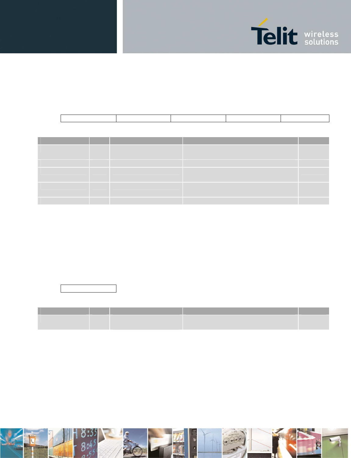
4.3.4 Commands/response description
4.3.4.1 Set Date/Time
Set RTC time.
OPCODE: 0x0001
field parameters is:
Day Month Year Hour Minutes
All the parameters are mandatory.
Field Size(bytes) Valid Range Description Default
Day 1 1-31 Day of the month N/A
Month 1 1-12 Month of the year N/A
Year 1 10-37 Year since 2000 N/A
Hour 1 0-23 Hour since midnight N/A
Minutes 1 0-59 Minutes after the hour N/A
When gateway is starting and RTC date is reset, default date is 1/1/2010 00:00. If a new date is set
and this is more recent than the old one, wakeup date for C2 configuration is automatically updated.
In C1 configuration, date is reset to default when gateway is turned off.
Set Date/Time Response
Field size Valid Range Description Default
Status 2 0x0001-0x0003 Result of the command N/A
4.3.4.2 Get Date/Time
Get RTC time.
OPCODE: 0x0002
field parameters is:
No parameter
Get Date/Time Response
Status
Status
D
ay
Month
Year
Hour
Minutes
Field size Valid Range Description Default
Status
2
0x0001
-
0x000
3
Res
ult of the command
N/A
Day 1 1-31 Day of the month N/A
Month 1 1-12 Month of the year N/A
Year 1 10-255 Year since 2000 N/A
Hour 1 0-23 Hour since midnight N/A
Minutes 1 0-59 Minutes after the hour N/A
4.3.4.3 Get Serial Number
Get Gateway serial number.
OPCODE: 0x0003
Parameter field=NULL
Get Serial Number Response
Field
size
Valid Range
Description
Default
Status 2 0x0001-0x0003 Result of the command N/A
S/N 12 String Serial number of GW N/A
4.3.4.4 Set GW SR parameters
Set SR parameters in the GW.
OPCODE:0x0004
field parameters is:
channel
Network
ID Old
Encryption
key
New
Encryption
key
Wakeup
session
duration
Comm
session
duration
Comm slot
duration
If a new encryption has to be set, old and new encryption keys are mandatory.
Parameters are set if SR module is not in wakeup session, comm session or comm slot.
Field size Valid Range Description Default
S/N
Status
channel
1
0x0
B
-
0x
1A
RF channel for SR network
0x0
B
Network ID 2 0x0000-0xFFFF Network ID for the SR network 0x1234
Old key 16 Any value Current Encryption word All 0x00
New key 16 Any value New Encryption word to be set N/A
Wakeup
session
duration
1 1-254 Wakeup session duration in sec 29
Comm session
duration 1 0-255 Comm session duration in sec 120
Comm slot
duration 1 0-255 Comm slot duration in sec 15
Set GW SR parameters response
Field size Valid Range Description Default
Status 2 0x0001-0x0003 or
0x0005-0x0006 Result of the command N/A
4.3.4.5 Set DXT SR parameters
Set SR parameters in a DXT.
OPCODE:0x0005
field parameters is:
Address
channel
Network
ID Old
Encryption
key
New
Encryption
key
Fast period
Slow
period
MAC address parameter is always mandatory.
If a new encryption has to be set, old and new encryption keys are mandatory.
If the SR module in the gateway is off or in idle, it performs a wakeup session and then starts a comm
slot with the DXT. If the SR module in the gateway is in comm session, scan is not performed. Comm
slot will be ended after settings and SR module in the gateway will be turn off.
NOTE: gateway will wait comm slot seconds for the dedicated wakeup response. If fast period will be
greater than comm slot seconds, setting and getting registers or data from a DXT could fail.
Generally, if slow period is greater than (wakeupSession/2 + 1), DXT could not wake up (see [3]).
Field
size
Valid Range
Description
Default
Address 8 MAC address from
00-15-4F-00-00-00- DXT MAC address N/A
Status
00-00 to 00-15-4F-
FF-FF-FF-FF-FE
channel 1 0x0B-0x1A RF channel for the DXT 0x0B
Netowrk ID 2 0x0000-0xFFFF Network ID for the DXT 0x1234
Old key 16 Any value Current Encryption word All 0x00
New key 16 Any value New Encryption word to be set N/A
Fast period 1 1-254 Cyclic wakeup in sec during comm
session 1
Slow period 1 1-254 Cyclic wakeup in sec during wakeup
session 14
Set DXT SR parameters response
Field size Valid Range Description Default
Status 2 0x0001-0x0003 or
0x0005-0x0006 Result of the command N/A
4.3.4.6 Set Gateway mode
OPCODE:0x0006
Where field parameters is:
mode
Mode parameter is mandatory.
Field Size Valid Range Description Default
Mode
1
0x00
-
0x03
Set command interface
0x00
Mode value:
0x00 = USB
0x01=Bluetooth (RFCOMM profile) (only for C1)
0x02=RS232 (115200 8N1)
0x03=GPRS (GW is a client, host is the server) (only for C2)
New configuration will be active only after next restart of the system. Only one interface can be active
at a time.
Status

USB interface is the default mode.
For C1, GPRS interface cannot be set.
For C2, BT interface cannot be set.
Only for configuration 1: If BT interface is active and no host device has been paired, control interface
goes to USB without restarting the gateway.
Only for configuration 2: If GPRS, BT or RS232 interface is active and USB cable from host is
connected, interface goes to USB without restarting the gateway. In this case, GPRS, BT or RS232
interface can be used only after the next reboot.
Set gateway mode response
Field Valid Range Description Default
Status 2 0x0001-0x0003 Result of the command N/A
4.3.4.7 Set GSM parameters
Set GSM parameters (only for C2). This command is not available when GPRS interface is active.
OPCODE:0x0007
Where field parameters is:
APN
APN
login
APN
password
DNS
Sim
pin
No parameter is mandatory.
If DNS field is equal to 0.0.0.0, provider’s DNS is used.
Field size Valid Range Description Default
APN 30 String APN hostname apn.apn.com
APN login 30 String Username for APN login user
APN password 30 String Password for APN login 1234
DNS 4 IP address DNS server Provider‘s DNS
SIM PIN 2 0000-9999 SIM PIN 1234
Set GSM parameters response
Status
Field size Valid Range Description Default
Status 2 0x0001-0x0003 Result of the command N/A
4.3.4.8 Set BT parameters
Set BT parameters (only for C1). This command is not available when BT interface is active.
OPCODE:0x0008
Where field parameters is:
Old PIN code New PIN code Local name
If a new PIN has to be set, old and new PIN codes are mandatory.
Field size Valid Range Description Default
Old PIN 30 String Current BT PIN code 1234
New PIN 30 String New BT PIN code to be set N/A
Local name
30 String Name of the local BT device SWSGW_serial
Number
Set BT parameters response
Field
size
Valid Range
Description
Default
Status 2 0x0001-0x0003 or 0x0005 Result of the command N/A
4.3.4.9 Get Battery level
Read the battery level (percentage).
In C1 configuration, during the first battery charging or if battery has been just plugged,
gateway should be on until battery is fully charged.
OPCODE:0x0009
Status
Status
Where field parameters is:
No parameters
Get Battery level response
Field size Valid Range Description Default
Status
2
0x0001
-
0x000
3
Result of the command
N/A
Level 1 0 (flat battery) -100
(charged battery)
Battery level (percentage) N/A
4.3.4.10 Get HW/SW version
OPCODE:0x000A
Where field parameters is:
No parameters
Get HW/SW version response
Field size Valid Range Description Default
Status 2 0x0001-0x0003 Result of the command N/A
HW version
15 String Hardware version N/A
SW version 15 String Software version N/A
4.3.4.11 Get GSM parameters
Get GSM parameters (only for C2)
OPCODE:0x000B
Where field parameters is:
No parameters
Get GSM parameters response
Status
APN
DNS
Status SW version
HW version
Status level
Reproduction forbidden without Telit Communications S.p.A. written authorization - All Rights Reserved page 42 of 73
Field size Valid Range Description Default
Status 2 0x0001-0x0003 Result of the command N/A
APN 30 String APN hostname N/A
DNS 4 IP address DNS server N/A
4.3.4.12 Get GW SR parameters
Get SR parameters from the GW
OPCODE:0x000C
field parameters is:
No parameters
Parameters are read if SR module is not in wakeup session, comm session or comm slot.
Get GW SR parameters response
Status Channel NetworkID Wakeup
session
duration
Comm
session
duration
Comm
slot
duration
Field size Valid Range Description Default
Status 2 0x0001-0x0003 or
0x0006 Result of the command N/A
channel 1 0x0B-0x1A RF channel for SR network N/A
Network ID 2 0x0000-0xFFFF Network ID for SR network N/A
Wakeup
session
duration
1 1-254 Wakeup session duration in sec N/A
Comm session
duration 1 0-255 Comm session duration in sec N/A
Comm slot
duration 1 0-255 Comm slot duration in sec N/A
4.3.4.13 Get DXT SR parameters
Get SR parameters from a DXT.
OPCODE:0x000D

Reproduction forbidden without Telit Communications S.p.A. written authorization - All Rights Reserved page 43 of 73
Where field parameters is:
Address
MAC address parameter is mandatory.
Field Size Valid Range Description Default
Address 8 MAC address from
00-15-4F-00-00-00-00-00
to
00-15-4F-FF-FF-FF-FF-FE
DXT MAC address N/A
If the SR module in the gateway is off or in idle, it performs a wakeup session and then starts a comm
slot with the DXT. If the SR module in the gateway is in comm session, scan is not performed. Comm
slot will be ended after the registers are read and SR module in the gateway will be turn off.
Get DXT SR parameters response
Status Fast period Slow period
Field size Valid Range Description Default
Status 2 0x0001-0x0003 or
0x0006 Result of the command N/A
Fast period 1 1-254 Cyclic wakeup in sec during comm
session N/A
Slow period 1 1-254 Cyclic wakeup in sec during wakeup
session N/A
4.3.4.14 Scan for DXT
Look for active DXTs.
OPCODE:0x000E
Where field parameters is:
No parameters
Scan is performed if SR module is in off or idle state. After Scan, SR module goes to Comm Session.
Scan For DXT response
A
Scan Response,
one for each device, will be received
Reproduction forbidden without Telit Communications S.p.A. written authorization - All Rights Reserved page 44 of 73
Parameters field of
Scan Response.
Status Address
Next table shows the valid range for the values of the parameters of the
Scan Response
.
Field size Valid Range Description Default
Status 2 0x0001-0x0004 or 0x0006 Result of the command N/A
Address 8 MAC address from
00-15-4F-00-00-00-00-00
to
00-15-4F-FF-FF-FF-FF-FE
DXT MAC address N/A
When scan is completed, status byte is 0x0004 and the other parameters are meaningless.
4.3.4.15 Set Auto DXT Data
Set parameters of Get Data from DXTs when GW is in autonomous mode. (Only for C2)
OPCODE:0x000F
Where field parameters is:
DXT list
mode baro
block baro
mode diver
block diver
No parameter is mandatory.
Field size Valid Range Description Default
DXT list 1 0x00: All the active
DXTs in the network;
0x01: All the active
DXTs from the saved list
Active DXTs or DXT list 0x00
bode baro 1 0x00: No data; 0x01:
Last data;0x02: All data;
0x03 Specific data
Get Last Data / All Data / Specific Data
or don’t get data 0x01
block baro 2 0-6000 Specific block 0
mode diver 1 0x00: No data; 0x01:
Last data;0x02: All data;
0x03 Specific data
Get Last Data / All Data / Specific Data
or don’t get data 0x01
block diver 2 0-6000 Specific block 0
Set Auto DXT Data response
Status
Reproduction forbidden without Telit Communications S.p.A. written authorization - All Rights Reserved page 45 of 73
Field size Valid Range Description Default
Status 2 0x0001-0x0003 Result of the command N/A
4.3.4.16 Get Status
Get SR/GSM/BT status.
OPCODE:0x0010
Where field parameters is:
No parameters
Get Status is accepted also during execution of another command.
Get Status response
Status Opcode SR Status BT Status (only
for C1)
GSM Status
(only for C2)
Field size Valid Range Description Default
Status 2 0x0001-0x0003 Result of the command N/A
Opcode 2 0x0000-0x0015 Opcocd of the command in
execution; if there is no command
in execution, 0x0000 is returned
N/A
SR Status 1 0x00-0x05
0x00: off / standby
0x01: idle
0x02: busy
0x03: wup session
0x04: comm session
0x05: comm slot
SR current status N/A
BT Status 1 0x00- 0x05
0x00: off
0x01: idle
0x02: discoverable
0x03: inquiry
0x04: paired
0x05: rfcomm
BT current status N/A
GSM Status 1 0x00-0x05
0x00: off
0x01: not registered
0x02: registered
0x03: starting GPRS
0x04: GPRS
GSM current status N/A
0x05: FTPput
4.3.4.17 Set data mode
OPCODE:0x0011
Where field parameters is:
No parameters
In transparent mode all the data received in serial interface will be sent directly, without interpreting
them, to the UART interface of the local ZE60 and should follow the format described in document
“ZE60 Software Interface Specifications”. It is task of ZE60 FW to manage this packet and translate in
RF frame in order to send to the specific DXT.
Set data mode response
Field
size
Valid Range
Description
Default
Status 2 0x0001-0x0003 Result of the command N/A
After response, transparent mode will be available in one second.
4.3.4.18 SET Escape sequence from data mode
OPCODE:0x0012
Where field parameters is:
Sequence
Escape sequence parameter is mandatory.
Field
Size
Valid Range
Description
Default
Sequence 3 When in transparent communication this
sequence is received from host, GW
returns to Control Interface
+++
The first char in the sequence is the most left one.
After escape sequence, local SR module is turned off and control interface will be available in one
second.
Set escape sequence response
Status
Field Valid Range Description Default
Status 2 0x0001-0x0003 Result of the command N/A
4.3.4.19 Get DXT Data
Send data from DXT over serial communication (C1 and C2) or FTP (only C2).
OPCODE:0x0013
Where field parameters is:
Address FTP/serial mode baro block baro mode diver block diver
All the parameters (except block parameters) are always mandatory. Block parameters are mandatory
if specific data is required.
Field Size Valid Range Description Default
Address 8 MAC address from
00-15-4F-00-00-00-00-00
to
00-15-4F-FF-FF-FF-FF-FF
or
00-00-00-00-00-00-00-00
DXT MAC address N/A
FTP/serial
1
0x00: serial, 0x01: FTP
Send
ing file mode
N/A
bode baro 1 0x00: No data; 0x01: Last
data;0x02: All data; 0x03
Specific data
Get Last Data / All Data / Specific
Data or don’t get data N/A
block baro
2
0
-
6000
Specific block
N/A
mode diver 1 0x00: No data; 0x01: Last
data;0x02: All data; 0x03
Specific data
Get Last Data / All Data / Specific
Data or don’t get data N/A
block diver 2 0-6000 Specific block N/A
If ZE60 module is off or in idle, it performs a wakeup session and then asks for data. If ZE60 module is
in comm session, scan is not performed.
FTP/serial can be only 0x00 for C1. If the Address is 00-15-4F-FF-FF-FF-FF-FF, data will be received
from all the connected DXTs. If the Address is 00-00-00-00-00-00-00-00, data will be received from all
the active DXTs from the saved list.
If you ask for baro and diver data, one comm slot is dedicated for baro and another one for diver.
Each comm slot will be executed only if there is enough time in the current comm session.
Status
Reproduction forbidden without Telit Communications S.p.A. written authorization - All Rights Reserved page 48 of 73
Get DXT Data response (serial)
If received data length from DXTs is SIZE, (SIZE/256) packets are received. Every packet is:
Status NumTotPackets Num Len Data bytes
Field Size Valid Range Description Default
Status 2 0x0001-0x0003,
0x0006 or 0x0009 Result of the command N/A
NumTotPacket 2 0-65535 Total number of packets N/A
Num 2 0-65535 Number of the current packet (the first
packet has Num = 0) N/A
Len 1 0-255 Number of bytes to be considered in
the unstuffed Data bytes field – 1 N/A
Data
bytes
256
DXT data
bytes
N/A
In the Data bytes field could contain a certain number of DXT frames; each DXT frame is anticipated
by its MAC address (big endian).
If no DXT awakes during comm slot but it had been found during wakeup session, Status is 0x0009,
Len and NumTotPacket are equal to 0.
If DXT is awake during comm slot but it sends no data, DXT frame is 4 bytes long and these bytes are
equal to 0 (its respective data bytes will be made up of its MAC address and 4 bytes equal to 0)
Get DXT Data response (FTP) (only for C2)
Status
Field
Size
Valid
Range
Description
Default
Status 2 0x0001-0x0003,
0x0006 or 0x0009
Result of the command N/A
One file is sent to FTP server. Its name has this format:
date_hour.dat
It contains a certain number of DXT frames; each DXT frame is anticipated by its MAC address (big
endian).
If no DXT awakes during comm slot but it had been found during wakeup session, Status is 0x0009
and no file is sent to FTP server.
If DXT is awake during comm slot but it sends no data, DXT frame is 4 bytes long and these bytes are
equal to 0 (its respective bytes will be made up of its MAC address and 4 bytes equal to 0)
4.3.4.20 Add DXT list
Add a new MAC address in the saved list. This list can be used by Get DXT Data and during the
autonomous mode.
OPCODE:0x0014
Where field parameters is:
Address
Field Size Valid Range Description Default
Address 8 MAC address from
00-15-4F-00-00-00-00-00
to
00-15-4F-FF-FF-FF-FF-FE
DXT MAC address to add to the
list N/A
MAC address parameter is mandatory.
Add DXT list response
Field Valid Range Description Default
Status 2 0x0001-0x0003 Result of the command N/A
4.3.4.21 Get DXT list
Get the saved list.
OPCODE:0x0015
Where field parameters is:
No parameter
Get DXT list response
Status Address
When list is finished, status byte is 0x0004 and the other parameters are meaningless.
Status
Field Valid Range Description Default
Status 2 0x0001-0x0004 Result of the command N/A
Address 8 MAC address from
00-15-4F-00-00-00-00-00
to
00-15-4F-FF-FF-FF-FF-FE
DXT MAC address to add to the list N/A
4.3.4.22 Remove DXT list
Remove a MAC address or all the addresses from the saved list.
OPCODE:0x0016
Where field parameters is:
Address
Field Size Valid Range Description Default
Address 8 MAC address from
00-15-4F-00-00-00-00-00
to
00-15-4F-FF-FF-FF-FF-FF
DXT MAC address to add to the
list N/A
MAC address parameter is mandatory.
If address is 00-15-4F-FF-FF-FF-FF-FF, list is cleaned.
Remove DXT list response
Field Valid Range Description Default
Status
2
0x0001
-
0x0003
Result of the command
N/A
4.3.4.23 Disable SIM PIN
Disable PIN in the SIM inserted in the GW (only for C2). This command is not available when GPRS
interface is active.
OPCODE:0x0017
Where field parameters is:
Status
No parameter
Disable SIM PIN response
Field Valid Range Description Default
Status
2
0x0001
-
0x0003
or 0x0007
Result of the command
N/A
Status will be 0x0007 if SIM PIN is already disabled.
4.3.4.24 Turn Off SR
Turn off the SR module in the GW.
OPCODE:0x0018
Where field parameters is:
No parameter
Turn off SR response
Field Valid Range Description Default
Status 2 0x0001-0x0003 Result of the command N/A
4.3.4.25 Reboot
OPCODE:0x0019
Where field parameters is:
No parameter
Reboot is accepted also during execution of another command.
Reboot response
Field Valid Range Description Default
Status
Status
Status
Status
2
0x0001
-
0x000
3
Result of the command
N/A
4.3.4.26 Standby
Only for C1. This command is not available when BT interface is active.
OPCODE:0x001A
Where field parameters is:
No parameters
Standby response
Field Valid Range Description Default
Status 2 0x0001-0x0003 Result of the command N/A
4.3.4.27 Deep Sleep
Only for C2.
OPCODE:0x001B
Where field parameters is:
No parameter
Deep sleep response
Field Valid Range Description Default
Status 2 0x0001-0x0003 Result of the command N/A
4.3.4.28 Turn off
Only for C1.
OPCODE:0x001C
Where field parameters is:
Status
Status

No parameter
Turn off response
Field Valid Range Description Default
Status
2
0x0001
-
0x000
3
Result of the command
N/A
4.3.4.29 Reset
Reboot gateway with default configuration. SR registers also are reset. SR module has to be off.
OPCODE:0x001D
Where field parameters is:
No parameter
Reset response
Field Valid Range Description Default
Status 2 0x0001-0x0003 or 0x0006 Result of the command N/A
4.3.4.30 Get Auto DXT Data
Get parameters of Get Data from DXTs when GW is in autonomous mode. (Only for C2)
OPCODE:0x001E
Where field parameters is:
No parameter
Get Auto DXT Data response
Status DXT list mode baro block baro mode diver block diver
Status
Status
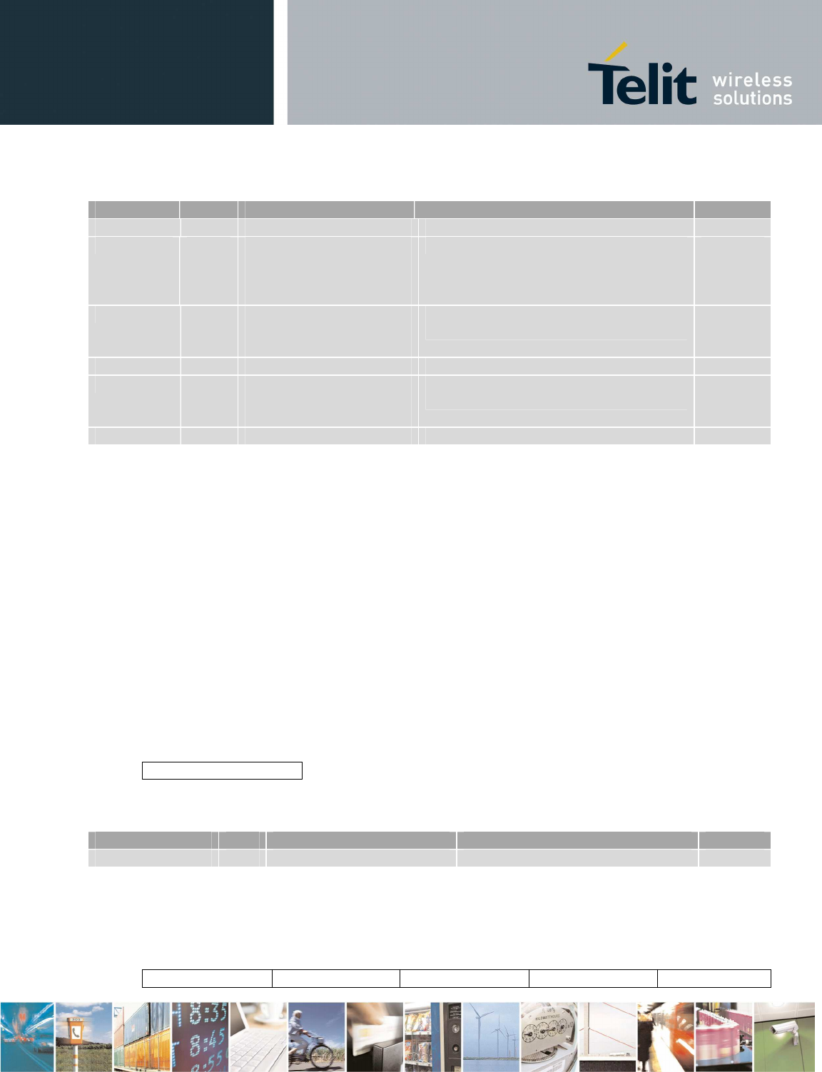
Reproduction forbidden without Telit Communications S.p.A. written authorization - All Rights Reserved page 54 of 73
Field size Valid Range Description Default
Status 2 0x0001-0x0003 Result of the command N/A
DXT list 1 0x00: All the active DXTs
in the network;
0x01: All the active DXTs
from the saved list
Active DXTs or DXT list N/A
bode baro 1 0x00: No data; 0x01:
Last data;0x02: All data;
0x03 Specific data
Get Last Data / All Data / Specific Data
or don’t get data N/A
block baro 2 0-6000 Specific block N/A
mode diver 1 0x00: No data; 0x01:
Last data;0x02: All data;
0x03 Specific data
Get Last Data / All Data / Specific Data
or don’t get data N/A
block diver 2 0-6000 Specific block N/A
4.3.4.31 Get Log File
Get Log application file over serial communication (C1 and C2) or FTP (only C2).
Log application file contains:
•
the last operations done by gateway
o
C1: the operations since boot are always reported
o
C2: if there is an error occurred during previous autonomous mode and this has never
been sent over FTP or serial communication, the operations since this error are
reported, else the operations since boot are reported
•
the actual status of the gateway
•
the DXT list
If control interface is not on serial port, gateway sends log info to RS232 serial port.
OPCODE:0x001F
Where field parameters is:
FTP/serial
FTP/serial parameter is mandatory.
Field
Size
Valid Range
Description
Default
FTP/serial 1 0x00: serial, 0x01: FTP Sending file mode N/A
Get log file response (serial)
If received data length is SIZE, (SIZE/256) packets are received. Every packet is:
Status NumTotPackets Num Len Data bytes
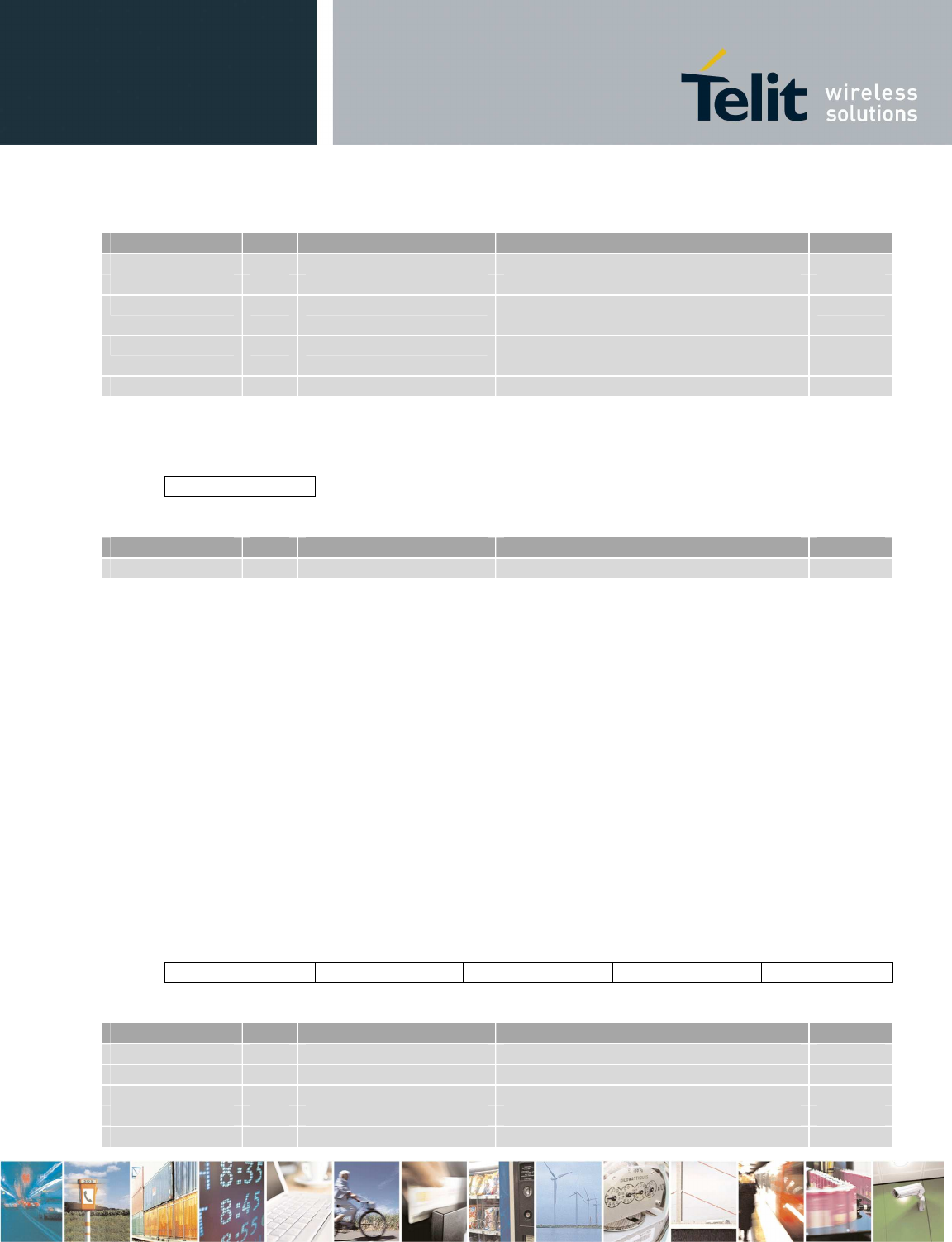
Reproduction forbidden without Telit Communications S.p.A. written authorization - All Rights Reserved page 55 of 73
Field Size Valid Range Description Default
Status 2 0x0001-0x0003 Result of the command N/A
NumTotPacket 2 0-65535 Total number of packets N/A
Num 2 0-65535 Number of the current packet (the first
packet has Num = 0) N/A
Len 1 0-255 Number of bytes to be considered in
the unstuffed Data bytes field – 1 N/A
Data bytes 256 Data Log bytes N/A
Get log file response (FTP) (only for C2)
Status
Field Size Valid Range Description Default
Status 2 0x0001-0x0002 Result of the command N/A
One file is sent to FTP server. Its name has this format:
date_hour.log
4.3.4.32 Get BT parameters
Get BT properties (only for C1)
OPCODE:0x0020
Where field parameters is:
No parameter
Get BT parameter response
Status Local address Local name Host address Host name
Field Size Valid Range Description Default
Status 2 0x0001-0x0003 Result of the command N/A
Local address 6 Address of the local BT device N/A
Local name 30 String Name of the local BT device N/A
Host address 6 Address of the host BT device N/A
Host name 30 String Name of the host BT device N/A
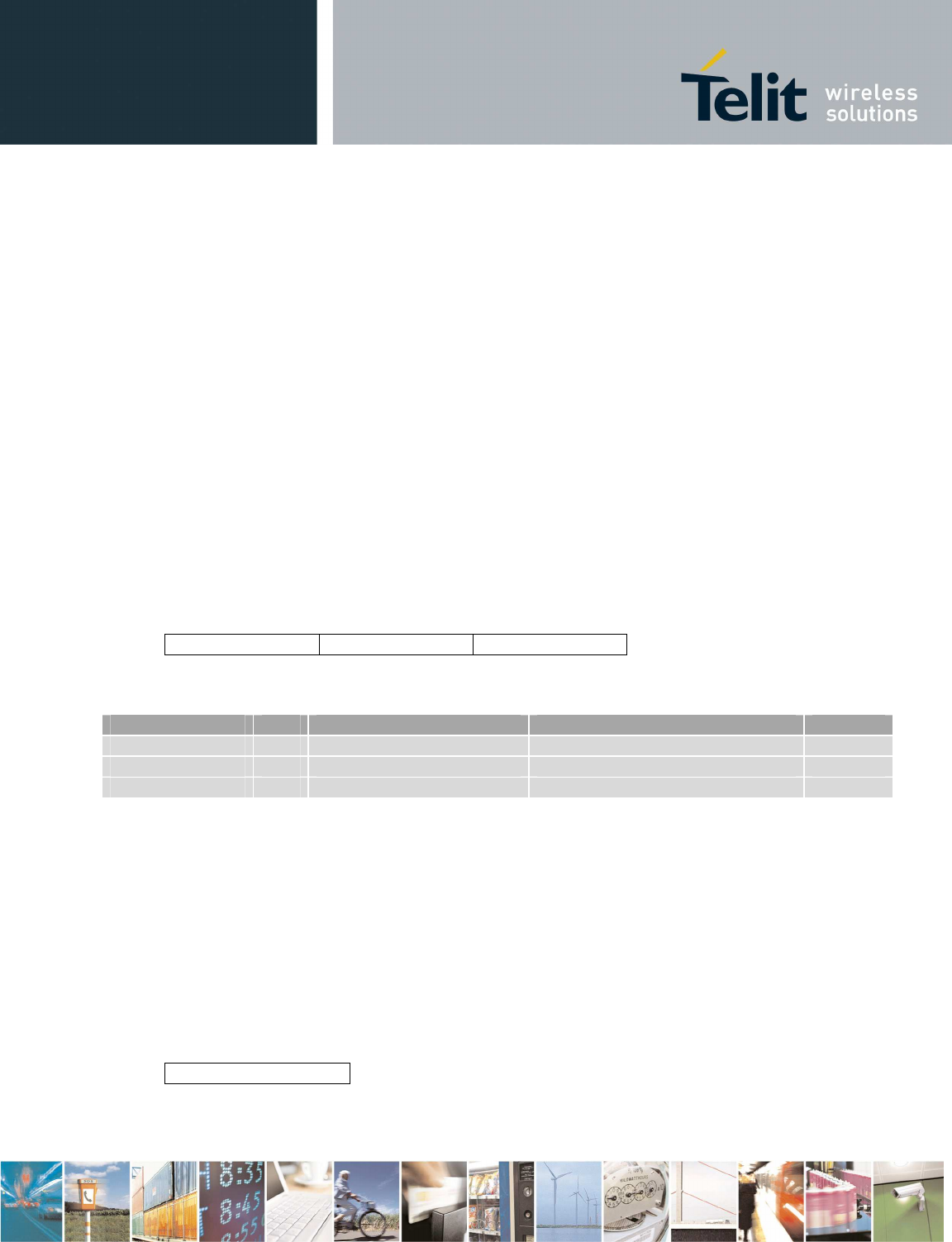
Reproduction forbidden without Telit Communications S.p.A. written authorization - All Rights Reserved page 56 of 73
If no host has been paired, host address is all-zero.
4.3.4.33 Scan for BT devices
Scan for discoverable BT devices. (Only for C1)
Local BT device is not discoverable. This command is not available when BT interface is active.
OPCODE:0x0021
Where field parameters is:
No parameter
Scan For BT response
A
Scan Response,
one for each device, will be received
Parameters field of
Scan Response.
Status Address Name
Next table shows the valid range for the values of the parameters of the
Scan Response
.
Field size Valid Range Description Default
Status 2 0x0001-0x0003 or 0x0008 Result of the command N/A
Address 6 BT address N/A
Name 30 String BT name N/A
When scan is completed, status byte is 0x0008 and the other parameters are meaningless.
4.3.4.34 Add BT host
Put gateway in discoverable state and wait for pairing (only C1). One host can pair with GW. If host
has not a serial profile, it is not paired. When this command is sent, actual BT host is deleted. This
command is not available when BT interface is active.
OPCODE:0x0022
Where field parameters is:
Timeout
Timeout parameter is mandatory.
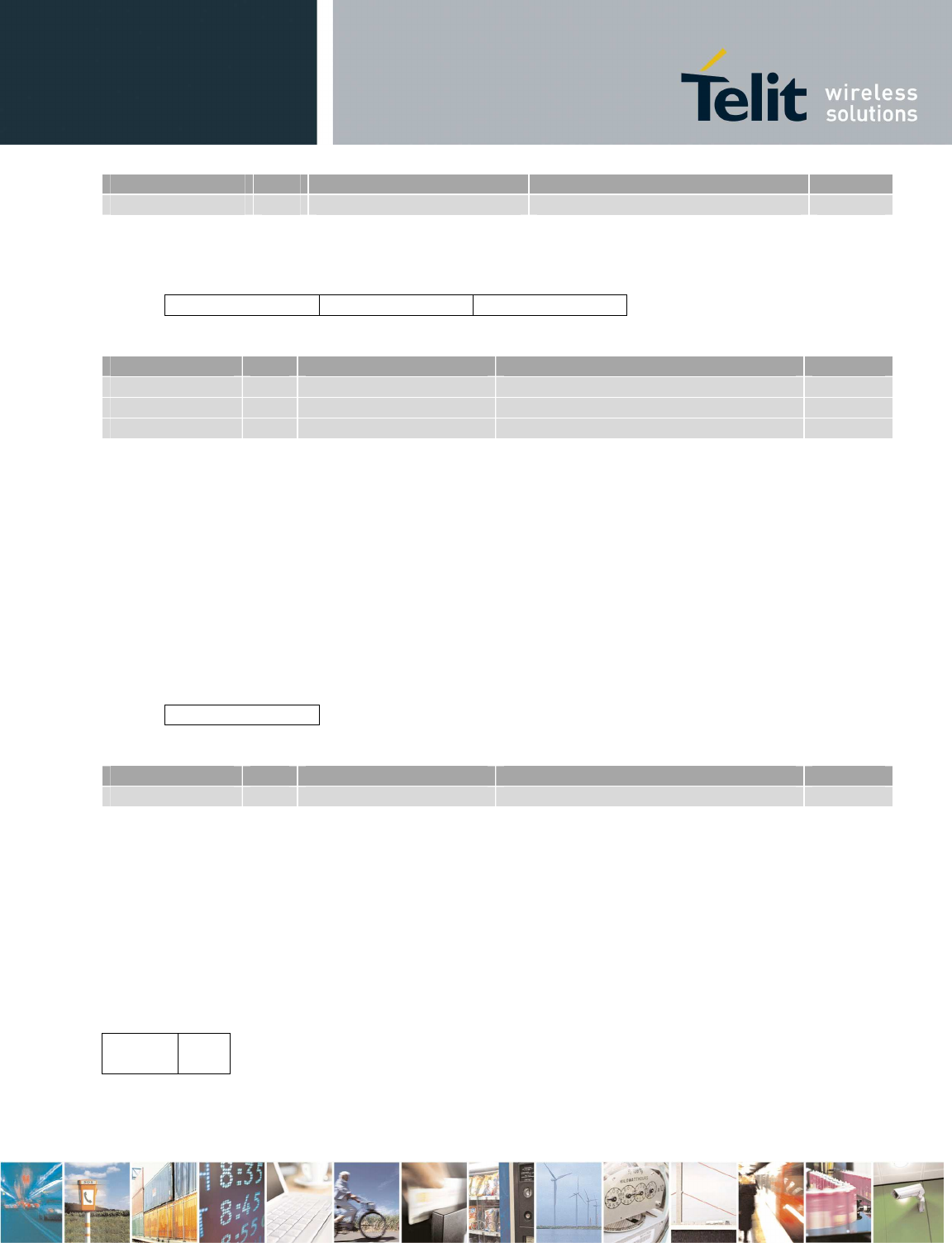
Reproduction forbidden without Telit Communications S.p.A. written authorization - All Rights Reserved page 57 of 73
Field Size Valid Range Description Default
Timeout 1 1-255 GW waits timeout seconds N/A
Add BT host response
Status Address Name
Field Size Valid Range Description Default
Status 2 0x0001-0x0003 Result of the command N/A
Address 6 Host address N/A
Name 30 String Host name N/A
4.3.4.35 Reset BT host
Delete actual BT host (only C1).
OPCODE:0x0023
Where field parameters is:
No parameter
Reset BT host response
Status
Field
Size
Valid Range
Description
Default
Status 2 0x0001-0x0003 Result of the command N/A
4.3.4.36 Set GPRS host parameters
Set parameters for control interface on GPRS (only C2). This command is not available when GPRS
interface is active.
OPCODE: 0x0024
Where field parameters is:
Host
GPRS Host
port
No parameter is mandatory.
Reproduction forbidden without Telit Communications S.p.A. written authorization - All Rights Reserved page 58 of 73
Field size Valid Range Description Default
Host GPRS 30 String Hostname of the machine that
controls GW through GPRS host.name.com
Host port 2 0-65535 TCP/IP port used by GPRS host 6790
Set GPRS host parameters Response
Status
Field size Valid Range Description Default
Status 2 0x0001-0x0003 Result of the command N/A
4.3.4.37 Set FTP parameters
Set parameters for FTP server (only C2).
OPCODE: 0x0025
Where field parameters is:
FTP
server
name
FTP
login
FTP
password
FTP
folder
No parameter is mandatory.
Field size Valid Range Description Default
FTP server name 30 String FTP server hostname ftp.server.com
FTP login 30 String Username for FTP login user
FTP password 30 String Password for FTP login 1234
FTP folder 60 String Folder in the FTP server Temp/telediver
Set FTP parameters Response
Status
Field size Valid Range Description Default
Status 2 0x0001-0x0003 Result of the command N/A
4.3.4.38 Set Wakeup parameters
Set date/hour of the next wakeup (only C2).
OPCODE: 0x0026
Reproduction forbidden without Telit Communications S.p.A. written authorization - All Rights Reserved page 59 of 73
Where field parameters is:
Day Month Year Hour Minutes Polling freq
No parameter is mandatory.
Field size Valid Range Description Default
Day 1 1-31 Day of the month 2
Month 1 1-12 Month of the year 1
Year 1 10-255 Year since 2000 10
Hour 1 0-23 Hour since midnight 0
Minutes 1 0-59 Minutes after the hour 0
Polling freq 2 1-65535 Polling frequency in minutes 1440
Set Wakeup parameters Response
Status
Field size Valid Range Description Default
Status 2 0x0001-0x0003 Result of the command N/A
4.3.4.39 Get GPRS host parameters
Get parameters for control interface on GPRS (only C2).
OPCODE: 0x0027
Where field parameters is:
No parameter
Get GPRS host parameters Response
Status
Host
GPRS
Host
port
Field
size
Valid Range
Description
Default
Status
2
0x0001
-
0x0003
Result of the command
N/A
Host GPRS 30 String Hostname of the machine that
controls GW through GPR
S
N/A
Host port 2 0-65535 TCP/IP port used by GPRS host N/A
Reproduction forbidden without Telit Communications S.p.A. written authorization - All Rights Reserved page 60 of 73
4.3.4.40 Get FTP parameters
Get parameters for FTP server (only C2).
OPCODE: 0x0028
Where field parameters is:
No parameter
Get FTP parameters Response
Status
FTP
server
name
FTP
folder
Field
size
Valid Range
Description
Default
Status 2 0x0001-0x0003 Result of the command N/A
FTP server name 30 String FTP server hostname N/A
FTP folder
60
String
Folder in the FTP server
N/A
4.3.4.41 Get Wakeup parameters
Get date/hour of the next wakeup (only C2).
OPCODE: 0x0029
Where field parameters is:
No parameter
Get Wakeup parameters Response
Status Day Month Year Hour Minutes Polling
freq
Field size Valid Range Description Default
Status 2 0x0001-0x0003 Result of the command N/A
Day 1 1-31 Day of the month N/A
Month 1 1-12 Month of the year N/A
Year 1 10-255 Year since 2000 N/A
Hour 1 0-23 Hour since midnight N/A
Minutes 1 0-59 Minutes after the hour N/A
Polling freq 2 1-65535 Polling frequency in minutes N/A
4.3.4.42 Flash SR
Flash the SR module through the USB virtual serial port. After gateway sends ACK, use ZTC on the
USB virtual serial port. After flashing, in C1 configuration press reset button, in C2 configuration
unplug and plug again the power.
OPCODE: 0x002A
Where field parameters is:
No parameter
Flash SR parameters Response
Only ACK is sent.
4.3.4.43 Get Battery voltage
Get battery voltage and temperature (only for C2). Voltage is read one time during application boot.
Temperature is read one time: in autonomous mode or in GPRS controlled mode during application
boot, in controlled mode when this command is received by gateway.
OPCODE:0x002B
Where field parameters is:
No parameters
Get Battery Voltage response
Field size Valid Range Description Default
Status 2 0x0001-0x0003 Result of the command N/A
Voltage 2 0 – 23000 mV Battery voltage (mV) N/A
sign 1 0x00: positive
0x01: negative Temperature sign N/A
temperature 1 0 - 100 Temperature (°C) (absolute value) N/A
Status voltage sign temperature

Reproduction forbidden without Telit Communications S.p.A. written authorization - All Rights Reserved page 62 of 73
4.4 AT command console (C2)
The “modem” u-boot command performs a pass-through between the modem serial port and the
RS232 port of the gateway.
Command is:
modem uart0 53 18 17
Example on RS232 port (start gateway and enter under u-boot console typing a key before kernel
booting; after “Modem is ready” print, you can send AT commands)
RomBOOT
>
CRC ok loading custom env
U-Boot 1.2.0 (Oct 20 2010 - 15:34:01)- 221 Telit
DRAM: 64 MB
Bank #1
Flash:NAND Numonyx NAND01G-B2C 128MB 1.8V 8-bit
Hardware ECC (ECC data size = 512 bytes)
Nb min erasable unit: 1024
min erasable Size: 131072
Size=134217728 bytes
Logical address: 0x40000000
Block 193 is factory bad (0x41820000)
Block 615 is factory bad (0x44ce0000)
Block 713 is factory bad (0x45920000)
Area 0: 40000000 to 403BFFFF (RO) Primary Bootstrap
Area 1: 403C0000 to 4043FFFF (RO) U-Boot code
Area 2: 40440000 to 404BFFFF (RO) U-Boot Environment
Area 3: 404C0000 to 407BFFFF User Area 1
Area 4: 407C0000 to 47FFFFFF User Area 2
usbser: usb console disabled (usbser_timeout = 0)
In: serial
Out: serial
Err: serial
Hit any key to stop autoboot: 0
U-Boot> modem uart0 53 18 17
Turning on modem
Modem is ready
at
OK
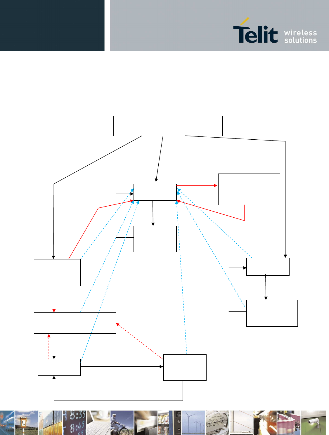
Link with
host device
has been lost
Set Transparent Mode
command
Escape sequence
GW mode is RS232
Escape sequence
Set Transparent Mode
command
GW mode is USB GW mode is BT
No paired device
One paired device
Host device accepts serial
communication
Set Transparent Mode
command
Escape sequence
USB cable is
connected
USB cable is
connected
Link with
host device
has been lost
Command from USB
has been received
Standby command
has been received
5 Appendix: configuration 1 (BT)
Gateway is turned on by user
CI on USB
Transparent
mode on
USB
CI on
RS232
Transparent
mode on
RS232
Has host
device been
paired? (1)
GW in standby mode
waiting for host device (2)
CI on BT Transparent
mode on BT
GW is in standby
mode waiting for
commands from
USB
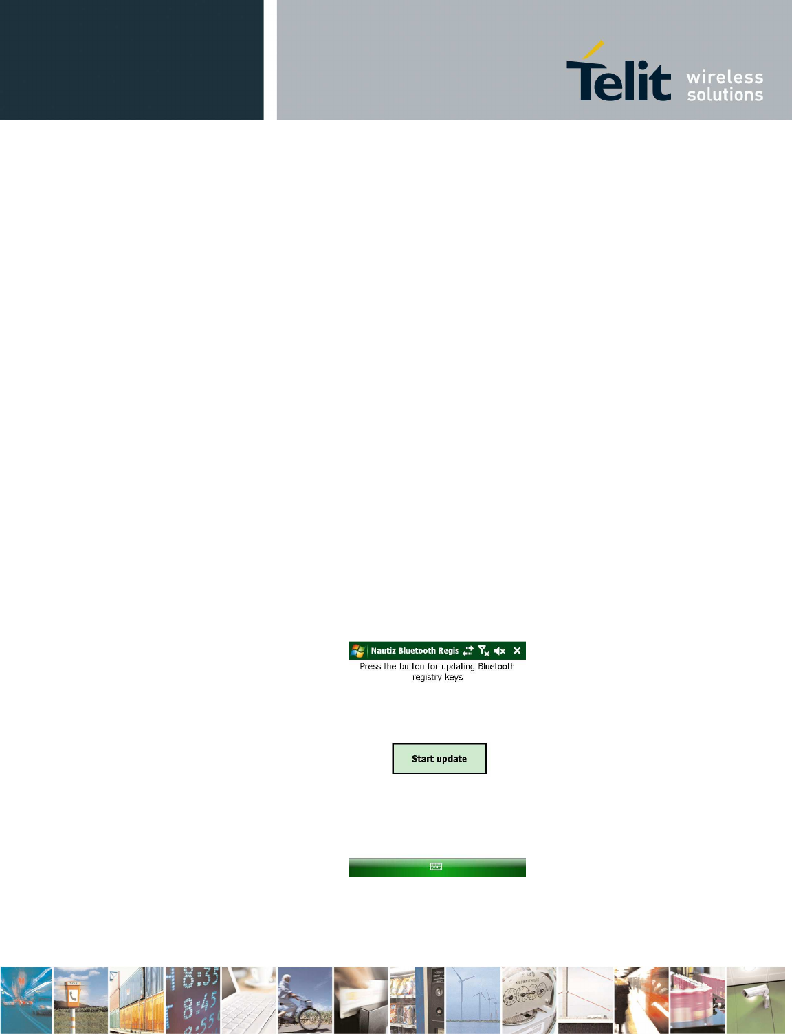
Reproduction forbidden without Telit Communications S.p.A. written authorization - All Rights Reserved page 64 of 73
USB interface is the default mode, so:
•
When gateway is turned at the first time, control interface on USB is started.
•
When USB cable is disconnected and USB interface is active, gateway waits for cable
connecting.
•
If Set Gateway mode command (see 4.3.4.6) is sent during control interface, at the next boot
the new interface will be active.
•
To pass from control interface to transparent mode and vice versa takes at most one second.
•
In order to put gateway in standby mode, use Standby command (see 4.3.4.26). Gateway will
be woken up when a command is received on the active interface.
•
In the state (1), GW checks if there is a registered BT host device. In order to register a BT
host device, use Add BT host command (see 4.3.4.34).
•
When GW is in the state (2), if host device is reachable and accepts serial communication, GW
will be woken up from standby mode and launches CI on BT.
•
In order to turn off gateway, use Turn Off command (see 4.3.4.28). ARM led will turn off and
switch can be moved to “OFF” position after 5 seconds.
•
If battery is too low and power supply from USB is not provided, gateway automatically turns
off.
5.1 BT pairing using Windows Mobile
If a host with Windows Mobile is used, it should be configured in order to export an incoming port on
the BT serial profile.
The following steps configure the PDA (this procedure can be done only one time):
• Modify the Windows registry using NautizRegistry application: click on “start update”
• Under Start/settings/connections/Bluetooth, choose the name associated to the incoming BT serial port
in order to enable it (by default COM0 is show but it is not enabled, it is enabled only choosing it again)
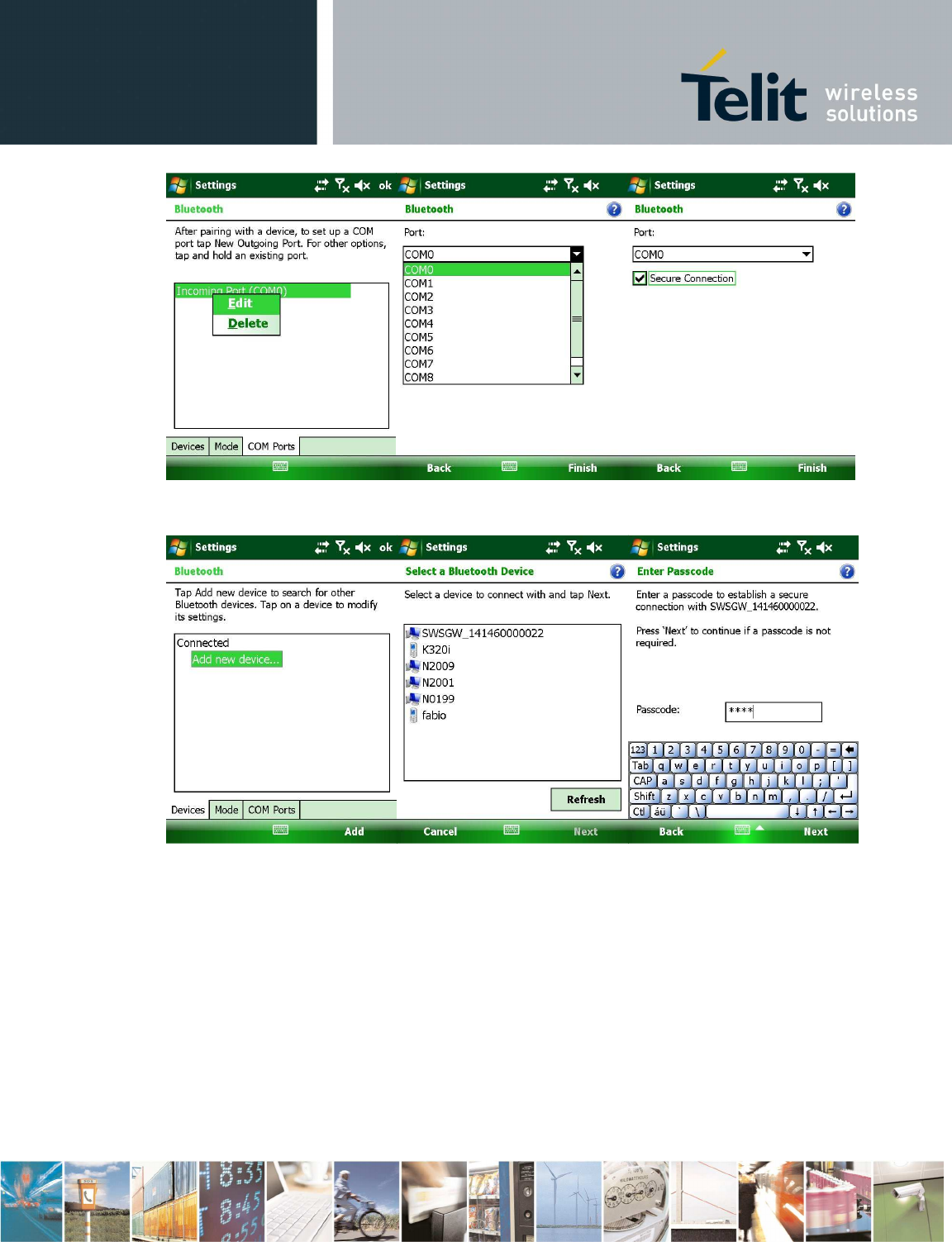
Reproduction forbidden without Telit Communications S.p.A. written authorization - All Rights Reserved page 65 of 73
• Now, SPP is configured. During AddBtHost, host can be registered by gateway:
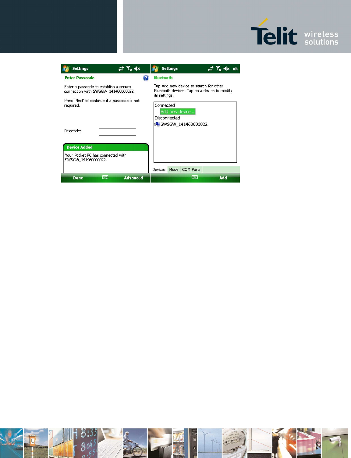
Reproduction forbidden without Telit Communications S.p.A. written authorization - All Rights Reserved page 66 of 73
• In order to enable the control interface on BT, send setGatewayMode and Reboot commands: at the
next reboot, if BT host is visible, gateway will open a serial connection with it (in this example, with the
COM0 serial port).
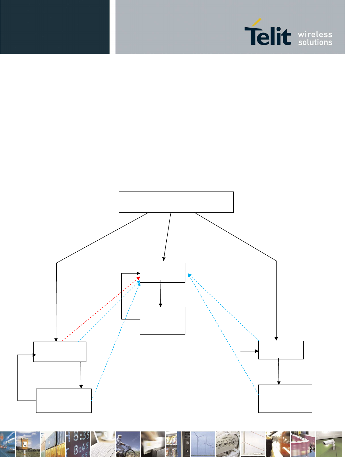
GSM error
USB cable is
connected
Set Transparent Mode
command
GW mode is RS232
Escape sequence
Set Transparent Mode
command
Set Transparent Mode
command
USB cable is
connected
USB cable is
connected
GW mode is USB
GW mode is GPRS
Escape sequence
Escape sequence
6 Appendix: configuration 2 (GSM) -
controlled and autonomous modes
Gateway in configuration2 stays most of the time in deep sleep mode and it can be woken up from
RTC alarm o by wake up button. In the first case autonomous mode is activated while in the latest it
goes directly in controlled mode.
6.1 Controlled mode
Gateway is turned on by user
(wakeup button)
CI on USB
(1)
Transparent
mode on
USB
CI on
RS232
Transparent
mode on
RS232
CI on GPRS
(2)
Transparent
mode on GPRS

Reproduction forbidden without Telit Communications S.p.A. written authorization - All Rights Reserved page 68 of 73
USB interface is the default mode, so:
•
When gateway is turned at the first time, control interface on USB is started.
•
When USB cable is disconnected and USB interface is active, gateway waits for cable
connecting.
•
If Set Gateway mode command (see 4.3.4.6) is sent during control interface, at the next boot
the new interface will be active.
•
At boot time, if USB cable is connected, control interface will be started always on the USB.
•
During functioning, if USB cable is connected, control interface on USB will be started in one
second. Old interface will be again active at the next reboot.
•
To pass from control interface to transparent mode and vice versa takes at most one second.
•
In order to put gateway in deep sleep, use Deep Sleep command (see 4.3.4.27). Gateway can
be woken up by user through wakeup button (controlled mode) or by RTC alarm (autonomous
mode).
•
During autonomous mode, interface on GPRS is enabled: if gateway is turned on in controlled
mode and USB cable is unplugged, control interface is active on GPRS
•
If reset button is pressed while gateway is going to deep sleep, system could reset two times
or go to deep sleep after a reset.
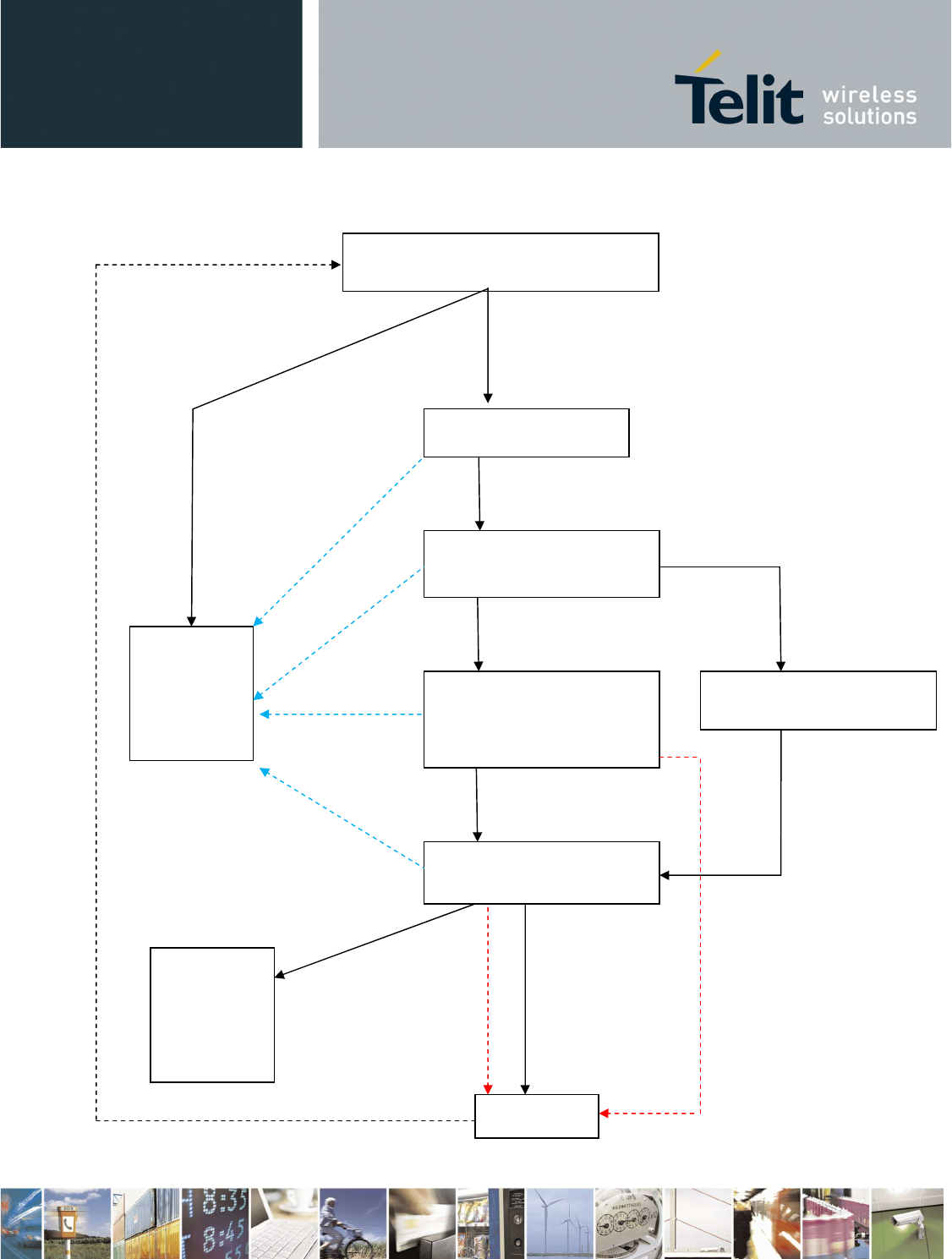
USB cable is
connected
USB is connected
USB cable is
conne
cted
USB cable is
connected
USB cable is
connected
There are active DXTs
There is no active DXT
A command is received before timeout
expires
Timeout has expired
FTP transfer has been
completed
GPRS link is down /
GSM error GPRS link is down /
GSM error
6.2 Autonomous mode
Gateway is turned on by RTC
Turning on SR and
GSM
DXT communication and
GSM registering
Control
interface on
USB: see
(1) in
controlled
mode
SR off, FTP transfer and
starting control interface on
GPRS
Waiting for a command on
GPRS control interface
Control
interface on
GPRS: see
(2) in
controlled
mode
SR off and starting control
interface on GPRS
Deep Sleep

Reproduction forbidden without Telit Communications S.p.A. written authorization - All Rights Reserved page 70 of 73
When it is woken up from RTC:
•
If the USB cable is connected, gateway goes into controlled mode. Otherwise:
•
state “Turning on SR and GSM”:
o
SR and GSM modules are turned on in parallel from ARM9
•
State “DXT communication and GSM registering”:
o
gateway starts one wakeup session and then comm session, while GSM module is
registering to network
o
gateway collects data from DXTs on the basis of Set Auto Dxt Data command (see
4.3.4.15)
o
DXTs to be asked for data: all the active DXTs in the network or all the active DXT
present in the saved list (see 4.3.4.20, 4.3.4.21, 4.3.4.22)
o
each comm slot will be stopped when gateway will receive the
end of data
DXT-frame
from each DXT
•
state “SR off, FTP transfer and starting control interface on GPRS”:
o
DXT communication is finished and SR is turned off
o
FTP transfer: gateway connects to FTP server and sends one file with the format
described in 4.3.4.19. If a previous error has occurred, application log file is
automatically sent (see 4.3.4.31)
o
While data file is sent to FTP server, control interface on GPRS is started (gateway is
the client, host is the server)
o
FTP and GSM parameters are set by Set GSM parameters (see 4.3.4.7)
•
State “Waiting for a command on GPRS control interface:”
o
Once FTP transfer is finished, if a command is received within 45 seconds or had been
received during FTP transferring, gateway goes to controlled mode, otherwise it goes
back to deep sleep (next wake up time is automatically calculated on the basis of Set
GSM parameters - 4.3.4.7)

Reproduction forbidden without Telit Communications S.p.A. written authorization - All Rights Reserved page 71 of 73
7 Conformity Assessment Issues
Configuration 1(BG864-2.4)
The SWS-GW conforms to the following European Union Directives:
•
R&TTE Directive 1999/EC (Radio Equipment & Telecommunications Terminal
Equipments)
•
Low Voltage Directive 73/23/EEC and product safety
•
Directive 89/336/EEC for conformity for EMC
In order to satisfy the essential requisite of the R&TTE 99/5/EC directive, the SWS-GW is
compliant with the following standards:
•
Radio Spectrum. Standards: EN 300 328
•
EMC (Electromagnetic Compatibility). Standards: EN 301 489-1
and EN 301 489-7
•
LVD (Low Voltage Directive) Standards: EN 60 950
NOTE: the device can be used in all EU and in other countries on 2.4 GHz ISM band. When
used in EU countries,
When operating outdoor in France, the emission shall be limited to 10mW in the 2454-
2483.5MHz range.
The power output of the BG864-2.4 has been limited to fulfill the R&TTE recommendation 300
328 in respect of Power Spectral Density (10mW/MHz).
Customers willing to operate the unit within the EU have to order the European version of the
product
For more information please contact Telit Customer Support TS-EMEA@telit.com
Configuration 2 (GG864-2.4)
The SWS-GW conforms to the following European Union Directives:
•
R&TTE Directive 1999/EC (Radio Equipment & Telecommunications Terminal
Equipments)
•
Low Voltage Directive 73/23/EEC and product safety
•
Directive 89/336/EEC for conformity for EMC
In order to satisfy the essential requisite of the R&TTE 99/5/EC directive, the SWS-GW is
compliant with the following standards:
•
GSM (Radio Spectrum). Standards: EN 301 511 and 3GPP 51.010-1
•
EMC (Electromagnetic Compatibility). Standards: EN 301 489-1 and
EN 301 489-7
•
LVD (Low Voltage Directive) Standards: EN 60 950

Reproduction forbidden without Telit Communications S.p.A. written authorization - All Rights Reserved page 72 of 73
NOTE: the device can be used in all EU and in other countries on 2.4 GHz ISM band. When
operating outdoor in France, the emission shall be limited to 10mW in the 2454-2483.5MHz
range.
The power output of the BG864-2.4 has been limited to fulfill the R&TTE recommendation 300
328 in respect of Power Spectral Density (10mW/MHz).
Customers willing to operate the unit within the EU have to order the European version of the
product
For more information please contact Telit Customer Support TS-EMEA@telit.com
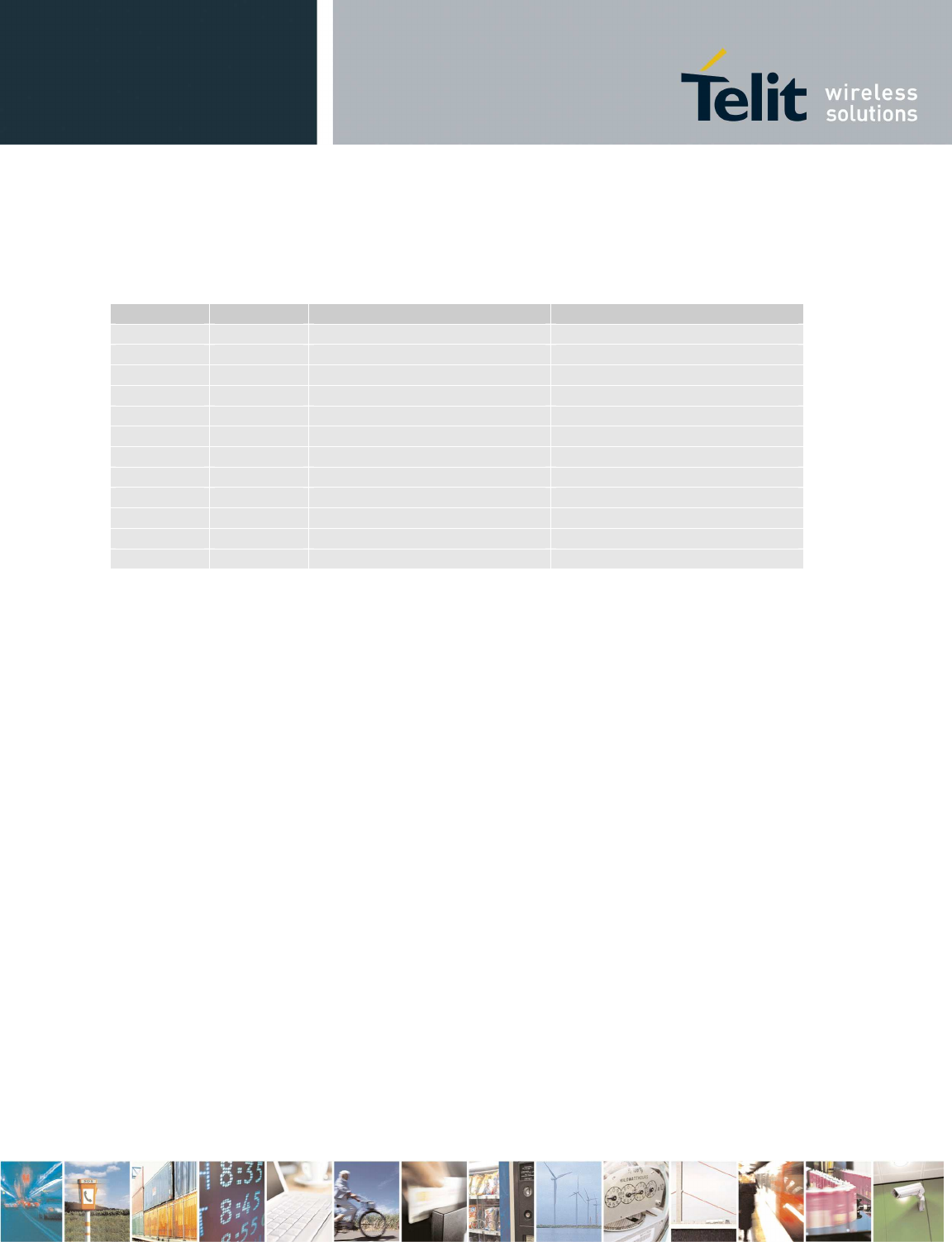
Reproduction forbidden without Telit Communications S.p.A. written authorization - All Rights Reserved page 73 of 73
8 Document Change Log
Revision Date Changes Author
Rev 0 20/02/2011
First issue