Terraboost Media LCDFSAMC04-WF LED Hand Sanitizing Billboard User Manual Advertising Play
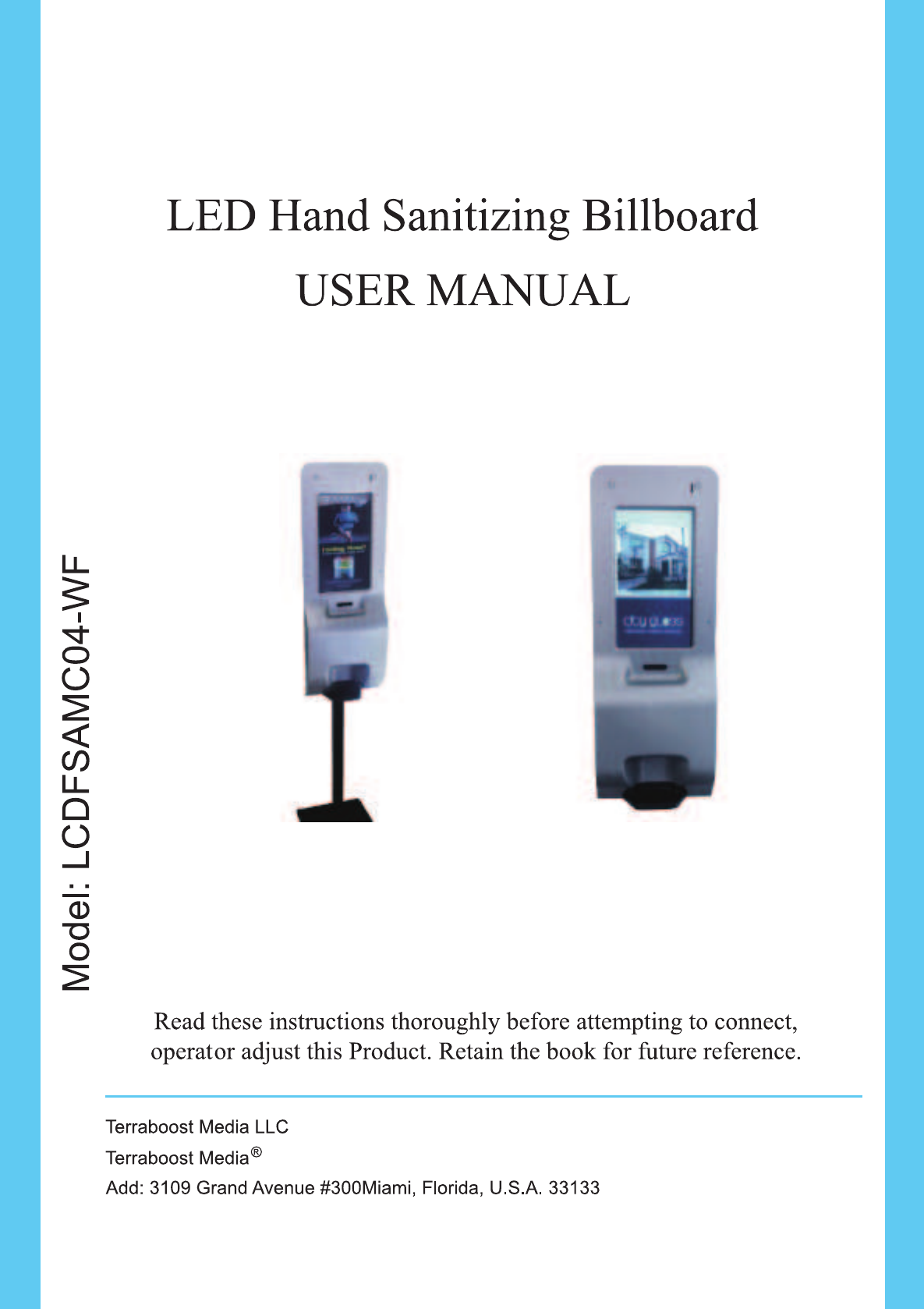
Terraboost Media LLC LED Hand Sanitizing Billboard Advertising Play
Manual
Contents
18.5 AdverƟsing Player User Manual ______________________________________________ 1
Safety InformaƟon__________________________________________________________________1
Before Start _______________________________________________________________________2
Start with SD Card __________________________________________________________________2
Remote Control ____________________________________________________________________3
Install DMB and start Server __________________________________________________________3
Install DMB _______________________________________________________________________________ 3
Start Server _______________________________________________________________________________ 3
Add a Terminal ____________________________________________________________________________ 4
Connect to Server __________________________________________________________________5
Play pictures and videos _____________________________________________________________6
Log in the system __________________________________________________________________________ 6
Upload pictures and videos to server __________________________________________________________ 6
Task Programming _________________________________________________________________________ 7
Other FuncƟons ____________________________________________________________________8
Firmware update __________________________________________________________________________ 8
Language Seƫng __________________________________________________________________________ 8
Terminal Brightness ________________________________________________________________________ 9
Trouble List________________________________________________________________________9
LCD does not show online while checking from Browser? __________________________________________ 9
No display or dark screen____________________________________________________________________ 9
No sound_________________________________________________________________________________ 9
LCD does not download Įles from the server while the status is online _______________________________ 9
InstallaƟon Guide _________________________________________________________________10
1
18.5 Advertising Player User Manual
Safety Information
1. The maximum ambient temperature should not exceed 40ഒ.
2. The LED Hand Sanitizing Billboard shall only used for I.T. Equipment.
3. The main plug is used as disconnect device, the socket-outlet shall be installed near the equipment and shall
be easily accessible.
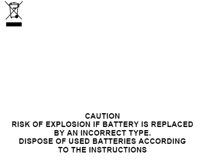
4. Correct Disposal of this product. This marking indicates that this product should not be disposed
with other household wastes throughout the EU. To prevent possible harm to the environment or human health
from uncontrolled waste disposal, recycle it responsibly to promote the sustainable reuse of material resources.
To return your used device, please use the return and collection systems or contact the retailer where the
product was purchased. They can take this product for environmental safe recycling.
5. This product must not be disposed together with the domestic waste. This product has to be disposed at an
authorized place for recycling of electrical and electronic appliances.
6.
Warning: Changes or modifications to this unit not expressly approved by the party responsible for compliance
could void the user’s authority to operate the equipment.
NOTE: This equipment has been tested and found to comply with the limits for a Class B digital device, pursuant
to Part 15 of the FCC Rules. These limits are designed to provide reasonable protection against harmful
interference in a residential installation. This equipment generates, uses and can radiate radio frequency energy
and, if not installed and used in accordance with the instructions, may cause harmful interference to radio
communications.
2
However, there is no guarantee that interference will not occur in a particular installation. If this equipment does
cause harmful interference to radio or television reception, which can be determined by turning the equipment off
and on, the user is encouraged to try to correct the interference by one or more of the following measures:
Reorient or relocate the receiving antenna.
Increase the separation between the equipment and receiver.
Connect the equipment into an outlet on a circuit different from that to which the receiver is
connected.
Consult the dealer or an experienced radio/TV technician for help.
Shielded cables must be used with this unit to ensure compliance with the Class B FCC limits.
Before Start
Before using, make sure that the components are enough (Player, SD Card ,Adapter , Remote Control ).
Note : SD Card has installed the player running programs, please do not format it ,do not do anything to SD
Card .
Start with SD Card
Start to run the play from SD card ,we need following steps :
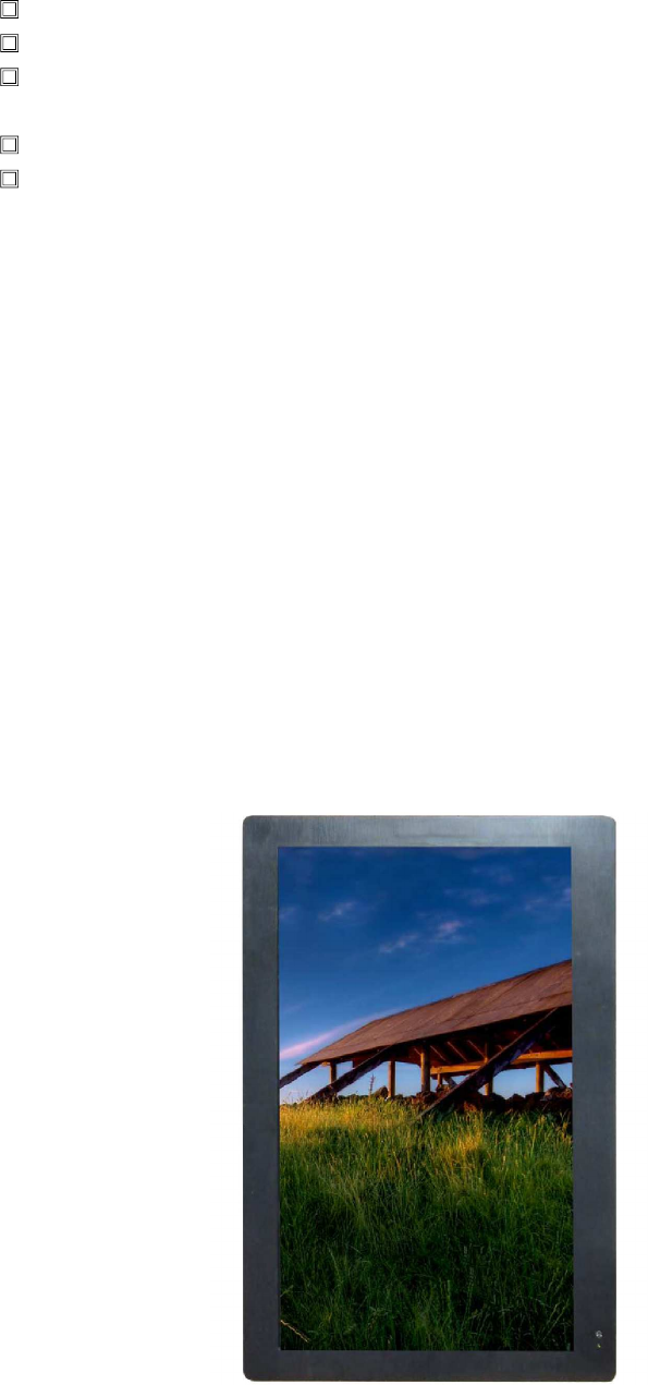
Insert SD card into the SD Card slot , then power on , waiting about 1 minute ,you can see the desktop as
below Chart-1:
Chart-1
In order to comply with FCC's RF radiation exposure limits for general population/uncontrolled exposure, the
antenna(s) used for this transmitter must be installed to provide a separation distance of at least 20 cm from all
persons and must not be collocated or operating in conjunction with any other antenna or transmitter.
3
Remote Control
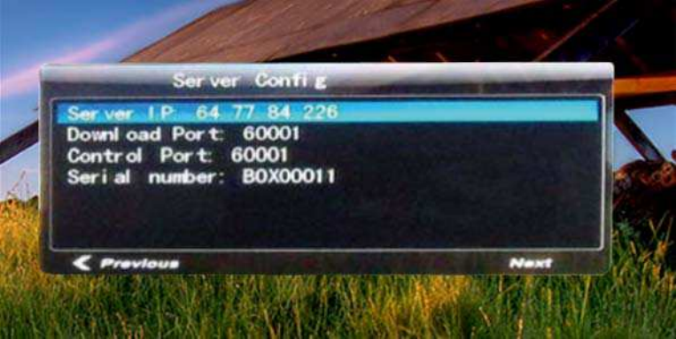
Press *#9879# , and input password 123456 you can enter Terminal Config
Here you need to config the terminal Server , config the terminal Network (including IP, WIFI if necessary).
Terminal Server : input the Server IP number , Download Port 60001, Control Port 60001 , Serial
Number ,see Chart-2:
Chart-2
Note : Download port and control port are all 60001, they can not be changed. Remember the Serial number
Terminal Network
Ethernet Config: set reasonable IP , gateway , Subnet , DNS etc.If you want to use WIFI , see below :
WIFI Config : WIFI is on , Mode is DHCP , ESSID is your Router name , password is your Router access
password , Encro Type is as same as your Router.
When you config all OK , then reboot terminal ..it takes about 1 minute.
Install DMB and start Server
Install DMB
In order to control the terminal , we need to install DMB BS3 Software , the installation details please see
specification.
Start Server
Server Software can install easily and fast , no special setting ,just next.
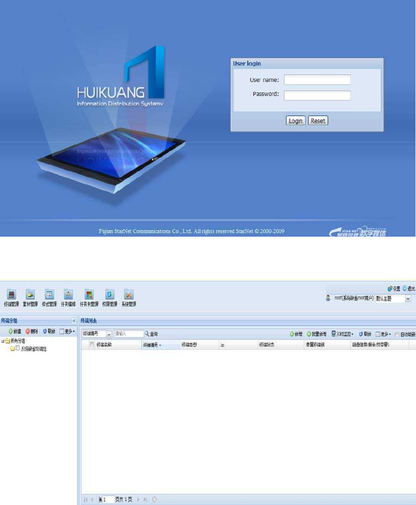
After your installation ,please open IE browse , input http:// Sever IP address˖8080/dmb . the login name and
password are all root. as below: chart-3:
4
Chart-3
First , enter into the Media Box Management :see chart-4:
Chart-4
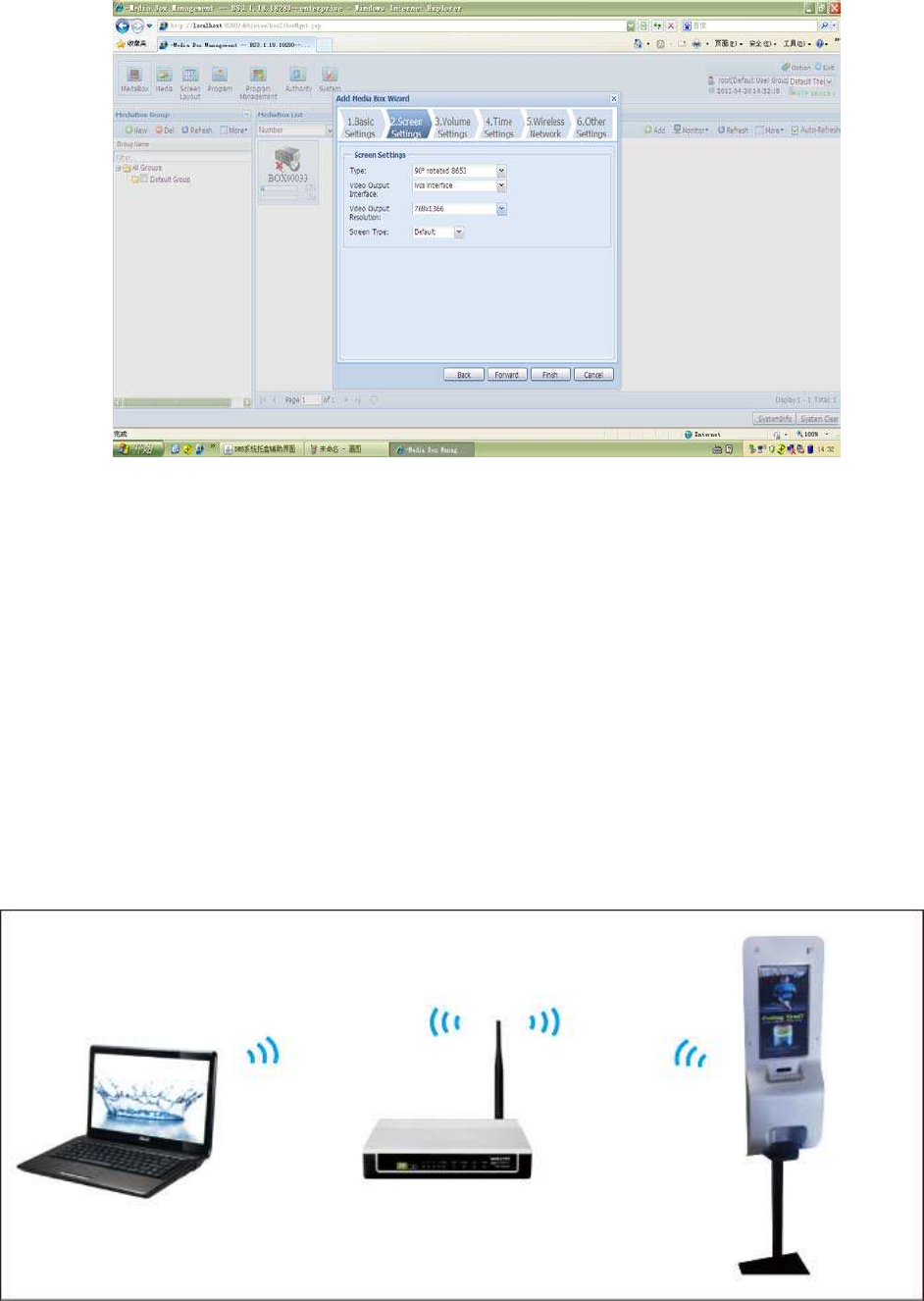
Add a Terminal
Please according to Advertising machine the actual board type and resolution, select the terminal type and
output mode, output mode, the wrong choice may lead to the LCD screen can not display properly or restart . as
chart-5:
5
Chart-5
Connect to Server
Please make sure the configuration you set in Terminal is right.
Build communication between terminal and computer with your wifi network.
We control the Teminal through your Router.
You need to set network between your computer and your Router. See Chart 6:
Chart-6
6
Play pictures and videos
Log in the system
After completing installation of Server, user can open a browser and input
http://<Server IP>:8080/dmb in address bar to open login page as shown in chart-3
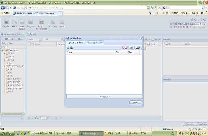
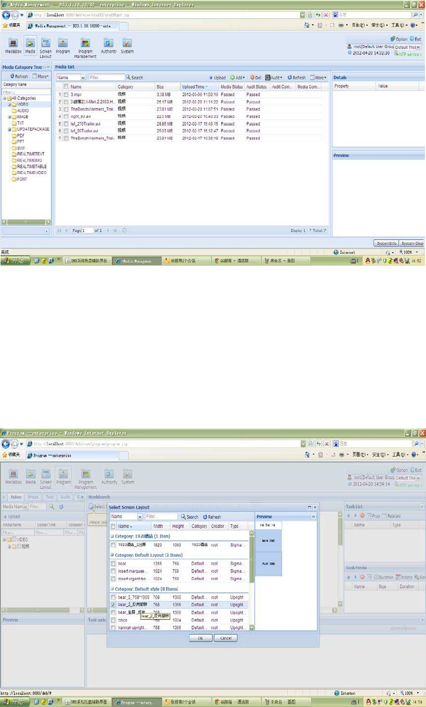
Upload pictures and videos to server
1ǃMedia Management
add media files, upload media files to Server, you can add video, picture, text file , and music etc. Please
choose Media Management , select option the details
Select uploaded videos from local , select group, then “upload”. as below chart-7:
Chart-7
when uploading is finished , pleas wait the Server to convert videos files to the specified content , then click
“approval” . if the files are not audited and passed , the files can not be used. See chart-8:
7
Chart-8
Task Programming
1ǃChoose Style
Click “Task Programming” , then select Styles ( your choose must be right with the terminal you want to add
in) ,then “confirm”. Users can enter the style management page by clicking , No default style is available when
logging the system. Users have to click “import”.
(sigma8653 facilities should have corresponding styles respectively, or troubles will be caused) See chart-9:
Chart-9
8
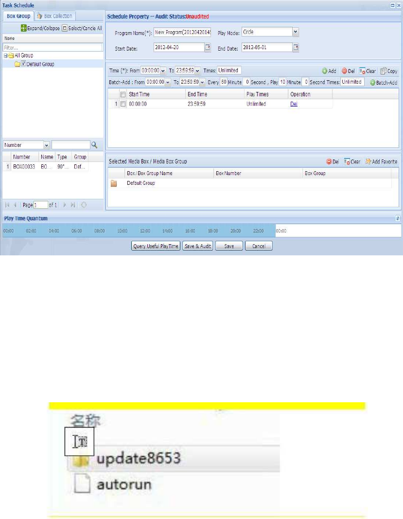
Add Medias
Drag videos from the left media library to the main zone or playing zone , etc. when programming is
finished , save and audit .choose “Save & Audit”. see as below chart-10:
Chart-10
Other Functions
Firmware update
1 Terminal release U disk in the directory Upgrade Kit copied to the root directory of U, such as Chart-11˖
Chart-11
Make sure SD card is format as FAT32 . insert SD card into SD slot . insert U disk.. then turn on power ,wait
about 1 minute and the indicator becomes from red to off . then unplug U disk ,turn off power , and turn on
power again . about 1 minute , it is OK
Language Setting
You can set terminal language : English or Simple Chinese using Remote Control .
9
Also ,you can set DMB Server sofrware language as English or Simple Chinese …
Note : when you change your computer IP , you have to reconfig the DMB and restart Server .
Terminal Brightness
You can set terminal brightness and so on . see details in terminal config .
Trouble List
Please use the following list to do some trouble for the product if necessary.
LCD does not show online while checking from Browser?
Check if LCD connected to the WIFI router by the following steps:
1 login the terminal IP in IE browser
2 select “Network status” and click to see the details . If the WIFI connection is successful , you can see there
an IP address shown there . If not , re-scan the WIFI networking and make sure the password / ESSID/Encro
Type are all right .
3 verify the connection by checking if a computer connected to the same WIFI router can access the internet.
4 Check the Server address setting is correct.
5 Check if there any Firewall in front of Router.
No display or dark screen
1 Check power adaptor if it is working ok
2 Check the connection of power adaptor
No sound
1 Check if the setting is mute or sound level 0
2 Check if the video clip has sound track
LCD does not download files from the server while the status is
online
1 Check if the LCD is assigned to a group and also the group has a valid playlist . if playlist and group setting
are correct ,try to restart the terminal .
2 Check the network status is ok
10
40” 18.5”
© 2012 TERRABOOST MEDIA LLC
digital signage
flex
BY TERRABOOST MEDIA
www.flexsignage.com:8080
©
®
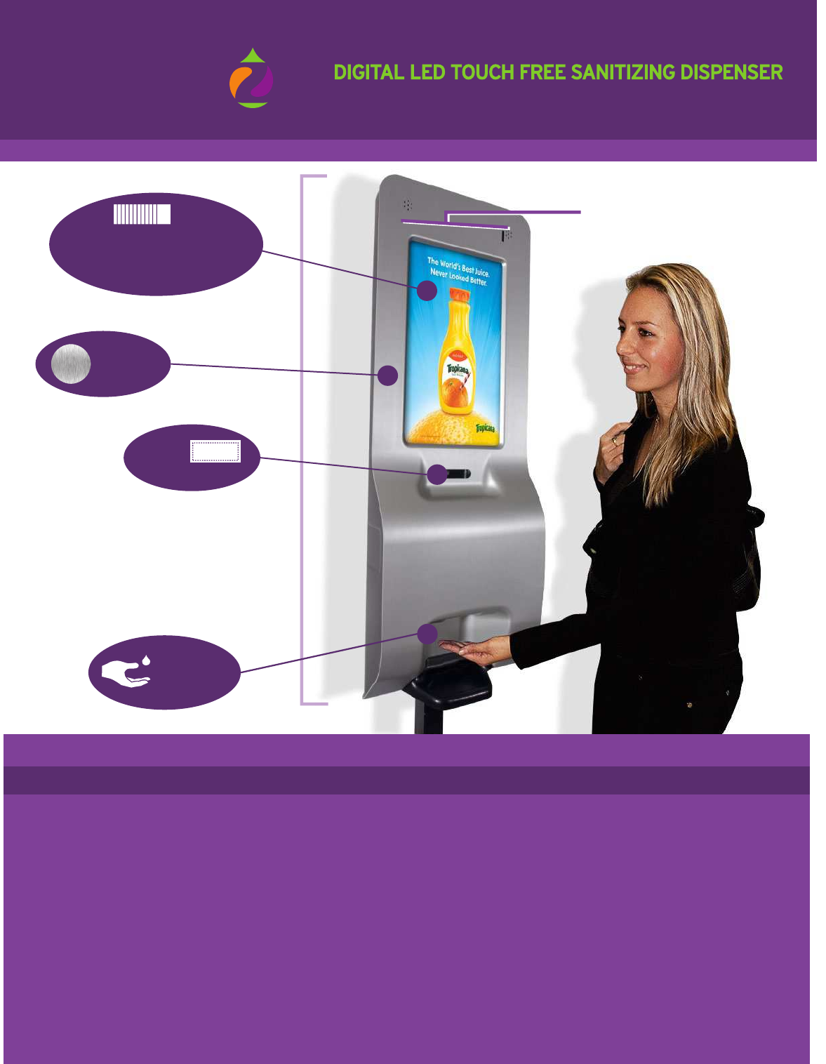
Brushed
Aluminum
Optional
Dispenser
ITEM PARAMETERS SUPPORTED FILE FORMATS
Coupon
12 Ad Slots x 10 Sec. Each.
Screen Capable of Dividing
and Inserting Content
Automatic
Infrared
Dispenser
Supported Video
Supported Photo
Supported Audio
MPEG-1, MPEG-2 MP@HL, MPEG-4.2 ASP@L5, MPEG-4.10 (H.264)
AP@L3, MP@L4.0 and HP@L4.0, WMV9 MP@HL, SMPTE421M (VC-1)
MP@HL and AP@L3
BMP, JPG, JPEG, PNG, GIF
Dolby Digital 5.1, Dolby Digital Plus 7.1, Dolby TrueHD 7.1, DTS 5.1
DTS-HD 7.1, MPEG-1
Layers I, II and III (MP3) 2.0, MPEG-4 AAC-LC 5.1, M E PG-4 HE-AAC 5.1
MPEG-4 BSAC 2.0,
WMA9 2.0, WMA9 Pro 5.1, DVD-Audio with MLP option, Apple iTunes
2.0 (no DRM),
ATRAC3 2.0, 24-bit linear PCM 7.1
LED Screen
Resolution
Brightness
Contrast Ratio
Power Supply
Power Consumption
Memory Card
File System
18.5 inch (diagonal) Digital LED Panel 3:4
1366x768 (RGB)
250nits
1000:1
Adapter, Input: AC100-240V;
Output: 12V/3A 30W (max)
SD card 4G
Embedded Linux OS
2.4L POWER BOOST VERSION (LED DISPLAY) DETAREPO G3 ro IFIW
11
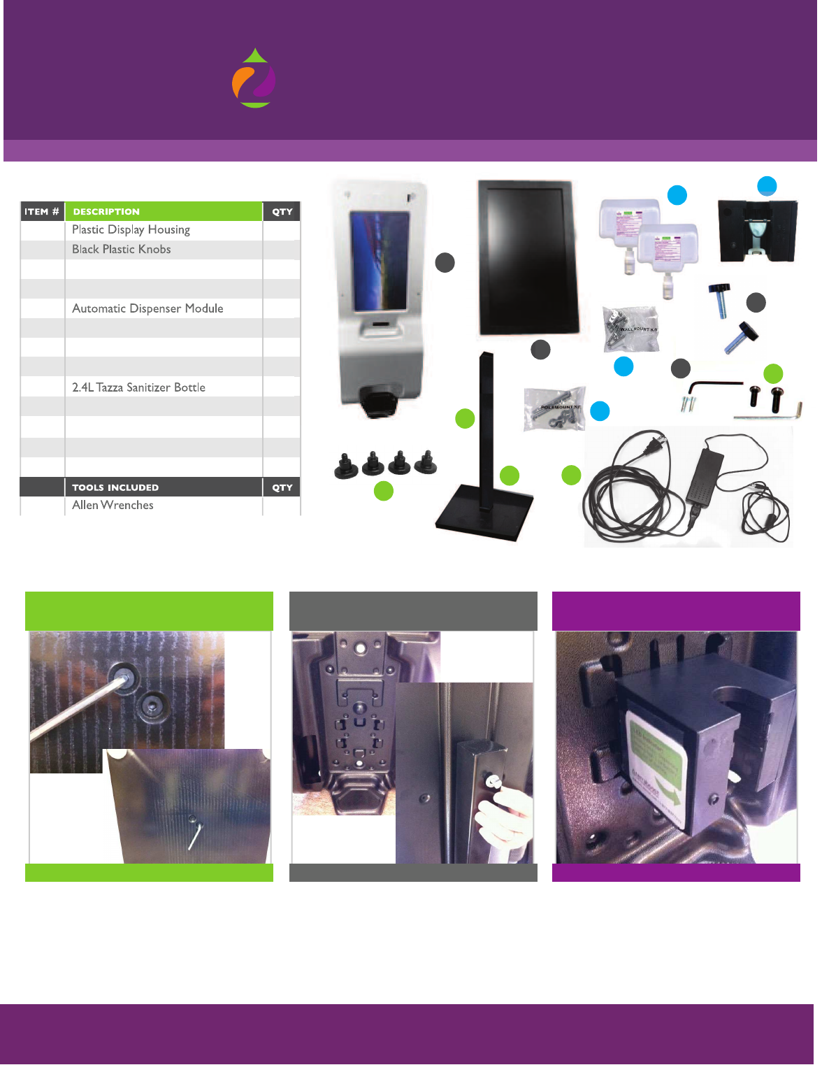
DIGITAL LED DISPENSER ASSEMBLY INSTRUCTIONS
The enclosed pre-numbered list of hardware parts along with
step-by-step directions will enable you to successfully assemble the unit
digital signage
flex
BY TERRABOOST MEDIA
www.flexsignage.com:8080
©
®
FOR MORE INFORMATION, PLEASE CONTACT US AT: advertising@terraboost.com
877-837-7210 | www.terraboost.com
1
2
3
4
5
6
7
8
9
10
11
1
2
1
1
1
2
1
1
1
4
2
2
5
6
9
11
Pole (optional)
Bolts with allen Head for Base
18.5” LED Screen Panel
Small Screw to Lock Dispenser
Base (optional)
Wall Mount Kit
12 4
Head Shoulder Screws for LED
Pole Mount Kit
13 1
AC Adapter
1
7
3
4
Insert the two bolts with the Allen head (item #6) into the
two holes on the bottom of the base (item #4) and screw
into the pole (item #3) with the Allen Wrench provided as
tight as possible.
1
Lift up front cover of the dispenser to match the two holes
in the back of the plastic housing with the two holes in
the pole. Screw either the two black plastic knobs
(Item #2) or the two bolts, washers, and nuts from the
pole mount kit (Item #11) into place to secure the
dispenser housing to the pole. Hand tighten black knobs
or use two 7/16” socket or combination wrenches not
included for bolt/nut method.
2
Locate the battery compartment on the right side of the
module and slide it open to insert the 4 AA Alkaline batteries
in the proper orientation (batteries provided). Click the
“ on/off” switch to “ on” . A red blinking light may be an
indication of an improper installation. Take the module
(as pictured) and press it against the inside of the dispenser
housing and slide down until it clicks into place.
3
BASE & POLE ASSEMBLED
Base & Pole Installation
(Items #3,4,6)
Mounting the Plastic Display
Housing to the Pole & Base
(Item #1)
TIGHTEN KNOBS WITH HANDS OR BOLT/ NUT WITH 2 WRENCHES
Install Batteries & Automatic
Dispenser STEP Module
(Item #5)
MECHANISM IN PLACE
Instructions to Mount LED Screen Power Boost Dispenser to Base & Pole Set
2
© 2012 TERRABOOST MEDIA LLC
2
8
10
13
12
12
DIGITAL LED DISPENSER ASSEMBLY INSTRUCTIONS
The enclosed pre-numbered list of hardware parts along with
step-by-step directions will enable you to successfully assemble the unit
digital signage
flex
BY TERRABOOST MEDIA
www.flexsignage.com:8080
©
®
FOR MORE INFORMATION, PLEASE CONTACT US AT: advertising@terraboost.com
877-837-7210 | www.terraboost.com
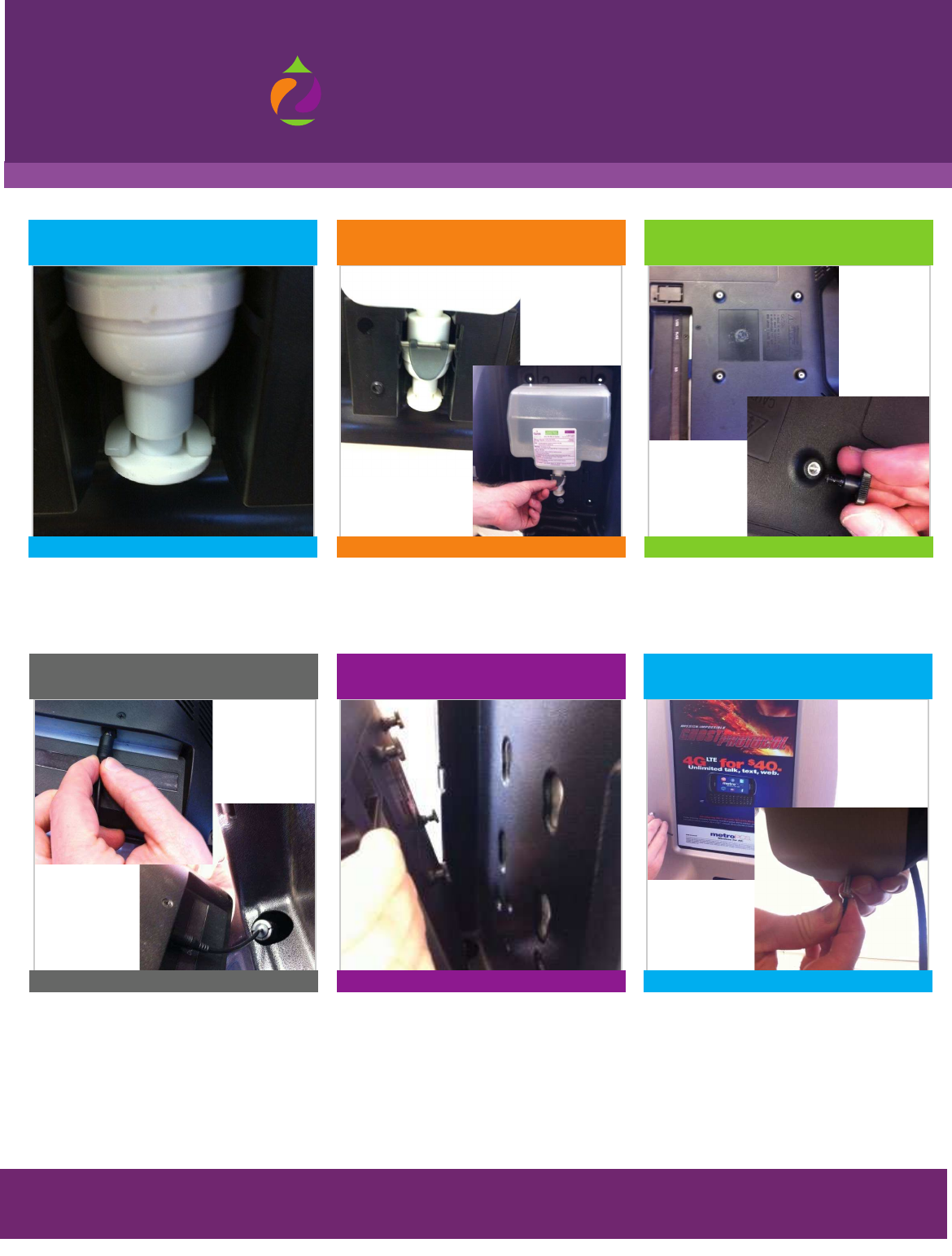
The AC adapter/power cord (item #13) should be
threaded through the unit when you open up the
package. Take the AC adapter and plug one end
into the wall and the other end into the LED
screen (item #7) as pictured above. Please note
AC Adaptor power brick will rest in provided cubby.
7
Plug LED Screen In
Position the four (4) black head shoulder screws
(Item #12) that are now screwed into the back
of the LED screen (item#7) into the grooves on
the back of the display housing (item #1) and slide
into place.
8
Install LED Screen to Dispenser Housing
Take the four (4) small screws to lock the
dispenser (item #8) and place into the four holes
located in the middle and bottom of the display
housing on both the right and left sides (item #1).
Please note to lock dispenser only after initial
LED screen setup including connecting to
WiFi or 3G network.
9
Lock The Display
Take four (4) black head shoulder screws
(Item #12) and hand tighten into the four holes
on the back of the LED screen (Item #7).
6
Prepare LED Screen for Mounting
Remove the pin stopper mechanism from the
dispenser module and insert the bottle with the
nozzle facing downward.
Replace the pin stopper mechanism to secure the
bottle in place as pictured.
4
Install 2.4L Tazza® Sanitizer Bottle
(Item #9)
5
Completed Dispenser &
Bottle Installation
BOTTLE CORRECTLY IN CHAMBER
CORRECT AC ADAPTER INSTALLATION
DISPENSER & BOTTLE CORRECT IN PLACE
SLIDE DOWN TO LOCK INTO PLACE USE ALL FOUR LOCKS
DO NOT OVER TIGHTEN
3
© 2012 TERRABOOST MEDIA LLC
13
DIGITAL LED DISPENSER ASSEMBLY INSTRUCTIONS
The enclosed pre-numbered list of hardware parts along with
step-by-step directions will enable you to successfully assemble the unit
Instructions to Mount LED Screen Power Boost Dispenser to the Wall
digital signage
flex
BY TERRABOOST MEDIA
www.flexsignage.com:8080
©
®
FOR MORE INFORMATION, PLEASE CONTACT US AT: advertising@terraboost.com
877-837-7210 | www.terraboost.com
Locate the battery compartment on the right side of the
module and slide it open to insert the 4 AA Alkaline batteries
in the proper orientation (batteries provided). Click the
“ on/off” switch to “ on” . A red blinking light may be an
indication of an improper installation. Take the module
(as pictured) and press it against the inside of the dispenser
housing and slide down until it clicks into place.
3
Install Batteries & Automatic
Dispenser STEP Module
(Item #5)
MECHANISM IN PLACE
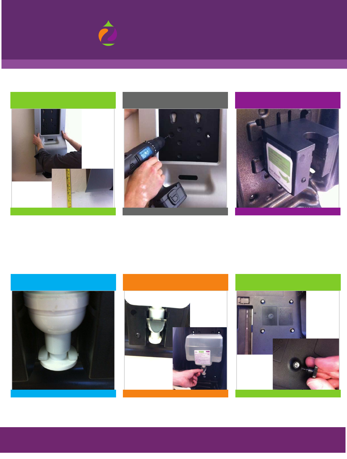
Making sure the display housing is level, drill a 1/4” pilot
hole into the wall in 6 locations through the provided holes
in the plastic display housing (four holes recommended at
the top with two holes in the middle of the bottom section).
Based on the surface you are mounting to, use anchors and
the supplied screws and washers from the wall mount kit to
secure the display housing to the wall (item #10) using a
#2 Philips bit for electrical drill or #2 Philips screwdriver
(not included).
Position the bottom of the display housing (item #1)
approximately 38” from the ground.
12
Mounting the Plastic Display Housing to the WallPosition Dispenser on Wall
PROPER HEIGHT LEVEL ENSURE DISPENSER IS LEVEL
Take four (4) black head shoulder screws (Item #12) and
hand tighten into the four holes on the back of the LED
screen (Item #7).
6
Prepare LED Screen for Mounting
Remove the pin stopper mechanism from the dispenser
module and insert the bottle with the nozzle facing
downward.
Replace the pin stopper mechanism to secure the bottle
in place as pictured.
4
Install 2.4L Tazza® Sanitizer Bottle
(Item #9)
5
Completed Dispenser &
Bottle Installation
BOTTLE CORRECTLY IN CHAMBER DISPENSER & BOTTLE CORRECT IN PLACE DO NOT OVER TIGHTEN
4
© 2012 TERRABOOST MEDIA LLC
DIGITAL LED DISPENSER ASSEMBLY INSTRUCTIONS
The enclosed pre-numbered list of hardware parts along with
step-by-step directions will enable you to successfully assemble the unit
digital signage
flex
BY TERRABOOST MEDIA
www.flexsignage.com:8080
©
®
FOR MORE INFORMATION, PLEASE CONTACT US AT: advertising@terraboost.com
877-837-7210 | www.terraboost.com
The AC adapter/power cord (item #13) should be
threaded through the unit when you open up the
package. Take the AC adapter and plug one end
into the wall and the other end into the LED
screen (item #7) as pictured above. Please note
AC Adaptor power brick will rest in provided cubby.
7
Plug LED Screen In
Position the four (4) black head shoulder screws
(Item #12) that are now screwed into the back
of the LED screen (item#7) into the grooves on
the back of the display housing (item #1) and slide
into place.
8
Install LED Screen to Dispenser Housing
Take the four (4) small screws to lock the
dispenser (item #8) and place into the four holes
located in the middle and bottom of the display
housing on both the right and left sides (item #1).
Please note to lock dispenser only after initial
LED screen setup including connecting to
WiFi or 3G network.
9
Lock The Display
CORRECT AC ADAPTER INSTALLATION SLIDE DOWN TO LOCK INTO PLACE USE ALL FOUR LOCKS
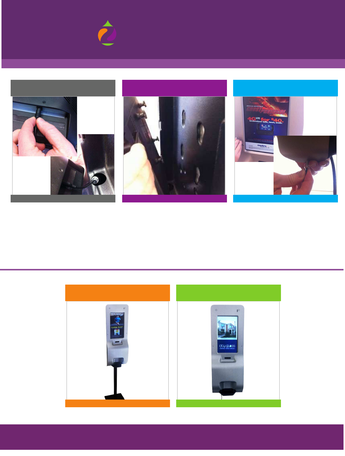
LED Dispenser Properly Mounted on the Wall
LED Dispenser Properly Mounted on the Pole
5
© 2012 TERRABOOST MEDIA LLC
14