The Genie a Division of Overhead Door WKF99 Garrage Door Remote Control Transmitter User Manual page five to eight
The Genie Company a Division of Overhead Door Corporation Garrage Door Remote Control Transmitter page five to eight
Contents
- 1. page five to eight
- 2. inst sheet
page five to eight

SUBMITTAL FOR CERTIFICATION
B8Q WKF99
A GARAGE DOOR TRANSMITTER
FROM
The Genie Company / GMI Holdings Inc.
22790 Lake Park Blvd.
Alliance, Ohio 44601
a wholly owned subsidiary of
Overhead Door Corporation
By
L.Chop Kramer
Sr. Engineering Technician
Phone (216) 821-5360
Date: Sept 15, 1999
Guidelines for this document were derived from the following sections:
2.1033 Application for certification
15.19 Labeling requirements
15.31 Measurement standards
15.33 Frequency range for radiated measurements
15.35 Emission Limits
Subpart C - Intentional Radiators
15.205 Restricted bands of operation
15.209 Radiated emission limits, general requirements
15.231 Periodic operation within the band
40.66 - 40.70 Mhz and above 70 Mhz
I certify:
1) That the enclosed data is an accurate and truthful representation of the product
as tested using ANSI 63.4-1992.
2) That the device meets all the requirements of 15.205, 15.209, and 15.231.
Note: Use View Page Layout and Zoom to view pictures and tables.
2
B8Q WKF99
TABLE OF CONTENTS
TEST EQUIPMENT LIST Page 3
TECHNICAL REPORT Page 4
INSTRUCTION SHEET Page 5
EXPOSITORY STATEMENT Page 9
BLOCK DIAGRAM Page 10
SCHEMATICS Page 11
PHOTOGRAPHS Page 12
LABEL Page 17
REPORT ON MEASUREMENTS Page 18
NOTES ON MEASUREMENTS Page 23

3
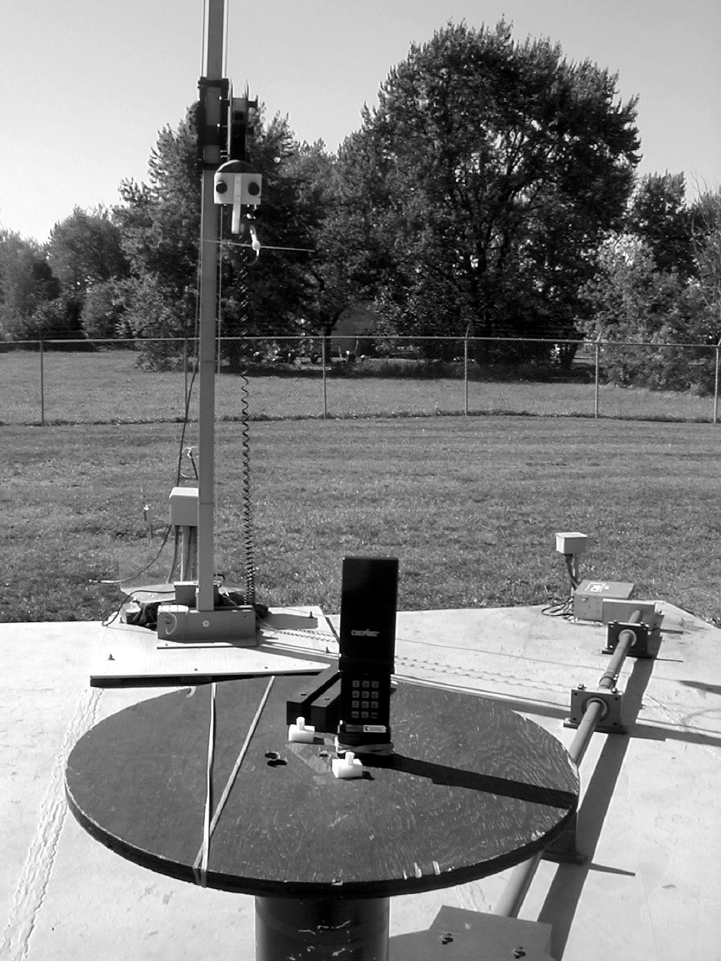
TEST EQUIPMENT LIST
DEVICE MODEL SERIAL
Signal Generator HP 8644A 2933A00424
Spectrum Analyzer HP 8566B 2847A04964
Display 2816A15853
Quasi-Peak Adapter HP 85650A 2524A00802
Amplifier HP 8447D 2443A03986
Dipole Set CD “Robert’s” Set 351
Horn Antenna Emco 3115 2268
Coax (100’) Belden 8214 N/A
Amplifier HP8449B 3008A00576
All above equipment verified to be within manufactures specifications Sept 15,1999.
Site Description
Located at 22790 Lake Park Blvd. Alliance, Ohio. A complete description of the site is on
file with the FCC.
4
B8Q WKF99
TECHNICAL REPORT
MANUFACTURER
The Genie Company / GMI Holdings Inc.
22790 Lake Park Blvd.
Alliance, Ohio 44601
MULTIPLE LISTINGS OF TRANSMITTERS
The Genie Company conducts business under the following trade names:
The Genie Company
The Alliance Manufacturing Company
GMI Professional Access Systems
Overhead Door Corporation
MODEL TRADE NAME
GWKIC-BL GMI Professional Access Systems
GWKIC-12 GMI Professional Access Systems
OWK-CD Overhead Door Corporation
5
6
7
8
9
EXPOSITORY STATEMENT
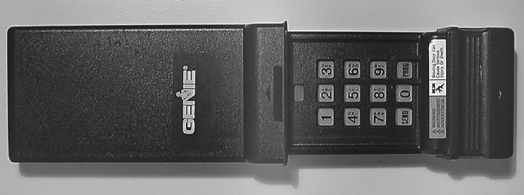
TRANSMITTER DESCRIPTION
The transmitter is a keypad garage door entry system for use with receivers designed by
The Genie Company / GMI Holdings Inc., a wholly owned subsidiary of Overhead Door
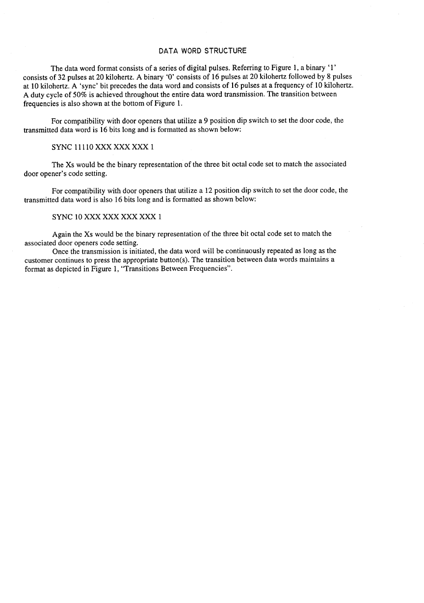
Corporation. The transmitter data transmission is a fixed code 10 and 20 Khz data stream
with a 50% duty cycle that is decoded by the receiver. Tables are included to detail data
structure.
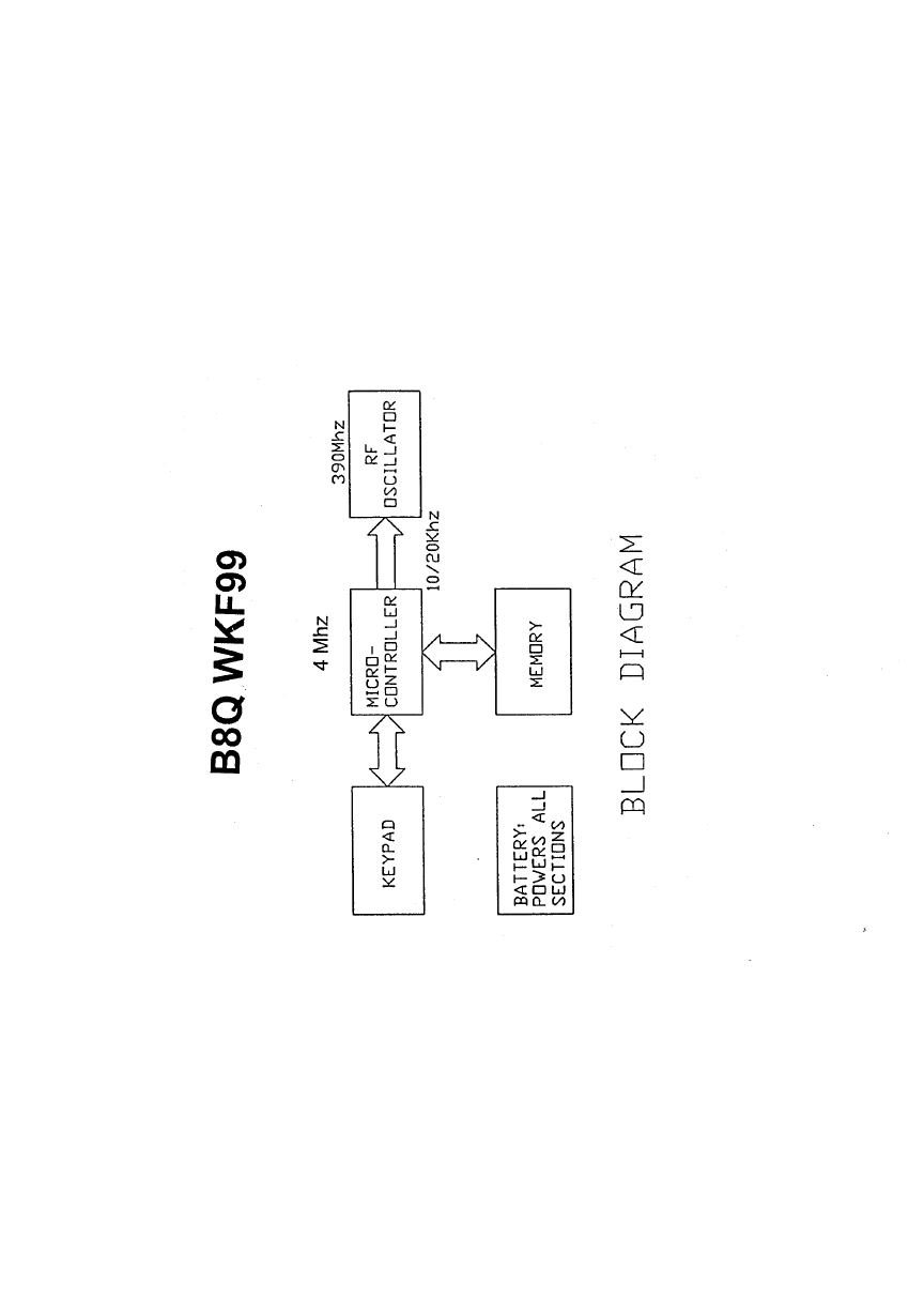
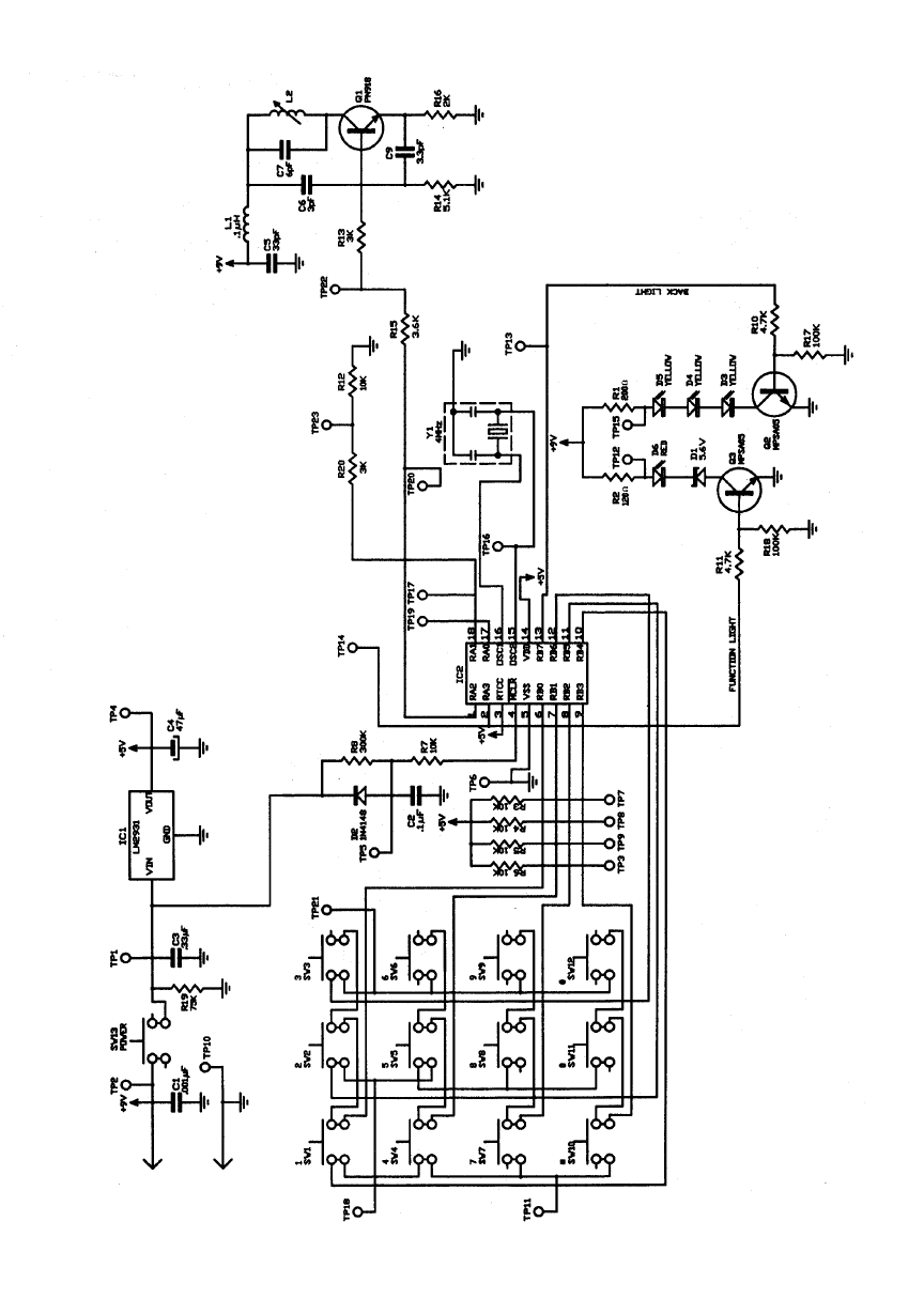
The circuit consists of the following:
• keypad
• micro-controller with resonator controlled oscillator at 4 MHz
• encoder
• RF oscillator (antenna is integral part of the oscillator tank circuit)
• 9 volt battery
When the user enters the proper code sequence, the encoder modulates an RF carrier
which is tuned to a frequency of 390 MHz. See the accompanying schematic and block
diagrams.
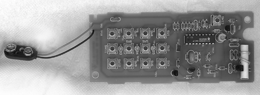
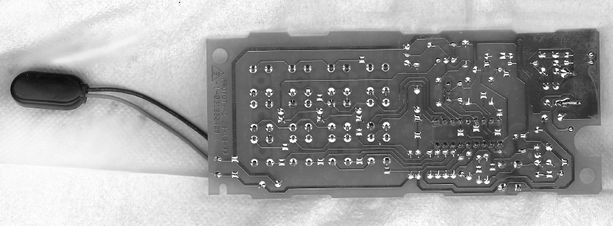
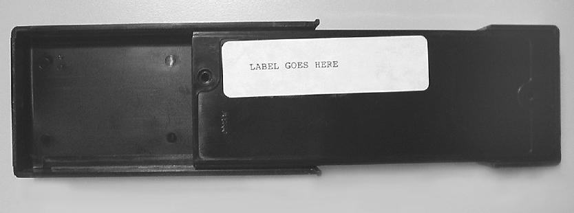
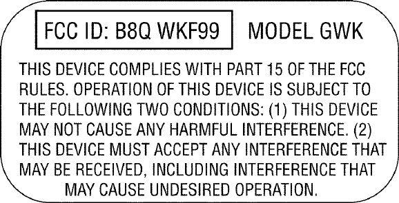
The back of the transmitter has a label with the required FCC text, along with the FCC
identifier, B8Q WKF99, and the model number. An accompanying drawing example
detailing the label is provided. The position of the label is shown in the accompanying
photograph.
10
11
12
13
14
15
16
17
18
REPORT ON
CERTIFICATION MEASUREMENTS
OF
B8Q WKF99 DOOR OPERATOR TRANSMITTER
PREPARED BY:
L.Chop Kramer
Engineering Technician
THE GENIE COMPANY
22790 Lake Park Blvd.
Alliance, Ohio 44601
19
20
21
22
23
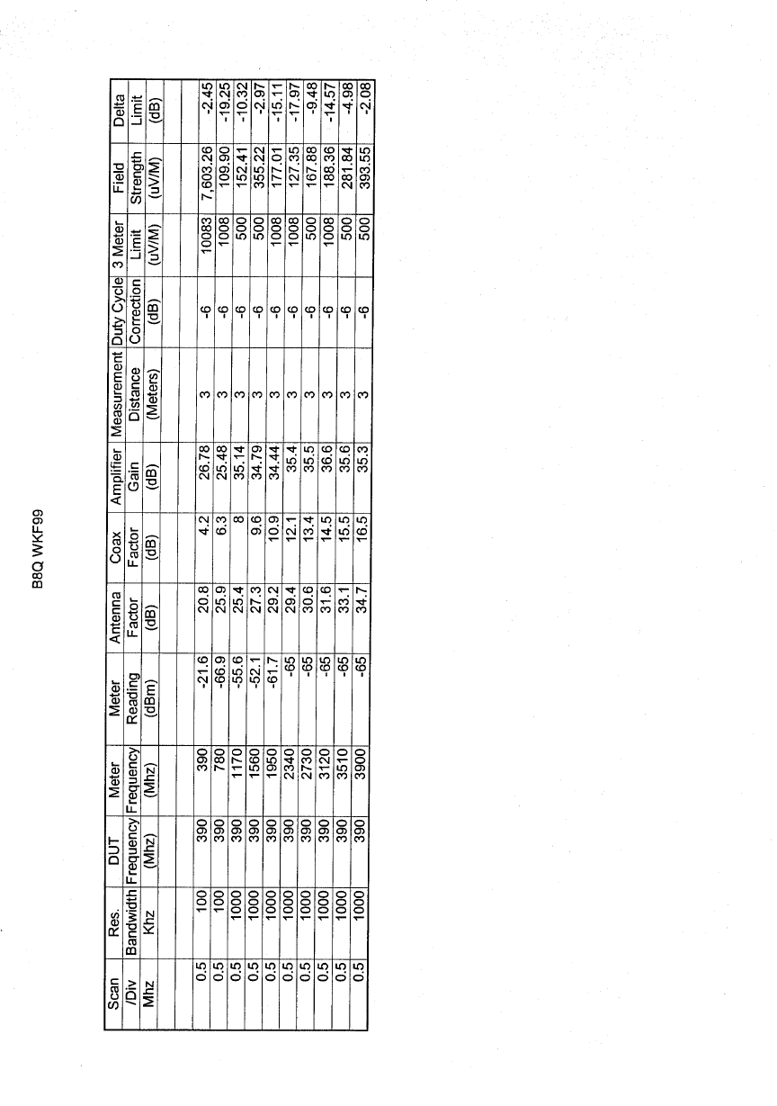
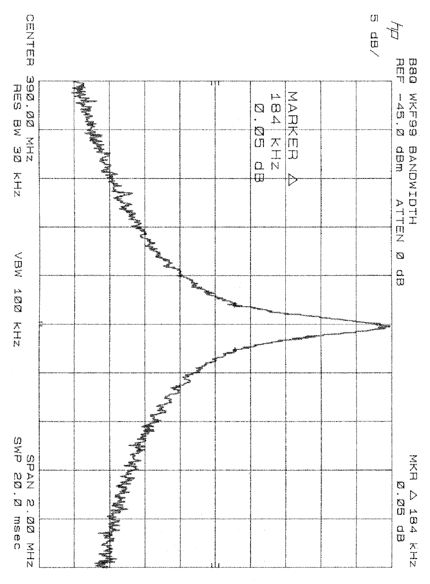
NOTES ON RADIATED EMISSIONS
B8Q WKF99
Sept 15,1999
1) The reported meter readings are the highest levels observed of six positions of the DUT
and the antenna for each frequency.
2) The Measurements up to 1Ghz were taken using the HP8447D amplifier. The
measurements above 1Gnhz were taken using the HP 8449B amplifier.
3) The reading of -65 dBm is the lowest measurement possible with the equipment
available. This level is below the allowed limit in each case.
4) Sample calculation: uV/m = 10 (107 + M + AF + CF - G - DC) / 20
M = -28.0
AF = 2.0 uV/m = 316
CF = 2.0
G = 27.0
DC = 9.0
5) The actual duty cycle is a function of the transmitted code. The transmitted data has a
worst case duty cycle of 50%. This gives the -6dB correction factor in the above equation
and in the Radiated Emissions calculations. Using the data times shown in the expository,
the correction factor calculation is as follows:
correction = 20 * log (25usec/50usec) = -6 dB
6) The transmitters were modified to allow continuous transmission.
7) The transmitter was surveyed for emissions resulting from the local oscillators. No
measurable emissions were present.
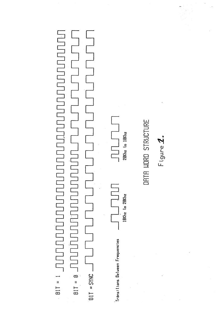
8) A chart of the data word structure is included figure 1.
9) All measurements were made using ANSI 63.4-1992.