TomTom Telematics L0530 Telematic Device User Manual TomTom LINK 530
TomTom Telematics BV Telematic Device TomTom LINK 530
15_L0530 UserMan

TomTom LINK 530
Installation Guide

2
Contents
What’s in the box 4
Read me first 5
Congratulations .................................................................................................................................. 5
What you need for the installation .................................................................................................... 5
Safety first 6
Important safety notices and warnings ............................................................................................. 6
Updating the LINK 530 8
System Requirements ........................................................................................................................ 8
Preparations ........................................................................................................................................ 8
Updating the firmware on your LINK 530 ......................................................................................... 8
Using the XP Compatibility mode ................................................................................................... 11
Activating the LINK 530 12
Connection overview 15
Choosing the correct position 16
Connecting to power 17
Mounting the LINK 530 18
Attaching the holder using the adhesive strips .............................................................................. 18
Attaching the holder using self-tapping screws ............................................................................. 19
Attaching the holder using cable ties .............................................................................................. 19
Testing operation 21
Power or Ignition test ....................................................................................................................... 21
Mobile network reception test ......................................................................................................... 21
Connecting to PRO and WEBFLEET 22
Diagnostics 24
Monitoring operation ....................................................................................................................... 24
Support ............................................................................................................................................. 25

3
Resetting the LINK 530 26
Restarting your LINK ........................................................................................................................ 26
Resetting your LINK to factory settings ........................................................................................... 26
Technical data 27
Appendix: Using external antenna 29
Mounting the external GPS antenna ............................................................................................... 29
Mounting the external mobile network antenna............................................................................. 30
Appendix: Using the IO cable 32
Using the input IN 1 for idle time reporting .................................................................................... 32
Using the input IN 1 for changing the logbook mode .................................................................... 32
Wiring digital inputs ......................................................................................................................... 33
Wiring the digital output .................................................................................................................. 34
Addendum 35
4
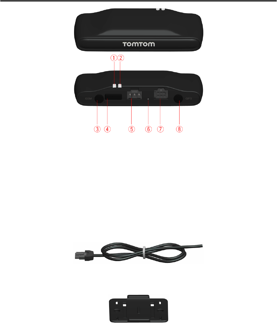
TomTom LINK 530
1. Yellow LED - connection status indicator.
2. Green LED - system status indicator.
3. Connector (SMB) for optional external GSM antenna.
4. Service/Update Mini-USB-cable connector.
5. Power cable connector.
6. Reset button.
7. IO-Cable connector.
8. Connector (SMB) for optional external GPS antenna.
Power cable
Holder
Fixings - 2 adhesive strips and a cleaning tissue
What’s in the box

5
Congratulations
You have chosen the TomTom LINK 530, a core hardware component from WEBFLEET fleet
management solutions. With WEBFLEET from TomTom Telematics you are always connected to
your people out on the road in a smart and easy way.
TomTom LINK 530 is a GPS receiver and mobile network module in one unit, always providing the
vehicle’s current position.
When used with a compatible TomTom navigation device*, you can easily handle orders, as well
as text and status messages. You can receive traffic information, and you are warned when you
are driving or cornering too fast. And you can get information about how much fuel you have
used.
What you need for the installation
Before starting the installation of your TomTom LINK 530, read the safety notices and warnings
carefully and make sure you have the following:
The WEBFLEET Contract Confirmation letter including the Activation Code.
All parts contained in the box.
A connection to the vehicle’s power supply that is fused with max. 10A.
A place with a clear view of the sky where you can move your vehicle to check GPS recep-
tion.
A TomTom navigation device that is compatible with TomTom LINK 530* - optional.
* To check compatibility please visit business.tomtom.com/products
Read me first

6
Important safety notices and warnings
Important: Read the following safety instructions carefully.
TomTom Telematics accept no liability for damage that results from disregarding the safety
instructions.
This document is part of the product. Keep it in a safe place. If you pass the unit on to a new user,
make sure you give them this document as well.
Important - damage caused through improper installation
The installation and initial operation of the unit must be performed by authorised personnel
only for example, a qualified radio dealer or an automotive electronics workshop.
Caution - risk of injury in case of accidents
Do not mount the unit or accessories in the inflation area of airbags or in the impact area for
the head or knees. Choose an installation location that will avoid interference with displays,
safety equipment and controls.
Caution - damage to the chassis
Make sure you do not drill into parts of the chassis that have structural or security-related
functions. This is because you cannot be certain that they will function properly after modifica-
tion.
Caution - risk of fire
Make sure you do not drill into covered wiring harnesses, fuel lines or similar components.
Drilling into these can cause fire.
Caution - use of this product is restricted in some areas
The TomTom LINK 530 contains a mobile network module which can interfere with electrical
devices such as cardiac pacemakers, hearing aids and aviation equipment. Interference with
these devices may endanger the health or life of you or others. If your device includes a mo-
bile network module, do not use it near unprotected electrical units or in areas where the use
of mobile telephones is prohibited, such as hospitals and aircraft.
Caution - danger of explosion
Parts of the TomTom LINK 530 can cause sparks that can lead to explosions. This may en-
danger human health and life. Do not use the unit in areas with high risk of explosion. When
using a TomTom LINK 530 in a vehicle fuelled by liquefied gas, follow the safety regulations of
the country in which the vehicle is operated.
Warning - repair and replacement
Repairs must be carried out by authorised and qualified personnel only. Never replace dam-
aged parts of the unit yourself. Send the defective unit to TomTom Telematics for repair. Only
the qualified staff of TomTom Telematics are authorised to repair or replace parts.
Warning - damage to the device
Safety first
7
Short-circuits inside the unit can be caused by contact with water or other liquids. The unit
may be damaged by contact with water. Use and store the unit in an area protected from wa-
ter.
Caution - risk of accidents
Using a TomTom PRO navigation device while driving is distracting and can cause accidents.
To ensure road safety, only enter information in the navigation device when the vehicle is not
being driven.

8
We recommend updating the firmware on your LINK 530. You can do this by using the Firm-
ware-Update Tool and a Microsoft Windows® computer. A connection to the Internet or
WEBFLEET is not required.
System Requirements
Before you can use the LINK 530 Firmware-Update Tool, you need the following:
The TomTom LINK 530 Service Set.
A Microsoft Windows computer.
The latest LINK 530 Firmware-Update Tool (firmware is embedded).
The USB driver for TomTom LINK 530 devices.
Preparations
1. Install the USB driver.
This is required to establish a connection between your computer and your LINK 530 using the
USB cable.
You can download the USB driver from the Partner Portal. Install the driver on your computer
by double clicking the .exe file and following the instructions.
2. Install the latest Firmware-Update Tool version.
You can download the latest Firmware-Update Tool from the Partner Portal under Software
and Firmware. You must be logged in to the Partner Portal to download the Tool. The down-
loadable ZIP file contains the tool with the firmware update file embedded. Unzip the down-
loaded file to your local hard disk.
Updating the firmware on your LINK 530
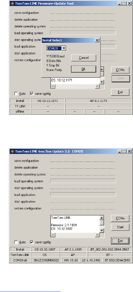
To update the firmware on your LINK 530 using the Firmware Update Tool, do the following:
1. Connect your LINK 530 to a Microsoft Windows® computer using USB.
The first time you connect a LINK 530 to your computer’s USB port, a pop-up window tells you
about the installation of the hardware. Follow the instructions and select automatic installation.
A virtual COM port named TomTom LINK followed by a port number is assigned.
To find out the port number, do the following: Open the Windows Control Panel. Select the
Hardware tab. Select Device Manager. Open the list for Ports (COM & LPT).
2. Start the Firmware-Update Tool by double clicking on the .exe file.
On a computer with Microsoft Windows® Vista or Windows® 7, you must run the tool in
Windows© XP compatibility mode.
Updating the LINK 530
9
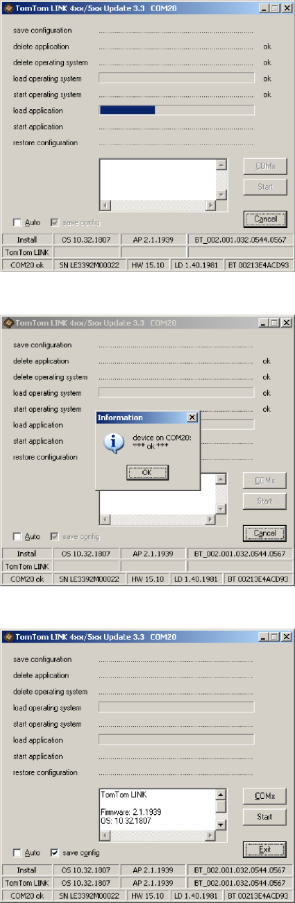
3. Select the COM port that was assigned to your LINK 530 from the list and click OK.
At the bottom of the window you can find information about the operating system installed on
the LINK 530, the serial number of the LINK 530 and which COM Port number was assigned, as
well as the operating system that will be installed with this update.
If the version number of the firmware installed on your LINK 530 is lower than the one includ-
ed in the Firmware-Update Tool, continue with the next ystep. If it is up-to-date, disconnect
your LINK 530 and activate your LINK 530.
4. Select Start to initiate the firmware update installation process.
10
The old firmware is deleted and the new firmware is installed on the device. During the instal-
lation process the upper part of the window displays the installation progress.
5. When the firmware installation is complete, click OK to confirm.
6. To close the Firmware-Update Tool click Exit.
11
Exit closes the application. If you want to install the firmware on multiple devices, disconnect
the USB cable from the updated device and connect it to another LINK 530. The tool automat-
ically recognises the new connection and you can repeat the installation as described above.
Using the XP Compatibility mode
If you want to use the LINK 530 Firmware-Update Tool on a computer with Microsoft Windows
Vista or Windows 7, you must run the tool in Windows XP compatibility mode as it is not compat-
ible with newer versions of Microsoft Windows.
To run the Firmware-Update Tool in XP compatibility mode, do the following:
1. Go to the installation folder of the Firmware-Update Tool on your computer and locate the
.exe file.
2. Right click on the .exe file and select Properties.
3. Select the Compatibility tab.
4. Select the checkbox for Run the program in compatibility mode for:.
5. Select Windows XP from the list and then click OK.
The tool can now be used on a computer with Microsoft Windows Vista or Windows 7.
12
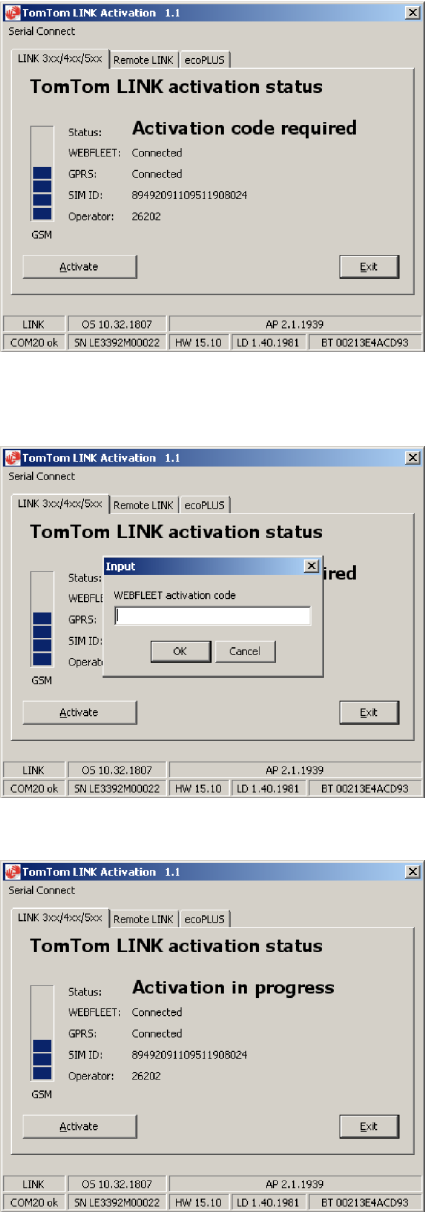
After you have updated your LINK 530 with the latest firmware version you need to activate the
LINK 530 using the TomTom LINK Activation Tool. You can also activate your LINK 530 using a
PRO navigation device.
To activate your LINK 530 using a computer you need to connect it using a USB cable. Download
the USB driver from the Partner Portal and install the driver on your computer by double clicking
the exe file.
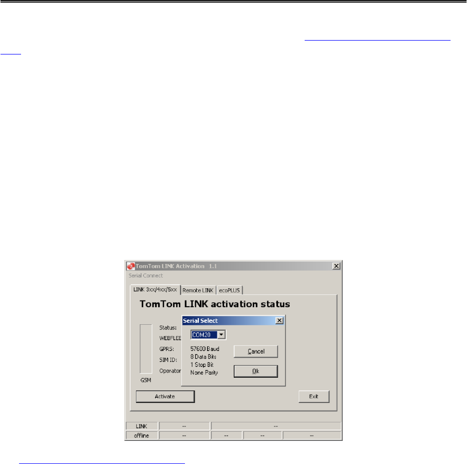
To activate your LINK 530 do the following:
1. Install the latest version of the TomTom LINK Activation Tool.
You can download the Activation Tool from the Partner Portal at
https://business.tomtom.com/10001/areas/reseller/index.xml. Go to Techinical Support and
select Activation and Diagnostics.
2. Connect your LINK 530 to supply voltage.
3. Connect your LINK 530 to your computer using the Mini USB cable.
4. Start the TomTom LINK Activation Tool by double clicking the icon.
5. Click Serial Connect and select the COM port to which you have connected your LINK 530.
6. Monitor the yellow connection LED on your LINK 530 until it indicates that the device has
established a connection to WEBFLEET.
Activating the LINK 530
13
When the connection to WEBFLEET has been established the Activation Tool asks you to enter
your activation code.
7. Click Activate.
8. Enter the Activation Code, which you can find in your WEBFLEET contract confirmation.
9. Click OK.
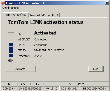
14
The progress of the activation is shown.
You have now successfully activated your TomTom LINK 530.
15
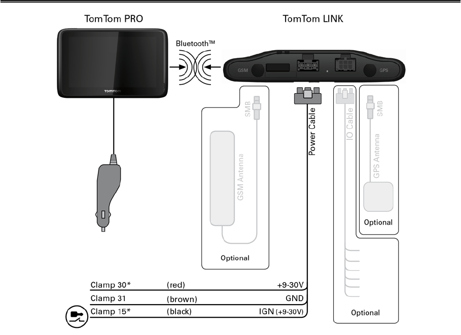
* Make sure this wire is fused with max. 10A.
Connection overview
16
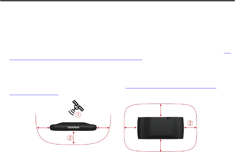
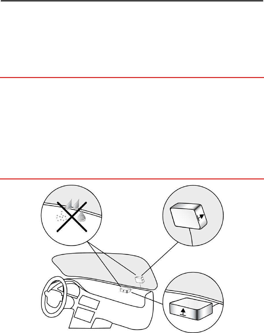
First you need to choose the correct position in which to install your LINK 530.
Take the following into consideration:
Do not expose the LINK 530 to direct sunlight and/or high temperature for long periods to
ensure proper operation.
To ensure GPS reception using the integrated GPS receiver, the top of the device must not be
obstructed by metal items. For more flexibility with regards to installation we recommend us-
ing the external GPS antenna from TomTom Telematics.
To ensure mobile network reception using the integrated mobile network antenna, the device
must not be placed on or surrounded by metal items such as the vehicle’s coachwork closer
than 5 cm (2 inches) and the top side must not be obstructed by metal items. For more flexi-
bility with regards to installation we recommend using the external GSM antenna from
TomTom Telematics.
1. Top side of the device must not be obstructed by metal items.
2. Keep minimum distance of 5 cm (2 inches) to metal items.
Choosing the correct position
17
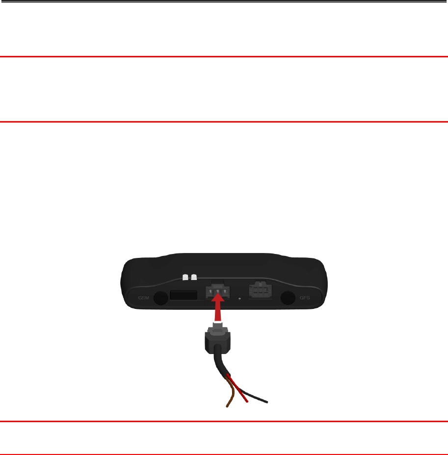
Connect the LINK 530 to the vehicle power supply with the standard vehicle voltage (12 V/24 V).
Do not connect to a voltage converter. The three wires GND, IGN and PWR+ (supply voltage)
must be connected.
Important: Follow the order of connecting the wires as described below. First connect the wires
then insert the plug into the LINK 530.
If you have inserted the plug into the LINK 530 first, you must connect the GND wire before you
connect the PWR+ wire and the IGN wire as described below.
1. Connect the GND wire (brown) to ground (clamp 31).
2. Connect the PWR+ wire (red) to the carry current (clamp 30).
The connection must be fused with max. 10A. If not, fuse the the PWR+ wire with one 2A fast
blow fuse.
3. Connect the IGN wire (black) to ignition (clamp 15).
The connection must be fused with max. 10A. If not, fuse the the IGN wire with one 2A fast
blow fuse.
4. Insert the 3-pin plug into the power cable connector.
If you need to disconnect the wires while the 3-pin plug is plugged in the LINK 530 make sure you
disconnect the GND wire last.
Connecting to power
18
Your LINK 530 comes with an integrated mobile network antenna and an integrated GPS antenna.
Depending on the position you choose for the installation, you can install your LINK 530 without
external antennas.
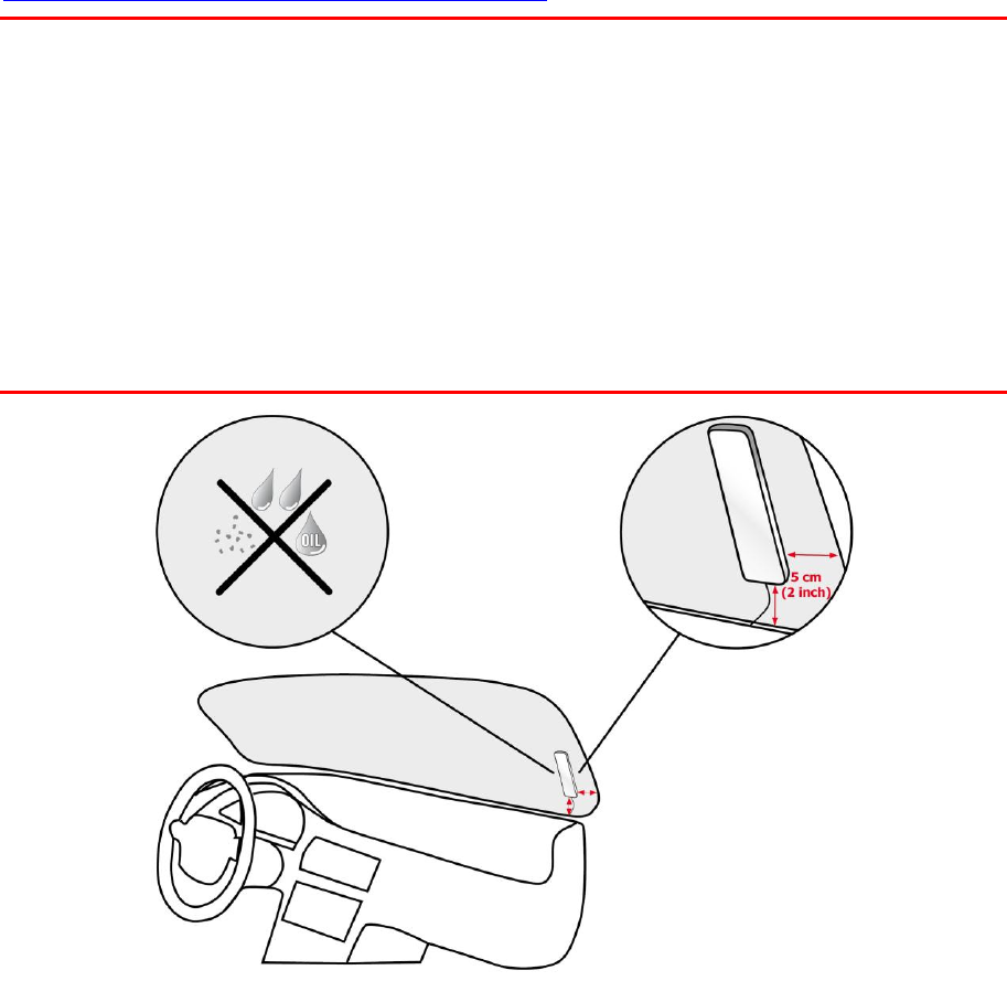
The device must be positioned so that it is unobstructed by metal objects.
The device must not interfere with clear vision for the driver.
Tinted metallised windscreens or those with integrated filament heating may block GPS re-
ception.
Place the unit a minimum of 5 cm (2 inches) distance to the coachwork or other metal items,
so that optimal mobile network transmission and GPS reception is ensured.
The unit must be placed on an oil free, dry and clean surface, when using the adhesive strips.
Extreme temperature changes/differences can affect the adhesive property of the strips.
Before installing the device, please consider the safety instructions and choose the correct
position.
The LINK 530 can be attached with the two adhesive strips, the two tapping screws or the cable
ties.
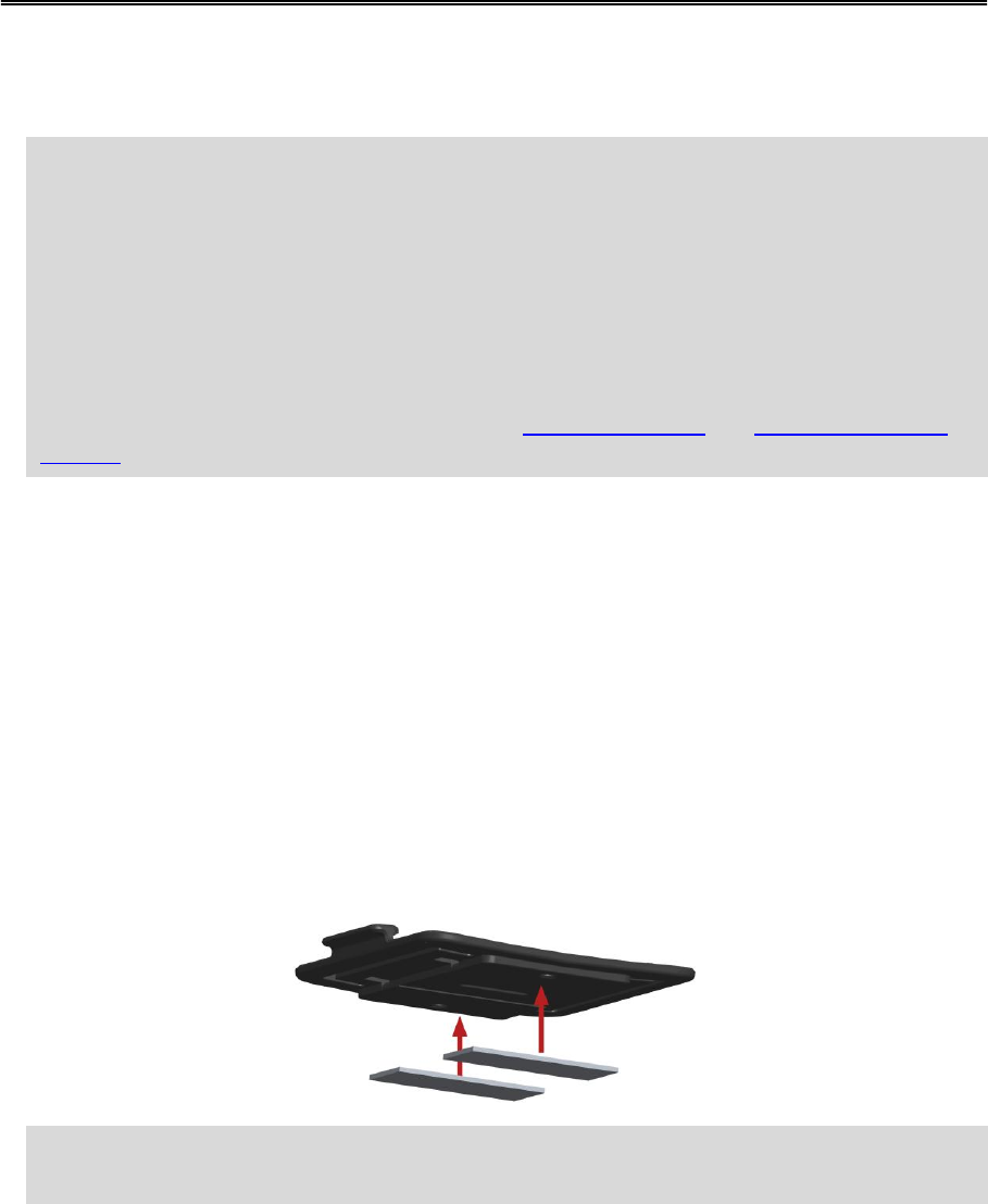
Attaching the holder using the adhesive strips
You can use the two adhesive strips to fix the LINK 530 to your vehicle. Follow the safety instruc-
tions in this document.
1. Choose a flat surface for accurate positioning of the unit.
Remember, when the LINK 530 is in the holder, it must not be obstructed by metal objects.
2. Clean the surface with the supplied cleaning tissue, so that the surface is oil free, dry and
clean.
3. Remove the protective film from one side of the strips.
4. Stick the strips to the bottom side of the holder as shown below.
Important: Use the strips only in combination with the holder. Do NOT place the strips on the
serial number sticker of the device.
5. Remove the protective film from the other side of both strips.
6. Place the holder with the adhesive strips on the prepared surface. Press it gently for a few
seconds until it sticks.
Mounting the LINK 530
19
Note: The full strength of the strips will be reached after approximately 72 hours depending
on the temperature.
7. Insert the LINK 530 into the holder. Press gently until it clicks into place.
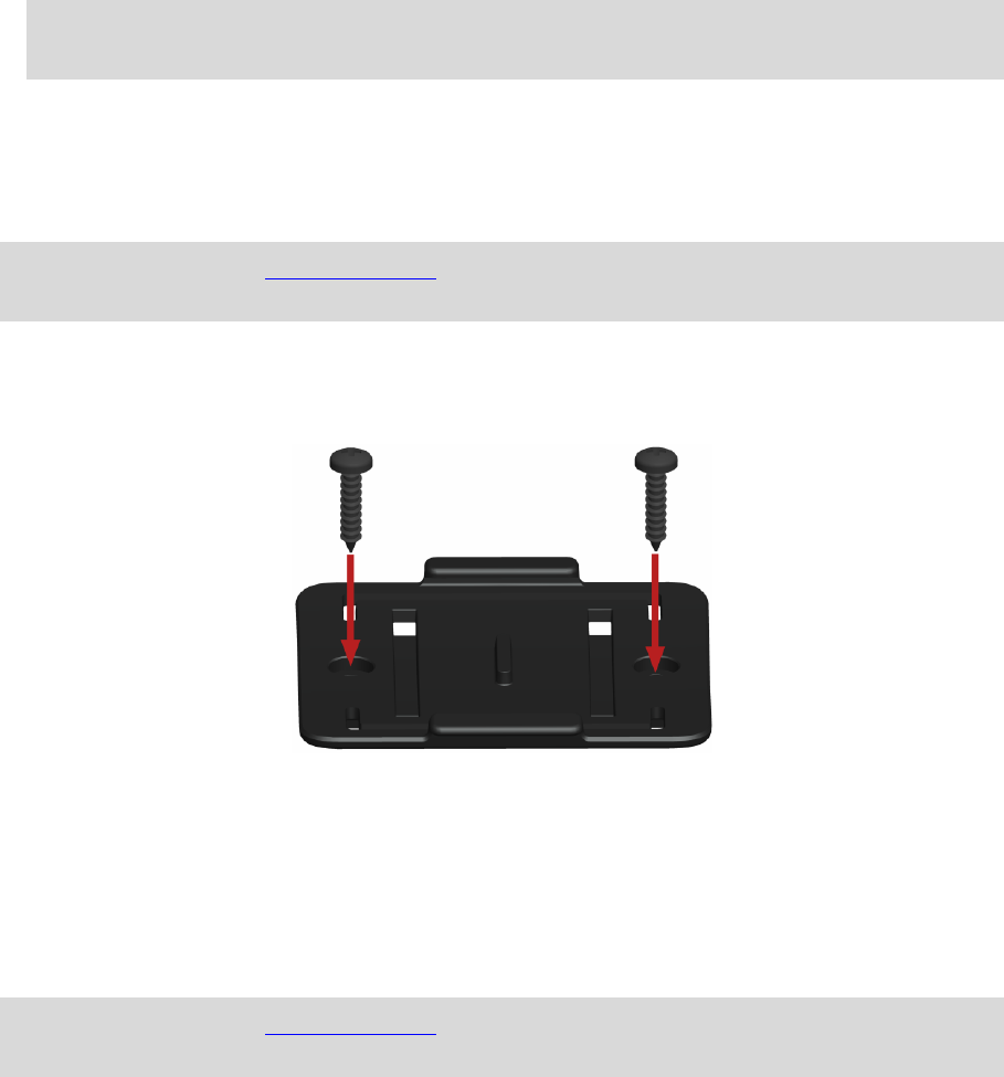
Attaching the holder using self-tapping screws
You can use two self-tapping screws to fix the holder to your vehicle.
Please refer to the list of what's in the box, to check that the self-tapping screws (3.5 x 16 mm,
1/7 x 5/8 inches) are included in your product package.
1. Choose a flat surface for the LINK 530.
Remember, when the LINK 530 is in the holder, it must not be obstructed by metal objects.
2. Insert the two screws into the corresponding holes in the holder.
3. Tighten the screws.
4. Carefully place the LINK 530 in the holder until it clicks into place.
Attaching the holder using cable ties
You can use two cable ties to fix the holder to your vehicle. Using cable ties might have an impact
on the accuracy of the driving event reporting if the device is not fixed properly.
Please refer to the list of what's in the box, to check that the cable ties (205 x 3.5 mm, 8 x 1/7
inches) are included in your product package.
1. Choose a position where the LINK 530 is not obstructed by metal objects when it is in the
holder.
2. Insert the cable ties into the corresponding holes in the holder.
3. Wrap the cable ties around the object where you want to place the holder.

20
4. Pull the cable ties through the corresponding holes of the holder and insert them in the noose
at the other end of the cable ties.
5. Pull the cable ties tight so that the holder cannot move.
6. Insert the LINK 530 into the holder. Press gently until it clicks into place.
21
In addition to the tests described below you can also test the operation of your LINK 530 using the
TomTom Telematics Diagnostic Tool with Bluetooth.
Power or Ignition test
Before testing the connection to power and to the ignition make sure you have properly carried
out the installation.
1. Please check all connections to the LINK 530 (wires, fuses etc.).
2. Turn off the ignition.
The green LED must be off and then flash on every 3 seconds.
3. Turn on the ignition.
The green LED must be on and then go off every 3 seconds. If the device is already activated,
the green LED must be on all the time.
If the LED does not perform accordingly, monitor the LEDs for diagnostics .
Mobile network reception test
For this test, you may need to move the vehicle to a location with a clear view of the sky, to make
sure that you have adequate GPS and mobile network reception.
For this test put the LINK 530 in the position where you want to fix it.
1. Turn on the ignition.
2. Monitor the yellow LED. It must be on and go off every 3 seconds.
As soon as the device has established a connection to WEBFLEET the yellow LED stays on all the
time.
If the LED keeps flashing for longer than 10 minutes, monitor the LEDs for diagnostics .
Testing operation
22
Connect your navigation device to your LINK 530 to fully enjoy the benefits of your WEBFLEET
solution.
To use a TomTom PRO navigation device in combination with the LINK 530 a corresponding
WEBFLEET subscription is required.
When you first switch on your navigation device, you are asked to connect it with the LINK 530
installed in your vehicle. You can do this immediately or at any time later by doing the following:
1. Make sure that the LINK 530 is connected to power and has a mobile network connection.
2. Switch on your navigation device.
3. Tap the screen to bring up the Main Menu.
4. Tap WORK.
You are asked to start the activation process. After you have started the activation process
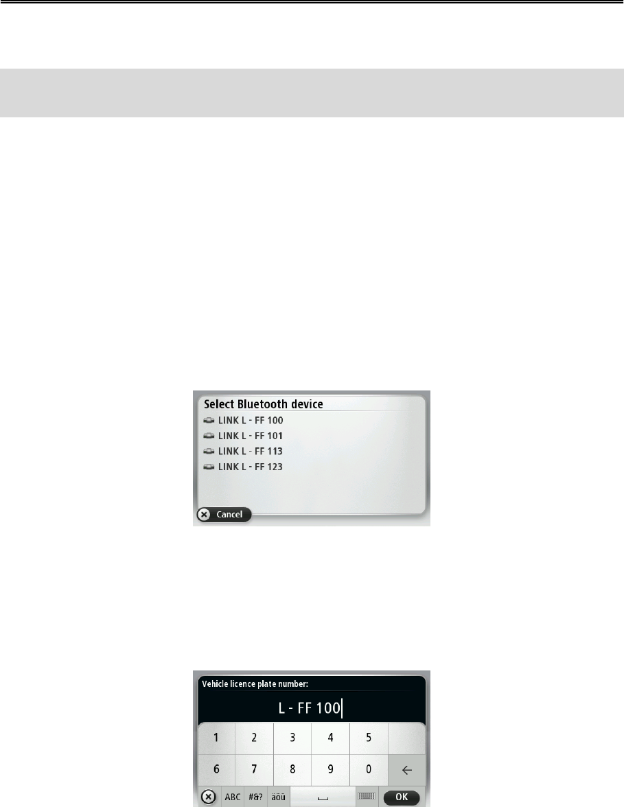
your navigation device starts searching for Bluetooth devices.
If your navigation device finds more than one Bluetooth device, it shows a list of the available
devices. Continue with step 5.
If your navigation device finds only one LINK 530, continue with step 6.
5. Select your LINK 530 from the list.
The name starts with LINK followed by the serial number of your LINK 530 or the licence plate
number of your vehicle. You can find the serial number on the outside of your LINK 530.
6. Enter the Activation Code, which you can find in your WEBFLEET contract confirmation.
Select the appropriate subscription from the list, if there are several subscriptions to choose
from. Enter a name for your LINK 530 if you are asked to do so.
7. Enter the licence plate number of the vehicle.
8. Select the appropriate vehicle type.
Connecting to PRO and WEBFLEET
23
If you select Truck or Bus, you have to enter your vehicle dimensions
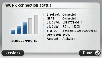
If you have properly connected the two devices, you receive a welcome message from WEBFLEET
confirming the activation. In future the connection is established automatically.
To check the connection status between the two devices, tap WORK in the Main Menu on your
navigation device, then tap Connection status.

24
Monitoring operation
You can monitor the system operation of your LINK 530 by looking at the green system LED and
referring to the table below.
For detailed diagnostics use the TomTom Telematics Diagnostic Tool. You can download the
Diagnostic Tool from the Partner Portal at business.tomtom.com/10001/areas/reseller/index.xml.
Go to Technical Support and select Activation and Diagnostics.
GREEN LED mode
OFF
Unit is in standby mode or is not connected to power.
Switch on ignition.
Check if the device is properly connected to power.
OFF and short ON
every 3sec
Ignition off.
Rapidly flashing
No operating system and/or no application available or application
failed.
Install latest firmware application using the TomTom Telematics
Firmware Update Tool.
ON and short OFF
every 3sec
Ignition on. Application is running, device is not activated.
Activate device.
ON
Application is running, device is activated.
You can monitor the connection of your LINK 530 to the mobile network and to WEBFLEET by
looking at the yellow connection LED and referring to the table below. For detailed diagnostics
always use the TomTom Telematics Diagnostics Tool.
YELLOW LED mode
OFF
Not connected - No mobile network coverage.
Check if device is connected to power. Switch on ignition.
Move the vehicle as you may be in a mobile network dead spot.
OFF and short ON
every 3sec
Not connected - Correct mobile network operator not avaialable.
Check WEBFLEET subscription for mobile network roaming support.
Move the vehicle as you may be in a mobile network dead spot.
Rapidly flashing
SIM not in place; SIM defective; Modem problem.
Use TomTom Telematics Diagnostics Tool for detailed diagnostics
and contact TomTom Telematics Customer support at busi-
ness.tomtom.com/support. Enclose the log file provided by the Di-
agnostics Tool.
ON and short OFF
Connecting. No mobile network available.
Diagnostics


26
If your LINK 530 does not operate properly or signals a system error you may need to restart or
reset the unit. Only restart or reset the LINK 530 after you have made sure you have carried out all
previously described steps without success.
Restarting your LINK
To restart your LINK 530, press the reset button with a thin pointed object until it clicks and keep it
pressed down for 1 to 2 seconds. The LINK 530 restarts immediately after releasing the button.
If restarting the device does not succeed remove the power cable from the LINK 530. Then plug it
into the power cable connector again.
Resetting your LINK to factory settings
To reset the LINK 530 to factory settings, press the reset button with a thin pointed object until it
clicks and keep it pressed for 4 to 8 seconds. The LINK 530 reboots immediately after releasing the
reset button.
Important: All information stored on the LINK 530 is deleted during a factory reset.
If resetting the device does not succeed, do the following:
1. Remove the power cable from the device.
2. Press the reset button with a thin pointed object until it clicks and keep it pressed.
3. Insert the power cable while keeping the reset button pressed for 4 to 8 seconds.
You can count the seconds with the help of the flashing of the green LED, that flashes once
per second.
The LINK 530 reboots immediately after releasing the reset button.
Resetting the LINK 530

27
Dimensions
Body: 121 x 56.5 x 21.5 mm / 4.76 x 2.22 x 0.85 inches
Body with Holder: 121 x 68 x 25.5 mm / 4.76 x 2.68 x 1.00 inches
Weight
Body: 92 g / 3.3 ounces
Holder: 14 g / 0.5 ounces
Material
Body and holder: Injection moulded plastic PC/ABS
Protection class
IP 30
Supply voltage
12 V / 24 V (min. 9 V to max. 30 V)
Current consump-
tion (average
values)
At 14 V: typically < 50 mA
At 28 V: typically < 30 mA
Standby: typically < 1 mA
During data transmission
14V < 150 mA
28V < 100 mA
Fuse protection
Operating voltage* 9 - 30 V to be fused with max. 10A
Ignition to be fused with max. 10A
* Internally fused with 2A, fuse is not resettable or replaceable, fuse must
be replaced by TomTom Telematics only
Temperature
Operation: -30 °C to +70 °C / -22 °F to +158 °F
Storage: -40 °C to +80 °C / -40 °F to +176 °F
Mobile networks
Integrated mobile network module intended for connection to one or
more of the following mobile network frequencies:
800/850/900/1800/1900/2100 MHz
GPS
Integrated GPS antenna and GPS receiver
BluetoothTM
Integrated BluetoothTM (class 2) for connection to navigation device
Ignition input
To be connected to the ignition clamp to switch on/off device together
with ignition
Digital inputs
2 inputs switchable to supply voltage
Digital output
1 output switchable to ground (open drain)
CANbus
CAN H, CAN L
GPS antenna
connector for
external GPS
antenna
(optional accesso-
ry)
SMB (male) - (antenna - female)
Supply voltage range 3.3 V
Minimum antenna gain at 3 V: 20 dB
Maximum antenna gain: 40 dB
Maximum noise rating: 1.5 dB
Technical data
28
GSM antenna
connector for
external GSM
antenna
(optional accesso-
ry)
SMB (male) - (antenna - female), for use with the GSM antenna from
TomTom Telematics only
Primary battery
3 V non-rechargeable, this device cannot be operated with this battery
29
Mounting the external GPS antenna
If you install the LINK 530 in a position where it has poor GPS reception, you need to use the
external GPS antenna accessory from TomTom Telematics, Art. no 9UKE.001.00, which comes
with an integrated magnet and an adhesive pad. The external GPS antenna from TomTom
Telematics is not part of the standard LINK 530 product package.
To check if your LINK 530 has GPS reception use the Diagnostic Tool. You can download the
Diagnostic Tool from the Partner Portal.
Important
Only use the GPS antenna from TomTom Telematics, otherwise GPS performance may be poor or
not work at all.
Tinted metallised windscreens or those with integrated filament heating may prevent good GPS
reception. In this case, place the GPS antenna in the rear window or on the outside of the vehicle.
The magnet of the antenna remains attached to the outside of the car at speeds of up to 180 km/h.
Install the GPS antenna in a position where it has a clear view of the sky and is unobstructed by
metal objects.
The GPS antenna must be placed with the adhesive pad on an oil free, dry and clean surface.
Extreme temperature changes or differences can affect the adhesive property of the pad.
To mount your external GPS antenna, do the following:
Appendix: Using external antenna
30
1. Remove the rubber cap from the GPS antenna connector.
2. Insert the plug of the GPS antenna into the GPS antenna connector on the LINK 530.
3. Prepare a smooth, clean, oil free and dry surface on the windscreen.
4. Attach the antenna to the prepared surface so that the top side has a clear view of the sky.
Either locate a smooth metal surface or use the extra adhesive pad.
Mounting the external mobile network antenna
If you install the LINK 530 in a position where it has poor reception, you need to use the external
GSM antenna accessory from TomTom Telematics, Art. no. 9KLE.001.03, which comes with an
adhesive pad. The external GSM antenna from TomTom Telematics is not part of the standard
LINK 530 product package.
Check if your LINK 530 has mobile network reception.
Important
Only use the GSM antenna from TomTom Telematics, otherwise mobile network performance
may be poor or not work at all.
Tinted metallised windscreens or those with integrated filament heating may prevent good recep-
tion. In this case, place the antenna in the rear window or on the outside of the vehicle.
Install the antenna in a place where it is unobstructed by metal objects. The antenna must be
placed with minimum 5 cm (2 inches) distance to metal objects. The top side of the antenna must
not be obstructed by metal items.
The antenna must be placed with the adhesive pad on an oil free, dry and clean surface.
Extreme temperature changes or differences can affect the adhesive property of the pad.
1. Remove the rubber cap from the GSM antenna connector.
2. Insert the plug of the mobile network antenna into the GSM antenna connector on the LINK
530.
31
3. Prepare a smooth, clean, oil free and dry surface on the windscreen.
4. Attach the antenna to the prepared surface so that the top side has clear view of the sky.
Either locate a smooth metal surface or use the extra adhesive pad.
32
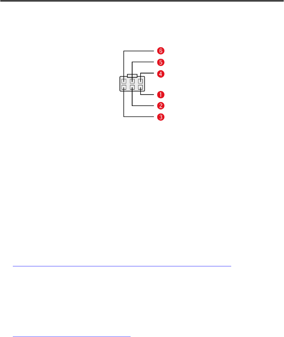
Using the IO cable, you can record inputs, for example, for keeping a digital logbook with the help
of a switch, reporting times the vehicle is idling, retrieving CANbus data etc. You can connect the
IO cable from TomTom Telematics, Art. no. 9KLE.001.02, to the IO cable connector of the
TomTom LINK 530.
CAN High (Orange/Black)
CAN Low (Orange/Brown)
GND (Brown)
IN 1 (Blue/Green)
Digital input can be used for idling reporting and logbook keeping.
IN 2 (Violet)
Digital input
OUT (Green/White)
Digital output
Using the input IN 1 for idle time reporting
Your LINK 530 can report idle times to WEBFLEET when the engine is running for longer than five
minutes and the vehicle is not moving. This requires configuration in WEBFLEET.
The input IN 1 must be connected to a signal indicating the activity of the engine, for example
alternator, engine, etc. The input IN 1 must be active when the engine is running.
Using the input IN 1 for changing the logbook mode
Your LINK 530 can report logbook-relevant information to WEBFLEET. Using the input IN 1 you
can change the logbook mode between private and business trips. This requires configuration in
WEBFLEET.
The input IN 1 must be connected to a switch indicating the trip mode. If the input IN 1 is active
the logbook mode is set to Private trip. If no or a low voltage applies to the input IN 1 the logbook
mode is set to Business trip.
Appendix: Using the IO cable
33
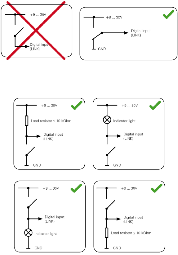
Wiring digital inputs
The digital inputs of the LINK 530 operate according to the principle of a voltage detector. Voltag-
es below 2 Volts are definitively interpreted as being low and voltages higher than 3 Volts are
definitively interpreted as being high. The maximum permissible input voltage is 30 Volts.
Low/high switching (increasing input voltage) typically occurs at 2.8 Volts. High/low switching
(decreasing input voltage) typically occurs at 2.1 Volts. The hysteresis of 0.7 Volts is to avoid rapid
switching.
Interference voltages at the digital inputs must remain below 2 Volts. In order to guarantee this,
the input wire of the connecting cable should never remain unconnected. If a digital input is not
being used, the input wire must be connected to ground (GND). To evaluate a switch, this switch
needs to be designed as a change-over switch, switching the digital input between plus and minus
(ground GND) of the vehicle electrical system voltage (+9 ... 30V).
If no change-over switch is available, an electric load for example, indicator light or resistor,
between the digital input and ground (GND) or between the digital input and the vehicle voltage
(+9 ... 30V) can offer defined levels.
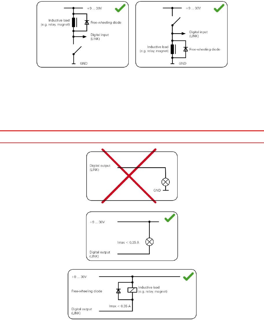
When using inductive loads, a free-wheeling diode must be used in parallel with the load.
34
Wiring the digital output
The digital output OUT of the LINK 530 is an open drain output linking to ground. The connected
load must be connected between vehicle voltage and OUT. Loads requiring more than 0.35 A
must be controlled with relays. If the load requires more than the maximum output voltage use a
12 V/24 V relay, depending on the operating voltage.
Caution: Do not switch safety relevant vehicle functions.

35
Important Safety Notices and Warnings
Global Positioning System (GPS) and Global Navigation Satellite System (GLONASS)
The Global Positioning System (GPS) and Global Navigation Satellite System (GLONASS) systems
are satellite-based systems that provide location and timing information around the globe. GPS is
operated and controlled under the sole responsibility of the Government of the United States of
America, who are responsible for its availability and accuracy. GLONASS is operated and con-
trolled under the sole responsibility of the Government of Russia, who are responsible for its
availability and accuracy. Any changes in GPS or GLONASS availability and accuracy, or in envi-
ronmental conditions, may impact the operation of this device. TomTom does not accept any
liability for the availability and accuracy of GPS or GLONASS.
Use with care
Use of TomTom products while driving still means that you need to drive with due care and
attention.
Aircraft and hospitals
Use of devices with an antenna is prohibited on most aircraft, in many hospitals and in many other
locations. This device must not be used in these environments.
Safety messages
Please read and take note of the following important safety advice:
Check your tyre pressures regularly.
Service your vehicle regularly.
Medication can affect your riding or driving ability.
Always use seat belts if available.
Don’t drink and drive.
Most accidents happen less than 5 km from home.
Obey the rules of the road.
Always use your turn indicators.
Every 2 hours, take a break for at least 10 minutes.
Keep your seat belts on.
Keep a safe distance from the vehicle in front.
Before setting off on a motorbike, fasten your helmet correctly.
When riding a motorbike, always wear protective clothing and equipment.
When riding a motorbike, be extra vigilant and always ride defensively.
How TomTom uses your information
Information regarding the use of personal information can be found at tomtom.com/privacy.
Addendum
36
Battery and Environmental information
This product uses a non rechargeable Lithium battery that is not user accessible or user replacea-
ble. Do not open the case or (attempt to) remove the battery. Substances in the product and/or
battery may be harmful to the environment or your health if disposed of improperly. The battery
contained in the product must be recycled or disposed of properly according to the local laws and
regulations and always kept separate from household waste.
CE marking
The unit described in this document is in accordance with the official European directives. A copy
of the declaration of conformity can be provided on request. This equipment complies with the
essential requirements of EU Directive 99/5/EC. The GPRS-modem integrated in this product has
been pre-certified separately and is marked with CE0168.
R&TTE directive
Hereby, TomTom declares that TomTom products and accessories are in compliance with the
essential requirements and other relevant provisions of the EU Directive 1999/5/EC. The declara-
tion of conformity can be found here: tomtom.com/legal.
WEEE directive
The wheelie bin symbol on the product or its packaging indicates that this product shall not be
treated as household waste. In line with EU Directive 2002/96/EC for waste electrical and electronic
equipment (WEEE), this electrical product must not be disposed of as unsorted municipal waste.
Please dispose of this product by returning it to the point of sale or to your local municipal collec-
tion point for recycling. By doing this you will help conserve the environment.
FCC information for the user
37
THE DEVICE COMPLIES WITH PART 15 OF THE FCC RULES
Federal Communications Commission (FCC) Statement
This equipment radiates radio frequency energy and if not used properly - that is, in strict accord-
ance with the instructions in this manual - may cause interference to radio communications and
television reception.
Operation is subject to the following two conditions: (1) this device may not cause harmful inter-
ference and (2) this device must accept any interference, including interference that may cause
undesired operation of the device.
This device has been tested and found to comply with the limits for a Class B digital device,
pursuant to part 15 of the FCC rules. These limits are designed to provide reasonable protection
against harmful interference in a residential installation. This equipment generates, uses and can
radiate radio frequency energy and, if not installed and used in accordance with the instructions,
may cause harmful interference to radio communications. However, there is no guarantee that
interference will not occur in a particular installation. If this equipment does cause harmful inter-
ference to radio or television reception, which can be determined by turning the equipment off
and on, the user is encouraged to try to correct the interference by one or more of the following
measures:
Reorient or relocate the receiving antenna.
Increase the separation between the equipment and receiver.
Connect the equipment into an outlet on a circuit different from that to which the receiver
is connected.
Consult the dealer or an experienced radio/TV technician for help.
Changes or modifications not expressly approved by the party responsible for compliance could
void the user's authority to operate the equipment.
Important
This equipment was tested for FCC compliance under conditions that included the use of shielded
cables and connectors between it and the peripherals. It is important that you use shielded cable
and connectors to reduce the possibility of causing radio and television interference. Shielded
cables, suitable for the product range, can be obtained from an authorized dealer. If the user
modifies the equipment or its peripherals in any way, and these modifications are not approved by
TomTom, the FCC may withdraw the user’s right to operate the equipment. For customers in the
USA, the following booklet prepared by the Federal Communications Commission may be of help:
"How to Identify and Resolve Radio-TV Interference Problems". This booklet is available from the
US Government Printing Office, Washington, DC 20402. Stock No 004-000-00345-4.
FCC ID: S4LLINK530
IC ID: 5767A-LINK530
FCC RF Radiation Exposure Statement
The transmitters within this device must not be co-located or operating in conjunction with any
other antenna or transmitter.
38
Exposure limits
This device complies with radiation exposure limits set forth for an uncontrolled environment. In
order to avoid the possibility of exceeding the radio frequency exposure limits, human proximity
to the antenna shall not be less than 20cm (8 inches) during normal operation.
Specific Absorption Rate (SAR) compliance
THIS WIRELESS DEVICE MODEL MEETS GOVERNMENT REQUIREMENTS FOR EXPOSURE TO
RADIO WAVES WHEN USED AS DIRECTED IN THIS SECTION
This device is a radio transmitter and receiver. It is designed and manufactured not to exceed the
emission limits for exposure to radio frequency (RF) energy set by the Council of the European
Union and the Federal Communications Commission of the U.S. Government. These limits are
part of comprehensive guidelines and establish permitted levels of RF energy for the general
population.
The SAR limit set by Fthe CC/ IC is 1.6W/kg averaged over 1 gram of tissue for the body (4.0 W/kg
averaged over 10 grams of tissue for the extremities - hands, wrists, ankles and feet). The SAR
limit recommended by The Council of the European Union is 2.0W/kg averaged over 10 grams of
tissue for the body (4.0 W/kg averaged over 10 grams of tissue for the extremities - hands, wrists,
ankles and feet). Tests for SAR are conducted using standard operating positions specified by
the FCC/IC/EU council with the device transmitting at its highest certified power level in all tested
frequency bands.
Before a wireless device model is available for sale to the public, it must be tested and certified to
the FCC, IC, and The Council of the European Union that it does not exceed the limit established
by the government-adopted requirement for safe exposure under the recommendations of the
International Commission on Non-Ionizing Radiation Protection (ICNIRP). The tests are performed
in positions and locations as required by the FCC, IC, and The Council of the European Union for
each model.
To maintain compliance with FCC, IC, and EU RF exposure guidelines, when you carry a TomTom
device with an integrated mobile data module keep the device at least 20cm (8 inches) from your
body when the device is transmitting. If you use an accessory not supplied by TomTom when you
carry the device, verify that the accessory does not contain metal and keep the device at least
20cm (8 inches) from your body when the device is transmitting.
Responsible party in North America
TomTom, Inc., 150 Baker Avenue Extension, Concord, MA 01742
Tel: 866 486-6866 option 1 (1-866-4-TomTom)
Customer support contact
US: 1-866-459-3499
Emissions information for Canada
Operation is subject to the following two conditions:
This device may not cause interference.
This device must accept any interference, including interference that may cause undesired
operation of the device.

39
Operation is subject to the condition that this device does not cause harmful interference.
This Class B digital apparatus complies with Canadian ICES-003. CAN ICES-3(B)/NMB-3(B).
IMPORTANT NOTE
IC Radiation Exposure Statement:
This equipment complies with IC RSS-102 radiation exposure limits set forth for an uncon-
trolled environment.
This device and its antenna(s) must not be co-located or operating in conjunction with any
other antenna or transmitter.
This equipment should be installed and operated with minimum distance 20cm between
the radiator & your body.
Pacemakers
Pacemaker manufacturers recommend that a minimum of 15cm (6 inches) be maintained between
a handheld wireless device and a pacemaker to avoid potential interference with the pacemaker.
These recommendations are consistent with independent research and recommendations by
Wireless Technology Research.
Guidelines for people with pacemakers
You should ALWAYS keep the device more than 15cm (6 inches) from your pacemaker.
You should not carry the device in a breast pocket.
Other medical devices
Please consult your physician or the manufacturer of the medical device, to determine if the
operation of your wireless product may interfere with the medical device.
Mobile networks
Devices that contain a mobile network module are intended for connection to one or more of the
following mobile network frequencies:
800/850/900/1800/1900/2100 MHz
A-tick
N14644
This product displays the A-tick to show it complies with relevant Australian regulations.
Warning for Australia
The user needs to switch off the device when exposed to areas with potentially explosive atmos-
pheres such as petrol stations, chemical storage depots and blasting operations.
Customer support contact
Australia: 1300 135 604

40
New Zealand: 0800 450 973
C-tick
N14644
This product displays the C-tick to show it complies with relevant Australian regulations.
Notice for New Zealand
This product displays R-NZ to show it complies with relevant New Zealand regulations.
Model names
L0530
Copyright notices
© 2014 TomTom. All rights reserved. TomTom and the "two hands" logo are registered trade-
marks of TomTom N.V. or one of its subsidiaries. Please see tomtom.com/legal for limited war-
ranty and end user licence agreements applying to this product.