Toshiba Icc Multiprotocol Ethernet Interface Asd G9Eth Users Manual V2.100 User's
2014-12-13
: Toshiba Toshiba-Icc-Multiprotocol-Ethernet-Interface-Asd-G9Eth-Users-Manual-130813 toshiba-icc-multiprotocol-ethernet-interface-asd-g9eth-users-manual-130813 toshiba pdf
Open the PDF directly: View PDF ![]() .
.
Page Count: 106 [warning: Documents this large are best viewed by clicking the View PDF Link!]
ICC
INDUSTRIAL CONTROL COMMUNICATIONS, INC.
Madison Office Houston Office
1600 Aspen Commons, Suite 210 12300 Dundee Court, Suite 212
Middleton, WI USA 53562-4720 Cypress, TX USA 77429-8364
Tel: [608] 831-1255 Fax: [608] 831-2045
http://www.iccdesigns.com Printed in U.S.A
ASD INTERFACE SERIES
ICC
INDUSTRIAL CONTROL COMMUNICATIONS, INC.
ASD-G9ETH
MULTIPROTOCOL ETHERNET INTERFACE FOR
TOSHIBA G9 / VFAS1 ADJUSTABLE SPEED DRIVES
August 2008
ICC #10639-2.100-000

1
ICC
ASD-G9ETH Multiprotocol Ethernet Interface
User's Manual
Part Number 10639-2.100-000
Printed in U.S.A.
©2007-2008 Industrial Control Communications, Inc.
All rights reserved
NOTICE TO USERS
Industrial Control Communications, Inc. reserves the right to make changes
and improvements to its products without providing notice.
Industrial Control Communications, Inc. shall not be liable for technical or
editorial omissions or mistakes in this manual, nor shall it be liable for incidental
or consequential damages resulting from the use of information contained in
this manual.
INDUSTRIAL CONTROL COMMUNICATIONS, INC.’S PRODUCTS ARE NOT
AUTHORIZED FOR USE AS CRITICAL COMPONENTS IN LIFE-SUPPORT
DEVICES OR SYSTEMS. Life-support devices or systems are devices or
systems intended to sustain life, and whose failure to perform, when properly
used in accordance with instructions for use provided in the labeling and user's
manual, can be reasonably expected to result in significant injury.
No complex software or hardware system is perfect. Bugs may always be
present in a system of any size. In order to prevent danger to life or property, it
is the responsibility of the system designer to incorporate redundant protective
mechanisms appropriate to the risk involved.
This user’s manual may not cover all of the variations of interface applications,
nor may it provide information on every possible contingency concerning
installation, programming, operation, or maintenance.
The contents of this user’s manual shall not become a part of or modify any
prior agreement, commitment, or relationship between the customer and
Industrial Control Communications, Inc. The sales contract contains the entire
obligation of Industrial Control Communications, Inc. The warranty contained in
the contract between the parties is the sole warranty of Industrial Control
Communications, Inc., and any statements contained herein do not create new
warranties or modify the existing warranty.
Any electrical or mechanical modifications to this equipment without prior
written consent of Industrial Control Communications, Inc. will void all
warranties and may void any UL/cUL listing or other safety certifications.
Unauthorized modifications may also result in equipment damage or personal
injury.

2
ICC
Usage Precautions
• Please use the interface only when the ambient temperature of the
environment into which the unit is installed is within the following
specified temperature limits:
Operation: -10 ∼ +50°C (+14 ∼ +122°F)
Storage: -40 ∼ +85°C (-40 ∼ +185°F)
• Avoid installation locations that may be subjected to large shocks or
vibrations.
• Avoid installation locations that may be subjected to rapid changes in
temperature or humidity.
Operating Environment
• Proper ground connections are vital for both safety and signal reliability
reasons. Ensure that all electrical equipment is properly grounded.
• Route all communication cables separate from high-voltage or noise-
emitting cabling (such as ASD input/output power wiring).
Installation and Wiring
• Do not touch charged parts of the drive such as the terminal block
while the drive’s CHARGE lamp is lit. A charge will still be present in
the drive’s internal electrolytic capacitors, and therefore touching these
areas may result in an electrical shock. Always turn the drive’s input
power supply OFF, and wait at least 5 minutes after the CHARGE lamp
has gone out before connecting communication cables.
• For further drive-specific precaution, safety and installation information,
please refer to the appropriate documentation supplied with your drive.
• Internal ASD EEPROMs have a limited life span of write cycles.
Observe all precautions contained in this manual and your ASD
manual regarding which drive registers safely may and may not be
repetitively written to.
ASD Connection
s

3
ICC
TABLE OF CONTENTS
1. Introduction ...................................................................................6
2. Features .........................................................................................7
3. Precautions and Specifications ..................................................9
3.1 Installation Precautions......................................................................... 9
3.2 Maintenance Precautions ................................................................... 10
3.3 Inspection ........................................................................................... 11
3.4 Storage............................................................................................... 11
3.5 Warranty............................................................................................. 11
3.6 Disposal.............................................................................................. 11
3.7 Environmental Specifications.............................................................. 12
4. Interface Board Overview ..........................................................13
5. Installation ...................................................................................14
5.1 Installation Procedure......................................................................... 14
5.2 Installing Multiple Option Cards .......................................................... 16
6. LED Indicators.............................................................................17
6.1 Front Panel......................................................................................... 17
6.2 Ethernet Jack...................................................................................... 18
7. Configuring the IP Address .......................................................19
7.1 Via the Finder Utility............................................................................ 19
7.2 Via the Drive’s Keypad ....................................................................... 20
7.3 Via the Web Page............................................................................... 20
8. Using the ICC Finder Utility .......................................................21
9. Parameter Numbering ................................................................22
10. Embedded Web Server...........................................................24
10.1 Overview............................................................................................. 24
10.2 Authentication..................................................................................... 25
10.3 Page Select Tabs ............................................................................... 26
10.4 Monitor Tab ........................................................................................ 26
10.4.1 Information Window ................................................................... 26
10.4.2 Parameter Group Selection List................................................. 26
10.4.3 Parameter Subgroup Selection List ........................................... 27
10.4.4 Parameter List............................................................................ 28

4
ICC
10.4.5 Parameter List Filter ...................................................................29
10.4.6 Radix Selection...........................................................................29
10.5 Profinet Tab.........................................................................................30
10.5.1 Information Window....................................................................30
10.5.2 I/O Data Configuration Arrays ....................................................31
10.5.3 Device Identification and Configuration ......................................32
10.5.4 Submitting Changes ...................................................................32
10.6 BACnet Tab.........................................................................................33
10.6.1 Information Window....................................................................33
10.6.2 Device Identifiers........................................................................34
10.6.3 Submitting Changes ...................................................................34
10.7 Config Tab...........................................................................................35
10.7.1 Information Window....................................................................35
10.7.2 Drive Configuration Parameter Write Selection ..........................36
10.7.3 Authentication Configuration.......................................................36
10.7.4 Timeout Configuration ................................................................37
10.7.5 IP Address Configuration............................................................38
10.7.6 MAC Address Configuration .......................................................38
10.7.7 Submitting Changes ...................................................................38
10.8 EtherNet/IP Tab ..................................................................................40
10.8.1 Information Window....................................................................40
10.8.2 Device Identification ...................................................................41
10.8.3 Run/Idle Flag Behavior...............................................................41
10.8.4 Class 1 (I/O) Data Configuration Arrays .....................................42
10.8.5 Submitting Changes ...................................................................43
10.9 Alarm Tab............................................................................................44
10.9.1 Information Window....................................................................44
10.9.2 Email Configuration ....................................................................45
10.9.3 Alarm Configuration....................................................................46
10.9.4 Submitting Changes ...................................................................48
10.10 Modbus Tab....................................................................................49
10.10.1 Information Window....................................................................49
10.10.2 Register Remap Configuration ...................................................49
10.10.3 Submitting Changes ...................................................................51
11. Interacting With the Filesystem.............................................52
11.1 Initiating FTP via the Finder Utility.......................................................53
11.2 Using FTP with Windows Explorer ......................................................54
11.3 Using FTP with a Windows Command Prompt....................................56
11.4 Using FTP with Core FTP LE..............................................................58
12. Loading New Application Firmware .....................................60

5
ICC
13. Protocol-Specific Information ...............................................61
13.1 Modbus/TCP....................................................................................... 61
13.1.1 Overview.................................................................................... 61
13.1.2 Coil & Discrete Input Mappings.................................................. 62
13.2 EtherNet/IP......................................................................................... 64
13.2.1 Overview.................................................................................... 64
13.2.2 ODVA AC/DC Drive Profile........................................................ 65
13.2.3 ControlLogix Examples: Setup................................................... 68
13.2.4 ControlLogix Example: I/O Messaging....................................... 70
13.2.5 Explicit Messaging Tag Reference............................................. 73
13.2.6 ControlLogix Example: Read a Register Block .......................... 75
13.2.7 ControlLogix Example: Read a Single Register ......................... 82
13.2.8 ControlLogix Example: Multiple MSG Instructions ..................... 82
13.2.9 ControlLogix Example: Reading and Writing.............................. 83
13.3 PCCC ................................................................................................. 85
13.3.1 Tag Reference ........................................................................... 85
13.3.2 SLC-5/05 Example: Read a Register Block ............................... 86
13.3.3 SLC-5/05 Example: Read a Single Register .............................. 92
13.3.4 SLC-5/05 Example: Multiple MSG Instructions .......................... 92
13.3.5 SLC-5/05 Example: Reading and Writing................................... 93
13.4 BACnet ............................................................................................... 95
13.4.1 Overview.................................................................................... 95
13.4.2 Protocol Implementation Conformance Statement..................... 95
13.4.3 Supported Objects ..................................................................... 99
13.4.4 Supported Object Details......................................................... 101
13.5 Profinet IO ........................................................................................ 104

6
ICC
1. Introduction
Congratulations on your purchase of the ICC Multiprotocol Ethernet Interface
for the Toshiba G9, H9, Q9 and VFAS1 families of Adjustable Speed Drives
(ASDs). This interface allows information to be transferred seamlessly between
the drive and several different Ethernet-based fieldbus networks with minimal
configuration requirements. The interface installs directly into the drive
enclosure and presents a standard 10/100BaseT Ethernet port for connection
to the Ethernet network. In addition to the supported fieldbus protocols, the
interface also hosts an embedded web server, which provides access to all
drive information via a standard web browser for remote monitoring,
configuration and control.
Before using the interface, please familiarize yourself with the product and be
sure to thoroughly read the instructions and precautions contained in this
manual. In addition, please make sure that this instruction manual is delivered
to the end user of the interface and ASD, and keep this instruction manual in a
safe place for future reference or unit inspection.
For the latest information, support software and firmware releases, please visit
http://www.iccdesigns.com.
Before continuing, please take a moment to ensure that you have received all
materials shipped with your kit. These items are:
• Ethernet interface in plastic housing
• Documentation CD-ROM
Note that different interface firmware versions may provide varying levels of
support for the various protocols. When using this manual, therefore, always
keep in mind that the firmware version running on your interface must match
this manual’s respective revision in order for all documented aspects to apply.
This manual will primarily be concerned with the interface board’s hardware
specifications, installation, wiring, configuration and operational characteristics.
For more advanced ASD application-level information, please contact Toshiba’s
ASD Marketing Department for copies of available application notes.
To maximize the abilities of your new ASD interface, a working familiarity with
this manual will be required. This manual has been prepared for the interface
installer, user, and maintenance personnel. With this in mind, use this manual
to develop a system familiarity before attempting to install or operate the
interface or ASD.

7
ICC
2. Features
Ethernet Port
IEEE 802.3 10/100BaseT Ethernet compliant. Shielded RJ45 connector
accepts standard CAT5-type 8-conductor unshielded twisted-pair (UTP) patch
cables. Supports multiple simultaneous protocols.
Supported Protocols
The interface currently provides server support for the following fieldbus
protocols:
• Modbus TCP
• EtherNet/IP
• PCCC
• BACnet/IP
• Profinet IO
Note that use of Profinet IO is mutually exclusive of the other supported
protocols. In order to use Profinet IO, a separate application firmware file must
be loaded into the interface (refer to section 12).
Macromedia® Flash-Enabled Embedded Web Server
Interface configuration and real-time drive parameter monitoring & control are
provided via an embedded web server. The interface’s web server feature
provides direct data access and control via standard web browsers such as
Microsoft Internet Explorer and Mozilla Firefox. The latest version of
Macromedia Flash Player browser plug-in is required. Refer to section 9.
XML Configuration File Upload/Download
All interface configuration files are stored in the unit’s internal filesystem in XML
format. These files can be transferred to/from a PC via the FTP protocol, which
provides the capability for PC-based file backup and easy configuration copying
to multiple units. Configuration files can also be viewed and edited via standard
text editors, XML editors and web browsers. Refer to section 11.
Email-Based Alarm Notifications
Up to 20 configurable alarm conditions can be programmed into the interface.
Value, logical comparison and time-based conditions can be provided for the
interface to autonomously monitor any available drive register. When an alarm
condition is triggered, a notification email can be sent to up to four destination
email addresses. Refer to section 10.9.
Network Timeout Action
A configurable network timeout action can be programmed that allows
parameters to have their own unique "fail-safe" conditions in the event of a
network interruption. Refer to section 10.7.4.

8
ICC
Field-Upgradeable
As new firmware becomes available, the interface can be upgraded in the field
by the end-user. Refer to section 12 for more information.
EtherNet/IP Data Access Options
The EtherNet/IP protocol provides access to inverter data via explicit
messaging, user-defined I/O assembly instances, and the ODVA AC/DC drive
profile. Refer to section 13.2 for more information.

9
ICC
3. Precautions and Specifications
Rotating shafts and electrical equipment can be hazardous.
Installation, operation, and maintenance of the ASD and interface
board shall be performed by Qualified Personnel only.
Qualified Personnel shall be:
• Familiar with the construction and function of the ASD and
interface board, the equipment being driven, and the hazards
involved.
• Trained and authorized to safely clear faults, ground and tag
circuits, energize and de-energize circuits in accordance with
established safety practices.
• Trained in the proper care and use of protective equipment in
accordance with established safety practices.
Installation of ASD systems and associated interface boards
should conform to all applicable National Electrical Code (NEC)
Requirements For Electrical Installations, all regulations of the
Occupational Safety and Health Administration, and any other
applicable national, regional, or industry codes and standards.
DO NOT install, operate, perform maintenance, or dispose of this
equipment until you have read and understood all of the following
product warnings and user directions. Failure to do so may result
in equipment damage, operator injury, or death.
3.1 Installation Precautions
• Use lockout/tagout procedures on the branch circuit
disconnect before installing the interface board into the ASD.
• Avoid installation in areas where vibration, heat, humidity,
dust, metal particles, or high levels of electrical noise (EMI)
are present.
• Do not install the ASD or interface board where it may be
exposed to flammable chemicals or gasses, water, solvents,
or other fluids.
• Where applicable, always ground the interface board
appropriately to prevent electrical shock to personnel and to
help reduce electrical noise. The ASD’s input, output, and
control power cables are to be run separately from the
interface board’s associated cables.
Note: Conduit is not an acceptable ground.

10
ICC
• Turn the power on only after attaching the front cover.
• Follow all warnings and precautions and do not exceed
equipment ratings.
• The ASD maintains a residual charge for a while after turning
supply power off. After turning supply power off, wait at least
ten minutes before servicing the ASD or interface board.
Ensure that the Charge LED is off prior to beginning
installation.
• For further ASD-specific precaution, safety and installation
information, please refer to the applicable Adjustable Speed
Drive Operation Manual supplied with your ASD.
3.2 Maintenance Precautions
• Use lockout/tagout procedures on the branch circuit
disconnect before servicing the ASD or installed interface
board.
• The ASD maintains a residual charge for a while after turning
supply power off. After turning supply power off, wait at least
ten minutes before servicing the ASD or interface board.
Ensure that the Charge LED is off prior to beginning
maintenance.
• Do Not attempt to disassemble, modify, or repair the interface
board. Contact your ICC or Toshiba sales representative for
repair or service information.
• Turn the power on only after attaching the front cover and Do
Not remove the front cover of the ASD when the power is on.
• If the ASD should emit smoke or an unusual odor or sound,
turn the power off immediately.
• The ASD heat sink and discharge resistors may become
extremely hot to the touch. Allow the unit to cool before
coming into contact or performing service on the ASD or
interface board.
• The system should be inspected periodically for damaged or
improperly functioning parts, cleanliness, and to determine
that all connectors are tightened securely.

11
ICC
3.3 Inspection
Upon receipt, perform the following checks:
• Inspect the unit for shipping damage.
• Check for loose, broken, damaged or missing parts.
Report any discrepancies to your ICC or Toshiba sales representative.
3.4 Storage
• Store the device in a well ventilated location (in its shipping carton, if
possible).
• Avoid storage locations with extreme temperatures, high humidity, dust, or
metal particles.
3.5 Warranty
This communication interface is covered under warranty by ICC, Inc. for a
period of 12 months from the date of installation, but not to exceed 18 months
from the date of shipment from the factory. For further warranty or service
information, please contact Industrial Control Communications, Inc. or your
local distributor.
3.6 Disposal
• Contact the local or state environmental agency in your area for details on
the proper disposal of electrical components and packaging.
• Do not dispose of the unit via incineration.

12
ICC
3.7 Environmental Specifications
Item Specification
Operating Environment Indoors, less than 1000m above sea level, do not
expose to direct sunlight or corrosive / explosive
gasses
Operating Temperature -10 ∼ +50°C (+14 ∼ +122°F)
Storage Temperature -40 ∼ +85°C (-40 ∼ +185°F)
Relative Humidity 20% ∼ 90% (without condensation)
Vibration 5.9m/s2 {0.6G} or less (10 ∼ 55Hz)
Grounding Non-isolated, referenced to ASD control power
ground
Cooling Method Self-cooled
Communication Speed 10/100BaseT auto sensing
The ASD-G9ETH interface is lead-free / RoHS-compliant.
13
ICC
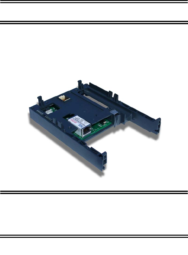
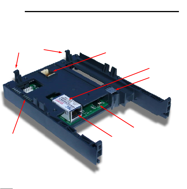
4. Interface Board Overview
Mounting Tabs Drive Connector
LEDs
Ground Plate
Configuration Switches
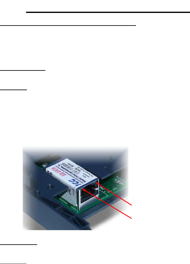
Shielded RJ45 Ethernet Jack
MAC ID
Note: The configuration switches are used for factory test only, and should
remain in the OFF (up) position at all times.

14
ICC
5. Installation
This interface card has been designed for quick and simple installation. The
card is connected to the drive's control board via a 30-pin rectangular
connector, and is mechanically supported via an integral housing that
seamlessly mates with the drive’s enclosure. The only tool required for
installation is a flat-blade screwdriver.
Before opening the drive, please observe all safety precautions as outlined on
the drive's front cover and in the operation manual.
5.1 Installation Procedure
1. CAUTION! Verify that all input power sources to the drive
have been turned OFF and are locked and tagged out.
2. DANGER! Wait at least 5 minutes for the drive’s
electrolytic capacitors to discharge before proceeding to the next step. Do
not touch any internal parts with power applied to the drive, or for at
least 5 minutes after power to the drive has been removed. A hazard
exists temporarily for electrical shock even if the source power has
been removed. Verify that the CHARGE LED has gone out before
continuing the installation process.
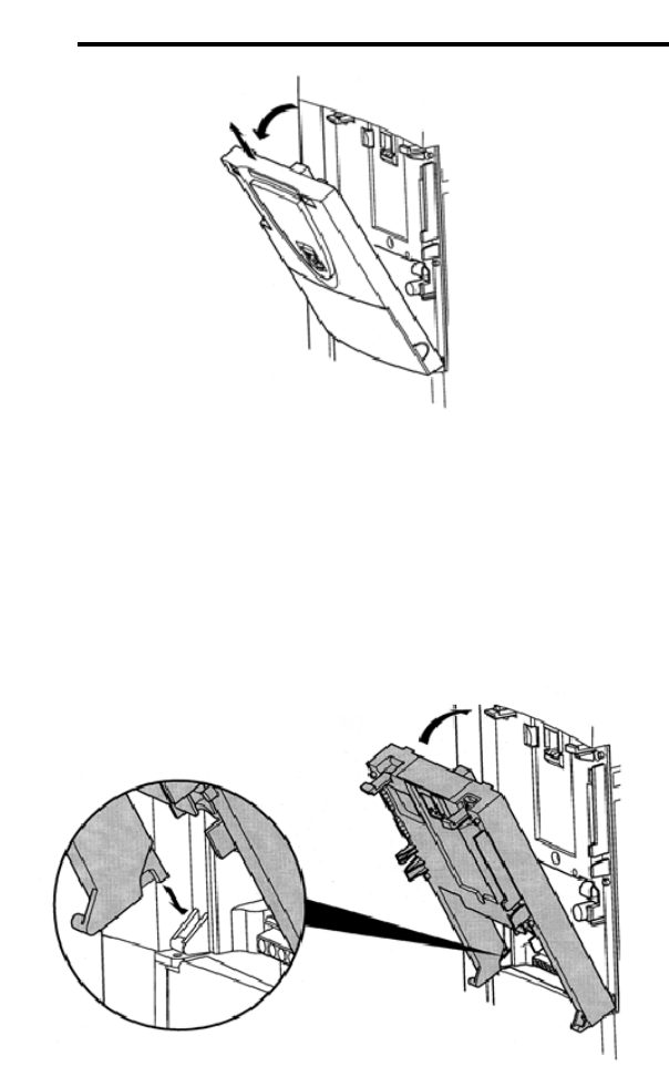
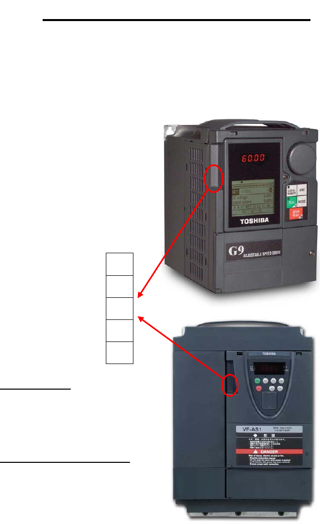
3. Remove the drive’s display panel and front cover by inserting a flat-blade
screwdriver into each of the two mounting tab access openings at the top
of the front cover and depressing each of the mounting tabs (Figure 1).
Rotate the top of the font cover outward and remove the cover (Figure 2).
Figure 1: Releasing the Drive's Front Cover
15
ICC
Figure 2: Removing the Drive's Front Cover
4. Install the interface card into the drive by inserting the tabs on the lower
legs of the interface housing into the corresponding slots on the drive’s
enclosure. Rotate the interface housing up and press it onto the drive
enclosure’s mounting tabs, depressing firmly until the housing snaps into
place (Figure 3). Double-check that the plastic bosses located on the left
and right side of the drive enclosure are properly inserted into the
corresponding recesses on the back of the interface housing, and that the
interface housing is overall secure and flush with the drive enclosure.
Figure 3: Installing the Interface Card
5. Reinstall the drive’s front cover by inserting the tabs on the bottom part of
the front cover into the corresponding slots on the interface housing.
Rotate the front cover up and press it onto the interface housing’s
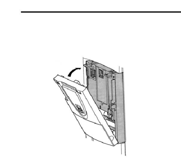
16
ICC
mounting tabs, depressing firmly until the front cover snaps into place
(Figure 4). Double-check that the plastic bosses located on the left and
right side of the interface housing are properly inserted into the
corresponding recesses on the back of the front cover, and that the front
cover is overall secure and flush with the interface housing.
Figure 4: Reinstalling the Drive's Front Cover
6. Insert the network cable into the Ethernet jack. Ensure that the connector
is fully seated into the jack, and route the cable such that it is located well
away from any electrical noise sources, such as drive’s input power or
motor wiring. Also take care to route the cable away from any sharp edges
or positions where it may be pinched.
7. Turn the power source to the drive ON, and verify that it functions properly.
If the drive does not appear to power up, or does not function properly,
immediately turn power OFF. Repeat steps 1 and 2 to remove all power
from the drive. Then, verify all connections. Contact ICC or your local
Toshiba representative for assistance if the problem persists.
5.2 Installing Multiple Option Cards
When this communication interface is installed into a drive in conjunction with
an I/O option card, the I/O option card must be installed first (adjacent to the
drive’s enclosure), and the communication interface must be installed last
(adjacent to the drive’s front panel).
17
ICC
6. LED Indicators
6.1 Front Panel
The interface board has 5 bicolor (red/green) LEDs that are visible through the
ASD’s front cover (labeled 2.1 through 2.5).
Interface Status: Normally solid
green during operation. If a fatal error
occurs, this LED will flash a red error
code. The number of sequential blinks
(followed by 3s of OFF time) indicates
the error code.
EIP Module Status / Reserved:
When the multi-protocol firmware
image (with EtherNet/IP support) is
loaded, this LED conforms to the
prescribed “module status LED”
behavior as dictated in the
EtherNet/IP specification, Volume 2,
Chapter 9. When the Profinet IO
firmware image is loaded, this LED is
reserved, and therefore always OFF.
Interface Status 2.1
EIP Module Status /
Reserved 2.2
EIP Network Status /
Profinet Cnxn Status 2.3
Ethernet Activity 2.4
Heartbeat 2.5
18
ICC
EIP Network Status / Profinet IO Connection Status: When the multi-
protocol firmware image (with EtherNet/IP support) is loaded, this LED
conforms to the prescribed “network status LED” behavior as dictated in the
EtherNet/IP specification, Volume 2, Chapter 9. When the Profinet IO firmware
image is loaded, this LED is on solid green when the controller has established
a link with the interface board and is communicating with it.
Ethernet Activity: Blinks green briefly when network packets are sent or
received.
Heartbeat: Blinks green to indicate communication between the interface card
and the drive. Contact ICC technical support if a blinking red error code is
observed.
6.2 Ethernet Jack
The Ethernet jack also contains two embedded LEDs.
Reserved
Ethernet Link
Ethernet Link: This amber LED is lit whenever a viable Ethernet network is
connected to the port.
Reserved: This green LED is currently unused and is therefore always OFF.
19
ICC
7. Configuring the IP Address
Before you can access the interface from your web browser or begin using it as
a part of your automation network, you must know its IP address. The interface
comes from the factory configured to obtain an IP address dynamically
(DHCP/BOOTP). You can determine the interface’s current IP address using
the discovery software included on the CD provided with the interface, or
available from the ICC homepage at http://www.iccdesigns.com.
7.1 Via the Finder Utility
To configure the interface to use a static IP address:
1. Connect the interface to your network and apply power to the ASD. When
the interface boots up, it will attempt to obtain an IP address from a DHCP
server or, failing that, will fallback to either the last static IP address
assigned, or a default static IP address of 192.168.16.102 if no static IP
address has yet been assigned.
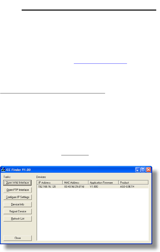
2. To determine the initial IP address of your interface, start the ICC
FINDER.EXE discovery utility.
3. The discovery utility scans the network for ICC devices and then lists each
device’s IP Address, MAC Address, Firmware Version and Product ID.
Identify your device by its MAC address (printed on a label on the top of
the Ethernet network jack). Refer to Figure 5.
Figure 5: ICC Finder Discovery Utility
4. To change the IP address, select the device in the list of detected devices
and click the Configure IP Settings button.

20
ICC
5. In the dialog that appears, select Manually configure network settings.
6. Enter the desired IP Address, Subnet Mask, Default Gateway and case-
sensitive system password (default is “icc”) in the appropriate boxes, then
click Apply.
7. A popup dialog box will prompt you to reboot. Click Reboot Device.
Rebooting may require 30s or more to complete. When the device status
indicates “Ready”, click Close.
8. The discovery utility will automatically rescan the network. Confirm that the
new IP address has been accepted by the device.
7.2 Via the Drive’s Keypad
This section applies to G9 (drive control board firmware V203R5 and later) and
H9 (drive control board firmware V204R4) drives only.
The interface card’s IP Address, Subnet Mask, Default Gateway, and
DHCP/Static IP mode can be viewed and modified via the drive’s keypad by
navigating to Program…Communications…Ethernet Settings. Additionally, the
interface card’s unique MAC ID can be viewed (but not modified) in this screen.
Note that these parameter values are read by the interface card only during
initial boot-up. Therefore, be sure to power cycle the drive whenever any of
these values are changed to allow the changes to take effect.
7.3 Via the Web Page
Once an initial IP address has been assigned to the device and the
configuration web page can be accessed, the IP address-related parameters
can also be modified via the web page. Refer to section 10.7.5.

21
ICC
8. Using the ICC Finder Utility
The “ICC Finder” utility is a simple Windows PC program (just a single .exe file,
no installations, DLL’s etc.), which when executed discovers all ICC
communication interfaces on the current Ethernet subnet, regardless of
whether or not their network parameters are currently compatible with the
subnet upon which they reside. Refer to Figure 5 on page 19.
In order for the Finder application to discover devices, certain UDP Ethernet
traffic must be allowed in and out of the computer, and firewall applications
(such as Windows Firewall) are often configured to block such traffic by default.
If the Finder is unable to discover any devices on the current subnet, be sure to
check the computer’s firewall settings during troubleshooting, and add an
exception to the firewall configuration if necessary.
All discovered devices can be organized in ascending or descending order by
clicking on the desired sort header (IP Address, MAC Address, Application
Firmware or Product). The buttons on the left side of the window perform the
following actions:
Open Web Interface: Opens a web browser page of the selected device.
Refer to section 9.
Open FTP Interface: Opens the computer’s default FTP application, which
could be either Windows Explorer, a web browser, or a 3rd-party FTP program
(whatever the computer/operating system is configured for by default). This
allows you to interact directly with the unit’s on-board flash filesystem, enabling
you to drag and drop files to/from the unit and upload new firmware. Refer to
section 11.
Configure IP Settings: Allows configuration of whether the device will use
static IP parameters or will obtain its IP parameters via DHCP. Refer to section
7 for more information.
Device Info: Opens a dialog box containing relevant device information.
Reboot Device: Opens a dialog box which prompts for a password to reboot
the interface. Enter the case-sensitive system password (default is “icc”), then
click Reboot. The reboot cycle has completed when the displayed status
changes from “Rebooting” to “Ready” (note that this may require 30s or more to
complete.) Clicking Close will then close the dialog box and cause the
discovery utility to automatically rescan the network.
Refresh List: Causes the discovery utility to rescan the network.
Close: Closes the discovery utility.

22
ICC
9. Parameter Numbering
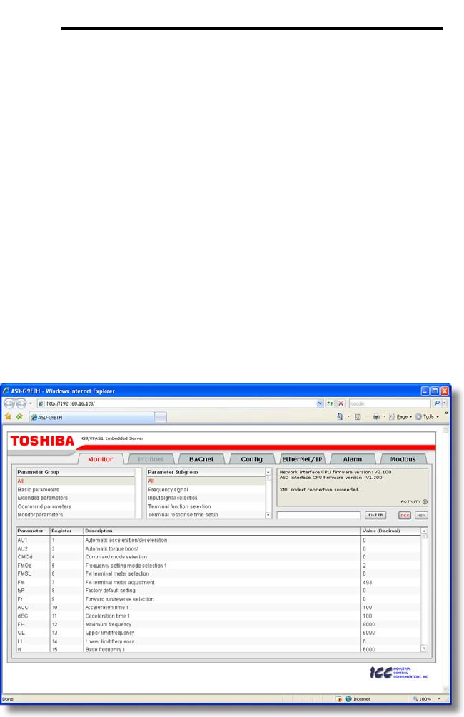
Inspection of the Toshiba ASD user’s manual reveals that the ASD’s
parameters are organized as hexadecimal numbers ranging from F000 to
FFFF. These parameters are made accessible to the interface board as
“registers”, and are numerically remapped to present a more natural interface to
the communications user. There are 1500 total registers available via the
interface board, and their mappings are as shown in Table 1.
Table 1: ASD Parameter-to-Register Mapping
Hexadecimal ASD
Parameter Numbers… …Map to Decimal Register
Numbers
F000 - F999 1 - 1000
FA00 - FA99 1001 - 1100
FB00 - FB99 1101 - 1200
FC00 - FC99 1201 - 1300
FD00 - FD99 1301 - 1400
FE00 - FE99 1401 - 1500
This mapping is easier to understand if one just uses the interface's web page
as a guide (refer to Figure 6 and section 10.4.4). The "parameter” numbers
(ASD references) and "register” numbers (network references) for all available
parameters are shown in the first two columns. Commanding the drive over the
network therefore entails writing to registers 1007 (option board command) and
1008 (option board frequency command), which correspond to ASD parameters
FA06 and FA07, respectively.
Figure 6: Web Page Register Assignment Reference
To avoid confusion, when this user’s manual uses the term “parameter”, it will
be referring to the ASD’s hexadecimal number as documented in the ASD

23
ICC
user’s manual. Similarly, when this user’s manual uses the term “register”, it
will be referring to the decimal number as it is exposed to the network interface.
Note that although 1500 total registers are available in the register space, not
all of those registers have corresponding parameters that exist in the drive. In
other words, if a read from or write to a register that does not correspond to an
existing drive parameter takes place, the read/write will be successful, but the
data will have no meaning. This feature is beneficial in situations where the
accessing of non-contiguous registers can be made more efficient by accessing
an all-inclusive block of registers (some of which correspond to drive
parameters and some of which do not), while only manipulating those in your
local programming that are known to exist.
24
ICC
10. Embedded Web Server
10.1 Overview
The interface contains an embedded web server (also known as an HTTP
server), which allows users to access the drive’s internal data in a graphical
manner with web browsers such as Microsoft Internet Explorer or Mozilla
Firefox. In this way, the drive can be monitored, configured and controlled from
across the room or from across the globe.
In order to view the interface’s web page, the free Adobe (formerly
Macromedia) Flash Player browser plug-in is required. If the plug-in is not
already installed on your computer, then your browser will automatically be
redirected to the appropriate Adobe download web site when you initially
attempt to access the interface’s web page. Alternatively, the plug-in can be
downloaded directly by going to http://www.adobe.com, and choosing the “get
Adobe Flash Player” link. Always ensure that you have the latest version of the
Flash Player installed: if some aspect of the web page does not appear to be
displayed properly, installing the latest Flash Player update usually resolves the
problem.
Figure 7: Embedded Web Server
To access an interface’s embedded web server, either use the finder utility
(refer to section 8) and select the “Open Web Interface” button when the target
25
ICC
unit is highlighted, or just directly enter the target unit’s IP address into the
address (URL) field of your web browser. Refer to Figure 7 for a representative
screenshot of the web server interface.
In order to access the web server and view the parameter values, destination
TCP ports 80 and 2000 must be accessible from the client computer. If an
“XML socket connection failed” error message is displayed in the information
window, and no parameter values are shown, this is typically indicative of port
2000 being blocked by a firewall or Ethernet router situated between the client
computer and the interface card.
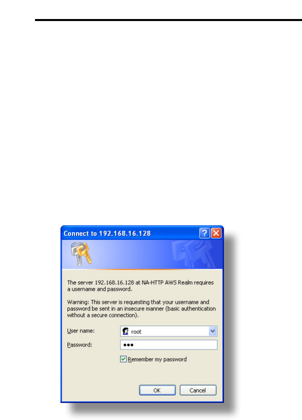
10.2 Authentication
For security, the interface requires valid user authentication whenever the web
page is accessed. The authentication request will appear as a browser popup
box that will request entry of a user name and password. Refer to Figure 8.
Figure 8: Web Server Authentication
The factory-default user name is “root”, and the password is “icc”. Note that the
username and password are case-sensitive, and that once authenticated, the
authentication will remain in effect from that point until all browser windows are
closed. The authentication credentials can also be changed from their default
settings (refer to section 10.7.3.)
26
ICC
10.3 Page Select Tabs
The web interface is subdivided into several different “tabs” of associated
information, much the same as how folders in a filing cabinet are arranged.
Refer to Figure 9. To change tabs, just click on the tab you wish to view. The
title of the currently-selected tab is red. Note that because different protocols
are supported by the interface with different firmware images, not all tabs may
be accessible with the firmware image currently loaded. The titles of tabs that
are not accessible are grayed-out, and clicking them has no effect.
Figure 9: Page Select Tabs
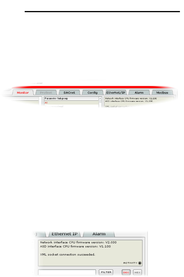
10.4 Monitor Tab
10.4.1 Information Window
Figure 10 shows the Information Window, which is located in the upper-right
hand corner of the monitor tab. This window displays various informational
messages regarding the status of the interface card or web browser session.
There is also an “activity” indicator located in the lower-right hand corner of the
Information Window, which blinks periodically to show the status of data
communication between the web browser and the interface card. If you do not
observe the activity indicator blink at all for several seconds or more, it is
possible that the web browser may have lost contact to the web server due to a
drive reset or a network problem: to reestablish communications, select
“refresh” on your web browser.
Figure 10: Monitor Tab Information Window
10.4.2 Parameter Group Selection List
The Parameter Group Selection List is located in the upper-left hand corner of
the Monitor Tab. Refer to Figure 11. When a parameter group is selected, the
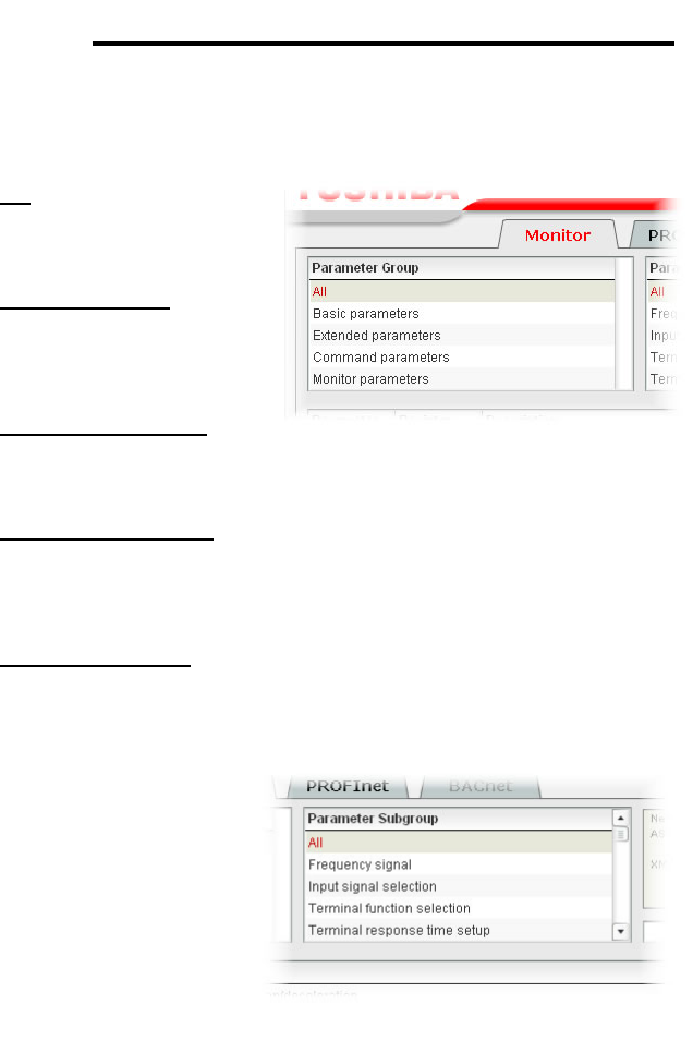
27
ICC
parameter subgroups (if any) contained in that parameter group are displayed
in the Parameter Subgroup Selection List (refer to section 10.4.3), and the
corresponding parameters are displayed in the Parameter List (refer to section
10.4.4). The following parameter groups are available:
All: All parameters are
available (configuration,
command and monitor
parameters).
Basic Parameters: Only
the configuration
parameters most commonly
used for drive setup are
available.
Extended Parameters: All
other configuration
parameters that are not
“basic parameters” are available.
Command Parameters: Only drive command parameters are available. Note
that although all parameters associated with drive control are available in this
selection, only those parameters that are identified as being for the “internal
option board” can be used to actually control the drive via the option board: all
other drive command parameters can only be monitored via the option board.
Monitor Parameters: Only drive monitor parameters are available.
10.4.3 Parameter Subgroup Selection List
Subgroups can be used
to further filter the
parameters of a group
that are to be displayed
in the Parameter List.
Refer to Figure 12.
If the group currently
selected in the
Parameter Group
Selection List (refer to
section 0) has subgroups
available, then choosing
the desired subgroup will further filter the parameters that are displayed in the
Parameter List. If the currently-selected group does not have any available
subgroups, then only the “All” subgroup will be shown, and all parameters in
that group will be shown in the Parameter List.
Figure 11: Parameter Group Selection List
Figure 12: Parameter Subgroup Selection List
28
ICC
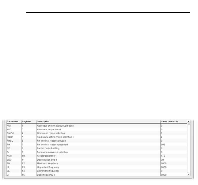
10.4.4 Parameter List
The bottom half of the Monitor tab contains the parameter list (refer to Figure
13). The parameters that are displayed in the list at any given time depend on
the group/subgroup selected, as well as whether or not any filters have been
applied (refer to section 10.4.5).
The first two columns of the Parameter List show the parameter name and the
register number that provides access to that parameter, and were discussed in
detail in section 9. The third column contains the parameter descriptions, which
are used by the filter function. The last column performs two functions: it
displays the current value of the parameter, and also allows changing the
parameter’s value by clicking on the number in the value column and entering
the new value.
Figure 13: Parameter List
Some items to keep in mind when interacting with the Parameter List are:
• When entering new parameter values, be sure that the number being
entered is appropriate for the currently-selected radix (refer to section
10.4.6): for example, an entered value of “1000” in hexadecimal is equal to
4096 in decimal.
• If desired, the column widths can be changed by dragging the vertical bars
that separate the header row’s cells to a different position.
• If you begin changing a parameter value and then decide to abandon the
change, pressing the ESC key on your keyboard will abandon the change
and redisplay the current parameter value.
• When editing a parameter value, clicking someplace off the entry cell is
equivalent to hitting the ENTER key.

29
ICC
10.4.5 Parameter List Filter
A filter function provides Parameter List search capabilities. To use the filter
function, simply type a word or portion of a word into the filter entry box and
then click the “filter” button. Refer to Figure 14.
The filter will then display only
those parameters currently
available in the Parameter List
that satisfy the search criteria.
For example, to find all monitor
parameters that contain some
derivative of the word “volt” (such
as “voltage” or “volts”), select the
“Monitor Parameters” group, the “All” subgroup, and then enter “volt” in the filter
entry box.
Once a filter has been entered, it will continue to be applied to all information
normally displayed in the Parameter List for as long as the filter term is left in
the filter entry box. Continuing the previous example where we filtered on the
root term “volt” in the monitor parameters, we can then easily apply this filter to
all parameters (configuration, command or monitor) simply by selecting the “All”
parameter group. The Parameter List will now display all configuration,
command or monitor parameters that contain the root term “volt”.
To remove the filter, delete any characters contained in the filter entry box and
then click the “filter” button.
10.4.6 Radix Selection
Figure 15 shows the radix selection buttons.
These selection buttons allow changing the
Parameter List “value” column data display
and entry radix between decimal and
hexadecimal formats.
When “DEC” is selected, the “value” column
heading will be “Value (Decimal)”, current parameter values will be displayed in
decimal, and values to be written to parameters must be entered in decimal
format. For example, to change the drive’s frequency command to 40.00Hz,
enter the decimal value 4000.
Similarly, when “HEX” is selected, the “value” column heading will be “Value
(Hexadecimal)”, current parameter values will be displayed in hexadecimal, and
values to be written to parameters must be entered in hexadecimal format. For
example, to turn on bits #15, #14 and #10 in the drive’s command word, enter
the hexadecimal number C400.
Figure 14: Parameter List Filter
Figure 15: Radix Selection
30
ICC
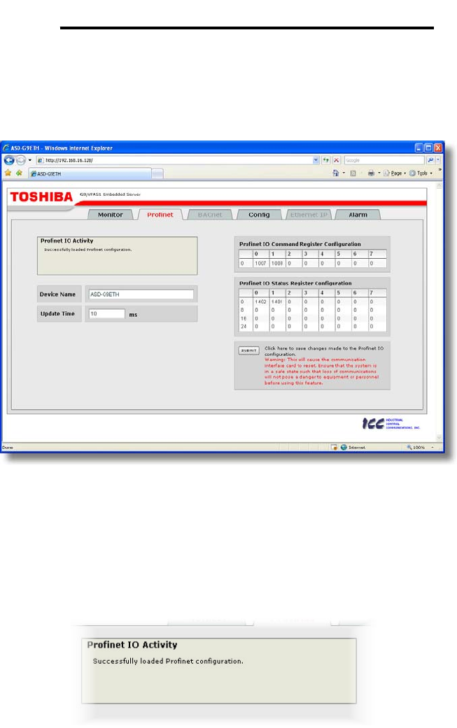
10.5 Profinet Tab
This section is only applicable when the Profinet firmware is loaded onto the
interface card. The Profinet tab provides for the configuration of the device on
a Profinet network. Refer to Figure 16.
Figure 16: Profinet Tab
10.5.1 Information Window
Figure 17 shows the Information Window, which is located in the upper-left
hand corner of the Profinet tab. This window displays various informational
messages regarding the status of the Profinet configuration (loading or
submitting).
Figure 17: Profinet Tab Information Window
31
ICC
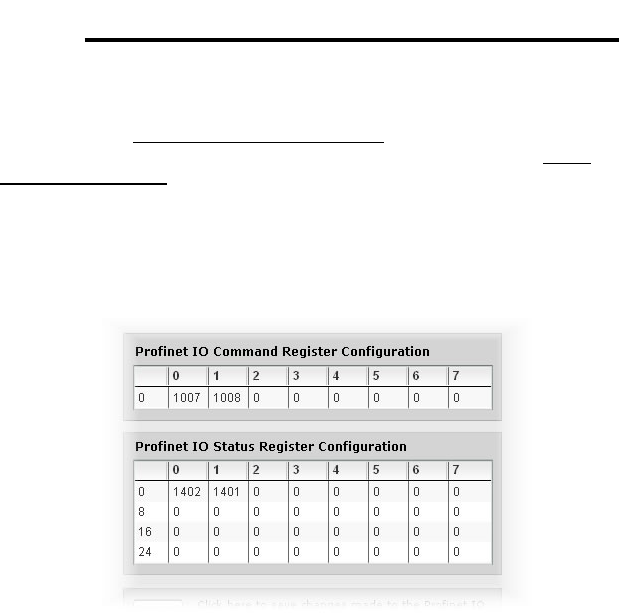
10.5.2 I/O Data Configuration Arrays
The I/O data configuration arrays consist of two separate elements (refer to
Figure 18.) The command register configuration defines the structure of the
command data sent from the Profinet controller to the drive, and the status
register configuration defines the structure of the status data sent from the drive
back to the controller. These arrays allow the creation of custom-built I/O data.
Up to 8 command registers can be sent to the drive, and up to 32 status
registers can be sent back to the controller. Each box in an array is capable of
containing a register number. Because all drive registers are 16-bit data
elements, each box therefore represents two bytes of input or output data.
Figure 18: I/O Data Configuration
The command register array locations are numbered 0-7, and traverse from left
to right. The status register array locations are numbered 0-31, and traverse
from left to right across each row, and then increment to the left-most position
on the next row. Clicking on a box in an array allows the user to enter a
register number that will be referenced at that location when data is either
received from or sent to the controller. A value of 0 indicates that no register is
referenced at that location, which will cause corresponding command data to be
ignored and status data to be a default value of 0.
As an example, looking at the default configuration shown in Figure 18, we can
see that each array contains two defined registers. Therefore, up to 4
“meaningful” bytes of data can be both received and sent (the qualifier
“meaningful” is used here because the module currently selected by the
controller may require larger input and/or output data sizes, but all
unreferenced command data will be ignored, and all unreferenced status data
will contain dummy “0” values). The first word (two bytes) of command data will
be written to register 1007 (command 1) and the second word will be written to
register 1008 (frequency command). Similarly, the first word of status data will
contain the value of register 1402 (status 1) and the second word will contain
the value of register 1401 (output frequency).
32
ICC
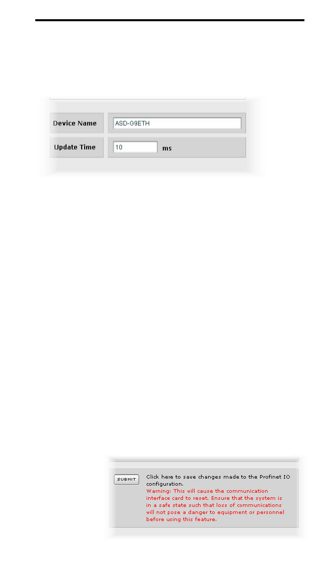
10.5.3 Device Identification and Configuration
There are several identification and configuration items available for setting
various characteristics of the Profinet device. These items are shown in Figure
19 and are explained in further detail below.
Figure 19: Profinet Device Identification and Configuration
A Profinet device’s name (station name) must be unique across the entire
Profinet network because it is used by controllers to uniquely identify Profinet
devices. The Device Name text entry box is used to configure this unique
device identifier on every drive.
The Update Time field is a configuration item which changes the frequency
with which command and status data updates take place internally in the
device. This setting is not related to the frequency with which data
communications take place on the Ethernet network. This time setting is a 32-
bit value adjustable in 1ms increments. Typically, this value should not need to
be changed from its default value of 10ms.
10.5.4 Submitting Changes
Whenever any of the Profinet configuration elements (I/O array configuration,
Device Name, etc.) have been changed, the “submit” button located in the
lower right-hand portion of the web page must be clicked in order to write these
settings to the interface card’s filesystem.
Note that because these configuration elements are read from the filesystem
only when the interface card boots up, the act of submitting configuration
changes will also reset
the interface card.
Please allow 30
seconds for the
interface card to reboot,
at which time it will then
be operating with the
recently-submitted
configuration. Refer to
Figure 20.
Figure 20: Submit Profinet Changes
33
ICC
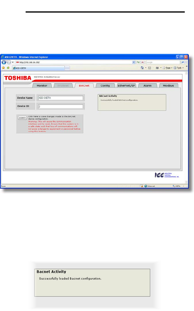
10.6 BACnet Tab
The BACnet tab provides for the configuration of the device on a BACnet/IP
network. Refer to Figure 21.
Figure 21: BACnet Tab
10.6.1 Information Window
Figure 22 shows the Information Window, which is located in the upper-right
hand corner of the BACnet tab. This window displays various informational
messages regarding the status of the BACnet configuration (loading or
submitting).
Figure 22: BACnet Tab Information Window
34
ICC
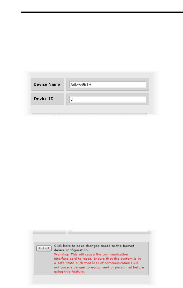
10.6.2 Device Identifiers
A BACnet device’s name and ID (the Object_Name and Object_Identifier
properties, respectively, of the Device Object) must be unique across the entire
BACnet network because they are used to uniquely identify BACnet devices.
The text entry boxes shown in Figure 23 are used to configure these unique
device identifiers on every drive.
Figure 23: BACnet Device Identifiers
10.6.3 Submitting Changes
Whenever either of the BACnet configuration elements (Device Name or
Device ID) has been changed, the “submit” button located in the left-hand
portion of the web page must be clicked in order to write these settings to the
interface card’s filesystem.
Note that because these configuration elements are read from the filesystem
only when the interface card boots up, the act of submitting configuration
changes will also reset the interface card. Please allow 30 seconds for the
interface card to reboot, at which time it will then be operating with the recently-
submitted configuration. Refer to Figure 24.
Figure 24: Submit BACnet Changes
35
ICC
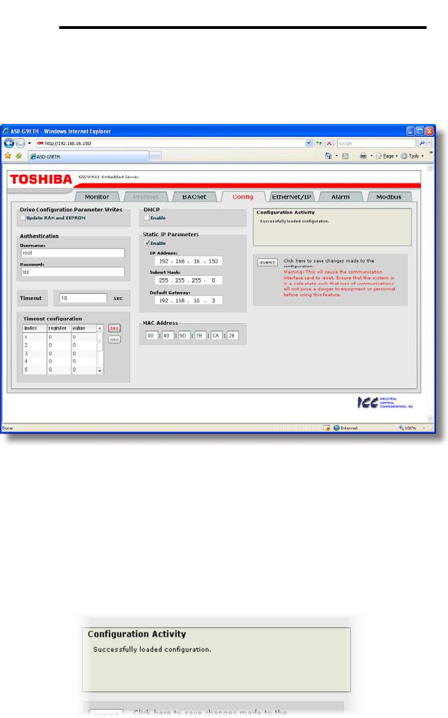
10.7 Config Tab
The Config tab provides access to various configuration items. Refer to Figure
25.
Figure 25: Config Tab
10.7.1 Information Window
Figure 26 shows the Information Window, which is located in the upper-right
hand corner of the Config tab. This window displays various informational
messages regarding the status of the configuration parameters (loading or
submitting).
Figure 26: Config Tab Information Window
36
ICC
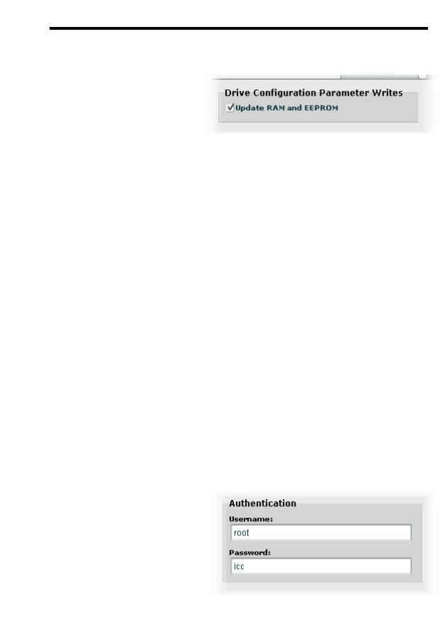
10.7.2 Drive Configuration Parameter Write Selection
Figure 27 shows the check box
selection that determines whether
drive configuration parameters
(registers 1..1000) will be written
only to the drive’s RAM, or to both
the drive’s RAM and EEPROM
when they are changed via the
interface card.
If written to RAM only, then parameter value changes will be lost when the drive
is power cycled or otherwise reset. If written to both RAM and EEPROM, then
parameter value changes will be retained. When enabling writes to EEPROM,
be sure to always observe Toshiba’s restrictions on the number of times a
configuration parameter may be written to EEPROM before possible EEPROM
damage occurs.
This selection affects all configuration parameters, and applies regardless of
the interface card mechanism used to modify the parameters (control protocol
data write, modification via the web page “monitor” tab, timeout configuration
setting etc.)
Note that ASD Interface CPU firmware version V1.100 or later is required for
this feature to be supported (refer to Figure 10 on page 26 for how to determine
the ASD interface CPU version.)
10.7.3 Authentication Configuration
Figure 28 shows the entry boxes
used to modify the authentication
credentials. The case-sensitive
username and password can
contain letters (“a”..”z” and “A”..”Z”)
and numbers (“0”..”9”), and can
each be up to 80 characters in
length.
Be sure to make a note of the new
settings whenever these credentials
are changed, as they must be entered whenever the web page is accessed, an
FTP session is initiated, or when a configuration change is performed via the
Finder utility. Contact ICC for assistance if you have forgotten your customized
credentials.
Figure 27: RAM Only or RAM/EEPROM
Write Selection
Figure 28: Authentication
Configuration
37
ICC
10.7.4 Timeout Configuration
The interface can be configured to
perform a specific set of actions
when network communications are
lost. Support for this feature varies
depending on the protocol: refer to
the protocol-specific section of this
manual for further information.
There are two separate elements
that comprise the timeout
configuration (refer to Figure 29):
• The timeout time
• The timeout configuration array
The timeout time is a floating-point
number which allows adjustment
down to 1/100th of a second (0.01 second increments). This time setting is
used by certain protocols in order to determine abnormal loss-of-
communications conditions and, optionally, to trigger a timeout processing
event. The default timeout time is 10s.
The timeout configuration array allows up to 10 register/value pairs to be
designated by the user. When a timeout event is triggered by a protocol, the
timeout configuration array indexes are parsed. If the “register” field for an
index is set to 0, then this index is “disabled” and therefore ignored. If, on the
other hand, the “register” field is non-zero, then the value contained in the
“value” field is automatically written to the designated register. This flexible
mechanism allows up to 10 designated drive registers to have their own unique
“fail-safe” conditions in the event of a network interruption.
For example, Figure 29 shows a timeout time of 10s, and one timeout entry
assignment. If a protocol that makes use of timeout processing triggers a
timeout event, then a value of 5000 will automatically be written to drive register
1008 (the frequency command). Provided the drive has a valid “run” command
and is currently configured to use the network frequency command as its
master frequency command, it will ramp to 50.00Hz.
If timeout/failsafe processing is not desired, just set the “register” fields for all
indexes to 0 (disabled). This is the default condition.
“DEC” and “HEX” selection buttons are also available, and allow changing the
“value” column data display and entry radix between decimal and hexadecimal
formats, respectively. These buttons provide the ability to interact with the
various drive registers in their most natural radix (e.g. a hexadecimal command
word vs. a decimal frequency command value).
Figure 29: Timeout Configuration
38
ICC
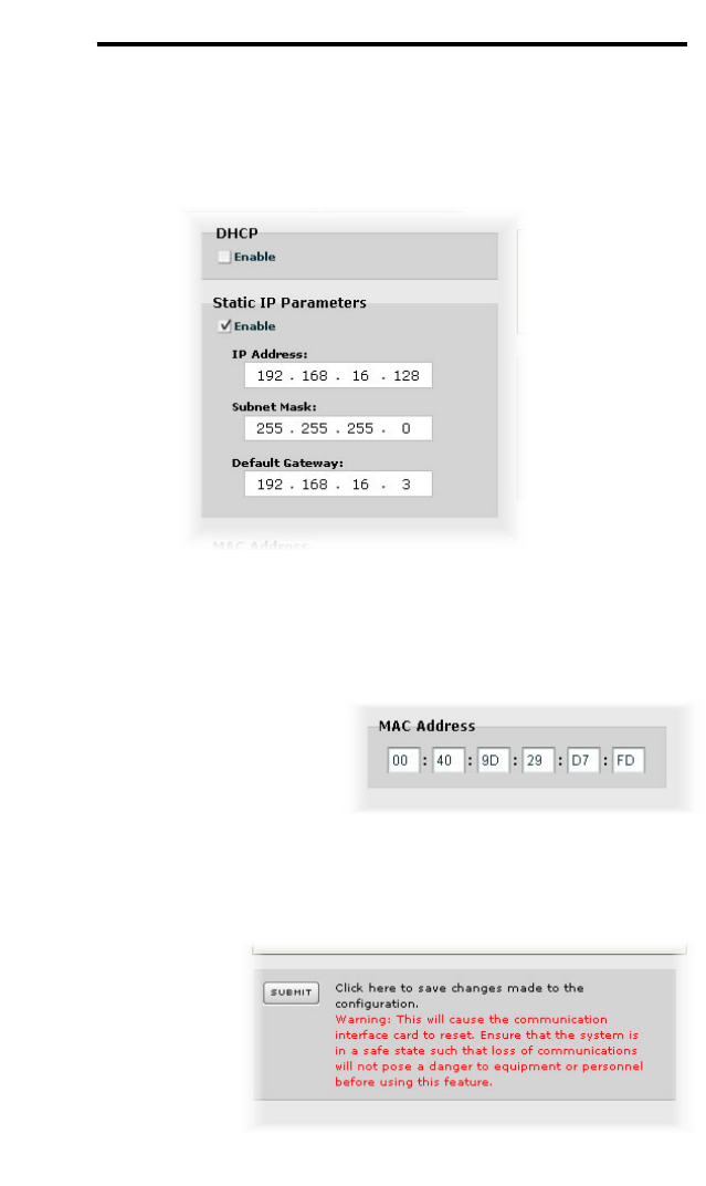
10.7.5 IP Address Configuration
Figure 30 shows the configuration items used to modify the IP address-related
parameters. Modification of these settings is consistent with the technique
used with the Finder utility (refer to section 7.1).
Figure 30: IP Address Configuration
10.7.6 MAC Address Configuration
Figure 31 shows the entry boxes
that are used to view and/or modify
the unique MAC address of the
interface. The MAC address should
not be changed without first
consulting ICC Technical Support.
10.7.7 Submitting Changes
Whenever any of the
configuration elements
has been changed, the
“submit” button located
in the right-hand
portion of the web page
must be clicked in
order to write these
settings to the interface
card’s filesystem.
Figure 31: MAC Address Config
Figure 32: Submit Configuration Changes

39
ICC
Note that because these configuration elements are read from the filesystem
only when the interface card boots up, the act of submitting configuration
changes will also reset the interface card. Please allow 30 seconds for the
interface card to reboot, at which time it will then be operating with the recently-
submitted configuration. Refer to Figure 32.
40
ICC
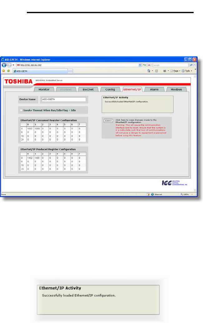
10.8 EtherNet/IP Tab
The EtherNet/IP tab provides access to configuration items related to
communication on an EtherNet/IP network. Refer to Figure 33.
Figure 33: EtherNet/IP Tab
10.8.1 Information Window
Figure 34 shows the Information Window, which is located in the upper-right
hand corner of the EtherNet/IP tab. This window displays various informational
messages regarding the status of the EtherNet/IP configuration parameters
(loading or submitting).
Figure 34: EtherNet/IP Tab Information Window
41
ICC
10.8.2 Device Identification
A text entry box is available which allows customization of the device’s name
for identification on the EtherNet/IP network. This string is accessible as the
“product name” attribute of the identity object. Refer to Figure 35.
Figure 35: EtherNet/IP Device Identification
10.8.3 Run/Idle Flag Behavior
EtherNet/IP clients
(such as PLCs) have
the option of adding a
32-bit “run/idle”
header to all class 1
(I/O) data packets
sent to devices. Bit 0
of this header is
called the “run/idle flag” by the EtherNet/IP specification, and is intended to
signify when the client is in a “running” state or an “idle” state. A running state
(run/idle flag = Run) is indicated whenever the client is performing its normal
processing (e.g. scanning its ladder logic). An idle state (run/idle flag = Idle) is
indicated otherwise. For example, Allen Bradley ControlLogix PLCs will set
their run/idle flag to Idle whenever their processor keyswitch is placed in the
“PROG” position, presumably in preparation to receive a new application
program from RSLogix.
The behavior of EtherNet/IP devices when they receive I/O data from a
controller with the run/idle flag set to Idle is not specified in the EtherNet/IP
specification. The interface card allows the option of two different behavioral
responses when a run/idle flag = Idle condition is received, depending on the
state of the checkbox indicated in Figure 36.
• If the checkbox is cleared (default setting), then the interface card will
maintain the last I/O data values received from the client. For example, if
the inverter was being commanded to run prior to the run/idle flag being set
to Idle, then it will continue to run.
• If the checkbox is checked, then the interface card will invoke its user-
configured timeout processing (refer to section 10.7.4). This setting allows
the user to determine any inverter behavior they may desire (stop the
inverter, fault the inverter, ramp to a preset speed, etc.)
Figure 36: Run/Idle Flag Behavior Selection
42
ICC
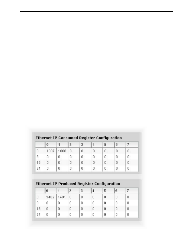
10.8.4 Class 1 (I/O) Data Configuration Arrays
The interface card supports two different types of EtherNet/IP class 1 (I/O) data
transfer. One type is included with the implementation of the AC/DC drive
profile, and requires no user configuration. The other type, however, is entirely
user-configurable, and is utilized when the client opens a connection to the
interface using assembly instances 100 and 150.
The user-configurable data arrays consist of two separate elements (refer to
Figure 37.) The consumed register configuration defines the structure of the
command data sent from the EtherNet/IP controller (for example, a
ControlLogix PLC) to the drive, and the produced register configuration defines
the structure of the status data sent from the drive back to the controller.
These arrays allow the creation of custom-built I/O data. Up to 32 command
registers can be sent to the drive, and up to 32 status registers can be sent
back to the controller. Each box in an array is capable of containing a register
number. Because all drive registers are 16-bit data elements, each box
therefore represents two bytes of consumed or produced data.
Figure 37: EtherNet/IP Class 1 (I/O) Data Configuration
Each of the register array locations are numbered 0-31, and traverse from left
to right across each row, and then increment to the left-most position on the
next row. Clicking on a box in an array allows the user to enter a register
number that will be referenced at that location when data is either consumed
from the controller or produced to the network. A value of 0 indicates that no
register is referenced at that location, which will cause the corresponding
consumed data to be ignored and produced data to be a default value of 0.
As an example, looking at the default configuration shown in Figure 37, we can
see that each array contains two defined registers. Therefore, up to 4
“meaningful” bytes of data can be both received and sent (the qualifier
“meaningful” is used here because the connection sizes configured in the
43
ICC
controller may request larger consumed and/or produced data sizes, but all
unreferenced consumed data will be ignored, and all unreferenced produced
data will contain dummy “0” values). The first word (two bytes) of consumed
data will be written to register 1007 (command 1) and the second word will be
written to register 1008 (frequency command). Similarly, the first word of
produced data will contain the value of register 1402 (status 1) and the second
word will contain the value of register 1401 (output frequency).
10.8.5 Submitting Changes
Whenever any of the EtherNet/IP configuration elements (Device Name or I/O
array configurations) have been changed, the “submit” button located in the
lower right-hand portion of the web page must be clicked in order to write these
settings to the interface card’s filesystem.
Note that because these configuration elements are read from the filesystem
only when the interface card boots up, the act of submitting configuration
changes will also reset the interface card. Please allow 30 seconds for the
interface card to reboot, at which time it will then be operating with the recently-
submitted configuration. Refer to Figure 38.
Figure 38: Submit Configuration Changes
44
ICC
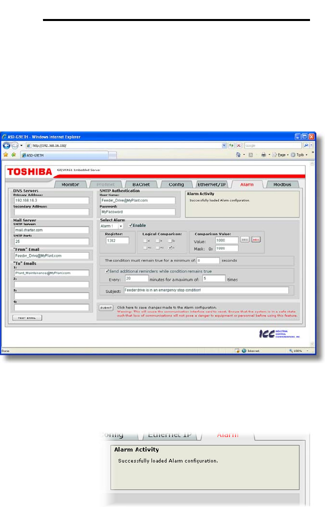
10.9 Alarm Tab
The Alarm tab provides a configurable mechanism by which the interface card
can autonomously monitor any available drive register and send emails to up to
four recipients when a certain condition is detected. The alarm conditions have
both value and time constraints, and can be configured to retrigger at a fixed
interval as long as the alarm condition continues to be satisfied. Twenty
individually-configurable alarms are available. Refer to Figure 39.
Figure 39: Alarm Tab
10.9.1 Information Window
Figure 40 shows the
Information Window,
which is located in the
upper-right hand
corner of the Alarm
tab. This window
displays various
informational
messages regarding
the status of the
Alarm configuration parameters (loading or submitting) and test emails.
Figure 40: Alarm Tab Information Window
45
ICC
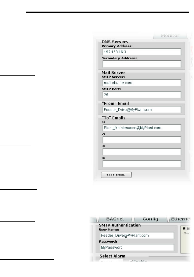
10.9.2 Email Configuration
In order for an alarm trigger to
successfully send a notification
email, some network settings
must first be configured properly
(refer to Figure 41 and Figure 42.)
DNS Servers: Enter the dotted-
decimal IP addresses of the
primary and secondary DNS
servers which will be used to
resolve the configured SMTP
server name. Only the primary
DNS server is required, but if a
secondary DNS server is entered,
then it will be used if the primary
server is inaccessible.
Mail Server: Enter the SMTP
server address as a name or as a
dotted-decimal IP address, and
the SMTP port (default=25) that
the SMTP server listens for
incoming emails on.
“From” Email: Enter the email
address that will appear as the
sender’s email address in the
email headers.
“To” Emails: Up to four
recipients can be designated to
receive alarm emails. Blank
entries will not be processed by
the interface.
“Test Email” Button: When the
“Test Email” button is pressed,
the interface card will use the
information currently entered in
the above-mentioned fields to send a test email. Note that you do not have to
first “submit” the settings to the interface card’s filesystem (refer to section
10.9.4) in order to test them: fields can be changed and retested on-the-fly
without affecting the operation of the interface card’s control protocols. When
the correct settings have been confirmed with a successfully-sent test email,
“submit” the changes at that time to commit them to the interface card’s
filesystem: any changes made prior to submitting as described in section 10.9.4
are temporary only and will be lost if a different configuration tab is selected or if
the web browser is closed.
Figure 41: Email Configuration
Figure 42: SMTP AUTH Configuration
46
ICC
SMTP Authentication: Some email servers require that clients wishing to send
emails first authenticate themselves. If the email server in use requires
authentication, then enter the user name and password as indicated in Figure
42. If the email server in use does not require authentication, then these
entries can be disregarded.
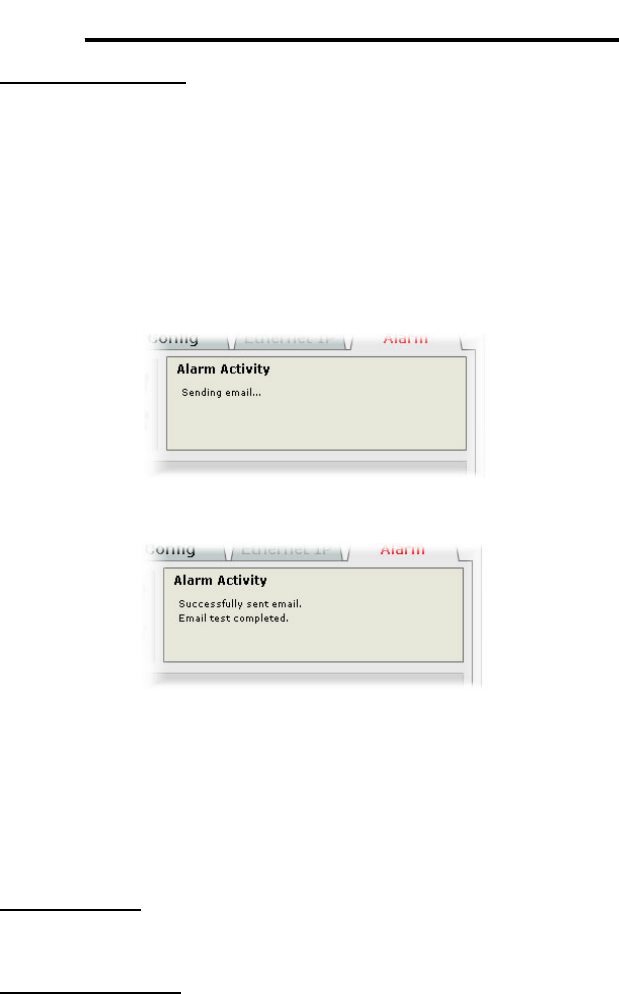
When a test email transmission is initiated, completes successfully, or fails due
to an error, the information window (refer to section 10.9.1) will display
appropriate messages such as those shown in Figure 43 and Figure 44.
Although the test email is sent immediately, note that due to internet and/or
email server delays, it may take several minutes to receive test emails.
Figure 43: Information Window at Test Email Initiation
Figure 44: Information Window at Test Email Successful Completion
10.9.3 Alarm Configuration
The interface supports twenty independently-configurable alarms. As shown in
Figure 45, each alarm has a variety of configuration elements, which will be
explained further below.
Alarm Selection: This drop-down box allows the selection of one of the twenty
available alarms. When an alarm is selected, that alarm’s current configuration
parameters will be populated in the alarm configuration box.
“Enable” Check Box: If checked, this alarm is active and will be evaluated
every second. If unchecked, this alarm is inactive and will therefore not be
evaluated.

47
ICC
Register: Enter the drive register number that this alarm will continuously
monitor. For example, the alarm displayed in Figure 45 is configured to monitor
register 1302, which is “inverter status 1”.
Figure 45: Alarm Configuration Box
Logical Comparison: Choose a comparison operator which will be used to
compare the current value of the indicated “Register” with the reference
“Comparison Value”. Available selections are “less than” (<), “less than or
equal to” (<=), “greater than” (>), “greater than or equal to” (>=), “not equal to”
(!=), and “equal to” (=).
Comparison Value: The reference comparison value is comprised of two
subcomponents: a “Mask” field and a “Value” field. Each time the alarm is
evaluated, the current value of the indicated “Register” is first bit-wise “AND”ed
with the “Mask” field. The resulting derived value is then compared with the
“Value” field by way of the “Logical Comparison” operator. While the “Mask”
field is always a hexadecimal number, the display and entry radix of the “Value”
field can be changed between decimal and hexadecimal with the associated
“DEC” and “HEX” buttons.
Registers that correspond to “analog” process variables (e.g. frequencies,
voltages, etc.) should typically have their “Mask” fields set to 0xFFFF, which
causes all data bits to be retained for the “Value” field comparison. For
registers that correspond to “enumerated” process variables (e.g. status words
where each bit of the register indicates a different item), however, the “Mask”
can be chosen to single out one or more specific data bits of the register. For
example, the “Mask” value of 0x1000 displayed in Figure 45 isolates bit #12 of
“inverter status 1”, which indicates whether or not the drive is in an emergency
stop condition. The “Value” field is also set to a hexadecimal value of 0x1000,
so the alarm condition will be evaluated as “true” when the emergency stop bit
equals 1.
The Condition Must Remain True For A Minimum Of: Alarm analysis
processing is performed by the interface card once per second. Enter the
number of seconds that the condition must be continuously evaluated as “true”

48
ICC
for the alarm to be triggered. A time of 0 seconds means that just a single
evaluation of “true” will immediately trigger the alarm.
Send Additional Reminders While The Condition Remains True: If this
check box is unchecked, then only one email transmission event will occur
when an alarm condition is triggered: further email transmissions will not be
attempted for this alarm unless the alarm condition is first evaluated as “false”
(which resets the alarm), and then once again is triggered by a subsequent
event.
If this check box is checked, then as long as the alarm condition continues to
be evaluated as “true”, subsequent email transmissions will be automatically
retriggered every indicated number of minutes for a maximum of the indicated
number of times. If at any time during the subsequent transmissions the alarm
condition is evaluated as “false”, then the alarm will be reset and email
transmissions for this alarm will stop (until the next time the alarm is triggered,
of course).
Subject: Enter a string of up to 128 characters in length which will appear in
the “subject” line of the alarm email. The body of the alarm email is empty.
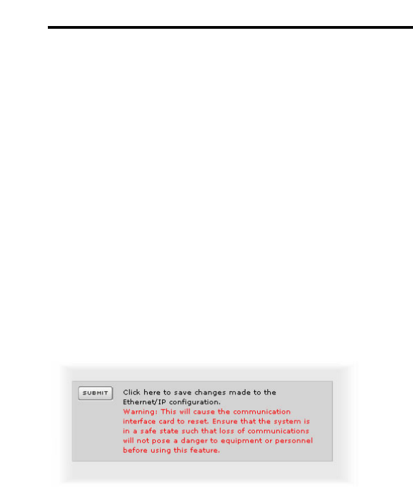
10.9.4 Submitting Changes
Whenever any of the Alarm configuration elements (alarm settings or email
configuration parameters) have been changed, the “submit” button located in
the lower right-hand portion of the web page must be clicked in order to write
these settings to the interface card’s filesystem.
Note that because these configuration elements are read from the filesystem
only when the interface card boots up, the act of submitting configuration
changes will also reset the interface card. Please allow 30 seconds for the
interface card to reboot, at which time it will then be operating with the recently-
submitted configuration. Refer to Figure 46.
Figure 46: Submit Configuration Changes
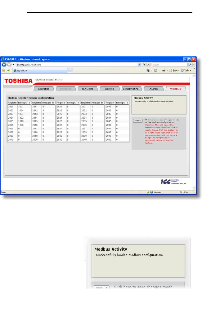
49
ICC
10.10 Modbus Tab
The Modbus tab provides access to configuration items related to
communication on a Modbus TCP network. Refer to Figure 47.
Figure 47: Modbus Tab
10.10.1 Information Window
Figure 48 shows the
Information Window, which is
located in the upper-right hand
corner of the Modbus tab. This
window displays various
informational messages
regarding the status of the
Modbus configuration
parameters (loading or
submitting).
10.10.2 Register Remap Configuration
At times, it may be convenient to access inverter registers in bulk Modbus
transactions. This may be especially true in situations where it is desired to
access certain registers that are natively non-contiguous. For example, if it
Figure 48: Modbus Tab Information
Window
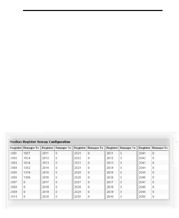
50
ICC
were desired to read the inverter’s status 1 word (register 1302), torque
(register 1319) and output voltage (register 1306), this could be accomplished
in two different ways:
1. Implement three separate Modbus read transactions, each one
reading one register only, or
2. Implement one single Modbus read transaction, starting at register
1302 for a quantity of 18 registers. Then, pick out the registers of
interest and ignore the rest of the response data.
While both of these methods will certainly work, neither one of them is
optimized for the task at hand, which is to access three specific register values.
A fully optimized solution can be realized, however, by making use of the
interface card’s Modbus register remapping capabilities. This mechanism
operates by allocating a block of 50 user-configurable registers (2001..2050)
that remap to other inverter registers. In this way, non-contiguous inverter
registers can be grouped together in any order and accessed efficiently via the
Modbus TCP “read multiple registers” and “write multiple registers” function
codes. The net effect is one of being able to transfer larger blocks of registers
using fewer Modbus transactions, which results in improved network utilization
and simpler data manipulation code on the Modbus master device.
Figure 49: Modbus TCP Register Remap Configuration
Figure 49 shows the register remap configuration array. Clicking on an entry
field in the “Remaps To” column allows the user to enter an inverter register
number that will then be accessible at the register indicated in the adjacent
“Register” column. An assignment of 0 in the “Remaps To” column indicates
that no inverter register is remapped at that location, which results in written
values being ignored and read values returned as a default value of 0. Note
that remapped inverter registers are still accessible at their original locations:
remapping simply provides an additional means of accessing the original
register’s value.
As an example, the configuration shown in Figure 49 reveals that a total of six
inverter registers have been remapped: register 1007 (command 1 word) has
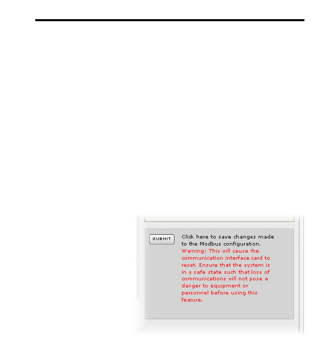
51
ICC
been remapped to register 2001, register 1024 (command 2 word) has been
remapped to register 2002, register 1034 (torque command) has been
remapped to register 2003, register 1302 (inverter status 1) has been
remapped to register 2004, register 1319 (torque) has been remapped to
register 2005, and register 1306 (output voltage) has been remapped to
register 2006. With this configuration, it is now possible to efficiently interact
with these six non-contiguous inverter registers via just two Modbus “read/write
multiple registers” transactions. Writing to the command 1 word, command 2
word and torque command can be accomplished with a single “write multiple
registers” transaction by writing a quantity of three registers starting at register
2001. Similarly, reading the inverter status 1 word, torque and output voltage
(in that order) can be accomplished with a single “read multiple registers”
transaction by reading a quantity of three registers starting at register 2004.
10.10.3 Submitting Changes
Whenever the Modbus
configuration has been
changed, the “submit” button
located on the right-hand
portion of the web page must
be clicked in order to write
these settings to the interface
card’s filesystem. Refer to
Figure 50.
Note that because these
configuration elements are read
from the filesystem only when
the interface card boots up, the
act of submitting configuration
changes will also reset the interface card. Please allow 30 seconds for the
interface card to reboot, at which time it will then be operating with the recently-
submitted configuration.
Figure 50: Submit Configuration Changes

52
ICC
11. Interacting With the Filesystem
The interface card’s on-board filesystem is used to store files for use by the
application firmware. Currently, the application firmware’s main use of the
filesystem is to store XML-encoded configuration files that dictate the
characteristics of the various protocols. Each protocol that requires
configuration will have its own XML file stored on the filesystem. For easy
identification, the filename will begin with the corresponding protocol which it
configures. For example, a BACnet configuration file’s filename will begin with
“bacnet”, and a Profinet I/O file will begin with “pnio”.
Whenever the configuration for a specific protocol is completed, it is suggested
that a backup copy of the configuration file be downloaded from the unit to a
PC. One reason for this is in case it becomes necessary to restore a previous
configuration at a later time. Another reason is that it may be desirable to load
multiple units with the same configuration, as a downloaded configuration file
can be uploaded again to any compatible unit, allowing the user to easily clone
multiple units with the same configuration.
Each time the interface card boots up, it will interrogate the filesystem for the
configuration files required by the protocols currently operating in the unit. If it
does not find a required file, it will create one and initialize it with factory-default
values. Therefore, if it is ever desired to reset a protocol’s configuration to
factory-default values, this can be easily accomplished by simply deleting the
appropriate configuration file from the filesystem and rebooting the unit.
Note that the application firmware uses specific filenames for the configuration
files. This means that if a file with a different filename is loaded onto the unit, it
will be stored correctly, but will not be used by the application firmware.
Similarly, if an existing configuration file’s filename is changed, then the unit will
again create a default configuration file at next boot-up, which will be stored in
the filesystem alongside the file with the changed name.
Configuration files are only read by the protocol drivers at unit boot-up.
Therefore, if a new configuration file is loaded onto a unit’s filesystem, that unit
must be rebooted for the configuration file’s settings to take effect. Rebooting a
unit can be performed by:
• power-cycling the drive in which the card is installed,
• setting drive parameter F899 (register 900) to a value of “1” either via the
keypad, a communication protocol or the web server interface, or
• selecting the “Reboot Device” button in the Finder utility.
Interacting with the filesystem is performed by use of the File Transfer Protocol
(FTP). Using FTP allows the user to interact with the files on the interface
card’s filesystem in the same manner as though they were traditional files
stored on a local or remote PC. While there are many different FTP
applications available, the following sections will provide general examples of
using some of the most commonly-available ones.
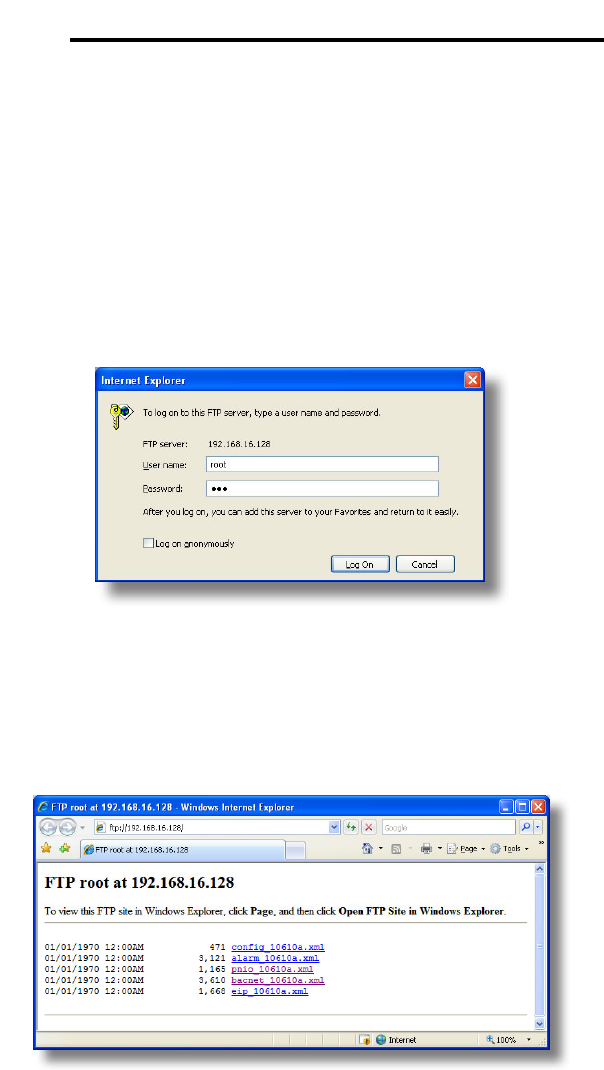
53
ICC
11.1 Initiating FTP via the Finder Utility
After discovering all interface cards on the current subnet as described in
section 8, select the target interface card and then click on the “Open FTP
Interface” button. This will open the computer’s default FTP application, which
could be Windows Explorer, a web browser, or a 3rd-party FTP program
(whatever the computer/operating system is configured for by default). This
example will assume that a web browser (Microsoft Internet Explorer) is
configured as the default FTP application.
An authentication dialog will appear (refer to Figure 51.) Enter the currently-
configured user name and case-sensitive password (defaults are “root” and
“icc”, respectively), then click “Log On.”
Figure 51: FTP Authentication
The web browser will then display the filesystem’s contents (refer to Figure 52.)
FTP access via a web browser allows viewing and downloading files to a
computer, but does not allow advanced file manipulation such as cut, paste,
drag-and-drop, etc. For advanced file manipulation abilities, use of a different
FTP application is required.
Figure 52: FTP Navigation with Internet Explorer
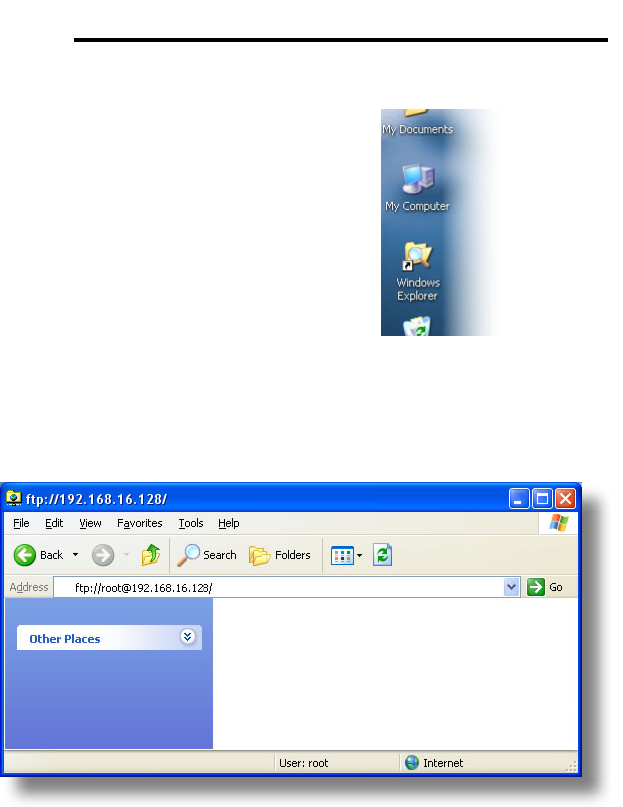
54
ICC
11.2 Using FTP with Windows Explorer
To use FTP with Microsoft
Windows Explorer, first open
either “Windows Explorer” or
“My Computer”. Refer to Figure
53. Please note that the
indicated procedure, prompts
and capabilities outlined here
can vary depending on such
factors as the installed
operating system, firewalls and
service packs.
In the “Address” field, type in
“ftp://root@” and then the IP
address of the target interface card (if the user name has been changed from
its default, then replace “root” in “ftp://root@” with the new user name.) Refer to
Figure 54.
Figure 54: FTP Navigation with Windows Explorer
You will then be presented with an authentication dialog (refer to Figure 55.)
The user name will already be filled-in. Enter the case-sensitive password
(default is “icc”) and click “Log On.”
Figure 53: Accessing Windows Explorer
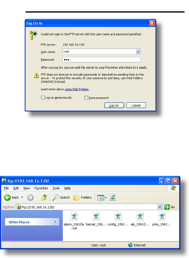
55
ICC
Figure 55: FTP Authentication
Windows Explorer will then display the filesystem’s contents (refer to Figure
56.) You can now perform normal file manipulation actions on the available
files (cut, copy, paste, open, rename, drag-and-drop transfers etc.) in the same
manner as though you were manipulating any traditional file stored on your
computer’s hard drive.
Figure 56: File Access with Windows Explorer
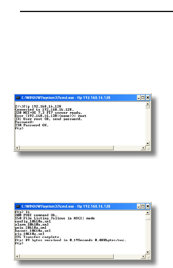
56
ICC
11.3 Using FTP with a Windows Command Prompt
To use FTP with a Windows command (DOS) prompt, first open a command
prompt by either selecting Start…All Programs…Accessories…Command
Prompt, or by selecting Start…Run and typing “cmd” in the “Run” dialog.
Once the command prompt opens, type “ftp” and the IP address of the target
interface card. The FTP client will connect to the unit and then prompt for the
username and case-sensitive password (defaults are “root” and “icc”,
respectively). Upon successful entry of the authentication information, you will
be presented with an “ftp>” prompt. Refer to Figure 57.
Figure 57: FTP Initiation and Authentication
At this point, you can use standard Unix-style file and directory manipulation
commands to perform such actions as listing files (Figure 58), copying files to
your computer (Figure 59), and copying files to the unit (Figure 60).
Figure 58: Listing Files with "ls" Command
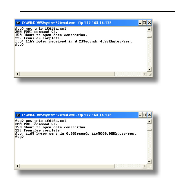
57
ICC
Figure 59: Copying a File from the Unit With "get" Command
Figure 60: Copying a File to the Unit With "put" Command
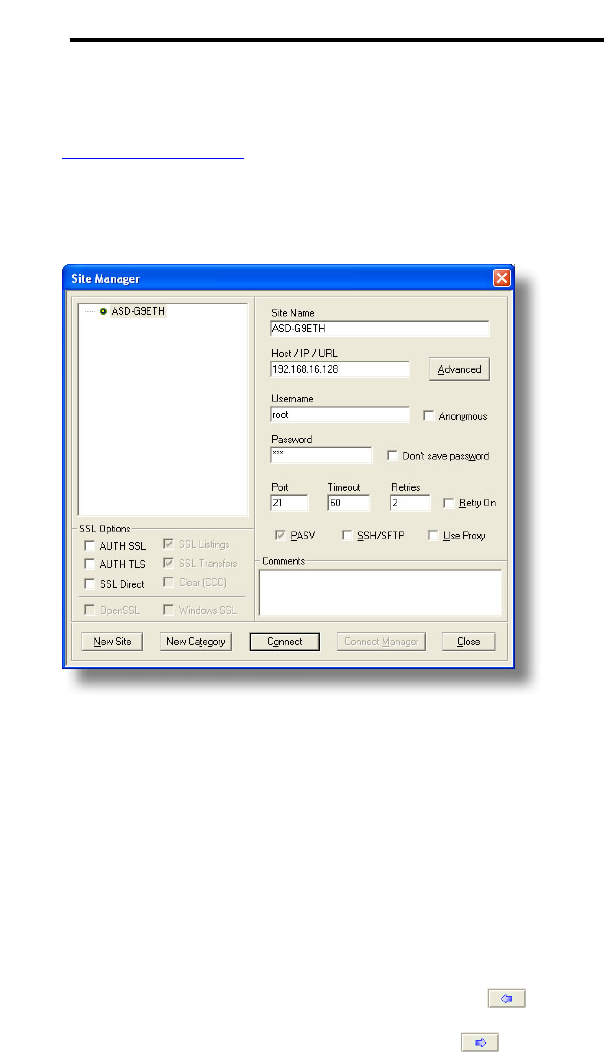
58
ICC
11.4 Using FTP with Core FTP LE
Core FTP LE (Lite) is a 3rd-party FTP application that can be downloaded for
free from http://www.coreftp.com. Core FTP is just one example of the various
commercial and freeware FTP client applications available on the internet.
After installing Core FTP LE, run the program. If the “Site Manager” window
(Figure 61) does not automatically open, open it by choosing “File…connect”.
Figure 61: Core FTP Site Manager
Click on the “New Site” button, then enter a Site Name, IP Address, user name
(default is “root”) and case-sensitive password (default is “icc”). The “Port”,
“Timeout”, and “Retries” fields should already contain the default values. Click
the “Connect” button when done.
Core FTP LE will then try to connect and authenticate to the FTP server, and if
successful, will populate the right-hand side of the main page with the unit’s
filesystem contents. Refer to Figure 62.
Files can be easily downloaded from the unit by choosing the appropriate
destination folder on your computer in the left-hand side of the main page,
choosing the file to download, and then clicking the “download” button in
the right-hand (source) side. Similarly, files can be easily uploaded to the unit
by choosing the file to upload and then clicking the “upload” button in the
left-hand (source) side of the main page.
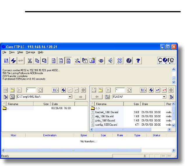
59
ICC
Like most 3rd-party FTP client applications, Core FTP LE has a wide array of
configuration and file management capabilities, which are beyond the scope of
this manual. Refer to the program’s Help file for more detailed instructions.
Figure 62: Core FTP in "Connected" State

60
ICC
12. Loading New Application Firmware
The interface card’s embedded firmware resides in flash memory that can be
updated in the field. Firmware updates may be released for a variety of
reasons, such as custom firmware implementations, firmware improvements
and added functionality as a result of user requests. Additionally, it may be
necessary to load different firmware onto the unit in order to support various
protocols (such as Profinet I/O).
ICC is continually striving to enhance the functionality and flexibility of our
products, and we therefore periodically release new embedded firmware to
achieve these goals and meet customer requests. Flash firmware files and all
related documentation (such as updated user manuals) can be downloaded
from http://www.iccdesigns.com. It is suggested that users check this Internet
site prior to installation, and then periodically afterwards to determine if new
firmware has been released and is available to upgrade their units.
Besides the new firmware file, firmware updates require only a PC with the
same FTP client capabilities as described in section 11. The new firmware is
loaded on the unit via the FTP protocol in the same manner as uploading a
configuration (.XML) file. Some notes on uploading new firmware via FTP are:
• Please be sure to read the firmware release notes and updated user’s
manual for any important notices, behavior precautions or configuration
requirements prior to updating your firmware. For example, upgrading to a
new firmware version may affect user-defined configuration files: prior to
starting an update procedure always back up your configuration file to a PC
for later recovery if necessary.
• Because the FTP application firmware in the unit distinguishes application
firmware files from XML configuration files by virtue of the filename, don’t
change the default name of the firmware file to be uploaded to the unit.
• Although the firmware file is uploaded from your PC to the unit in the same
manner as configuration files are uploaded, the firmware cannot be
downloaded from the unit, because the firmware does not reside in the
unit’s filesystem like configuration files do.
• After the firmware upload process has been completed (typically requiring
30-45 seconds), the unit will reset automatically 5s after the FTP
connection is closed. When the unit boots up again, it will be running the
new application firmware, which can be confirmed by observing the version
displayed in the web server’s information window (refer to section 10.4.1).

61
ICC
13. Protocol-Specific Information
This section will discuss topics that are specific to each of the supported
protocols.
13.1 Modbus/TCP
13.1.1 Overview
The interface card supports Schneider Electric’s Modbus TCP protocol, release
1.0. The interface is conformance class 0 and partial class 1 and class 2
compliant, and allows up to 8 simultaneous Modbus TCP client connections
(sockets). Other notes of interest are:
• Supported Modbus slave functions are indicated in Table 2.
Table 2: Supported Modbus TCP Functions
Function
Code Function Modbus TCP Class
1 Read coils 1
2 Read input status 1
3 Read multiple registers 0
4 Read input registers 1
5 Write coil 1
6 Write single register 1
15 Force multiple coils 2
16 Write multiple registers 0
• Drive registers can be addressed as either holding registers (4X
references) or input registers (3X references). For example, accessing the
output frequency involves accessing holding register 41301 or input
register 31301 (i.e. offset 1301).
• Specific bits within drive registers can be accessed as either coils (0X
references) or discrete inputs (1X references).
• Because the transaction is handled locally within the interface card, write
data checking is not available. For example, if a write is performed to a
register with a data value that is out-of-range of the corresponding
parameter object, no Modbus exception will be immediately returned.
• The “unit identifier” (UI) field of the request packets is ignored.
• The socket timeout time is determined by the “timeout” setting on the web
server’s “Config” tab (refer to section 10.7.4). This means that if a

62
ICC
particular open socket experiences no activity for more than the timeout
time setting, then the interface assumes that the client or network has
experienced some sort of unexpected problem, and will close that socket.
• Because the socket timeout determination is performed on a per-socket
basis, note that a certain degree of caution must be exercised when using
the network timeout feature to avoid “nuisance” timeouts from occurring.
Specifically, do not perform inadvisable behavior such as sending a
request from the master device to the interface, and then closing the
socket prior to successfully receiving the unit’s response. The reason for
this is because the interface will then experience an error when attempting
to respond via the now-closed socket, which will immediately trigger the
timeout action. Always be sure to manage socket life cycles “gracefully”,
and do not abandon outstanding requests.
• If a socket timeout occurs (regardless of whether it was due to a
communication lapse or abnormal socket error), the driver will trigger a
timeout event as described in section 10.7.4.
13.1.2 Coil & Discrete Input Mappings
The Modbus TCP driver provides read/write support for coils (0X references)
and read-only support for discrete inputs (1X references). These will
collectively be referred to from here on out as simply “discretes”. Accessing
discretes does not reference any new physical data: discretes are simply
indexes into various bits of existing registers. What this means is that when a
discrete is accessed, that discrete is resolved by the interface into a specific
register, and a specific bit within that register. The pattern of discrete-to-
register/bit relationships can be described as follows:
Discrete 1...16 map to register #1, bit0...bit15 (bit0=LSB, bit15=MSB)
Discrete 17...32 map to register #2, bit0...bit15, and so on.
Arithmetically, the discrete-to-register/bit relationship can be described as
follows: For any given discrete, the register in which that discrete resides can
be determined by:
⎥
⎦
⎥
⎢
⎣
⎢+
=16
15discrete
register Equation 1
Where the bracket symbols “⎣ ⎦” indicate the “floor” function, which means that
any fractional result (or “remainder”) is to be discarded, with only the integer
value being retained.
Also, for any given discrete, the targeted bit in the register in which that discrete
resides can be determined by:
161discretebit %)(
−
= Equation 2

63
ICC
Where “discrete” ∈[1…65535], “bit” ∈[0…15], and “%” is the modulus operator,
which means that any fractional result (or “remainder”) is to be retained, with
the integer value being discarded (i.e. it is the opposite of the “floor” function).
For clarity, let’s use Equation 1 and Equation 2 in a calculation example. Say,
for instance, that we are going to read coil #34. Using Equation 1, we can
determine that coil #34 resides in register #3, as ⎣3.0625⎦ = ⎣3 r1⎦ = 3. Then,
using Equation 2, we can determine that the bit within register #3 that coil #34
targets is (34-1)%16 = 1, as 33%16 = mod(2 r1) = 1. Therefore, reading coil
#34 will return the value of register #3, bit #1.

64
ICC
13.2 EtherNet/IP
13.2.1 Overview
The EtherNet/IP protocol is an application-level protocol implemented on top of
the Ethernet TCP/IP and UDP/IP layers. It shares its object model with
ControlNet and DeviceNet through the common Control and Information
Protocol (CIP). This protocol allows the transfer of data and I/O over Ethernet.
EtherNet/IP incorporates both the TCP and UDP layers of Ethernet in the
transmission of data. Because TCP/IP is a point-to-point topology, EtherNet/IP
uses this layer only for explicit messaging; i.e. those messages in which the
data field carries both protocol information and instructions for service
performance. With explicit messaging, nodes must interpret each message,
execute the requested task and generate responses. These types of messages
can be used to transmit configuration, control and monitor data.
The UDP/IP protocol layer, which has the ability to multi-cast, is used for
implicit (I/O) messaging. With I/O messaging, the data field contains only real-
time I/O data; no protocol information is sent because the meaning of the data
is pre-defined at the time the connection is established, which in turn minimizes
the processing time of the node during run-time. I/O messages are short and
have low overhead, which allows for the time-critical performance needed by
controllers.
The interface card supports both explicit and I/O messaging. Further, two
different types of I/O messaging are supported. One type (invoked when the
client opens a connection to the interface using assembly instances 20 & 70 or
21 & 71) is included with the implementation of the AC/DC drive profile, and
requires no user configuration. The other type, however, is entirely user-
configurable, and is invoked when the client opens a connection to the interface
using assembly instances 100 and 150.
The following sections demonstrate specific examples of how to use
EtherNet/IP to transfer data between the drive and Allen-Bradley Logix-brand
PLCs.
Some other notes of interest are:
• The interface card supports the EtherNet/IP protocol (release 1.0),
administered by the Open DeviceNet Vendor Association (ODVA).
• This product has been self-tested by ICC, Inc. and found to comply with
ODVA EtherNet/IP Conformance Test Software Version A-5.
• I/O connection sizes for assembly instances 100 and 150 are adjustable
between 0 and 64 bytes (32 registers max @ 2 bytes per register = 64
bytes). Because registers are 16-bit elements, however, connection sizes
cannot be odd (i.e. 1, 3, 5 etc.)
• The interface card’s product type code is 2 (AC drive.)

65
ICC
• Supports unconnected messages (UCMM), and up to 16 simultaneous
class 1 (I/O) or class 3 (explicit) connections.
• Assembly instances 100 and 150: if a register entry in the consumed data
configuration array is 0, then any consumed data that corresponds to that
location will be ignored. Conversely, if a register entry in the produced
data configuration array is 0, then any produced data that corresponds to
that location will be a default value of 0. Refer to section 10.8.4 for further
information on the data configuration arrays.
• Point-to-point class 1 connected messages will be produced targeting the
IP address of the device that instantiated the connection, port 0x08AE (port
2222).
• If a class 1 connection’s consuming half (O→T) times out, then the
producing half (T→O) will also time-out and will stop producing.
• If a class 1 or class 3 connection timeout occurs, the driver will trigger a
timeout event as described in section 10.7.4.
13.2.2 ODVA AC/DC Drive Profile
The interface card supports the ODVA AC/DC drive profile. No special
Ethernet/IP configuration of the interface card is required when using the
AC/DC drive profile: all that is needed is that the controller must target either
assembly instances 20 & 70 or 21 & 71 in its connection parameters.
The AC/DC drive profile
implementation provides
support for several
required CIP objects,
which are specified in
Table 3. While the
various supported
attributes of all of these
objects are accessible via
explicit messaging, the
main intent of using the AC/DC drive profile is to interact with the predefined
input and output assembly instances via an I/O connection. The structure of
these assembly instances is defined by the Ethernet/IP specification in order to
engender interoperability among different vendor’s products. This section will
focus primarily on the format of the AC/DC drive profile I/O assemblies
supported by the interface card, and the inverter data which their various
constituent elements map to.
Table 3: AC/DC Drive Profile-Related Objects
Class Code Object Name
0x04 Assembly Object
0x28 Motor Data Object
0x29 Control Supervisor Object
0x2A AC Drive Object

66
ICC
Output Instances 20 and 21 Detail
Instance Byte Bit
7 Bit
6 Bit
5 Bit
4 Bit
3 Bit
2 Bit
1 Bit
0
0 Fault
Reset Run
Fwd
1
2 Speed Reference (Low Byte)
20
3 Speed Reference (High Byte)
0 NetRef NetCtrl Fault
Reset Run
Rev Run
Fwd
1
2 Speed Reference (Low Byte)
21
3 Speed Reference (High Byte)
Mapping Detail
Run Fwd: forward rotation command (0=forward rotation off, 1=forward rotation
on). Maps to inverter register 1007, bits 9 and 10. Run Fwd = 1 translates to
inverter register 1007 bit 9 (direction) = 0 and bit 10 (run/stop) = 1. Note that if
both the “Run Fwd” and “Run Rev” bits are on, then inverter register 1007 will
not be changed from its previous value.
Run Rev: reverse rotation command (0=reverse rotation off, 1=reverse rotation
on). Maps to inverter register 1007, bits 9 and 10. Run Rev = 1 translates to
inverter register 1007 bit 9 (direction) = 1 and bit 10 (run/stop) = 1. Note that if
both the “Run Fwd” and “Run Rev” bits are on, then inverter register 1007 will
not be changed from its previous value.
Fault Reset: Inverter reset command (0=no action, 0→1 rising edge=reset).
Maps to inverter register 1007, bit 13 (fault reset).
NetCtrl: Run/stop control source selection (0=local control, 1=network control).
Maps to inverter register 1007, bit 15 (command priority).
NetRef: Speed reference source selection (0=local control, 1=network control).
Maps to inverter register 1007, bit 14 (frequency priority).
Speed Reference: Inverter speed reference in RPM. Maps to inverter register
1008 (frequency command). Because the inverter always requires a frequency
command value in units of Hz, the interface card applies an RPM-to-Hz
conversion equation. The general RPM-to-Hz conversion equation is [RPM x
number of motor poles / 120]. However, for simplicity the interface card always
assumes that a 4-pole motor is in use, thereby reducing the applied conversion
equation to [frequency command value = RPM / 30].

67
ICC
Input Instances 70 and 71 Detail
Instance Byte Bit
7 Bit
6 Bit
5 Bit
4 Bit
3 Bit
2 Bit
1 Bit
0
0 Running
1 Fault
1
2 Speed Actual (Low Byte)
70
3 Speed Actual (High Byte)
0 At
Ref
Ref
From
Net
Ctrl
From
Net Rdy Running
2 (REV) Running
1 (FWD) Warn Fault
1 Drive State
2 Speed Actual (Low Byte)
71
3 Speed Actual (High Byte)
Mapping Detail
Faulted: Inverter fault signal (0=not faulted, 1=faulted). Maps to inverter
register 1302 (status 1 word), bit 0.
Warning: This bit is not used (it is always 0).
Running1 (FWD): Running forward status signal (0=not running forward,
1=running forward). Maps to inverter register 1302 (status 1 word), bits 9 and
10. The Running1 bit will be 1 whenever inverter register 1302 bit 9 (direction)
is 0 and bit 10 (running/stopped) is 1, and will be 0 otherwise.
Running2 (REV): Running reverse status signal (0=not running reverse,
1=running reverse). Maps to inverter register 1302 (status 1 word), bits 9 and
10. The Running2 bit will be 1 whenever inverter register 1302 bit 9 (direction)
is 1 and bit 10 (running/stopped) is 1, and will be 0 otherwise.
Ready: Inverter ready signal (0=not ready, 1=ready). The Ready bit will be 1
whenever the Drive State attribute (see below) is in the Ready, Enabled or
Stopping state.
CtrlFromNet: Inverter command reference status (0=command reference is not
from network, 1=command reference is from network). Maps to inverter
register 1007, bit 15 (command priority). In other words, CtrlFromNet always
reflects the status of the NetCtrl attribute.
RefFromNet: Inverter speed reference status (0=speed reference is not from
network, 1=speed reference is from network). Maps to inverter register 1007,
bit 14 (frequency priority). In other words, RefFromNet always reflects the
status of the NetRef attribute.
AtReference: Up-to-speed signal (0=not up-to-speed, 1=up-to-speed). Maps
to inverter register 1350 (status 3 word), bit 12 (RCH).
Drive State: Indicates the current state of the Control Supervisor Object state
machine. Refer to the ODVA Ethernet/IP specification (object library) for
detailed information on the Control Supervisor Object state machine.
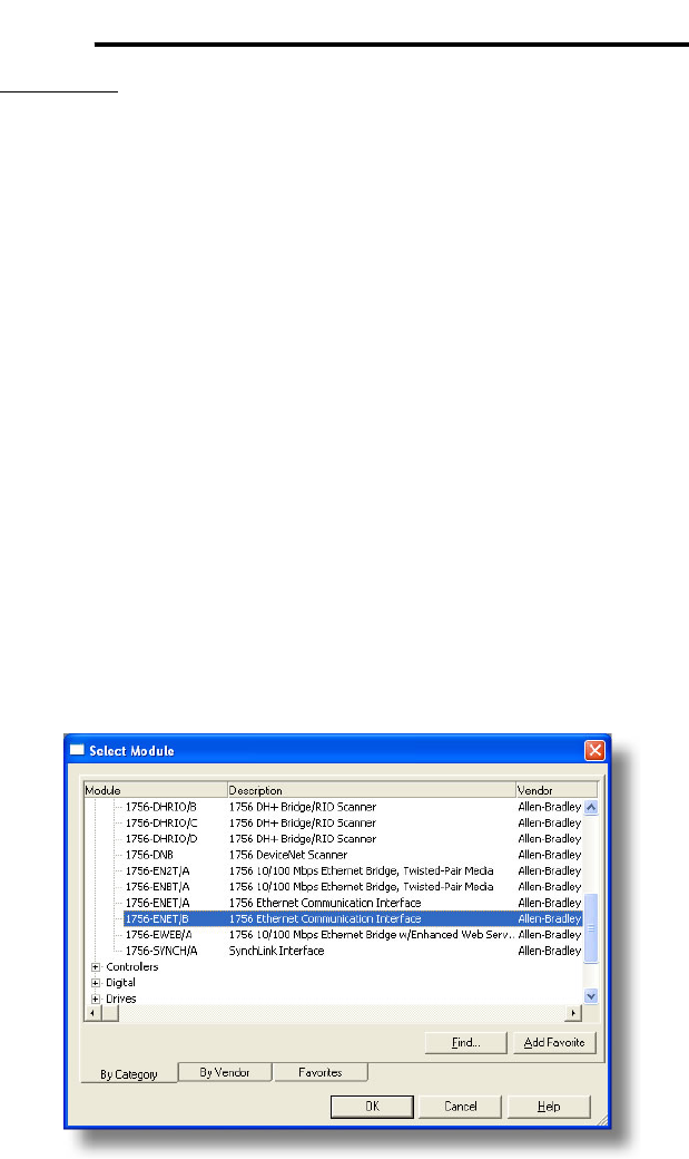
68
ICC
Speed Actual: Inverter operating speed in RPM. Maps to inverter register
1301 (output frequency). Because the inverter always provides its output
frequency in units of Hz, the interface card applies a Hz-to-RPM conversion
equation. The general Hz-to-RPM conversion equation is [output frequency x
120 / number of motor poles]. However, for simplicity the interface card always
assumes that a 4-pole motor is in use, thereby reducing the applied conversion
equation to [RPM = output frequency value x 30].
13.2.3 ControlLogix Examples: Setup
This section will demonstrate how to initially setup a ControlLogix PLC (such as
a 1756-L61) coupled with a 1756-ENBT communications bridge (adjust this
procedure according to your specific equipment). Later sections will provide
specific read/write examples using this configuration with I/O or explicit
messaging.
1) Run RSLogix 5000, and create a new configuration.
2) To add a 1756-ENET/B to your I/O configuration, first switch to offline
mode.
3) Right click on the I/O Configuration node in the controller organizer view
and choose “New Module…”
4) The “Select Module” window will open.
5) Under “Communications”, select “1756-ENET/B”, and click OK. Refer to
Figure 63.
Figure 63: Adding a New Module
6) The “New Module” window will open. Refer to Figure 64.
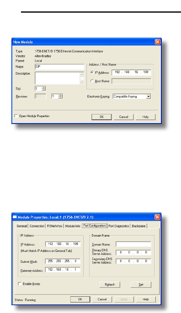
69
ICC
7) Assign the Ethernet module a name (we will use “EIP”) and an IP address,
deselect “Open Module Properties”, and click OK.
Figure 64: Identifying the New Module
8) Download the configuration.
9) Switch to online mode. Right click on the 1756-ENET/B module in the I/O
Configuration and choose “Properties”.
10) Select the Port Configuration tab from the Module Properties dialog box.
11) Confirm that the IP Address, Subnet Mask and Gateway Address fields are
configured correctly. The IP Address must match the IP Address entered
when the new module was first created. Refer to Figure 65.
Figure 65: Confirming the Module's Properties
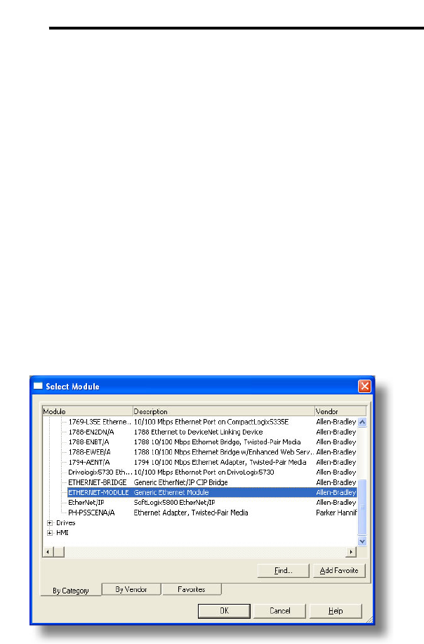
70
ICC
12) Apply the settings using the “Set” button.
13) You should now be able to confirm that the 1756-ENET/B module is
configured properly by (for example) opening the module’s web interface in
a web browser.
13.2.4 ControlLogix Example: I/O Messaging
This section will demonstrate how to setup and use an EtherNet/IP I/O
connection via vendor-specific assembly instances 100 & 150. EtherNet/IP I/O
messaging allows the drive’s registers to be directly mapped into tags in the
ControlLogix PLC. Once an I/O connection is established, it is automatically
synchronized at an interval defined by the Requested Packet Interval (RPI).
1) Switch to offline mode.
2) Right click on the 1756-ENET/B node under the I/O Configuration in the
controller organizer view and choose “New Module…”
3) Choose “Generic Ethernet Module” in the Select Module dialog box and
click “OK”. Refer to Figure 66.
Figure 66: Adding a New Generic Ethernet Module
4) The module properties dialog box will open (refer to Figure 67). Enter a
Name and Description which will allow easy identification of the drive on
the network (the tags created in RSLogix 5000 will be derived from this
Name). Because all drive data is stored as 16-bit registers, change the
“Comm Format” selection to “Data-INT”. Enter the IP address of the
targeted interface card.

71
ICC
In the “Connection Parameters” portion of the dialog box, enter the
following information:
Input: The Input Assembly is the collection of monitor data that is
produced by the interface card and is received as an input to the PLC. Its
structure is defined by the Produced Register Configuration as described in
section 10.8.4. The Input Assembly Instance must be set to 150 when
connecting to the vendor-specific I/O assembly instances (or 70/71 when
using the ODVA AC/DC drive profile), and the size must be set to the
number of 16-bit registers that we wish to receive from the interface card.
For the purposes of this example, we are assuming that the produced
configuration array is defined as shown in Figure 37, with two relevant
registers (1402 and 1401). We therefore set the Input Size to 2.
Output: The Output Assembly is the collection of command &
configuration data that is sent as an output from the PLC and consumed by
the interface card. Its structure is defined by the Consumed Register
Configuration as described in section 10.8.4. The Output Assembly
Instance must be set to 100 when connecting to the vendor-specific I/O
assembly instances (or 20/21 when using the ODVA AC/DC drive profile),
and the size must be set to the number of 16-bit registers that we wish to
send to the interface card. For the purposes of this example, we are
assuming that the consumed configuration array is defined as shown in
Figure 37, with two relevant registers (1007 and 1008). We therefore set
the Output Size to 2.
Configuration: The Configuration Assembly Instance is unused, and its
instance number and size are therefore irrelevant (you can just enter “1”
and “0”, respectively).
When done, click “OK”.
Figure 67: Interface Card Module Properties
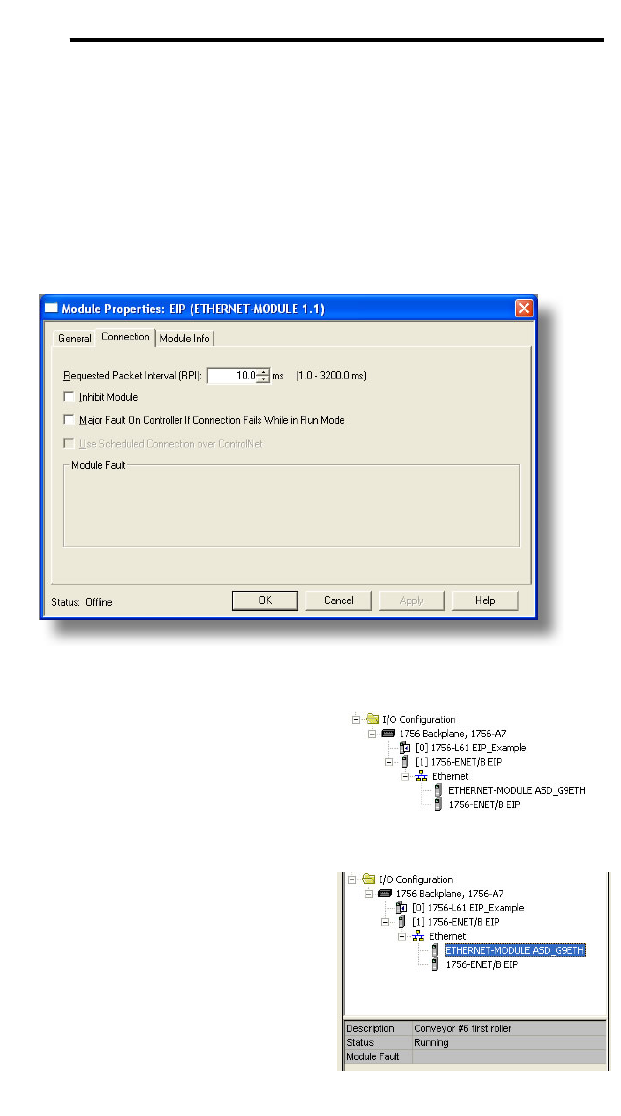
72
ICC
5) You should now see the new module (named “ETHERNET-MODULE
ASD_G9ETH”) in the 1756-ENET/B branch under the I/O Configuration in
the controller organizer view. Right click on this new module, choose
“Properties”, and select the Connection tab. Refer to Figure 68.
Confirm the setting of the Requested Packet Interval (RPI). The RPI
defines the amount of time (in milliseconds) between data exchanges
across an I/O connection. The smallest RPI supported by the interface
card is 10ms.
Click OK when done.
Figure 68: Module Properties Connection Tab
6) After adding the I/O Module to the
configuration, the full I/O
Configuration tree should appear
similar to Figure 69.
7) Switch to online mode and
download the project to the PLC.
Verify that the newly-added drive is
available and operating correctly by
observing any indications shown on
the drive’s icon. When the drive’s
icon is selected, its status and any
available error messages will be
displayed in the area below the
project tree. Refer to Figure 70.
Also confirm that the interface card’s
“Network Status” LED should be
Figure 69: I/O Configuration Tree
Figure 70: Online Module Status
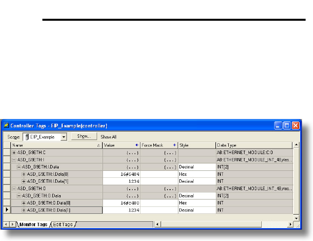
73
ICC
solid green, indicating an “online/connected” state.
8) By double-clicking “Controller Tags” in the project tree, it is possible to view
the newly-added tags. Refer to Figure 71. The ASD_G9ETH:C
configuration tag is unused, the ASD_G9ETH:I tag allows viewing of the
input data, and the ASD_G9ETH:O tag allows modification of the output
data. These tags will be synchronized with the drive at whatever rate was
established for the module’s RPI.
Figure 71: Controller Tags for I/O Access
We can directly interact with these tags in order to control and monitor the
drive. In Figure 71, we can see that the first 16-bit word of output data
(ASD_G9ETH:O.Data[0]) has been set to a hexadecimal value of 0xC400.
Referring back to Figure 37, we can see that the first element of the consumed
register configuration references register 1007, which is the drive’s option board
Command 1 register. A value of 0xC400, therefore, means that the frequency
priority, command priority, and run bits have been turned ON.
Similarly, we can see that the second 16-bit word of output data
(ASD_G9ETH:O.Data[1]) has been set to a decimal value of 1234. Once again
referring back to Figure 37, we can see that the second element of the
consumed register configuration references register 1008, which is the drive’s
option board frequency command register. A value of 1234, therefore, equates
to a frequency command of 12.34Hz.
The input data from the drive shows similar expected results. Values of 0x6404
and 1234 corresponding to registers 1402 (inverter status 1) and 1401 (output
frequency), respectively, are consistent with the drive running at the parameters
commanded by the output tag.
13.2.5 Explicit Messaging Tag Reference
When class 3 (explicit messaging) connections are used, register contents are
read from and written to the interface card via EtherNet/IP by reference to “tag
names”. Tags are read via the EtherNet/IP “data table read” service, and tags

74
ICC
are written via the EtherNet/IP “data table write” service. Different tags exist for
reading vs. writing.
Any given register can be accessed with its own unique tag name, or an array
tag can be used to access a group of registers with one PLC instruction. Tag
names are generated according to the following structure:
[action prefix][_reg_][register number]
Where
[action prefix] is a 2-character field, and is equal to either “rd” for read tags, or
“wr” for write tags. Although commonly followed for naming clarity, this “read
vs. write” naming convention is not strictly enforced by the interface card,
however: it is perfectly acceptable to write to a tag that starts with “rd” and read
from a tag that starts with “wr”.
[_reg_] is just the 5-character sequence “_reg_”.
[register number] is a 1- to 4-character field (“1”, “2”…”1484”, “1485”)
corresponding to the referenced register number.
Examples
Read “acceleration time 1” (register #10) ...................................rd_reg_10
Write “option frequency command” (register #1008) ..................wr_reg_1008
Read “inverter status 1” (register #1402)....................................rd_reg_1402
Additionally, a few special tags exist which provide backward-compatibility with
V1.000 network interface CPU firmware. These are specified in Table 4.
Table 4: Special Tag Reference
Service Tag Name Register Start Same As…
Data table read rd_reg_basic 1 rd_reg_1
Data table read rd_freq_out 1401 rd_reg_1401
Data table read rd_inv_stat1 1402 rd_reg_1402
Data table read rd_torq_out 1419 rd_reg_1419
Data table read rd_inv_stat2 1443 rd_reg_1443
Data table write wr_reg_basic 1 wr_reg_1
Data table write wr_cmd1 1007 wr_reg_1007
Data table write wr_freq_cmd 1008 wr_reg_1008
Data table write wr_cmd2 1024 wr_reg_1024
Data table write wr_torq_cmd 1034 wr_reg_1034
To read data from the interface card, the application PLC program must
reference a “source element” from which to start reading and the “number of
elements” to read. The “source element” will be a tag name constructed
according to the naming convention shown above, or a special tag as shown in
Table 4. The “source element” can be either a base tag (such as
“rd_reg_1301”, which starts at register 1301), or an offset from a base tag (such
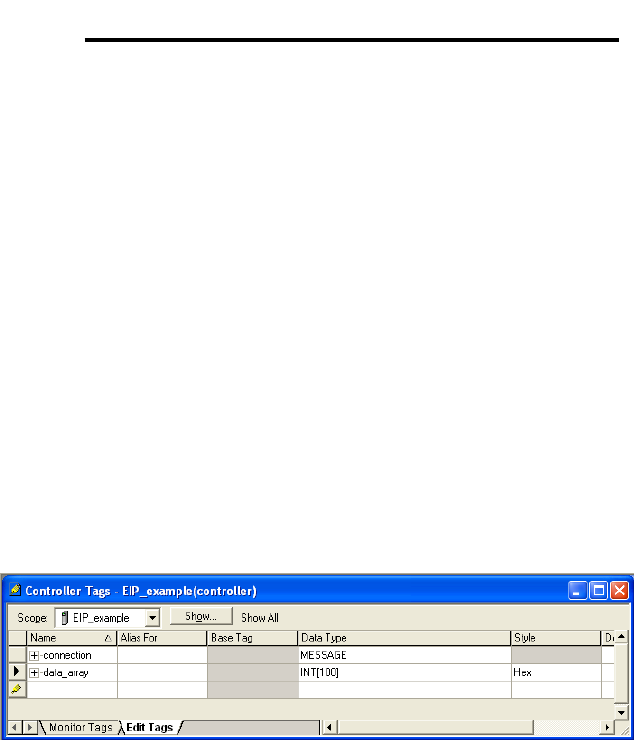
75
ICC
as “rd_reg_1301[4]”, which starts at register 1301+4 = register 1305, the drive’s
input voltage monitor register).
In a similar manner, to write data to the interface card, the application PLC
program must reference a “destination element” to which to start writing and the
“number of elements” to write. Again, the “destination element” will be a tag
name constructed according to the naming convention shown above, or a
special tag as shown in Table 4.
Whether reading or writing, the “number of elements” can be any quantity of
registers from 1 to the maximum allowable length (1485).
13.2.6 ControlLogix Example: Read a Register Block
This example program will show how to continuously read a block of registers
from the drive with a single MSG instruction. Only one read request is
outstanding at any given time.
1) Create new Tags.
a) Double click “Controller Tags” in the controller organizer view.
b) The “Controller Tags” window appears. Refer to Figure 72.
Figure 72: Create New Tags
c) Select the “Edit Tags” tab at the bottom.
d) Create a new tag by entering “connection” in the first blank Name field,
and change its Data Type to “MESSAGE”. This tag will contain
configuration information for the MSG instruction.
e) Select the “Monitor Tags” tab. Expand the “connection” tag by clicking
on the “+” sign next to the tag name. Scroll down to the
connection.UnconnectedTimeout field and change its value from the
default 30000000 (30s in 1uS increments) to 1000000 (1s). This value
determines how long to wait before timing out and retransmitting a
connection request if a connection failure occurs. Refer to Figure 73.
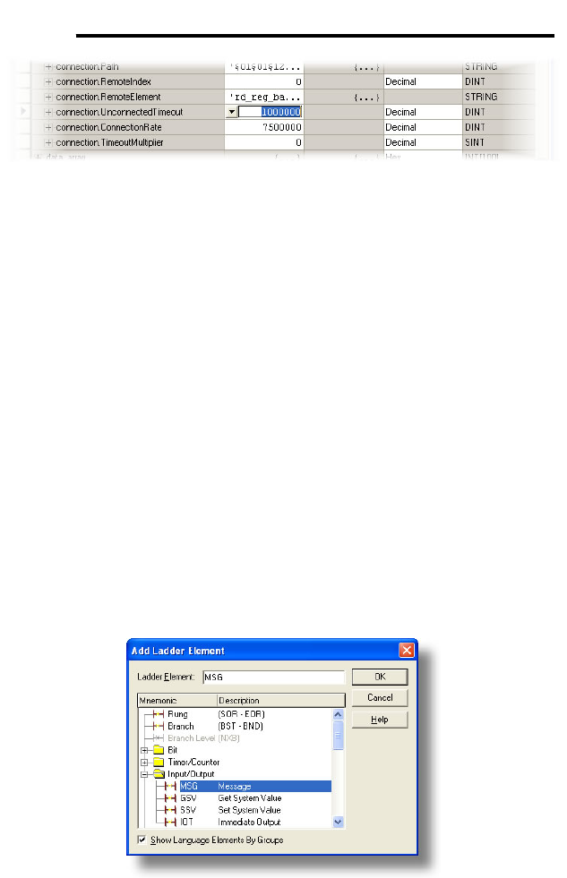
76
ICC
Figure 73: Reduce the UnconnecteTimeout Value
f) Collapse the “connection” tag again by clicking on the “-“ sign next to
the tag name.
g) Select the “Edit Tags” tab again. Create another new tag by entering
“data_array” in the next blank Name field, and change its Data Type
by typing in “INT[100]” in the Data Type field. This tag is an array of
INTs that will be able to hold up to 100 16-bit registers from the drive.
Always make sure that the destination tag size is large enough to hold
all elements to be read.
2) Add a MSG instruction to the main program.
a) Double click “MainRoutine” under Tasks …MainTask …MainProgram
in the controller organizer view.
b) Right click on the first ladder logic rung in the MainRoutine window
and select “Add Ladder Element...”
c) The “Add Ladder Element” window appears.
d) Select the “MSG” instruction in the Input/Output folder. Refer to
Figure 74.
e) Click OK.
Figure 74: Adding a MSG Instruction
3) Add an XIO element to the main program.
a) Right click on the ladder logic rung containing the MSG instruction in
the MainRoutine window and select “Add Ladder Element...” again.
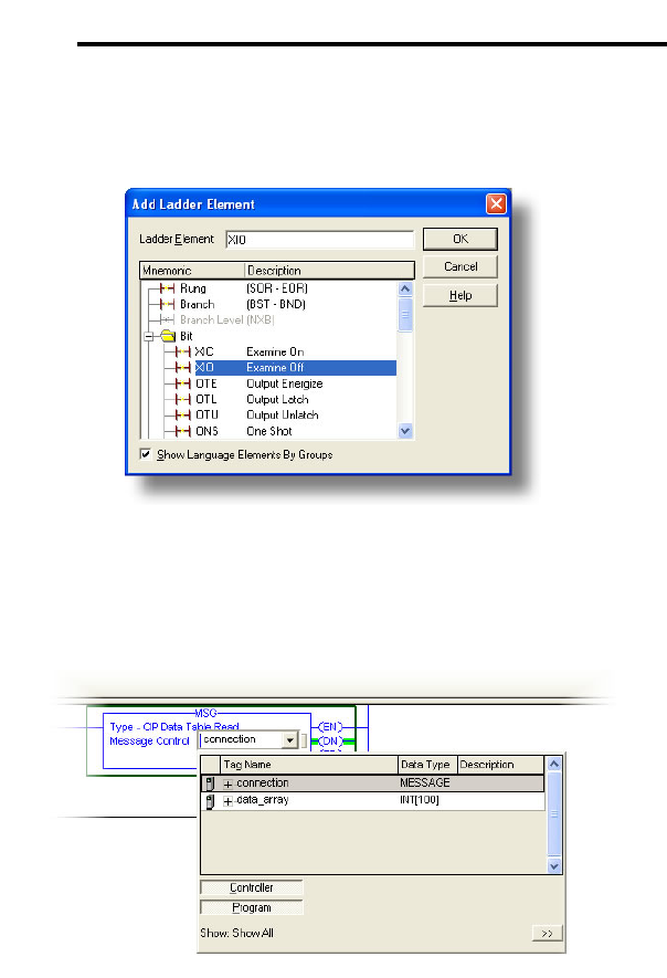
77
ICC
b) The “Add Ladder Element” window appears.
c) Select the “XIO” element in the Bit folder. Refer to Figure 75.
d) Click OK.
Figure 75: Adding an XIO Element
4) Configure the MSG instruction.
a) Edit the “Message Control” field on the MSG instruction to use the
previously-created “connection” tag. Refer to Figure 76.
Figure 76: MSG Instruction Tag Assignment
b) Click the message configuration button (“…”) in the MSG instruction.
The “Message Configuration” window will open. Refer to Figure 77.
c) “Configuration” tab settings:
i) Change the “Message Type” to “CIP Data Table Read”.
ii) In the "Source Element” field, enter the read tag you wish to
access (refer to section 13.2.5.) In this example, we will be
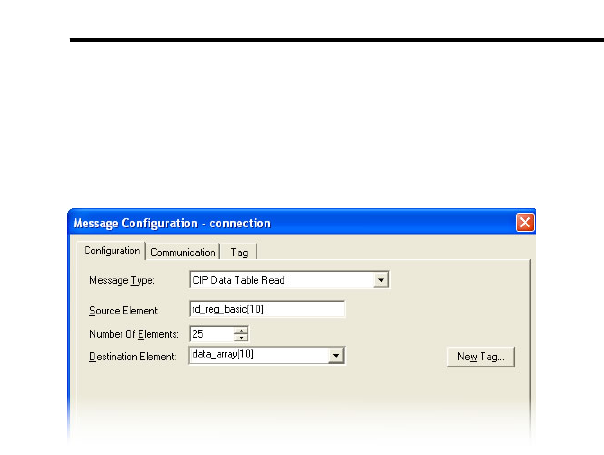
78
ICC
reading a total of 25 registers beginning at rd_reg_basic[10].
Offset 10 in the interface card’s rd_reg_basic root tag (which
starts at register 1) refers to 1+10 = register 11 (deceleration time
1). If we wish, we could also use the tag name which references
deceleration time 1 directly (rd_reg_11) to achieve the same
results.
Figure 77: MSG Instruction Configuration
iii) Enter the Number Of Elements to read. In this example, we will
read 25 registers.
iv) For the Destination Element, either directly type in
“data_array[10]”, or select element #10 in the data_array tag via
the drop-down box (refer to Figure 78). The destination could be
any offset in the data_array tag, as long as the offset plus the
Number Of Elements (25) does not exceed the tag’s defined size
(100).
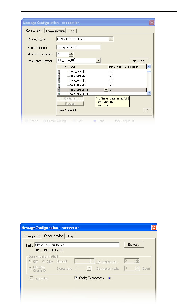
79
ICC
Figure 78: Selecting the Destination Element
d) “Communication” tab settings (refer to Figure 79):
i) Enter the Path to the interface card. A typical path is formatted as
“Local_ENB,2,target_IP_address”, where:
• Local_ENB is the name of the 1756-ENBx module in the local
chassis (we named ours “EIP” in section 13.2.3),
• 2 is the Ethernet port of the 1756-ENBx module in the local
chassis, and
• target_IP_address is the IP address of the target node.
In our example, this path would be entered as
“EIP,2,192.168.16.128”.
Figure 79: Setting the Communication Path
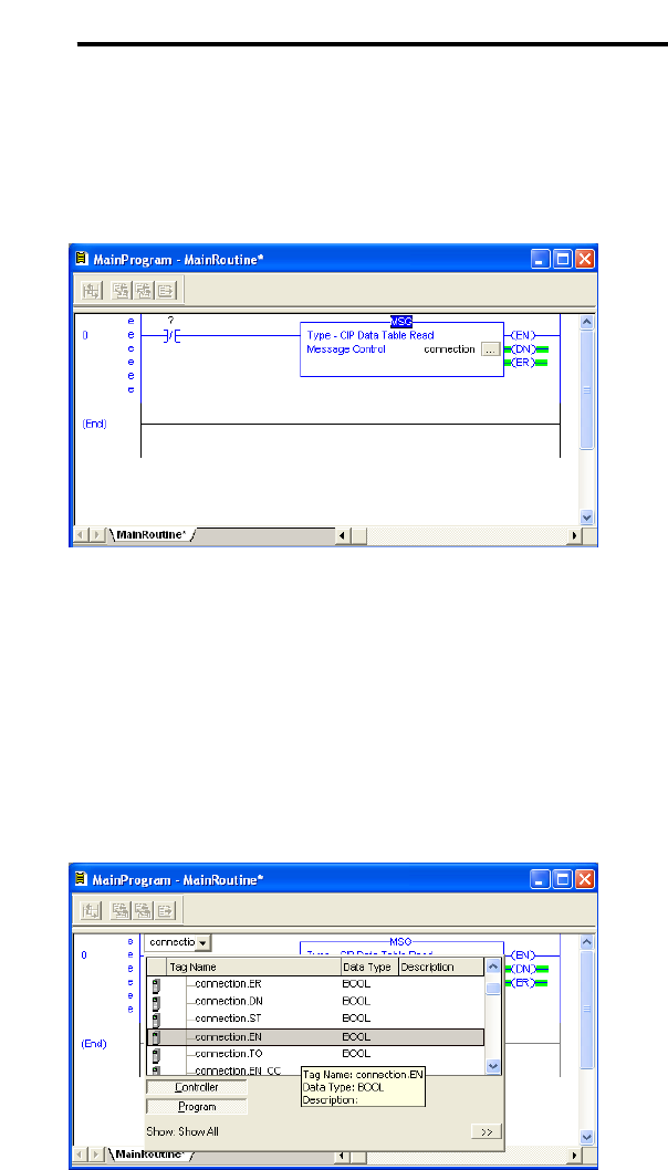
80
ICC
ii) If “Cache Connections” is enabled (checked), the connection
remains open after transmission. If disabled (unchecked), the
connection is opened before and closed after every transmission.
For efficiency, it is recommended to enable “Cache Connections”.
e) Click “OK” to close the MSG Configuration dialog. At this stage,
MainRoutine should look like Figure 80.
Figure 80: MainRoutine
5) Assign a tag to the XIO element.
a) Double-click on the XIO element located to the left of the MSG block.
In the drop-down box, double-click on the “connection.EN” field. Refer
to Figure 81. This configuration causes the MSG instruction to
automatically retrigger itself when it completes. While this is
acceptable for the purposes of this example, it can produce high
network utilization. In actual practice, it may be desirable to
incorporate additional logic elements to allow triggering the MSG
instruction at a specific rate or under specific conditions.
Figure 81: Configure XIO Element
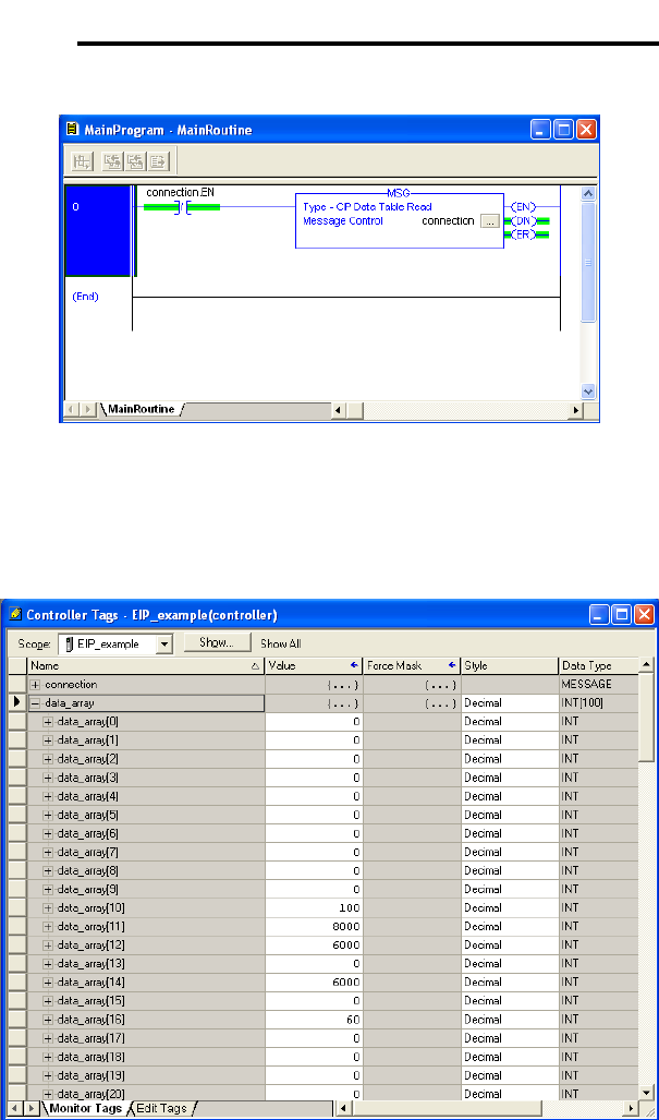
81
ICC
6) The program is now complete. Refer to Figure 82.
Figure 82: Complete Program
7) Save, download and run the program.
a) To view the values of the registers being read from the interface card,
double-click “Controller Tags” in the controller organizer view.
Figure 83: Viewing the Register Values
b) Select the “Monitor Tags” tab.
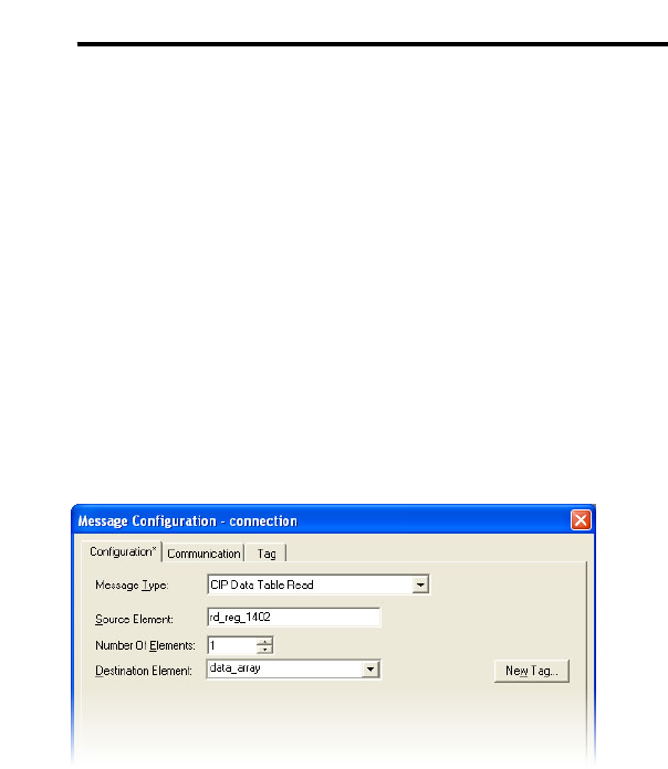
82
ICC
c) Expand the data_array tag. Refer to Figure 83.
d) 25 register values starting at register #11 are being continuously read
from the interface card and placed in the 25 sequential offsets of
data_array starting at the 11th offset (data_array[10]). In Figure 83, we
can see that data_array[10] (deceleration time #1) has a value of 100
(10.0s), data_array[11] (maximum frequency) has a value of 8000
(80.00Hz) etc.
13.2.7 ControlLogix Example: Read a Single Register
The configuration and execution for reading a single register is in general
identical to that required for reading a block of registers as detailed in section
13.2.6. The only difference is in the configuration of the MSG instruction.
Figure 84 shows an example MSG instruction’s Configuration tab, which will
read a single tag (rd_reg_1402, which corresponds to the drive’s “inverter
status 1” register) and place it in the first element (offset 0) of data_array.
Figure 84: Read the Drive’s Status Register
13.2.8 ControlLogix Example: Multiple MSG Instructions
At times, reading from different groups of registers may be necessary. For
example, a specific application may require some registers located in various
disjoint locations in the register map. To accomplish this task efficiently,
multiple MSG instructions can be implemented in the PLC program.
The configuration and execution for implementing multiple MSG instructions is
in general identical to that required for implementing just one MSG instruction.
Each MSG instruction will require its own message controller tag. In the case
of read MSG instructions, more than one instruction may use the same
Destination Element tag, but the storage locations must not overlap. Figure 85
shows an example of two MSG instructions, each accessing different read tags.
It is evident from this logic that “rd_connection” and “rd_connection2” are the
two independent message controller tags created for these instructions.
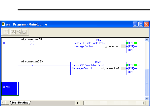
83
ICC
Figure 85: Reading Via Multiple MSG Instructions
13.2.9 ControlLogix Example: Reading and Writing
Often times, applications may need to both read data from and write data to the
drive. At a minimum, this will require two MSG instructions and two message
controller tags. Figure 86 shows an example of two MSG instructions, one for
reading and one for writing. The only item of note that differentiates this
example from the multiple-read example in section 13.2.8 is the addition of the
en_wr XIC element. The reason for the addition of this element is that while
reading from a remote device is often continuously performed (monitoring),
data is typically written to the remote device only when necessary (i.e. when the
value to write has changed). This conserves both network bandwidth and
potentially EEPROM lifespans on the target device. The en_wr element in this
example, therefore, would typically be replaced in an actual application program
by user-provided logic which controls the conditions under which a write
operation would be performed.
Figure 87 shows the configuration details of the example wr_connection MSG
instruction. Note that the chosen “Message Type” is “CIP Data Table Write”,
and that this instruction will only be writing to one drive register: namely, the
frequency command (Destination Element is wr_reg_1008). The Source
Element in this case is the 8th element (starting from index 0) of an INT array
tag named “wr_data_array”.
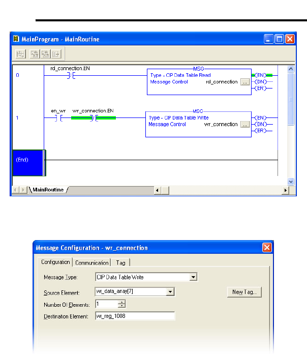
84
ICC
Figure 86: Reading and Writing via MSG Instructions
Figure 87: MSG Configuration for Writing

85
ICC
13.3 PCCC
Ethernet-enabled Allen-Bradley legacy PLCs (such as the PLC5E and SLC-
5/05 series) use a protocol called PCCC (Programmable Controller
Communication Commands) to communicate over the Ethernet network. The
interface card supports PCCC for direct connectivity to these PLCs.
If a connection timeout or socket-level error occurs, the driver will trigger a
timeout event as described in section 10.7.4.
13.3.1 Tag Reference
Register contents are read from and written to the interface card via PCCC by
reference to an integer “file/section number” and an “offset/element” within that
file. Reading is performed via the PCCC “PLC5 Read” (DF1 protocol typed
read) service, and writing is performed via the PCCC “PLC5 Write” (DF1
protocol typed write) service.
The formula to calculate which register is targeted in the interface card is
provided in Equation 3.
(
)
offset10010- number fileregister target +×= Equation 3
In Equation 3, “target register” ∈[1…1485], “file number” ∈[10…24] (which
means N10…N24), and “offset” is restricted only by the limitations of the
programming software (but is a value of 1485 max). Table 5 provides some
examples of various combinations of file/section numbers and offsets/elements
which can be used to access drive registers. Note that there are multiple
different combinations of file/section numbers and offsets/elements that will
result in the same drive register being accessed.
Table 5: PCCC Target Register Examples
File/Section
Number Offset/Element Start Target
Register
N10 1 1
N12 99 299
N11 199 299
N20 7 1007
N24 85 1485
N10 1485 1485
In addition to providing access to the drive registers in their “standard”
numerical locations as mentioned above, the registers can also be accessed in
a special “assembly object” type format by targeting integer file N50. What this
means is that when N50 is targeted for reading, what is actually returned by the
interface card is the user-defined register data as ordered by the EtherNet/IP
produced register configuration array (refer to section 10.8.4). Similarly, when

86
ICC
N50 is targeted for writing, the written data is disseminated to the drive’s
registers according to the definition contained in the EtherNet/IP consumed
register configuration array. By appropriate configuration of the EtherNet/IP
consumed and produced register configuration arrays, therefore, bulk access to
non-contiguous but frequently-used drive registers can be conveniently
provided by performing only one read and/or write instruction targeting file N50.
Because both the EtherNet/IP consumed and produced register configuration
arrays are comprised of 32 register definitions, the targeted “offset/element”
must be within the range of 0 to 31 inclusive. Refer to Table 6 for some
examples of N50 accesses.
Table 6: Examples of EtherNet/IP-Style Bulk Access via File N50
Offset/Element Start Target Register of
Configuration Array Max Number of
Accessible Elements
0 1st 32
: : :
15 16th 16
: : :
31 32nd 1
The application PLC program uses a MSG instruction that is configured with a
“Data Table Address” from which to start the access and a “Size in Elements”
which determines the number of items to access (read or write). The “Data
Table Address” is constructed by selecting a “File/Section Number” and an
“Offset/Element” according to Equation 3. For example, a “File/Section
Number” of N23 and “Offset/Element” of 5 = N23:5, which corresponds to
register 1305 (the drive’s input voltage monitor register).
13.3.2 SLC-5/05 Example: Read a Register Block
This example program will show how to continuously read a block of registers
from the drive with a single MSG instruction. Only one read request is
outstanding at any given time.
1) Run RSLogix 500, and create a new configuration.
2) Create a control and a data file.
a) Right click Data Files and select New… The “Create Data File” dialog
box appears (refer to Figure 88).
b) To create a control file, enter a file number (e.g. 20), set the type to
“Integer”, enter a descriptive name (e.g. “CONTROL”), and enter a
number of elements (e.g. 100). Click OK to create the file. The
control file is used to store configuration information pertaining to the
functionality of the MSG instruction which will perform the data read.
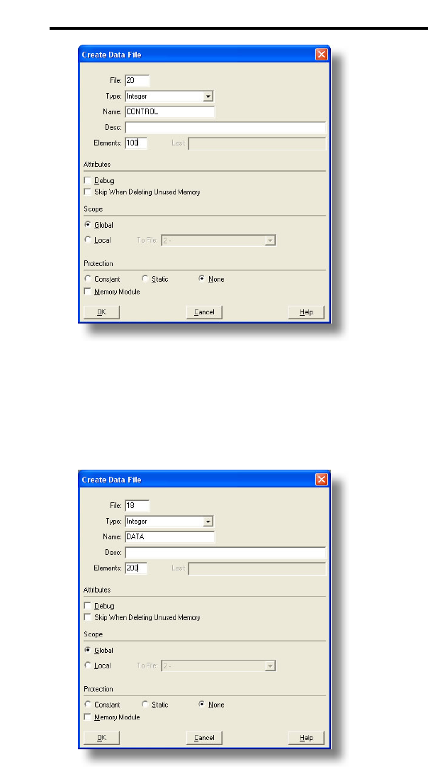
87
ICC
Figure 88: Creating a Control File
c) Follow the same procedure to create a data file. This file will be used
to store the incoming data read from the interface card. Enter a file
number (e.g. 18), set the type to “Integer”, enter a descriptive name
(e.g. “DATA”), and enter a number of elements (e.g. 200). Refer to
Figure 89. Click OK to create the file.
Figure 89: Creating a Data File
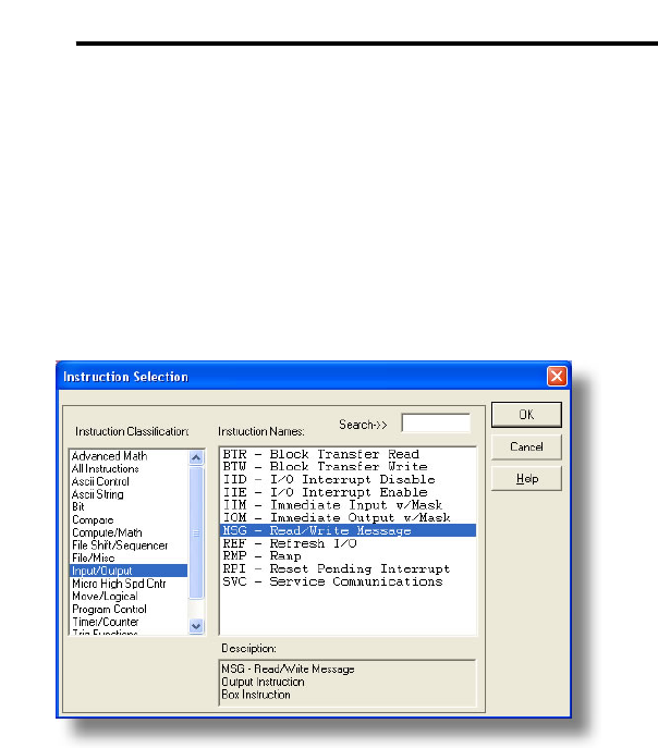
88
ICC
3) Add a MSG instruction to the program.
a) If not already visible, double-click “LAD2” under Project…Program
Files in the controller organizer view to bring up the ladder logic
program.
b) Right click on the default rung number on the left-hand side of the
LAD2 window and select “Insert Rung”.
c) Right click on the rung number of the new editable rung and select
“Append Instruction”.
d) Select the “MSG” instruction from the “Input/Output” classification,
then click OK. Refer to Figure 90.
Figure 90: MSG Instruction Selection
4) Add an XIO element to the program.
a) Right click on the rung number of the rung currently being edited and
select “Append Instruction” again.
b) Select the “XIO” instruction from the “Bit” classification, then click OK.
Refer to Figure 91.
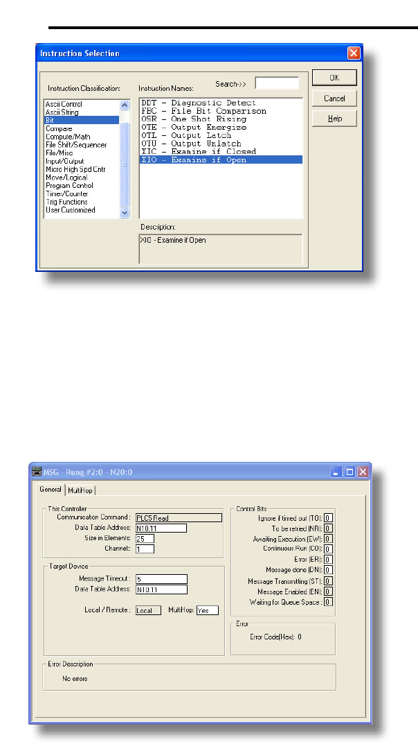
89
ICC
Figure 91: XIO Instruction Selection
5) Configure the MSG instruction.
a) Set the “Read/Write” field to “Read”, “Target Device” field to “PLC5”,
“Local/Remote” field to “Local”, and “Control Block” to “N20:0”.
b) Upon hitting the <ENTER> key while in the “Control Block” entry box,
the MSG Properties dialog box should appear (or it can be opened by
clicking on the “Setup Screen” button at the bottom of the MSG
instruction). Refer to Figure 92.
Figure 92: MSG Configuration, "General" Tab
90
ICC
c) In this example, we will be reading a total of 25 registers beginning at
N10:11 (register 11, the drive’s “deceleration time 1” parameter). To
configure this, under “This Controller” set the “Data Table Address”
field to N18:11, set the “Size in Elements field” to 25, and set the
“Channel” field to 1 (Ethernet).
d) Under “Target Device”, set the “Data Table Address” field to N10:11
(starting target register=11) and set the “MultiHop” field to Yes to
cause the “MultiHop” tab to appear.
e) Under the “MultiHop” tab settings, set the “To Address” in the first row
to the drive’s IP address, and the “To Address” in the second row to 0.
Refer to Figure 93.
Figure 93: MSG Configuration, "MultiHop" Tab
f) Close the dialog box. At this point, the program should appear as
shown in Figure 94.
Figure 94: PLC Program after MSG Instruction Configuration
6) Assign a tag to the XIO element.
a) Double-click on the XIO element located to the left of the MSG block.
Type in N20:0/15 (MSG instruction’s enable bit). This configuration
91
ICC
causes the MSG instruction to automatically retrigger itself when it
completes. While this is acceptable for the purposes of this example,
it can produce high network utilization. In actual practice, it may be
desirable to incorporate additional logic elements to allow triggering
the MSG instruction at a specific rate or under specific conditions.
7) The program is now complete. Refer to Figure 95.
Figure 95: Completed PLC Program
8) Save, download, and run the program.
a) To view the registers being read from the interface card, double-click
the data file N18 under “Data Files” in the controller organizer view.
25 register values starting at register #11 are being continuously read
from the interface card and placed in the 25 sequential offsets of N18
starting at N18:11. Refer to Figure 96. We can see that N18:11
(deceleration time #1) has a value of 100 (10.0s), N18:12 (maximum
frequency) has a value of 6000 (60.00Hz), etc.
Figure 96: Monitoring the Data Being Read from the Drive
92
ICC
13.3.3 SLC-5/05 Example: Read a Single Register
The configuration and execution for reading a single register is in general
identical to that required for reading a block of registers as detailed in section
13.3.2. The only difference is in the configuration of the MSG instruction.
Figure 97 shows an example MSG instruction’s General tab, which will read a
single element (N24:2, which corresponds to the drive’s “inverter status 1”
register) and place it in the first element (offset 0) of N18.
Figure 97: Read the Drive’s Status Register
13.3.4 SLC-5/05 Example: Multiple MSG Instructions
At times, reading from different groups of registers may be necessary. For
example, a specific application may require some registers located in various
disjoint locations in the register map. To accomplish this task efficiently,
multiple MSG instructions can be implemented in the PLC program.
The configuration and execution for implementing multiple MSG instructions is
in general identical to that required for implementing just one MSG instruction.
Each MSG instruction will require its own message control file. In the case of
read MSG instructions, more than one instruction may use the same data file to
store the received register values, but the storage locations must not overlap.
Figure 98 shows an example of two MSG instructions, each accessing different
target integer files. It is evident from this logic that N20 and N21 are the two
independent message control files created for these instructions.
93
ICC
Figure 98: Reading Via Multiple MSG Instructions
13.3.5 SLC-5/05 Example: Reading and Writing
Often times, applications may need to both read data from and write data to the
drive. At a minimum, this will require two MSG instructions and two message
control files. Figure 99 shows an example of two MSG instructions, one for
reading and one for writing. Note that the “Read/Write” field of each of the
MSG instructions is set according to their function.
Figure 100 shows the configuration details of the “write” MSG instruction. Note
that this instruction will only be writing to one drive register: namely, the
frequency command (Target Data Table Address is N20:8, which equates to
drive register 1008). The source Data Table Address in this case is N18:7.
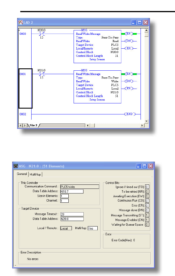
94
ICC
Figure 99: Reading and Writing via MSG Instructions
Figure 100: MSG Configuration for Writing

95
ICC
13.4 BACnet
13.4.1 Overview
• The interface card supports the BACnet/IP (Annex J) protocol over
Ethernet via UDP port 47808.
• The BACnet driver does not trigger timeout events (section 10.7.4).
13.4.2 Protocol Implementation Conformance Statement
BACnet Protocol
Date: August 20, 2008
Vendor Name: ICC, Inc.
Product Name: Ethernet interface for Toshiba G9/AS1 ASD
Product Model Number: ASD-G9ETH
Applications Software Version: V2.100
Firmware Revision: V2.100
BACnet Protocol Revision: 2
Product Description:
The Toshiba G9/AS1 is an advanced inverter featuring reduced high-
frequency noise, reduced harmonics, and high-precision and high-
speed torque control with or without sensors.
BACnet Standard Device Profile (Annex L):
BACnet Operator Workstation (B-OWS)
BACnet Building Controller (B-BC)
BACnet Advanced Application Controller (B-AAC)
BACnet Application Specific Controller (B-ASC)
BACnet Smart Sensor (B-SS)
BACnet Smart Actuator (B-SA)
BACnet Interoperability Building Blocks Supported (Annex K):
Data Sharing – ReadProperty-B (DS-RP-B)
Data Sharing – ReadPropertyMultiple-B (DS-RPM-B)
Data Sharing – WriteProperty-B (DS-WP-B)
Device Management – Dynamic Device Binding-B (DM-DDB-B)
Device Management – Dynamic Object Binding-B (DM-DOB-B)
Segmentation Capability:
None
Segmented requests supported Window Size ________

96
ICC
Segmented responses supported Window Size ________
Standard Object Types Supported:
See “Object Types/Property Support Table”.
Data Link Layer Options:
BACnet IP, (Annex J)
BACnet IP, (Annex J), Foreign Device
ISO 8802-3, Ethernet (Clause 7)
ANSI/ATA 878.1, 2.5 Mb. ARCNET (Clause 8)
ANSI/ATA 878.1, RS-485 ARCNET (Clause 8), baud rate(s) ______
MS/TP master (Clause 9), baud rate(s): 9600, 19200, 38400, 76800
MS/TP slave (Clause 9), baud rate(s): ______
Point-To-Point, EIA 232 (Clause 10), baud rate(s): ______
Point-To-Point, modem, (Clause 10), baud rate(s): ______
LonTalk, (Clause 11), medium: ______
Other: ______
Device Address Binding:
Is static device binding supported? (This is currently for two-way
communication with MS/TP slaves and certain other devise.) Yes No
Networking Options:
Router, Clause 6 - List all routing configurations
Annex H, BACnet Tunneling Router over IP
BACnet/IP Broadcast Management Device (BBMD)
Does the BBMD support registrations by Foreign Devices? Yes No
Character Sets Supported:
Indicating support for multiple character sets does not imply that they can all be
supported simultaneously.
ANSI X3.4 IBM™/Microsoft™ DBCS ISO 8859-1
ISO 10646 (UCS-2) ISO 10646 (UCS-4) JIS C 6226
If this product is a communication gateway, describe the types of non-BACnet
equipment/networks(s) that the gateway supports: N/A

97
ICC
Datatypes Supported:
The following table summarizes the datatypes that are accepted (in the case of
a write property service) and returned (in the case of a read property service)
when targeting the present value property of each supported object type.
Service
Object Type Read Property Write Property
Analog Output Real Real, Unsigned, Integer, Null
Analog Input Real N/A
Binary Output Enumerated Enumerated, Boolean, Real, Unsigned,
Integer, Null
Binary Input Enumerated N/A
Notes:
• The Null data type is used to relinquish a previously-commanded entry at
the targeted priority in the priority array.
• When writing to Binary Output objects, all non-zero values are interpreted
as a “1”.

98
ICC
Object Types/Property Support Table
The following table summarizes the Object Types/Properties supported.
Object Type
Property Device Binary
Input Binary
Output Analog
Input Analog
Output
Object Identifier R R R R R
Object Name R R R R R
Object Type R R R R R
System Status R
Vendor Name R
Vendor Identifier R
Model Name R
Firmware Revision R
Appl Software Revision R
Protocol Version R
Protocol Revision R
Services Supported R
Object Types Supported R
Object List R
Max APDU Length R
Segmentation Support R
APDU Timeout R
Number APDU Retries R
Max Master
Max Info Frames
Device Address Binding R
Database Revision R
Present Value R W R W
Status Flags R R R R
Event State R R R R
Reliability R R R R
Out-of-Service R R R R
Units R R
Priority Array R R
Relinquish Default R R
Polarity R R
Active Text R R
Inactive Text R R
R – readable using BACnet services
W – readable and writable using BACnet services

99
ICC
13.4.3 Supported Objects
Binary Input Object Instance Summary
Instance
ID Object Name Description Active/
Inactive Text
BI1 RUN_STOP_STATUS Run/stop status running/
stopped
BI2 FWD_REV_STATUS Forward/reverse status reverse/
forward
BI3 F_PIT_STATUS "F" programmable
input terminal status on/off
BI4 R_PIT_STATUS "R" programmable
input terminal status on/off
BI5 ST_PIT_STATUS "ST" programmable
input terminal status on/off
BI6 RES_PIT_STATUS "RES" programmable
input terminal status on/off
BI7 S1_PIT_STATUS "S1" programmable
input terminal status on/off
BI8 S2_PIT_STATUS "S2" programmable
input terminal status on/off
BI9 S3_PIT_STATUS "S3" programmable
input terminal status on/off
BI10 S4_PIT_STATUS "FS4" programmable
input terminal status on/off
BI11 OUT1_POT_STATUS "OUT1" programmable
input terminal status on/off
BI12 OUT2_POT_STATUS "OUT2" programmable
input terminal status on/off
BI13 FL_POT_STATUS "FL" programmable
input terminal status on/off

100
ICC
Binary Output Object Instance Summary
Instance
ID Object Name Description Active/
Inactive Text
BO1 RUN_STOP_CMD Run/stop command run/stop
BO2 FWD_REV_SEL Forward/reverse
command reverse/forward
BO3 EMERGENCY_OFF Emergency off
command emergency off/
no action
BO4 FAULT_RESET Fault reset command reset/no action
BO5 FEEDBACK_CTRL_SEL
Feedback enable/
disable selection enable/disable
BO6 FREQ_PRIORITY Frequency priority on/off
BO7 COMMAND_PRIORITY Command priority on/off
BO8 DATA_OUT1_TERMINAL Output terminal
“selected data out 1” on/off
BO9 DATA_OUT2_TERMINAL Output terminal
“selected data out 2” on/off
BO10 DATA_OUT3_TERMINAL Output terminal
“selected data out 3” on/off
Analog Input Object Instance Summary
Instance ID Object Name Description Units
AI1 OUTPUT_FREQ Output frequency Hz
AI2 LOAD_CURRENT Output current Percent
AI3 OUTPUT_VOLTAGE Output voltage Percent
AI4 INPUT_POWER_CONSUME Input power KW
AI5 RR_ANALOG_INPUT RR/S4 input Percent
AI6 VI_II_ANALOG_INPUT VI/II input Percent
AI7 RX_ANALOG_INPUT RX input Percent
AI8 TRIP_CODE Trip code information None
Analog Output Object Instance Summary
Instance ID Object Name Description Units
AO1 FREQ_CMD_REG Frequency command Hz
AO2 FM_ANALOG OUTPUT FM output value None
AO3 AM_ANALOG OUTPUT AM output value None

101
ICC
13.4.4 Supported Object Details
Binary Input Objects
BI1 ........Indicates whether the drive is running or stopped. ASD parameter
FE01, bit#10.
BI2 ........Indicates whether the drive is running in the forward or reverse
direction. ASD parameter FE01, bit #9.
BI3 ........Indicates the status of the "F" programmable input terminal. ASD
parameter FE06, bit#0.
BI4 ........Indicates the status of the "R" programmable input terminal. ASD
parameter FE06, bit#1.
BI5 ........Indicates the status of the "ST" programmable input terminal. ASD
parameter FE06, bit#2.
BI6 ........Indicates the status of the "RES" programmable input terminal. ASD
parameter FE06, bit#3.
BI7 ........Indicates the status of the "S1" programmable input terminal. ASD
parameter FE06, bit#4.
BI8 ........Indicates the status of the "S2" programmable input terminal. ASD
parameter FE06, bit#5.
BI9 ........Indicates the status of the "S3" programmable input terminal. ASD
parameter FE06, bit#6.
BI10 ......Indicates the status of the "S4" programmable input terminal. ASD
parameter FE06, bit#7.
BI11 ......Indicates the status of the "OUT1" programmable output terminal.
ASD parameter FE07, bit#0.
BI12 ......Indicates the status of the "OUT2" programmable output terminal.
ASD parameter FE07, bit#1.
BI13 ......Indicates the status of the "FL" programmable output terminal. ASD
parameter FE07, bit#2.
Binary Output Objects
Note that the drive will only use the commands indicated in BO1, BO2 and BO5
if the Command Mode parameter is set to "Communication Interface Input
Enabled", or if the "command override" bit (BO7) is ON.
BO1 ......Run/stop command. ASD parameter FA06, bit#10.
BO2 ......Forward/reverse command. ASD parameter FA06, bit#9.
BO3 ......Forces the drive to fault "Emergency Off". ASD parameter FA06,
bit#12.

102
ICC
BO4...... Resets the drive when it is faulted. ASD parameter FA06, bit#13.
BO5...... Enables or disables process (PID) feedback control. Note that this
object does not activate (turn on) feedback control. It only enables or
disables feedback control once it has already been activated. ASD
parameter FA06, bit#5.
BO6...... Communication interface frequency priority selection. Allows the
frequency command from the interface card to be used by the drive
without having to set the Frequency Mode parameter. Refer to the
Toshiba documentation regarding "Command Mode and Frequency
Mode Control" for detailed information pertaining to the frequency
source hierarchy and the use of overrides. ASD parameter FA06,
bit#14.
BO7...... Communication interface command priority selection. Allows
commands (BO1, BO2, and BO5) from the interface card to be used
by the drive without having to explicitly set the Command Mode
parameter. Refer to the Toshiba documentation regarding "Command
Mode and Frequency Mode Control" for detailed information pertaining
to the command source hierarchy and the use of overrides. ASD
parameter FA06, bit#5.
BO8...... Output terminal data out 1. Any programmable output terminals that
are configured to output “specified data output 1” will follow the value
of this BO. ASD parameter FA50, bit#0.
BO9...... Output terminal data out 2. Any programmable output terminals that
are configured to output “specified data output 2” will follow the value
of this BO. ASD parameter FA50, bit#1.
BO10.... Output terminal data out 3. Any programmable output terminals that
are configured to output “specified data output 3” will follow the value
of this BO. ASD parameter FA50, bit#2.
Analog Input Objects
AI1........ Output frequency in 0.01Hz units. ASD parameter FD00.
AI2........ Load current in 0.01% units (10000=100.00%=drive's rated current).
ASD parameter FE03.
AI3........ Output voltage in 0.01% units (10000=100.00%=drive's rated voltage).
ASD parameter FE05.
AI4........ Input power consumption (drive+motor) in 0.01kW units. ASD
parameter FE29.
AI5........ Indicates the signal level currently being applied to the ASD's RR
analog input terminal. This can be used to monitor such items as
feedback sensor outputs and other process variables. Expressed in
0.01% units (10000=100.00%=input rated value). ASD parameter
FE35.

103
ICC
AI6 ........Similar to AI5, this object indicates the signal level currently being
applied to the ASD's VI/II analog input terminal. ASD parameter
FE36.
AI7 ........Similar to AI5, this object indicates the signal level currently being
applied to the ASD's RX analog input terminal. ASD parameter FE37.
AI8 ........Indicates the present fault code. Under normal operation (no faults),
this value will be 0. ASD parameter FC90.
Analog Output Objects
AO1 ......Sets the drive's frequency command in 0.01Hz units (e.g. 4000 =
40.00Hz). Note that the drive will only use this value as its active
frequency command if the Frequency Mode parameter is set to
“Communication Option Input Enabled ", or if the "frequency override"
bit (BO6) is ON. Although the adjustment range for this object is 0-
40000 (0.00Hz-400.00Hz), the actual frequency command will be
internally limited by the Upper Limit Frequency and Lower Limit
Frequency parameters. ASD parameter FA07.
AO2 ......Adjusts the FM analog output voltage if the “FM terminal meter
selection” parameter is set to a value of 31 (communication data
output). Range is 0-2047 = 0-100%. ASD parameter FA51.
AO3 ......Adjusts the AM analog output voltage if the “AM terminal meter
selection” parameter is set to a value of 31 (communication data
output). Range is 0-2047 = 0-100%. ASD parameter FA52.

104
ICC
13.5 Profinet IO
• Up to 8 command registers can be sent to the drive, and up to 32 status
registers can be retrieved from the drive.
• A total of 84 modules are available for selection by the controller. Refer to
the GSDML file for specific module information.
• No explicit module selection is required on the interface card: the module
will be selected automatically according to the controller’s configuration.
• The Profinet IO driver does not trigger timeout events (section 10.7.4).
ICC
INDUSTRIAL CONTROL COMMUNICATIONS, INC.
Madison Office Houston Office
1600 Aspen Commons, Suite 210 12300 Dundee Court, Suite 212
Middleton, WI USA 53562-4720 Cypress, TX USA 77429-8364
Tel: [608] 831-1255 Fax: [608] 831-2045
http://www.iccdesigns.com Printed in U.S.A
ASD INTERFACE SERIES
ICC
INDUSTRIAL CONTROL COMMUNICATIONS, INC.
ASD-G9ETH
MULTIPROTOCOL ETHERNET INTERFACE FOR
TOSHIBA G9 / VFAS1 ADJUSTABLE SPEED DRIVES
August 2008
ICC #10639-2.100-000
