Trane Voyager Commercial 27 5 To 50 Tons Installation And Maintenance Manual Installation, Operation,
2015-04-02
: Trane Trane-Voyager-Commercial-27-5-To-50-Tons-Installation-And-Maintenance-Manual-684193 trane-voyager-commercial-27-5-to-50-tons-installation-and-maintenance-manual-684193 trane pdf
Open the PDF directly: View PDF ![]() .
.
Page Count: 138 [warning: Documents this large are best viewed by clicking the View PDF Link!]
- Warnings, Cautions and Notices
- Table of Contents
- Model Number Description
- General Information
- Unit Dimensions and Weights
- Installation General Requirements
- Installation Electrical
- Installation Piping
- Startup
- Unit Control Modules
- RTRM - ReliaTel™ Refrigeration Module
- ECA/RTEM - Economizer Actuator/ReliaTel Economizer Module (Optional)
- EBA - Exhaust Blade Actuator (Optional)
- RTAM - ReliaTel Air Handler Module (Standard with Traditional VAV)
- ReliaTel Ventilation Module (RTVM)
- ReliaTel Dehumidification Module (RTDM)
- Conventional Thermostat Connections (Available Only with CV)
- TCI - Trane Communication Interface (Optional)
- LCI - LonTalk® Communication Interface (Optional)
- BCI - BACnet® Communication Interface (Optional)
- Trane Wireless Comm Interface (WCI)
- TD5 Display - 5" Touchscreen Display
- System Operation
- Economizer Operation with a Conventional Thermostat (CV Only)
- Microelectronic Control Features
- Economizer Operation with CV Controls
- Modulating Power Exhaust
- Mechanical Cooling without an Economizer (CV and SZ VAV)
- Zone Temperature - Occupied Cooling (CV and SZ VAV)
- Zone Temperature - Occupied Heating (CV and SZ VAV)
- Supply Fan (CV and SZ VAV)
- Supply Air Tempering (CV and SZ VAV)
- Variable Air Volume Applications (Single Zone VAV)
- Variable Air Volume Applications (Traditional VAV)
- Supply Air Temperature Control - Occupied Cooling and Heating
- Supply Air Temperature Control with an Economizer
- VHR Relay Output
- Zone Temperature Control without a Night Setback Panel or ICS - Unoccupied Cooling
- Zone Temperature Control without a Night Setback Panel or ICS - Unoccupied Heating
- Morning Warm-up (MWU) Control
- Daytime Warm-up (DWU) Control
- Supply Duct Static Pressure Control
- Supply Air Temperature Reset
- VAV Supply Air Tempering (Only Available with Modulating Gas Heat)
- Constant Volume or Variable Air Volume Applications (Single Zone or Traditional)
- Off Mode
- Zone Temperature - Unoccupied Cooling (CV or SZ VAV Only)
- Zone Temperature - Unoccupied Heating
- Mechanical Cooling with an Economizer
- Gas Heat Control
- Electric Heat Control
- Clogged Filter Option
- Ventilation Override
- Emergency Stop
- Phase Monitor
- Low Pressure Control
- Dehumidification Low Pressure Control
- High Pressure Cutout and Temperature Discharge Limit
- Power Exhaust Control (Standard)
- Space Pressure Control - Statitrac
- Power Exhaust Control (Tracking)
- Lead/Lag Control
- Coil Frost Protection
- Dehumidification Frost Protection
- Drain Pan Condensate Overflow Switch (Optional)
- VFD Programming Parameters
- Condenser Fan Sequencing Control
- Preparing the Unit for Operation
- Starting the Unit
- Economizer Damper Adjustment
- Starting the Compressor
- Gas Heat Units
- Electric Heat Units
- Final Unit Checkout
- Unit Control Modules
- Pre-Installation
- Sequence of Operation
- Mechanical Cooling Sequence Of Operation
- Dehumidification (Modulating Hot Gas Reheat) Sequence of Operation
- Gas Heat Sequence Of Operation
- Electric Heat Sequence Of Operation
- Variable Air Volume Applications (Single Zone VAV) Sequence of Operation
- Low Pressure Control (LPC) Sequence of Operation (ReliaTel Control)
- High Pressure Control and Temperature Discharge Limit (ReliaTel Control)
- Maintenance
- Diagnostics
- System Status/Diagnostics
- Terminal locations
- System Status / Diagnostics checkout procedure (DC volt meter required)
- Diagnostics (CV and SZ VAV Units Only)
- Diagnostics (VAV only)
- Resetting Cooling and Ignition Lockouts
- Zone Temperature Sensor (ZSM) Service Indicator
- RTRM Zone Sensor Module (ZSM) Tests
- Programmable & Digital Zone Sensor Test
- ReliaTel Refrigeration Module (RTRM)
- Economizer Actuator (ECA/RTEM) Test Procedures
- ReliaTel Air Module (RTAM) Tests
- ReliaTel Air Module (RTOM) Tests
- Compressor—Blink Codes
- Troubleshooting
- TR-200 VFD Programming Parameters
- System Status/Diagnostics
- Unit Wiring Diagram Numbers
- Warranty and Liability Clause
SAFETY WARNING
Only qualified personnel should install and service the equipment. The installation, starting up, and servicing of heating, ventilating, and air-
conditioning equipment can be hazardous and requires specific knowledge and training. Improperly installed, adjusted or altered equipment
by an unqualified person could result in death or serious injury. When working on the equipment, observe all precautions in the literature and
on the tags, stickers, and labels that are attached to the equipment.
Voyager™ Commercial
27.5 to 50 Ton 60 Hz
22.9 to 41.7 Ton 50 Hz
CV, VAV, or SZ VAV Rooftop Air Conditioners
with ReliaTel™ Controls, R-410A Refrigerant
Installation, Operation,
and Maintenance
Model Numbers
“B” and later design sequence
TC*, TE*, YC*330B, 360B, 420B, 480B, 600B (60 Hz/3 phase)
TC*, TE*, YC*275B, 305B, 350B, 400B, 500B (50 Hz/3 phase)
Proprietary and Confidential
RT-SVX34H-EN
June 2014
© 2014 Trane All rights reserved RT-SVX34H-EN
Warnings, Cautions and Notices
Warnings, Cautions and Notices. Note that warnings,
cautions and notices appear at appropriate intervals
throughout this manual. Warnings are provided to alert
installing contractors to potential hazards that could result
in personal injury or death. Cautions are designed to alert
personnel to hazardous situations that could result in
personal injury, while notices indicate a situation that could
result in equipment or property-damage-only accidents.
Your personal safety and the proper operation of this
machine depend upon the strict observance of these
precautions.
Important
Environmental Concerns!
Scientific research has shown that certain man-made
chemicals can affect the earth’s naturally occurring
stratospheric ozone layer when released to the
atmosphere. In particular, several of the identified
chemicals that may affect the ozone layer are refrigerants
that contain Chlorine, Fluorine and Carbon (CFCs) and
those containing Hydrogen, Chlorine, Fluorine and Carbon
(HCFCs). Not all refrigerants containing these compounds
have the same potential impact to the environment. Trane
advocates the responsible handling of all refrigerants-
including industry replacements for CFCs such as HCFCs
and HFCs.
Responsible Refrigerant Practices!
Trane believes that responsible refrigerant practices are
important to the environment, our customers, and the air
conditioning industry. All technicians who handle
refrigerants must be certified. The Federal Clean Air Act
(Section 608) sets forth the requirements for handling,
reclaiming, recovering and recycling of certain refrigerants
and the equipment that is used in these service procedures.
In addition, some states or municipalities may have
additional requirements that must also be adhered to for
responsible management of refrigerants. Know the
applicable laws and follow them.
Overview of Manual
One copy of the appropriate service literature ships inside
the control panel of each unit. The procedures discussed in
this manual should only be performed by qualified,
experienced HVAC technicians.
Note: Do not release refrigerant to the atmosphere! If
adding or removing refrigerant is required, the
service technician must comply with all federal,
state, and local laws.
This booklet describes the proper installation, startup,
operation, and maintenance procedures for TC_, TE_, and
YC_22.9 to 50 Ton CV (Constant Volume), VAV (Variable Air
Volume), and SZ VAV (Single Zone Variable Air Volume)
applications. Refer to the table of contents for a listing of
specific topics. Refer to “Diagnostics,” p. 117 for
troubleshooting information.
ATTENTION: Warnings, Cautions and Notices appear at
appropriate sections throughout this literature. Read these
carefully:
WARNING Indicates a potentially hazardous
situation which, if not avoided, could
result in death or serious injury.
CAUTIONsIndicates a potentially hazardous
situation which, if not avoided, could
result in minor or moderate injury. It
could also be used to alert against
unsafe practices.
NOTICE: Indicates a situation that could result in
equipment or property-damage only
WARNING
Personal Protective Equipment (PPE)
Required!
Installing/servicing this unit could result in exposure to
electrical, mechanical and chemical hazards.
• Before installing/servicing this unit, technicians
MUST put on all Personal Protective Equipment (PPE)
recommended for the work being undertaken.
ALWAYS refer to appropriate MSDS sheets and OSHA
guidelines for proper PPE.
• When working with or around hazardous chemicals,
ALWAYS refer to the appropriate MSDS sheets and
OSHA guidelines for information on allowable
personal exposure levels, proper respiratory
protection and handling recommendations.
• If there is a risk of arc or flash, technicians MUST put
on all Personal Protective Equipment (PPE) in
accordance with NFPA 70E or other country-specific
requirements for arc flash protection, PRIOR to
servicing the unit.
Failure to follow instructions could result in death or
serious injury.
WARNING
Proper Field Wiring and Grounding
Required!
All field wiring MUST be performed by qualified
personnel. Improperly installed and grounded field
wiring poses FIRE and ELECTROCUTION hazards. To
avoid these hazards, you MUST follow requirements for
field wiring installation and grounding as described in
NEC and your local/state electrical codes. Failure to
follow code could result in death or serious injury.
Warnings, Cautions and Notices
RT-SVX34H-EN 3
By carefully reviewing the information within this manual
and following the instructions, the risk of improper
operation and/or component damage will be minimized.
It is important that periodic maintenance be performed to
help assure trouble free operation. A maintenance
schedule is provided at the end of this manual. Should
equipment failure occur, contact a qualified service
organization with qualified, experienced HVAC technicians
to properly diagnose and repair this equipment.
Revision History
RT-SVX34G-EN (3 June 2014)
• Added features: Low Leak Damper option, eStage,
Ultra Low Leak Power Exhaust, Touchscreen Human
Interface.
• Updated Model Number Description, Startup,
Sequence of Operation, Diagnostics, Unit Wiring
Diagrams.
60 Hz units with standard options are certified by
Underwriters Laboratory.

4 RT-SVX34H-EN
Table of Contents
Model Number Description . . . . . . . . . . . . . . . 8
60 Hz Description . . . . . . . . . . . . . . . . . . . . . . 8
50 Hz Description . . . . . . . . . . . . . . . . . . . . . 10
General Information . . . . . . . . . . . . . . . . . . . . 12
Commonly Used Acronyms and Abbrevia-
tions . . . . . . . . . . . . . . . . . . . . . . . . . . . . . . 12
About the Unit . . . . . . . . . . . . . . . . . . . . . 12
Precautionary Measures . . . . . . . . . . . . . 13
Unit Inspection . . . . . . . . . . . . . . . . . . . . . 13
Storage . . . . . . . . . . . . . . . . . . . . . . . . . . . 13
Unit Dimensions and Weights . . . . . . . . . . . 14
Recommended Clearances . . . . . . . . . . . . . 14
Roof Curb and Ductwork . . . . . . . . . . . . . . . 14
Horizontal Ductwork . . . . . . . . . . . . . . . . . 14
Unit Rigging and Placement . . . . . . . . . . . 20
Installation General Requirements . . . . . . . 23
Condensate Drain Connection . . . . . . . . . . 23
Condensate Overflow Switch . . . . . . . . . . . 23
O/A Sensor & Tubing Installation . . . . . . . 23
Units with Statitrac™ . . . . . . . . . . . . . . . . . 23
Installation Electrical . . . . . . . . . . . . . . . . . . . . 25
Disconnect Switch External Handle (Factory
Mounted Option) . . . . . . . . . . . . . . . . . . . . . 25
Main Power Wiring . . . . . . . . . . . . . . . . . . . 25
Through-the-Base Electrical (Optional Acces-
sory) . . . . . . . . . . . . . . . . . . . . . . . . . . . . . . 26
Electrical Wire Sizing and Protection Device
Equations . . . . . . . . . . . . . . . . . . . . . . . . . . . . 29
Low Voltage Wiring . . . . . . . . . . . . . . . . . 30
Control Power Transformer . . . . . . . . . . . 30
Field Installed AC Control Wiring . . . . . . 30
Field Installed DC Control Wiring . . . . . . 31
Remote Panels and Sensors . . . . . . . . . . . 34
Constant Volume and Single Zone VAV Con-
trol Options . . . . . . . . . . . . . . . . . . . . . . . . 34
Variable Air Volume (non-SZ VAV) Control
Options . . . . . . . . . . . . . . . . . . . . . . . . . . . 34
Installation Piping . . . . . . . . . . . . . . . . . . . . . . 38
General Requirements . . . . . . . . . . . . . . . . 38
Connecting the Gas Supply Line to the Fur-
nace Gas Train . . . . . . . . . . . . . . . . . . . . . .38
Startup . . . . . . . . . . . . . . . . . . . . . . . . . . . . . . . . .40
Unit Control Modules . . . . . . . . . . . . . . . . . .40
RTRM - ReliaTel™ Refrigeration Module .40
ECA/RTEM - Economizer Actuator/ReliaTel
Economizer Module (Optional) . . . . . . . . .40
EBA - Exhaust Blade Actuator (Optional) .40
RTAM - ReliaTel Air Handler Module (Stan-
dard with Traditional VAV) . . . . . . . . . . . .40
ReliaTel Ventilation Module (RTVM) . . . .41
ReliaTel Dehumidification Module
(RTDM) . . . . . . . . . . . . . . . . . . . . . . . . . . . .42
Conventional Thermostat Connections
(Available Only with CV) . . . . . . . . . . . . . .42
TCI - Trane Communication Interface (Option-
al) . . . . . . . . . . . . . . . . . . . . . . . . . . . . . . . . .42
LCI - LonTalk® Communication Interface (Op-
tional) . . . . . . . . . . . . . . . . . . . . . . . . . . . . .42
BCI - BACnet® Communication Interface (Op-
tional) . . . . . . . . . . . . . . . . . . . . . . . . . . . . .42
Trane Wireless Comm Interface (WCI) . . .42
TD5 Display - 5" Touchscreen Display . . .42
System Operation . . . . . . . . . . . . . . . . . . . . .43
Economizer Operation with a Conventional
Thermostat (CV Only) . . . . . . . . . . . . . . . .43
Microelectronic Control Features . . . . . . .43
Economizer Operation with CV Controls .44
Modulating Power Exhaust . . . . . . . . . . . .44
Mechanical Cooling without an Economizer
(CV and SZ VAV) . . . . . . . . . . . . . . . . . . . .44
Zone Temperature - Occupied Cooling (CV
and SZ VAV) . . . . . . . . . . . . . . . . . . . . . . . .45
Zone Temperature - Occupied Heating (CV
and SZ VAV) . . . . . . . . . . . . . . . . . . . . . . . .45
Supply Fan (CV and SZ VAV) . . . . . . . . . .45
Supply Air Tempering (CV and SZ VAV) .45
Variable Air Volume Applications (Single
Zone VAV) . . . . . . . . . . . . . . . . . . . . . . . . . . . .46
Supply Fan Output Control . . . . . . . . . . . .46
Minimum Supply Fan Output . . . . . . . . . .46
Supply Fan Mode Operation . . . . . . . . . . .47

Table of Contents
RT-SVX34H-EN 5
Setpoint Arbitration . . . . . . . . . . . . . . . . . 47
Ventilation Control . . . . . . . . . . . . . . . . . . 50
Space Pressure Control . . . . . . . . . . . . . . 52
Traq Overrides and Special
Considerations . . . . . . . . . . . . . . . . . . . . . 53
Supply Air Temperature Control - Heating
and Cooling . . . . . . . . . . . . . . . . . . . . . . . . 53
Variable Air Volume Applications (Traditional
VAV) . . . . . . . . . . . . . . . . . . . . . . . . . . . . . . . . 53
Supply Air Temperature Control - Occupied
Cooling and Heating . . . . . . . . . . . . . . . . 53
Supply Air Temperature Control with an
Economizer . . . . . . . . . . . . . . . . . . . . . . . . 54
VHR Relay Output . . . . . . . . . . . . . . . . . . . 54
Zone Temperature Control without a
Night Setback Panel or ICS - Unoccupied
Cooling . . . . . . . . . . . . . . . . . . . . . . . . . . . 54
Zone Temperature Control without a
Night Setback Panel or ICS - Unoccupied
Heating . . . . . . . . . . . . . . . . . . . . . . . . . . . 54
Morning Warm-up (MWU) Control . . . . . 54
Daytime Warm-up (DWU) Control . . . . . 54
Supply Duct Static Pressure Control . . . 54
Supply Air Temperature Reset . . . . . . . . 55
VAV Supply Air Tempering (Only Available
with Modulating Gas Heat) . . . . . . . . . . . 55
Constant Volume or Variable Air Volume Ap-
plications (Single Zone or Traditional) . . . 55
Off Mode . . . . . . . . . . . . . . . . . . . . . . . . . . 55
Zone Temperature - Unoccupied Cooling (CV
or SZ VAV Only) . . . . . . . . . . . . . . . . . . . . 55
Zone Temperature - Unoccupied Heating 55
Mechanical Cooling with an Economizer 56
Gas Heat Control . . . . . . . . . . . . . . . . . . . 56
Electric Heat Control . . . . . . . . . . . . . . . . 56
Clogged Filter Option . . . . . . . . . . . . . . . . 56
Ventilation Override . . . . . . . . . . . . . . . . . 57
Emergency Stop . . . . . . . . . . . . . . . . . . . . 57
Phase Monitor . . . . . . . . . . . . . . . . . . . . . 57
Low Pressure Control . . . . . . . . . . . . . . . . 57
Dehumidification Low Pressure Control . 57
High Pressure Cutout and Temperature Dis-
charge Limit . . . . . . . . . . . . . . . . . . . . . . . 57
Power Exhaust Control (Standard) . . . . . 58
Space Pressure Control - Statitrac . . . . . .58
Power Exhaust Control (Tracking) . . . . . .58
Lead/Lag Control . . . . . . . . . . . . . . . . . . . .58
Coil Frost Protection . . . . . . . . . . . . . . . . .59
Dehumidification Frost Protection . . . . . .59
Drain Pan Condensate Overflow Switch (Op-
tional) . . . . . . . . . . . . . . . . . . . . . . . . . . . . .59
VFD Programming Parameters . . . . . . . . .59
Condenser Fan Sequencing Control . . . . .59
Preparing the Unit for Operation . . . . . . . .62
Electrical Phasing . . . . . . . . . . . . . . . . . . . .62
Voltage Supply and Voltage Imbalance . .63
Starting the Unit . . . . . . . . . . . . . . . . . . . . . . .63
Test Modes . . . . . . . . . . . . . . . . . . . . . . . . .63
Verifying Proper Fan Rotation . . . . . . . . . .68
Verifying Proper Air Flow (CFM) -
CV or VFD's . . . . . . . . . . . . . . . . . . . . . . . . .68
Exhaust Fan Operation . . . . . . . . . . . . . . .75
Economizer Damper Adjustment . . . . . . . .77
Economizer (O/A) Dampers . . . . . . . . . . . .77
For Models with Ultra-Low
Leak Economizers . . . . . . . . . . . . . . . . . . .79
Manual Outside Air Damper . . . . . . . . . . .81
Starting the Compressor . . . . . . . . . . . . . . .82
Starting 27.5 to 35 Ton Standard Efficiency
Units . . . . . . . . . . . . . . . . . . . . . . . . . . . . . .82
Starting 40 to 50 Ton Standard Efficiency
Units . . . . . . . . . . . . . . . . . . . . . . . . . . . . . .82
Starting 27.5-50 Ton High Efficiency Units 82
Line Weights . . . . . . . . . . . . . . . . . . . . . . . .82
Compressor Oil . . . . . . . . . . . . . . . . . . . . .84
Scroll Compressor Operational Noises . .97
Compressor Crankcase Heaters . . . . . . . .97
Charging by Subcooling . . . . . . . . . . . . . .97
Measuring Subcooling . . . . . . . . . . . . . . .97
Gas Heat Units . . . . . . . . . . . . . . . . . . . . . . . .97
Electric Heat Units . . . . . . . . . . . . . . . . . . . . .98
Final Unit Checkout . . . . . . . . . . . . . . . . . . . .98
For Constant Volume Units . . . . . . . . . . . .98
For Variable Air Volume Units . . . . . . . . .98
For Single Zone Variable Air Volume

Table of Contents
6 RT-SVX34H-EN
Units . . . . . . . . . . . . . . . . . . . . . . . . . . . . . 99
Pre-Installation . . . . . . . . . . . . . . . . . . . . . . . . 100
General Unit Requirements . . . . . . . . . . . 100
Downflow/Upflow Models: . . . . . . . . . . 100
All Units: . . . . . . . . . . . . . . . . . . . . . . . . . 100
Electrical Requirements . . . . . . . . . . . . . . 100
Field Installed Control Wiring . . . . . . . . 100
Gas Heat Requirements . . . . . . . . . . . . . . 100
Sequence of Operation . . . . . . . . . . . . . . . . . 101
Mechanical Cooling Sequence
Of Operation . . . . . . . . . . . . . . . . . . . . . . . . 101
Units Without an Economizer . . . . . . . . 101
Economizer Operation Based on
Dry Bulb . . . . . . . . . . . . . . . . . . . . . . . . . 101
Economizer Operation Based on Reference
Enthalpy . . . . . . . . . . . . . . . . . . . . . . . . . 102
Economizer Operation Based on Compara-
tive Enthalpy . . . . . . . . . . . . . . . . . . . . . . 102
Economizers with Traq . . . . . . . . . . . . . 102
Dehumidification (Modulating Hot Gas Re-
heat) Sequence of Operation . . . . . . . . . . 103
Sensible cooling or heating control overrides
dehumidification control. . . . . . . . . . . . 103
Gas Heat Sequence Of Operation . . . . . . 103
Constant Volume (CV) Unit Fan
Operation . . . . . . . . . . . . . . . . . . . . . . . . 104
Variable Air Volume (VAV) Unit Fan Opera-
tion (2 Stage and Modulating Gas Heat) 104
Variable Air Volume (VAV) Unit Fan Opera-
tion (Modulating Gas Heat Only) . . . . . 104
Ignition Control Module . . . . . . . . . . . . . 104
High Temperature Limit Operation and Loca-
tion . . . . . . . . . . . . . . . . . . . . . . . . . . . . . . 104
Electric Heat Sequence Of Operation . . . 104
Constant Volume (CV) . . . . . . . . . . . . . . 104
Variable Air Volume (VAV) . . . . . . . . . . 105
Variable Air Volume Applications (Single
Zone VAV) Sequence of Operation . . . . . 105
Occupied Cooling Operation . . . . . . . . . 105
Occupied Heating Operation . . . . . . . . . 106
Unoccupied Cooling and
Heating Operation . . . . . . . . . . . . . . . . . 106
Dehumidification Operation . . . . . . . . . 106
Failure and Overriding Conditions . . . . .107
Low Pressure Control (LPC) Sequence of Op-
eration (ReliaTel Control) . . . . . . . . . . . . . .108
High Pressure Control and Temperature Dis-
charge Limit (ReliaTel Control) . . . . . . . . .108
Maintenance . . . . . . . . . . . . . . . . . . . . . . . . . . .109
Fan Belt Adjustment . . . . . . . . . . . . . . . . . .109
Monthly Maintenance . . . . . . . . . . . . . . . . .111
Filters . . . . . . . . . . . . . . . . . . . . . . . . . . . . .111
Condensate Overflow Switch . . . . . . . . .111
Cooling Season . . . . . . . . . . . . . . . . . . . .111
Heating Season . . . . . . . . . . . . . . . . . . . .112
Coil Cleaning . . . . . . . . . . . . . . . . . . . . . .113
Fall Restraint . . . . . . . . . . . . . . . . . . . . . . . . .113
Refrigeration System . . . . . . . . . . . . . . . . .114
Refrigerant Evacuation and Charging . .114
Charge Storage . . . . . . . . . . . . . . . . . . . .114
Compressor Oil . . . . . . . . . . . . . . . . . . . .114
Compressor Replacements . . . . . . . . . . . .115
Electrical Phasing . . . . . . . . . . . . . . . . . . .115
Precision Suction Restrictor . . . . . . . . . .115
Diagnostics . . . . . . . . . . . . . . . . . . . . . . . . . . . .117
System Status/Diagnostics . . . . . . . . . . . .117
Terminal locations . . . . . . . . . . . . . . . . . .117
System Status / Diagnostics checkout proce-
dure (DC volt meter required) . . . . . . . . .117
Diagnostics (CV and SZ VAV Units Only) 118
Diagnostics (VAV only) . . . . . . . . . . . . . .118
Resetting Cooling and Ignition Lockouts 119
Zone Temperature Sensor (ZSM) Service In-
dicator . . . . . . . . . . . . . . . . . . . . . . . . . . . .119
RTRM Zone Sensor Module (ZSM) Tests 120
Programmable & Digital Zone Sensor
Test . . . . . . . . . . . . . . . . . . . . . . . . . . . . . .120
ReliaTel Refrigeration Module (RTRM) .121
Economizer Actuator (ECA/RTEM)
Test Procedures . . . . . . . . . . . . . . . . . . . .121
ReliaTel Air Module (RTAM) Tests . . . . .122
ReliaTel Air Module (RTOM) Tests . . . . .123
Compressor—Blink Codes . . . . . . . . . . . .124
Troubleshooting . . . . . . . . . . . . . . . . . . . . . .124


8 RT-SVX34H-EN
Model Number Description
60 Hz Description
Digit 1, 2 — Unit Function
TC = DX Cooling, No Heat
TE = DX Cooling, Electric Heat
YC = DX Cooling, Natural Gas Heat
Digit 3 — Unit Airflow Design
D = Downflow Supply and Return
H = Horizontal Supply and Return
F = Horizontal Supply and Upflow
Return
R = Downflow Supply and Horizontal
Return
Digit 4, 5, 6 — Nominal Cooling
Capacity
330 = 27½ Tons
360 = 30 Tons
420 = 35 Tons
480 = 40 Tons
600 = 50 Tons
Digit 7 — Major Development
Sequence
B = R-410A Refrigerant
Digit 8 — Power Supply1
E = 208/60/3
F = 230/60/3
4 = 460/60/3
5 = 575/60/3
Digit 9 — Heating Capacity4
0 = No Heat (TC only)
L = Low Heat (YC only)
H = High Heat (YC only)
J = Low Heat-Stainless Steel Gas
Heat Exchanger (YC only)
K = High Heat-Stainless Steel Gas
Heat Exchangers (YC only)
M = Low Heat-Stainless Steel Gas
Heat Exchanger w/
Modulating control
(27.5-35 ton YC only)
P = High Heat-Stainless Steel Gas
Heat Exchangers w/
Modulating control
(27.5-35 ton YC only)
R = Low Heat-Stainless Steel Gas
Heat Exchanger w/
Modulating control
(40-50 ton YC only)
T = High Heat-Stainless Steel Gas
Heat Exchangers w/
Modulating control
(40-50 ton YC only)
YCD 330 B E L A 0 A1
123 456 7 8 9 10 11 1213
Note: When second digit is “E” for
Electric Heat, the following values
apply in the ninth digit.
A = 36 kW (27 kW for 208v)
B = 54 kW (41 kW for 208v)
C = 72 kW
D = 90 kW
E = 108 kW
Digit 10 — Design Sequence
A = First
Digit 11 — Exhaust6
0= None
1 = Barometric Relief (Available
w/ Economizer only)
2 = 100% Power Exhaust Fan
(Available w/ Economizer only)
3 = 50% Power Exhaust Fan
(Available w/ Economizer only)
4 = 100% Fresh Air Tracking Power
Exhaust Fan (Available
w/ Economizer only)
5 = 50% Fresh Air Tracking Power
Exhaust Fan (Available
w/ Economizer only)
6 = 100% Power Exhaust w/
Statitrac™
7 = 100% Fresh Air Tracking Power
Exhaust Fan w/ Ultra Low Leak
Exhaust Damper (Available w/
Economizer only)
8 = 50% Fresh Air Tracking Power
Exhaust Fan w/ Ultra Low Leak
Exhaust Damper (Available w/
Economizer only)
9 = 100% Power Exhaust w/ Ultra Low
Leak Exhaust Damper w/
Statitrac™
Digit 12 — Filter
A = 2” MERV 4, Std Eff, Throwaway
Filters
B = 2” MERV 8, High Eff, Throwaway
Filters
C = 4” MERV 8, High Eff, Throwaway
Filters
D = 4” MERV 14, High Eff, Throwaway
Filters
Digit 13 — Supply Fan Motor, HP
1= 7.5 Hp
2=10 Hp
3= 15 Hp
4 = 20 Hp
Digit 14 — Supply Air Fan Drive
Selections3
Digit 15 — Fresh Air Selection
A=No Fresh Air
B = 0-25% Manual Damper
C = 0-100% Economizer, Dry Bulb
Control
D = 0-100% Economizer,
Reference Enthalpy Control
E = 0-100% Economizer,
Differential Enthalpy Control
F = “C” Option and Low Leak
Fresh Air Damper
G = “D” Option and Low Leak
Fresh Air Damper
H = “E” Option and Low Leak
Fresh Air Damper
J = “C” Option and Ultra Low Leak
Outside Air Damper
K = “D” Option and Ultra Low Leak
Outside Air Damper
L = E Option and Ultra Low Leak
Outside Air Damper
1 = Option “C” with Traq
2 = Option “D” with Traq
3 = Option “E” with Traq
4 = Option “F” with Traq
5 = Option “G” with Traq
6 = Option “H” with Traq
7 = Option “C” with Traq w/ Ultra
Low Leak Outside Air Damper
8 = Option “D” with Traq w/ Ultra
Low Leak Outside Air Damper
9 = Option “E” with Traq w/ Ultra Low
Leak Outside Air Damper
Digit 16 — System Control
1 = Constant Volume w/Zone
Temperature Control
2 = Constant Volume w/ Discharge Air
Control
4 = VAV Supply Air Temperature
Control w/Variable Frequency
Drive w/o Bypass
5 = VAV Supply Air Temperature
Control w/Variable Frequency
Drive and Bypass
6 = Single Zone VAV w/VFD w/o
Bypass
7 = Single Zone VAV w/VFD w/
Bypass
A = 550 RPM H = 500 RPM
B = 600 RPM J = 525 RPM
C = 650 RPM K = 575 RPM
D = 700 RPM L = 625 RPM
E = 750 RPM M = 675 RPM
F = 790 RPM N = 725 RPM
G = 800 RPM
RT-SVX34H-EN 9
Model Number Description
A = VAV Supply Air Temperature
Control w/VFD w/o Bypass w/
Motor Shaft Grounding Ring
B = VAV Supply Air Temperature
Control w/VFD w/Bypass w/Motor
Shaft Grounding Ring
C = Single Zone VAV w/VFD w/o
Bypass w/ Motor Shaft Grounding
Ring
D = Single Zone VAV w/VFD w/
Bypass w/Motor Shaft Grounding
Ring
Note: Zone sensors are not included
with option and must be ordered
as a separate accessory.
Miscellaneous Options
Digit 17
A = Service Valves2
Note: Service valves cannot be selected
with High Efficiency units
(Digit 29 = K or L). Liquid and
discharge service valves are
included with High Efficiency
units.
Digit 18
B = Through the Base Electrical
Provision
Digit 19
C = Non-Fused Disconnect Switch
w/External Handle
Digit 20
D = Factory-Powered 15A GFI
Convenience Outlet and
Non-Fused Disconnect Switch
w/External Handle
Digit 21
E = Field-Powered 15A GFI
Convenience Outlet
Note: If convenience outlet needed w/
High Fault SCCR, option must be
ordered under digit 27.
Digit 22
F = Trane Communication
Interface (TCI)
Digit 23
G = Ventilation Override
Digit 24
H = Hinged Service Access
Digit 25
H = Tool-less Condenser Hail Guards
J = Condenser Coil Guards
Digit 26
K = LCI (LonTalk)
B = BACnet Communications
Interface (BCI)
Digit 27
0 = 5kA SCCR
D = High Fault SCCR w/ Disconnect7
E = High Fault SCCR w/ Disconnect w/
Powered Convenience Outlet7
Digit 28
0 = Pre-Painted Steel Drain Pan
M = Stainless Steel Drain Pan
1 = Pre-Painted Steel Drain Pan w/
Condensate Overflow Switch
2 = Stainless Steel Drain Pan w/
Condensate Overflow Switch
Digit 29 — Condenser Coil
Options
0 = Standard Efficiency
Condenser Coil
J = Corrosion Protected Condenser
Coil
K = High efficiency unit (eStage)
L = High efficiency unit (eStage) w/
Corrosion Protected Condenser
Coil
Digit 30-31 — Miscellaneous
Options
P = Discharge Temperature
Sensor
R = Clogged Filter Switch
Digit 32 — Dehumidification
Option
T = Modulating Hot Gas Reheat
Digit 33 — Human Interface
5 = Touchscreen Human Interface, 5"
Model Number Notes
1. All voltages are across the line
starting only.
2. Option includes Liquid, Discharge,
Suction Valves.
3. Supply air fan drives A thru G are
used with 27½-35 ton units only and
drives H thru N are used with 40 & 50
ton units only.
4. Electric Heat KW ratings are based
upon voltage ratings of 208/240/480/
600 V. For a 240 V heater derated to
208 V, the resulting kW rating
decreases from 36 kW to 27 kW, and
from 54 kW to 41 kW. Voltage
offerings are as follows:
5. The service digit for each model
number contains 32 digits; all 32
digits must be referenced.
6. Ventilation override exhaust mode is
not available for the exhaust fan with
fresh air tracking power exhaust. VOM
is available for the exhaust fan
without fresh air tracking power
exhaust.
7. High fault is 65kA on 208/230/460V
and 25kA on 575V.
Tons
Electric
Heater
Rated
Voltage
KW
27/
36 41/
54 72 90 108
27½
to 35
208 x x
240 x x
480 xxxx
600 x x x
40
and
50
208 x
240 x
480 x x x x
600 x x x x
10 RT-SVX34H-EN
Model Number Description
50 Hz Description
Digits 1, 2 – Unit Function
TC = DX Cooling, No Heat
TE = DX Cooling, Electric Heat
YC = DX Cooling, Natural Gas Heat
Digit 3 – Unit Airflow Design
D = Downflow Supply and Return
H = Horizontal Supply and Return
F = Horizontal Supply and Upflow
Return
R = Downflow Supply and Horizontal
Return
Digits 4, 5, 6 – Nominal Cooling
Capacity
275 = 22.9 Tons (82 kW)
305 = 25.4 Tons (89 kW)
350 = 29.2 Tons (105 kW)
400 = 33.3 Tons (120 kW)
500 = 41.7 Tons (148 kW)
Digit 7 – Major Development
Sequence
B = R-410A Refrigerant
Digit 8 – Power Supply1
C = 380/50/3
D = 415/50/3
Digit 9 – Heating Capacity4
0 = No Heat (TC only)
L = Low Heat (YC only)
H = High Heat (YC only)
Note: When second digit is “E” for
Electric Heat, the following values
apply in the ninth digit.
380V / 415V
A = 23 kW / 27 kW
B = 34 kW / 40 kW
C = 45 kW / 54 kW
D = 56 kW / 67 kW
E = 68 kW / 81 kW
Digit 10 – Design Sequence
A=First
Digit 11 – Exhaust6
0= None
1 = Barometric Relief (Available
w/Economizer only)
2 = 100% Power Exhaust Fan
(Available w/ Economizer only)
3 = 50% Power Exhaust Fan
(Available w/ Economizer only)
4 = 100% Fresh Air Tracking Power
Exhaust Fan (Available
w/Economizer only)
5 = 50% Fresh Air Tracking Power
Exhaust Fan (Available
w/ Economizer only)
6 = 100% Power Exhaust w/
Statitrac™
YCD 275 B C L A 0 A1
123 456 7 8 9 10 11 1213
7 = 100% Fresh Air Tracking Power
Exhaust Fan w/ Ultra Low Leak
Exhaust Damper (Available w/
Economizer only)
8 = 50% Fresh Air Tracking Power
Exhaust Fan w/ Ultra Low Leak
Exhaust Damper (Available w/
Economizer only)
9 = 100% Power Exhaust w/ Ultra Low
Leak Exhaust Damper w/
Statitrac™
Digit 12 – Filter
A = 2” (51 MM) MERV 4, Std Eff,
Throwaway Filters
B = 2” (51 MM) MERV 8, High Eff,
Throwaway Filters
C = 4” (102 MM) MERV 8, High Eff,
Throwaway Filters
D = 4” (102 MM) MERV 14, High Eff,
Throwaway Filters
Digit 13 – Supply Fan Motor, HP
1 = 7.5 Hp (5.6 kW)
2 = 10 Hp (7.5 kW)
3=15 Hp (10 kW)
4 = 20 Hp (15 kW)
Digit 14 – Supply Air Fan Drive
Selections3
Digit 15 – Fresh Air Selection
A=No Fresh Air
B = 0-25% Manual Damper
C = 0-100% Economizer, Dry Bulb
Control
D = 0-100% Economizer,
Reference Enthalpy Control
E = 0-100% Economizer,
Differential Enthalpy Control
F = “C” Option and Low Leak
Fresh Air Damper
G = “D” Option and Low Leak
Fresh Air Damper
H = “E” Option and Low Leak
Fresh Air Damper
J = “C” Option and Ultra Low Leak
Outside Air Damper
K = “D” Option and Ultra Low Leak
Outside Air Damper
L = “E” Option and Ultra Low Leak
Outside Air Damper
1 = Option “C” with Traq
2 = Option “D” with Traq
3 = Option “E” with Traq
4 = Option “F” with Traq
A = 458 RPM H = 417 RPM
B = 500 RPM J = 437 RPM
C = 541 RPM K = 479 RPM
D = 583 RPM L = 521 RPM
E = 625 RPM M = 562 RPM
F = 658 RPM N = 604 RPM
G = 664 RPM
5 = Option “G” with Traq
6 = Option “H” with Traq
7 = Option “C” with Traq w/ Ultra
Low Leak Outside Air Damper
8 = Option “D” with Traq w/ Ultra
Low Leak Outside Air Damper
9 = Option “E” with Traq w/ Ultra Low
Leak Outside Air Damper
Digit 16 – System Control
1 = Constant Volume w/ Zone
Temperature Control
2 = Constant Volume w/ Discharge Air
Control
4 = VAV Supply Air Temperature
Control w/Variable Frequency
Drive w/o Bypass
5 = VAV Supply Air Temperature
Control w/Variable Frequency
Drive and Bypass
6 = Single Zone VAV w/VFD w/o
Bypass
7 = Single Zone VAV w/VFD w/
Bypass
A = VAV Supply Air Temperature
Control w/VFD w/o Bypass w/
Motor Shaft Grounding Ring
B = VAV Supply Air Temperature
Control w/VFD w/Bypass w/Motor
Shaft Grounding Ring
C = Single Zone VAV w/VFD w/o
Bypass w/ Motor Shaft Grounding
Ring
D = Single Zone VAV w/VFD w/
Bypass w/Motor Shaft Grounding
Ring
Note: Zone sensors are not included
with option and must be ordered
as a separate accessory.
Miscellaneous Options
Digit 17
A = Service Valves2
Note: Service valves cannot be selected
with High Efficiency units
(Digit 29 = K or L). Liquid and
discharge service valves are
included with High Efficiency
units.
Digit 18
B = Through the Base Electrical
Provision
Digit 19
C = Non-Fused Disconnect Switch
with External Handle
Digit 20
* = Unused Digit
Digit 21
* = Unused Digit

RT-SVX34H-EN 11
Model Number Description
Digit 22
F = Trane Communication Interface
(TCI)
Digit 23
G = Ventilation Override
Digit 24
H = Hinged Service Access
Digit 25
H = Tool-less Condenser Hail Guards
J = Condenser Coil Guards
Digit 26
K = LCI (LonTalk)
B = BACnet Communications
Interface (BCI)
Digit 27
0 = 5kA SCCR
D = High Fault SCCR w/ Disconnect
Digit 28
0 = Pre-Painted Steel Drain Pan
M = Stainless Steel Drain Pan
1 = Pre-Painted Steel Drain Pan w/
Condensate Overflow Switch
2 = Stainless Steel Drain Pan w/
Condensate Overflow Switch
Digit 29 — Condenser Coil
Options
0 = Standard Efficiency
Condenser Coil
J = Corrosion Protected Condenser
Coil
K = High efficiency unit (eStage)
L = High efficiency unit (eStage) w/
Corrosion Protected Condenser
Coil
Digit 30-31 — Miscellaneous
Options
P = Discharge Temperature Sensor
R = Clogged Filter Switch
Digit 32 — Dehumidification
Option
T = Modulating Hot Gas Reheat
Digit 33 — Human Interface
5 = Touchscreen Human Interface, 5"
Model Number Notes
1. All voltages are across-the-line
starting only.
2. Option includes Liquid, Discharge,
Suction Valves.
3. Supply air fan drives A thru G are
used with 22.9-29.2 ton (82-105 kW)
units only and drives H through N are
used with 33.3 and 41.7 ton (120-148
kW) units only.
4. Electric Heat kW ratings are based
upon voltage ratings of 380/415 V.
Heaters A, B, C, D are used with 22.9-
29.2 ton (82-105 kW) units only and
heaters B, C, D, E are used with 33.3-
41.7 ton (120-148 kW) units only.
5. The service digit for each model
number contains 32 digits; all 32
digits must be referenced.
6. Ventilation override exhaust mode is
not available for the exhaust fan with
fresh air tracking power exhaust. VOM
is available for the exhaust fan
without fresh air tracking power
exhaust.

12 RT-SVX34H-EN
General Information
Commonly Used Acronyms and
Abbreviations
About the Unit
Overall unit dimensional data is illustrated in Figure 1,
p. 14 to Figure 9, p. 18. Each package rooftop unit ships
fully assembled and charged with the proper refrigerant
quantity from the factory. They are controlled by a
microelectronic unit control processor. Several solid state
modules are grouped to form the “Control System”. The
number of modules within any given control system will
be dependent upon the options and accessories ordered
with the unit. Acronyms are used extensively throughout
this manual when referring to the “Control System”.
Basic unit components include:
• Scroll compressors
• One (1) Intertwined Evaporator Coil
• One (1) Supply Fan
• Three (3) to Four (4) Condenser Fans
• Microchannel Condenser Coils
• Filters (type is dependent on option selection)
BAS = Building Automation System PSIG = Pounds Per Square Inch Gauge pressure
CFM = Cubic Feet per Minute PHM = Phase monitor
CLV = Cooling Valve (Reheat only) R/A = Return Air
COMM = Module Designation for TCI/LCI RAH = Return Air Humidity
CV = Constant Volume RAT = Return Air Temperature sensor
CW = Clockwise RH = Right Hand
CCW = Counterclockwise RHP = Reheat Pumpout Solenoid
DSP = Direct Space Pressure control RHV = Reheat Valve
DTS = Discharge Air Sensor RLP = Reheat Low Pressure Cutout
DWU = Daytime Warm-up RPM = Revolutions Per Minute
E/A = Exhaust Air RTAM = ReliaTel Air Handler Module
ECA = Economizer Actuator RTDM = ReliaTel Dehumidification Module
EET = Entering Evaporator Temperature Sensor RTVM = ReliaTel Ventilation Module
F/A = Fresh Air RTOM = ReliaTel Options Module
FDD = Fault Detection & Diagnostics RTRM = ReliaTel Refrigeration Module
FFS = Fan Failure Switch S/A = Supply Air
HI = Human Interface SCCR = Short Circuit Current Rating
ICS = Integrated Comfort System (See BAS) SPC = Space Pressure Calibration Solenoid
IDM = Indoor Fan Motor SPP = Space Pressure Transducer
I/O = Input/Output SPT = Static Pressure Transducer
IOM =
Installation, Operation and Maintenance manual (Ships
with each unit) SZVAV = Single Zone Variable Air Volume
LCI = LonTalk® Communication Interface TCI = Trane Communication Interface
LCI-R = LonTalk Communication Interface with ReliaTel TCO = Temperature Cutout
LH = Left Hand TD5 = 5" Touchscreen Display
MAS = Mixed Air Sensor TDL = Temperature Discharge Limit
MAT = Mixed Air Temperature VAV = Variable Air Volume
MCHE = Microchannel VFD = Variable Frequency Drive
MWU = Morning Warm Up VHR = Ventilation Heat Relay (VAV box relay)
NSB = Night Setback (programmable ZSM BAYSENS119*) W.C. = Water Column
O/A = Outside Air WCI = Wireless Comm Interface
OAH = Outside Air Humidity XFSP = Exhaust Fan Setpoint
OAT = Outside Air Temperature ZSM = Sensor, Zone Sensor, Zone Sensor Module, Zone Panel
PGA = Power Exhaust Actuator
General Information
RT-SVX34H-EN 13
Precautionary Measures
- Avoid breathing fiberglass dust.
- Use a NIOSH approved dust/mist respirator.
- Avoid contact with the skin or eyes. Wear long-sleeved,
loose-fitting clothing, gloves, and eye protection.
- Wash clothes separately from other clothing: rinse
washer thoroughly.
- Operations such as sawing, blowing, tear-out, and
spraying may generate fiber concentrations requiring
additional respiratory protection. Use the appropriate
NIOSH approved respiration in these situations.
First Aid Measures
Eye Contact - Flush eyes with water to remove dust. If
symptoms persist, seek medical attention.
Skin Contact - Wash affected areas gently with soap and
warm water after handling.
An optional roof curb, specifically designed for the Voyager
commercial rooftop units is available from Trane. The roof
curb kit must be field assembled and installed according to
the latest edition of the curb installation guide.
Unit Inspection
As soon as the unit arrives at the job site:
• Verify that the nameplate data corresponds to the sales
order and bill of lading (including electrical data).
• Visually inspect the exterior of the unit, including the
roof, for physical signs of shipping damage.
• Check for material shortages. Figure 11, p. 19 illustrates
where “ship with” items are placed inside the unit.
If the job site inspection reveals damage or material
shortages, file a claim with the carrier immediately. Specify
the type and extent of the damage on the “bill of lading”
before signing. Do not install a damaged unit without the
Appropriate Trane sales representative's approval!
• Visually check the internal components for shipping
damage as soon as possible after delivery and before it
is stored. Do not walk on the sheet metal base pans.
Bridging between the unit's main supports may consist of
multiple 2 by 12 boards or sheet metal grating.
• If concealed damage is discovered, notify the carrier's
terminal office immediately by phone and by mail.
Concealed damage must be reported within 15 days.
• Request an immediate joint inspection of the damage
by the carrier and the consignee. Do not remove the
damaged material from the receiving location. Take
photos of the damage, if possible. The owner must
provide reasonable evidence that the damage did not
occur after delivery.
Storage
Take precautions to prevent condensate formation inside
the unit electrical components and motors when:
a. The unit is stored before it is installed; or,
b. The unit is set on the roof curb and temporary
auxiliary heat is provided in the building.
Isolate all side panel service entrances and base pan
openings (e.g., conduit holes, S/A and R/A openings, and
flue openings) to minimize ambient air from entering the
unit until it is ready for startup.
Do not use the unit heater as temporary heat without
completing the startup procedures detailed under
“Startup,” p. 40.
Trane will not assume responsibility for equipment
damage resulting from accumulation of condensate on the
unit electrical components.
WARNING
Fiberglass Wool!
Product contains fiberglass wool. Disturbing the
insulation in this product during installation,
maintenance or repair will expose you to airborne
particles of glass wool fibers and ceramic fibers known
to the state of California to cause cancer through
inhalation. You MUST wear all necessary Personal
Protective Equipment (PPE) including gloves, eye
protection, mask, long sleeves and pants when working
with products containing fiberglass wool. Exposition to
glass wool fibers without all necessary PPE equipment
could result in cancer, respiratory, skin or eye irritation,
which could result in death or serious injury.
WARNING
No Step Surface!
Do not walk on the sheet metal drain pan. Walking on
the drain pan could cause the supporting metal to
collapse, resulting in the operator/technician to fall.
Failure to follow this recommendation could result in
death or serious injury.
14 RT-SVX34H-EN
Unit Dimensions and Weights
Recommended Clearances
Adequate clearance around and above each Voyager
Commercial unit is required to ensure proper operation
and to allow sufficient access for servicing.
If the unit installation is higher than the typical curb
elevation, a field constructed catwalk around the unit is
recommended to provide safe, easy access for
maintenance and servicing. Table 1, p. 20 lists the
recommended clearances for single and multiple unit
installation. These clearances are necessary to assure
adequate serviceability, cataloged capacities, and peak
operating efficiency.
If the clearances available on the job site appear to be
inadequate, review them with your Trane sales
representative.
Roof Curb and Ductwork
The curbs for the 27.5 to 50 Ton commercial rooftop units
enclose the entire unit base area. They are referred to as
“full perimeter” type curbs.
Step-by-step instructions for the curb assembly and
installation with curb dimensions and curb configuration
for “A”, “B”, and “C” cabinets ship with each Trane
accessory roof curb kit. (See the latest edition of the curb
installation guide) Follow the instructions carefully to
assure proper fit when the unit is set into place.
The S/A and R/A ductwork adjoining the roof curb must be
fabricated and installed by the installing contractor before
the unit is set into place. Trane curbs include flanges
around the openings to accommodate duct attachment.
Ductwork installation recommendations are included in
the instruction booklet that ships with each Trane
accessory roof curb kit.
Note: For sound consideration, cut only the holes in the
roof deck for the supply and return duct
penetration. Do Not remove the roof decking from
the inside perimeter of the curb.
If a Trane curb accessory kit is not used:
a. The ductwork can be attached directly to the S/A
and R/A openings. Be sure to use a flexible duct
connector at the unit.
b. For “built-up” curbs supplied by others, gaskets
must be installed around the curb perimeter flange,
Supply Air opening, and Return Air openings.
c. Insulation must be installed on the bottom of the
condenser section of the unit.
Horizontal Ductwork
When attaching the ductwork to a horizontal supply or
horizontal return unit, provide a water tight flexible
connector at the unit to prevent noise transmission from
the unit into the ductwork. Refer to figures beginning on
page 14 for the S/A and R/A opening dimensions.
All outdoor ductwork between the unit and the structure
should be weather proofed after installation is completed.
If optional power exhaust is selected, an access door must
be field-installed on the horizontal return ductwork to
provide access to exhaust fan motors.
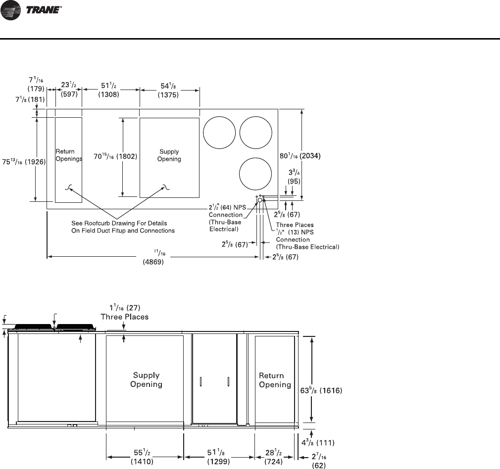
Figure 1. 60 Hz 27½-35, 50 Hz 23-29 Tons (TCD, TED,
YCD low heat)
Unit Dimensions and Weights
RT-SVX34H-EN 15
Notes:
•On horizontal units, the VFD is located between the
supply and return ductwork, which makes access
limited.
•For combination of horizontal and downflow openings
(digit 3 = F or R) see Figure 1, p. 14 for appropriate
downflow/upflow dimensions and Figure 2, p. 15 for
appropriate horizontal dimensions.
Note: Dimensions in ( ) are mm, 1”= 25.4 mm.
Figure 2. Rear view showing duct openings for horizontal supply and return, 60 Hz 27½-35, 50 Hz 23-29 Tons (TCH,
TEH, YCH low heat)
1 1/4
(32)
3 1/4
(81)
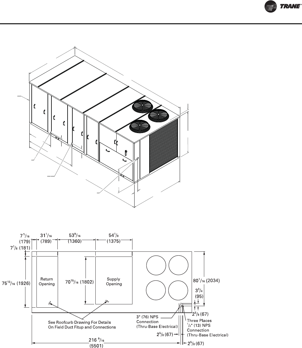
Figure 3. 60 Hz 27½-35, 50 Hz 23-29 Tons (TC, TE, YC low heat)
NOTES:
1. SEE DETAIL HOOD DRAWING FOR HORIZONTAL /
DOWNFLOW UNITS FOR ADDITIONAL DIMENSION
AND LOCATION.
179 3/4"
4565.65mm
42"
1066.8mm
83 13/16"
2128.8mm
90 1/16"
2287.5mm
180 5/16"
4579.9mm
90 3/8"
2295.5mm
5 3/8"
136.5mm
7 9/16"
192.1mm
3.25 [82.55mm] TO TOP OF FAN GRILLE
70 7/16"
1789.1mm
31.39"
797.3mm
6.91"
175.6mm
1 1/4" [31.7mm]
FEMALE
PVC PIPE
3/4" [19.0mm] NPT
GAS INLET
SEE NOTE 2
CUSTOMER
CONNECTION POINT
Unit Dimensions and Weights
16 RT-SVX34H-EN
Notes:
•On horizontal units, the VFD is located between the
supply and return ductwork, which makes access
limited.
•For combination of horizontal and downflow openings
(digit 3 = F or R) see Figure 4, p. 16 for appropriate
downflow/upflow dimensions and Figure 5, p. 16 for
appropriate horizontal dimensions.
Figure 4. 60 Hz 27½-35, 50 Hz 23-29 Tons (YD high heat)
191
Figure 5. Duct openings, 60 Hz 27½-35, 50 Hz 23-29 Tons (YH high heat)
1 1/4
(32)
3 1/4
(81)
Unit Dimensions and Weights
RT-SVX34H-EN 17
Note: Dimensions in ( ) are mm, 1”= 25.4 mm.
Figure 6. 60 Hz 27½-35, 50 Hz 23-29 Tons (YC high heat)
5270.5mm
207 1/2"
42"
5 3/8"
83 13/16"
2128.8mm
7 9/16"
208 1/16"
5284.7mm
90 5/8"
2301.8mm
90 1/16"
70 7/16"
31.39"
6.89"
PVC PIPE FEMALE
1" [25.4MM] NPT
GAS INLET
NOTES:
1. SEE ROOFCURB DRAWING FOR DETAILS
ON FIELD DUCT FITUP AND CONNECTIONS
2. SEE DETAIL HOOD DRAWING FOR HORIZONTAL /
DOWNFLOW UNITS FOR ADDITIONAL DIMENSION
AND LOCATION.
SEE NOTE 2
CUSTOMER
CONNECTION POINT
1066.8mm
2287.5mm
136.5m
192.1m
3.25 [82.55mm] TO
TOP OF FAN GRILLE
1789.1mm
797.3mm
175mm
1 1/4" [31.7mm]
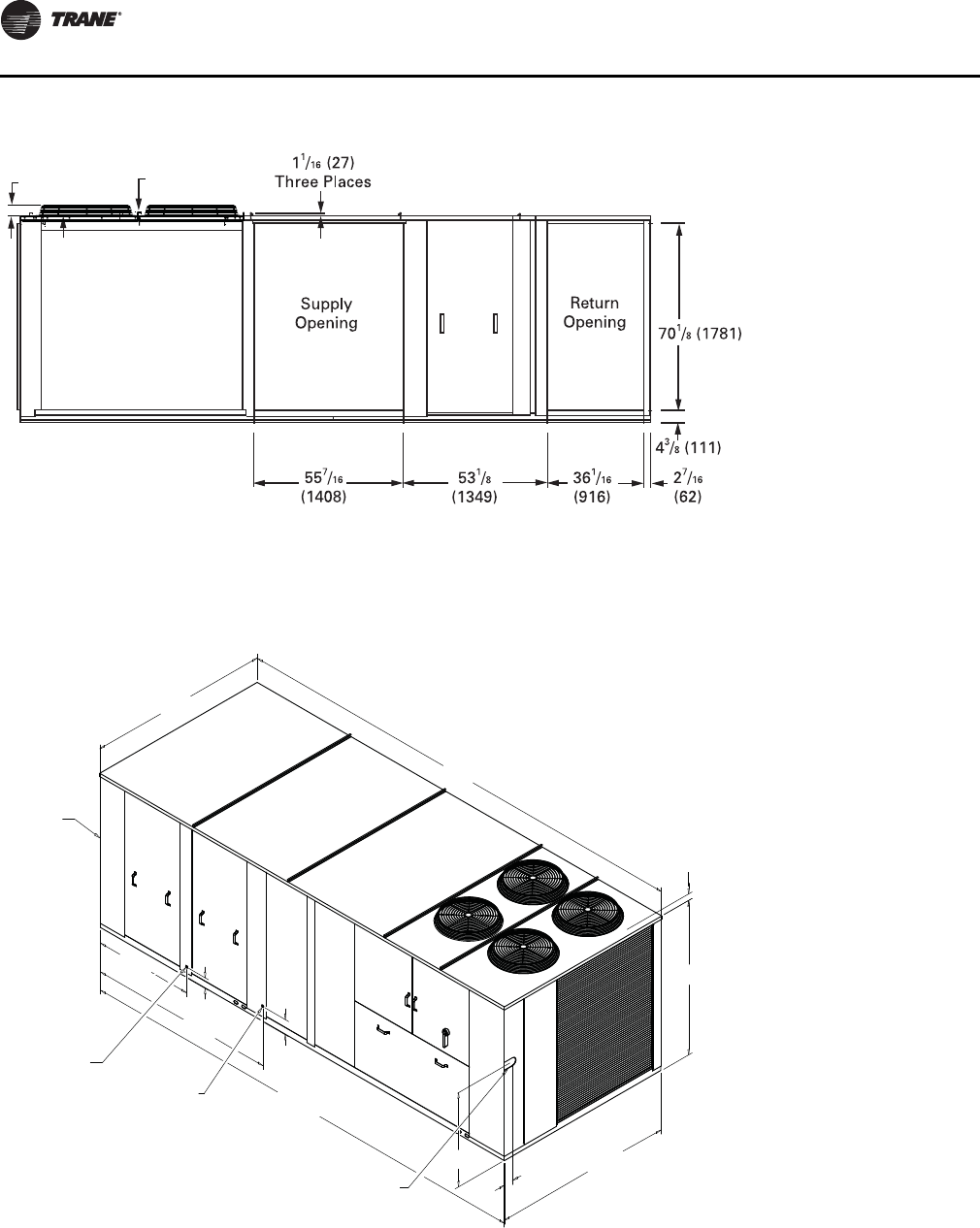
Figure 7. 60 Hz 40-50, 50 Hz 33-42 Tons (TD, TD, YD low and high heat)
Unit Dimensions and Weights
18 RT-SVX34H-EN
Notes:
•On horizontal units, the VFD is located between the
supply and return ductwork, which makes access
limited.
•For combination of horizontal and downflow openings
(digit 3 = F or R) see Figure 7, p. 17 for appropriate
downflow/upflow dimensions and Figure 8, p. 18 for
appropriate horizontal dimensions.
Note: Dimensions in ( ) are mm, 1”= 25.4 mm.
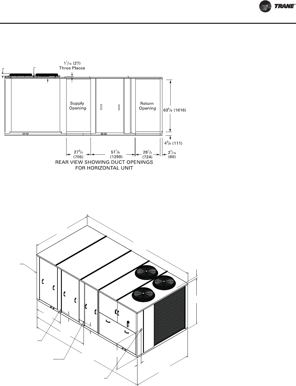
Figure 8. Duct openings, 60 Hz 40-50, 50 Hz 33-42 Tons (TH, TH, YH low and high heat)
1 1/4
(32)
3 1/4
(81)
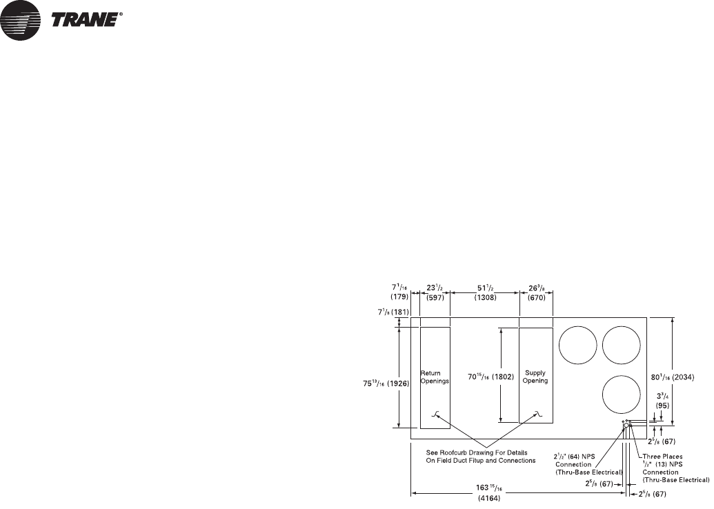
Figure 9. 60 Hz 40-50, 50 Hz 33-42 Tons (TC, TE, YC low and high heat)
7 9/16"
232 3/8"
5902.3mm
232 3/4"
5911.8mm
90 5/8"
49 9/16"
1258.8mm
93 3/8"
2371.7mm
5 5/16"
90 1/16"
77"
1955.8mm
32.84"
834.2mm
4.66"
118.4mm
NOTES:
1. SEE ROOFCURB DRAWING FOR DETAILS
ON FIELD DUCT FITUP AND CONNECTIONS
2. SEE DETAIL HOOD DRAWING FOR HORIZONTAL /
DOWNFLOW UNITS FOR ADDITIONAL DIMENSION
AND LOCATION.
SEE NOTE 2
CUSTOMER
CONNECTION POINT
2301.8mm
PVC PIPE FEMALE
1" [25.4MM] NPT
HIGH HEAT GAS INLET
2287.5mm
136.5m
192.1m
3.25 [82.55mm] TO
TOP OF FAN GRILLE
1 1/4" [31.7mm]
3/4" [19MM] NPT
LOW HEAT GAS INLET
Unit Dimensions and Weights
RT-SVX34H-EN 19
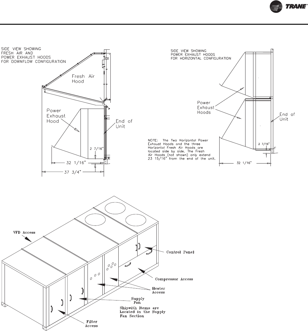
Figure 10. Fresh air and power exhaust dimensions for TC*, TE*, and YC* units
Figure 11. Location of “Ship With” items for TC*, TE*, and YC* units
Unit Dimensions and Weights
20 RT-SVX34H-EN
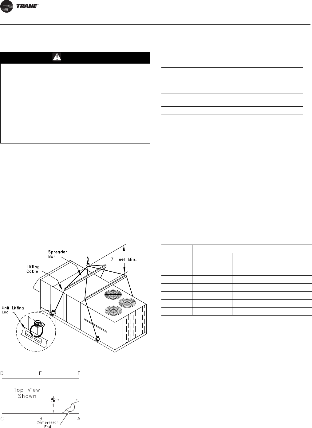
Unit Rigging and Placement
Use spreader bars as shown in the diagram. Refer to the
Installation manual or nameplate for unit weight. Refer to
the Installation instructions located inside the control
panel for further rigging information.
1. Verify that the roof curb has the proper gaskets
installed and is level and square to assure an adequate
curb-to-unit seal.
The units must be as level as possible in order to
assure proper condensate flow out of the unit. The
maximum side-to-side and end-to-end slope allowable
in any application is listed in Table 2, p. 20.
WARNING
Heavy Objects!
Ensure that all the lifting equipment used is properly
rated for the weight of the unit being lifted. Each of the
cables (chains or slings), hooks, and shackles used to
lift the unit must be capable of supporting the entire
weight of the unit. Lifting cables (chains or slings) may
not be of the same length. Adjust as necessary for even
unit lift. Other lifting arrangements could cause
equipment or property damage. Failure to follow
instructions above or properly lift unit could result in
unit dropping and possibly crushing operator/
technician which could result in death or serious injury.
Figure 12. Unit rigging
Figure 13. Center of gravity
X
Y
Z (see note 2)
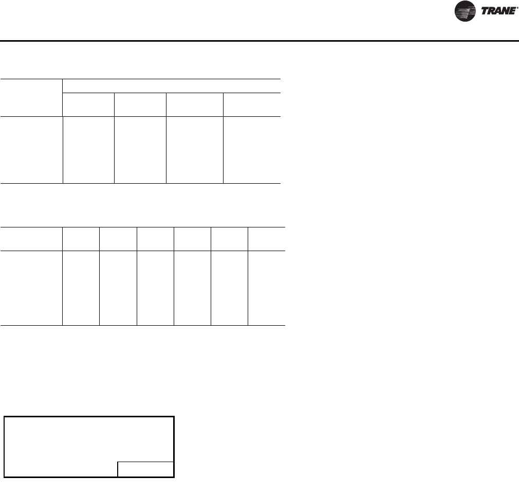
Table 1. Minimum operating clearances installation
(horizontal, downflow, and mixed airflow
configurations)
Recommended Clearances
Single Unit Economizer/
Exhaust End
Condenser
Coil(a)
Orientation
End/Side
(a) Condenser coil is located at the end and side of the unit.
Service Side
Access
TC*, TE*, YC*
27.5 to 50 Tons 6 Feet 8 Feet 4 Feet
Distance Between Units
Multiple Unit Economizer/
Exhaust End End/Side Service Side
Access
TC*, TE*, YC*
27.5 to 50 Tons 12 Feet 16 Feet 8 Feet
Table 2. Maximum slope
Cabinet End to End
(inches) Side to Side
(inches)
“A” (27.5 - 35 Ton Low Heat) 3 1/2 1 5/8
“B” (27.5 - 35 Ton High Heat) 4 1 5/8
“C” (All 40 and 50 Ton Units) 4 1/2 1 5/8
Note: Do not exceed these allowances. Correct the improper slope by
building up the curb base. The material used to raise the base must
be adequate to support both the curb and the unit weight.
Table 3. Center of gravity
Unit Model
Center-of-Gravity (inches)
YC Low Heat
Dimension YC High Heat
Dimension TC/TE
Dimension
XY ZXY ZXY Z
***330/275* 41 76 33 41 84 33 42 76 33
***360/305* 43 77 33 43 85 33 44 77 33
***420/350* 42 78 33 42 86 33 43 78 33
***480/400* 42 111 35 42 111 35 42 111 35
***600/500* 43 108 35 43 108 35 43 108 35
Note: Center-of-gravity dimensions are approximate, and are based on the
unit equipped with: standard efficiency coils, standard efficiency
motors, economizer, and throwaway filters.
Note: Z dimension is upward from the base of the unit.
Example:
Locating the center-of-gravity for a YC-360 MBH High Heat unit with 100%
exhaust.
X = 43 inches inward from the control panel side
Y = 85 inches inward from the compressor end
Z = 33 inches upward from the base
Unit Dimensions and Weights
RT-SVX34H-EN 21
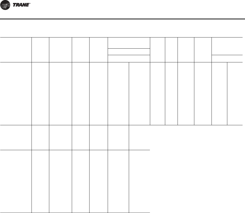
Table 4. Approximate units operating weights — lbs./kg1
Unit Models
(60Hz/50Hz)
Basic Unit Weights1
YC
Low Heat YC
High Heat TC TE
330/275 3720 / 1687 4150 / 1882 3590 / 1628 3610 / 1637.5
360/305 3795 / 1721 4225 / 1916 3665 / 1662 3685 / 1671.5
420/350 3876 / 1758 4306 / 1953 3746 / 1699 3766 / 1708
480/400 4825 / 2189 4950 / 2245 4565 / 2071 4600 / 2086.5
600/500 5077 / 2303 5202 / 2360 4827 / 2189.5 4852 / 2201
1. Basic unit weight includes minimum horsepower supply fan motor.
Table 5. Point loading average weight1,2 — lbs./kg
Unit Models
(60Hz/50Hz) A B C D E F
330/275 852 / 386 695 / 315 754 / 342 740 / 335 602 / 273 504 / 228
360/305 878 / 398 681 / 309 750 / 340 713 / 323 577 / 262 622 / 282
420/350 841 / 381 842 / 382 669 / 303 735 / 333 582 / 264 634 / 287
480/400 835 / 378 869 / 394 950 / 431 748 / 339 769 / 349 776 / 352
600/500 882 / 400 931 / 422 954 / 433 740 / 336 844 / 382 847 / 384
Notes:
1. Point loading is identified with corner A being the corner with the compressors.
As you move clockwise around the unit as viewed from the top, mid-point B,
corner C, corner D, mid-point E and corner F.
2. Point load calculations provided are based on the unit weight for YC high heat
gas models.
DE F
TOP VIEW
OF UNIT
COMPRS
CBA
Unit Dimensions and Weights
22 RT-SVX34H-EN
Table 6. Approximate operating weights— optional components — lbs./kg
Unit Model
(60Hz/50Hz) Baro.
Relief Power
Exhaust
0-25%
Man
Damper Econ.
Var. Freq. Drives
(VFD’s)
Serv
Valves
Thru-
the
base
Elec.
Non-
Fused
Discon.
Switch
Factory
GFI
with
Discon.
Switch
Roof CurbW/O With
Bypass Lo Hi
**(D,F)330/275 110/50 165/74 50/23 260/117 85/39 115/52 18/8 6/3 30/14 85/38 310/141 330/150
**(H,R)330/275 145/65 200/90 50/23 285/128 85/39 115/52 18/8 6/3 30/14 85/38 310/141 330/150
**(D,F)360/305 110/50 165/74 50/23 260/117 85/39 115/52 18/8 6/3 30/14 85/38 310/141 330/150
**(H,R)360/305 145/65 200/90 50/23 285/128 85/39 115/52 18/8 6/3 30/14 85/38 310/141 330/150
**(D,F)420/350 110/50 165/74 50/23 260/117 85/39 115/52 18/8 6/3 30/14 85/38 310/141 330/150
**(H,R)420/350 145/65 200/90 50/23 285/128 85/39 115/52 18/8 6/3 30/14 85/38 310/141 330/150
**(D,F)480/400 110/50 165/74 50/23 290/131 115/52 150/68 18/8 6/3 30/14 85/38 365/169 365/169
**(H,R)480/400 145/65 200/90 50/23 300/135 115/52 150/68 18/8 6/3 30/14 85/38 365/169 365/169
**(D,F)600/500 110/50 165/74 50/23 290/131 115/52 150/68 18/8 6/3 30/14 85/38 365/169 365/169
**(H,R)600/500 145/65 200/90 50/23 300/135 115/52 150/68 18/8 6/3 30/14 85/38 365/169 365/169
Unit Model
(60Hz/50Hz) HGRH
Coil
Tool-Less
Condenser
Hail
Guards
Ultra
Low
Leak
Econ
Ultra
Low
Leak
50%
Exhaust
Ultra Low
Leak
100%
Exhaust
High
Efficiency
(eStage)
**(D,F)330/275 107/49 105/48 112/51 34 / 15 74 / 34 326/148
**(H,R)330/275 107/49 105/48 78/35 34 / 15 77 / 35 326/148
**(D,F)360/305 107/49 105/48 112/51 34 / 15 74 / 34 255/116
**(H,R)360/305 107/49 105/48 78 /35 34 / 15 77 / 35 255/116
**(D,F)420/350 107/49 105/48 112/51 34 / 15 74 / 34 173/78
**(H,R)420/350 107/49 105/48 78/35 34 / 15 77 / 35 173/78
**(D,F)480/400 112/51 130/59 114/52 34 / 15 74 / 34 241/109
**(H,R)480/400 112/51 130/59 100/45 34 / 15 84 / 38 241/109
**(D,F)600/500 112/51 130/59 114/52 34 / 15 74 / 34 -25/-11
**(H,R)600/500 112/51 130/59 100/45 34 / 15 84 / 38 -25/-11
Note: Basic unit weight includes minimum horsepower supply fan motor.
RT-SVX34H-EN 23
Installation General Requirements
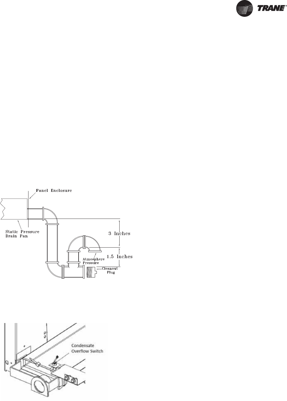
Condensate Drain Connection
Each commercial rooftop unit is equipped with one (1) 1-
1/4 inch Female PVC condensate drain connection.
Refer to Figure 11, p. 19 for the location of the connector. A
condensate trap must be installed due to the drain
connection being on the “negative pressure” side of the
fan. Install a P-Trap at the unit using the guidelines in
Figure 14, p. 23.
Pitch the drain line at least 1/2 inch for every 10 feet of
horizontal run to assure proper condensate flow.
Ensure that all condensate drain line installations comply
with applicable building and waste disposal codes.
Notes:
•For units with optional Condensate Overflow Switch
(COF), the switch will not work properly if unit is not
level or slightly sloped toward switch.
•To ensure proper condensate flow during operation
the unit and the curb must be level.
Condensate Overflow Switch
This switch protects building from condensate overflow
damage. It is factory-installed and tested.
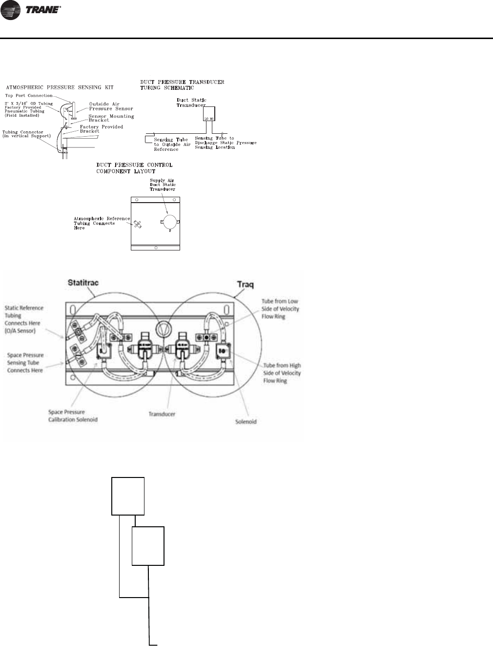
O/A Sensor & Tubing Installation
An Outside Air Pressure Sensor is shipped with all units
designed to operate on traditional variable air volume
applications (non-SZ VAV) and units with Statitrac™.
A duct pressure transducer and the outside air sensor is
used to control the discharge duct static pressure to within
a customer-specified controlband. Refer to the illustration
in Figure 16, p. 24 and the following steps to install the
sensor and the pneumatic tubing.
1. Remove the O/A pressure sensor kit located inside the
fan section. The kit contains the following items;
•an O/A static pressure sensor
•a sensor mounting bracket
•50’ of 3/16” O.D. pneumatic tubing
•mounting hardware
2. Using two #10-32 x 1-3/4” screws provided, install the
sensor's mounting bracket to the factory provided
bracket (near the fan section).
3. Using the #10-32 x 1/2” screws provided, install the O/
A static pressure sensor vertically to the sensor
bracket.
4. Remove the dust cap from the tubing connector
located below the sensor in the vertical support.
5. Attach one end of the 50' x 3/16” O.D. factory provided
pneumatic tubing to the sensor's top port, and the
other end of the tubing to the connector in the vertical
support. Discard any excess tubing.
Units with Statitrac™
1. Open the filter access door, and locate the Statitrac
Transducer Assembly illustrated in Figure 17, p. 24.
There are two tube connectors mounted on the left of
the solenoid and transducers. Connect one end of the
field provided 1/4” (length 50-100 ft.) or 3/8” (length
greater than 100 ft.) O.D. pneumatic tubing for the
space pressurization control to the fitting indicated in
the illustration.
2. Route the opposite end of the tubing to a suitable
location inside the building. This location should be
the largest open area that will not be affected by
sudden static pressure changes.
Figure 14. Condensate trap installation
Figure 15. Condensate overflow switch location
Installation General Requirements
24 RT-SVX34H-EN
Note: Statitrac and Traq transducer assembly shown.
Figure 16. Pressure tubing
Figure 17. Transducer assembly
LO HI
CNO
NC
Sensing Tube
to Traq LO Side
Pressure Port
Airow
Transducer
Sensing Tube
to Traq HI Side
Pressure Port
RT-SVX34H-EN 25
Installation Electrical
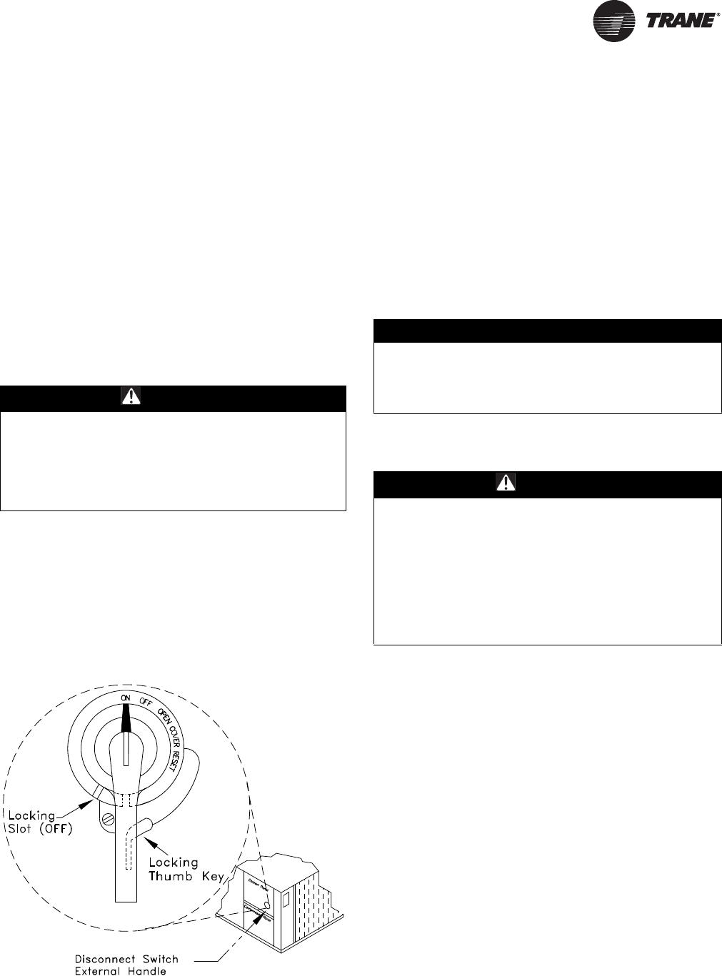
Disconnect Switch External
Handle (Factory Mounted Option)
Units ordered with the factory mounted disconnect switch
come equipped with an externally mounted handle. This
allows the operator to disconnect power from the unit
without having to open the control panel door. The handle
location and its three positions are shown below;
ON - Indicates that the disconnect switch is closed,
allowing the main power supply to be applied at the unit.
OFF - Indicates that the disconnect switch is open,
interrupting the main power supply at the unit.
OPEN COVER/RESET - Turning the handle to this position
releases the handle from the disconnect switch, allowing
the control panel door to be opened.
Once the door has been opened, it can be closed with the
handle in any one of the three positions outlined above,
provided it matches the disconnect switch position. The
handle can be locked in the “OFF” position. While holding
the handle in the “OFF” position, push the spring loaded
thumb key, attached to the handle, into the base slot. Place
the lock shackle between the handle and the thumb key.
This will prevent it from springing out of position.
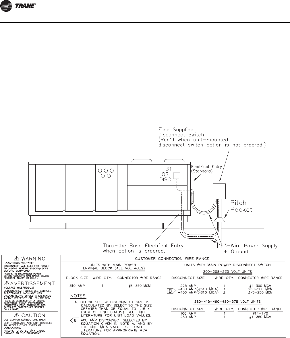
An overall layout of the field required power wiring is
illustrated in Figure 19, p. 26. To insure that the unit supply
power wiring is properly sized and installed, follow the
guidelines outlined below.
Note: All field installed wiring must conform to NEC
guidelines as well as State and Local codes.
Verify that the power supply available is compatible with
the unit's name plate ratings for all components. The
available power supply must be within 10% of the rated
voltage stamped on the nameplate. Use only copper
conductors to connect the 3-phase power supply to the
unit.
Main Power Wiring
1. Table 7, p. 27 to Table 12, p. 29 list the electrical service
sizing data. The electrical service must be protected
from over current and short circuit conditions in
accordance with NEC requirements. Protection
devices must be sized according to the electrical data
on the nameplate. Refer to “Electrical Wire Sizing and
Protection Device Equations” on page 29 for
determining:
a. The appropriate electrical service wire size based
on “Minimum Circuit Ampacity” (MCA),
b. The “Maximum Over current Protection” (MOP)
device.
c. The “Recommended Dual Element fuse size” (RDE).
2. If the unit is not equipped with an optional factory
installed Nonfused disconnect switch, a field supplied
disconnect switch must be installed at or near the unit
in accordance with the National Electrical Code (NEC
latest edition). Refer to DSS calculations “Electrical
Wire Sizing and Protection Device Equations” on
page 29 for determining correct size.
WARNING
Hazardous Voltage!
Disconnect all electric power, including remote
disconnects before servicing. Follow proper lockout/
tagout procedures to ensure the power can not be
inadvertently energized. Failure to disconnect power
before servicing could result in death or serious injury.
Figure 18. Disconnect switch
NOTICE:
Use Copper Conductors Only!
Unit terminals are not designed to accept other types of
conductors. Failure to use copper conductors could
result in equipment damage.
WARNING
Proper Field Wiring and Grounding
Required!
All field wiring MUST be performed by qualified
personnel. Improperly installed and grounded field
wiring poses FIRE and ELECTROCUTION hazards. To
avoid these hazards, you MUST follow requirements for
field wiring installation and grounding as described in
NEC and your local/state electrical codes. Failure to
follow code could result in death or serious injury.
Installation Electrical
26 RT-SVX34H-EN
Location for the electrical service entrance is shown in
the unit dimensional drawings beginning with
Figure 1, p. 14. Complete the unit's power wiring
connections onto either the main terminal block HTB1,
or the factory mounted nonfused disconnect switch
inside the unit control panel.
Note: When the factory installed through-the-base
option is not used, the installing contractor is
required to seal any holes made in the base of the
unit to prevent water from leaking into the building.
3. Provide proper grounding for the unit in accordance
with local and national codes.
Through-the-Base Electrical (Optional
Accessory)
Liquid-tight conduit couplings are secured to the base of
the unit for both power and control wiring. Liquid-tight
conduit must be field installed between the couplings and
the unit control box to prevent water leaks into the
building.
Note: If the unit is set on the roof curb and temporary
auxiliary heat is provided in the building, it is
recommended that the electrical and control wiring
conduit opening in the control box be temporarily
sealed to provide a vapor barrier.
Figure 19. Typical field power wiring
Installation Electrical
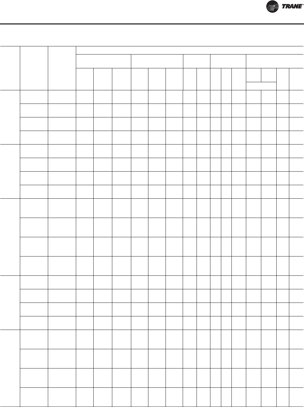
RT-SVX34H-EN 27
Table 7. 27½-50 ton electrical service sizing data—60Hz1
Fan Motors
Model
Electrical
Characteri
stics
Allowable
Voltage
Range
Compressor - Std
Efficiency Compressor - High
Efficiency, eStage Supply Condenser Exhaust
No/
Ton RLA
(Ea.) LRA
(Ea.) No/
Ton RLA
(Ea.) LRA
(Ea.) HP FLA No HP FLA
(Ea.)
50
%100
%
HP FLA
(Ea.)No.
TC/TE/
YC*330
208/60/3 187-229 1/12,
1/13 44.0/
50.5 304/
315 1/6,
2/9 28.0,
37.1 203,
267 7.5
10.0 22.2
29.5 31.17.0 1 2 1.04.1
230/60/3 207-253 1/12,
1/13 44.0/
50.5 304/
315 1/6,
2/9 28.0,
37.1 203,
267 7.5
10.0 18.8
25.2 31.17.0 1 2 1.04.1
460/60/3 414-506 1/12,
1/13 21.0/
23.0 147/
158 1/6,
2/9 14.1,
16.8 98, 142 7.5
10.0 9.4
12.6 31.13.5 1 2 1.01.8
575/60/3 517-633 1/12,
1/13 17.5/
19.0 122/
136 1/6,
2/9 12.2,
14.7 84, 103 7.5
10.0 7.8
10.1 31.12.8 1 2 1.01.4
TC/TE/
YC*360
208/60/3 187-229 2/13 50.5 315/
315 1/6,
2/10 28.0,
40.9 203,
267 7.5
10.0 22.2
29.5 31.17.0 1 2 1.04.1
230/60/3 207-253 2/13 50.5 315/
315 1/6,
2/10 28.0,
40.9 203,
267 7.5
10.0 18.8
25.2 31.17.0 1 2 1.04.1
460/60/3 414-506 2/13 23.0 158/
158 1/6,
2/10 14.1,
18.6 98, 142 7.5
10.0 9.4
12.6 31.13.5 1 2 1.01.8
575/60/3 517-633 2/13 19.0 136/
136 1/6,
2/10 12.2,
15.4 84, 103 7.5
10.0 7.8
10.1 31.12.8 1 2 1.01.4
TC/TE/
YC*420
208/60/3 187-229 1/13,
1/15 50.5/
56.0 315/
351 1/6,
2/11 28.0,
44.9 203,
304
7.5
10.0
15.0
22.2
29.5
40.7 31.17.0 1 2 1.04.1
230/60/3 207-253 1/13,
1/15 50.5/
56.0 315/
351 1/6,
2/11 28.0,
44.9 203,
304
7.5
10.0
15.0
18.8
25.2
35.4 31.17.0 1 2 1.04.1
460/60/3 414-506 1/13,
1/15 23.0/
27.5 158/
197 1/6,
2/11 14.1,
19.2 98,
147
7.5
10.0
15.0
9.4
12.6
17.7 31.13.5 1 2 1.01.8
575/60/3 517-633 1/13,
1/15 19.0/
23.0 136/
146 1/6,
2/11 12.2,
16.6 84,
122
7.5
10.0
15.0
7.8
10.1
15.1 31.12.8 1 2 1.01.4
TC/TE/
YC*480
208/60/3 187-229 1/13,
1/20 50.5/
83.9 315/
485 1/8,
2/13 31.1,
50.5 203,
315 10.0
15.0 29.5
40.7 41.17.0 1 2 1.55.4
230/60/3 207-253 1/13,
1/20 50.5/
83.9 315/
485 1/8,
2/13 31.1,
50.5 203,
315 10.0
15.0 25.2
35.4 41.17.0 1 2 1.55.4
460/60/3 414-506 1/13,
1/20 23.0/
34.0 158/
215 1/8,
2/13 14.1,
23.0 98,
158 10.0
15.0 12.6
17.7 41.13.5 1 2 1.52.7
575/60/3 517-633 1/13,
1/20 19.0/
27.3 136/
175 1/8,
2/13 11.5,
19.0 84,
136 10.0
15.0 10.1
15.1 41.12.8 1 2 1.52.2
TC/TE/
YC*600
208/60/3 187-229 2/13,
1/15 50.5/
56.0 315/
351 1/10,
2/15 40.9,
56.0 267,
345
10.0
15.0
20.0
29.5
40.7
56.1 41.17.0 1 2 1.55.4
230/60/3 207-253 2/13,
1/15 50.5/
56.0 315/
351 1/10,
2/15 40.9,
56.0 267,
345
10.0
15.0
20.0
25.2
35.4
49.4 41.17.0 1 2 1.55.4
460/60/3 414-506 2/13,
1/15 23.0/
27.5 158/
197 1/10,
2/15 18.6,
27.5 142,
155
10.0
15.0
20.0
12.6
17.7
24.7 41.13.5 1 2 1.52.7
575/60/3 517-633 2/13,
1/15 19.0/
23.0 136/
146 1/10,
2/15 15.4,
23.0 103,
126
10.0
15.0
20.0
10.1
15.1
19.6 41.12.8 1 2 1.52.2
Notes:
1. All customer wiring and devices must be installed in accordance with local and national electrical codes.
2. 100% Power Exhaust is with or without Statitrac™.
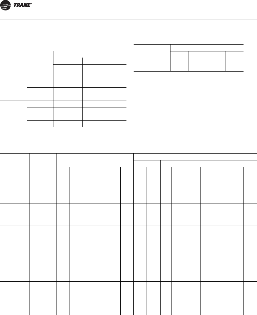
Installation Electrical
28 RT-SVX34H-EN
Table 8. Electrical service sizing data — electric heat
module (electric heat only) — 60 Hz
Models: TE(D,H,F,R) 330—600 Electric Heat FLA
KW Heater
Nominal
Unit Size
(Tons)
Nominal
Unit
Voltage
36 54 72 90 108
FLA FLA FLA FLA FLA
27½-35
208 74.9 112.4 — — —
230 86.6 129.9 — — —
460 43.3 65.0 86.6 108.3 —
575 — 52.0 69.3 86.6 —
40- 50
208 — 112.4 — — —
230 — 129.9 — — —
460 — 65.0 86.6 108.3 129.9
575 — 52.0 69.3 86.6 103.9
Note: All FLA in this table are based on heater operating at 208, 240, 480,
and 600 volts.
Table 9. Electrical service sizing data — crankcase
heaters (heating mode only) — 60Hz
Nominal
Unit Size (Tons)
FLA Add Unit Voltage
200 230 460 575
27½ - 35 1111
40, 50 2211
Table 10. Electrical service sizing data — 50Hz
Model
Electrical
Characteris
tics
Compressor - Std
Efficiency Compressor -
High Efficiency
Fan Motors
Supply Condenser1Exhaust
No/
Ton RLA
(Ea.) LRA
(Ea.) No/
Ton RLA
(Ea.) LRA
(Ea.) HP
(kW) FLA No. HP
(kW) FLA
(Ea.)
50% 100% HP
(kW) FLA
(Ea.)No.
TC/TE/YC*275 380-415/50/3 1/10,
1/11 21.0/
23.0 147/
158 1/6,
2/9 14.1,
16.8 98,
142 7.5
(5.6) 13.6/
14.1 30.75
(0.56) 4.4 1 2 0.75
(0.56) 1.7
10
(6.8) 16.0/
15.5
TC/TE/YC*305 380-415/50/3 2/11 23.0 158 1/6,
2/10 14.1,
18.6 98,
142 7.5
(5.6) 13.6/
14.1 30.75
(0.56) 4.4 1 2 0.75
(0.56) 1.7
10
(6.8) 16.0/
15.5
TC/TE/YC*350 380-415/50/3 1/11,
1/12 23.0/
27.5 158/
197 1/6,
2/11 14.1,
19.2 98,
147 7.5
(5.6) 13.6/
14.1 30.75
(0.56) 4.4 1 2 0.75
(0.56) 1.7
10
(6.8) 16.0/
15.5
15
(10.5) 24.0/
26.0
TC/TE/YC*400 380-415/50/3 1/11,
1/17 23.0/
34.0 158/
215 1/8,
2/13 14.1,
23.0 98,
158 10
(6.8) 16.0/
15.5 40.75
(0.56) 4.4 1 2 1.0
(0.75) 2.5
15
(10.5) 24.0/
26.0
TC/TE/YC*500 380-415/50/3 2/11,
1/12 23.0/
27.5 158/
197 1/10,
2/15 18.6,
27.5 142,
155 10
(6.8) 16.0/
15.5 40.75
(0.56) 4.4 1 2 1.0
(0.75) 2.5
15
(10.5) 24.0/
26.0
20
(12.8) 29.0/
28.0
Notes:
1. All condenser fan motors are single phase.
2. All customer wiring and devices must be installed in accordance with local and national electrical codes.
3. Allowable voltage range for the 380V unit is 342-418V, allowable voltage range for the 415V unit is 373-456.
4. 100% Power Exhaust is with or without Statitrac
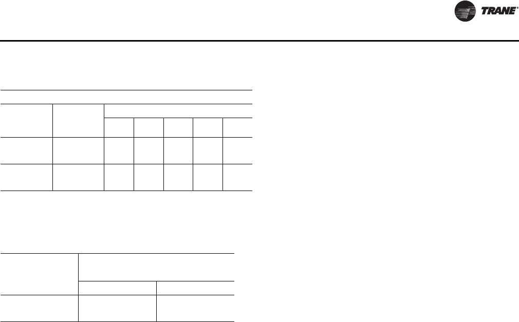
Installation Electrical
RT-SVX34H-EN 29
Electrical Wire Sizing and
Protection Device Equations
To correctly size the main power wiring based on MCA
(Minimum Circuit Ampacity), use the appropriate
equation listed below. Read the definitions that follow and
then use Calculation #1 for determining MCA (Minimum
Circuit Ampacity), MOP (Maximum Over current
Protection), and RDE (Recommended Dual Element fuse
size) for TC (Cooling Only) units and YC (Cooling with Gas
Heat) units. Use Calculation #2 for TE (Cooling with Electric
Heat) units.
Load Definitions:
• LOAD 1 = CURRENT OF THE LARGEST MOTOR
(Compressor or Fan Motor)
• LOAD 2 = SUM OF THE CURRENTS OF ALL
REMAINING MOTORS
• LOAD 3 = FLA (Full Load Amps) OF THE ELECTRIC
HEATER
• LOAD 4 = ANY OTHER LOAD RATED AT 1 AMP OR
MORE
• CRANKCASE HEATERS FOR HEATING MODE ONLY:
•208/230 VOLT
– 27.5 - 35 Ton Units, Add 1 Amp
– 40 - 50 Ton Units, Add 2 Amps
•460/575 VOLT
– 27.5 - 35 Tons Units, Add 1 Amp
– 40 - 50 Ton Units, Add 1 Amp
Calculation #1 - TC*, YC*-27.5 to 50 Ton Units
MCA = (1.25 x Load 1) + Load 2 + Load 4
MOP = (2.25 x Load 1) + Load 2 + Load 4 (See Note 1)
RDE = (1.5 x Load 1) + Load 2 + Load 4 (See Note 2)
Calculation # 2 - TE*-27.5 to 50 Ton Units
A. Single Source Power (all voltages)
To calculate the correct MCA (Minimum Circuit Ampacity),
MOP (Maximum Over current Protection), and RDE
(Recommended Dual Element fuse size), two (2) sets of
calculations must be performed;
1. Calculate the MCA, MOP and/or RDE values using the
above equation as if the unit is operating in the cooling
mode.
2. Calculate the MCA, MOP and/or RDE values as if the
unit is operating in the heating mode, as follows:
Note: When determining loads, the compressors and
condenser fan motors do not operate during the
heating cycle.
Units with less than 50 KW Heaters
MCA = 1.25 x (Load 1 + Load 2 + Load 4) + (1.25 x Load 3)
Units with 50 KW or Larger Heaters
MCA = 1.25 x (Load 1 + Load 2 + Load 4) + Load 3
The MCA value stamped on the nameplate is the largest of
the two calculated values.
MOP = (2.25 x Load 1) + Load 2 + Load 3 + Load 4 (See Note
1)
The MOP value stamped on the nameplate is the largest of
the two calculated values.
RDE = (1.5 x Load 1) + Load 2 + Load 3 + Load 4 (See Note 2)
Note: Select an over current protection device equal to
the MOP value. If the calculated MOP value does
not equal a standard size protection device listed in
NEC 240-6, select the next lower over current
protection device. If the calculated MOP value is
less than the MCA value, select the lowest over
current protection device which is equal to or larger
than the MCA, providing the selected over current
device does not exceed 800 amps.
Note: Select a Dual Element Fuse equal to the RDE value.
If the calculated RDE value does not equal a
standard dual element fuse size listed in NEC 240-
6, select the next higher fuse size. If the calculated
RDE value is greater than the MOP value, select a
Dual Element fuse equal to the calculated MOP
(Maximum Over current Protection) value
Table 11. Electrical service sizing data – electric heat
module (electric heat units only)—50Hz
Models: TE(D,H,F,R) 275 through 500 Electric Heat FLA
Nominal
Unit Size
(Tons)
Nominal
Unit
Voltage
KW Heater (380/415V)
23/27 34/40 45/54 56/67 68/81
23-29 380 34.5 51.1 68.9 85.5 –
415 37.6 55.6 – – –
33, 42 380 – 51.1 68.9 85.5 103.4
415 – 55.6 75.1 93.2 112.7
Note: All FLA in this table are based on heater operating at 380 or 415 volts
as shown above.
Table 12. Electrical service sizing data — crankcase
heaters (heating mode only) — 50Hz
Nominal Unit Size
(Tons)
FLA Add
Unit Voltage
380 415
23 - 29 1 1
33 - 42 1 1
Installation Electrical
30 RT-SVX34H-EN
Disconnect Switch Sizing (DSS)
Calculation A. - YC*, TC*, and TE* Units:
DSS = 1.15 X (LOAD1 + LOAD2 + LOAD4)
For TE* units, use calculations A and B.
Calculation B. - TE* Units:
DSS = 1.15 X (LOAD3 + Supply Fan FLA + Exhaust
Fan FLA).
Use the larger value of calculations A or B to size the
electrical disconnect switch.
Low Voltage Wiring
An overall layout of the various control options available
for a Constant Volume application is illustrated in
Figure 20, p. 32 and Figure 21, p. 33 illustrates the various
control options for a Variable Air Volume application. The
required number of conductors for each control device are
listed in the illustration.
A typical field connection diagram for the sensors and
other options are shown in the following section “Remote
Panels and Sensors”. These diagrams are representative of
standard applications and are provided for general
reference only. Always refer to the wiring diagram that
shipped with the unit for specific electrical schematic and
connection information.
Note: All field wiring must conform to NEC guidelines as
well as state and local codes.
Control Power Transformer
The 24 volt control power transformers are equipped with
internal circuit breakers. They are to be used only with the
accessories called out in this manual. If a circuit breaker
trips, be sure to turn off all power to the unit before
attempting to reset it.
On units equipped with the VFD option, an additional
control power transformer is used. The secondary is
protected with fuses. Should the fuse blow, be sure to turn
off all power to the unit before attempting to replace it.
Field Installed AC Control Wiring
Before installing any connecting wiring, refer to Table 13,
p. 30 for conductor sizing guidelines and;
•Use copper conductors unless otherwise specified.
•Ensure that the AC control voltage wiring between
the controls and the unit's termination point does
not exceed three (3) ohms/conductor for the length
of the run.
Note: Resistance in excess of 3 ohms per conductor may
cause component failure due to insufficient AC
voltage supply.
•Refer to dimensional information beginning with
Figure 1, p. 14 for the electrical access locations
provided on the unit.
•Do not run the AC low voltage wiring in the same
conduit with the high voltage power supply wiring.
Be sure to check all loads and conductors for grounds,
shorts, and miswiring. After correcting any discrepancies,
reset the circuit breakers by pressing the black button
located on the left side of the transformer.
WARNING
Hazardous Voltage!
Disconnect all electric power, including remote
disconnects before servicing. Follow proper lockout/
tagout procedures to ensure the power can not be
inadvertently energized. Failure to disconnect power
before servicing could result in death or serious injury.
WARNING
Proper Field Wiring and Grounding
Required!
All field wiring MUST be performed by qualified
personnel. Improperly installed and grounded field
wiring poses FIRE and ELECTROCUTION hazards. To
avoid these hazards, you MUST follow requirements for
field wiring installation and grounding as described in
NEC and your local/state electrical codes. Failure to
follow code could result in death or serious injury.
NOTICE:
Use Copper Conductors Only!
Unit terminals are not designed to accept other types of
conductors. Failure to use copper conductors could
result in equipment damage.
Table 13. AC conductors
Distance from unit to control Recommended wire size
000-460 feet 18 gauge
461-732 feet 16 gauge
733-1000 feet 14 gauge
Installation Electrical
RT-SVX34H-EN 31
Field Installed DC Control Wiring
Before installing the connecting wiring between the
components utilizing a DC analog output/input signal and
the unit, refer to Table 14, p. 31 for conductor sizing
guidelines and;
•Use standard copper conductor thermostat wire
unless otherwise specified.
•Ensure that the wiring between the controls and the
unit's termination point does not exceed two and a
half (2-1/2) ohms/conductor for the length of the
run.
Note: Resistance in excess of 21/2 ohms per conductor
can cause deviations in the accuracy of the
controls.
•Refer to dimensional drawings beginning with
Figure 1, p. 14 for the electrical access locations
provided on the unit.
•Do not run the electrical wires transporting DC
signals in or around conduit housing high voltage
wires.
Units equipped with the Trane Communication Interface
(TCI) option, which utilizes a serial communication link;
•Must be 18 AWG shielded twisted pair cable Belden
8760 or equivalent).
•Must not exceed 5,000 feet maximum for each link.
•Must not pass between buildings.
WARNING
Proper Field Wiring and Grounding
Required!
All field wiring MUST be performed by qualified
personnel. Improperly installed and grounded field
wiring poses FIRE and ELECTROCUTION hazards. To
avoid these hazards, you MUST follow requirements for
field wiring installation and grounding as described in
NEC and your local/state electrical codes. Failure to
follow code could result in death or serious injury.
NOTICE:
Use Copper Conductors Only!
Unit terminals are not designed to accept other types
of conductors. Failure to use copper conductors could
result in equipment damage.
Table 14. DC conductors
Distance from unit to control Recommended wire size
000-150 feet 22 gauge
151-240 feet 20 gauge
241-385 feet 18 gauge
386-610 feet 16 gauge
611-970 feet 14 gauge
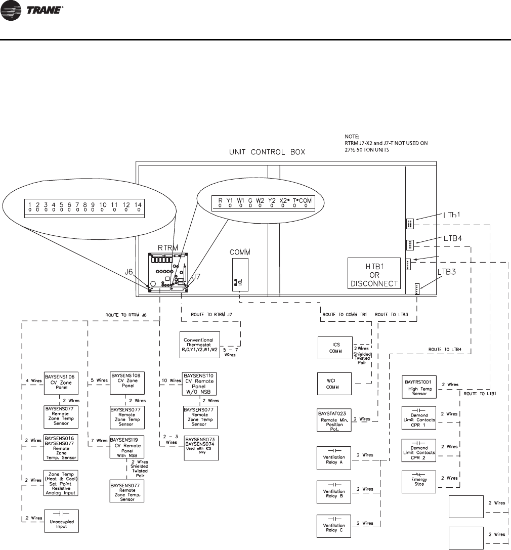
Installation Electrical
32 RT-SVX34H-EN
Figure 20. Typical field wiring requirements for CV and SZ VAV control options
LTB6
Space
Humidity
Sensor
Space
Humidistat
RTRM J7 Thermostat Inputs N/A for SZ VAV
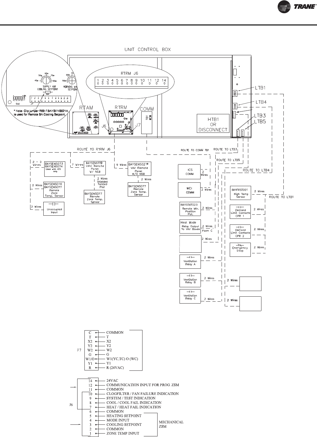
Installation Electrical
RT-SVX34H-EN 33
Figure 21. Typical field wiring requirements for traditional VAV control options
Customer
Changeover for
VAV Htg (MOD
GAS ONLY
*VAV Mode input: RTRM J6-2 to RTRM J6-4
If the unit does not have a Mode (Off, Auto) input from another source,
the following default applies: Short from J6-2 to J6-4 = AUTO mode,
Open from J6-2 to J6-4 = OFF mode.
LTB6
Space
Humidity
Sensor
Space
Humidistat
Figure 22. RTRM zone sensor/thermostat connections
PROGRAMMABLE
ZSM INPUTS
CV/SZ VAV/VAV
CONVENTIONAL
THERMOSTAT (CV ONLY)
MECHANICAL
ZSM INPUTS
CONVENTIONAL
THERMOSTAT
INPUTS
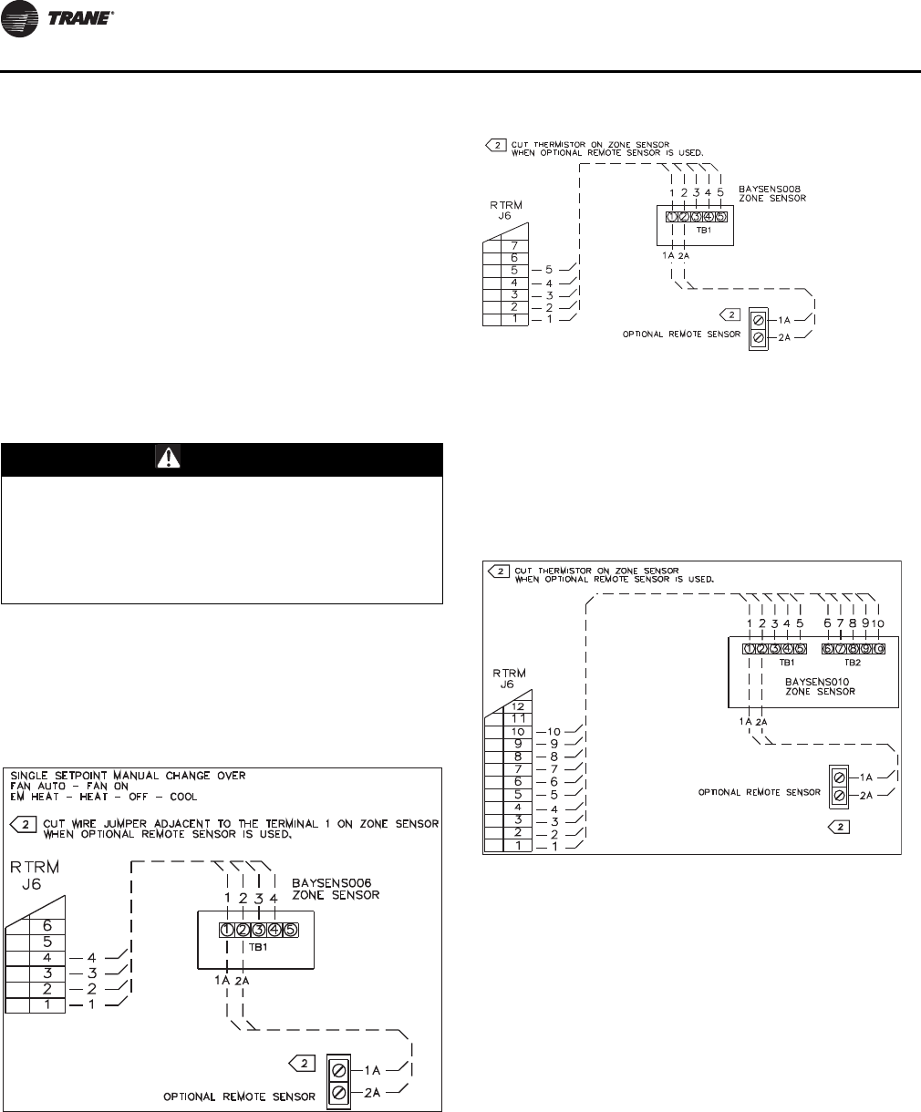
Installation Electrical
34 RT-SVX34H-EN
Remote Panels and Sensors
Constant Volume and Single Zone VAV
Control Options
The RTRM must have a zone sensor or conventional
thermostat (CV only) to operate the rooftop unit. If using a
zone sensor, mode capability depends upon the type of
sensor and/or remote panel selected to interface with the
RTRM. The possibilities are: Fan selection ON or AUTO,
System selection HEAT, COOL, AUTO, and OFF. Refer to
Figure 22, p. 33 for conventional thermostat connections
on Constant Volume units.
The following controls are available from the factory for
field installation on Constant Volume or Single Zone VAV
units.
Zone Panel (BAYSENS106*)
This electronic sensor features three system switch
settings (Heat, Cool, and Off) and two fan settings (On and
Auto). It is a manual changeover control with single
setpoint capability.
Zone Panel (BAYSENS108*)
This electronic sensor features four system switch settings
(Heat, Cool, Auto, and Off) and two fan settings (On and
Auto). It is a manual or auto changeover control with dual
setpoint capability. It can be used with a remote zone
temperature sensor BAYSENS077*.
Remote Panel W/O NSB (BAYSENS110*)
This electronic sensor features four system switch settings
(Heat, Cool, Auto, and Off) and two fan settings (On and
Auto) with four system status LED's. It is a manual or auto
changeover control with dual setpoint capability. It can be
used with a remote zone temperature sensor
BAYSENS077*.
Variable Air Volume (non-SZ VAV) Control
Options
The RTRM must have a mode input in order to operate the
rooftop unit. The normal mode selection used with a
remote panel with or without night setback, or ICS is AUTO
and OFF. Table 15, p. 35 lists the operating sequence
should a CV/SZ VAV zone sensor be applied to a traditional
VAV system having selectable modes; i.e. Fan selection
ON or AUTO. System selection HEAT, COOL, AUTO, and
OFF.
Default Mode Input for Discharge Air Control
For unit stand-alone operation without a remote panel or
an ICS connected, jumper between terminals J6-2 and J6-
4 on RTRM.
VHR Relay Output
For stand alone VAV unit operation, the VHR output should
be wired to drive VAV boxes to maximum position during
WARNING
Hazardous Voltage!
Disconnect all electric power, including remote
disconnects before servicing. Follow proper lockout/
tagout procedures to ensure the power can not be
inadvertently energized. Failure to disconnect power
before servicing could result in death or serious injury.
Figure 23. Zone panel (BAYSENS106*)
Figure 24. Zone panel (BAYSENS108*)
Figure 25. Remote panel W/O NSB (BAYSENS110*)
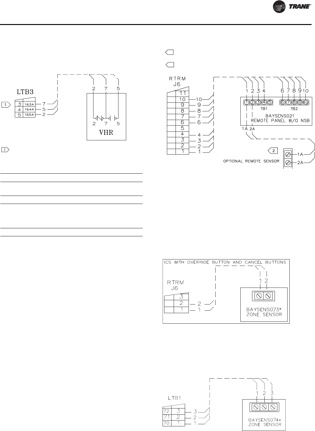
Installation Electrical
RT-SVX34H-EN 35
all heating modes and unoccupied periods. The VHR
contacts are shown in the de-energized position and will
switch (energize) during the above mentioned operating
modes.
The following Variable Air Volume controls are
available from the factory for field installation
Remote Zone Sensor (BAYSENS016*)
This bullet type temperature sensor can be used for;
outside air (ambient) sensing, return air temperature
sensing, supply air temperature sensing, remote
temperature sensing (uncovered), and for VAV zone reset.
Wiring procedures vary according to the particular
application and equipment involved. Refer to the unit
wiring diagrams, engineering bulletins, and/or any
specific instructions for connections. See Table 10 for the
Temp vs Resistance coefficient.
Remote Panel W/O NSB (BAYSENS021*)
This electronic sensor features two system switch settings
(Auto and Off), four system status LED's with single
setpoint capability. It can be used with a remote zone
temperature sensor BAYSENS077*.
The following Constant Volume or Variable Air
Volume (Traditional or Single Zone) controls
are available from the factory for field
installation.
Remote Zone Sensor (BAYSENS073*)
This electronic sensor features remote zone sensing and
timed override with override cancellation. It is used with a
Trane Integrated ComfortTM building management
system.
Remote Zone Sensor (BAYSENS074*)
This electronic sensor features single setpoint capability
and timed override with override cancellation. It is used
with a Trane Integrated ComfortTM building management
system.
Figure 26. VHR relay output
Table 15. Variable air volume mode operation
System Mode Fan “Auto” Fan “On”
Heat DWU Active
DWU Off DWU2
Off4DWU2
VAV Heating4
Cool VAV Cooling1VAV Cooling1
Auto DWU Active
DWU Off
DWU or
Cooling1,2,3,4
VAV Cooling1
DWU or
Cooling1,2,3,4
VAV Cooling or
Heating1
Off Off4 Off4
Notes:
1. If Cooling is selected the supply fan will run continuously. If VAV
Heating is activated the supply fan will run continuously.
2. If Daytime Warmup is Activated, the supply fan will run
continuously.
3. Auto changeover between Cooling and Daytime
Warmup depends upon the DWU initiate setpoint.
4. The fan will be Off any time the system selection switch
is “Off”.
Heat mode/unoccupied mode relay output to VAV
Note:
Figure 27. Remote panel W/O NSB (BAYSENS021*)
Figure 28. Remote zone sensor (BAYSENS073*)
Figure 29. Remote zone sensor (BAYSENS074*)
CUT RESISTOR R69 LOCATED ON RTAM NEAR SUPPLY AIR COOLING
SETPOINT POTENTIOMETER WHEN OPTIONAL REMOTE PANEL IS USED.
CUT WIRE JUMPER ADJACENT TO THE TERMINAL 1 ON ZONE SENSOR
WHEN OPTIONAL REMOTE SENSOR IS USED.
1
2
*
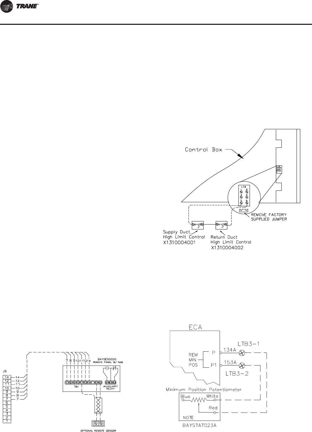
Installation Electrical
36 RT-SVX34H-EN
Remote Zone Sensor (BAYSENS077*)
This electronic sensor can be used with BAYSENS106*,
108*, 110*, 119*, or 021* Remote Panels. When this sensor
is wired to a BAYSENS119* Remote Panel, wiring must be
18 AWG Shielded Twisted Pair (Belden 8760 or equivalent).
Refer to the specific Remote Panel for wiring details.
Remote Panel with NSB (BAYSENS119*)
This 7 day programmable sensor features four periods for
Occupied/Unoccupied programming per day. Either one
or all four periods can be programmed. If the power is
interrupted, the program is retained in permanent
memory. If power is off longer than 2 hours, only the clock
and day may have to be reset.
The front panel allows selection of Occupied/Unoccupied
periods with two temperature inputs (Cooling Supply Air
Temperature and Heating Warm-up temperature) per
occupied period. The occupied supply air cooling setpoint
ranges between 40º and 80º Fahrenheit. The warm-up
setpoint ranges between 50º and 90º Fahrenheit with a 2
degrees deadband. The Unoccupied cooling setpoint
ranges between 45º and 98º Fahrenheit. The unoccupied
heating setpoint ranges between 43º and 96º Fahrenheit.
Note: In modulating gas heat units, the supply air heating
setpoint is the active setpoint with a BAYSENS119*
and must be set for the heater to function properly.
The modulating furnace will not react to the
Discharge Heating Setpoint on the NSB.
The liquid crystal display (LCD) displays zone temperature,
temperature setpoints, week day, time, and operational
mode symbols.
The options menu is used to enable or disable these
applicable functions:
Morning warm-up, economizer minimum position
override during unoccupied status, heat installed, remote
zone temperature sensor, 12/24 hour time display, and
daytime warm-up. See Table 16, p. 37 for the Temp vs
Resistance coefficient if an optional remote sensor is used.
During an occupied period, an auxiliary relay rated for 1.25
amps @ 30 volts AC with one set of single pole double
throw contacts is activated.
High Temperature Sensor (BAYFRST003*)
Provides high limit “shutdown” of the unit.
The sensor is used to detect high temperatures due to fire
in the air conditioning or ventilation ducts. The sensor is
designed to mount directly to the sheet metal duct. Each kit
contains two sensors. The return air duct sensor
(X1310004001) is set to open at 135 degrees F. The supply
air duct sensor (X1310004002) is set to open at 240
degrees F. The control can be reset after the temperature
has been lowered approximately 25 degrees F below the
cutout setpoint.
Remote Minimum Position Potentiometer
(BAYSTAT023*)
This device can be used with units with an economizer. It
allows the operator to remotely set the position of the
economizer dampers from 0% to 50% of fresh air entering
the space.
Figure 30. Remote sensor with night setback
BAYSENS119
Twisted/Shielded
Run Shield to
terminal 11
RTRM
Figure 31. High temperature sensor (BAYFRST003*)
Figure 32. Remote minimum position potentiometer
(BAYSTAT023)
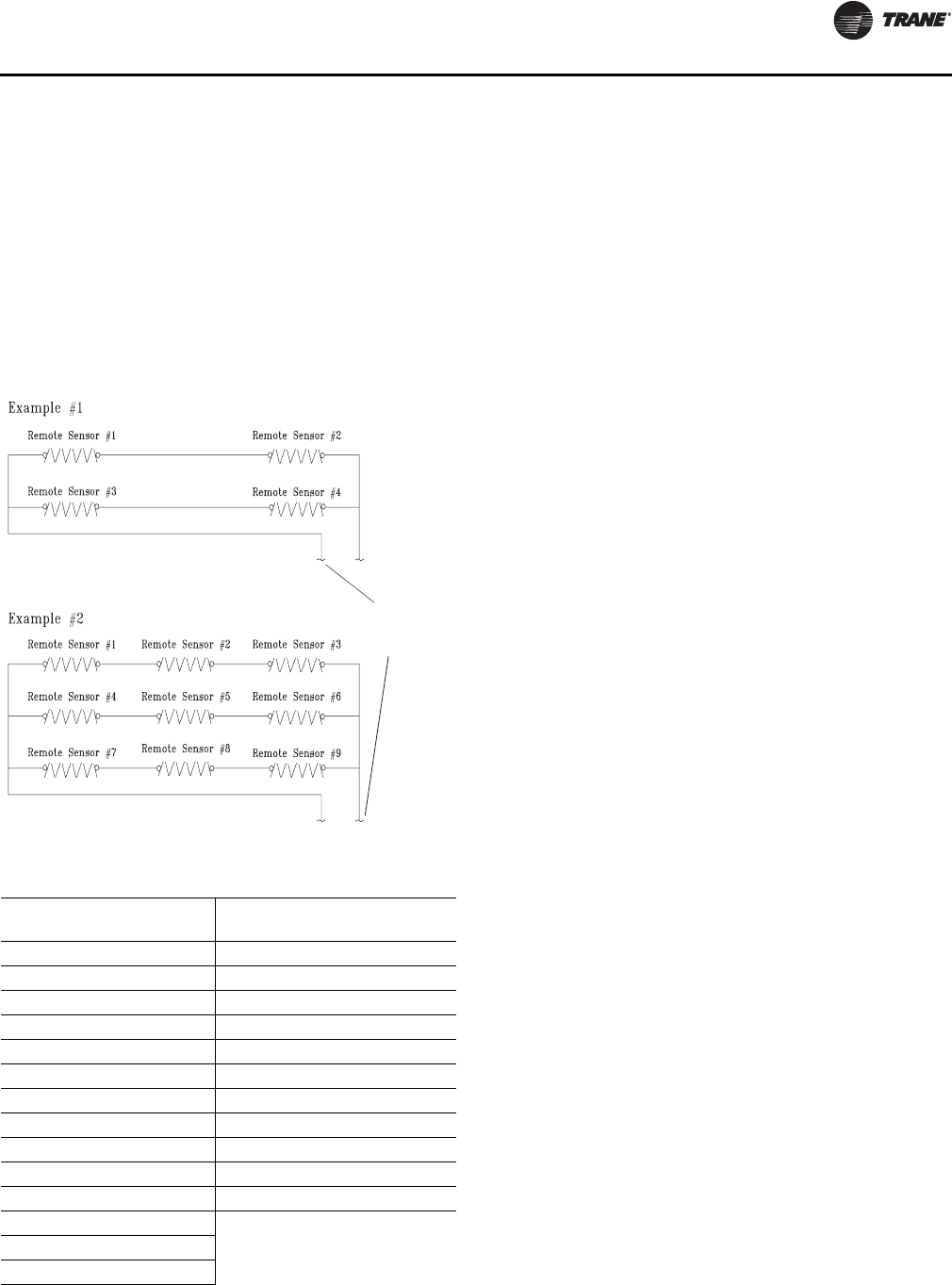
Installation Electrical
RT-SVX34H-EN 37
Space Temperature Averaging
Space temperature averaging is accomplished by wiring a
number of remote sensors in a series/parallel circuit.
The fewest number of sensors required to accomplish
space temperature averaging is four. Example #1
illustrates two series circuits with two sensors in each
circuit wired in parallel. Any number squared, is the
number of remote sensors required. Example #2
illustrates three sensors squared in a series/parallel circuit.
NSB panel remote sensors must use twisted/shielded
cable.
Figure 33. Space temperature averaging
Table 16. Temperature vs. resistance (temperature vs.
resistance coefficient is negative)
Degrees
F° Nominal
Resistance Degrees
F° Nominal
Resistance
-20° 170.1 K - Ohms 50° 19.96 K - Ohms
-15° 143.5 K - Ohms 55° 17.47 K - Ohms
-10° 121.4 K - Ohms 60° 15.33 K - Ohms
-5° 103.0 K - Ohms 65° 13.49 K - Ohms
0° 87.56 K - Ohms 70° 11.89 K - Ohms
5° 74.65 K - Ohms 75° 10.50 K - Ohms
10° 63.80 K - Ohms 80° 9.297 K - Ohms
15° 54.66 K - Ohms 85° 8.247 K - Ohms
20° 46.94 K - Ohms 90° 7.330 K - Ohms
25° 40.40 K - Ohms 95° 6.528 K - Ohms
30° 34.85 K - Ohms 100° 5.824 K - Ohms
35° 30.18 K - Ohms
40° 26.22 K - Ohms
45° 22.85 K - Ohms
To RTRM J6-1 and J6-2
or to ZSM terminals 1
and 2 or NSB panel terminals
S1 and S2. Shield to terminal 11
38 RT-SVX34H-EN
Installation Piping
General Requirements
All internal gas piping for YC* rooftop units are factory
installed and leak tested. Once the unit is set into place, a
gas supply line must be field installed and connected to the
gas train located inside the gas heat compartment.
Access holes are provided on the unit as shown in
Figure 11, p. 19 to accommodate side panel entry.
Following the guidelines listed below will enhance both
the installation and operation of the furnace.
Note: In the absence of local codes, the installation must
conform with the American National Standard
Z223.1a of the National Fuel Gas Code, (latest
edition).
1. To assure sufficient gas pressure at the unit, use
Table 18, p. 39 to determine the appropriate gas pipe
size for the heating capacity listed on the unit's
nameplate.
If a gas line already exists, verify that it is sized large
enough (Table 18, p. 39) to handle the additional
furnace capacity.
2. Take all branch piping from any main gas line from the
top at 90 degrees or side at 45 degrees to prevent
moisture from being drawn in with the gas.
3. Ensure that all piping connections are adequately
coated with joint sealant and properly tightened. Use a
piping compound that is resistant to liquid petroleum
gases.
4. Provide a drip leg near the unit.
5. Install a pressure regulator at the unit that is adequate
to maintain 6" w.c. for natural gas and 11" w.c. for LP
gas while the unit is operating in the “High Heat”
mode. A minimum inlet gas pressure of 2.5" w.c. for
natural gas and 8" w.c. for LP gas is required while
operating in the “High Heat” mode.
Note: Gas pressure in excess of 14" w.c. or 0.5 psig will
damage the gas train.
6. Leak test the gas supply line using a soap-and-water
solution or equivalent before connecting it to the gas
train.
7. Pressure test the supply line before connecting it to the
unit to prevent possible gas valve damage and the
unsafe operating conditions that will result.
Note: Do not rely on gas train shutoff valves to isolate
the unit while conducting gas pressure/leak
test. These valves are not designed to
withstand pressures in excess of 14" w.c. or 0.5
psig.
Connecting the Gas Supply Line to the
Furnace Gas Train
Follow the steps below to complete the installation
between the supply gas line and the furnace. Refer to
Figure 34, p. 39 for the Gas Train configuration.
1. Connect the supply gas piping using a “ground-joint”
type union to the furnace gas train and check for leaks.
2. Provide adequate support for the field installed gas
piping to avoid stressing the gas train and controls.
3. Adjust the inlet supply gas pressure to the
recommended 6" for natural gas or 11" w.c. for LP gas.
WARNING
Hazardous Gases and Flammable Vapors!
Exposure to hazardous gases from fuel substances have
been shown to cause cancer, birth defects or other
reproductive harm. Improper installation, adjustment,
alteration, service or use of this product could cause
flammable mixtures or lead to excessive carbon
monoxide. To avoid hazardous gases and flammable
vapors follow proper installation and set up of this
product and all warnings as provided in this manual.
Failure to follow all instructions could result in death or
serious injury.
NOTICE:
Gas Valve Damage!
• Failure to use a pressure regulating device will result
in incorrect gas pressures. This can cause erratic
operation due to gas pressure fluctuations as well as
damage to the gas valve.
• Oversizing the regulator will cause irregular pulsating
flame patterns, burner rumble, potential flame
outages, as well as possible gas valve damage.
WARNING
Hazard of Explosion!
Never use an open flame to detect gas leaks. It could
result in an explosion. Use a leak test solution for leak
testing. Failure to follow recommended safe leak test
procedures could result in death or serious injury or
equipment or property-only-damage.
Table 17. Specific gravity multiplier
Specific Gravity Multiplier
0.5 1.1
0.55 1.04
0.6 1
0.65 0.96
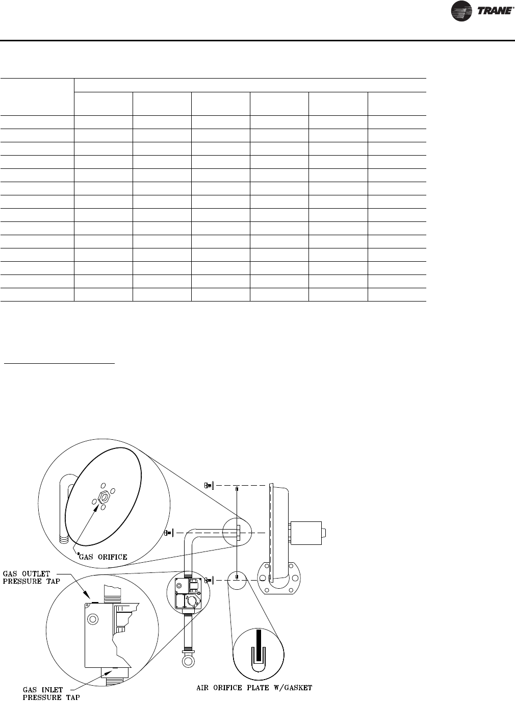
Installation Piping
RT-SVX34H-EN 39
Table 18. Sizing natural gas pipe mains and branches
Gas Input (Cubic Feet/Hour)*
Gas Supply Pipe
Run (ft) 1-1/4” Pipe 1-1/2” Pipe 2" Pipe 2-1/2” Pipe 3"Pipe 4"Pipe
10 1050 1600 3050 4800 8500 17500
20 730 1100 2100 3300 5900 12000
30 590 890 1650 2700 4700 9700
40 500 760 1450 2300 4100 8300
50 440 670 1270 2000 3600 7400
60 400 610 1150 1850 3250 6800
70 370 560 1050 1700 3000 6200
80 350 530 990 1600 2800 5800
90 320 490 930 1500 2600 5400
100 305 460 870 1400 2500 5100
125 275 410 780 1250 2200 4500
150 250 380 710 1130 2000 4100
175 225 350 650 1050 1850 3800
200 210 320 610 980 1700 3500
Notes:
1. If more than one unit is served by the same main gas supply, consider the total gas input (cubic feet/hr.) and the total
length when determining the appropriate gas pipe size.
2. Obtain the Specific Gravity and BTU/Cu.Ft. from the gas company.
3. The following example demonstrates the considerations necessary when determining the actual pipe size.
Example: A 40' pipe run is needed to connect a unit with a 500 MBH furnace to a natural gas supply having a rating of 1,000
BTU/Cu.Ft. and a specific gravity of 0.60
Cu.Ft/Hour = Furnace MBH Input
Gas BTU/Cu.Ft. X Multiplier Table 17, p. 38
Cu.Ft/Hour = 500 Table 18 indicates that a 1-1/4” pipe is required.
*Table is based on a specific gravity of 0.60. Use Table 17, p. 38 or the specific gravity of the local gas supply.
Figure 34. Gas train configuration for low heat units
(high heat units utilize two gas trains.)
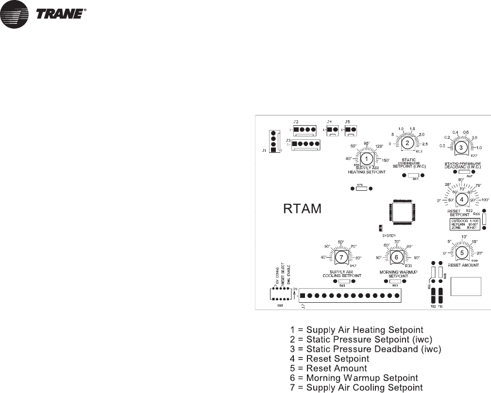
40 RT-SVX34H-EN
Startup
Unit Control Modules
RTRM - ReliaTel™ Refrigeration Module
The RTRM is the main information receiving module. It
interprets the information received from all other unit
modules, sensors, remote panels, customer binary
contacts and responds by activating the various unit
components to satisfy the applicable request for
economizing, cooling, heating, exhaust, ventilation.
The RTRM configuration is set through the wire harness to
function within one of six system applications:
1. Constant Volume Supply Air with No Heat.
2. Constant Volume Supply Air with Gas or Electric Heat.
3. Variable Supply Air Volume with No Heat.
4. Variable Supply Air Volume with Gas or Electric Heat.
5. Single Zone Variable Supply Air Volume with No Heat.
6. Single Zone Variable Supply Air Volume with Gas or
Electric Heat.
ECA/RTEM - Economizer Actuator/ReliaTel
Economizer Module (Optional)
The ECA/RTEM monitors the mixed air temperature,
return air temperature, minimum position setpoint (local
or remote), ambient dry bulb/enthalpy sensor or
comparative humidity (return air humidity against
ambient humidity) sensors, if selected, to control the
dampers to an accuracy of +/- 5% of the stroke. The
actuator is spring returned (FA closed, RA opened) any
time power is lost to the unit. Refer to “Mechanical Cooling
with an Economizer,” p. 56 for the proper potentiometer
settings for dry bulb/Enthalpy control.
Note: The ECA/RTEM control module is mounted on the
actuator. Units with the ultra-low-leak economizer
option have their ECA control module mounted to
a panel adjacent to the RA damper.
EBA - Exhaust Blade Actuator (Optional)
If the unit is ordered with tracking power exhaust, the EBA
will track the economizer damper position as long as the
active exhaust fan setpoint has been exceeded - set via
RTOM, through BAS, or calculated (SZ VAV only). The
actuator limits the maximum travel of the exhaust
barometric damper. The exhaust blade actuator is spring
returned and is closed any time power is lost to the unit.
RTAM - ReliaTel Air Handler Module
(Standard with Traditional VAV)
The RTAM receives information from the supply duct static
pressure transducer. Attached to the module are the
supply air heating potentiometer, supply air cooling
setpoint potentiometer, supply pressure setpoint
potentiometer, static pressure deadband potentiometer,
morning warm-up setpoint potentiometer, reset setpoint
potentiometer, and 5 DIP switches. (See Figure 35, p. 40.)
DIP Switches:
Switch 1 is “ON” for VFD's.
Switch 2 is “OFF” for VAV.
Switch 3 and 4 operation are explained under “supply air
temperature reset”.
Switch 5 is “OFF” for DWU Disabled and “ON” for DWU
Enabled.
Figure 35. RTAM module
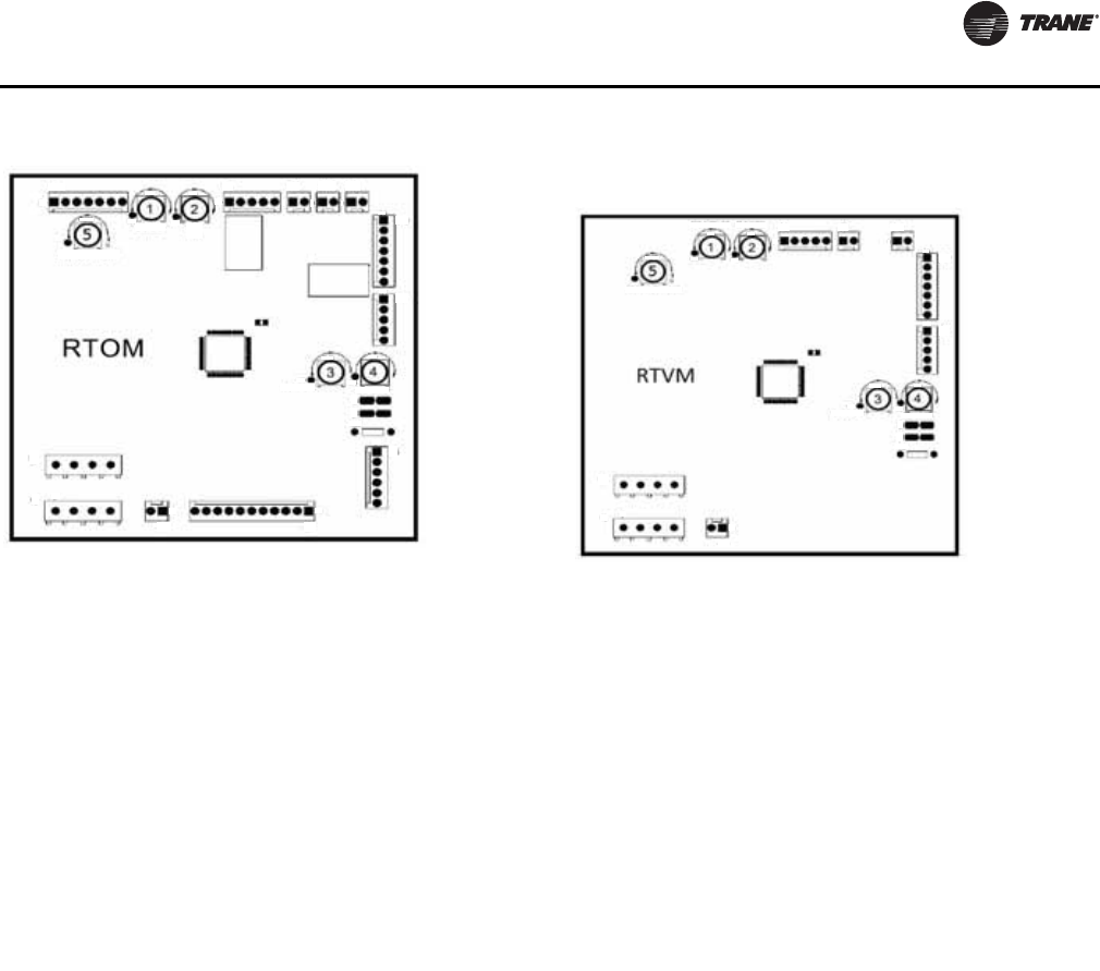
Startup
RT-SVX34H-EN 41
The RTAM module provides a 0 to 10 Vdc output to control
the Variable Frequency Drive. DIP switches located on the
RTAM configures the unit to use the output for a VFD.
Customer changeover input from Low Voltage Terminal
Board (LTB5) activates VAV heating. The Supply Air
Heating setpoint must be set to the desired discharge air
temperature for heating. This VAV heating mode is
available only with modulating gas heat units. In this mode
the gas heaters modulate and the supply air pressure
control remains active to satisfy the zone settings.
For constant volume (CV) units with modulating gas heat
using a conventional thermostat or for Single Zone VAV
units with modulating gas heat, the Discharge Air SP on
the RTOM must be set to desired discharge air
temperature in order for the unit to function properly. See
Figure 36, p. 41 For VAV units with modulating gas heat,
the Supply Air Heating Setpoint on the RTAM is used to
control the heat setpoint in the changeover heating mode.
ReliaTel Ventilation Module (RTVM)
The RTVM (Ventilation Module) provides a 2 to 10 Vdc
signal to control the Exhaust Blade Actuator in order to
relieve positive building pressure. The signal output will
be modulated based on the measured values from the
Space Pressure Transducer. The Space Pressure
Calibration Solenoid will ensure that the RTVM reads a
differential pressure between the building pressure and
atmospheric pressure. The Space Pressure Setpoint and
Space Pressure Deadband are set by adjusting
potentiometers located on the RTVM. Also, units
configured for Single Zone VAV control with Demand
Controlled ventilation will require an RTVM for the
additional, required Outside Air damper minimum
position setpoint potentiometers.
Units configured with the Fresh Air Measurement (Traq)
option will require a RTVM for required sensors and
setpoints to perform Traq airflow control. The Airflow
Sensor input, Minimum Outside Air CFM Setpoints
(Design and DCV), and Outside Airflow Adjustment
Setpoint are all provided by the RTVM. The RTVM takes the
airflow sensor voltage, converts it to airflow (CFM) and
calculates a Traq outside air minimum OA damper position
Figure 36. RTOM module
J8 J4 J9 J10 J11
J12
J3
J6
J7J5
J1 J2
DA COOL/FAN SPD
DA HEAT EXH
FAN
SA REHEAT DEHUMID
1- 111
1-
1-
1-
1-
TP4
TP5
R41
R130
R46
-1
-1
-1
TB2 TB1
R136 TP2 TP3
R42 R40
1 = Discharge Air Heat Setpoint**
2 = Exhaust Fan Enable Setpoint
3 = Supply Air Reheat Setpoint
4 = Dehumidication (%) Setpoint
5 = Discharge Air Cool Setpoint LL***
**Discharge Air Heat Setpoint is required for Single Zone
VAV units with modulating heat or traditional
Constant Volume units with modulating heat and a
conventional thermostat control.
***Discharge Air Cool Setpoint is required for Single
Zone VAV operation.
Figure 37. RTVM module
DA COOL/FAN SPD
SA REHEAT DEHUMID
SPC PRESS DB SPC PRESS
R136
J4 J9 J11
J12
J3
J1 J2
TP2 TP3
R42 R40
1- 1 1
1-
TP4
TP5
R130 R41
TB2 TB1
R46
-1
-1
J5
1-
1 = Space Pressure Deadband (iwc)
2 = Space Pressure Setpoint (iwc)
3* = R130 = Design minimum OA ow Setpoint
4* = R41 =DCV Minimum OA ow Setpoint
3** = R130 (SA REHEAT SP) = Design
Minimum Position at Minimum Fan
Speed Command
4** = R41 (DEHUMID) = DCV Minimum
Position at Minimum Fan Speed
Command
5** = R136 (DA COOL/FAN SPD) = Design
Minimum Position at 50% Fan Speed
Command
* Setpoints for units with TRAQ
** Setpoints only required for Single Zone VAV units with Demand
Controlled Ventilation installed.
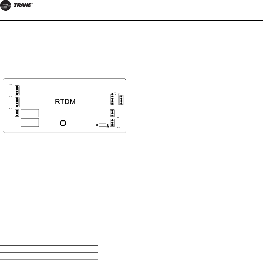
Startup
42 RT-SVX34H-EN
to maintain the desired adjustable CFM setpoint value.
The airflow can be adjusted for altitude differences with
the Outside Airflow Adjustment Setpoint.
ReliaTel Dehumidification Module
(RTDM)
The RTDM provides a pulsed signal output to control the
Cooling and Reheat Modulating Valves. The RTDM will
also monitor the Entering Evaporator Temperature as well
as protect against a low refrigerant pressure in the reheat
circuit.
Conventional Thermostat Connections
(Available Only with CV)
This feature allows conventional thermostats to be used in
conjunction with the RTRM on Constant Volume
Applications only. It utilizes the conventional wiring
scheme of R, Y1, Y2, W1, W2/X, and G. Refer to Figure 22,
p. 33 for conventional thermostat connections. Applicable
thermostats to be used with the conventional thermostat
inputs are:
TCI - Trane Communication Interface
(Optional)
This module is used when the application calls for an ICS
building management type control system. It allows the
control and monitoring of the system through a Trane
Tracer™ panel. The module can be ordered from the
factory or ordered as a kit to be field installed. Follow the
installation instructions that ship with each kit when field
installation is necessary.
LCI - LonTalk® Communication Interface
(Optional)
This module is used when the application calls for a
LonTalk building management type control system. It
allows the control and monitoring of the system through
a Trane Tracer Summit panel or 3rd party LonTalk system.
The module can be ordered from the factory or ordered as
a kit to be field installed. Follow the installation
instructions that ship with each kit when field installation
is necessary.
BCI - BACnet® Communication Interface
(Optional)
This module is used when the application calls for a
BACnet building management type control system. It
allows the control and monitoring of the system through
a Trane Tracer SC panel or 3rd party BACnet system. The
module can be ordered from the factory or ordered as a kit
to be field installed. Follow the installations instructions
that ship with each kit when field installation is necessary.
Trane Wireless Comm Interface (WCI)
The Trane® Wireless Comm Interface (WCI) is the perfect
alternative to Trane’s BACnet™ wired communication
links (for example, Comm links between a Tracer™ SC and
a Tracer UC400). Minimizing communication wire used
between terminal products, zone sensors, and system
controllers has substantial benefits. Installation time and
associated risks are reduced. Projects are completed with
fewer disruptions. Future re-configurations, expansions,
and upgrades are easier and more cost effective.
TD5 Display - 5" Touchscreen Display
The Tracer TD5 display is an optional display module that
operates in conjunction with the ReliaTel Controller and
allows you to view data and make operational changes.
More information on the Tracer TD5 Display can be found
in Installation, Operation, and Maintenance Manual, RT-
SVX49*-EN.
Figure 38. RTDM module
Table 19. Thermostats
Vendor Part # Trane Part #
Honeywell T7300
Honeywell T874D1082 BAYSTAT011
Enerstat MS-1N BAYSTAT003

Startup
RT-SVX34H-EN 43
System Operation
Economizer Operation with a
Conventional Thermostat (CV Only)
If the ambient conditions are suitable for economizer
operation, the economizer is activated as the 1st step of
cooling from Y1. The dampers are controlled to provide a
supply air temperature of 50° F +/- 5° F. If the economizer
is disabled due to ambient conditions, the 1st stage of
mechanical cooling is activated.
While economizing, if an additional stage of cooling is
activated from Y2, the 1st stage of mechanical cooling is
activated. If the economizer is disabled due to ambient
conditions, the 2nd stage of mechanical cooling is
activated.
The supply fan is activated from the G terminal and will
cycle with a call for heat or cooling if in the “Auto” mode.
It wi ll run continuously in the “On” mode regard less of any
other system demand.
On gas heat units, first and second stages are activated by
the W1 and W2 terminals on the CTI. On electric heat units,
only two stages of heat are available. If the W2 terminal is
activated without activating the W1 terminal, the RTRM
will bring on both stages of electric heat.
The Conventional Thermostat connections can also be
utilized as a generic building automation system interface
for constant volume ICS applications. Due to the limited
heating and cooling steps when using a conventional
thermostat, compressor staging will vary on units with
three compressors.
Note: If a conventional thermostat is used with a unit that
has modulating gas heat, the unit will control to the
Discharge Air SP potentiometer on the RTOM when
heating with a W1 call only. The unit will go to high
fire with W1 + W2.
Microelectronic Control Features
1. Anti short cycle timer (ASCT) function. Compressor
operation is programmed for 3 minutes of minimum
“ON” time, and 3 minutes of minimum “OFF” time.
Enhances compressor reliability, and ensures proper
oil return.
Note: Compressor cycle rate minimization, extends
compressor life expectancy. Minimizes damaging
compressor inrush current, and guards against
short cycling.
2. Delay between stages timer function. When combined
with a standard Zone Sensor Module, the Reliatel
Refrigeration Module (RTRM) provides a 10 second
minimum “ON” delay for compressor staging.
3. Built in Fan Delay Relay function for Constant Volume
and Single Zone VAV units. When the fan mode switch
on the Zone Sensor Module is set in the auto position,
the RTRM provides individual supply fan timing
sequences for each system in heating and cooling. The
RTRM provides different timing sequences for Gas
Heat units and Cooling only units.
4. Low ambient cooling to 0°F with Frostat™.
5. Built in electric heat staging, provides a 10 second
“ON” delay between resistance heat stages.
6. Economizer preferred cooling allows fully integrated
economizer operation with mechanical cooling if
actually needed.
On Constant Volume and Single Zone VAV
applications, a 3 minute delay allows the RTRM to
evaluate the rate of change in the zone. If the zone
temperature is dropping faster than acceptable
parameters, the compressor(s) will not be required to
operate.
7. Free night setback allows the unit to enter an
unoccupied mode by simply shorting across terminals
RTRM J6-11 and J6-12. The short can be achieved by a
set of dry contacts or a time clock. Once this short has
been made the unit will close the economizer dampers,
go from continuous fan to auto fan operation, and:
CV or SZ VAV Unit w/Mechanical ZSM
If the unit has a valid cooling and heating setpoint, the
setup/setback is a minimum of 7°F.
If the unit does not have both setpoints, the setup/
setback is 0°.
If the unit has neither setpoint, the unoccupied cooling/
heating setpoints will be 74°F/71°F.
If the unit is configured as a Constant Volume unit and
a conventional thermostat is used, this input is ignored
and the unit will respond to thermostat requests as
during normal occupied mode.
VAV unit w/o ICS or NSB energizes heating if the space
temperature drops to 10°F below the MWU setpoint
but not less than 50°F
This option can not be used with programmable ZSM
or with an ICSTM system.
8. Low pressure cutouts on all compressors have been
added to insure compressor reliability in low
refrigerant flow situations. The compressor(s) will
lockout after four consecutive low pressure control
trips during the compressor minimum 3 minute “on”
time. The lockout will have to be manual reset as
explained in this document.
Startup
44 RT-SVX34H-EN
Economizer Operation with CV Controls
The control point for the economizer is designed to control
at least 1.5°F below the cooling setpoint or 1.5°F above the
heating setpoint, whichever produces the highest
economizer control setpoint.
Example:
Heating Setpoint = 68°F
Cooling Setpoint = 70°F
The control temperature for the economizer will be 1.5°F
above the heating setpoint
due to it producing the least amount of offset.
Heating Setpoint = 55°F
Cooling Setpoint = 75°F
Because of the spread between the heating and cooling
setpoints, the control will choose to control the
economizer at an offset temperature of 1.5°F below the
cooling setpoint. This will be the highest resulting control
setpoint temperature while maintaining the least amount
of offset.
The percentage that the economizer dampers open is
based on two factors:
1. The zone temperature minus the economizer setpoint,
and,
2. The zone temperature minus the outdoor air
temperature.
Note: Table 20 lists the percentages the dampers will
open based on these conditions.
While economizing, if the supply air temperature falls
below 50°F, the damper will not be allowed to open any
further until the supply air temperature rises above 50°F. If
the supply air temperature falls below 45°F, the dampers
will be driven to minimum position and held there until the
supply air temperature rises above 50°F.
The mechanical cooling is disabled while in an
economizing state until two conditions are met:
1. The economizer dampers have been fully open for
three minutes, and;
2. The calculated rate of change in the zone temperature
is less than 12°F per hour.
If the economizer is disabled due to unsuitable conditions,
the economizer is at the selected minimum position when
the supply fan is “On”, and is closed when the supply fan
is “Off”. The mechanical cooling will cycle as though the
unit had no economizer.
Modulating Power Exhaust
If the unit is equipped with the modulating power exhaust
option, the power exhaust actuator will follow the position
of the economizer actuator.
Mechanical Cooling without an
Economizer (CV and SZ VAV)
Mechanical cooling is used to maintain the zone
temperature. The RTRM is designed to limit the
compressor cycle rates to within 10 cycles per hour based
on the minimum compressor “on” and “off” times.
It stages the mechanical cooling to control the zone
temperature to within +/- 2°F of the sensor setpoint at the
sensed location. Table 21 lists the compressor staging
sequence for standard efficiency units.
For high efficiency units there are three separate staging
sequences which determine the staging of 3 compressors
within each sequence. Each call for cool will operate within
a given sequence and the next call for cool will operate in
the next sequence. Lead/Lag operation is taken into
consideration with these 3 staging sequences and will be
active when Lead/Lag is configured. Table 22 lists the
compressor staging sequence for high efficiency units.
Table 20. Percent of damper travel
Zone Temp - Econ Setpoint °F
Zone - ODT 0.0-0.5 0.5-1.0 1.0-2.0 2.0-3.0 3.0-5.0 >5.0
0 - 7 F 0% 3% 9% 30% 90% 100%
7 - 14 F 0% 2% 6% 20% 60% 100%
> 14 F 0% 1% 3% 10% 30% 100%
Table 21. Compressor staging with lead/lag disabled -
std efficiency units
“ON” “OFF”
Unit Model Step 1 Step 2 Step 3 Step 3 Step 2 Step 1
27.5 - 35 CPR 11CPR 1, 2 N/A N/A CPR 1, 2 CPR 11
40 CPR 12CPR 23CPR 1, 2 CPR 1, 2 CPR 23CPR 12
50 CPR 12CPR
2,34CPR 1,
2, 3 CPR 1,
2, 3 CPR 2,
34CPR 12
Notes:
1. Single circuit, dual manifolded compressors
2. Number one refrigeration circuit, Standalone compressor, is “On”.
3. First stage is off. Number two refrigeration circuit, standalone
compressor, is “On”
4. First Stage is “Off”, Number two refrigeration circuit, manifolded
compressor pair operating simultaneously, is “On”.
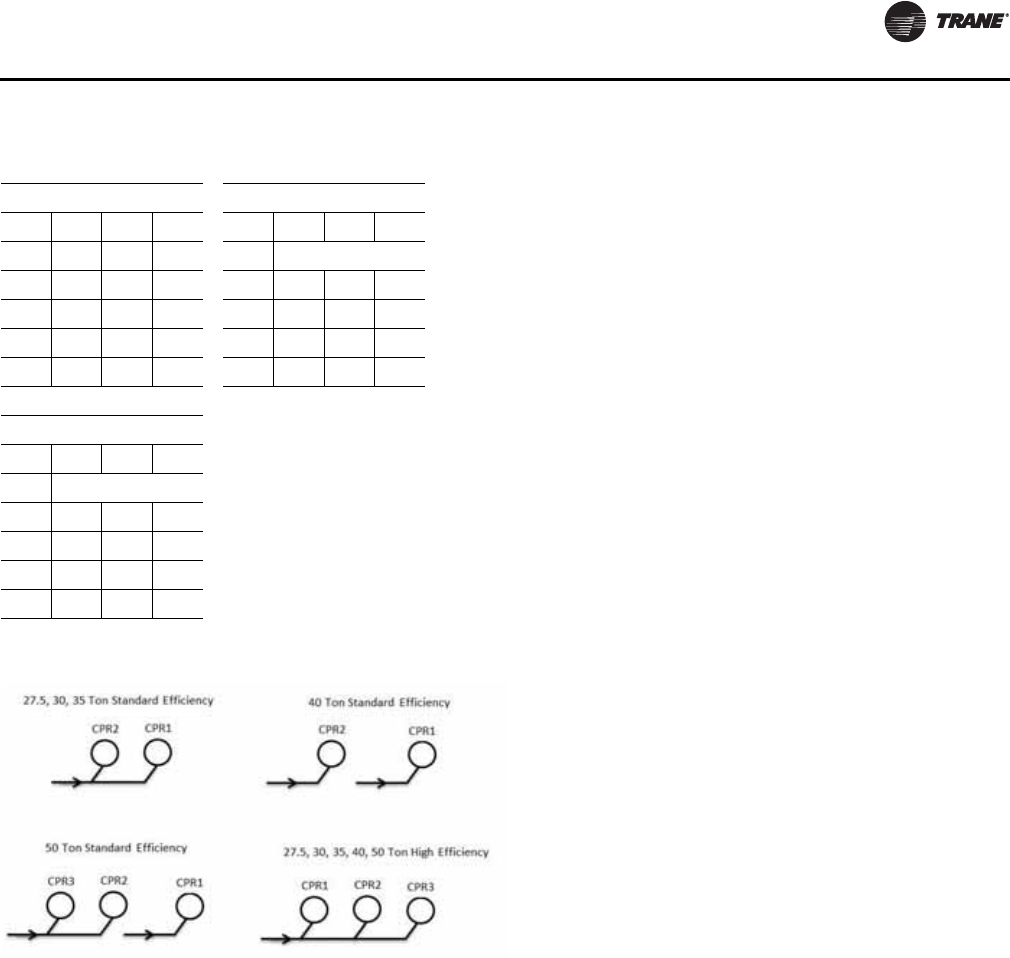
Startup
RT-SVX34H-EN 45
Zone Temperature - Occupied Cooling (CV
and SZ VAV)
When the unit is in the cooling mode and the zone
temperature raises above the cooling setpoint control
band, the economizer and the compressor stages will be
cycled as required by the zone sensor, remote panel, or
Tracer®. For SZ VAV control, the fan capacity will also be
controlled in order to meet the zone cooling demand.
Zone Temperature - Occupied Heating (CV
and SZ VAV)
When the unit is in the heating mode and the zone
temperature falls below the heating setpoint control band,
the necessary stages of heat will cycle to raise the
temperature to within the setpoint control band. For SZ
VAV, the fan capacity will also be controlled in order to
meet the zone heating demand.
Supply Fan (CV and SZ VAV)
When the Fan Selection Switch is in the “AUTO” position
and a call for cooling is initiated, the supply fan will delay
starting for approximately one second on traditional CV
units. For SZ VAV units, the supply fan will be controlled
ON based on the zone cooling demand. Once ON, the unit
will begin staging cooling capacity (economizer and/or
compressors) in order to meet the discharge air
requirements. Once the zone has been satisfied, the
supply fan will be controlled OFF. When the Fan Selection
Switch is in the “ON” position, the supply fan will run
continuously. If airflow through the unit is not proven by
the differential pressure switch (factory setpoint 0.15“w.c.)
within 40 seconds nominally, the RTRM will shut off all
mechanical operations, lock the system out, send a
diagnostic to ICS, and the SERVICE LED output will pulse.
The system will remain locked out until a reset is initiated
either manually or through ICS or a mode transition from
OFF to a non-OFF mode.
Supply Air Tempering (CV and SZ VAV)
CV Units with Staged Heat
This function allows the supply air temperature to be
maintained within a low limit parameter during minimum
ventilation periods. For CV units configured with a Staged
Heat design (Electric or Gas) and Supply Air Tempering
operation enabled, if the following items are true, the unit
will enter Supply Air Tempering mode:
1. The supply fan is ON.
2. The unit is in Occupied mode.
3. Zone Temp. is less than the active Cooling setpoint.
4. The unit is in Heat mode but is not actively heating OR
5. The unit is in AUTO-COOL mode but not actively
cooling and cooling capacity has been OFF for 5
minutes.
Once the above conditions are met, if the supply air
temperature drops to 10°F BELOW the Occupied Heating
Zone Temperature Setpoint, the SA Tempering function
will bring ON one stage of gas or electric heat.
Once SA Tempering is active, heating will be turned OFF if
the Supply Air Temperature rises to 10°F ABOVE the Active
Occupied Zone Heating Setpoint, or the Zone Temperature
rises to the Active Zone Cooling Setpoint. Also, if the Zone
Heat Control function is calling for 1 or more stages of
Heat, Tempering will be discontinued and the unit will
stage additional heating to meet the current demand.
When an economizer is installed, air tempering is allowed
with ICSTM when the fan system switch is in the “ON”
position with no call for heating. The same conditions
must be met as described above for entering and leaving
Tempering operation.
Table 22. Compressor staging sequence - high efficiency
units
Sequence 1 Sequence 2
Stage CPR 1CPR 2CPR 3 Stage CPR 1CPR 2CPR 3
1 ON OFF OFF 1 Start at Stage 2
2 OFF ON OFF 2 OFF ON OFF
3 ONONOFF 3 ON ONOFF
4 OFF ON ON 4 OFF ON ON
5 ON ON ON 5 ON ON ON
Sequence 3
Stage CPR 1 CPR2 CPR3
1 Start at Stage 2
2OFFOFFON
3ONOFFON
4 OFF ON ON
5 ONONON
Figure 39. Compressors
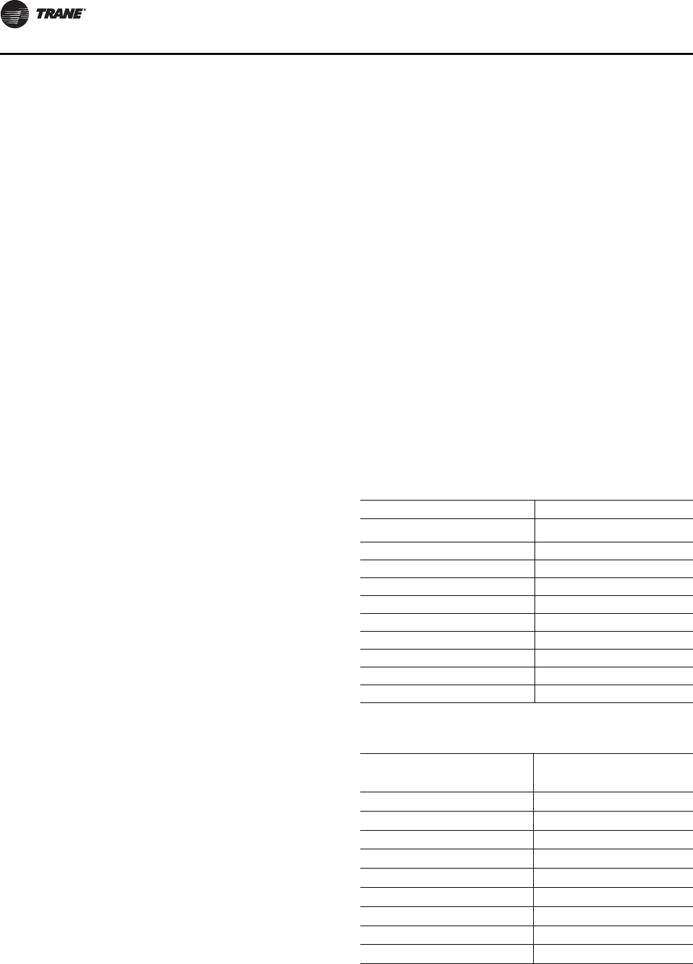
Startup
46 RT-SVX34H-EN
CV Units with Modulating Heat
On units with Modulating Gas Heat, Supply Air Tempering
is inherent to the Modulating Heat design and does not
require any additional configuration/enabling. Modulating
Heat Tempering is accomplished by allowing the unit to
return to heating if the Zone is marginally satisfied and the
Supply Air temperature begins to fall. The following
conditions must be true to enable the unit to perform
“Tempering”:
1. The supply fan is ON.
2. The unit is in Occupied mode.
3. Zone Temp. is less than the active Cooling setpoint.
4. The unit is in Heat mode but is not actively heating OR
5. The unit is in AUTO-COOL mode but not actively
cooling and cooling capacity has been OFF for 5
minutes.
Once the above conditions are met, and the supply air
temperature drops below the ZHSP - 10°F, the unit will
transition back into active heating operation and will begin
to control the modulating heat output to maintain the
supply air temperature.
Once the unit has entered into Tempering mode, the unit
will leave active heating either by normal heat termination
as determined by the heating control algorithm or when
the Zone Temperature reaches the active ZCSP.
SZ VAV Units with Staged Heat
For SZ VAV units configured with a Staged Heating type,
the Supply Air Tempering function will operate as on a CV
unit with Staged Heat.
SZ VAV Units with Modulating Heat
For units configured with a Modulating Heat type,
“Tempering” is an extension of normal Heating control
which allows a transition from inactive “Auto-Cool” mode
to Heating based on supply air temperature if the Zone
Temperature is in control. The following conditions must
be true to allow the unit to enter Supply Air Tempering:
1. Supply Fan is ON.
2. The unit is in Occupied mode.
3. The unit is operating in Auto-Cool Mode.
4. Cooling has been inactive for 5 minutes.
When the above conditions are true, Tempering will be
allowed when the Supply Air Temperature falls below the
user selectable Minimum Supply Air Cooling Setpoint
(minus deadband) as long as the Zone Temperature is <
ZCSP - 1°F. Once the unit transitions into “Tempering” the
unit will transition to normal heating control and will
control the supply air temperature between the minimum
and maximum supply air setpoints.
If the Zone Temperature rises above the ZCSP during
“Tempering” the unit will de-energize Heating and
“Tempering” will be disabled until conditions allow for it
again. Normal Auto-Changeover requirements will be in
control to allow the unit to transition into Active Cool
mode.
Variable Air Volume Applications
(Single Zone VAV)
Supply Fan Output Control
Units configured for Single Zone VAV will include a VFD
controlled supply fan motor which will be controlled via
the 0-10Vdc Indoor Fan Speed output located on the RTOM
and the RTRM Supply Fan output. With the RTRM Supply
Fan output energized and the RTOM Indoor Fan Speed
output at 0Vdc the fan speed output is 33% (20Hz) for
cooling mode and 58% (35Hz) for heating modes from the
VFD motor and at 10Vdc the fan speed output is 100%
(60Hz). The control will scale the 0-10Vdc output from the
RTOM linearly to control to 38%-100% controllable range
based on the space heating or cooling demand.
Minimum Supply Fan Output
Refer to the table below for details on minimum supply fan
output signals associated with each unit function. Note
that each value represents the actual Fan Output %.
Table 23. Fan output - standard efficiency
Function Minimum Fan Output %
Ventilation Only 58%
Economizer Cooling 58%
Cool 1 (C1 Energized) 58%
Cool 2 (C1 or C2) 67%
Cool 3 (C1 + C2 Energized) 67%
SZVAV Modulating Heat 58%
CV Staged Heat 100%
SZVAV Modulating Heat Tempering 58%
CV Staged Heat Tempering 100%
Modulating Reheat 80%
Table 24. Fan output - high efficiency
Function Minimum Fan Output %
Ventilation Only 45%
Economizer Cooling 45%
Cool 1 45%
Cool 2 58%
Cool 3 67%
Cool 4 75%
Cool 5 75%
SZVAV Modulating Heat 58%
CV Staged Heat 100%
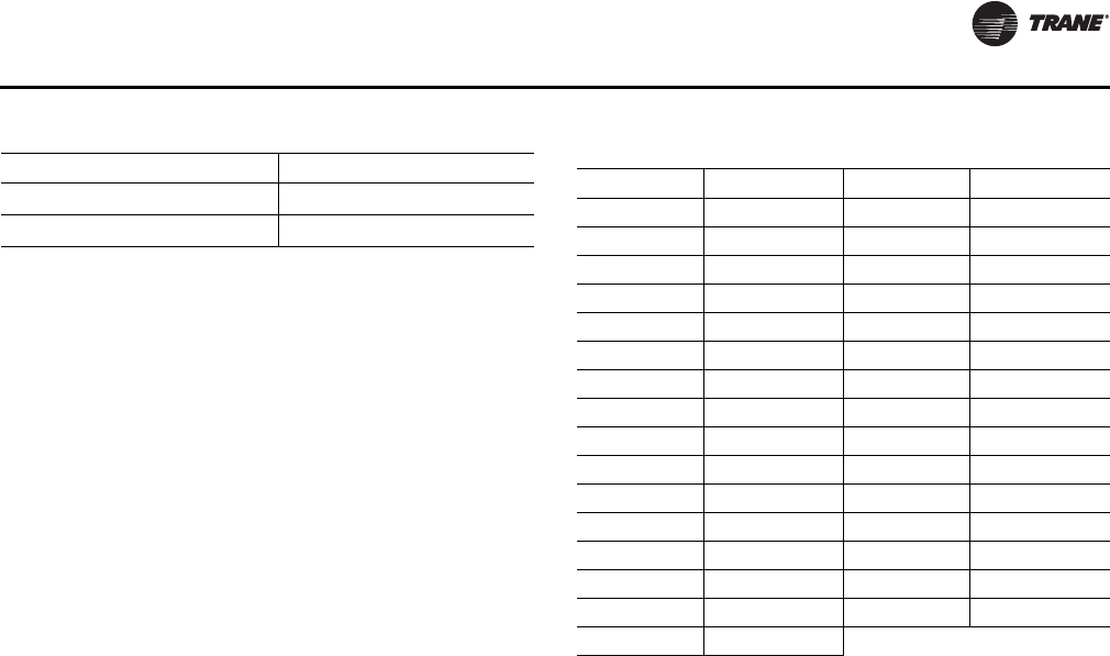
Startup
RT-SVX34H-EN 47
Supply Fan Mode Operation
Units configured for Single Zone VAV control will utilize
Supply Fan Mode selection as is currently implemented
into ReliaTel controls for normal Zone Control and will be
selectable between AUTO and ON via a connected Zone
Sensor module or through BAS/Network controllers.
Supply Fan Mode Auto Operation
For active Cooling, Heating, and Dehumidification
operation the Supply Fan will be commanded ON and will
ramp up to the appropriate minimum speed once the unit
determines that there is a request for capacity control.
Once the active request is cleared and all capacity is de-
energized normal supply fan off delays as implemented on
constant volume units will be in effect. During the Supply
Fan Off-Delay, the supply fan will remain energized for the
predetermined time at the previous unit function's
minimum speed. All other cases which would bring the
Supply Fan ON will function as on non-Single Zone VAV
units.
Supply Fan Mode ON Operation
For active unit control with the Supply Fan Mode set to ON,
the unit will energize the Supply Fan and hold the Fan
Speed output at minimum speed until there is a request for
the fan speed to increase. This will hold true for all cases
except during Unoccupied periods in which the Supply
Fan Mode is forced to AUTO and will operate the Supply
Fan as described above for all Cooling, Heating, and
Dehumidification requests.
Setpoint Arbitration
Single Zone VAV units will require traditional Zone
Heating (if Heat installed) and Cooling Setpoints that are
used constant volume units in addition to two new
setpoints: Discharge Air Cool (DA Cool - Fan SPD) and
Discharge Air Heat (DA Heat) Setpoint limits. The Zone
Heating and Cooling Setpoints will be selectable via the
existing RTRM customer connections for a Zone Sensor
panel and the DA Heat and Cool Setpoints will be customer
selectable via two onboard potentiometers on the RTOM
with ranges 50-150°F and 40-90°F respectively.
Table 26 and Table 25 below can be used as a reference
when setting the DA Heat (R42) and DA Cool - Fan SPD
(R136) setpoints on the RTOM.
Note: The recommended settings for these setpoints is
100°F for the DA Heat Setpoint and 50°F for the DA
Cool - Fan SPD Setpoint.
SZVAV Modulating Heat Tempering 58%
CV Staged Heat Tempering 100%
Modulating Reheat 80%
Table 24. Fan output - high efficiency Table 25. DA cool - fan SPD setpoint
Setpoint (°F) Voltage (Vdc) Setpoint (°F) Voltage (Vdc)
40 <0.1 56 1.7
41 0.2 57 1.75
42 0.3 58 1.83
43 0.45 59 1.9
44 0.55 60 1.95
45 0.7 61 2
46 0.8 62 2.05
47 0.95 63 2.1
48 1.05 64 2.13
49 1.15 65 2.17
50 1.25 66 2.21
51 1.3 67 2.27
52 1.35 68 2.3
53 1.45 69 2.35
54 1.55 70 >2.4
55 1.65
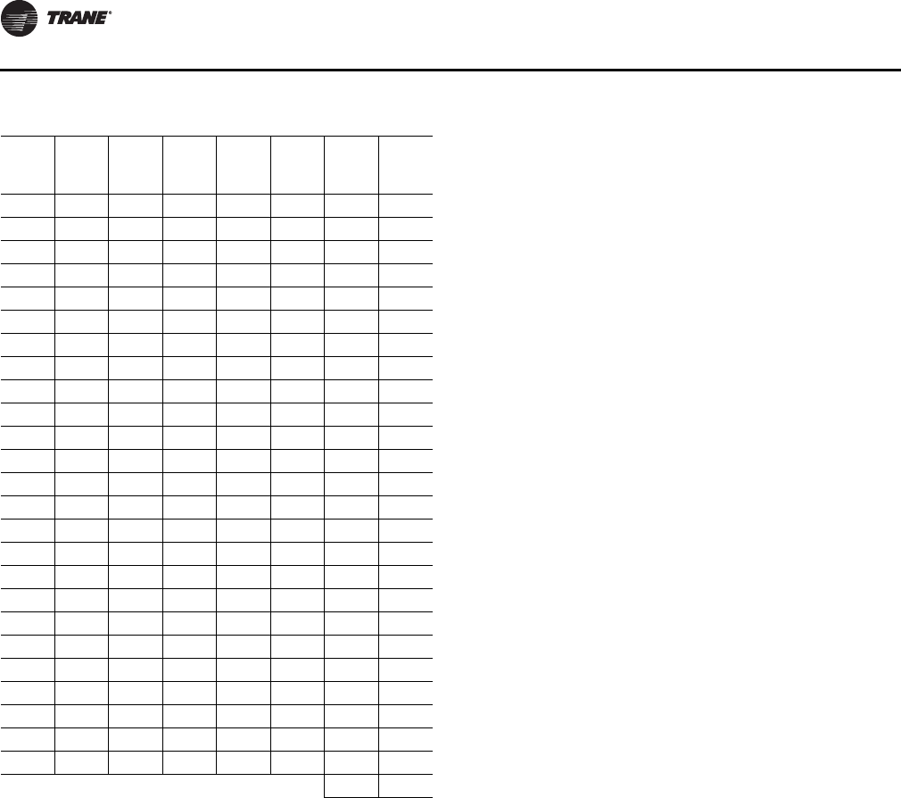
Startup
48 RT-SVX34H-EN
Note: The above potentiometer voltage readings can be
verified via the provided test points located next to
each potentiometer. Use a DC voltmeter to the Vdc
reading between those points and common.
Units Configured with the Outside Air
Measurement (Traq) Option
To make a minor correction to the Traq airflow (CFM)
reading that is calculated internally by the ReliaTel system,
an adjustment pot is available on the RTVM. This pot can
be used to correct for static “local” factors such as altitude.
Variable factors such as drift, temperature, humidity, and
other changing atmospheric conditions are corrected as
part of the conversion calculation.
The adjustment will typically be made in Service Test
mode in a step where the OA damper is being commanded
to the Traq OA Minimum Position Request with all required
Traq control inputs valid (i.e. sensors, setpoints, RTVM
board). The OA flow adjustment setpoint potentiometer
(R136) on the RTVM will be used to adjust the value up to
a factor of +/- 20% (0.80 to 1.20) Full counter-clockwise will
be – 20% and full clockwise will be + 20%. The
potentiometer will be set to the middle position (between
full CCW and full CW) in a “Deadband” area representing
no adjustment 0% (factor of 1.00) by default. The
adjustment will be applied linearly across the sensing
range of the airflow sensor which may produce
inaccuracies at airflow levels not close to the value at
which the calibration adjustment was made.
Sequence for Setting Calibration:
1. If unit is configured with DCV disconnect CO2 sensor
prior to powering unit. After calibration remove power
from unit and reconnect CO2 sensor.
2. Adjust the Design Minimum OA Flow Setpoint
potentiometer (R130/R41) on the RTVM to your desired
flow rate for minimum ventilation (See Table 27).
3. Initiate Service Test and step to the Minimum
Ventilation step. This will set the unit into a constant ID
fan speed and OA damper request to minimum
position. Minimum position will be from the Traq
calculation to maintain the OA flow at the setpoint.
4. Allow the damper position to settle to the desired flow
rate set by the setpoint.
5. Measure the OA flow rate via an air balancing
instrument.
6. Adjust the OA flow adjustment setpoint potentiometer
(R136) clockwise or counter-clockwise to “dial in” the
flow to match the instrument in Step 4 (See Table 28).
Table 26. DA heat setpoint
Volt-
age
(Vdc)
Set-
point
(ºF)
Volt-
age
(Vdc)
Set-
point
(ºF)
Volt-
age
(Vdc)
Set-
point
(ºF)
Volt-
age
(Vdc)
Set-
point
(ºF)
0.00 50 0.98 75 1.61 100 2.06 125
0.09 51 1.00 76 1.63 101 2.08 126
0.13 52 1.03 77 1.66 102 2.09 127
0.16 53 1.06 78 1.69 103 2.11 128
0.20 54 1.08 79 1.71 104 2.12 129
0.24 55 1.11 80 1.72 105 2.13 130
0.28 56 1.13 81 1.74 106 2.13 131
0.31 57 1.16 82 1.76 107 2.14 132
0.35 58 1.18 83 1.78 108 2.16 133
0.39 59 1.21 84 1.79 109 2.17 134
0.42 60 1.23 85 1.81 110 2.19 135
0.46 61 1.26 86 1.83 111 2.20 136
0.50 62 1.28 87 1.84 112 2.21 137
0.53 63 1.31 88 1.86 113 2.23 138
0.57 64 1.33 89 1.88 114 2.24 139
0.61 65 1.36 90 1.89 115 2.25 140
0.65 66 1.38 91 1.91 116 2.26 141
0.68 67 1.41 92 1.93 117 2.28 142
0.72 68 1.43 93 1.95 118 2.29 143
0.76 69 1.46 94 1.96 119 2.30 144
0.79 70 1.48 95 1.98 120 2.32 145
0.83 71 1.51 96 2.00 121 2.33 146
0.87 72 1.53 97 2.01 122 2.34 147
0.90 73 1.56 98 2.03 123 2.36 148
0.94 74 1.58 99 2.05 124 2.37 149
2.40 150
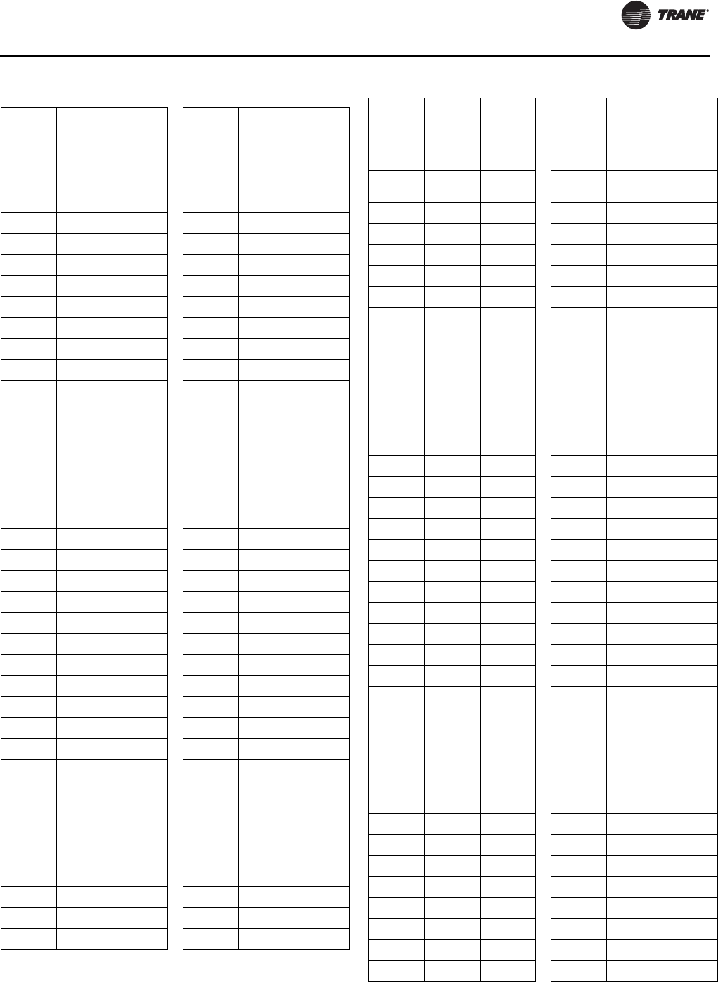
Startup
RT-SVX34H-EN 49
Table 27. Design minimum OA flow setpoint
Design
Min OA
Flow
Setpoint
(R130)
DCV Min
OA Flow
Setpoint
(R41) Voltage
Reading
Design
Min OA
Flow
Setpoint
(R130)
DCV Min
OA Flow
Setpoint
(R41) Voltage
Reading
Airflow
CFM Airflow
CFM Voltage
Vdc Airflow
CFM Airflow
CFM Voltage
Vdc
1000 1000 0.20 4500 4500 0.90
1100 1100 0.22 4600 4600 0.92
1200 1200 0.24 4700 4700 0.94
1300 1300 0.26 4800 4800 0.96
1400 1400 0.28 4900 4900 0.98
1500 1500 0.30 5000 5000 1.00
1600 1600 0.32 5100 5100 1.01
1700 1700 0.34 5200 5200 1.02
1800 1800 0.36 5300 5300 1.03
1900 1900 0.38 5400 5400 1.04
2000 2000 0.40 5500 5500 1.05
2100 2100 0.42 5600 5600 1.06
2200 2200 0.44 5700 5700 1.07
2300 2300 0.46 5800 5800 1.08
2400 2400 0.48 5900 5900 1.09
2500 2500 0.50 6000 6000 1.10
2600 2600 0.52 6100 6100 1.11
2700 2700 0.54 6200 6200 1.12
2800 2800 0.56 6300 6300 1.13
2900 2900 0.58 6400 6400 1.15
3000 3000 0.60 6500 6500 1.17
3100 3100 0.62 6600 6600 1.18
3200 3200 0.64 6700 6700 1.19
3300 3300 0.66 6800 6800 1.20
3400 3400 0.68 6900 6900 1.22
3500 3500 0.70 7000 7000 1.23
3600 3600 0.72 7100 7100 1.24
3700 3700 0.74 7200 7200 1.25
3800 3800 0.76 7300 7300 1.26
3900 3900 0.78 7400 7400 1.27
4000 4000 0.80 7500 7500 1.28
4100 4100 0.82 7600 7600 1.29
4200 4200 0.84 7700 7700 1.30
4300 4300 0.86 7800 7800 1.31
4400 4400 0.88 7900 7900 1.32
Design
Min OA
Flow
Setpoint
(R130)
DCV Min
OA Flow
Setpoint
(R41) Voltage
Reading
Design
Min OA
Flow
Setpoint
(R130)
DCV Min
OA Flow
Setpoint
(R41) Voltage
Reading
Airflow
CFM Airflow
CFM Voltage
Vdc Airflow
CFM Airflow
CFM Voltage
Vdc
8000 8000 1.34 11700 11700 1.78
8100 8100 1.36 11800 11800 1.79
8200 8200 1.38 11900 11900 1.80
8300 8300 1.39 12000 12000 1.81
8400 8400 1.40 12100 12100 1.82
8500 8500 1.41 12200 12200 1.83
8600 8600 1.42 12300 12300 1.84
8700 8700 1.43 12400 12400 1.85
8800 8800 1.44 12500 12500 1.86
8900 8900 1.45 12600 12600 1.87
9000 9000 1.46 12700 12700 1.88
9100 9100 1.47 12800 12800 1.89
9200 9200 1.48 12900 12900 1.89
9300 9300 1.50 13000 13000 1.89
9400 9400 1.52 13100 13100 1.90
9500 9500 1.53 13200 13200 1.91
9600 9600 1.54 13300 13300 1.92
9700 9700 1.55 13400 13400 1.93
9800 9800 1.57 13500 13500 1.94
9900 9900 1.58 13600 13600 1.95
10000 10000 1.59 13700 13700 1.96
10100 10100 1.60 13800 13800 1.97
10200 10200 1.61 13900 13900 1.98
10300 10300 1.63 14000 14000 1.99
10400 10400 1.65 14100 14100 2.00
10500 10500 1.67 14200 14200 2.01
10600 10600 1.68 14300 14300 2.02
10700 10700 1.69 14400 14400 2.03
10800 10800 1.70 14500 14500 2.04
10900 10900 1.71 14600 14600 2.05
11000 11000 1.72 14700 14700 2.06
11100 11100 1.73 14800 14800 2.07
11200 11200 1.74 14900 14900 2.08
11300 11300 1.74 15000 15000 2.09
11400 11400 1.75 15100 15100 2.10
11500 11500 1.76 15200 15200 2.11
11600 11600 1.77 15300 15300 2.12
Table 27. Design minimum OA flow setpoint
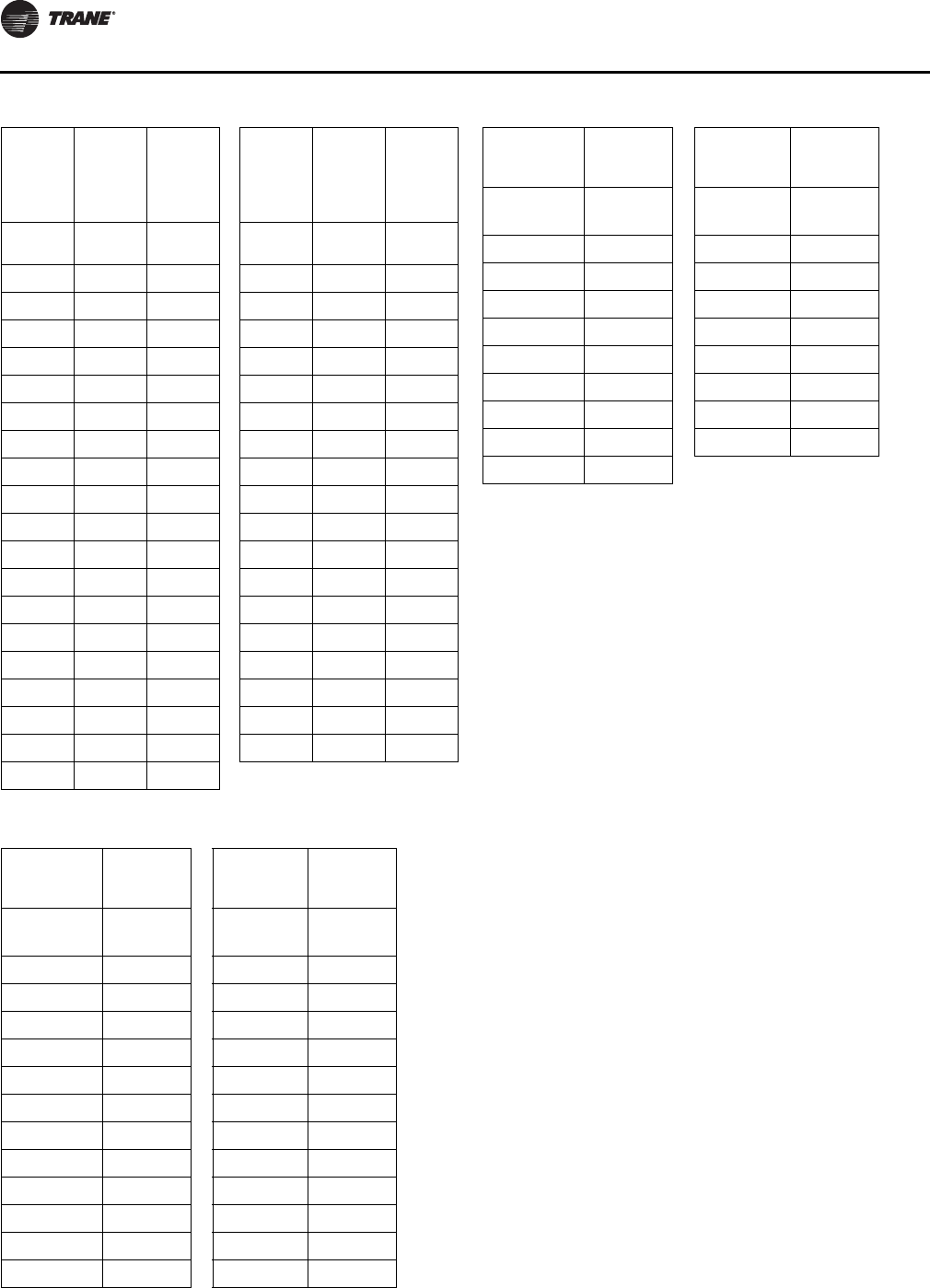
Startup
50 RT-SVX34H-EN
Ventilation Control
Units configured for Single Zone VAV control require
special handling of the OA Damper Minimum Position
control in order to compensate for the non-linearity of
airflow associated with the variable supply fan speed and
damper combinations.
Demand Controlled Ventilation
Units configured for SZVAV and Demand Controlled
Ventilation (CO2 sensor value available) require a new
control scheme comprised of 2 existing schemes that have
been traditionally mutually exclusive; DCV and OA CFM
Compensation.
Units configured with DCV will invoke the new Demand
Controlled Ventilation scheme which allows variable Bldg.
Design and DCV Minimum Positions and OA Damper
Position Target setpoints based on the supply fan speed
and space CO2 requirements.
This new scheme will require the setting of 5 OA Damper
position setpoints; 3 more than on non-SZ VAV. These new
setpoints are located on the RTVM module:
1. Design Min Position @ Minimum Fan Speed
Command (RTVM R130)
2. Design Min Position @ Middle Fan Speed Command
(RTVM R136)
3. Design Min Position @ Full Fan Speed Command
(RTEM Design Min Position)
4. DCV Min Position @ Minimum Fan Speed Command
(RTVM R41)
5. DCV Min position @ Full Fan Speed Command (RTEM
DCV Min Position)
As the supply fan speed command varies between
minimum and maximum, the Building Design and DCV
Minimum Position Targets will be calculated linearly
between the user selected setpoints based on the
Design
Min OA
Flow
Setpoint
(R130)
DCV Min
OA Flow
Setpoint
(R41) Voltage
Reading
Design
Min OA
Flow
Setpoint
(R130)
DCV Min
OA Flow
Setpoint
(R41) Voltage
Reading
Airflow
CFM Airflow
CFM Voltage
Vdc Airflow
CFM Airflow
CFM Voltage
Vdc
15400 15400 2.13 17300 17300 2.32
15500 15500 2.14 17400 17400 2.33
15600 15600 2.15 17500 17500 2.34
15700 15700 2.16 17600 17600 2.35
15800 15800 2.17 17700 17700 2.36
15900 15900 2.18 17800 17800 2.37
16000 16000 2.19 17900 17900 2.38
16100 16100 2.20 18000 18000 2.39
16200 16200 2.21 18100 18100 2.40
16300 16300 2.22 18200 18200 2.41
16400 16400 2.23 18300 18300 2.42
16500 16500 2.24 18400 18400 2.43
16600 16600 2.25 18500 18500 2.44
16700 16700 2.26 18600 18600 2.45
16800 16800 2.27 18700 18700 2.46
16900 16900 2.28 18800 18800 2.47
17000 17000 2.29 18900 18900 2.48
17100 17100 2.30 19000 19000 2.49
17200 17200 2.31
Table 28. OA flow adjustment setpoint
OA Flow
Adjustment
(R136) Voltage
Reading
OA Flow
Adjustment
(R136) Voltage
Reading
Multiplier/
Adjustment Vdc Multiplier/
Adjustment Vdc
0.80 0.00 0.92 0.88
0.81 0.05 0.93 0.94
0.82 0.14 0.94 1.00
0.83 0.22 0.95 1.06
0.84 0.30 0.96 1.10
0.85 0.35 0.97 1.18
0.86 0.43 0.98 1.22
0.87 0.51 0.99 1.25
0.88 0.57 1.00 1.3 - 1.84
0.89 0.64 1.01 1.86
0.90 0.72 1.02 1.89
0.91 0.78 1.03 1.92
Table 27. Design minimum OA flow setpoint
OA Flow
Adjustment
(R136) Voltage
Reading
OA Flow
Adjustment
(R136) Voltage
Reading
Multiplier/
Adjustment Vdc Multiplier/
Adjustment Vdc
1.04 1.96 1.13 2.20
1.05 2.00 1.14 2.24
1.06 2.03 1.15 2.26
1.07 2.06 1.16 2.28
1.08 2.10 1.17 2.30
1.09 2.12 1.18 2.34
1.10 2.14 1.19 2.36
1.11 2.16 1.20 2.40
1.12 2.18
Table 28. OA flow adjustment setpoint
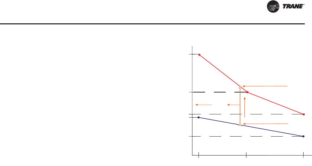
Startup
RT-SVX34H-EN 51
instantaneous supply fan speed. The Bldg. Design and
DCV Minimum Position Targets will be used to calculate
the Active OA Damper Minimum Position Target, as on
traditional units, based on the Space CO2 relative to the
active Design and DCV CO2 setpoints. Refer to Figure 40,
p. 51 for additional details on the design.
The Design Minimum and DCV Minimum OA Damper
Position setpoints at Minimum Fan Speed Command and
the Design Minimum OA Damper Position setpoint at
Middle Fan Speed Command will have a range of 0-100%
while the Design Minimum and DCV Minimum OA
Damper Position setpoints at Full fan speed will have a
range of 0-50%. Note that as on non-Single Zone VAV
units, a 10% offset will be enforced between the Design
and DCV Minimum Positions throughout the fan speed
range.
By default, the Design Minimum Position schedule (red
line below) will be a linear line through all user selectable
Design Minimum Position setpoints. The user will have the
ability to set the Design Minimum Position at Middle fan
speed command to a point that would be lower than the
calculated linear line between the Design Minimum
Position setpoints at 0% and 100% fan speed command in
order to compensate for the non-linear outside airflow
through the fan and damper modulation range. However,
if the Design Minimum Position at Middle fan speed
command is set to a point that would be higher than the
calculated linear line between the Design Minimum
Position setpoints at Minimum and Full fan speed
command, the minimum position will be limited to the
point that would make the Design Minimum Position
schedule linear.
Provisions have been made in Service Test Mode to allow
for proper damper minimum position setup:
1. To set the Design and DCV Minimum Position setpoints
at Minimum Fan Speed, set the unit to operate at Step
1 (Fan ON) or Step 2 (Economizer Open) and make the
proper adjustments.
2. To set the Design Minimum Position setpoint at Middle
Fan Speed, set the unit to operate at Step 3 (Cool 1) and
make the proper adjustment.
3. To set the Design and DCV Minimum Position setpoints
at Full Fan Speed, set the unit to operate at Step 4 (Cool
2) and make the proper adjustments.
Units with Traq Sensor
The outside air enters the unit through the Traq Sensor
assembly and is measured by velocity pressure flow rings.
The velocity pressure flow rings are connected to a
pressure transducer/solenoid assembly.The solenoid is
used for calibration purposes to compensate for
temperature swings that could affect the transducer.The
ReliaTel Ventilation Module (RTVM) utilizes the velocity
pressure input, the outdoor air temperature input, and the
minimum outside air CFM setpoint to modify the volume
(CFM) of outside air entering the unit as the measured
airflow deviates from setpoint.
For units with Traq, when the optional CO2 sensor is
installed and Demand Controlled Ventilation is enabled
the Minimum Outside Air CFM Setpoint will be adjusted
linearly between two airflow setpoints, the Design
Minimum Outside Air (OA) CFM Setpoint (R130) and the
DCV Minimum Outside Air CFM (OA) Setpoint (R41). The
resulting calculated setpoint is the Minimum OA CFM
Target which is the setpoint used for active airflow control.
The Minimum OA CFM Target Setpoint will vary
proportionally between the DCV Minimum OA Flow CFM
Setpoint and the Design Minimum OA CFM Setpoint as
CO2 varies between the CO2 Lower Limit Setpoint and the
CO2 Upper Limit Setpoint as shown in Figure 41. The CO2
setpoints are set on the RTEM as with normal DCV control
without Traq option.
Figure 40. SZVAV DCV with OA CFM compensation
Full Fan Speed
Minimum Fan Speed
Design @ Middle Fan Speed
Middle
Fan Speed
OAD
Posion
Setpoints
Corresponds to Design
CO2 (DCV UL) Setpoint
Corresponds to DCV CO2 (DCV
LL) Setpoint
OAD Target
Setpoint Increasing CO2
Design @ Minimum Fan Speed
Design @ Full Fan Speed
DCV @ Minimum Fan Speed
DCV @ Full Fan Speed
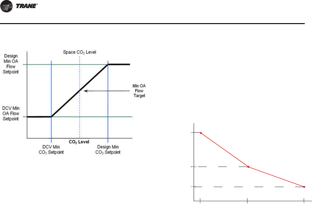
Startup
52 RT-SVX34H-EN
Outside Air Damper Minimum Positions
without DCV
For units not configured with DCV (no CO2 sensor value
available), additional minimum position setpoints to
increase outdoor airflow accuracy will be supported. The
operation will be similar to OA CFM Compensation on
Traditional VAV units with the addition of a Design
Minimum Position setpoint at Middle Fan Speed
Command. The following setpoint potentiometers will be
used on the RTEM:
1. Design Min at Minimum Fan Speed Command (RTEM
DCV Min)
2. Design Min at Middle Fan Speed Command (RTEM
DCV Setpoint LL)
3. Design Min at Full Fan Speed Command (RTEM Design
Min)
The controller will calculate the active OA Damper
Minimum position linearly between the user-selected
setpoints based on the supply fan speed command. The
range for the Design Min setpoints at Minimum and
Middle Fan Speed Command will be 0-100% while the
range for the Design Min at Full Fan Speed Command
setpoint will be 0-50%.
By default, the Design Minimum Position schedule (red
line below) will be a linear line through all user selectable
Design Minimum Position setpoints. As with Demand
Controlled Ventilation, if the Design Minimum Position at
Middle fan speed command is set to a point that would be
higher than the calculated linear line between the Design
Minimum Position setpoints at Minimum and Maximum
fan speed command, the minimum position will be limited
to the point that would make the Design Minimum Position
schedule linear.
Provisions have been made in Service Test Mode to allow
for proper damper minimum position setup:
1. To set the Design Minimum Position setpoint at
Minimum Fan Speed, set the unit to operate at Step 1
(Fan ON) or Step 2 (Economizer Open) and make the
proper adjustment.
2. To set the Design Minimum Position setpoint at Middle
Fan Speed, set the unit to operate at Step 3 (Cool 1) and
make the proper adjustment.
3. To set the Design Minimum Position setpoint at Full
Fan Speed, set the unit to operate at Step 4 (Cool 2) and
make the proper adjustment.
Space Pressure Control
For units configured with an exhaust fan, with or without
Statitrac, the control described previously for economizer
minimum position handling requires additional changes
to the existing Space Pressure Control scheme. The overall
scheme will remain very similar to non-Single Zone VAV
units with Space Pressure Control with the exception of a
dynamic Exhaust Enable Setpoint.
For Single Zone VAV the user will select an Exhaust Enable
Setpoint during the Maximum Fan Speed Command.
Once selected, the difference between the Exhaust Enable
Setpoint and Design OA Damper Minimum Position at
Maximum Fan Speed Command will be calculated. The
difference calculated will be used as an offset to be added
to the Active Building Design OA Minimum Position Target
to calculate the dynamic Exhaust Enable Target to be used
throughout the Supply Fan Speed/OA Damper Position
range.
The Exhaust Enable Target could be above or below the
Active Bldg Design OA Min Position Target Setpoint based
on the Active Exhaust Enable Setpoint being set above or
below the Bldg Design Min Position at Full Fan Speed
Command. Note that an Exhaust Enable Setpoint of 0%
will result in the same effect on Exhaust Fan control as on
non-Single Zone VAV applications with and without
Statitrac.
Figure 41. Minimum outside air CFM setpoint
Figure 42. SZVAV OA damper min position w/ OA CFM
compensation
Minimum Fan
Speed
Middle Fan
Speed
Maximum F
Speed
Design @ Minimum
Fan Speed
OAD
Position
Setpoints
Design @ Middle
Fan Speed
Design @ Maximum
Fan Speed
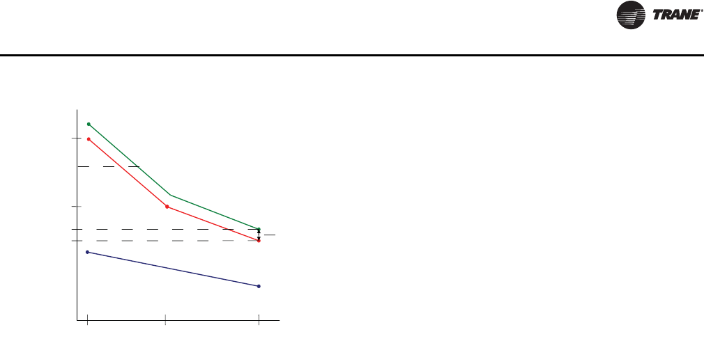
Startup
RT-SVX34H-EN 53
Traq Overrides and Special
Considerations
Traq functionality is not used in unoccupied mode since
fresh air control is an occupied ventilation function.
Damper position will be set to 0% minimum in Unoccupied
as with other types of unit configuration.
If the Remote Minimum Position pot on the RTEM is
shorted (as with NOVAR controls) the Traq minimum
damper position will be overridden to 0% as with other
unit configurations.
Traq functions and sensor value are only valid during
active Supply Fan operation therefore a value of "0 CFM"
will be substituted for any low level (bleed through) sensor
value that may be sensed on the OA Flow Sensor during
"Fan OFF" periods. OA Damper Minimum Position is only
valid during active fan operation in all configurations.
The Design Min OA Flow Setpoint will be limited to a lower
limit of 1,000 CFM and an upper limit of 20,000 CFM.
Setting of values outside of this range, except for "0 CFM",
will result in the setting being clamped within the range. A
value of "0" CFM will be allowed and will result in
initialization of the Traq OA Damper Min Position
calculation, and an active value of “0%” will be sent as the
Active Traq setpoint. This allows the user to set the damper
closed by setting the flow setpoint to 0 CFM.
If Demand Controlled Ventilation is configured then the
lower limit of the Design Min OA Flow Setpoint will be
1,500 CFM to allow a gap to the DCV Min OA Flow Setpoint
of 500 CFM making its lower limit 1,000 CFM. When the
Design Min OA Flow Setpoint is greater than 1,500 CFM a
minimum of 500 CFM offset will be enforced between the
DCV Min OA Flow Setpoint and the Design Min OA Flow
Setpoint.
If configured for Traq operation and OA CFM
Compensation, the unit will perform Traq control since it
will be the most accurate method of control. This situation
might occur if a unit is upgraded to Traq control, but the OA
CFM Compensation config jumper on the RTEM is left on.
It will be assumed by the presence of a valid OA CFM Flow
Sensor and the RTVM version that supports Traq is
accompanied by all the necessary unit equipment
upgrades.
Supply Air Temperature Control - Heating
and Cooling
For Cooling, Heating (Modulating Heat Only), and
Dehumidification operation the unit will control the active
capacity outputs to meet a varying, calculated Discharge
Air Setpoint that is calculated based on zone conditions in
order to maintain the Zone Temperature to the active Zone
Setpoint. Note that this setpoint will be clamped between
the user selected DA Heat and DA Cool - Fan Speed
setpoints that are set on the RTOM for compressor and
economizer control. In general, as the zone temperature
rises above the ZCSP, the Active Discharge Air Setpoint will
be calculated down and as the zone temperature falls
below the ZHSP Tset will be calculated upward. This
calculated setpoint is a direct indication of space demand
and is also used to determine the proper supply fan speed
to meet the space requirements. During active capacity
control, the unit will utilize a +/- 3.5°F deadband around the
active Discharge Air Setpoint to determine when to
request additional heating or cooling capacity similarly to
traditional VAV control, as described below. If the unit is
maintaining the discharge air temperature within the +/-
3.5°F deadband around the calculated discharge air
setpoint requirements, no additional capacity will be
requested.
The calculated setpoint will also be used for active
economizer control, but the economizer will utilize a
tighter control deadband (+/- 1.5°F) than that is used for
compressor output control. Also, as on Traditional VAV
units, mechanical cooling will be inhibited if economizing
is enabled until the economizer has been full open for 3
minutes.
Variable Air Volume Applications
(Traditional VAV)
Supply Air Temperature Control -
Occupied Cooling and Heating
The RTRM is designed to maintain a selectable supply air
temperature of 40°F to 90°F with a +/- 3.5°F deadband. In
cooling, if supply air temperature is more than 3.5 degrees
warmer than the selected temperature, a stage of cooling
will be turned “On” (if available). Then if the supply air
temperature is more than 3.5 degrees cooler than the
selected temperature, a stage of cooling will be turned
“Off”.
At very low airflows the unit may cycle stages “On” and
“Off” to maintain an average discharge air temperature
outside the 7 degree deadband.
Figure 43. Space pressure control graph
OAD
Position
Setpoints
Exhaust Enable Target
Exhaust Enable @
Maximum Fan Speed
Exhaust Enable @
Maximum Fan Speed
Design @ Maximum
Fan Speed
Minimum Fan Speed Maximum Fan SpeedMiddle Fan Speed
Fan Speed Algorithm Command
Exhaust Enable
Oset

Startup
54 RT-SVX34H-EN
If the unit has modulating heat, the unit can be made to do
discharge heating with VAV control. This is done by
placing a contact closure across the “Changeover Input”
on the RTAM. During this mode, the unit will heat to the
Supply Air Heating Setpoint +/- 3.5°F. During low load or
low airflow conditions the actual temperature swing of the
discharge air will likely be greater.
The RTRM utilizes a proportional and integral control
scheme with the integration occurring when the supply air
temperature is outside the deadband. As long as the
supply air temperature is within the setpoint deadband,
the system is considered to be satisfied and no staging up
or down will occur.
Supply Air Temperature Control with an
Economizer
The economizer is utilized to control the supply air cooling
at +1.5°F around the supply air temperature setpoint range
of 40°F and 90°F providing the outside air conditions are
suitable.
While economizing, the mechanical cooling is disabled
until the economizer dampers have been fully open for
three minutes. If the economizer is disabled due to
unsuitable conditions, the mechanical cooling will cycle as
though the unit had no economizer.
VHR Relay Output
During unoccupied mode, daytime warm-up (DWU) and
morning warm-up (MWU) the VFD will open to 100%. All
VAV boxes must be opened through an ICS program or by
the VHR wired to the VAV boxes. The RTRM will delay
100% fan operation approximately 6.5 minutes when
switching from occupied cooling mode to a heating mode.
Zone Temperature Control without a
Night Setback Panel or ICS - Unoccupied
Cooling
When a field supplied occupied/unoccupied switching
device is connected between RTRM J6-11 and RTRM J6-12,
both the economizer and the mechanical cooling will be
disabled.
Zone Temperature Control without a
Night Setback Panel or ICS - Unoccupied
Heating
When a field supplied occupied/unoccupied switching
device is connected between RTRM J6-11 and J6-12 and
DWU is enabled, the zone temperature will be controlled at
10°F below the Morning Warm-up setpoint, but not less
than 50°F, by cycling one or two stages of either gas or
electric heat, whichever is applicable.
Morning Warm-up (MWU) Control
Morning Warm-up is activated if the zone temperature is at
least 1.5°F below the MWU setpoint whenever the system
switches from Unoccupied to Occupied status. The MWU
setpoint may be set from the unit mounted potentiometer
or a remotely mounted potentiometer. The setpoint
ranges are from 50°F to 90°F. When the zone temperature
meets or exceeds the MWU setpoint, the unit will switch to
the “Cooling” mode. The economizer will be held closed
during the morning warm-up cycle.
Daytime Warm-up (DWU) Control
Daytime Warm-up is applicable during occupied status
and when the zone temperature is below the initiation
temperature. It can be activated or deactivated through
ICS or a night setback zone sensor. If ICS or a night setback
zone sensor is not utilized, DWU can be activated by
setting the DWU enable DIP switch (RTAM) to ON and
supplying a valid morning warm-up setpoint.
The unit is shipped with a Morning Warm-up setpoint
configured and the Daytime Warm-up function is activated
(switch on). Opening the DWU enable switch will disable
this function.
If the system control is local, the DWU initiation setpoint is
3°F below the Morning Warm-up setpoint. The termination
setpoint is equal to the Morning Warm-up setpoint.
If the system control is remote (Tracer™), the DWU
setpoint is equal to the Tracer Occupied heating setpoint.
The initiation and termination setpoints are selectable
setpoints designated by Tracer.
When the zone temperature meets or exceeds the
termination setpoint while the unit is in an Occupied,
“Auto” Mode or switched to the “Cooling” Mode, the unit
will revert to the cooling operation.
If an Occupied “Heating” Mode is selected, the unit will
only function within the DWU perimeters until the system
is switched from the “Heat” Mode or enters an
Unoccupied status.
Note: When a LCI is installed on a VAV unit, the MWU
setpoint located on the RTAM board is ignored. The
MWU and DWU setpoints come from the higher
priority LCI-R DAC.
Supply Duct Static Pressure Control
The supply duct static pressure is measured by a
transducer with a 0.25 to 2.125 Vdc proportional output
which corresponds to an adjustable supply duct static
pressure of 0.3" w.c. to 2.5" w.c. respectively with a
deadband adjustment range from 0.2" w.c. to 1.0" w.c. The
setpoint is adjustable on the RTAM Static Pressure
Setpoint potentiometer or through ICS.
Example:
Supply Duct Static setpoint = 2.0" w.c. (RTAM)
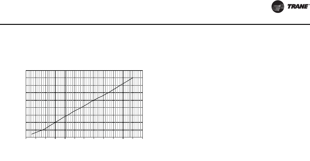
Startup
RT-SVX34H-EN 55
Deadband = 0.2" w.c. (RTAM)
Duct Static Control Range = 1.9" w.c. to 2.1" w.c.
Supply Air Temperature Reset
The supply air temperature can be reset by using one of
four DIP switch configurations on the RTAM or through ICS
when a valid supply air reset setpoint with a supply air
reset amount is given. A selectable reset amount of 0° F to
20°F via RTAM potentiometer or ICS is permissible for each
type of reset.
The amount of change applied to the supply air
temperature setpoint depends on how far the return air,
zone, or outdoor air temperature falls below the reset
temperature setpoint. If the return air, zone, or outdoor air
temperature is equal to or greater than the reset
temperature setpoint, the amount of change is zero.
If the return air, or zone temperature falls 3°F below the
reset temperature setpoint, the amount of reset applied to
the supply air temperature will equal the maximum
amount of reset selected.
If the outdoor air temperature falls 20°F below the reset
temperature setpoint, the amount of reset applied to the
supply air temperature will equal the maximum amount of
reset selected. The four DIP switch configurations are as
follows:
1. None - When RTAM DIP Switch #3 and #4 are in the
“Off” position, no reset will be allowed.
2. Reset based on Return Air Temperature - When RTAM
DIP Switch #3 is “Off” and Switch #4 is “On”, a
selectable supply air reset setpoint of 50°F to 90°F via
a unit mounted potentiometer or Tracer™ is
permissible.
3. Reset based on Zone Temperature - When RTAM DIP
Switch #3 is “On” and Switch #4 is “Off”, a selectable
supply air reset setpoint of 50°F to 90°F via RTAM
potentiometer or Tracer is permissible.
4. Reset based on Outdoor Air Temperature - When DIP
Switch #3 and #4 are “On”, a selectable supply air reset
setpoint of 0°F to 100°F via RTAM potentiometer or
Tracer is permissible.
VAV Supply Air Tempering (Only Available
with Modulating Gas Heat)
The gas heater will be modulated to prevent the Discharge
Air Temperature from falling below the Discharge
Temperature Deadband. Upon satisfying the Supply Air
Tempering requirements, a 5 minute SA Tempering Delay
timer will start whenever the modulating gas heat
combustion blower is commanded to 0 and must time out
before the unit will be allowed to re-enter “Cool” mode.
This timer will be reset to 5 minutes whenever there is an
active call for “Supply Air Tempering”. Tempering will be
discontinued whenever;
a. The 5 minutes “Supply Air Tempering Delay” timer
has timed-out and;
b. There is an active cooling request for VAV Occupied
Cooling.
Constant Volume or Variable Air
Volume Applications (Single Zone
or Traditional)
Off Mode
This mode is set at the zone sensor or by ICS. During this
status, no heating, ventilation, or mechanical cooling is
being performed. When switching the “System” selector
to the “Off” mode from any other mode, any diagnostic
data and diagnostic indication signal will be retained as
long as the system remains in the “Off” status. Switching
the “System” selector from the “Off” mode back to any
other mode of operation will reset all diagnostics.
Zone Temperature - Unoccupied Cooling
(CV or SZ VAV Only)
While a building is in an unoccupied period as designated
by a remote panel with night setback, ICS or RTRM J6-11
and J6-12, the necessary cooling capacity will be
controlled to maintain the zone temperature to within the
unoccupied setpoint deadband. If an economizer is
enabled, it will modulate in an attempt to maintain the
zone temperature to within the setpoint deadband.
Note: On SZ VAV units, the Supply Air Fan Speed will be
controlled as during normal occupied conditions in
order to meet the requirements of the zone.
Unoccupied mode does not require full airflow on
a SZ VAV unit during Cooling operation.
Zone Temperature - Unoccupied Heating
While a building is in an unoccupied period as designated
by a remote panel with night setback or ICS, the necessary
heating capacity will be controlled to maintain the zone
temperature to within the unoccupied setpoint deadband.
Figure 44. Output vs. input
Transducer Voltage Output vs Pressure Input
0.0
0.5
1.0
1.5
2.0
2.5
3.0
3.5
4.0
4.5
-0.5 0.0 0.5 1.0 1.5 2.0 2.5 3.0 3.5 4.0 4.5 5.0 5.5
Pressure (inches w.c.)
Volts
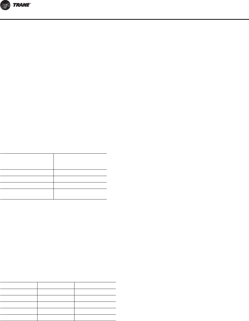
Startup
56 RT-SVX34H-EN
For traditional VAV systems, the VFD will operate at 100%
during this mode. It will be necessary to drive VAV boxes
to their maximum position through ICS programming or
the factory provided VHR relay. For SZ VAV systems, the
Supply Air Fan VFD will remain in control as during normal
occupied periods and will be controlled in order to meet
the space requirements. The minimum fan speed will be
based on the configured unit heating type. For Modulating
Heat units, Full Airflow is not required for SZ VAV
applications during Unoccupied periods. For all Staged
Heating types, the Supply Fan will be controlled at
maximum fan speed during active heating operation as
during Occupied periods.
Mechanical Cooling with an Economizer
The economizer is utilized to control the zone temperature
when the outside air conditions are suitable. The method
used to determine economizer effectiveness, depending
on the available data, is described below in descending
order of complexity. The most sophisticated method
available is always used.
Two of the three methods for determining the suitability of
the outside air can be selected utilizing the potentiometer
on the Economizer Actuator, as described below:
1. Ambient Temperature - controlling the economizing
cycle by sensing the outside air dry bulb temperature.
Table 30 lists the selectable dry bulb values by
potentiometer setting.
2. Reference Enthalpy - controlling the economizer cycle
by sensing the outdoor air humidity. Table 30 lists the
selectable enthalpy values by potentiometer setting. If
the outside air enthalpy value is less than the selected
value, the economizer is allowed to operate.
3. Comparative Enthalpy - By utilizing a humidity sensor
and a temperature sensor in both the return air stream
and the outdoor air stream, the economizer will be able
to establish which conditions are best suited for
maintaining the zone temperature, i.e., indoor
conditions or outdoor conditions.
Gas Heat Control
The ignition sequence and timing are provided by a
separate heat control module. The RTRM only provides
the heating outputs to initiate 1st and 2nd stages and
control the combustion blower relays. Both stages of the
furnace, when initiated after each cycle, will start and
operate for one minute then cycle back if only one stage is
required. Units with modulating heat capabilities will light
on high fire for one minute and then modulate to the
appropriate heating rate for the building load present.
When the fan selection switch is in the “AUTO” mode and
the unit is configured as a Constant Volume with staged or
modulating gas heat, or SZ VAV with staged gas heat, the
fan will be delayed from coming on for approximately 30
seconds after a call for heat has been initiated. The fan will
remain on for approximately 90 seconds after the heating
setpoint has been satisfied. If the unit is configured for SZ
VAV with modulating heat, the fan will be energized with
the call for heating in order to begin circulating airflow
through the unit for discharge air temperature control.
Once the call for heating is removed, the fan will remain on
for approximately 90 seconds.
Electric Heat Control
The RTRM provides two heating outputs for 1st and 2nd
stages that will be controlled with at least a 10 seconds
delay between each stage. When the fan selection switch
is in the “AUTO” mode and the unit is configured for
Constant Volume, the fan will start approximately 1
second before the 1st heater stage is activated. The fan and
heater will cycle off after the heating setpoint has been
satisfied. If the unit is configured for SZ VAV control, the
Supply Fan will energize approximately 5 seconds prior to
energizing the electric heat outputs. Once the Zone
Heating requirements have been satisfied, the fan and
heat outputs will be controlled off.
Clogged Filter Option
The unit mounted clogged filter switch monitors the
pressure differential across the return air filters. It is
mounted in the filter section and is connected to the
RTOM. The switch is adjustable and can be set for a
particular application. The clogged filter switch is normally
open and will automatically close when the pressure
differential across the filters falls below the clogged filter
setpoint. The RTOM will generate a SERVICE diagnostic
that will be sent to the zone sensor or remote panel when
the clogged filter switch has been closed for at least 2
minutes during supply fan operation. The system will
continue to operate regardless of the status of the clogged
filter switch.
Table 29. Economizer effectiveness
Method used to
determine economizer
effectiveness Required
Comparative Enthalpy OAT, OAH, RAT, RAH
Reference Enthalpy OAT, OAH
Reference Dry Bulb OAT
Unable to determine
effectiveness OAT data is invalid or
unavailable
Table 30. Economizer configuration
Selection Dry Bulb Enthalpy Value
A73°F 27 BTU/LB Air
B70°F 25 BTU/LB Air
C67°F 23 BTU/LB Air
D63°F 22 BTU/LB Air
E55°F 19 BTU/LB Air
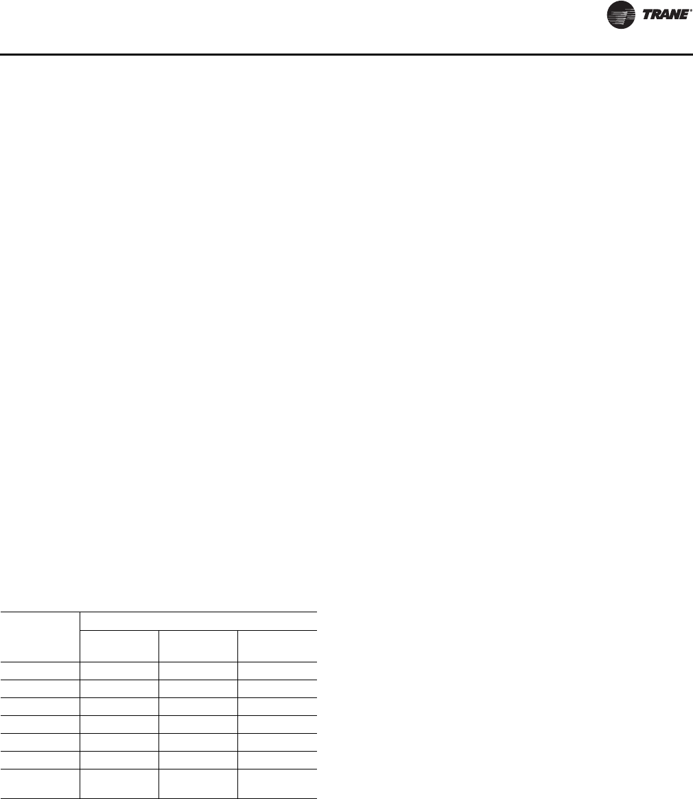
Startup
RT-SVX34H-EN 57
Ventilation Override
Note: Applying 24 volts to one of the three Ventilation
Override Inputs manually activates ventilation
override. One input is provided to request the
Pressurize Mode, the second input the Purge Mode,
and the third input the Exhaust Mode.
When the Pressurize Mode is selected, activating
Ventilation Override will cause the supply fan to run, the
economizer to open to 100%, the exhaust fan to turn
(remain) off, or the VFD to run at full speed (SZ VAV and
Traditional VAV), and the VAV boxes to fully open.
When Purge is selected, activating Ventilation Override
will cause the supply fan to run, the economizer to open to
100%, the exhaust fan to run, or the VFD to run at full speed
(SZ VAV or Traditional VAV), and the VAV boxes to fully
open.
When Exhaust is selected, activating Ventilation Override
will cause the supply fan to turn off, the economizer to
close to 0%, the exhaust fan to run (exhaust damper at
100% if configured for Statitrac), or the VFD to stop, and
the VAV boxes to operate normally.
If more than one mode is requested at the same time, the
Pressurize request will have priority followed by Purge.
When any Ventilation Override Mode is active, all heating
and cooling is turned off. For the case where the unit is
required to turn off, the Emergency Stop input is used. The
ICS can also initiate any ventilation override mode.
Table 31 lists the sequence of events within the system for
each ventilation mode. Refer to the unit wiring diagram for
contact switching and wiring.
Note: Fresh air tracking will not work with VOM.
Emergency Stop
When this binary input is opened, all outputs are
immediately turned off and the system will not be allowed
to restart until the binary input is closed for approximately
5 seconds minimum. The shut down is communicated to
Tracer™ if applicable and the Heat and Cool LED outputs
(RTRM J6-7 and J6-8) will blink at a nominal rate of 1 blink
per second.
Phase Monitor
The Phase Monitor is a 3 phase line monitor module that
protects against phase loss, phase reversal and phase
unbalance. It is intended to protect compressors from
reverse rotation. It has an operating input voltage range of
190-600 VAC, and LED indicators for ON and FAULT. There
are no field adjustments and the module will automatically
reset from a fault condition.
Low Pressure Control
This input incorporates the low pressure cutout of each
refrigeration circuit and can be activated by opening a field
supplied contact.
If this circuit is open before a compressor(s) is started,
neither compressor in that circuit will be allowed to
operate.
Anytime this circuit is opened for 5 continuous seconds,
the compressor(s) in that circuit are turned off
immediately. The compressor(s) will not be allowed to
restart for a minimum of 3 minutes.
If four consecutive open conditions occur during the first
three minutes of operation, the compressor(s) in that
circuit will be locked out, a diagnostic communicated to
Tracer, and a manual reset will be required to restart the
compressor(s).
The dehumidification option has one reheat low pressure
cutout (RLP). The RLP is located on the reheat circuit.
Dehumidification Low Pressure Control
The RLP has been added to insure proper refrigerant
management during active modulating hot gas reheat
operation.
The RLP will be ignored for the first 10 minutes of
compressor run time during active hot gas reheat
operation. Anytime this circuit is opened for 5 continuous
seconds, the compressor(s) in that circuit are turned off
immediately. The compressor(s) will not be allowed to
restart for a minimum of 3 minutes. If four consecutive
open conditions occur during active dehumidification, the
compressor(s) in that circuit will be locked out.
High Pressure Cutout and Temperature
Discharge Limit
The high pressure controls and temperature discharge
limit are wired in series between the compressor outputs
on the RTRM and the compressor contactors. On 27.5, 30,
and 35 Ton units, if the high pressure safety switch or
temperature discharge limit opens, the RTRM senses a lack
of current while calling for cooling and locks both
compressors out with an auto reset. On 40 and 50 Ton
units, if the high pressure safety or temperature discharge
Table 31. Ventilation override sequence
Mode and Priority
Affected
Function Pressurize Purge Exhaust(a)
(a)Exhaust mode 3 is not available with the tracking power exhaust
option.
123
Heat/Cool off off off
VFD full speed full speed full speed
Supply Fan on on off
Exhaust Fan off on(b)
(b)For units configured with the Statitrac option, the Exhaust Damper
will open during Ventilation Override modes that request the ex-
haust fan to operate.
on
Economizer open open closed
VAV Boxes forced open forced open normal
operation
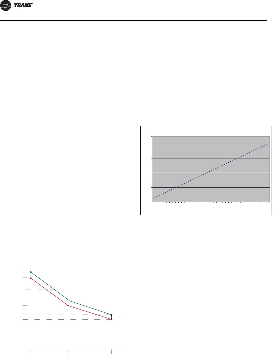
Startup
58 RT-SVX34H-EN
limit opens, the compressor(s) on the affected circuit is
locked out. If the compressor output circuit is opened four
consecutive times during compressor operation, the
RTRM will generate a manual reset lockout.
Power Exhaust Control (Standard)
The power exhaust fan is started whenever the position of
the economizer dampers meets or exceed the power
exhaust setpoint when the supply fan is on.
The setpoint potentiometer is on the RTOM and is factory
set at 25% for traditional constant volume and variable air
volume units.
For SZ VAV units the default power exhaust enable
setpoint will be 25% as on non-SZ VAV units. However, for
SZ VAV the Exhaust Enable Setpoint will need to be
adjusted for the proper setpoint during the maximum Fan
Speed Command for the unit. Once selected, the
difference between the Exhaust Enable Setpoint and
Design OA Damper Minimum Position at Full Fan Speed
Command will be calculated. The difference calculated will
be used as an offset to be added to the Active Building
Design OA Minimum Position Target to calculate the
dynamic Exhaust Enable Target to be used throughout the
Supply Fan Speed/OA Damper Position range:
Exhaust Enable Target = Active Bldg Design OA Min
Position Target + (Active Exhaust Enable Setpoint – Active
Bldg Design OA Min Position @ Full Fan Speed Command)
The Exhaust Enable Target could be above or below the
Active Bldg Design OA Min Position Target Setpoint based
on the Active Exhaust Enable Setpoint being set above or
below the Bldg Design Min Position at Full Fan Speed
Command. Note that an Exhaust Enable Setpoint of 0%
will result in the same effect on Exhaust Fan control as on
non-Single Zone VAV applications with and without
Statitrac; Exhaust Fan ON. See Figure 45, p. 58 for how the
exhaust enable setpoint is modified throughout the OA
damper operating range.
Space Pressure Control - Statitrac
A pressure transducer is used to measure and report direct
space (building) static pressure. The user-defined control
parameters used in this control scheme are Space
Pressure Setpoint and Space Pressure Deadband. As the
Economizer opens, the building pressure rises and
enables the Exhaust Fan. The Exhaust dampers will be
modulated to maintain Space Pressure within the Space
Pressure Deadband.
Note: The Exhaust Enable setpoint will need to be
selected as on units with standard power exhaust
control.
Power Exhaust Control (Tracking)
The power exhaust dampers proportionally track or follow
the fresh air (economizer) damper position. The offset
between the fresh air and the exhaust damper(s) is
adjustable, see figures beginning with Figure 53, p. 76.
Refer to Power Exhaust Fan Performance” tables
beginning with Table 50, p. 76.
Lead/Lag Control
Lead/Lag is a selectable input located on the RTRM. On 2
& 3 stage standard efficiency units, the RTRM is configured
from the factory with the Lead/Lag control disabled. To
activate the Lead/Lag function, simply remove the jumper
connection J3-8 at the RTRM Lead/Lag input. When it is
activated, each time the designated lead compressor(s) is
shut off due to the load being satisfied, the lead
compressor or refrigeration circuit switches. On the 5
stage high efficiency units, the RTRM is configured from
the factory with the Lead/Lag control enabled. With it
active, each time the designated lead compressor is shut
off due to the load being satisfied, the controls will switch
to the next staging sequence. When the RTRM is powered
up, i.e. after a power failure, the control will default to the
number one compressor.
Figure 45. SZ VAV exhaust
Maximum Fan Speed Minimum Fan Speed Middle Fan Speed
OAD
Posion
Setpoints
Design @ Full Fan Speed
Exhaust Enable
Offset
Exhaust Enable @ Full
Fan Speed
Exhaust Enable Target
Figure 46. Transducer voltage output vs. pressure input for
building pressure
-0.75 to 9.0 Iwc Pressure Transducer Voltage Output vs. Pressure Input
0.00
0.50
1.00
1.50
2.00
2.50
3.00
3.50
4.00
4.50
-0.75
-0.25
0.25
0.75
1.25
1.75
2.25
2.75
3.25
3.75
4.25
4.75
5.25
5.75
6.25
6.75
7.25
7.75
8.25
8.75
Pressure (inches w.c.)
Volts
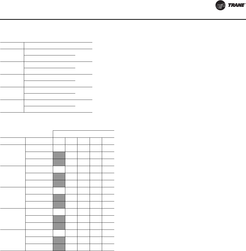
Startup
RT-SVX34H-EN 59
Coil Frost Protection
The Frostat™ control monitors the suction line
temperature to prevent the evaporator from freezing due
to low operating temperatures whenever there is a
demand for cooling. When a closed circuit has occurred for
5 seconds minimum, the RTRM turns off all of the cooling
outputs. The Supply Fan will be held “On” until the Frostat
has been open for 5 continuous seconds or for 60 seconds
after the last compressor was shut “Off”, whichever is the
longest. The compressor shutdown is communicated to
Tracer, if applicable. There is no local diagnostic for this
condition.
Dehumidification Frost Protection
Two control schemes will be active on units configured for
Dehumidification. The first employs the use of the Frostat
function. The second scheme takes precedence over
Frostat. Operation will be as described below.
The second scheme is in control during active
dehumidification or cooling and includes the use of an
Entering Evaporator Temperature sensor (EET). If the EET
drops below 35°F for 10 continuous minutes compressors
will stage off. For dual circuit units one circuit will be
staged off initially, and then if the EET remains below 35ºF
for an additional 10 minutes, the second circuit will be
staged off. For single circuit units one compressor will be
staged off initially, and then if the EET remains below 35ºF
for an additional 10 minutes, the second circuit will be
staged off. When the unit is operating in dehumidification
mode, only the reheat circuit will be re-enabled if the EET
rises above 45ºF. The cooling circuit will not be re-enabled
during dehumidification until the unit leaves the current
dehumidification cycle or a dehumidification purge is
initiated. If the unit is operating in Cooling, the first circuit
that de-energized will be re-enabled when the EET rises
above 45ºF. The second compressor will be allowed to re-
energize at 10 minutes after the EET rises above 45ºF or if
a purge cycle is initiated.
Drain Pan Condensate Overflow Switch
(Optional)
This input incorporates the Condensate Overflow Switch
(COF) mounted on the drain pan and the ReliaTel Options
Module (RTOM). When the condensate level reaches the
trip point for 6 continuous seconds, the RTOM will shut
down all unit function until the overflow condition has
cleared. The unit will return to normal operation after 6
continuous seconds with the COF in a non-tripped
condition. If the condensate level causes the unit to
shutdown more than 2 times in a 3 day period, the unit will
be locked-out of operation. A manual reset of the
diagnostic system through the Zone Sensor or Building
Automation System (BAS) will be required. Cycling unit
power will also clear the fault.
VFD Programming Parameters
See System Troubleshooting section.
Condenser Fan Sequencing Control
The condenser fans are cycled according to the outdoor air
temperature and the number of cooling steps that are
operating. Table 34 lists the temperatures at which the A
and B Condenser Fan Outputs on the RTRM switches the
fans “Off”. The fans are switched back “ON” when the
outdoor temperature rises approximately 5° F above the
“Off” temperature.
Figure 47, p. 60 shows the condenser fans as viewed from
the top of the unit facing the control panel. Whenever a
condenser fan is cycled back “On”, the condenser fan
Table 32. Capacity steps with lead/lag enabled - std
Efficiency
Unit Size Step 1 Step 2 Step 3
TC*330 LEAD 48% 100%
LAG 52% 100%
TC*360 LEAD 50% 100%
LAG 50% 100%
TC*420 LEAD 47% 100%
LAG 53% 100%
TC*480 LEAD 40% 60% 100%
LAG 60% 100%
TC*600 LEAD 32% 68% 100%
LAG 68% 100%
Table 33. Capacity staging sequence - high Efficiency
Steps
Unit SizeSequence12345
TC*330
1 25376375100
237 63 75 100
337 63 75 100
TC*360
1 24386276100
238 62 76 100
338 62 76 100
TC*420
1 22396178100
239 61 78 100
339 61 78 100
TC*480
1 23396177100
239 61 77 100
339 61 77 100
TC*600
1 25386275100
238 62 75 100
338 62 75 100
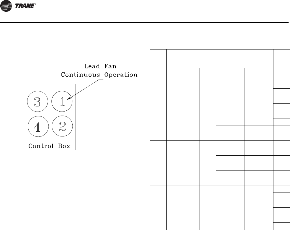
Startup
60 RT-SVX34H-EN
Outputs A and B and the compressor steps are de-
energized for approximately seven seconds to prevent
problems with fan windmill.
Figure 47. Condenser fan location
Table 34. Condenser fan/compressor sequence - std
efficiency
Unit
Size
(Ton)
Compressor Staging
Sequence Condenser Fan Output
O/A
Temp.
(°F)
Step 1 Step2 Step 3 Output A Output B Fans
“Off”
27.5 -
30
CPR
1(a)
(a) Single circuit, manifolded compressors pair.
N/A
Fan #2 70
Fan #3 90
CPR 1,
2Fan #2 -10
Fan #3 60
35
CPR
1(a) Fan #2 65
Fan #3 85
CPR 1,
2N/A Fan #2 -20
Fan #3 55
40
CPR
1(b)
(b)First Stage, Number one refrigeration circuit, Standalone compressor is
“On”.
Fan #2 50
Fan #3, 4 70
CPR
2(c)
(c) First Stage is “Off”, Number two refrigeration circuit, standalone com-
pressor is “On”.
Fan #2 20
Fan #3, 4 60
CPR 1,
2Fan #2 -30
Fan #3, 4 50
50
CPR
1(b) Fan #2 20
Fan #3, 4 60
CPR 2,
3(d)
(d)First stage is “Off”, Number two refrigeration circuit, manifolded com-
pressor pair is “On” operating simultaneously.
Fan #2 -10
Fan #3, 4 55
CPR 1,
2, 3 Fan #2 -30
Fan #3, 4 50
Notes:
1. The Compressor(s) listed under each step are the operating
compressors. On 27.5 to 35 Ton units with Lead/Lag, CPR1 will
alternate but the fan sequence will remain the same. On 40 & 50 Ton
units with Lead/Lag, the compressor(s) in step 2 & 3 will alternate and
the fan sequence listed for that step will be in operation.
2. Conventional thermostat sequence: Y1=CPR1, Y2=CPR2 (40 CPR 2 &
50 CPR 2,3), Y1 + Y2 = CPR1,2 (40 CPR 1,2 & 50 CPR 1,2,3)
3. During active dehumidification all compressors will be staged “On”.
For units equipped with four condenser fans (40 and 50 Ton), the
condenser fan output states will be controlled based on the O/A
temperature. If O/A is above 85°F, all condenser fan outputs will be
energized. If O/A falls below 80°F, Output B will de-energize and will
not re-energize again until the O/A rises above 85°F.
For units configured with three condenser fans (27.5 to 35 Ton), a
maximum of two condenser fans will energize. Output A will energize
above 85°F and de-energize when the O/A falls below 80°F; Output B
will remain de-energized during active dehumidification. If O/A falls
below 80°F, Output A will de-energize and will not re-energize again
until O/A rises above 85°F
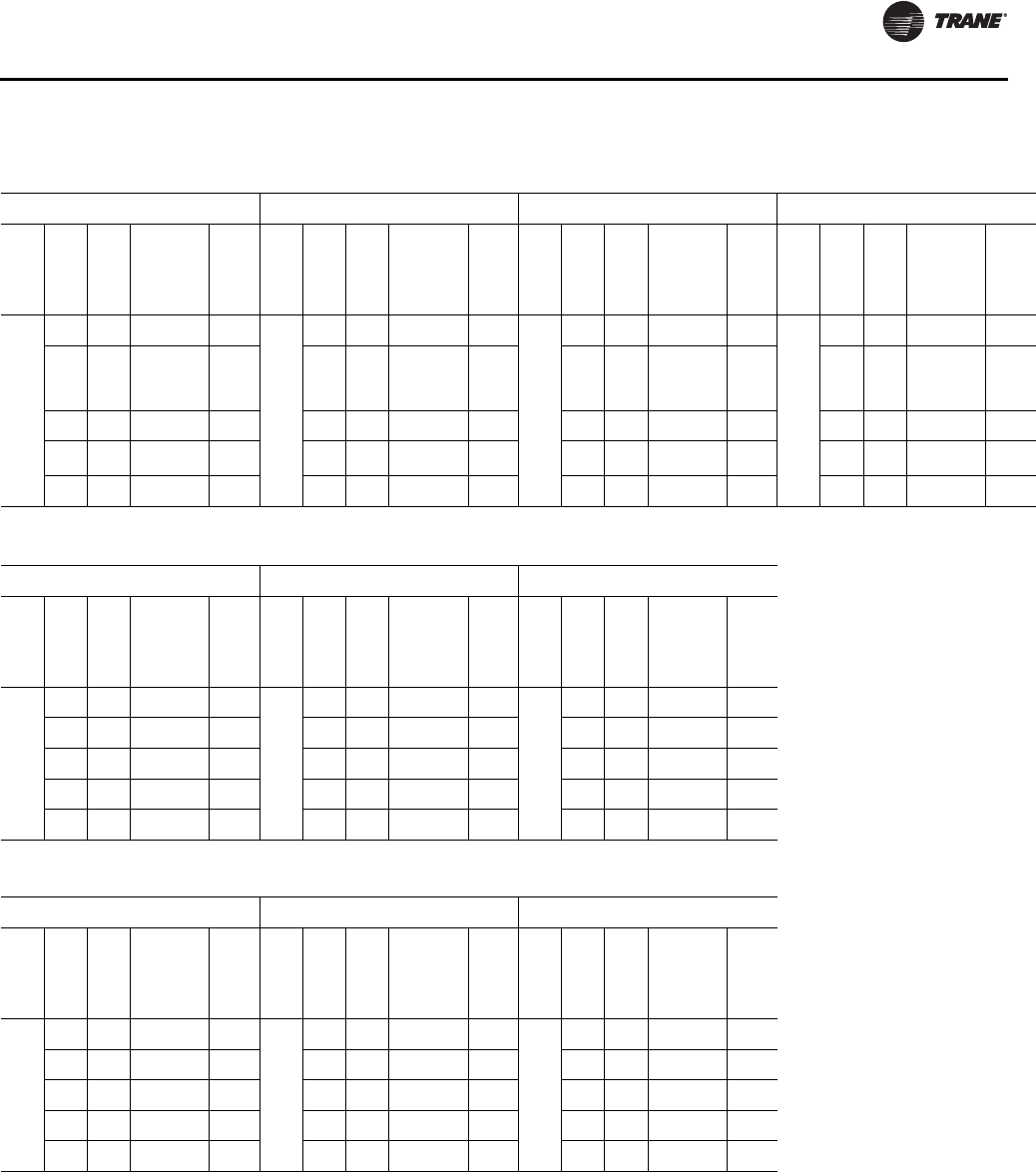
Startup
RT-SVX34H-EN 61
Table 35. Condenser fan/compressor sequence - high efficiency
27.5-35 Ton High Efficiency
Compressor Stage 1 Compressor Stage 2 Compressor Stages 3 or 4 Compressor Stage 5
Fan
#1 Fan
#2 Fan
#3
Ambient
Range
(F)
#
Cond
Fans
On Fan
#1 Fan
#2 Fan
#3
Ambient
Range
(F)
#
Cond
Fans
On Fan
#1 Fan
#2 Fan
#3
Ambient
Range
(F)
#
Cond
Fans
On Fan
#1 Fan
#2 Fan
#3
Ambient
Range
(F)
#
Cond
Fans
On
ON
OFF OFF 0-70 1
ON
OFF OFF 0-58 1
ON
OFF OFF 0-60 1
ON
OFF OFF 0-50 1
OFF1OFF 70-75 1 or 2 OFF1OFF 58-63 1 OR 2 OFF1OFF 60-65 1 OR 2 OFF1OFF 50-55 1 OR 2
ON OFF 75-80 2 ON OFF 63-70 2 ON OFF 65-70 2 ON OFF 55-60 2
ON OFF180-85 2 or 3 ON OFF170-75 2 OR 3 ON OFF170-75 2 OR 3 ON OFF160-65 2 OR 3
ON ON 85-115 3 ON ON 75-115 3 ON ON 75-115 3 ON ON 65-115 3
40 Ton High Efficiency
Compressor Stages 1&2 Compressor Stages 3&4 Compressor Stage5
Fan
#1 Fan
#2
Fan
#3&
4
Ambient
Range
(F)
#
Cond
Fans
On Fan
#1 Fan
#2
Fan
#3&
4
Ambient
Range
(F)
#
Cond
Fans
On Fan
#1 Fan
#2
Fan
#3&
4
Ambient
Range
(F)
#
Cond
Fans
On
ON
OFF OFF 0-65 1
ON
OFF OFF 0-60 1
ON
OFF OFF 0-40 1
OFF1OFF 65-70 1 or 2 OFF1OFF 60-65 1 OR 2 OFF1OFF 40-45 1 OR 2
ON OFF 70-80 2 ON OFF 65-75 2 ON OFF 45-65 2
ON OFF180-85 2 or 4 ON OFF175-80 2 OR 4 ON OFF165-70 2 OR 4
ON ON 85-115 4 ON ON 80-115 4 ON ON 70-115 4
50 Ton High Efficiency
Compressor Stages 1&2 Compressor Stages 3&4 Compressor Stage5
Fan
#1 Fan
#2
Fan
#3&
4
Ambient
Range
(F)
#
Cond
Fans
On Fan
#1 Fan
#2
Fan
#3&
4
Ambient
Range
(F)
#
Cond
Fans
On Fan
#1 Fan
#2
Fan
#3&
4
Ambient
Range
(F)
#
Cond
Fans
On
ON
OFF OFF 0-60 1
ON
OFF OFF 0-55 1
ON
OFF OFF 0-35 1
OFF1OFF 60-65 1 or 2 OFF1OFF 55-60 1 OR 2 OFF1OFF 35-40 1 OR 2
ON OFF 65-75 2 ON OFF 60-70 2 ON OFF 40-60 2
ON OFF175-80 2 or 4 ON OFF170-75 2 OR 4 ON OFF160-65 2 OR 4
ON ON 80-115 4 ON ON 75-115 4 ON ON 65-115 4
Notes:
1. Condenser fan will de-energize at 5ºF below the energizing temperature
2. Compressor Stage 1 = CPR1
3. Compressor Stage 2 = CPR2 or CPR3 depending on staging sequence
4. Compressor Stage 3 = CPR1 & CPR2 or CPR2 & CPR3 depending on staging sequence
5. Compressor Stage 4 = CPR2 & CPR3
6. Compressor Stage 5 = CPR1 & CPR2 & CPR3
7. Conventional three stage thermostat sequence: Y1=CPR1 (Stage 1), Y2=CPR1&2 (Stage 3), Y1 + Y2 = CPR1,2,3 (Stage 5)
8. During active dehumidification all compressors will be staged “On”. For units equipped with four condenser fans (40 and 50 Ton), the condenser fan output
states will be controlled based on the O/A temperature. If O/A is above 85°F, all condenser fan outputs will be energized. If O/A falls below 80°F, Output B
will de-energize and will not re-energize again until the O/A rises above 85°F. For units configured with three condenser fans (27.5 to 35 Ton), a maximum
of two condenser fans will energize. Output A will energize above 85°F and de-energize when the O/A falls below 80°F; Output B will remain de-energized
during active dehumidification. If O/A falls below 80°F, Output A will de-energize and will not re-energize again until O/A rises above 85°F.
Startup
62 RT-SVX34H-EN
Preparing the Unit for Operation
Be sure to complete all of the procedures described in this
section before starting the unit for the first time.
Use the checklist provided below in conjunction with the
“Installation Checklist” to ensure that the unit is properly
installed and ready for operation.
• Check all electrical connections for tightness and
“point of termination” accuracy.
• Verify that the condenser airflow will be unobstructed.
• Check the compressor crankcase oil level. Oil should
be visible in the compressor oil sight glass. The oil
level may be above the sight glass prior to the initial
start. Use appropriate lighting (flashlight) to verify the
presence of oil.
• Prior to unit startup allow the crankcase heater to
operate a minimum of 8 hours to remove liquid
refrigerant from the compressor sump.
• Optional Service Valves - Verify that the discharge
service valve, suction service valve, and liquid line
service valve is fully open on each circuit.
Note: High Efficiency units come standard with discharge
and liquid line service valves.
• Check the supply fan belts for proper tension and the
fan bearings for sufficient lubrication. If the belts
require adjustment, or if the bearings need lubricating,
refer to the Maintenance section of this manual for
instructions.
• Inspect the interior of the unit for tools and debris and
install all panels in preparation for starting the unit.
Electrical Phasing
Unlike traditional reciprocating compressors, scroll
compressors are phase sensitive. Proper phasing of the
electrical supply to the unit is critical for proper operation
and reliability.
The compressor motor is internally connected for
clockwise rotation with the incoming power supply
phased as A, B, C. Proper electrical supply phasing can be
quickly determined and corrected before starting the unit
by using an instrument such as an Ideal - Sperry 61-520
Phase Sequence Indicator and following the steps below:
• Open the disconnect switch or circuit protector switch
that provides the supply power to the unit's power
terminal block or to the unit mounted disconnect
switch.
• To be consistent with the compressor leads, connect
the phase sequence indicator leads to the terminal
block or unit mounted disconnect switch as follows;
• Turn the “System” selection switch to the “Off”
position and the “Fan” selection switch (if Applicable)
to the “Auto” position.
• Close the disconnect switch or circuit protector switch
that provides the supply power to the unit's power
terminal block or unit mounted disconnect switch.
HIGH VOLTAGE IS PRESENT AT TERMINAL BLOCK HTB1
OR UNIT DISCONNECT SWITCH.
• Observe the ABC and CBA phase indicator lights on the
face of the sequencer. The ABC indicator light will glow
if the phase is ABC. If the CBA indicator light glows,
open the disconnect switch or circuit protection switch
and reverse any two power wires.
• Restore main electrical power and recheck phasing. If
the phasing is correct, open the disconnect switch or
circuit protection switch and remove the phase
sequence indicator.
WARNING
Hazardous Voltage!
Disconnect all electric power, including remote
disconnects before servicing. Follow proper lockout/
tagout procedures to ensure the power can not be
inadvertently energized. Failure to disconnect power
before servicing could result in death or serious injury.
WARNING
Hazardous Voltage!
Disconnect all electric power, including remote
disconnects before servicing. Follow proper lockout/
tagout procedures to ensure the power can not be
inadvertently energized. Failure to disconnect power
before servicing could result in death or serious injury.
Table 36. Phase sequence leads
Phase Sequence Leads Unit Power Terminal
Red (phase A) L1
Blue (phase B) L2
Black (Phase C) L3
WARNING
Live Electrical Components!
During installation, testing, servicing and
troubleshooting of this product, it may be necessary to
work with live electrical components. Have a qualified
licensed electrician or other individual who has been
properly trained in handling live electrical components
perform these tasks. Failure to follow all electrical safety
precautions when exposed to live electrical
components could result in death or serious injury.
Startup
RT-SVX34H-EN 63
Voltage Supply and Voltage Imbalance
Supply Voltage
Electrical power to the unit must meet stringent
requirements for the unit to operate properly. Measure
each leg (phase-to-phase) of the power supply. Each
reading must fall within the utilization range stamped on
the unit nameplate. If any of the readings do not fall within
the proper tolerances, notify the power company to
correct this situation before operating the unit.
Voltage Imbalance
Excessive voltage imbalance between phases in a three
phase system will cause motors to overheat and
eventually fail. The maximum allowable voltage
imbalance is 2%. Measure and record the voltage between
phases 1, 2, and 3 and calculate the amount of imbalance
as follows:
% Voltage Imbalance = where;
AV (Average Voltage) =
Volt 1, Volt 2, Volt 3 = Line Voltage Readings
VD = Line Voltage reading that deviates the farthest from
the average voltage.
Example:
If the voltage readings of the supply power measured 221,
230, and 227, the average volts would be:
VD (reading farthest from average) = 221
The percentage of Imbalance equals:
The 2.2% imbalance in this example exceeds the
maximum allowable imbalance of 2.0%. This much
imbalance between phases can equal as much as a 20%
current imbalance with a resulting increase in motor
winding temperatures that will decrease motor life.
If the voltage imbalance at the job site is over 2%, notify the
proper agencies to correct the voltage problem to within
2.0% before operating this equipment.
Starting the Unit
Before closing the main power disconnect switch, insure
that the “System” selection switch is in the “Off” position
and the “Fan” selection switch for Constant Volume or SZ
VAV units is in the “Auto” position.
Close the main power disconnect switch and the unit
mounted disconnect switch, if applicable.
HIGH VOLTAGE IS PRESENT AT TERMINAL BLOCK HTB1
OR UNIT DISCONNECT SWITCH.
Upon power initialization, the RTRM performs self-
diagnostic checks to insure that all internal controls are
functional. It also checks the configuration parameters
against the components connected to the system. The LED
located on the RTRM module is turned “On” within one
second of power-up if internal operation is okay. The
economizer dampers are driven open for 5 seconds then
fully closed (if applicable).
When an economizer is installed DO NOT ENTER the TEST
mode until all calibration startup functions have been
completed. Otherwise, the economizer actuator and
power exhaust output may not function properly during
any of the test mode steps. Allow 2 minutes after unit
power up to complete economizer calibration before
entering the test mode function.
Use the following “Test” procedure to bypass some time
delays and to start the unit at the control panel. Each step
of unit operation can be activated individually by
temporarily shorting across the “Test” terminals for two to
three seconds. The LED located on the RTRM module will
blink when the test mode has been initiated. The unit can
be left in any “Test” step for up to one hour before it will
automatically terminate, or it can be terminated by
opening the main power disconnect switch. Once the test
mode has been terminated, the LED will glow
continuously and the unit will revert to the “System”
control, i.e. zone temperature for constant volume units or
discharge air temperature for variable air volume units.
Test Modes
There are three methods in which the “Test” mode can be
cycled at LTB1-Test 1 and LTB1-Test 2.
1. Step Test Mode - This method initiates the different
components of the unit, one at a time, by temporarily
shorting across the two test terminals for two to three
seconds.
For the initial startup of either a Constant Volume or
Variable Air Volume (Single Zone or Traditional) unit,
this method allows the technician to cycle a
component “on” and have up to one hour to complete
the check.
2. Resistance Test Mode - This method can be used for
startup providing a decade box for variable resistance
Volt1 Volt2 Volt3++
3
---------------------------------------------------------------
221 230 227++
3
-----------------------------------------------226Avg=
226 221–
226
---------------------------- 100 2.2percent=×
WARNING
Live Electrical Components!
During installation, testing, servicing and
troubleshooting of this product, it may be necessary to
work with live electrical components. Have a qualified
licensed electrician or other individual who has been
properly trained in handling live electrical components
perform these tasks. Failure to follow all electrical safety
precautions when exposed to live electrical
components could result in death or serious injury.
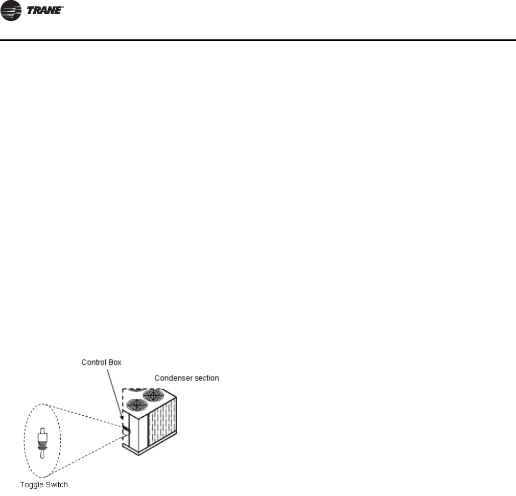
Startup
64 RT-SVX34H-EN
outputs is available. This method initiates the different
components of the unit, one at a time, when a specific
resistance value is placed across the two test
terminals. The unit will remain in the specific test mode
for approximately one hour even though the
resistance is left on the test terminals.
3. Auto Test Mode - This method is not recommended for
startup due to the short timing between individual
component steps. This method initiates the different
components of the unit, one at a time, when a jumper
is installed across the test terminals. The unit will start
the first test step and change to the next step every 30
seconds. At the end of the test mode, control of the unit
will automatically revert to the applied “System”
control method.
For Constant Volume or Variable Air Volume test steps, test
modes, and step resistance values to cycle the various
components, refer to Table 38, p. 65 - Table 43, p. 67.
Service Test Switch Location
A toggle service switch has been offered as a standard
option to provide hassle free startup option for the service
person in the field. This toggle switch is located in the low
voltage section of the control box.
Table 37. Service test switch
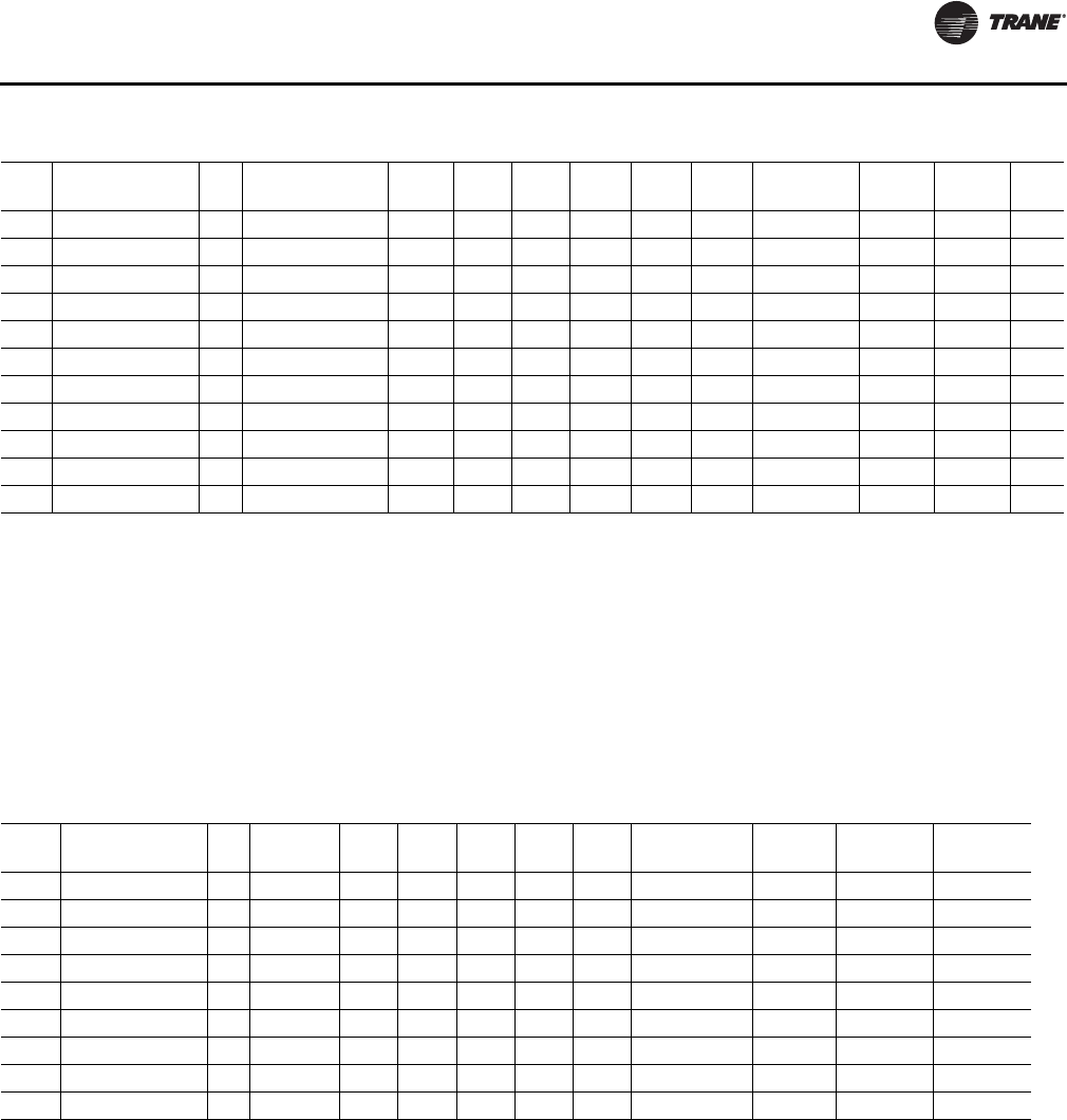
Startup
RT-SVX34H-EN 65
Table 38. Test mode states for traditional VAV units with modulating dehumidification and staged heat
TEST
STEP MODE FAN VFD COMMAND1ECON4COMP
1COMP
2COMP
3HEAT
1HEAT
2PUMPOUT
3COOL
VALVE REHEAT
VALVE VAV
BOX5
1 VFD SIGNAL 100% OFF 100% (10VDC) CLOSED OFF OFF OFF OFF OFF OFF 100% 0% ON
2 VFD SIGNAL 0% OFF 0% (0 VDC) CLOSED OFF OFF OFF OFF OFF OFF 100% 0% ON
3 MIN VENT ON IN-CONTROL MIN OFF OFF OFF OFF OFF OFF 100% 0% ON
4 ECON TEST OPEN ON IN-CONTROL OPEN OFF OFF OFF OFF OFF OFF 100% 0% ON
5 COOL 1 ON IN-CONTROL MIN ON OFF OFF OFF OFF IN-CONTROL 100% 0% ON
6 COOL 22ON IN-CONTROL MIN ON2ON2OFF OFF OFF IN-CONTROL 100% 0% ON
7 COOL 3 ON IN-CONTROL MIN ON ON ON OFF OFF IN-CONTROL 100% 0% ON
8 REHEAT ON IN-CONTROL MIN ON ON ON OFF OFF IN-CONTROL 50% 50% ON
9 HEAT 1 ON IN-CONTROL MIN OFF OFF OFF ON OFF OFF 100% 0% ON
10 HEAT 2 ON IN-CONTROL MIN OFF OFF OFF ON ON OFF 100% 0% ON
11 RESET
Notes: 2 & 3 Stage Standard Efficiency Units:
1. For Traditional VAV units, the VFD Command when “In-Control” will be controlled based on Supply Air Pressure Requirements. For SZ VAV units, the
VFD Command will be at discrete points during Test Mode.
2. For 27.5-35T units, both compressors will be energized during the Cool 2 Step. For 40-50T units, only Compressor 2 will be energized during the Cool
2 Step.
3. The Reheat Pumpout relay will be energized any time the Reheat circuit is energized in active Cooling Mode.
4. For units with Statitrac installed, the Exhaust Damper will track the Economizer position during Service Test Mode and the Exhaust Fan will be
energized once the Economizer rises above the Exhaust Enable Setpoint.
5. Heating will not be energized during Service Test until the 6 minute VAV Box ON timer has expired.
Notes: 5 Stage High Efficiency Units:
Compressor 1 is the smaller compressor on the circuit.
Condenser fans are controlled as defined for normal operation.
Exhaust fan operates as defined for normal operation based on economizer position.
When Compressor 1 is energized with either C1, C2, or with both for 30 minutes continuously, C3 will be required to de-energize for 30 seconds.
Table 39. Test mode states for CV units with modulating dehumidification and staged heat
TEST
STEP MODE FAN ECON3COMP
1COMP
2COMP
3HEAT
1HEAT
2PUMPOUT
2COOL
VALVE REHEAT
VALVE VAV BOX4
1 FAN ON ON MIN OFF OFF OFF OFF OFF OFF 100% 0% ON
2 ECONOMIZER ON OPEN OFF OFF OFF OFF OFF OFF 100% 0% ON
3 COOL 1 ON MIN ON OFF OFF OFF OFF IN-CONTROL 100% 0% ON
4 COOL 21ON MIN ON1ON1OFF OFF OFF IN-CONTROL 100% 0% ON
5 COOL 3 ON MIN ON ON ON OFF OFF IN-CONTROL 100% 0% ON
6 REHEAT ON MIN ON ON ON OFF OFF IN-CONTROL 50% 50% ON
7 HEAT 1 ON MIN OFF OFF OFF ON OFF OFF 100% 0% ON
8 HEAT 2 ON MIN OFF OFF OFF ON ON OFF 100% 0% ON
9 RESET
Notes: 2 & 3 Stage Standard Efficiency Units:
1. For 27.5-35T units, both compressors will be energized during the Cool 2 Step. For 40-50T units, only Compressor 2 will be energized during the
Cool 2 Step.
2. The Reheat Pumpout relay will be energized any time the Reheat circuit is energized in active Cooling Mode.
3. For units with Statitrac installed, the Exhaust Damper will track the Economizer position during Service Test Mode and the Exhaust Fan will be
energized once the Economizer rises above the Exhaust Enable Setpoint.
4. Heating will not be energized during Service Test until the 6 minute VAV Box ON timer has expired.
Notes: 5 Stage High Efficiency Units:
Compressor 1 is the smaller compressor on the circuit.
Condenser fans are controlled as defined for normal operation.
Exhaust fan operates as defined for normal operation based on economizer position.
When Compressor 1 is energized with either C1, C2, or with both for 30 minutes continuously, C3 will be required to de-energize for 30 seconds.

Startup
66 RT-SVX34H-EN
Table 40. Test mode states for SZ VAV units with modulating dehumidification and staged heat
TEST
STEP MODE FAN VFD COMMAND1ECON4COMP
1COMP
2COMP
3HEAT
1HEAT
2PUMPOUT
3COOL
VALVE REHEAT
VALVE
1 FAN ON ON 45% (0 VDC) MIN OFF OFF OFF OFF OFF OFF 100% 0%
2 ECONOMIZER ON 45% (0 VDC) OPEN OFF OFF OFF OFF OFF OFF 100% 0%
3 COOL 1 ON 80% (6.67 VDC) MIN ON OFF OFF OFF OFF IN-CONTROL 100% 0%
4COOL 2
2ON IN-CONTROL MIN ON2ON2OFF OFF OFF IN-CONTROL 100% 0%
5 COOL 3 ON IN-CONTROL MIN ON ON ON OFF OFF IN-CONTROL 100% 0%
6 REHEAT ON 73% (5.24 VDC) MIN ON ON ON OFF OFF IN-CONTROL 50% 50%
7 HEAT 1 ON 100% (10 VDC) MIN OFF OFF OFF ON OFF OFF 100% 0%
8 HEAT 2 ON 100% (10 VDC) MIN OFF OFF OFF ON ON OFF 100% 0%
9RESET
Notes: 2 & 3 Stage Standard Efficiency Units:
1. For Traditional VAV units, the VFD Command when “In-Control” will be controlled based on Supply Air Pressure Requirements. For SZ VAV units, the
VFD Command will be at discrete points during Test Mode.
2. For 27.5-35T units, both compressors will be energized during the Cool 2 Step. For 40-50T units, only Compressor 2 will be energized during the Cool
2 Step.
3. The Reheat Pumpout relay will be energized any time the Reheat circuit is energized in active Cooling Mode.
4. For units with Statitrac installed, the Exhaust Damper will track the Economizer position during Service Test Mode and the Exhaust Fan will be energized
once the Economizer rises above the Exhaust Enable Setpoint.
Notes: 5 Stage High Efficiency Units:
Compressor 1 is the smaller compressor on the circuit.
Condenser fans are controlled as defined for normal operation.
Exhaust fan operates as defined for normal operation based on economizer position.
When Compressor 1 is energized with either C1, C2, or with both for 30 minutes continuously, C3 will be required to de-energize for 30 seconds.
Table 41. Test mode states for traditional VAV units with modulating dehumidification and modulating heat
TEST
STEP MODE FAN VFD COMMAND1ECON4COMP
1COMP
2COMP
3HEAT
OUTPUT PUMPOUT3COOL
VALVE REHEAT
VALVE VAV
BOX5
1 VFD SIGNAL 100% OFF 100% (10VDC) CLOSED OFF OFF OFF OFF OFF 100% 0% ON
2 VFD SIGNAL 0% OFF 0% (0 VDC) CLOSED OFF OFF OFF OFF OFF 100% 0% ON
3 MIN VENT ON IN-CONTROL MIN OFF OFF OFF OFF OFF 100% 0% ON
4 ECON TEST OPEN ON IN-CONTROL OPEN OFF OFF OFF OFF OFF 100% 0% ON
5 COOL 1 ON IN-CONTROL MIN ON OFF OFF OFF IN-CONTROL 100% 0% ON
6COOL 2
2ON IN-CONTROL MIN ON2ON2OFF OFF IN-CONTROL 100% 0% ON
7 COOL 3 ON IN-CONTROL MIN ON ON ON OFF IN-CONTROL 100% 0% ON
8 REHEAT ON IN-CONTROL MIN ON ON ON OFF IN-CONTROL 50% 50% ON
9 HEAT 1 ON IN-CONTROL MIN OFF OFF OFF 50% OFF 100% 0% ON
10 HEAT 2 ON IN-CONTROL MIN OFF OFF OFF 100% OFF 100% 0% ON
11 RESET
Notes: 2 & 3 Stage Standard Efficiency Units:
1. For Traditional VAV units, the VFD Command when “In-Control” will be controlled based on Supply Air Pressure Requirements. For SZ VAV units,
the VFD Command will be at discrete points during Test Mode.
2. For 27.5-35T units, both compressors will be energized during the Cool 2 Step. For 40-50T units, only Compressor 2 will be energized during the
Cool 2 Step.
3. The Reheat Pumpout relay will be energized any time the Reheat circuit is energized in active Cooling Mode.
4. For units with Statitrac installed, the Exhaust Damper will track the Economizer position during Service Test Mode and the Exhaust Fan will be
energized once the Economizer rises above the Exhaust Enable Setpoint.
5. Heating will not be energized during Service Test until the 6 minute VAV Box ON timer has expired.
Notes: 5 Stage High Efficiency Units:
Compressor 1 is the smaller compressor on the circuit.
Condenser fans are controlled as defined for normal operation.
Exhaust fan operates as defined for normal operation based on economizer position.
When Compressor 1 is energized with either C1, C2, or with both for 30 minutes continuously, C3 will be required to de-energize for 30 seconds.

Startup
RT-SVX34H-EN 67
Table 42. Test mode states for CV units with modulating dehumidification and modulating heat
TEST
STEP MODE FAN ECON3COMP
1COMP
2COMP
3HEAT
OUTPUT PUMPOUT2COOL
VALVE REHEAT
VALVE VAV BOX4
1 FAN ON ON MIN OFF OFF OFF OFF OFF 100% 0% ON
2 ECONOMIZER ON OPEN OFF OFF OFF OFF OFF 100% 0% ON
3 COOL 1 ON MIN ON OFF OFF OFF IN-CONTROL 100% 0% ON
4COOL 2
1ON MIN ON1ON1OFF OFF IN-CONTROL 100% 0% ON
5 COOL 3 ON MIN ON ON ON OFF IN-CONTROL 100% 0% ON
6 REHEAT ON MIN ON ON ON OFF IN-CONTROL 50% 50% ON
7 HEAT 1 ON MIN OFF OFF OFF 50% OFF 100% 0% ON
8 HEAT 2 ON MIN OFF OFF OFF 100% OFF 100% 0% ON
9RESET
Notes: 2 & 3 Stage Standard Efficiency Units:
1. For 27.5-35T units, both compressors will be energized during the Cool 2 Step. For 40-50T units, only Compressor 2 will be energized during
the Cool 2 Step.
2. The Reheat Pumpout relay will be energized any time the Reheat circuit is energized in active Cooling Mode.
3. For units with Statitrac installed, the Exhaust Damper will track the Economizer position during Service Test Mode and the Exhaust Fan will be
energized once the Economizer rises above the Exhaust Enable Setpoint.
4. Heating will not be energized during Service Test until the 6 minute VAV Box ON timer has expired.
Notes: 5 Stage High Efficiency Units:
Compressor 1 is the smaller compressor on the circuit.
Condenser fans are controlled as defined for normal operation.
Exhaust fan operates as defined for normal operation based on economizer position.
When Compressor 1 is energized with either C1, C2, or with both for 30 minutes continuously, C3 will be required to de-energize for 30 seconds.
Table 43. Test mode states for SZ VAV units with modulating dehumidification and modulating heat
TEST
STEP MODE FAN VFD COMMAND1ECON4COMP
1COMP
2COMP
3HEAT
OUTPUT PUMPOUT3COOL
VALVE REHEAT
VALVE
1 FAN ON ON 45% (0 VDC) MIN OFF OFF OFF 0% OFF 100% 0%
2 ECONOMIZER ON 45% (0 VDC) OPEN OFF OFF OFF 0% OFF 100% 0%
3 COOL 1 ON 80% (6.67 VDC) MIN ON OFF OFF 0% IN-CONTROL 100% 0%
4COOL 2
2ON IN-CONTROL MIN ON2ON2OFF 0% IN-CONTROL 100% 0%
5 COOL 3 ON IN-CONTROL MIN ON ON ON 0% IN-CONTROL 100% 0%
6 REHEAT ON 73% (5.24 VDC) MIN ON ON ON 0% IN-CONTROL 50% 50%
7 HEAT 1 ON 100% (10 VDC) MIN OFF OFF OFF 50% OFF 100% 0%
8 HEAT 2 ON 100% (10 VDC) MIN OFF OFF OFF 100% OFF 100% 0%
9RESET
Notes: 2 & 3 Stage Standard Efficiency Units:
1. For Traditional VAV units, the VFD Command when “In-Control” will be controlled based on Supply Air Pressure Requirements. For SZ VAV units,
the VFD Command will be at discrete points during Test Mode.
2. For 27.5-35T units, both compressors will be energized during the Cool 2 Step. For 40-50T units, only Compressor 2 will be energized during the
Cool 2 Step.
3. The Reheat Pumpout relay will be energized any time the Reheat circuit is energized in active Cooling Mode.
4. For units with Statitrac installed, the Exhaust Damper will track the Economizer position during Service Test Mode and the Exhaust Fan will be
energized once the Economizer rises above the Exhaust Enable Setpoint.
Notes: 5 Stage High Efficiency Units:
Compressor 1 is the smaller compressor on the circuit.
Condenser fans are controlled as defined for normal operation.
Exhaust fan operates as defined for normal operation based on economizer position.
When Compressor 1 is energized with either C1, C2, or with both for 30 minutes continuously, C3 will be required to de-energize for 30 seconds.

Startup
68 RT-SVX34H-EN
Verifying Proper Fan Rotation
Using Table 38, p. 65 to Table 43, p. 67 as a reference,
momentarily jump across the test terminals to start the
Minimum Ventilation Test.
The Exhaust Fan will start anytime the economizer damper
position is equal to or greater than the exhaust fan
setpoint.
The economizer will drive to the minimum position
setpoint, exhaust fans may start at random, and the supply
fan will start.
Once the supply fan has started, check for proper rotation.
The direction of rotation is indicated by an arrow on the fan
housing.
If the fan is rotating backwards, open the main power
disconnect switch upstream of the unit terminal block or
the unit factory mounted disconnect switch.
Interchange any two of the field connected power wires at
the unit terminal block or factory mounted disconnect
switch.
Note: Interchanging “Load” side power wires at the
supply fan contactor will only affect the Fan
Rotation. Ensure that the voltage phase sequence
at the main unit terminal block or the unit mounted
disconnect switch is ABC as outlined in “Electrical
Phasing,” p. 62.
Verifying Proper Air Flow (CFM) -
CV or VFD's
1. All systems - Set the minimum position setting for the
economizer to 0º using the setpoint potentiometer
located on the Economizer Actuator in the return
section with the supply fan “On” and rotating in the
proper direction:
CV applications - Measure the amperage at the supply
fan contactor and compare it with the full load amp
(FLA) rating stamped on the motor nameplate.
VFD's - With the O/A dampers fully closed, read the
amperage displayed on the VFD screen and compare it
to the motor nameplate.
Note: On VAV applications, the VFD will be under control
of the discharge Static Pressure setpoint for the
first six minutes of this test mode. Verify that the
VFD output is at 60 Hz before measuring the fan
motor amps.
If the actual amperage exceeds the nameplate value,
static pressure is less than design and air flow is too
high. If the actual amperage is below the nameplate
value, static pressure is greater than design and air
flow is too low.
2. To determine the actual CFM (within + 5%), plot the
fan's operating RPM and the Theoretical BHP onto the
appropriate Fan Performance Curve in Figure 48, p. 69
and Figure 49, p. 69.
Theoretical BHP Formula:
Where the two points intersect, read straight down to the
CFM line. Use Table 45, p. 71 to select a new fan drive if the
CFM is not within specifications.
WARNING
Rotating Components!
The following procedure involves working with live and
exposed rotating components. Have a qualified or
licensed service individual who has been properly
trained in handling exposed rotating components,
perform these tasks. Failure to follow all safety
precautions could result in rotating components
cutting and slashing technician which could result in
death or serious injury.
WARNING
Hazardous Voltage!
Disconnect all electric power, including remote
disconnects before servicing. Follow proper lockout/
tagout procedures to ensure the power can not be
inadvertently energized. Failure to disconnect power
before servicing could result in death or serious injury.
Actual Motor Amps
Motor Nameplate Amps
----------------------------- ------------------------------------------- Motor HP Theoretical BHP =r

Startup
RT-SVX34H-EN 69
Figure 48. Supply fan performance curves 27.5 - 35 ton — 60Hz
0 2000 4000 6000 8000 10000 12000 14000 16000 18000 20000 22000 24000 26000
0.0
0.5
1.0
1.5
2.0
2.5
3.0
3.5
4.0
Supply Fan Performance 27-35T
90% WOCFM
80% WOCFM
70% WOCFM
60% WOCFM
50% WOCFM
15 HP
10 HP
7.5 HP
5 HP
3 HP
800 RPM
700 RPM
600 RPM
500 RPM
400 RPM
Volumetric Airflow Rate(CFM)
Static Presure(InWC)
Figure 49. Supply fan performance curves 40 and 50 ton — 60Hz
0 2000 4000 6000 8000 10000 12000 14000 16000 18000 20000 22000 24000 26000 28000
0
1
2
3
4
5
90% WOCFM
80% WOCFM
70% WOCFM
60% WOCFM
50% WOCFM
40% WOCFM
20 HP
15 HP
10 HP
7.5 HP
800 RPM
750 RPM
700 RPM
650 RPM
600 RPM
550 RPM
500 RPM
450 RPM
400 RPM
350 RPM
300 RPM
Volumetric Airflow Rate(CFM)
Supply Fan Performance 40 and 50 Ton
Static Presure(InWC)

Startup
70 RT-SVX34H-EN
Figure 50. Supply fan performance — 22.9-29.2 Tons — 50Hz
0 2000 4000 6000 8000 10000 12000 14000 16000 18000 20000 22000 24000 26000
0.0
0.5
1.0
1.5
2.0
2.5
3.0
3.5
4.0
(0.0)
(125)
(249)
(374)
(498)
(623)
(747)
(872)
(996)
L/S in 1000's
(0) (.94) (1.89) (2.83) (3.78) (4.72) (5.66) (6.61) (7.55) (8.5) (9.44) (10.38) (11.33) (12.27)
Supply Fan Performance
90% WOCFM
80% WOCFM
70% WOCFM
60% WOCFM
50% WOCFM
15 HP
10 HP
7.5 HP
5 HP
3 HP
800 RPM
700 RPM
600 RPM
500 RPM
400 RPM
Volumetric Airflow Rate(CFM)
Static Presure(InWC)
Figure 51. Supply fan performance — 33.3 and 41.7 Ton (IP) — 50Hz
0 2000 4000 6000 8000 10000 12000 14000 16000 18000 20000 22000 24000 26000 28000
0
1
2
3
4
5(1245)
(0.0)
(249)
(498)
(747)
(996)
L/S in 1000's
(0) (.94) (1.89) (2.83) (3.78) (4.72) (5.66) (6.61) (7.55) (8.5) (9.44) (10.38) (11.33) (12.27) (13.22)
90% WOCFM
80% WOCFM
70% WOCFM
60% WOCFM
50% WOCFM
40% WOCFM
20 HP
15 HP
10 HP
7.5 HP
800 RPM
750 RPM
700 RPM
650 RPM
600 RPM
550 RPM
500 RPM
450 RPM
400 RPM
350 RPM
300 RPM
Volumetric Airflow Rate(CFM)
Supply Fan Performance 40 and 50 Ton
Static Presure(InWC)

Startup
RT-SVX34H-EN 71
Table 44. TC*/YC* 300 - 600 MBH economizer (R/A) damper pressure drop(a) — 60 Hz
Unit
Capacity Airflow
(Cfm) Pressure
Drop(b) Unit
Capacity Airflow
(Cfm) Pressure
Drop(b)Unit
Capacity Airflow
(Cfm) Pressure
Drop(b)
27.5
8000 0.035
30
9000 0.042
35
10000 0.051
8000 0.035 9000 0.042 10000 0.051
8500 0.038 9500 0.046 10500 0.056
9000 0.042 10000 0.051 11000 0.061
9500 0.046 10500 0.056 11500 0.067
10000 0.051 11000 0.061 12000 0.073
10500 0.056 11500 0.067 12500 0.095
11000 0.061 12000 0.073 14000 0.103
11500 0.067 12500 0.08 14500 0.111
12000 0.073 13000 0.087
12500 0.08
40
12000 0.072
50
15000 0.098
12500 0.075 15500 0.104
13000 0.079 16000 0.11
13500 0.083 16500 0.117
14000 0.087 17000 0.124
14500 0.092 17500 0.132
15000 0.098 18000 0.14
15500 0.104 18500 0.149
16000 0.11 19000 0.159
16500 0.117 19500 0.168
17000 0.124 20000 0.179
17500 0.132
18000 0.14
(a)Static Pressure Drops for the return air damper must be added to the system external static pressure as an
accessory when using the fan performance tables and the fan curves to determine actual fan performance.
(b)Pressure Drops are listed in inches of water column.
Table 45. Supply fan drive selection — 60Hz
7.5 HP 10 HP 15 HP 20 HP
Nominal
Tons RPM Drive
No. RPM Drive
No. RPM Drive
No. RPM Drive
No.
27.5T
550 A 700 D
600 B 750(a)
(a)For YC gas/electric only.
E
650 C
30T
550 A 700 D
600 B 750 E
650 C
35T 600 B 650 C 790(b)
(b)For TC and TE Cooling and Electric Heat units only.
F
700 D 800(a) G
40T
500 H 625 L
525 J 675 M
575 K 725 N
50T 525 J 625 L 725 N
575 K 675 M

Startup
72 RT-SVX34H-EN
Table 46. Component static pressure drops (in. W.G.)1—60 Hz
Nominal
Tons
CFM
Std
Air
Heating System Standard
Efficiency
ID Coil
High
Efficiency
ID Coil
Filters2
Economizer
Gas Heat Electric Heat3Throw
-away MERV 8
High Eff.
MERV
14 High
Eff. Hot
Gas
Reheat
CoilLow High 1
Element 2
Elements Dry Wet Dry Wet 2" 2" 4" 4"
27½
8000 0.08 0.06 0.05 0.06 0.12 0.19 0.16 0.25 0.08 0.12 0.11 0.33 0.04 0.08
9000 0.1 0.08 0.07 0.07 0.14 0.22 0.19 0.29 0.09 0.14 0.13 0.39 0.04 0.10
10000 0.13 0.1 0.08 0.09 0.17 0.26 0.23 0.34 0.1 0.16 0.15 0.45 0.05 0.12
11000 0.15 0.12 0.1 0.11 0.20 0.30 0.27 0.39 0.12 0.2 0.17 0.52 0.06 0.14
12000 0.18 0.14 0.12 0.13 0.23 0.34 0.31 0.45 0.13 0.21 0.2 0.59 0.07 0.17
30
9000 0.1 0.08 0.07 0.07 0.14 0.22 0.19 0.29 0.09 0.14 0.13 0.39 0.04 0.10
10000 0.13 0.1 0.08 0.09 0.17 0.26 0.23 0.34 0.1 0.16 0.15 0.45 0.05 0.12
11000 0.15 0.12 0.1 0.11 0.20 0.30 0.27 0.39 0.12 0.2 0.17 0.52 0.06 0.14
12000 0.18 0.14 0.12 0.13 0.23 0.34 0.31 0.45 0.14 0.23 0.21 0.59 0.07 0.17
13000 0.21 0.16 0.14 0.15 0.27 0.38 0.35 0.50 0.15 0.26 0.23 0.66 0.09 0.20
35
10500 0.14 0.11 0.09 0.1 0.25 0.37 0.25 0.37 0.11 0.18 0.16 0.48 0.06 0.13
11500 0.17 0.13 0.11 0.12 0.29 0.42 0.29 0.42 0.13 0.21 0.19 0.55 0.07 0.16
12500 0.2 0.15 0.13 0.14 0.33 0.48 0.33 0.48 0.14 0.24 0.21 0.62 0.08 0.18
13500 0.23 0.18 0.15 0.16 0.38 0.53 0.38 0.53 0.15 0.26 0.23 0.70 0.1 0.22
14500 0.26 0.2 0.18 0.19 0.42 0.59 0.42 0.59 0.17 0.3 0.27 0.77 0.11 0.25
40
12000 0.01 0.03 0.08 0.13 0.24 0.36 0.30 0.45 0.1 0.19 0.17 0.48 0.07 0.06
13000 0.01 0.04 0.1 0.15 0.28 0.41 0.35 0.51 0.12 0.23 0.2 0.53 0.08 0.07
14000 0.02 0.05 0.11 0.18 0.31 0.46 0.39 0.57 0.13 0.25 0.22 0.59 0.09 0.08
15000 0.02 0.05 0.13 0.2 0.35 0.50 0.44 0.63 0.14 0.28 0.24 0.66 0.1 0.09
16000 0.02 0.06 0.15 0.23 0.39 0.55 0.49 0.69 0.15 0.31 0.27 0.72 0.11 0.10
17000 0.02 0.07 0.17 0.26 0.43 0.60 0.54 0.75 0.17 0.35 0.3 0.79 0.12 0.11
50
15000 0.02 0.05 0.13 0.2 0.44 0.63 0.44 0.63 0.14 0.28 0.24 0.66 0.1 0.09
16000 0.02 0.06 0.15 0.23 0.49 0.69 0.49 0.69 0.15 0.31 0.27 0.72 0.11 0.10
17000 0.02 0.07 0.17 0.26 0.54 0.75 0.54 0.75 0.17 0.35 0.3 0.79 0.12 0.11
18000 0.03 0.08 0.19 0.29 0.59 0.82 0.59 0.82 0.18 0.38 0.33 0.85 0.14 0.13
19000 0.03 0.08 0.21 0.32 0.65 0.89 0.65 0.89 0.19 0.42 0.35 0.92 0.16 0.14
20000 0.03 0.09 0.23 0.36 0.71 0.96 0.71 0.96 0.2 0.45 0.38 0.99 0.18 0.16
Notes:
1. Static pressure drops of accessory components must be added to external static pressure to enter fan selection tables.
2. Throwaway filter option limited to 300 ft/min face velocity.
3. Electric Heaters 36-54 KW contain 1 element; 72-108 KW 2 elements.

Startup
RT-SVX34H-EN 73
Table 47. Component static pressure drops in. wg (I-P) — 50 Hz
Nominal
Std Tons
(kW) CFM
Std Air
Heating System
High
Efficiency
ID Coil
Filters
Economizer
Hot
Gas
Reheat
Coil
Gas Heat Electric Heat
Standard
Efficiency
ID Coil Throw-
away MERV 8
High Eff.
MERV
14 High
Eff.
Low High 1
Element 2
Elements Dry Wet Dry Wet 2” 2” 4” 4”
23 (80)
6670 0.07 0.05 0.04 0.05 0.09 0.14 0.12 0.19 0.05 0.08 0.07 0.20 0.331 0.05
7500 0.08 0.07 0.06 0.06 0.11 0.17 0.14 0.23 0.07 0.11 0.1 0.24 0.04 0.07
8330 0.1 0.08 0.07 0.08 0.13 0.20 0.17 0.26 0.08 0.13 0.12 0.28 0.049 0.08
9170 0.13 0.1 0.08 0.09 0.15 0.23 0.20 0.30 0.09 0.15 0.14 0.32 0.059 0.10
10000 0.15 0.12 0.1 0.11 0.17 0.26 0.23 0.34 0.11 0.18 0.16 0.37 0.07 0.12
25 (88)
7500 0.08 0.07 0.06 0.06 0.11 0.17 0.14 0.23 0.07 0.11 0.1 0.24 0.04 0.07
8330 0.1 0.08 0.07 0.08 0.13 0.20 0.17 0.26 0.08 0.13 0.12 0.28 0.049 0.08
9170 0.13 0.1 0.08 0.09 0.15 0.23 0.20 0.30 0.09 0.15 0.14 0.32 0.059 0.10
10000 0.15 0.12 0.1 0.11 0.17 0.26 0.23 0.34 0.11 0.18 0.17 0.37 0.07 0.12
29 (103)
8750 0.11 0.09 0.08 0.08 0.18 0.28 0.18 0.28 0.09 0.15 0.13 0.30 0.054 0.09
9580 0.14 0.11 0.09 0.1 0.21 0.32 0.21 0.32 0.1 0.17 0.16 0.34 0.065 0.11
11200 0.19 0.15 0.13 0.14 0.28 0.41 0.28 0.41 0.12 0.21 0.19 0.43 0.077 0.15
12100 0.22 0.17 0.15 0.16 0.31 0.46 0.31 0.46 0.13 0.22 0.21 0.48 0.091 0.17
33 (118)
10000 0.01 0.03 0.07 0.11 0.18 0.28 0.22 0.35 0.11 0.18 0.16 0.37 0.070 0.04
10800 0.01 0.03 0.08 0.13 0.20 0.31 0.25 0.39 0.12 0.21 0.18 0.41 0.076 0.05
11700 0.01 0.04 0.1 0.15 0.23 0.35 0.29 0.44 0.13 0.23 0.2 0.46 0.085 0.05
12500 0.01 0.04 0.11 0.17 0.26 0.39 0.32 0.48 0.14 0.26 0.23 0.50 0.096 0.06
13300 0.02 0.05 0.12 0.19 0.29 0.42 0.36 0.53 0.15 0.28 0.25 0.55 0.107 0.07
14200 0.02 0.06 0.14 0.22 0.32 0.46 0.40 0.58 0.17 0.32 0.28 0.61 0.12 0.08
42 (146)
12500 0.01 0.04 0.11 0.17 0.33 0.48 0.33 0.48 0.14 0.26 0.23 0.50 0.095 0.06
13300 0.02 0.05 0.12 0.19 0.36 0.53 0.36 0.53 0.15 0.28 0.25 0.55 0.108 0.07
14200 0.02 0.06 0.16 0.24 0.40 0.58 0.40 0.58 0.17 0.34 0.29 0.61 0.12 0.08
15800 0.02 0.07 0.18 0.27 0.48 0.68 0.48 0.68 0.19 0.38 0.34 0.71 0.136 0.10
16700 0.03 0.08 0.2 0.3 0.53 0.74 0.53 0.74 0.2 0.41 0.36 0.77 0.155 0.11
Note: Static pressure drops of accessory components must be added to external static pressure to enter fan performance tables.

Startup
74 RT-SVX34H-EN
Table 48. Component static pressure drops Pa (SI) — 50 Hz
Nominal
Std Tons
(kW) L/s
Std Air
Heating System Filters
Gas Heat Electric Heat ID Coil Throw-
away MERV 8 High
Eff. MERV14
High Eff
Low High 1
Element 2
Element Dry Wet Adder 50 mm 100
mm 100 mm Economizer
80 (23)
3150 17 13 11 12 21 34 12 19 17 38 8
3540 21 16 14 15 26 41 17 26 24 45 10
3930 26 20 17 19 30 48 19 31 29 50 12
4320 31 24 21 23 36 55 22 36 34 57 15
4720 37 29 25 27 41 62 26 43 38 65 17
88 (25)
3540 21 16 14 15 26 41 17 26 24 45 10
3930 26 20 17 19 30 48 19 31 29 50 12
4320 31 24 21 23 36 55 22 36 34 57 15
5120 44 34 29 32 41 62 26 43 41 67 17
103 (29)
4130 29 22 19 21 44 68 22 36 31 55 13
4520 34 27 23 25 51 78 24 41 38 62 16
4920 41 32 27 29 66 97 29 50 46 77 19
5310 47 37 32 34 75 109 31 53 50 86 23
118 (33)
4720 2 7 18 27 43 67 26 43 38 65 17
5120 3 8 21 32 49 75 29 50 43 69 19
5510 3 10 24 37 56 84 31 55 48 77 21
5900 4 11 27 42 62 92 34 62 55 84 24
6290 4 12 31 48 69 101 36 67 60 88 27
6680 5 14 35 54 77 111 41 77 67 98 30
146 (42)
5900 4 11 27 42 78 115 34 62 55 84 24
6290 4 12 31 48 86 126 36 67 60 88 27
6680 5 14 35 54 96 139 41 82 72 100 30
7070 5 16 39 60 115 162 46 91 82 112 34
7470 6 18 44 67 126 176 48 98 86 124 39
Note: Static pressure drops of accessory components must be added to external static pressure to enter fan performance tables.

Startup
RT-SVX34H-EN 75
Exhaust Fan Operation
To start the optional power exhaust fans, use the
economizer test procedures in Table 38, p. 65 - Table 43,
p. 67 to drive the economizer dampers to the open
position. The exhaust fans will start when the damper
position is equal to or greater than the exhaust fan
setpoint. If optional power exhaust is selected, an access
door must be field-installed on the horizontal return
ductwork to provide access to exhaust fan motors.
The exhaust fan will start anytime the economizer damper
position is equal to or greater than the exhaust fan
setpoint.
Verify that the fans are operating properly and the CFM is
within the job specifications. Refer to power exhaust fan
performance tables beginning with Table 50, p. 76 for the
exhaust fan performance characteristics.
Available power adjustments:
1. The power exhaust fan(s) comes on based on the
position of the of the exhaust fan setpoint
potentiometer on the RTOM (Reliatel Options Module).
The setpoint is factory set at 25%. The exhaust fan(s)
will come on anytime the economizer damper position
is equal to or greater than the active exhaust fan
setpoint.
2. Physical damper blade stops limit the amount of
exhaust airflow by limiting the maximum opening of
the damper blades. These stops (sliding brackets
secured with wing-nuts) are present under the rain
hood on the non-modulating power exhaust option.
There is one stop on each side of each damper. The
practical range of blade position control is between
1.5" and 4.0" blade opening. The damper is wide-open
at 4.0". The stops on each side of a damper must be in
the same position, such that the damper blade
connecting member contacts the stops at the same
time.
3. The modulating power exhaust actuator tracks the
position of the economizer damper actuator such that
the power exhaust dampers proportionally follow or
track the fresh air damper position.
4. When the Statitrac option is selected, the exhaust
actuator will operate independently of the economizer
in order to relieve positive building pressure. If a Space
Pressure Transducer failure occurs, the unit will revert
back to fresh air tracking control.
5. The proportional offset between the dampers is
adjustable. The adjustment is made under the rain
hood by hole position selection on the power exhaust
actuator jack shaft on the damper linkage arm
(Figure 52, p. 76). With direct-drive ultra-low-leak
exhaust options, actuator stroke can be adjusted as
described in “Economizer Damper Adjustment,” p. 77.
The stroke limit can be set between 33% and 100% of
full stroke.
Table 49. Supply air fan drive selections — 50 Hz
Nominal
Tons
(kW)
7.5 hp (5.6
kW) 10 hp (7.5
kW) 15 hp (10
kW) 20 hp (15
kW)
rpm Drive
No rpm Drive
No rpm Drive
No rpm Drive
No
23 (80)
458A——————
500B——————
541C——————
583—583D————
625 — 625(a)
(a) For YC gas/electric only.
E————
25 (88)
458A——————
500B——————
541C——————
583—583D————
625—625E————
29 (103)
500B——————
541—541C————
583—583D————
658 — — — 658(b)
(b)For TC and TE Cooling only and with electric Heat units only.
F——
664 — — — 664(a) G——
33 (118)
417—417H————
437—437J ————
479—479K————
521 — — — 521 L — —
562 — — — 562 M — —
604 — — — 604 N — —
42 (146)
437—437J ————
479—479K————
521 — — — 521 L — —
562 — — — 562 M — —
604—————604N
WARNING
Rotating Components!
The following procedure involves working with live and
exposed rotating components. Have a qualified or
licensed service individual who has been properly
trained in handling exposed rotating components,
perform these tasks. Failure to follow all safety
precautions could result in rotating components
cutting and slashing technician which could result in
death or serious injury.

Startup
76 RT-SVX34H-EN
Note: The barometric damper continues to function as a
pressure relief damper up to the maximum stop
position.
Note: To adjust the damper blade stops, refer to figures
Figure 53, p. 76 to Figure 56, p. 77.
If the fan speed needs to be changed from the current
operating speed, refer to the unit wiring diagram and the
XTB1 and XTB2 terminal strip located in the economizer
section.
Figure 52. Exhaust damper linkage arm
Table 50. Power exhaust fan performance— 27.5-35 Ton
— 60 Hz
Power Exhaust Selection
50% (min) 100% (max)
Return Duct
Static
(in. wc)
Damper Blade Open Distance (in)
(min) (max) (min) (max)
CFM
0.0 3812 6866 7624 13742
0.1 3497 5296 6995 10591
0.2 3190 4458 6325 9000
0.3 2884 3812 5768 7635
0.4 2621 3359 5241 6719
0.5 2342 2885 4683 5771
Table 51. Power exhaust fan performance — 40-50 Ton —
60 Hz
Power Exhaust Selection
50% (min) 100% (max)
Damper Blade Open Distance (in)
Return Duct
Static (in. wc)
(min) (max) (min) (max)
CFM
0.0 4854 8035 9708 16069
0.1 4575 7410 9151 14820
0.2 4262 6450 8552 13496
0.3 4011 6027 8021 12054
0.4 3718 5526 7436 11051
0.5 3467 5186 6933 10373
Table 52. Power exhaust fan performance — 22.9 - 29.2
Ton — 50 Hz
Power Exhaust Selection
50% (min) 100% (max)
Damper Blade Open Distance (mm)
Return Duct
Static (Pa)
(min) (max) (min) (max)
L/s
0.0 1499 2701 2999 5405
24.9 1375 2083 2751 4166
49.8 1255 1753 2488 3540
74.7 1134 1499 2269 3003
99.6 1031 1321 2061 2643
124.5 921 1135 1842 2270
Table 53. Power exhaust fan performance — 33.3 - 41.7
Ton — 50 Hz
Power Exhaust Selection
50% (min) 100% (max)
Damper Blade Open Distance (mm)
Return Duct Static
(Pa)
(min) (max) (min) (max)
L/s
0.0 1909 3160 3818 6321
24.9 1800 2915 3599 5829
49.8 1676 2537 3364 5308
74.7 1577 2371 3155 4741
99.6 1462 2173 2925 4347
124.5 1364 2040 2727 4080
Figure 53. (Upflow) Tracking exhaust damper
adjustment
Table 51. Power exhaust fan performance — 40-50 Ton —
60 Hz
Tracking
Damper Minimum
Adjustment Linkage
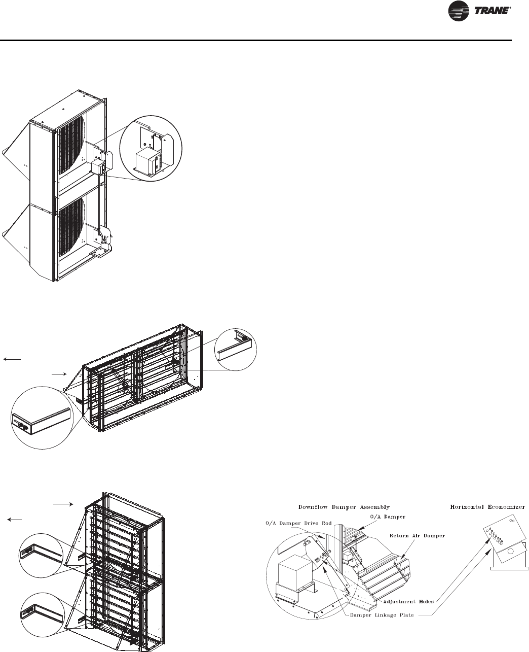
Startup
RT-SVX34H-EN 77
Economizer Damper Adjustment
Economizer (O/A) Dampers
Arbitrarily adjusting the outside air dampers to open fully
when the return air dampers are fully closed can overload
the supply fan motor or deliver higher CFM to the space
than designed. This causes higher operating duct static
pressures and over pressurization of the space when the
unit is operating in the “economizer” mode.
The purpose of adjusting the amount of O/A damper travel
is to maintain a balance or equal pressure between the
O/A dampers and the pressure drop of the return air
system. For models with standard or low-leak
economizers, the O/A and R/A damper linkage is attached
to a plate with a series of holes that allows the installer or
operator to modify the O/A damper travel to compensate
for various RA duct losses. Figure 57, p. 77 illustrates the
damper assembly and Table 54, p. 78 through Table 57,
p. 78 list the various damper positions based on the air
flow (CFM) and the return duct losses (static pressure) for
Downflow and Horizontal units.
To adjust the O/A damper for the correct pressure drop:
1. Measure the return duct static pressure.
2. Enter the calculated CFM from the previous section
“Verifying Proper Airflow” Table 44, p. 71 to obtain the
return air damper pressure drop.
3. Add the measured return duct static pressure and the
return air damper pressure drop together to obtain the
Total Return Static Pressure. Apply this calculation and
the calculated CFM to the appropriate Table 54, p. 78
through Table 57, p. 78.
4. Set the drive rod swivel to the appropriate hole
according to Table 54, p. 78 through Table 57, p. 78.
The units are shipped using hole “A” with no reference
to any specific operating condition.
Figure 54. (Horizontal) Tracking exhaust damper
adjustment
Figure 55. (Upflow) Standard exhaust maximum
damper position
Figure 56. (Horizontal) Standard exhaust maximum
damper position
Tracking Damper
Minimum
Adjustment
Linkage
Less Exhaust
More Exhaust
Less Exhaust
More Exhaust
Figure 57. Economizer (O/A) damper assembly

Startup
78 RT-SVX34H-EN
Table 54. 27.5 - 35 Ton downflow economizer (O/A)
damper static pressure setup
System
Design Return Air Duct Static + Return Air Damper
Static (Inches of Water)
CFM 0.20 0.40 0.60 0.80 1.00 1.20 1.40
Drive Rod Position
8000 B EEEEEE
8500 B D EEEEE
9500 A C EEEEE
10000 A C D EEEE
10500 A C D EEEE
11000 A B D D E E E
11500 A B C D E E E
12000 A A C D E E E
12500 A A C D D E E
13000 A A B B C D E
Table 55. 27.5 - 35 Ton horizontal economizer (O/A)
damper static pressure setup
System
Design Return Air Duct Static + Return Air Damper
Static (Inches of Water)
CFM 0.20 0.40 0.60 0.80 1.00 1.20 1.40
Drive Rod Position
8000 A F GGGGG
8500 A F GGGGG
9000 A E GGGGG
9500 A E F GGGG
10000 A D E GGGG
11000 A D E F G G G
11500 A B E F G G G
12000 A A D F G G G
12500 A A D E F G G
13000 A A D E F G G
13500 A A C E F F G
14000 A A C D E F G
14500 A A B D E F F
Table 56. 40 - 50 Ton downflow economizer (O/A)
damper static pressure setup
System
Design Return Air Duct Static + Return Air Damper
Static (Inches of Water)
CFM 0.20 0.40 0.60 0.80 1.00 1.20 1.40
Drive Rod Position
12000 A A C D E E E
12500 A A C D D E E
13000 A A B C D E E
13500 A A B C D D E
14000 A A B C C D E
14500 A A B B C D D
15000 AAABCDD
15500 AAABCDD
16000 AAABCCD
16500 AAABBCD
17000 AAABBCC
17500 AAAABCC
18000 AAAABCC
18500 AAAABBC
19000 AAAABBC
19500 AAAABBB
20000 AAAAABB
Table 57. 40 - 50 Ton horizontal economizer (O/A)
damper static pressure setup
System
Design Return Air Duct Static + Return Air Damper
Static (Inches of Water)
CFM 0.20 0.40 0.60 0.80 1.00 1.20 1.40
Drive Rod Position
12000 A B E F G G G
12500 A B D E F G G
13000 A A D E F G G
13500 A A D E F G G
14000 A A C E F F G
14500 A A C D E F F
15000 A A B D E F F
15500 A A B D E E F
16000 A A A C D E F
16500 A A A C D E F
17000AAABDEE
17500AAABDEE
18000AAABCDE
18500AAAACDE
19000AAAABDE
19500AAAABCE
20000AAAABCD

Startup
RT-SVX34H-EN 79
For Models with Ultra-Low
Leak Economizers
The installer can adjust the stroke of the direct drive
actuator on the O/A damper to compensate for various R/
A duct losses. Figure 59, p. 79 and Figure 60, p. 79
illustrate the damper & actuator assembly and Table 58,
p. 80 through Table 61, p. 80 list the various O/A actuator
limit positions based on the air flow (CFM) and the return
duct losses (static pressure) for Downflow and Horizontal
units. The actuator stroke limit can be adjusted between
33% and 100% of full stroke. To adjust the O/A damper for
the correct pressure drop:
1. Measure the return duct static pressure.
2. Enter the calculated CFM from the previous section
“Verifying Proper Air Flow (CFM) - CV or VFD's,” p. 68
to obtain the return air damper pressure drop.
3. Add the measured return duct static pressure and the
return air damper pressure drop together to obtain the
Total Return Static Pressure. Apply this calculation and
the calculated CFM to the appropriate Table 58, p. 80
through Table 61, p. 80.
4. To set the actuator stroke limit:
a. Loosen the screw that secures the angle of rotation
limiter on the actuator adjacent to the damper drive
shaft clamp.
b. Move the limiter to the desired % open position
and, making sure the limiter teeth are engaged,
retighten the screw. (See Figure 58, p. 79).
5. After setting the end stop, the actuator needs to be
cycled through its auto-adapt feature to re-scale the
control range. With 24 VAC power applied to the
actuator, turn the control signal reversing switch
forward and back again two times. Within a few
seconds, the actuator will cycle itself to the new limiter
position and then back to zero. This process may take
up to 5 minutes. The actuator will then be set to
respond to the 2-10 VDC control signal to cycle within
the new range of rotation set by the limiter. Verify that
the control signal reversing switch is set back to its
original default position - Y = 0 - same direction as
spring return. (See Figure 61, p. 79).
Figure 58. Actuator stroke limit adjustment
9
Angle of Rotation
Limiter
Scale Shows % of
Full Stroke
Figure 59. Actuator for OA damper - Downflow
Figure 60. Actuator for OA damper - horizontal
Figure 61. Actuator auto-scaling feature details
Actuator for Downow
OA Damper
Actuator for Horizontal OA Damper
Control Reversing Switch
Must Be Set to Match Spring
Return Direction

Startup
80 RT-SVX34H-EN
Table 58. 27.5 - 35 Ton downflow economizer (O/A) -
ultra-low leak economizer
System
Design Return Air Duct Static + Return Air Damper
Static (in WC)
CFM 0.20 0.40 0.60 0.80 1.00 1.20 1.40
stroke limit setting % on OA damper actuator
8000 75 55 55 55 55 55 55
8500 75 60 55 55 55 55 55
9500 100 65 55 55 55 55 55
10000 100 65 60 55 55 55 55
10500 100 65 60 60 55 55 55
11000 100 75 65 60 55 55 55
11500 100 75 65 60 55 55 55
12000 100 100 65 60 55 55 55
12500 100 100 65 60 60 55 55
13000 100 100 75 75 65 60 55
Table 59. 27.5 - 35 Ton horizontal economizer (O/A) -
ultra-low-leak economizer
System
Design Return Air Duct Static + Return Air Damper
Static (in WC)
CFM 0.20 0.40 0.60 0.80 1.00 1.20 1.40
stroke limit setting % on OA damper actuator
8000 100 45 40 40 40 40 40
8500 100 45 40 40 40 40 40
9000 100 50 40 40 40 40 40
9500 100 50 45 40 40 40 40
10000 100 60 50 40 40 40 40
11000 100 60 50 45 40 40 40
11500 100 80 50 45 40 40 40
12000 100 100 60 45 40 40 40
12500 100 100 60 50 45 40 40
13000 100 100 60 50 45 40 40
13500 100 100 70 50 45 45 40
14000 100 100 70 60 50 45 40
14500 100 100 80 60 50 45 45
Table 60. 40 - 50 Ton downflow economizer (O/A) - ultra-
low-leak economizer
System
Design Return Air Duct Static + Return Air Damper
Static (in WC)
CFM 0.20 0.40 0.60 0.80 1.00 1.20 1.40
stroke limit setting % on OA damper actuator
12000 100 100 65 60 55 55 55
12500 100 100 65 60 60 55 55
System
Design Return Air Duct Static + Return Air Damper
Static (in WC)
CFM 0.20 0.40 0.60 0.80 1.00 1.20 1.40
stroke limit setting % on OA damper actuator
13000 100 100 75 65 60 55 55
13500 100 100 75 65 60 60 55
14000 100 100 75 65 65 60 55
14500 100 100 75 75 65 60 60
15000 100 100 100 75 65 60 60
15500 100 100 100 75 65 60 60
16000 100 100 100 75 65 65 60
16500 100 100 100 75 75 65 60
17000 100 100 100 75 75 65 65
17500 100 100 100 100 75 65 65
18000 100 100 100 100 75 65 65
18500 100 100 100 100 75 75 65
19000 100 100 100 100 75 75 65
19500 100 100 100 100 75 75 75
20000 100 100 100 100 100 75 75
Table 61. 40 - 50 Ton horizontal economizer (O/A) - ultra-
low-leak economizer
System
Design Return Air Duct Static + Return Air Damper
Static (in WC)
CFM 0.20 0.40 0.60 0.80 1.00 1.20 1.40
stroke limit setting % on OA damper actuator
12000 100 80 50 45 40 40 40
12500 100 80 60 50 45 40 40
13000 100 100 60 50 45 40 40
13500 100 100 60 50 45 40 40
14000 100 100 70 50 45 45 40
14500 100 100 70 60 50 45 45
15000 100 100 80 60 50 45 45
15500 100 100 80 60 50 50 45
16000 100 100 100 70 60 50 45
16500 100 100 100 70 60 50 45
17000 100 100 100 80 60 50 50
17500 100 100 100 80 60 50 50
18000 100 100 100 80 70 60 50
18500 100 100 100 100 70 60 50
19000 100 100 100 100 80 60 50
19500 100 100 100 100 80 70 50
20000 100 100 100 100 80 70 60
Table 60. 40 - 50 Ton downflow economizer (O/A) - ultra-
low-leak economizer

Startup
RT-SVX34H-EN 81
Manual Outside Air Damper
Units ordered with the 25% manual outside air option have
two slidable dampers. By adjusting one or both, the
desired amount of fresh air entering the system can be
obtained.
To adjust the outside air damper;
1. Turn the “System” selection switch to the “Off”
position and the “Fan” selection switch (if applicable)
to the “Auto” position.
2. Close the disconnect switch or circuit protector switch
that provides the supply power to the unit's power
terminal block or the unit factory mounted disconnect
switch.
HIGH VOLTAGE IS PRESENT AT TERMINAL BLOCK
HTB1 OR UNIT DISCONNECT SWITCH.
3. Remove the mist eliminator retainer bracket and the
mist eliminators from the fresh air hood.
4. Remove the five (5) screws in the top and bottom of
each fresh air damper located inside the hood area.
5. Using the Service Test guide in Table 38, p. 65 -
Table 43, p. 67, momentarily jump across the test
terminals one time for constant volume applications,
or three consecutive times for a variable air volume
application, to start the Minimum Ventilation Test.
6. With the supply fan “On” and rotating in the proper
direction, measure the return duct static pressure.
7. U s in g Table 62, p. 81, enter the desired amount of
fresh air and the return air static pressure reading to
obtain the proper damper opening dimension.
8. Loosen the adjustment screws on each side of the
damper and slide it downward to the required opening.
9. Tighten the adjustment screws and re-install the mist
eliminators and the mist eliminator retainer bracket.
10. Open the main power disconnect or the unit mounted
disconnect switch to shut the unit off and to reset the
RTRM.
11. Before closing the disconnect switch, ensure that the
compressor discharge service valve(s), suction service
valve(s), and liquid line service valve(s) are
backseated.
WARNING
Live Electrical Components!
During installation, testing, servicing and
troubleshooting of this product, it may be necessary to
work with live electrical components. Have a qualified
licensed electrician or other individual who has been
properly trained in handling live electrical components
perform these tasks. Failure to follow all electrical safety
precautions when exposed to live electrical
components could result in death or serious injury.
Table 62. Damper adjustment
Damper Opening (In.) Return Air Static Pressure - Inches w.c.
Damper #1 Damper #2 -0.20 -0.40 -0.60 -0.80 -1.00 -1.20 -1.40 -1.60
2 0 430 590 725 840 950 1040 1120 740
4 0 780 1080 1330 1545 1730 1890 2035 2170
6 0 1185 1620 1990 2300 2575 2815 3030 3240
8 0 1530 2110 2600 3025 3390 3705 3985 4240
10 0 1930 2655 3270 3800 4250 4650 5005 5345
10 2 2295 3165 3910 4545 5095 5575 6010 6415
10 4 2660 3650 4510 5255 5905 6480 6995 7470
10 6 3010 4150 5130 5965 6690 7330 7900 8440
10 8 3345 4600 5680 6610 7410 8120 8765 9365
10 10 3690 5125 6350 7395 8295 9075 9775 10420

Startup
82 RT-SVX34H-EN
Starting the Compressor
Optional service valves must be fully opened before
startup (suction, discharge, liquid line and oil line).
Note: Service valves are standard on high efficiency
units.
Starting 27.5 to 35 Ton Standard Efficiency
Units
Install a set of service gauges onto the suction and
discharge service ports. To start the compressor test, close
the main power disconnect switch or the unit mounted
disconnect switch.
Jump across the “Test terminals” on LTB1 or toggle the
test switch three consecutive times if it is a constant
volume application, or five times if it is a variable air
volume application for two to three seconds per jump.
Refer to Table 38, p. 65 - Table 43, p. 67 for the Cooling Test
sequence.
Important: The compressors are protected from
reverse rotation caused by improper
sequencing of the customer supplied unit
power wires by the unit phase monitor. It is
imperative to verify correct sequencing of
compressor power wires to prevent
compressor failure from reverse rotation.
Refer to the unit wiring schematic and/or
wire color markers vs. the compressor
terminal block color markers.
If a scroll compressor is rotating backwards, it will not
pump and a loud rattling sound can be observed. If
allowed to run backward for even a very short period of
time, internal compressor damage may occur and
compressor life may be reduced. If allowed to run
backwards for an extended period of time, the compressor
will likely fail or the motor windings will overheat and
cause the motor winding thermostats to open. The
opening of the motor winding thermostat will cause a
“compressor trip” diagnostic and stop the compressor.
Starting 40 to 50 Ton Standard Efficiency
Units
Install a set of service gauges onto the suction and
discharge service ports of each circuit. Follow the same
procedures as above to start the first stage of compressor
operation.
After the compressor and the condenser fans have been
operating for approximately 30 minutes, use Table 71,
p. 85 through Table 89, p. 94 to determine the proper
operating pressures for that circuit.
Jump across the “Test Terminals” once again. This will
allow the second stage compressors to start. The first
stage compressor will shut off providing the 3 minute
“On” time has elapsed.
Note: When the second refrigerant circuit is requested to
operate, both compressors of the 50 ton unit will
run simultaneously. Verify that the compressors
are rotating in the correct direction.
Observe the operation of the compressor(s) and the
system operating pressures. After compressors and
condenser fans for the circuit have been operating for
approximately 30 minutes, use Table 74, p. 86 through
Table 89, p. 94 to determine the proper operating
pressures. For subcooling guidelines, refer to “Measuring
Subcooling,” p. 97.
Units with Lead/Lag function disabled, jump across the
“Test Terminals” once again. This will allow the third stage
of cooling (number one circuit) to start providing the 3
minute “Off” time has been satisfied.
Starting 27.5-50 Ton High Efficiency Units
Install a set of service gauges onto the suction and
discharge service ports of each circuit. Jump across the
"Test Terminals" on LTB1 or toggle the test switch three
consecutive times if it is a constant volume application, or
five times if it is a variable air volume application for two
to three seconds per jump in order to get to cooling stage 1.
Jump across the "Test Terminals" two more times for full
load cooling. After the compressor and the condenser fans
have been operating for approximately 30 minutes, use
Figure 71, p. 85 through Figure 89, p. 94 to determine the
proper operating pressures for that circuit.
For subcooling guidelines, refer to “Measuring
Subcooling,” p. 97.
Line Weights
The standard and high efficiency units use line weights to
dampen vibration. Do not remove, relocate, or over-torque
these weights. The torque specification for the attaching
bolts is 6 ft-lbs ± 1.0 ft-lb.
NOTICE:
Compressors Failure!
Unit must be powered and crankcase heaters energized
at least 8 hours BEFORE compressors are started. This
will protect the compressors from premature failure.
Figure 62. Compressor terminal block color markers

Startup
RT-SVX34H-EN 83
The locations of the line weights are shown in Figure 63,
p. 83, and Figure 70, p. 84.
Figure 63. Line weight locations TE, YC, TC*330, 360, &
420 standard efficiency w/o service valves
Figure 64. Line weight location TE, YC, TC*330, 360, &
420 standard efficiency with service valves
Figure 65. Line weight location TE, YC, TC*400
standard efficiency w/o service valves
0.75±0.250.75±0.25
0.75±0.25
0.75±0.25
Figure 66. Line weight location TE, YC, TC*400 & 480
standard efficiency with service valves & TE,
YC, TC*480 with reheat valve with service
valves
Figure 67. Line weight locations TE, YC, TC*500 & 600
standard efficiency w/o service valves
Figure 68. Line weight locations TE, YC, TC*500 & 600
standard efficiency with service valves
Figure 69. Line weight location TE, YC, TC*600
standard efficiency reheat with service
valves
0.25±0.25
0.75±0.25
0.75±0.25
0.25±0.25
0.75±0.25
0.25±0.25

Startup
84 RT-SVX34H-EN
Compressor Oil
Once all of the compressors have been started, verify that
the oil level is visible through the sight glass or above the
sight glass. Use appropriate lighting (flash light) to verify
the presence of oil. A tandem manifold set may have
different oil heights, but still must be visible in the sight
glass or above the sight glass.
After shutting the compressors off, check the oil’s
appearance. Discoloration of the oil indicates that an
abnormal condition has occurred. If the oil is dark,
overheating may have occurred. Potential causes of
overheating: compressor is operating at extremely high
condensing temperatures; high superheat; a compressor
mechanical failure; or, occurrence of a motor burnout. If
the oil is black and contains metal flakes, a mechanical
failure has occurred. This symptom is often accompanied
by a high compressor amperage draw.
Refer to the refrigeration system in the maintenance
section for details on testing and replacing oil.
Figure 70. Line weight location TE, YC, TC*275, 305,
350, 400, & 500 high efficiency
0.25±0.25
Top View

Startup
RT-SVX34H-EN 85
Figure 71. 27.5 Ton operating pressure — standard efficiency (60Hz)
TC, TE, YC* 330
FULL LOAD
200
250
300
350
400
450
500
550
600
650
700
100 110 120 130 14 0 150 16 0 170 180 1 90 200
Suction Pressure (Psig)
Discharge Pressure (Psig)
68/57 F I D WB/DB
74/62 F ID WB/DB
86/72 F I D WB/DB
80/67 F ID WB/DB
55 F OD Ambient
85 F OD Ambient
7 5 F OD Ambi ent
65 F OD Ambien t
115 F OD Ambi ent
105 F OD Ambient
95 F OD Ambien t
Figure 72. 30 Ton operating pressure — standard efficiency (60 Hz)
TC, TE, YC* 360
FULL LOAD
200
250
300
350
400
450
500
550
600
650
700
100 110 1 20 130 14 0 150 16 0 170 180 190 200
Suction Pressure (Psig)
Discharge Pressure (Psig)
68/57 F ID WB/DB
74/62 F ID WB/DB
86/72 F ID WB/DB
80/67 F ID WB/DB
55 F OD Ambient
85 F OD Ambient
75 F OD Ambient
65 F OD Ambient
11 5 F OD A mbient
105 F OD Ambient
95 F OD Ambient

Startup
86 RT-SVX34H-EN
Figure 73. 35 Ton operating pressure — standard efficiency (60 Hz)
TC, TE, YC* 420
FULL LOAD
200
250
300
350
400
450
500
550
600
650
700
100 110 120 130 14 0 150 16 0 170 180 1 90 200
Suction Pressure (Psig)
Discharge Pressure (Psig)
68/5 7 F ID WB/DB
74/ 62 F ID WB/DB
86/72 F ID WB/DB
80/ 67 F ID WB/DB
55 F OD Ambient
85 F OD Ambient
75 F OD Ambient
65 F OD Ambient
11 5 F OD Ambien t
10 5 F OD Am bi ent
9
5 F OD Ambien t
Figure 74. 40 Ton dual circuit operating pressure — standard efficiency (60 Hz)
TC, TE, YC* 480 Circuit #1
Full Load
200
250
300
350
400
450
500
550
600
650
700
100 110 1 20 130 14 0 150 160 170 180 1 90 200
Suction Pressure (Psig)
Discharge Pressure (Psig)
68/57 F ID WB/DB
74/ 62 F ID WB/DB
86/ 72 F ID WB/DB
80/67 F I D WB/DB
55 F OD Ambient
85 F OD Ambien t
75 F OD Am bient
6 5 F OD Ambien t
115 F OD Am bient
1 05 F OD Ambien t
95 F OD Ambient

Startup
RT-SVX34H-EN 87
Figure 75. 40 Ton dual circuit operating pressure — standard efficiency (60 Hz)
TC, TE, YC* 480 Circuit #2
Full Load
200
250
300
350
400
450
500
550
600
650
700
100 110 120 130 14 0 150 160 170 180 1 90 200
Suction Pressure (Psig)
Discharge Pressure (Psig)
68/57 F ID WB/DB
74/62 F ID WB/DB
86 /72 F ID WB/ DB
80/67 F ID WB/DB
5 5 F OD Ambient
85 F OD Ambient
75 F OD Ambient
65 F OD Ambient
115 F OD Ambie nt
105 F OD Ambient
95 F OD Ambient
Figure 76. 50 Ton dual circuit operating pressures — standard efficiency (60 Hz)
TC, TE, YC* 600 Circuit # 1
FULL LO AD
200
250
300
350
400
450
500
550
600
650
700
100 11 0 120 13 0 140 150 160 17 0 180 1 90 200
Suction Pressure (Psig)
Discharge Pressure (Psig)
68/57 F ID WB/DB
74/62 F ID WB/DB
86/72 F ID WB/DB
80/67 F ID WB/DB
55 F OD Ambien t
85 F OD Ambient
75 F OD Amb ien t
65 F OD Am bient
115 F OD Ambient
105 F OD Ambient
95 F OD Am bient

Startup
88 RT-SVX34H-EN
Figure 77. 50 Ton dual circuit operating pressures — standard efficiency (60 Hz)
TC, TE, YC* 600 Circuit # 2
FULL LOAD
200
250
300
350
400
450
500
550
600
650
700
100 110 1 20 130 14 0 150 16 0 170 180 190 200
Suction Pressure (Psig)
Discharge Pressure (Psig)
68/57 F ID WB/DB
74 /62 F ID WB/ DB
8 6/72 F I D WB /DB
80/ 67 F ID WB/D B
55 F OD Ambient
85 F OD Ambient
75 F OD Am bient
65 F OD Ambient
115 F OD Ambient
10 5 F OD Ambien t
95 F OD Ambient
Figure 78. 27.5 Ton operating pressure — high efficiency (60 Hz)
TC, TE, YC*330
FULL LOAD

Startup
RT-SVX34H-EN 89
Figure 79. 30 Ton operating pressure — high efficiency (60 Hz)
TC, TE, YC*360
FULL LOAD
Figure 80. 35 Ton operating pressure — high efficiency (60 Hz)
TC, TE, YC*420
FULL LOAD

Startup
90 RT-SVX34H-EN
Figure 81. 40Ton operating pressure — high efficiency (60 Hz)
TC, TE, YC*480
FULL LOAD
Figure 82. 50Ton operating pressure — high efficiency (60 Hz)
TC, TE, YC*600
FULL LOAD

Startup
RT-SVX34H-EN 91
Figure 83. 22.9 Ton operating pressure — standard efficiency (50 Hz)
TC, TE, YC* 275
FULL LOAD
200
250
300
350
400
450
500
550
600
650
700
100 110 1 20 130 14 0 150 160 170 180 1 90 200
Suction Pressure (Psig)
Discharge Pressure (Psig)
68/57 F ID WB/DB
74/62 F ID WB/DB
86/ 72 F ID WB/DB
80/67 F ID W B/DB
55 F OD Ambient
85 F OD Ambient
75 F OD Ambien t
65 F OD Ambient
115 F OD Ambient
10 5 F OD A mbient
95 F OD Am bi ent
Figure 84. 25.4 Ton operating pressure — standard efficiency (50 Hz)
TC, TE, YC* 305
FULL LOAD
200
250
300
350
400
450
500
550
600
650
700
100 110 120 130 14 0 150 16 0 170 180 1 90 200
Suction Pressure (Psig)
Discharge Pressure (Psig)
68/57 F ID WB/DB
74/ 62 F ID WB/DB
86 /72 F ID WB/ DB
80/67 F ID WB/DB
55 F OD Am bient
85 F OD Am bient
75 F OD Ambi ent
6 5 F OD Ambient
11 5 F OD Ambien t
10 5 F OD Ambien t
9 5 F OD A mbient

Startup
92 RT-SVX34H-EN
Figure 85. 29.2 Ton operating pressures — standard efficiency (50 Hz)
TC, TE, YC* 350
FULL LOAD
200
250
300
350
400
450
500
550
600
650
700
100 110 120 130 140 150 160 170 180 1 90 200
Suction Pressure (Psig)
Discharge Pressure (Psig)
68 /57 F ID WB/ DB
74/62 F ID WB/DB
86 /72 F ID WB/ DB
80/6 7 F ID WB/DB
55 F OD Ambi ent
8 5 F OD Ambient
75 F OD Ambi ent
6 5 F OD Ambien t
115 F OD Am bient
105 F OD Ambient
95 F OD Ambient
Figure 86. 33.3 Ton dual circuit operating pressure — standard efficiency (50 Hz)
TC, TE, YC* 400 Circuit #1
Full Load
1200
1700
2200
2700
3200
3700
4200
600 700 800 900 1000 1100 12 00 1300
Suction Pressure (KPa)
Discharge Pressure (KPa)
20.0/13.9 C ID
DB /WB
12 .8 F OD Amb ient
29.4 F OD Ambient
23.9 F OD Am bient
18.3 F OD Ambient
46.1 F OD Ambient
40.6 F OD Ambient
35.0 F OD Ambient
30.0/22.2 C ID
DB/WB
26.7/ 19.4 C ID
DB/WB
23.3/16.7 C ID
DB/WB

Startup
RT-SVX34H-EN 93
Figure 87. 33.3 Ton dual circuit operating pressure — standard efficiency (50 Hz)
TC, TE, YC* 400 Circuit #2
Full Load
1200
1700
2200
2700
3200
3700
4200
600 700 8 00 900 1 000 110 0 12 00 1300
Suction Pressure (KPa)
Discharge Pressure (KPa)
20.0/13.9 C I D
12. 8 F OD Ambient
29.4 F OD Ambient
23.9 F OD Ambient
18.3 F OD Ambient
46.1 F OD Ambie nt
40.6 F OD Ambient
35.0 F OD Ambien t
30.0/22.2 C ID
DB/ WB
26.7/19.4 C ID
DB /WB
23.3/16.7 C ID
DB/WB
Figure 88. 41.7 Ton dual circuit operating pressures — standard efficiency (50 Hz)
TC, TE, YC* 500 Circuit #1
Full Load
1200
1700
2200
2700
3200
3700
4200
600 700 800 900 1 000 1100 1200 1300
Suction Pressure (KPa)
Discharge Pressure (KPa)
20.0/13.9 C ID
DB/W B
12.8 F OD Am bient
2
9.4 F OD Ambient
23.9 F OD Ambient
18 .3 F OD Ambien t
46 .1 F OD A mbien t
40.6 F OD Ambient
35.0 F OD Am bient
30.0/ 22.2 C ID
DB/WB
2 6.7/1 9.4 C ID
DB/WB
23. 3/16. 7 C ID
DB/W B

Startup
94 RT-SVX34H-EN
Figure 89. 41.7 Ton dual circuit operating pressures — standard efficiency (50 Hz)
TC, TE, YC* 500 Circuit #2
Full Load
1200
1700
2200
2700
3200
3700
4200
600 700 800 900 1 000 1100 12 00 1300
Suction Pressure (KPa)
Discharge Pressure (KPa)
20. 0/13. 9 C ID
DB/W B
12 .8 F OD Ambien t
29. 4 F OD A mbient
23.9 F OD Ambient
18.3 F OD Ambient
46 .1 F OD Ambien t
40.6 F OD Ambient
35.0 F OD Ambient
30.0 /22.2 C ID
DB/ W B
26.7/ 19.4 C ID
DB/WB
23.3 /16.7 C ID
DB/ W B
Figure 90. 22.9 Ton operating pressure — high efficiency (50 Hz)
TC, TE, YC*275
FULL LOAD

Startup
RT-SVX34H-EN 95
Figure 91. 25.4 Ton operating pressure — high efficiency (50 Hz)
TC, TE, YC*305
FULL LOAD
Figure 92. 29.2 Ton operating pressure — high efficiency (50 Hz)
TC, TE, YC*305
FULL LOAD

Startup
96 RT-SVX34H-EN
Figure 93. 33.3 Ton operating pressure — high efficiency (50 Hz)
TC, TE, YC*400
FULL LOAD
Figure 94. 41.7 Ton operating pressure — high efficiency (50 Hz)
TC, TE, YC*500
FULL LOAD

Startup
RT-SVX34H-EN 97
Scroll Compressor Operational Noises
Because the scroll compressor is designed to
accommodate liquids (both oil and refrigerant) and solid
particles without causing compressor damage, there are
some characteristic sounds that differentiate it from those
typically associated with a reciprocating compressor.
These sounds (which are described below) are
characteristic, and do not affect the operation or reliability
of the compressor.
At Shutdown
When a Scroll compressor shuts down, the gas within the
scroll compressor expands and causes momentary
reverse rotation until the discharge check valve closes.
This results in a “flutter” type sound.
At Low Ambient Startup
When the compressor starts up under low ambient
conditions, the initial flow rate of the compressor is low
due to the low condensing pressure. This causes a low
differential across the thermal expansion valve that limits
its capacity. Under these conditions, it is not unusual to
hear the compressor rattle until the suction pressure
climbs and the flow rate increases.
During Normal Operation
The scroll compressor emits a higher frequency tone
(sound) than a reciprocating compressor.
Compressor Crankcase Heaters
Each compressor is equipped with a crankcase heater.
When the compressor is “Off”, the crankcase heater is
energized. When the compressor is “On”, the crankcase
heater is de-energized. The proper operation of the
crankcase heater is important to maintain an elevated
compressor oil temperature during the “Off” cycle which
reduces the potential for refrigerant to migrate into the
compressor oil.
If present during a compressor start, liquid refrigerant
could damage compressor bearings due to reduced
lubrication and eventually could cause compressor
mechanical failures.
Prior to the initial start or when power to the unit has been
“Off” for an extended period, allow the crankcase heater to
operate a minimum of 8 hours before starting the unit.
Charging by Subcooling
The unit is shipped with a complete refrigerant charge.
However, if it becomes necessary to add refrigerant, it
should be done so by adding charge to obtain an
acceptable subcooling as described below. Refer to the
maintenance section for proper refrigerant charging
practices.
The outdoor ambient temperature must be between 65°
and 105° F and the relative humidity of the air entering the
evaporator must be above 40 percent. When the
temperatures are outside of these ranges, measuring the
operating pressures can be meaningless.
With the unit operating at “Full Circuit Capacity”,
acceptable subcooling ranges between 14° F to 22° F.
Measuring Subcooling
1. At the liquid line service valve, measure the liquid line
pressure. Using a Refrigerant R-410A pressure/
temperature chart, convert the pressure reading into
the corresponding saturated temperature.
2. Measure the actual liquid line temperature as close to
the liquid line service valve as possible. To ensure an
accurate reading, clean the line thoroughly where the
temperature sensor will be attached. After securing the
sensor to the line, insulate the sensor and line to isolate
it from the ambient air.
Note: Glass thermometers do not have sufficient contact
area to give an accurate reading.
3. Determine the system subcooling by subtracting the
actual liquid line temperature (measured in step 2)
from the saturated liquid temperature (converted in
step 1).
Gas Heat Units
Open the main disconnect switch to shut the unit off and
to reset the RTRM.
Follow the Test Guide in Table 38, p. 65 - Table 43, p. 67 to
start the unit in the heating mode. Jumping the “Test”
terminals several times for two to three seconds will be
required.
When starting the unit for the first time or servicing the
heaters, it is a good practice to start the heater with the
main gas supply turned “Off”.
All heating units have either two stage or modulating heat
capabilities. The “High” heat models contain two heat
exchangers. In staged units, the heat exchangers operate
simultaneously at either the low or high fire state. In
modulating units, the modulating furnace fires first and
adjusts to the needed capacity. If more heat is required
WARNING
R-410A Refrigerant under Higher Pressure
than R-22!
The units described in this manual use R-410A
refrigerant which operates at higher pressures than R-
22 refrigerant. Use ONLY R-410A rated service
equipment or components with these units. For
specific handling concerns with R-410A, please contact
your local Trane representative.
Failure to use R-410A rated service equipment or
components could result in equipment exploding under
R-410A high pressures which could result in death,
serious injury, or equipment damage.
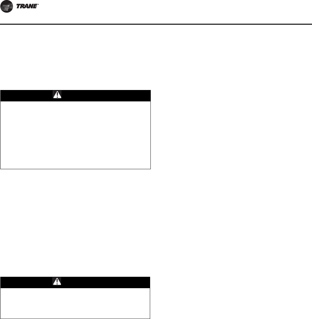
Startup
98 RT-SVX34H-EN
than the modulating can provide, the second bank is fired
at full fire and the modulating bank again adjusts to the
heating load present.
Check both ignition systems (if applicable) when going
through the test procedures.
Once the ignition system and ignitors have been checked,
open the main power disconnect switch to reset the RTRM.
Turn the main gas supply to the unit “On” and check the
gas pressure at the unit's gas train. Refer to “Installation
Piping,” p. 38 for the proper gas supply pressure and
Figure 34, p. 39 for the location of the gas pressure taps.
Close the main power disconnect switch and start the first
stage heating Test again. Wait approximately 60 seconds
for the heater to switch to low fire and check the manifold
gas pressure. The manifold pressure for a two stage
burner must be set at negative 0.2" w.c., +/- 0.05" w.c. The
manifold pressure on a modulating burner should be set
at a positive 0.5" w.c., +/-0.05” w.c. For modulating
burners, expect to see the manifold pressure reading
fluctuate while the burner is operating, but it should never
read negative.
Jump the test terminals momentarily to initiate second
stage heat operation. The combustion blower motor
should go to high speed. The second stage of heat in units
with modulating gas will initiate the second heater bank to
fire and both banks will operate at high fire. The manifold
pressures of the two heater banks in a high heat
modulating unit will be different. The pressure setting of
the two stage burner will be a negative 0.2" w.c., while the
modulating burner will be a positive 0.05" w.c.
Note: When firing a modulating unit for the first time, a
“humming”, or resonance sound may be heard.
This is an operational sound made by the burner
screen as it burns in. This sound is not a concern
unless it persists longer than the first few times the
unit is fired.
Electric Heat Units
Start the service test and check the amperage draw for
each heating stage. Refer to the heater electrical data in
Table 8, p. 28 (60 Hz) and Table 11, p. 29 (50 Hz) for the full
load amps of a specific heater size.
Once the operation of the heaters have been checked,
open the main power disconnect switch or the unit
mounted disconnect switch to shut the unit “Off” and to
reset the RTRM.
This concludes the setup and testing for the major
components and controls within the unit. Follow the Test
guide in Table 38, p. 65 - Table 43, p. 67 to verify that the
optional VFD, economizer actuator, and minimum
ventilation controls are functioning.
Final Unit Checkout
After completing all of the checkout and startup
procedures outlined in the previous sections (i.e.,
operating the unit in each of its modes through all
available stages of cooling and heating), perform these
final checks before leaving the unit:
• Verify that the RTRM is in the normal operation mode.
The LED located on the UCP module is “on” and
glowing continuously.
For Constant Volume Units
• Verify that the “Mode” selection switch and the “Zone
Temperature” setpoints are set and/or programmed at
the sensor modules.
For Variable Air Volume Units
The RTAM has input setpoint potentiometers inside the
control panel that are set at the factory which will allow the
unit to operate and maintain system control. For specific
job specifications;
• Verify that the control input potentiometers are set
according to the job specifications, i.e.;
– Outside air reset temperature - _______ Setpoint
– Reset amount °F. - _______ Setpoint
– Static pressure - _______ Setpoint
– Static pressure deadband - ________ Setpoint
– Discharge air temperature - _______Setpoint
– Morning warm up temperature - _______
Setpoint
– Exhaust Fan - _______ Setpoint
• Inspect the unit for misplaced tools, hardware and
debris.
• Verify that all unit exterior panels—including the
control panel doors—are secured in place.
WARNING
Hazardous Gases and Flammable Vapors!
Exposure to hazardous gases from fuel substances have
been shown to cause cancer, birth defects or other
reproductive harm. Improper installation, adjustment,
alteration, service or use of this product could cause
flammable mixtures and result in a fire. To avoid
hazardous gases and flammable vapors follow proper
installation and set up of this product and all warnings
as provided in this manual. Failure to follow all
instructions could result in death or serious injury.
WARNING
Hot Surfaces!
Surface temperatures may exceed 300°F (150°C) on flue
and heat exchanger components. Contact of bare skin
on hot surfaces could result in minor to severe burns.

Startup
RT-SVX34H-EN 99
For Single Zone Variable Air Volume
Units
Verify that the “Mode” selection switch and the “Zone
Temperature” setpoints are set and/or programmed at the
sensor modules.
The RTOM has input setpoint potentiometers inside the
control panel that are set at the factory which will allow the
unit to operate and maintain system control. For specific
job specifications:
• Verify that the control input potentiometers are set
according to the job specifications:
– DA Heat -_____Setpoint
– DA Cool - Fan SPD - _____Setpoint
– EXH Fan - _____Setpoint
• Inspect the unit for misplaced tools, hardware and
debris.
• Verify that all unit exterior panels—including the
control panel doors—are secured in place.

100 RT-SVX34H-EN
Pre-Installation
The checklist listed below is a summary of the steps
required to successfully install a Voyager Commercial
rooftop unit. This checklist is intended to acquaint the
installing personnel with what is required in the
installation process. It does not replace the detailed
instructions called out in the applicable sections of this
manual.
General Unit Requirements
Downflow/Upflow Models:
• An optional roof curb, specifically designed for the
Voyager commercial rooftop units is available from
Trane. The roof curb kit must be field assembled and
installed according to the latest edition of the curb
installation guide.
• Assemble and install the roof curb, including
necessary gaskets. Make sure the curb is level.
• Install and secure the ductwork to the curb.
All Units:
• Check unit for shipping damage and material shortage.
(Refer to “Unit Inspection,” p. 13).
• Rigging the unit. Refer to Figure 12, p. 20.
• Placing the unit on curb; check for levelness. See “Roof
Curb and Ductwork” on page 14.
• Ensure that the unit-to-curb seal is tight and without
buckles or cracks.
• Install an appropriate drain line to the evaporator
condensate drain connections, as required. Refer to
Figure 14, p. 23.
• Service Valve Option; See “Starting the Compressor”
on page 82.
• Return/Fresh-air damper adjustment. Refer to
“Economizer Damper Adjustment” on page 77.
• Exhaust Fan Damper Stop Adjustment. Refer to
Exhaust Damper Adjustment figures, beginning with
Figure 53, p. 76.
Electrical Requirements
(See Figure 19, “Typical field power wiring,” on page 26.)
• Verify that the electrical power supply characteristics
comply with the unit nameplate specifications.
• Inspect all control panel components; tighten any
loose connections.
• Connect properly sized and protected power supply
wiring to a field supplied/installed disconnect and unit
power terminal block HTB1, or to the optional unit-
mounted disconnect switch.
• Properly ground the unit.
Field Installed Control Wiring
(Figure 20, p. 32 and Figure 21, p. 33.)
Important: All field-installed wiring must comply with
NEC and applicable local codes.
• Complete the field wiring connections for the constant
volume controls as applicable. Refer to the “Low
Voltage Wiring” on page 30 for guidelines.
• Complete the field wiring connections for the variable
air volume controls as applicable. Refer to the “Low
Voltage Wiring” on page 30 for guidelines.
Gas Heat Requirements
(See “Installation Piping” on page 38.)
• Gas supply line properly sized and connected to the
unit gas train.
• All gas piping joints properly sealed.
• Drip leg Installed in the gas piping near the unit.
• Gas piping leak checked with a soap solution. If piping
connections to the unit are complete, do not pressurize
piping in excess of 0.50 psig or 14 inches w.c. to
prevent component failure.
• Main supply gas pressure adequate.
• Flue Tubes clear of any obstructions.
WARNING
Proper Field Wiring and Grounding
Required!
All field wiring MUST be performed by qualified
personnel. Improperly installed and grounded field
wiring poses FIRE and ELECTROCUTION hazards. To
avoid these hazards, you MUST follow requirements for
field wiring installation and grounding as described in
NEC and your local/state electrical codes. Failure to
follow code could result in death or serious injury.

RT-SVX34H-EN 101
Sequence of Operation
Mechanical Cooling Sequence
Of Operation
Time delays are built into the controls to increase
reliability and performance by protecting the compressors
and maximizing unit efficiency.
Units Without an Economizer
For 27.5 to 35 Ton units, when mechanical cooling is
required, the RTRM energizes the Compressor Contactor
(CC1) coil. When the CC1 contacts close, the Compressor
CPR1 and Outdoor Fan Motor (ODM1) will start providing
the 3 minute “off” time has elapsed. ODM2 and ODM3
cycles off/on based on the outdoor ambient temperature
as measured by the Outdoor Air Sensor (OAS). CPR1
cycles off as required providing the 3 minute “on” time has
elapsed.
With CPR1 operating for a minimum of 3 minutes. If
additional cooling is required, the RTRM energizes the 2nd
compressor contactor (CC2) to bring on CPR2. While CPR1
continues to run, CPR2 cycles on/off as needed to meet the
cooling requirements.
For 40 Ton constant volume and variable air volume
applications, once CPR1 has operated for a minimum of 3
minutes, and additional cooling is required, the RTRM
cycles CPR1 off and energizes compressor contactor CC2.
If additional cooling is required, the RTRM energizes
compressor contactor (CC1) providing CPR1 has been off
for a minimum of 3 minutes. This configuration will allow
the dual circuit unit to operate with three steps of cooling
if CPR1 is the lead compressor.
For 50 Ton constant volume and variable air volume
applications, once CPR1 has operated for a minimum of 3
minutes, and additional cooling is required, the RTRM
cycles CPR1 off and energizes compressor contactors CC2
and CC3 simultaneously. If additional cooling is required,
the RTRM energizes compressor contactor (CC1)
providing CPR1 has been off for a minimum of 3 minutes.
This configuration allow the dual circuit unit to operate
with three steps of cooling if CPR1 is the lead compressor.
If the indoor Fan selection switch is set to the “AUTO”
position on constant volume applications, the RTRM
energizes the Indoor Fan Contactor (F) coil approximately
one second after energizing first stage compressor
contactor (CC1). When the cooling cycle is complete and
CC1 is de-energized, the RTRM keeps the Fan on for
approximately 60 seconds to enhance unit efficiency. On
variable air volume applications, the Fan operates
continuously.
Economizer Operation Based on
Dry Bulb
Standard economizer dry bulb change over has five field
selectable temperatures 55, 63, 67, 70, 73°F. Refer to
Table 30, p. 56 for the proper potentiometer setting for
each temperature selection.
The economizer option allows cooling utilizing outdoor air
when the temperature is below the specified dry bulb
setpoint (73° ±2°F factory setting). The air is drawn into the
unit through modulating dampers. The ECA modulates
the economizer dampers from minimum position to full
open based on a 1.5°F control point below either the space
temperature setpoint for constant volume applications or
1.5°F around the supply air temperature setpoint for
variable air volume applications.
If the Mixed Supply Air Sensor (MAS) senses that supply
air temperature is too cold, the dampers are held in their
current position until the supply air temperature rises, or
begin to modulate toward the minimum position if the
supply air temperature continues to drop.
The economizer control allows fully integrated cooling
operation between the compressor(s) and the economizer
when needed to satisfy the cooling setpoint. The RTRM
will not allow a compressor to operate until the
economizer dampers have been fully open for at least
three minutes. The RTRM evaluates the rate of
temperature change during this delay and will energize
compressor(s) as needed to maintain temperatures within
setpoint deadbands.
If a power exhaust option is installed:
1. The power exhaust fan(s) comes on based on the
position of the of the exhaust fan setpoint
potentiometer on the RTOM (ReliaTel Options
Module). The setpoint is factory set at 25%. The
exhaust fan(s) will come on anytime the economizer
damper position is equal to or greater than the exhaust
fan setpoint.
2. The exhaust dampers have provisions to limit the
amount of exhaust airflow by limiting the maximum
opening of the damper blades. Barometric dampers
have physical damper blade stops. These stops
(sliding brackets secured with wing-nuts) are present
under the rain hood on the non-modulating power
exhaust option. There is one stop on each side of each
damper. The practical range of blade position control is
between 1.5" and 4.0" blade opening. The damper is
wide-open at 4.0". The stops on each side of a damper
must be in the same position, such that the damper
blade connecting member contacts the stops at the
same time.
3. The modulating power exhaust actuator is a slave to
the position of the economizer damper actuator such
that the power exhaust dampers proportionally follow
or track the fresh air damper position. The proportional

Sequence of Operation
102 RT-SVX34H-EN
offset between the dampers is adjustable. With
barometric dampers the offset between the dampers is
adjusted under the rain hood by hole position selection
of the power exhaust actuator jack shaft on the damper
linkage arm. With direct-drive ultra-low-leak exhaust
options, the actuator stroke can be adjusted as
described in “Economizer (O/A) Dampers,” p. 77. The
stroke limit can be set between 33% and 100% of full
stroke.
4. When the Statitrac™ option is selected, the Exhaust
Blade Actuator will modulate independently to the
economizer in order the relieve positive building
pressure. If the space pressure transducer fails, the
unit will revert back to fresh air tracking control.
Economizer Operation Based on Reference
Enthalpy
Reference enthalpy is accomplished by using an Outdoor
Humidity Sensor (OHS). The reference enthalpy is field
selectable to one of five standard enthalpies. Refer to
Table 30, p. 56 for the proper potentiometer setting for
each enthalpy selection.
If the outdoor air enthalpy is greater than the selected
reference enthalpy, the economizer will not operate and
the damper will not open past the minimum position
setting.
If the outdoor air enthalpy is less than the reference
enthalpy, the dampers will modulate to maintain a 45° to
55°F minimum supply air temperature (constant volume
or variable air volume applications). The ECA modulates
the economizer dampers from minimum position to fully
open based on a 1.5°F control point below either the space
temperature setpoint for constant volume applications or
1.5° F below the discharge air temperature setpoint for
variable air volume applications. With reference enthalpy
control, reference enthalpy is not allowed if the outdoor
temperature is below 32°F. Below 32°F, dry bulb
economizer control is enabled.
If communications between the Outdoor Humidity Sensor
(OHS) and the Economizer Actuator Control (ECA) were to
fail, the economizer will operate using the dry bulb
parameters.
Economizer Operation Based on
Comparative Enthalpy
Comparative enthalpy is accomplished by using an
outdoor humidity sensor (OHS), return humidity sensor
(RHS), and the return air sensor (RAS).
If the outdoor air enthalpy is greater than the return air
enthalpy, the economizer will not operate and the damper
will not open past the minimum position setting. The
economizer will not operate at outdoor air temperatures
above 75°F.
If the outdoor air enthalpy is less than the return air
enthalpy, the dampers will modulate to maintain a 45° to
55°F supply air temperature (constant volume or variable
air volume applications). The ECA modulates the
economizer dampers from minimum position to fully
open based on a 1.5°F control point below either the space
temperature setpoint for constant volume applications or
1.5°F around the supply air temperature setpoint for
variable air volume applications. Refer to Figure 95, p. 102
for the Humidity versus Voltage Input Values.
If either or both the return air humidity sensor (RHS) or the
return air sensor (RAS) fails, the economizer will operate
using the reference enthalpy setpoint perimeters.
Economizers with Traq
OA Damper Min Position Arbitration
The Economizer Minimum Position will be controlled to
maintain outdoor air CFM at a CFM control setpoint. Air
Velocity will be measured across the Traq assembly
utilizing a pressure transducer and will be calibrated
(zeroed) against ambient pressure to correct for changing
environmental conditions.
The local Minimum OA CFM Setpoint input (or a calculated
Min OA Flow Target Setpoint from the DCV description
below) is used unless a valid BAS/Network Minimum OA
CFM Setpoint has been selected and received in which
case the BAS/Network value is used. The BAS/Network
Minimum OA CFM Setpoint, if valid, overrides the DCV
CO2 reset calculation of Min OA Flow Target as well.
The measured OA CFM value from the local sensor input
will normally be used for this function. At this time OA CFM
value from other sources is not supported.
The algorithm used for this function will be P+I, with
integration occurring only when outside the deadband. As
long as the measured airflow is within the deadband, the
control will be satisfied. When the OA CFM value is above
the upper deadband limit the algorithm will decrease the
Traq OA Min Damper Position Request allowing less fresh
air into the space. When the OA CFM value is below the
lower deadband limit the algorithm will increase the Traq
OA Damper Min Position Request allowing more fresh air
into the space. The OA CFM Deadband will be hard coded
to +/- 250 CFM.
Figure 95. Humidity vs. current input

Sequence of Operation
RT-SVX34H-EN 103
Traq with Demand Controlled Ventilation
(DCV)
If Demand Controlled Ventilation is enabled, the Minimum
OA CFM control point will be modified by high CO2
concentrations resetting the setpoint between Design and
DCV Minimum OA CFM setpoint limits. The Traq airflow
control functionality described above will then use the
calculated Min OA Flow Target for determining the Traq OA
Minimum Position Request.
Dehumidification (Modulating
Hot Gas Reheat) Sequence of
Operation
When the relative humidity in the controlled space (as
measured by the sensor assigned to space humidity
sensing) rises above the space humidity setpoint,
compressors and the supply fan will energize to reduce the
humidity in the space. All compressors on both refrigerant
circuits will be staged up during active dehumidification.
A Voyager Commercial Rooftop unit can contain one or
two refrigerant circuits. Units with dehumidification will
have one circuit with an outdoor condenser coil located in
the outdoor section for normal head pressure control and
a reheat coil located in the indoor air stream section for
supply air reheat; both coils are for the same circuit. For 40-
50 ton Voyager Commercial units the reheat circuit is
circuit# 2. For 27.5-35 ton Voyager Commercial units there
is only one circuit.
During dehumidification mode, the CLV and RHP will
modulate which will allow refrigerant to flow through both
the condenser coil and the reheat coil. The RHP will be de-
energized when in dehumidification mode.
During dehumidification mode, the Supply Air
Temperature is controlled to the Supply Air Reheat
Setpoint by controlling the reheat and cooling modulating
valve position. The range for the Supply Air Reheat
Setpoint is 65°F to 80°F and the default is 70°F. The Supply
Air Reheat Setpoint is adjusted by using a potentiometer
on the RTOM.
During cooling operation, the cooling valve (CLV) will be
open 100% and the reheat valve (RHV) will be closed which
will allow refrigerant to flow through the condenser coil
and not the reheat coil. During cooling mode the reheat
pump-out solenoid (RHP) will also be energized to allow
refrigerant to be removed from the reheat coil.
During cooling or dehumidification mode, to ensure
proper oil distribution throughout the reheat and cooling
condenser circuits, a purge is initiated by a hard coded
purge interval timer. After the purge interval timer reaches
60 minutes, the unit performs a purge for a fixed 3-minute
time period. During this state the reheat and cooling valve
will be driven 50% and the reheat pump-out solenoid is
energized.
See Dehumidification Low Pressure Control section for the
reheat low pressure control (RLP) function during active
dehumidification.
See Dehumidification Frost Protection section for the
control scheme during active dehumidification.
See the Condenser Fan / Compressor sequence section for
Condenser fan staging during active dehumidification.
Sensible cooling or heating control
overrides dehumidification control.
For both multi-circuit and single circuit units, any sensible
heating request will terminate dehumidification control. If
heating is active at the time a call for dehumidification
control is received the heating operation must complete
and an additional 5 minutes from the time heat is
terminated must elapse before dehumidification will be
allowed.
Note: Occupied VAV operation in cooling mode will
consider a critical zone temperature and when the
sensible cooling requirements of this zone are not
being met, the unit will terminate dehumidification
control.
Note: Occupied CV and all unoccupied operation will
terminate dehumidification if the sensible zone
cooling requirements exceeds one-half the
available cooling capacity of the unit.
Gas Heat Sequence Of Operation
When heating is required, the RTRM initiates the heating
cycle through the ignition control module (IGN). The IGN
normally open contacts close to start the combustion
blower motor (CBM) on high speed. Next, the IGN control
energizes the hot surface igniter (IP) for 45 seconds. After
a preheat period, the gas valve (GV) is energized for
approximately 7 seconds. If the burner lights, the gas valve
remains energized. If the burner fails to ignite, the ignition
module will attempt two retries and then lock out if flame
is not proven. The unit will attempt to ignite at 60 minute
intervals until the heating call is removed.
An IGN lockout due to flame loss can be reset by:
1. Open and close the main power disconnect switch.
2. Switch the MODE switch on the zone sensor to “Off”
and then to the desired position (VAV units – remove
and reapply the mode input).
3. Allow the IGN to reset automatically after one hour.
When ignition takes place, the hot surface igniter (IP) is de-
energized and functions as the flame sensor.
Two Stage—If, after 60 seconds, the unit requires 1st stage
heating only, the IGN will change the combustion blower
from high speed to low speed. If additional heating is
required and first stage heat has been operating for a
minimum of 10 seconds, the IGN inducer relay will change

Sequence of Operation
104 RT-SVX34H-EN
the combustion blower motor (CBM) to high speed,
delivering second stage heat capacity.
Modulating—Units with modulating heat will fire the
modulating bank first at high fire for 60 seconds. The unit
will then modulate the heater to the necessary rate. If the
modulating heat bank cannot satisfy the zone needs alone,
the second bank will come on and the modulating will find
the appropriate operating point.
Constant Volume (CV) Unit Fan
Operation
If the Fan selection switch is in the “AUTO” position for
constant volume units, the RTRM will delay starting the
supply fan for 60 seconds to allow the heat exchanger to
warm up. When the zone temperature rises above the
heating setpoint, the IGN control module will terminate
the heat cycle. The supply fan remains energized for an
additional 90 seconds.
Variable Air Volume (VAV) Unit Fan
Operation (2 Stage and Modulating Gas
Heat)
During Unoccupied heating, Morning Warm up, and
Daytime Warm up mode, the VFD must be at 100%.
Therefore, before the unit can heat, the VHR relay must
have been energized for at least 6 minutes to ensure that
the VAV boxes have driven to maximum. For example, 6
minutes after a Daytime Warm up mode is initiated, the
VFD output will go to 100% and then the heat cycle will
begin. The VHR relay is energized during Unoccupied
mode, Morning Warm up mode, and Daytime Warm up
mode.
Variable Air Volume (VAV) Unit Fan
Operation (Modulating Gas Heat Only)
During Changeover Heat (LTB5-1 shorted to LTB5-2), the
unit will heat to the Supply Air Heating Setpoint +/- 7ºF. The
VFD will modulate to maintain the Static Pressure
Setpoint.
Ignition Control Module
There is a green LED located on the ignition module. Any
time the Ignition module is powered, the LED will be on to
provide status of the ignition system.
• Steady OFF - no power/ internal failure
• Steady ON - no diagnostic, no call for heat
• Slow flash rate ¾ second on, ¼ second off - normal call
for heat
Error Code Flashes
• One flash - Communication loss between RTRM and
IGN
• Two flashes - System lockout; failed to detect or sustain
flame (3 tries, lockout after 3rd try)
• Three flashes - Not used
• Four flashes - High limit switch TCO1, TCO2, or TCO3
open (auto reset)
• Five flashes - Flame sensed and gas valve not
energized; or flame sensed and no call for heat (auto
reset)
The pause between groups of flashes is approximately
two seconds.
High Temperature Limit Operation and
Location
All of the heater limit controls are automatic reset. The
high limit cutouts (TCO1) and/or (TCO3) protect against
abnormally high supply air temperature. The fan failure
limit (TCO2) protects against abnormally high heat build
up due to excessive high limit (TCO1) (TCO3) cycling if the
indoor fan motor (IDM) fails. If TCO1, TCO2, or TCO3 open
during a heating call, the heat will shut down and the
supply fan will be forced to run. The heat will automatically
restart should the TCO circuit re-close during an active
heating call. While the TCO circuit is open, a heat fail
diagnostic will be sent from the IGN to the RTRM.
The TCO1 and TCO3 is located in the bottom right corner
of the burner assemblies on both downflow and horizontal
units. TCO2 is located on the IDM partition panel; below
and to the right of the blower housing on downflow units.
On horizontal units, TCO2 is located on the IDM partition
panel above the blower housing.
Electric Heat Sequence Of
Operation
Constant Volume (CV)
When heat is required and the Fan selection switch is in the
“AUTO” position for constant volume applications, the
RTRM energizes the Supply Fan approximately one
second before energizing the first stage electric heat
contactor (AH). A 10 seconds minimum “off” time delay
must elapse before the first stage heater is activated.
When the heating cycle is completed, the RTRM de-
energizes the Fan and the heater contactor (AH) at the
same time.
The RTRM cycles the first stage of heat as required to
maintain zone temperature. If the first stage cannot satisfy
the heating requirement, the RTRM energizes the second
stage electric heat contactors (BH) and (CH) providing first
stage has been on for at least 10 seconds or the second
stage has been off for at least 10 seconds. (CH contactor is
used on 54KW and larger heaters.)
The RTRM cycles the second stage electric heat as
required to maintain the zone temperature.

Sequence of Operation
RT-SVX34H-EN 105
Variable Air Volume (VAV)
During Unoccupied heating, Morning Warm up, or
Daytime Warm up, the VHR relay will be energized for at
least 6 minutes and the VFD output will go to 100%. The
heaters will stage on and off to satisfy the zone
temperature setpoint.
Variable Air Volume Applications
(Single Zone VAV) Sequence of
Operation
Occupied Cooling Operation
For normal Cooling operation, available Cooling capacity
will be staged or modulated in order to meet the calculated
discharge air setpoint between the user selected upper
and lower limits. If the current active cooling capacity is
controlling the discharge air within the deadband no
additional Cooling capacity change will be requested. As
the Discharge Air Temperature rises above the deadband
the control will request additional capacity as required
(additional compressor operation or economizer). As the
Discharge Air Temperature falls below the deadband the
algorithm will request a reduction in active capacity.
Economizer Cooling
During normal Economizer Cooling, the fan speed will
operate at its minimum. However, if the economizer is able
to meet the demand alone, due to desirable ambient
conditions, the supply fan speed will be allowed to
increase above the minimum prior to utilizing mechanical
cooling. Note that Economizer Enable/Disable decisions
will be made based on the previous sections, however, the
economizer control point will now be variable based on
the zone cooling demand.
Economizer Enabled at Cooling Start. Once the unit
has a request for economizer cooling and the unit has met
all Cool mode transition requirements, the Economizer
will open beyond minimum position with the Supply Fan
Speed at 45% in order to meet the calculated discharge air
setpoint value. If the economizer at 100% alone cannot
meet the active discharge air setpoint, the Supply Fan
Speed will increase to 100% for 3 minutes. Once the 3
minute compressor inhibit delay has expired,
compressors will be allowed to energize to meet the space
demand. The supply fan speed output will continue to
modulate in order to meet the zone cooling requirements.
Once compressors are being utilized for additional cooling
capacity, the economizer will be forced to 100% if enabled.
As the cooling capacity begins to stage back (less cooling
load) the economizer will remain at 100%, if enabled, until
all compressors have de-energized.
Economizer Enabled to Disabled. If the economizer is
enabled and the unit is actively cooling with the
economizer, if the economizer becomes disabled the
economizer will be closed to the active minimum position
and compressors will be allowed to stage without delay if
the minimum off timers have expired and there is a
Cooling demand requesting compressor operation.
During this transition, the fan will continue to modulate in
order to meet the space demand.
Economizer Disabled to Enabled. If compressors are
energized for Cooling and the economizer was disabled,
but becomes enabled due to desirable ambient
conditions, the economizer will be forced to 100% as on
traditional VAV units.
Compressor Cooling
Compressor output control and protection schemes will
function much like on non-SZ VAV units. Normal
compressor HPC and LPC control will remain in effect as
well as normal 3-minute minimum on, off, and inter-stage
timers. Also, the condenser fans will be controlled as on
non-SZ VAV units and compressor staging sequences will
be as described in Table 21, p. 44 and Table 22, p. 45 based
on unit tonnage configuration and lead/lag status.
Cooling Sequence. If the control determines that there
is a need for compressor stages in order to meet the
discharge air requirements, once supply fan proving has
been made, the unit will begin to stage compressors
accordingly. Note that a 5 second delay will be enforced
between the command for supply fan output operation
and the command for compressor output operation. This
delay is enforced to ensure that the supply fan is energized
and ramping up to operating speed prior to energizing
compressors.
As the zone cooling demand continues to increase, if
additional capacity is required, the supply fan output will
be modulated above minimum speed in order to meet the
zone requirements. Note that the supply fan speed will
remain at the compressor stage's associated minimum
value until the control requires additional capacity to meet
the zone demand.
As the cooling load in the zone decreases the control will
reduce the speed of the fan down to minimum per
compressor stage and control the compressor outputs
accordingly. As the compressors begin to de-energize, the
Supply Fan speed will fall back to the Cooling Stage's
associated minimum fan speed but not below. As the load
in the zone continues to drop, cooling capacity will be
reduced in order to maintain the calculated discharge air
setpoint.
Cooling Stages Minimum Fan Speed. As the unit
begins to stage compressors to meet the cooling demand,
the following minimum Supply Fan Speeds will be utilized
for each corresponding Cooling Stage. Note that the
Supply Fan Speed will be allowed to ramp up beyond the
minimum speed in order to meet the zone cooling
demand.

Sequence of Operation
106 RT-SVX34H-EN
2-Stage Cooling Units (27.5-35T Units)
The minimum fan speed for units with 2 stages of DX
Cooling will be 45% of the unit's full airflow capacity. At
Stage 1 of DX Cooling the Fan Speed will be at a minimum
of 45% and at Stage 2 of DX Cooling the Fan Speed will be
at a minimum of 67%.
3-Stage Cooling Units (40-50T Units)
The minimum fan speed for units with 3 stages of DX
Cooling will be 45% of the unit's full airflow capacity. At
Stage 1 of DX Cooling the Fan Speed will be at a minimum
of 45% and at Stages 2 and 3 of DX Cooling the Fan Speed
will be at a minimum of 67%.
5-Stage High Efficiency Cooling Units (27.5-50T
Units)
The minimum fan speed for units with 5 stages of DX
Cooling will be 33% of the unit's full airflow capacity. At
Stage 1 of DX Cooling the Fan Speed will be at a minimum
of 33%.
Add % for other stages 2-5.
Occupied Heating Operation
Occupied Heating operation on units configured with
Single Zone VAV control will utilize two separate control
methodologies based on heating configurations. For all
“Staged” Heating types (Electric and Gas), the unit will
utilize 100% full airflow during all active heating periods
like traditional Constant Volume units. For Modulating Gas
heat units, the unit will have the ability to control the
discharge air temperature to the calculated discharge air
heating setpoint in order to maintain the Zone
Temperature to the Zone Heating setpoint.
Staged Heating Operation
For units configured with Staged Heat once the control
determines that there is an active heating capacity
request, the unit will energize the Supply Fan and ramp up
to full speed. The control methodology during Active
Heating on units configured with Staged Heat types will be
identical to traditional Constant Volume units; heating
stages will be energized/de-energized to meet the Zone
Heating demand. Note that all Electric and Gas Heat
staging sequences will be identical to as on Constant
Volume units.
Modulating Heat Operation with SZVAV
Heating
Units configured with Modulating Gas Heat will utilize true
Single Zone VAV control in the same manner as during
Active Cooling.
Heating Sequence. Once the unit has met all Auto-
Changeover requirements and the control determines that
there is a space heating demand, the unit will transition
into zone heating. Once the Discharge Air Temperature
falls below the calculated discharge air temperature
setpoint, the unit will initiate the Modulating Heat output
request and control the supply fan at minimum speed. At
this point, the Modulating Heat output will be controlled to
maintain the discharge air temperature requirements and
the supply fan speed will be controlled between 58%-100%
to meet the zone heating requirements.
As the heating load in the zone decreases the fan speed
will decrease down to minimum (58%) and control the
modulating heat output as necessary to meet the
discharge air heating requirements. As the load in the zone
continues to drop the fan speed will be maintained at this
minimum airflow and the modulating heat output will be
controlled accordingly.
Note: The gas heat staging sequences will be the same on
SZ VAV units as on traditional CV units.
Unoccupied Cooling and
Heating Operation
For SZ VAV units, the unit will control Heating, Cool, and
Dehumidification as during Occupied periods using the
normal heating and cooling Single Zone VAV algorithms.
In Unoccupied periods the unit will utilize setback
setpoints, a 0% Minimum OA Damper position, and Auto
fan mode operation as on normal Constant Volume units.
Dehumidification Operation
Singe Zone VAV units support modulating
dehumidification operation. Most functions will be
identical to dehumidification control on CV and Traditional
VAV units.
Modulating Dehumidification
Entering Dehumidification. At startup a zone heating
or cooling demand will prevent dehumidification
operation as on a non-Single Zone VAV unit. At this point
the unit will perform normal sensible cooling or heating
control until the respective setpoint is satisfied.
After startup, the unit will monitor the unit conditions to
determine when to enter and leave dehumidification
mode. As long as the unit is not actively heating or actively
cooling with more than half the unit design mechanical
cooling capacity for Standard Efficient units and have a call
for stage 3 or below for High Efficient units (5 stage units),
dehumidification mode will be allowed (also the unit has
not been disabled due to the override limits described
below).
When dehumidification mode is entered the unit will:
1. Energize the Supply Fan, if not already ON, and ramp
the Fan Speed output up to 80% airflow.
2. Stage up all compressors with ~2 seconds between
stages.
3. Command the OA damper to minimum position.

Sequence of Operation
RT-SVX34H-EN 107
4. The Supply Air Reheat setpoint (R130 located on the
RTOM) will become the maximum discharge air
control setpoint.
5. The reheat and cooling valves will be modulated to
meet the calculated discharge air setpoint.
Leaving Dehumidification. On a call to leave
dehumidification mode the unit will perform the
following:
1. Mechanical cooling will stage back to 50% (Cool 1) of
the available capacity then will be released to normal
Single Zone VAV control to meet the space demand.
2. The economizer will be released to normal control.
3. The Supply Fan output will be released to meet the
space load.
4. The cooling valve will be driven to 100% and the reheat
valve will be driven to 0%.
5. The Reheat Pumpout relay will be energized if the
reheat circuit is requested or de-energized if the reheat
circuit de-energizes.
Typical causes to leave dehumidification are:
1. Space humidity levels have fallen below the Active
Occ/Unocc Dehumidification Setpoint -5%
Dehumidification Hysteresis Offset,
2. The zone temperature has dropped too close to the
Zone Heating Setpoint in any unit mode (Zone Temp. ≤
ZHSP + 0.5°F).
3. The zone temperature rises above the Zone Cooling
Setpoint +2°F in any unit mode.
4. Entering Evaporator Temperature falls too low or
Froststat input becomes active.
5. Dehumidification/Reheat becomes disabled.
Dehumidification Overrides. Sensible cooling or
heating control overrides dehumidification control. Any
heating request will terminate dehumidification control. If
heating is active at the time a call for dehumidification
control is received the heating operation must complete
and an additional 5 minutes from the time heat is
terminated must elapse before dehumidification will be
allowed. Dehumidification will also be disabled if any of
the functional disables that apply to CV or traditional VAV
have gone active.
Purge Mode (Comfort and Dehumidification).
Purge cycle operation will operate identically to Purge on
non-Single Zone VAV Dehumidification units; if the Reheat
Circuit operates in one mode (dehumidification or cooling)
for a cumulative 60 minutes the unit will initiate a 3-minute
Purge cycle with all compressors energized, the Cooling
and Reheat Valves at 50%, and the Reheat Pumpout relay
de-energized.
During an active Purge Cycle the Supply Fan Speed will
operate at the appropriate speed based on the active
compressor step. If a dehumidification purge is initiated,
the unit will run at 80%, if performing a cooling purge the
supply fan will track based on the appropriate minimum
speed for the associated number of compressors
energized. After the Purge Cycle is complete, the Supply
Fan will be released to normal control based on the
Cooling/Dehumidification demand.
Dehumidification - Humidistat Operation. A
humidistat input located on the Options module will be
supported as on non-SZ VAV.
Other Dehumidification Related Topics. The
following aspects of Single Zone VAV units configured
with Modulating dehumidification will operate identically
to non-Single Zone VAV units:
1. Outdoor Fan Control.
2. Low Pressure/High Pressure Cutout input handling.
3. Function Enable/Disable Details.
Failure and Overriding Conditions
Certain failure and overriding conditions require special
handling of the Supply Fan Speed on units configured with
Single Zone VAV. See below for a list of these conditions:
1. Supply Fan Proving Failure - If a Supply Fan Proving
failure is detected the Supply Fan will be de-energized
after 40s of run time and the Fan Speed output will go
to 0 Vdc (0%).
2. Ventilation Override Mode - If a VOM goes active in
which the Supply Fan is commanded ON (Purge,
Pressurize, etc.) the Supply Fan will be energized and
the Fan Speed output will ramp to 100%.
3. Zone Temperature Sensor Failure - If the Active Zone
Temperature input goes out of range, the unit will
discontinue all Heating, Cooling, and Dehumidification
operation.
4. Supply Air Temperature Sensor Failure - If the Supply
Air Temperature input goes out of range, the unit will
revert back to Full Airflow, Traditional CV control. The
unit will call out a Supply Air Temperature Sensor
Failure Alarm, the RTRM System LED will flash the 2-
blink error code, and the Zone Sensor Heat
(Modulating Heat Only) and Cool LEDs will flash.
5. Frostat Failure - If the unit has a Froststat Failure occur,
all active Heating, Cooling, and Dehumidification will
be de-energized immediately and the Supply Fan will
ramp up to 100%.
6. Heat Failure (High Temp. Limit Trip) - If a unit
configured with Gas Heat has a High Temp. Limit trip
the Supply Fan will be requested to remain ON and the
Fan Speed output will ramp to full speed.

Sequence of Operation
108 RT-SVX34H-EN
Low Pressure Control (LPC)
Sequence of Operation (ReliaTel
Control)
When the LPC is opened for one (1) continuous second, the
compressor for that circuit is turned off immediately. The
compressor will not be allowed to restart for a minimum
of three (3) minutes.
If four consecutive open conditions occur during the first
three minutes of operation, the compressor will be locked
out, a diagnostic communicated to ICSTM if applicable,
and a manual reset will be required to restart the
compressor.
High Pressure Control and
Temperature Discharge Limit
(ReliaTel Control)
The Temperature Discharge Limit (TDL) is located in the
Compressor Output circuit and is connected in series with
the High Pressure Control (HPC). The RTRM will register an
auto reset lockout if either the high pressure control switch
or the temperature discharge limit opens during
compressor operation. If the compressor output circuit is
opened four consecutive times during compressor
operation, the RTRM will generate a manual reset lockout.

RT-SVX34H-EN 109
Maintenance
Fan Belt Adjustment
The Supply Fan belts must be inspected periodically to
assure proper unit operation.
Replacement is necessary if the belts appear frayed or
worn. Units with dual belts require a matched set of belts
to ensure equal belt length. When installing new belts, do
not stretch them over the sheaves; instead, loosen the
adjustable motor-mounting base.
Once the new belts are installed, adjust the belt tension
using a Browning or Gates tension gauge (or equivalent)
illustrated in Figure 96.
1. To determine the appropriate belt deflection:
a. Measure the center-to-center distance, in inches,
between the fan sheave and the motor sheave.
b. Divide the distance measured in Step 1a by 64; the
resulting value represents the amount of belt
deflection for the proper belt tension.
2. Set the large O-ring on the belt tension gauge at the
deflection value determined in Step 1b.
3. Set the small O-ring at zero on the force scale of the
gauge.
4. Place the large end of the gauge on the belt at the
center of the belt span. Depress the gauge plunger until
the large O-ring is even with the of the second belt or
even with a straightedge placed across the sheaves.
5. Remove the tension gauge from the belt. Notice that
the small O-ring now indicates a value other than zero
on the force scale. This value represents the force (in
pounds) required to deflect the belt(s) the proper
distance when properly adjusted.
6. Compare the force scale reading in step 5 with the
appropriate “force” value in Figure 97, p. 109. If the
force reading is outside of the listed range for the type
of belts used, either readjust the belt tension or contact
a qualified service representative.
Note: The actual belt deflection force must not exceed the
maximum value shown in Figure 97, p. 109.
7. Recheck the new belt's tension at least twice during the
first 2 to 3 days of operation. Readjust the belt tension
as necessary to correct for any stretching that may
have occurred. Until the new belts are “run in”, the belt
tension will decrease rapidly as they stretch.
Figure 96. Typical belt tension gauge
Figure 97. Belt deflection

Maintenance
110 RT-SVX34H-EN
Table 63. Deflection force
Belts
Cross
Section Small P.D
Range
Deflection Force (Lbs.)
Super Gripbelts Gripnotch Steel Cable
Gripbelts 358 Gripbelts
358
Gripnotch
Belts
Min. Max. Min. Max. Min. Max. Min. Max. Min. Max.
A
3.0 -3.6 3 4 1/2 3 7/8 5 1/2 3 1/4 4 — — — —
3.8 - 4.8 3 1/2 5 4 1/2 6 1/4 3 3/4 4 3/4 — — — —
5.0 - 7.0 4 5 1/2 5 6 7/8 4 1/4 5 1/4 — — — —
B
3.4 - 4.2 4 5 1/2 5 3/4 8 4 1/2 5 1/2 — — — —
4.4 - 5.6 5 1/8 7 1/8 6 1/2 9 1/8 5 3/4 7 1/4 — — — —
5.8 - 8.8 6 3/8 8 3/4 7 3/8 10 1/8 7 8 3/4 — — — —
5V
4.4 - 8.7 — — — — — — — — 10 15
7.1 - 10.9 — — — — — — 10 1/2 15 3/4 12 7/8 18 3/4
11.8 - 16.0 — — — — — — 13 19 1/2 15 22
Table 64. Supply fan sheave and belt
Tons Motor RPM
Fan Sheave(a)(b)(c) Fan Bushing(c) Motor Sheave(c)(d) Motor Bushing(c)(e)
BeltBrowning SST Browning SST Browning SST Browning SST
27.5
& 30 7.5 hp
550 BK190 X 1 7/16 BK190-1-7/16 BK62H BK62H H 1-3/8 H-1-3/8 BX108
Notched
600 BK160 X 1 7/16 BK160-1-7/16 BK57H BK57H H 1-3/8 H-1-3/8 BX100
Notched
650 BK160 X 1 7/16 BK160-1-7/16 BK62H BK62H H 1-3/8 H-1-3/8 BX103
Notched
27.5
& 30 10 hp(f)
650 BK190 X 1 7/16 BK190-1-7/16 BK75H BK75H H 1-3/8 H-1-3/8 BX108
Notched
700 BK160 X 1 7/16 BK160-1-7/16 BK67H BK67H H 1-3/8 H-1-3/8 BX103
Notched
750 BK160 X 1 7/16 BK160-1-7/16 BK72H BK72H H 1-3/8 H-1-3/8 BX103
Notched
35
7.5 hp 600 BK160 X 1 7/16 BK160-1-7/16 BK57H BK57H H 1-3/8 H-1-3/8 BX100
Notched
10 hp
650 BK190 X 1 7/16 BK190-1-7/16 BK75H BK75H H 1-3/8 H-1-3/8 BX108
Notched
700 BK160 X 1 7/16 BK160-1-7/16 BK67H BK67H H 1-3/8 H-1-3/8 BX103
Notched
15 hp(g)
790 BK160 X 1 7/16 BK160-1-7/16 1B5V68 1B68SDS B 1 5/8 SDS 1 5/8 BX103
Notched
800 BK160 X 1 7/16 BK160-1-7/16 1B5V70 1B70SDS B 1 5/8 SDS 1 5/8 BX103
Notched
40
10 hp
500 2B5V124 2B124SK B 1 11/16 SK 1 11/16 2BK36H 2BK36H H 1-3/8 H-1-3/8 BX95
Notched
525 2B5V124 2B124SK B 1 11/16 SK 1 11/16 2BK40H 2BK40H H 1-3/8 H-1-3/8 BX95
Notched
575 2B5V124 2B124SK B 1 11/16 SK 1 11/16 2BK45H 2BK45H H 1-3/8 H-1-3/8 BX95
Notched
15 hp
625 2B5V124 2B124SK B 1 11/16 SK 1 11/16 2B5V42 2B42SH P1 1-5/8 SH 1 5/8 BX95
Notched
675 2B5V136 2B136SK B 1 11/16 SK 1 11/16 2B5V50 2B50SDS B 1 5/8 SDS 1 5/8 BX97
Notched
725 2B5V136 2B136SK B 1 11/16 SK 1 11/16 2B5V54 2B54SDS B 1 5/8 SDS 1 5/8 BX97
Notched

Maintenance
RT-SVX34H-EN 111
Monthly Maintenance
Before completing the following checks, turn the unit OFF
and lock the main power disconnect switch open.
Filters
Inspect the return air filters. Clean or replace them if
necessary. Refer to the table below for filter information.
Condensate Overflow Switch
During maintenance, the switch float (black ring) must be
checked to ensure free movement up and down.
Cooling Season
• Check the unit’s drain pans and condensate piping to
ensure that there are no blockages.
• Inspect the evaporator and condenser coils for dirt,
bent fins, etc. If the coils appear dirty, clean them
according to the instructions described in “Coil
Cleaning” later in this section.
• Inspect the F/A-R/A damper hinges and pins to ensure
that all moving parts are securely mounted. Keep the
blades clean as necessary.
• Manually rotate the condenser fans to ensure free
movement and check motor bearings for wear. Verify
that all of the fan mounting hardware is tight.
• Verify that all damper linkages move freely; lubricate
with white grease, if necessary.
• Check supply fan motor bearings; repair or replace the
motor as necessary.
• Check the fan shaft bearings for wear. Replace the
bearings as necessary. These bearing are considered
permanently lubricated for normal operation. For
severe dirty applications, if relubrication becomes
necessary, use a lithium based grease. See Table 66,
p. 112 for recommended greases.
Important: The bearings are manufactured using a
special synthetic lithium based grease
designed for long life and minimum relube
intervals. Over lubrication can be just as
harmful as not enough.
Use a hand grease gun to lubricate these bearings; add
grease until a light bead appears all around the seal. Do
not over lubricate!
After greasing the bearings, check the setscrews to ensure
that the shaft is held securely. Make sure that all bearing
braces are tight.
• Check the supply fan belt(s). If the belts are frayed or
worn, replace them.
• Check the condition of the gasket around the control
panel doors. These gaskets must fit correctly and be in
good condition to prevent water leakage.
• Verify that all terminal connections are tight.
• Remove any corrosion present on the exterior surfaces
of the unit and repaint these areas.
50
10 hp
525 2B5V124 2B124SK B 1 11/16 SK 1 11/16 2BK40H 2BK40H H 1-3/8 H-1-3/8 BX95
Notched
575 2B5V124 2B124SK B 1 11/16 SK 1 11/16 2BK45H 2BK45H H 1-3/8 H-1-3/8 BX95
Notched
15 hp
625 2B5V124 2B124SK B 1 11/16 SK 1 11/16 2B5V42 2B42SH P1 1-5/8 SH 1 5/8 BX95
Notched
675 2B5V136 2B136SK B 1 11/16 SK 1 11/16 2B5V50 2B50SDS B 1 5/8 SDS 1 5/8 BX97
Notched
20 hp 725 2B5V136 2B136SK B 1 11/16 SK 1 11/16 2B5V54 2B54SDS B 1 5/8 SDS 1 5/8 BX97
Notched
(a)Browning BK160 X 1 7/16 and SST BK160-1-7/16 sheaves are interchangeable.
(b)Browning BK190 X 1 7/16 and SST BK190-1-7/16 sheaves are interchangeable.
(c) All other sheaves & bushings are interchangeable only in sheave/bushing combination sets. Sets do not mix vendors.
(d)Browning and SST sheaves with identical numbers are interchangeable and can be used with each other's bushings.
(e) Browning H 1-3/8 and SST H-1-3/8 bushings are interchangeable and can be used with each other's sheaves.
(f) For YC gas/electric only.
(g)For TC and TE Cooling only and with electric heat units only.
Table 64. Supply fan sheave and belt
Tons Motor RPM
Fan Sheave(a)(b)(c) Fan Bushing(c) Motor Sheave(c)(d) Motor Bushing(c)(e)
BeltBrowning SST Browning SST Browning SST Browning SST
WARNING
Hazardous Voltage!
Disconnect all electric power, including remote
disconnects before servicing. Follow proper lockout/
tagout procedures to ensure the power can not be
inadvertently energized. Failure to disconnect power
before servicing could result in death or serious injury.
Table 65. Filters
Unit Model Quantity Filter Dimension
(inches)
TC, TE, YC*330 - 420 16 15½ X 19½ X 2 or 4*
TC, TE, YC*480 & 600 17 15½ X 19½ X 2 or 4*
* Filter dimensions are actual. Nominal filter size is 16 x 20.

Maintenance
112 RT-SVX34H-EN
• Generally inspect the unit for unusual conditions (e.g.,
loose access panels, leaking piping connections, etc.)
Make sure that all retaining screws are reinstalled in the
unit access panels once these checks are complete.
With the unit running, check and record the:
•ambient temperature;
•compressor oil level (each circuit);
•compressor suction and discharge pressures (each
circuit);
•superheat and subcooling (each circuit);
Record this data on an “operator’s maintenance log” like
the one shown in Table 68, p. 116. If operating pressures
indicate a refrigerant shortage, measure the system
superheat and system subcooling. For guidelines, refer to
“Charging by Subcooling”.
Note: Do not release refrigerant to the atmosphere! If
adding or removing refrigerant is required, the
service technician must comply with all federal,
state and local laws. Refer to general service
bulletin MSCU-SB-1 (latest edition).
Heating Season
Before completing the following checks, turn the unit OFF
and lock the main power disconnect switch open.
• Inspect the unit air filters. If necessary, clean or replace
them.
• Check supply fan motor bearings; repair or replace the
motor as necessary.
• Check the fan shaft bearings for wear. Replace the
bearings as necessary. These bearing are considered
permanently lubricated for normal operation. For
severe dirty applications, if relubrication becomes
necessary, use a lithium based grease. See Table 66,
p. 112 for recommended greases.
Important: The bearings are manufactured using a
special synthetic lithium based grease
designed for long life and minimum relube
intervals. Too much lubrication in a bearing
can be just as harmful as not enough.
Use a hand grease gun to lubricate the bearings; add
grease until a light bead appears all around the seal.
After greasing the bearings, check the setscrews to
ensure that the shaft is held securely. Make sure that all
bearing braces are tight.
• Inspect both the main unit control panel and heat
section control box for loose electrical components
and terminal connections, as well as damaged wire
insulation. Make any necessary repairs.
• YC* units only - Check the heat exchanger(s) for any
corrosion, cracks, or holes.
• Check the combustion air blower for dirt. Clean as
necessary.
• Open the main gas valve and apply power to the unit
heating section; then initiate a “Heat” test using the
startup procedure described in “Verifying Proper
Heater Operation”.
• Verify that the ignition system operates properly.
Note: Typically, it is not necessary to clean the gas
furnace. However, if cleaning does become
necessary, remove the burner plate from the front
of the heat exchanger to access the drum. Be sure
to replace the existing gaskets with new ones
before reinstalling the burner.
WARNING
Hazardous Voltage!
Disconnect all electric power, including remote
disconnects before servicing. Follow proper lockout/
tagout procedures to ensure the power can not be
inadvertently energized. Failure to disconnect power
before servicing could result in death or serious injury.
Table 66. Grease recommendations
Recommended Grease Recommended Operating
Range
Exxon Unirex #2
Mobil 532 -20 F to 250 F
Mobil SHC #220
Texaco Premium RB
WARNING
Hazardous Gases and Flammable Vapors!
Exposure to hazardous gases from fuel substances have
been shown to cause cancer, birth defects or other
reproductive harm. Improper installation, adjustment,
alteration, service or use of this product could cause
flammable mixtures. To avoid hazardous gases and
flammable vapors follow proper installation and set up
of this product and all warnings as provided in this
manual. Failure to follow all instructions could result in
death or serious injury.
WARNING
Hazardous Pressures!
When using dry nitrogen cylinders for pressurizing
units for leak testing, always provide a pressure
regulator on the cylinder to prevent excessively high
unit pressures. Never pressurize unit above the
maximum recommended unit test pressure as specified
in applicable unit literature. Failure to properly regulate
pressure could result in a violent explosion, which
could result in death or serious injury or equipment or
property-only-damage.

Maintenance
RT-SVX34H-EN 113
Coil Cleaning
Regular coil maintenance, including annual cleaning
enhances the unit’s operating efficiency by minimizing:
• Compressor head pressure and amperage draw;
• Water carryover;
• Fan brake horsepower; and,
• Static pressure losses.
At least once each year—or more often if the unit is located
in a “dirty” environment—clean the evaporator,
microchannel condenser, and reheat coils using the
instructions outlined below. Be sure to follow these
instructions as closely as possible to avoid damaging the
coils.
To clean refrigerant coils, use a soft brush and a sprayer.
Important: DO NOT use any detergents with
microchannel condenser coils. Pressurized
water or air ONLY.
For evaporator and reheat coil cleaners, contact the local
Trane Parts Center for appropriate detergents.
1. Remove enough panels from the unit to gain safe
access to coils.
a. For the 50 ton unit with the 3rd coil closest to the
bulk-head, safe access can be gained by removal of
the unit side panels.
b. For the 40 ton and 50 ton units, access to the 2-row
microchannel condenser coils removal of the
corner posts will be necessary.
Note: Bridging between the main supports required
before attempting to enter into the unit. Bridging
may consist of multiple 2 by 12 boards or sheet
metal grating.
2. Straighten any bent coil fins with a fin comb.
3. For accessible areas, remove loose dirt and debris
from both sides of the coil. For dual row microchannel
condenser coil applications, seek pressure coil wand
extension through the local Trane Parts Center.
4. When cleaning evaporator and reheat coils, mix the
detergent with water according to the manufacturer’s
instructions. If desired, heat the solution to 150° F
maximum to improve its cleansing capability.
Important: DO NOT use any detergents with
microchannel coils. Pressurized water or air
ONLY.
5. Pour the cleaning solution into the sprayer. If a high-
pressure sprayer is used:
a. The minimum nozzle spray angle is 15 degrees.
b. Do not allow sprayer pressure to exceed 600 psi.
c. Spray the solution perpendicular (at 90 degrees) to
the coil face.
d. For evaporator and reheat coils, maintain a
minimum clearance of 6" between the sprayer
nozzle and the coil. For microchannel condenser
coils, optimum clearance between the sprayer
nozzle and the microchannel coil is 1"-3”.
6. Spray the leaving-airflow side of the coil first; then
spray the opposite side of the coil. For evaporator and
reheat coils, allow the cleaning solution to stand on the
coil for five minutes.
7. Rinse both sides of the coil with cool, clean water.
8. Inspect both sides of the coil; if it still appears to be
dirty, repeat Steps 6 and 7.
9. Reinstall all of the components and panels removed in
Step 1; then restore power to the unit.
10. For evaporator and reheat coils, use a fin comb to
straighten any coil fins which were inadvertently bent
during the cleaning process.
Microchannel Condenser Coil Repair and
Replacement
If microchannel condenser coil repair or replacement is
required, seek HVAC Knowledge Center information or
General Service Bulletin RT-SVB83*-EN for further details.
Fall Restraint
The fall restraint is located approximately 3 feet from the
unit edge. See Figure 98, p. 114
WARNING
No Step Surface!
Do not walk on the sheet metal drain pan. Walking on
the drain pan could cause the supporting metal to
collapse, resulting in the operator/technician to fall.
Failure to follow this recommendation could result in
death or serious injury.
WARNING
Falling Off Equipment!
This unit is built with fall restraint slots located on unit
top that MUST be used during servicing. These slots are
to be used with fall restraint equipment that will not
allow an individual to reach the unit edge. However
such equipment will NOT prevent falling to the ground,
for they are NOT designed to withstand the force of a
falling individual. Failure to use fall restraint slots and
equipment could result in individual falling off the unit
which could result in death or serious injury.

Maintenance
114 RT-SVX34H-EN
Refrigeration System
Refrigerant Evacuation and Charging
Note: Do not release refrigerant to the atmosphere! If
adding or removing refrigerant is required, the
service technician must comply with all federal,
state, and local laws.
• To prevent cross contamination of refrigerants and
oils, use only dedicated R-410A service equipment.
• Disconnect unit power before evacuation and do not
apply voltage to compressor while under vacuum.
Failure to follow these instructions will result in
compressor failure.
• Due to the presence of POE oil, minimize system open
time. Do not exceed 1 hour.
• When recharging R-410A refrigerant, it should be
charged in the liquid state.
• It is recommended that the compressor should be off
when the initial refrigerant recharge is performed.
• It is recommended that the initial refrigerant be
charged into the liquid line prior to starting the
compressor. This will minimize the potential damage
to the compressor due to refrigerant in the compressor
at startup.
Important: Do not charge liquid refrigerant into the
suction line with the compressor off. This
increases both the probability that the
compressor will start with refrigerant in the
compressor oil sump and the potential for
compressor damage.
• If suction line charging is needed to complete the
charging process, only do so with the compressor
operating.
• Allow the crankcase heater to operate a minimum of 8
hours before starting the unit.
Charge Storage
Due to the reduced capacity of the microchannel
condenser coil compared to the round tube plate fin
evaporator coil, pumping refrigerant into the condenser
coil to service the refrigerant system is no longer an
option.
Compressor Oil
If a motor burn out is suspected, use an acid test kit to
check the condition of the oil. Test results will indicate an
acid level has exceeded the limit if a burn out occurred. Oil
Figure 98. Fall restraint
WARNING
R-410A Refrigerant under Higher Pressure
than R-22!
The units described in this manual use R-410A
refrigerant which operates at higher pressures than R-22
refrigerant. Use ONLY R-410A rated service equipment
or components with these units. For specific handling
concerns with R-410A, please contact your local Trane
representative.
Failure to use R-410A rated service equipment or
components could result in equipment exploding under
R-410A high pressures which could result in death,
serious injury, or equipment damage.
WARNING
Refrigerant under High Pressure!
System contains oil and refrigerant under high
pressure. Recover refrigerant to relieve pressure before
opening the system. See unit nameplate for refrigerant
type. Do not use non-approved refrigerants, refrigerant
substitutes, or refrigerant additives. Failure to recover
refrigerant to relieve pressure or the use of non-
approved refrigerants, refrigerant substitutes, or
refrigerant additives could result in an explosion which
could result in death or serious injury or equipment
damage.
Fall Restraint
NOTICE:
Compressor Damage!
The unit is fully charged with R-410A refrigerant from
the factory. However, if it becomes necessary to remove
or recharge the system with refrigerant, it is important
that the following actions are taken. Failure to do so
could result in permanent damage to the compressor.

Maintenance
RT-SVX34H-EN 115
test kits must be used for POE oil (OIL00079 for a quart
container or OIL00080 for a gallon container) to determine
whether the oil is acid.
If a motor burn out has occurred, change the oil in both
compressors in a tandem set. This will require that the oil
equalizer tube be removed to suck the oil out of the oil
sump. A catch pan must be used to catch the oil when the
compressor oil equalizer line is loosened.
Note: Refrigerant oil is detrimental to some roofing
materials. Care must be taken to protect the roof
from oil leaks or spills.
Charge the new oil into the Schrader valve on the shell of
the compressor. Do to the moisture absorption properties
of POE oil, do not use POE oil from a previously opened
container. Also discard any excess oil from the container
that is not used.
Compressor Replacements
Electrical Phasing
If it becomes necessary to replace a compressor, it is very
important to review and follow the Electrical Phasing
procedure described in the startup procedure of this
manual.
If the compressors are allowed to run backward for even a
very short period of time, internal compressor damage
may occur and compressor life may be reduced. If allowed
to run backwards for an extended period of time the motor
windings can overheat and cause the motor winding
thermostats to open. This will cause a “compressor trip”
diagnostic and stop the compressor
If a scroll compressor is rotating backwards, it will not
pump and a loud rattling sound can be observed. Check
the electrical phasing at the compressor terminal box. If
the phasing is correct, before condemning the
compressor, interchange any two leads to check the
internal motor phasing.
Precision Suction Restrictor
Tandem manifold compressors that have unequal
capacity sizes utilize a precision suction restrictor to
balance the oil levels in the compressors (see Figure 99).
This restrictor is placed in the smaller capacity
compressor. When replacing this compressor, it is
imperative that the proper restrictor is selected from those
provided with the replacement compressor. See Table 67
and Figure 100.
When the compressors are restarted, verify that correct oil
levels are obtained with both compressors operating.
Compressor model Oil amount
CSHD075-161 7.0 pts
CSHD183 7.6 pts
CSHN250 14.2 pts
Figure 99. Precision suction restrictor
Table 67. Compressor restrictor location
Restrictor Location
Model Efficiency CPR 1 CPR2 CPR 3
TC/TE/YC*275&330 Standard X
TC/TE/YC*350&420 Standard X
TC/TE/YC*500&600 Standard X
TC/TE/YC*275&330 High X
TC/TE/YC*305&360 High X
TC/TE/YC*500&600 High X
Figure 100. Compressors

Maintenance
116 RT-SVX34H-EN
Table 68. Sample operator’s maintenance log (see note)
Refrigerant Circuit #1 Refrigerant Circuit #2
Date
Current
Ambient
Temp.
(F)
Compr
Oil
Level
Suct.
Press.
(Psig)
Disch.
Press.
(Psig)
Liquid
Press.
(Psig) Super-
heat (F) Sub-
cool.(F)
Compr.
Oil
Level
Suct.
Press.
(Psig)
Disch.
Press.
(Psig)
Liquid
Press.
(Psig) Super-
heat (F) Sub-
cool. (F)
- ok
- low - ok
- low
- ok
- low - ok
- low
- ok
- low - ok
- low
- ok
- low - ok
- low
- ok
- low - ok
- low
- ok
- low - ok
- low
- ok
- low - ok
- low
- ok
- low - ok
- low
- ok
- low - ok
- low
- ok
- low - ok
- low
Note: With the unit running, check and record the data requested above each month during the cooling season.

RT-SVX34H-EN 117
Diagnostics
The RTRM has the ability to provide the service personnel
with some unit diagnostics and system status information.
Before turning the main power disconnect switch “Off”,
follow the steps below to check the Unit Control. All
diagnostics and system status information stored in the
RTRM will be lost when the main power is turned “Off”.
HIGH VOLTAGE IS PRESENT AT TERMINAL BLOCK HTB1
OR UNIT DISCONNECT SWITCH.
1. Verify that the LED on the RTRM is on. If the LED is on
or blinking (2 blinks every 2 seconds). If so, go to step 3.
2. If the LED is not on, verify that 24 Vac is present
between RTRM J1-1 and J1-2. If 24 Vac is present,
proceed to Step 3. If 24 Vac is not present, check the unit
main power supply, check transformer (TNS1) and
fuse. If the LED is not on or blinking yet 24Vac is
present, the RTRM has failed and must be replaced.
3. If the LED is blinking, a diagnostic is present. If the LED
is on, certain diagnostics may still be present. Utilizing
“System Status/Diagnostics“, p.117, check the
following system status:
•Service status
•Heating status
•Cooling status
4. If any diagnostic is seen, refer to the appropriate
Diagnostics section for CV, SZ VAV, or Traditional VAV
units. Once the condition causing the diagnostic is
cleared, proceed to Step 5.
5. If no diagnostics are present, use one of the TEST
mode procedures described in “Test Modes“, p.63 to
start the unit. This procedure will allow you to check all
of the RTRM outputs, and all of the external controls
(relays, contactors, etc.) that the RTRM outputs
energize, for each respective mode. Proceed to Step 6.
6. Step the system through all of the available modes and
verify operation of all outputs, controls, and modes. If
a problem in operation is noted in any mode, you may
leave the system in that mode for up to one hour while
troubleshooting. Refer to the sequence of operations
for each mode to assist in verifying proper operation.
Make the necessary repairs and proceed to Step 7 and
Step 8.
7. If no abnormal operating conditions appear in the test
mode, exit the test mode by turning the power “Off” at
the main power disconnect switch.
8. Refer to the individual component test procedures if
other microelectronic components are suspect.
System Status/Diagnostics
System status and/or diagnostics can be observed at the
ZSM, through ICS, or at the unit by using a DC voltmeter.
The LED on the RTRM module does not indicate whether
diagnostics are present or not. This RTRM LED is an
indicator that the RTRM has power, and it pulses during
the TEST mode.
Terminal locations
System Status / Diagnostics checkout
procedure (DC volt meter required)
The method described below to determine unit status or to
see if diagnostics are present assumes the Zone Sensor or
NSB panel is not within sight or close by or is not being
used. If a zone sensor is within sight however, DC readings
need not be taken - just look at the LED or display and go
to STEP 3.
1. Measure and record DC voltage from J6-6 (common) to
each output: J6-7, J6-8, J6-9, and J6-10.
2. Using the data below, determine if each output is ON,
OFF, or PULSING.
All voltages are approximate - this is a sensitive circuit,
so the type of voltmeter used, sensor connections etc.
may all slightly affect the reading.
ON = 30Vdc if no NSB or ZSM with LED's is connected,
25 Vdc if NSB panel (BAYSENS119*) is connected, 2Vdc
if ZSM w/ LED's (BAYSENS110*, BAYSENS021*) is
connected.
OFF = 0.75 Vdc regardless of ZSM / NSB connection
PULSING (DIAGNOSTIC PRESENT) = A distinct pulsing
from 0.75 Vdc to 30 Vdc will be seen depending on the
type of meter used. Some meters may only pulse
between 20 and 30 volts DC.
3. Refer to the data in “What Outputs Mean” section to
determine course of action.
WARNING
Live Electrical Components!
During installation, testing, servicing and
troubleshooting of this product, it may be necessary to
work with live electrical components. Have a qualified
licensed electrician or other individual who has been
properly trained in handling live electrical components
perform these tasks. Failure to follow all electrical
safety precautions when exposed to live electrical
components could result in death or serious injury. Figure 101. Terminal locations

Diagnostics
118 RT-SVX34H-EN
What Outputs Mean:
HEAT J6-7
•On = system is actively heating
•Off = system is not actively heating
•Pulsing = a diagnostic is present (see
DIAGNOSTICS section).
COOL J6-8
•On = system is actively cooling
•Off = system is not actively cooling
•Pulsing = a diagnostic is present (see
DIAGNOSTICS section).
SYSTEM J6-9
•On = RTRM has power
•Off = RTRM does not have power or has failed
•Pulsing = unit is in the TEST mode
SERVICE J6-10
•On = dirty air filter indication
•Off = normal operation
•Pulsing = a diagnostic is present (see
DIAGNOSTICS section).
Note: Diagnostics for CV/SZ VAV or VAV units are listed
separately. The same diagnostic may have a
different meaning depending on whether the unit
has VAV controls or CV/SZ VAV controls.
Diagnostics (CV and SZ VAV Units Only)
If only one diagnostic is present, refer to that diagnostic
listing below. If more than one diagnostic is present, refer
to combination diagnostics such as COOL + HEAT as
appropriate. On a BAYSENS119*, the display will show
HEAT FAIL or COOL FAIL or SERVICE (or an appropriate
combination) if a diagnostic is present. If the unit is using
a conventional thermostat, diagnostics are still available
by using a DC voltmeter as described above.
HEAT (YC only)
1. TCO1, TCO2 or TCO3 has opened.
2. IGN Module lockout (see gas heat section for
troubleshooting).
3. Supply Air Temperature has Failed (SZ VAV Only with
Modulating Heat).
COOL
1. Zone temp input (RTRM J6-1) is open, shorted, or has
failed after the RTRM sensed a valid input. (See note)
Note: Since CV units may use a conventional thermostat,
the RTRM will not send a diagnostic if a zone sensor
is not attached when power is applied to the unit.
Also, the RTRM ignores a zone sensor if it is
attached to a powered-up unit. (after a brief time-
out). Therefore, always reset power after installing
a mechanical ZSM to terminals RTRM J6-1 through
J6-5.
Note: All units configured for SZ VAV will blink the Cool
indicator if there is a Zone Temp. input failure
because a valid Zone Temperature reading is
required for all SZ VAV operation.
2. Cooling and heating setpoint inputs are both open,
shorted, or failed, but the unit has a valid zone temp
input.
3. Programmable ZSM (BAYSENS119*) has failed to
communicate after successful communication has
occurred.
4. CC1 or CC2 24 VAC control circuit has opened 3 times
during a cooling mode. Check CC1, CC2 coils or any
controls in series with the coils (winding thermostat,
HPC, circuit breaker auxiliary contacts).
5. LPC 1 or LPC 2 has opened during the 3 minute
minimum “on” time during 4 consecutive compressor
starts. Check LPC 1 circuit by measuring voltage from
RTRM J1-8 to chassis ground. Check LPC 2 circuit by
measuring voltage from RTRM J3-2 to chassis ground.
If 24 VAC is not present, the circuit is open. 24 VAC
should be present at these terminals at all times.
6. Discharge air sensor (DTS) input is open, shorted, or
has failed.
SERVICE
1. The supply fan proving switch (FFS) has failed to close
within 40 seconds after the fan starts or has closed
during fan operation.
HEAT + COOL
1. The Emergency Stop input (LTB1-5 and LTB1-6) is
open. Check this input at the RTRM by measuring
voltage from RTRM J1-12 to chassis ground. 24 VAC
should be present whenever the Emergency Stop
input is closed.
2. Outdoor air sensor (OAS) input is open, shorted, or has
failed.
HEAT + COOL + SERVICE
1. Smoke Detector input active.
2. Supply Air Temperature Failure on units with
modulating dehumidification
3. Entering Evaporator Temperature Failure on units with
modulating dehumidification.
4. RTDM Communication Failure on units with
modulating dehumidification.
Diagnostics (VAV only)
If only one diagnostic is present, refer to that diagnostic. If
more than one diagnostic is present, refer to combination
diagnostics such as COOL + HEAT as appropriate. On a
BAYSENS119*, the display will show HEAT FAIL or COOL

Diagnostics
RT-SVX34H-EN 119
FAIL or SERVICE (or an appropriate combination) if a
diagnostic is present.
HEAT (YC only)
1. TCO1, TCO2, or TCO3 has opened.
2. IGN Module lockout (see gas heat section for
troubleshooting).
COOL
1. Discharge air sensor (DTS) is open, shorted, or has
failed.
2. Zone temp input (RTRM J6-1) is open, shorted, or failed
during an unoccupied mode. If the unit has a default
mode input (jumper from RTRM J6-2 to RTRM J6-4, a
valid zone temp input is needed for unoccupied
heating, MWU and DWU.
3. CC1 or CC2 24 VAC control circuit has opened 3 times
during a cooling mode. Check CC1, CC2 coils or any
controls in series with the coils (winding thermostat,
HPC, circuit breaker auxiliary contacts).
4. LPC 1 or LPC 2 has opened during the 3 minute
minimum “on” time during 4 consecutive compressor
starts. Check LPC 1 circuit by measuring voltage from
RTRM J1-8 to chassis ground. Check LPC 2 circuit by
measuring voltage from RTRM J3-2 to chassis ground.
If 24 VAC is not present, the circuit is open. 24 Vac
should present at these terminals at all times.
SERVICE
1. The supply fan proving switch (FFS) has failed to open
within 40 seconds after the fan starts or has closed
during fan operation.
COOL + SERVICE
1. Static Pressure Transducer output voltage at RTAM J1-
3 is less than 0.25Vdc. The transducer output is open,
shorted, or the transducer is reading a negative supply
air pressure.
HEAT + COOL
1. The Emergency Stop input (TB1-5 and TB1-6) is open.
Check this input at the RTRM by measuring voltage
from RTRM J1-12 to chassis ground. 24 Vac should be
present whenever the Emergency Stop input is closed.
2. Outdoor air sensor (OAS) input is open, shorted, or has
failed.
HEAT + COOL + SERVICE
1. Static Pressure High Duct Static Trip. The static
pressure has exceeded 3.5" W.C. three consecutive
times.
1. Smoke Detector input active.
2. Supply Air Temperature Failure on units with
modulating dehumidification
3. Entering Evaporator Temperature Failure on units with
modulating dehumidification.
4. RTDM Communication Failure on units with
modulating dehumidification.
Resetting Cooling and Ignition Lockouts
Cooling Failures and Ignition Lockouts are reset in an
identical manner. Method 1 explains resetting the system
from the space; Method 2 explains resetting the system at
the unit.
Note: Before resetting Cooling Failures and Ignition
Lockouts check the Failure Status Diagnostics by
the methods previously explained. Diagnostics will
be lost when the power to the unit is disconnected.
Method 1
To reset the system from the space, turn the “Mode”
selection switch at the zone sensor to the “Off” position.
After approximately 30 seconds, turn the “Mode”
selection switch to the desired mode, i.e. Heat, Cool or
Auto.
Method 2
To reset the system at the unit, cycle the unit power by
turning the disconnect switch “Off” and then “On”.
Lockouts can be cleared through the building
management system. Refer to the building management
system instructions for more information.
Zone Temperature Sensor (ZSM) Service
Indicator
The ZSM SERVICE LED is used to indicate a clogged filter,
an active Smoke Detector, or a Fan Failure trip.
Clogged Filter Switch
This LED will remain on 2 minutes after the Normally Open
switch is closed. The LED will be turned off immediately
after resetting the switch (to the Normally Open position),
or any time that the IDM is turned off.
If the switch remains closed, and the IDM is turned on, the
SERVICE LED will be turned on again after the 2 (±1)
minutes.
This LED being turned on will have no other affect on unit
operation. It is an indicator only.
Smoke Detector Switch
The LED will flash anytime that the N.O. Smoke Detector
input is closed and will be reset anytime that the input is
returned to its N.O. state. During an Active Smoke Detector
trip the unit will be shut down.
Fan Failure Switch
The LED will flash 40 seconds after the fan is turned “On”
if the Fan Proving Switch is not made. This LED will remain
flashing until the unit is reset by means explained above.

Diagnostics
120 RT-SVX34H-EN
If the “Fan Failure” switch opens for at least 40 seconds
during fan operation (indicating a fan failure) the unit will
stop.
Condensate Overflow Switch
When the condensate overflow switch is closed, a drain
pan overflow condition is indicated and it will shut unit
operations down.
RTRM Zone Sensor Module (ZSM) Tests
Note: These procedures are not for programmable or
digital models and are conducted with the Zone
Sensor Module electrically removed from the
system.
Test 1: Zone Temperature Thermistor (ZTEMP)
This component is tested by measuring the resistance
between terminals 1 and 2 on the Zone Temperature
Sensor. The following are some typical indoor
temperatures, and corresponding resistive values.
Test 2: Cooling Set Point (CSP) and Heating
Set Point (HSP)
The resistance of these potentiometers are measured
between the following ZSM terminals. Refer to the chart
above for approximate resistances at the given set points.
CSP = Terminals 2 and 3
Range = 100 to 900 Ohms approximate
HSP = Terminals 2 and 5
Range = 100 to 900 Ohms approximate
Test 3: System Mode and Fan Selection
The combined resistance of the Mode selection switch and
the Fan selection switch can be measured between
terminals 2 and 4 on the ZSM. The possible switch
combinations are listed below with their corresponding
resistance values.
Test 4: LED Indicator Test (SYS ON, HEAT,
COOL & SERVICE).
Method 1
Testing the LED using a meter with diode test function. Test
both forward and reverse bias. Forward bias should
measure a voltage drop of 1.5 to 2.5 volts, depending on
your meter. Reverse bias will show an Over Load, or open
circuit indication if LED is functional.
Method 2
Testing the LED with an analog Ohmmeter. Connect
Ohmmeter across LED in one direction, then reverse the
leads for the opposite direction. The LED should have at
least 100 times more resistance in reverse direction, as
compared with the forward direction. If high resistance in
both directions, LED is open. If low in both directions, LED
is shorted.
Method 3
To test LED's with ZSM connected to the unit, test voltages
at LED terminals on ZSM. A measurement of 32 Vdc,
across an unlit LED, means the LED has failed.
Note: Measurements should be made from LED common
(ZSM terminal 6 to respective LED terminal). Refer
to the Zone Sensor Module (ZSM) Terminal
Identification table at the beginning of this section.
Programmable & Digital Zone Sensor
Test
Testing serial communication voltage
1. Verify 24 VAC is present between terminals RTRM J6-
14 and RTRM J6-11.
Table 69. Zone Sensor Module (ZSM) terminal
identification (constant volume only)
Terminal # Terminal I.D. Terminal # Terminal I.D.
J6-1 ZTEMP J6-6 LED COMMON
J6-2 SIGNAL
COMMON J6-7 HEAT LED
J6-3 CSP* J6-8 COOL LED
J6-4 MODE J6-9 SYS ON LED
J6-5 HSP J6-10 SERVICE LED
Table 70. Resistance values
Zone or Set Point
Temperature Nominal ZTEMP
Resistance Nominal CSP or
HSP Resistance
50° F 19.9 K-Ohms 889 Ohms
55° F 17.47 K-Ohms 812 Ohms
60° F 15.3 K-Ohms 695 Ohms
65° F 13.49 K-Ohms 597 Ohms
70° F 11.9 K-Ohms 500 Ohms
75° F 10.50 K-Ohms 403 Ohms
80° F 9.3 K-Ohms 305 Ohms
85° F 8.25 K-Ohms 208 Ohms
90° F 7.3 K-Ohms 110 Ohms
Table 71. Nominal resistance
VAV System
Switch CV System
Switch CV Fan
Switch Nominal
Resistance
OFF OFF AUTO 2.3 K-Ohms
COOL AUTO 4.9 K-Ohms
AUTO
AUTO AUTO 7.7 K-Ohms
OFF ON 11.0 K-Ohms
COOL ON 13.0 K-Ohms
AUTO ON 16.0 K-Ohms
HEAT AUTO 19.0 K-Ohms
HEAT ON 28.0 K-Ohms

Diagnostics
RT-SVX34H-EN 121
2. Disconnect wires from RTRM J6-11 and RTRM J6-12.
Measure the voltage between RTRM J6-11 and RTRM
J6-12; it should be approximately 32 Vdc.
3. Reconnect wires to terminals RTRM J6-11 and RTRM
J6-12. Measure voltage again between RTRM J6-11
and RTRM J6-12, voltage should flash high and low
every 0.5 seconds. The voltage on the low end will
measure about 19 Vdc, while the voltage on the high
end will measure from approximately 24 to 38 Vdc.
4. Verify all modes of operation, by running the unit
through all of the steps in “Test Modes“, p.63.
5. After verifying proper unit operation, exit the test
mode. Turn the fan on continuously at the ZSM, by
pressing the button with the fan symbol. If the fan
comes on and runs continuously, the ZSM is good. If
you are not able to turn the fan on, the ZSM is
defective.
ReliaTel Refrigeration Module (RTRM)
Default Chart
CV and SZ VAV Units. If the RTRM loses input from the
building management system, the RTRM will control in the
default mode after approximately 15 minutes. If the RTRM
loses the Heating and Cooling Setpoint input from the
potentiometers, the RTRM will control in the default mode
instantaneously. The temperature sensing thermistor in
the Zone Sensor Module for CV applications is the only
component required for the “Default Mode” to operate.
VAV Units. If the RTRM loses input from the building
management system, the RTRM will control in the default
mode after approximately 15 minutes. For VAV units, a
“shorted” mode input is the only input required for the
“Default Mode” to operate. If the RTRM loses setpoint
inputs from the RTAM due to remote setpoint input failure,
the RTRM will use default setpoint inputs as defined in the
default chart for VAV units.
Economizer Actuator (ECA/RTEM)
Test Procedures
Economizer Fault Detection and Diagnostics
Fault Detection of the Outdoor Air Damper will be
evaluated based on the commanded position of the
damper actuator compared to the feedback position from
the damper actuator. The damper is commanded to a
position based on a 2-10 VDC signal. If the damper position
is outside of ±10% of the commanded position, a
diagnostic is generated.
Note: Only one diagnostic will be active at any given
time.
Unit Not Economizing When it Should Be
The unit is operating in cooling mode, economizing is
enabled and/or mechanical cooling is enabled. If the
commanded economizer position is greater than the
current economizer feedback position +10% for 5
continuous minutes, a ‘Unit Not Economizing When it
Should Be’ diagnostic is generated.
Unit Economizing When it Should Not Be
The unit is operating in cooling mode, economizing is
enabled and/or mechanical cooling is enabled. If the
commanded economizer position is less than the current
economizer feedback position -10% for 5 continuous
minutes, a ‘Unit Economizing When it Should Not Be’
diagnostic is generated.
Outdoor Air Damper Not Modulating
If the unit is operating in ventilation only mode - not
attempting to economize - and the commanded damper
position is greater than the current damper feedback
position +10% for 5 continuous minutes, a ‘Outside Air
Damper Not Modulating’ diagnostic is generated.
Table 72. Constant volume and single zone VAV default
operations
Component or
Function Default Operation
Cooling Setpoint (CSP) 74°F
Heating Setpoint (HSP)
Economizer 71°F Normal Operation
Economizer Minimum
Position Normal Operation
Mode Normal operation, or auto if ZSM mode switch
has failed
Fan Normal operation, or continuous if fan mode
switch on ZSM has failed
Night Setback Mode Disabled - Used with Integrated Comfort™
System and Programmable ZSM’s only
Supply Air Tempering Disabled - Used with Integrated Comfort™
Systems only
DA Cool Setpoint 50ºF (SZ VAV Only)
DA Heat Setpoint 100ºF (SZ VAV Only)
Table 73. Variable air volume default operation
Component or Function Default Operation
Supply Air Cooling Setpoint Failure 55° F
Supply Air Reset Setpoint Failure Disable Reset
Supply Air Reset Amount Disable Reset
Supply Air Static
Setpoint Failure 0.5 IWC
Supply Air Static
Deadband Failure 0.5 IWC
Morning Warm-Up
Setpoint Failure Disable MWU and DWU
Mode Failure “Open “Unit Mode “Off”
Mode Failure “Shorted “Unit Mode “Auto”

Diagnostics
122 RT-SVX34H-EN
Excessive Outdoor Air
If the unit is operating in ventilation only mode - not
attempting to economize - and the commanded damper
position is less than the current damper feedback position
-10% for 5 continuous minutes, a ‘Excessive Outdoor Air’
diagnostic is generated.
Mixed Air Temperature Low Limit Diagnostic
In all conditions on all ReliaTel controlled units, if the
Mixed Air Temperature falls below 45°F, the ‘Mixed Air
Temperature Low Limit’ diagnostic is active and the
economizer actuator will close to the active minimum
position. On Title 24 compliant units, ReliaTel will set an
Auto-Reset Diagnostic to be used by BAS and TD5 when
the Mixed Air Temperature Low Limit is active.
The RTEM will revert to normal operation when the Mixed
Air Temperature rises above 48°F. The Diagnostic will be
reset when the Mixed Air Temperature Low Limit is
inactive.
Verify Economizer Status by Economizer
Actuator (ECA/RTEM)
LED indicator:
OFF: No Power or Failure
ON: Normal, OK to Economize
Slow Flash: Normal, Not OK to Economize
Fast Flash: ¼ Second ON/2 Seconds OFF
Communications Failure
1 Flash: Actuator Fault
2 Flashes: CO2 Sensor out of range
3 Flashes: RA Humidity Sensor out of range
4 Flashes: RA Temp Sensor out of range
6 Flashes: OA Humidity Sensor out of range
7 Flashes: OA Temp Sensor out of range
8 Flashes: MA Temp Sensor out of range
9-11 Flashes: Internal ECA failure
Note: The Outdoor Air Sensor (OAS) is also used for the
economizer operation. It is connected to the RTRM.
Test 1: Voltage
Disconnect the OAS from the wires in the return air
section. Check the voltage at the wires going to the RTRM.
The voltage should be 5 (± 0.25) Vdc.
Check the resistance at the wires going to the OAS and
measure the temperature at the OAS location. Using the
Temperature versus Resistance chart, verify the accuracy
of the OAS.
If voltage specified is not present, the ECA has failed.
Test 2: Testing the ECA sensors.
1. Testing the Mixed Air Sensor (MAS). Disconnect the
cable connected to MAT on the ECA. Using the
Thermistor Resistance / Temperature Chart (Table 16,
p. 37):
a. Measure the resistance of the sensor between the
connector terminals P23-1 and P23-2.
b. Measure the temperature at the MAS location.
Using the Temperature versus Resistance chart,
verify the accuracy of the MAF.
Replace the sensor if it is out of range.
2. Testing the Return Air Sensor (RAS). Disconnect the
cable connected to RAT on the ECA. Using the
Thermistor Resistance / Temperature Chart (Table 16,
p. 37):
a. Measure the resistance of the sensor between the
connector terminals P10-1 and P10-2.
b. Measure the temperature at the RAS location.
Using the Temperature versus Resistance chart,
verify the accuracy of the RAS.
Replace the sensor if it is out of range.
3. Testing the Humidity Sensors.
a. Return Humidity Sensor (RHS). Leave the sensor
connected to the ECA, and measure the operating
current. The normal current range is 4 to 20 mA
(milliampere). Replace the sensor if it is out of
range.
b. Outdoor Humidity Sensor (OHS). Leave the sensor
connected to the ECA, and measure the operating
current. The normal current range is 4 to 20 mA
(milliampere). Replace the sensor if it is out of
range.
Note: Both the RHS and the OHS are polarity sensitive.
Verify that the polarity is correct before
condemning the sensor. Incorrect wiring will not
damage any of the controls, but they will not
function if wired incorrectly.
ReliaTel Air Module (RTAM) Tests
Test 1: Testing the Variable Frequency Drive
(VFD) Output.
1. Using the procedure for VAV applications outlined in
“Test Modes“, p.63, step the unit to the first test (Step
WARNING
Live Electrical Components!
During installation, testing, servicing and
troubleshooting of this product, it may be necessary to
work with live electrical components. Have a qualified
licensed electrician or other individual who has been
properly trained in handling live electrical components
perform these tasks. Failure to follow all electrical safety
precautions when exposed to live electrical
components could result in death or serious injury.

Diagnostics
RT-SVX34H-EN 123
1). Verify that 10 Vdc is present between terminals J4-
2 and J4-1.
Note: If voltage is incorrect, verify RTAM DIP switch
settings.
2. If voltage to the VFD is not present, verify that the wires
are properly connected between the RTRM or COMM
(Communications Module) and the RTAM.
If Step 2 checks out and the voltage is still not present at the
VFD output, replace the RTAM.
Test 2: Testing the Static Pressure Transducer
(SPT) Input
1. With main power to the unit turned “Off”, disconnect all
of the tubing to the Static Pressure Transducer.
2. With the system MODE “Off”, apply power to the unit
and measure the voltage between J1-4 and J1-1 on the
RTAM. The voltage should be approximately 5 Vdc. If
not, check the wiring between the RTRM and the RTAM.
If the wiring checks good, replace RTAM.
3. Measure the voltage between J1-3 and J1-1 on the
RTAM. The voltage should be approximately 0.25 Vdc.
If not, check the wiring between the RTAM and the SPT.
If the wiring checks good, replace the SPT.
4. Apply 2.0" w.c. pressure to the HI port on the static
pressure transducer (SPT). Measure the voltage
between J1-1 and J1-3. The voltage should be 1.75 (±
0.14) Vdc. If not, replace the SPT.
Note: The SPT is susceptible to interference from VFD’s.
Make sure the SPT is mounted on plastic standoffs
and is not touching any sheet metal.
Test 3: Testing the VAV Setpoint
Potentiometers
Turn the main power disconnect switch “OFF”. Check each
potentiometer listed in the table below by measuring
resistance. These potentiometers are built into the RTAM
and are not replaceable.
Test 4: Testing the VFD
1. Verify that the keypad in control box is powered. If not,
check the power wires to the VFD and the Keypad
cable.
2. Using the procedure described in “Test Modes“, p.63,
verify that the fan starts and the speed increases until
the SA Pressure reaches the “Setpoint” on VAV
Setpoint panel. If the fan does not start, check for “Fault
Conditions” on the VFD Keypad.
3. If no “Fault Conditions” exist and the fan started but
did not ramp up to speed, verify the “speed reference
voltage” output from the RTAM between terminals J4-
1 and J4-2.
4. If no “Fault Conditions” exist and the fan did not start,
verify that the Fan relay is energized and the VFD “Start
Command” is properly wired from the Fan relay, (24
volts on the Logic Input 2 (LI2) terminal). Verify that the
jumper between +24V and the LI1 terminal is properly
connected.
5. Verify that 115 Vac is present from the transformer on
the VFD assembly panel.
Notes:
•Begin troubleshooting by checking for any diagnostics.
See System Status/Diagnostics.
•Always verify the unit is operating in the proper
“MODE” when troubleshooting.
ReliaTel Air Module (RTOM) Tests
Test 1: Testing the Variable Frequency Drive
(VFD) Output.
1. Using the “Test Modes“ procedure for SZ VAV
applications in the “Startup“ section, step the unit to
the fourth test (Step 4). Verify that 10 Vdc is present
between terminals J11-2 and J11-1.
2. If the voltage to the VFD is not present, verify that the
wires are properly connected between the RTRM or
COMM (Communications Module) and the RTOM.
3. If Step 2 checks out and the voltage is still not present
at the VFD output, replace the RTOM.
Test 2: Testing the VFD
1. Verify that the keypad in control box is powered. If not,
check the power wires to the VFD and the Keypad
cable.
2. Using the “Step Test Mode” procedure described in
the “Startup“ section, step the unit to the fourth test
(Step 4). Verify that the fan starts and the speed
increases. If the fan does not start, check for “Fault
Conditions” on the VFD Keypad.
3. If no “Fault Conditions” exist and the fan started but
did not ramp up to speed, verify the “speed reference
voltage” output from the RTOM between terminals
J11-1 and J11-2.
Static Pressure
Setpoint 0-560 ohms
(Approximate) RTAM J7-1,2
Static Pressure Dead
band 0-560 ohms
(Approximate) RTAM J7-7,8
Reset Setpoint 0-560 ohms
(Approximate) RTAM J7-11,12
Reset Amount 0-560 ohms
(Approximate) RTAM J7-5,6
Morning Warm-up
Setpoint 0-560 ohms
(Approximate) RTAM J7-9,10
Supply Air Cooling
Setpoint 0-560 ohms
(Approximate) RTAM J7-3,4
Supply Air Heating
Setpoint 0-560 ohms
(Approximate) RTAM J7-13,14

Diagnostics
124 RT-SVX34H-EN
4. If no “Fault Conditions” exist and the fan did not start,
verify that the Fan relay is energized and the VFD “Start
Command” is properly wired from the Fan relay, (24
volts on the Logic Input 2 (LI2) terminal). Verify that the
jumper between +24V and the LI1 terminal is properly
connected.
5. Verify that 115 Vac is present from the transformer on
the VFD assembly panel.
Notes:
•Begin troubleshooting by checking for any diagnostics.
See System Status/Diagnostics.
•Always verify the unit is operating in the proper
“MODE” when troubleshooting.
Compressor—Blink Codes
The CSHN*** large commercial compressors come
equipped with a compressor protection device capable of
detecting phase reversal, phase loss, and phase
unbalance. The compressor protection device uses a
Green and Red LED to indicate the compressor status. A
solid green LED denotes a fault-free condition; a blinking
red LED indicates an identifiable fault condition.
Note: If the compressor has tripped, the resistance will be
4500 ohms or greater; when reset, it will be less
than 2750 ohms.
Blink Code: The blink code consists of different on / off
times of the Red LED which is repeated continuously until
either the fault is cleared or until power is cycled.
Troubleshooting
Fault LED on LED off LED on LED off
PTC overheat or PTC
reset delay active short blink long blink short blink long blink
Phase loss long blink long blink long blink long blink
Incorrect phase
sequence short blink short blink short blink long blink
Table 74. Troubleshooting
SYMPTOM PROBABLE CAUSE RECOMMENDED ACTION
A. Unit will not operate.
No Heat, No Cool or No
Fan operation.
1. No power to the Unit. 1. Check line voltage at service disconnect.
2. No power to the RTRM. 2. Check for 24 VAC at RTRM J1-1 to system ground.
3. Zone Sensor Module (ZSM) is
defective or MODE circuit is open. (VAV
only)
3. See Zone Sensor Module (ZSM) Test Procedures or short MODE input
on VAV units.
4. RTRM is defective. 4. If 24 VAC is present at the RTRM J1-1 to ground, the LED on the RTRM
should be on. If the LED is not lit, replace the RTRM.
5. Supply Fan Proving (FFS) switch has
opened. 5. Check the IDM and belts, replace as necessary.
6. Emergency Stop input is open. 6. Check the Emergency Stop input.
CV or SZ VAV Units only
B. Unit will not Heat or
Cool, but the Fan
switch operates.
1. Zone Sensor Module (ZSM) is
defective. 1. Refer to the Zone Sensor Module (ZSM) Test Procedures.
2. Problem in (ZSM) wiring. 2. Disconnect the ZSM wiring at RTRM and test the wires using the Zone
Sensor Test Procedures to locate any wiring problems.
3. RTRM is defective. 3. Disconnect the ZSM wiring at the RTRM and perform the Zone Sensor
Module (ZSM) Test Procedures. If within range, replace RTRM.
CV, SZ VAV or VAV (Unoccupied)
C. Unit heats and cools, but
will not control to set point.
1. Zone Sensor Module (ZSM) is
defective. 1. Refer to the Zone Sensor Module (ZSM) Test Procedures.Refer to the
Default Chart.
2. Thermometer on the ZSM out of
calibration. 2. Check and calibrate the thermometer.
D. CPR1 will not operate,
ODM's will operate.
1. Compressor failure. 1. Test compressor, mechanically and electrically. Replace if necessary.
2. Wiring, terminal, or mechanical CC1
contactor failure. 2. Check wires, terminals and CC1. Repair or replace if necessary.
3. LPC1 has tripped 3. Leak check, repair, evacuate and recharge as necessary. Check LPC1
operation.

Diagnostics
RT-SVX34H-EN 125
E. CPR1 operates, ODM's will
not operate.
1. ODM has failed. 1. Check ODM's, replace if necessary.
2. ODM capacitor(s) has failed. 2. Check ODM capacitors, replace if necessary.
3. Wiring, terminal, or mechanical CC1 or
CC2 contactor failure. 3. Check wires, terminals,CC1 and CC2. Repair or replace if necessary.
4. ODF 20 or 34 relay has failed 4.Check for proper voltage and contact closure. ODF20 and 34 have a 24
VAC holding Coil. If voltage is present, replace relay.
5. RTRM is defective 5. Locate the P3 connector on the RTRM. Check for 24 VAC at terminal
P3-6. If 24 VAC is not present, replace RTRM.
F. CPR1 and ODM1 will not
operate.
1. No power to CC1 coil. Possible Cool
Failure 1. Check wiring, terminals and applicable controls (CCB1, HPC1, TDL1,
WTL1, LPC1)
2. CC1 coil defective. Cool Failure
Indicated. 2. Check CC1 coil. If open or shorted, replace CC1.
3. CC1 contacts defective. 3. If 24 VAC is present at CC1coil, verify contact closure.
4. RTRM is defective.
4. If 24 VAC is not present at CC1 coil, reset the Cool Failure by cycling
the main power disconnect switch. Verify system MODE is set for cooling
operation. If no controls have opened, and CC1 will not close, replace
RTRM.
5. LPC1 has tripped 5. Leak check, repair, evacuate, and recharge as necessary. Check LPC1
operation.
G. ODM 3 and/or 4 will not
cycle.
1. OAS has failed. 1. Perform OAS Resistance/Temperature check. Replace if necessary.
2. ODM3 and/or 4 capacitor has failed. 2. Check ODM capacitor, replace if necessary.
3. Wiring, terminal, or CC2 contactor
failure. 3. Check wires, terminals, and CC2. Repair or replace if necessary.
4. ODM3 and/or 4 has failed. 4. Check ODM, replace if necessary.
5. RTRM is defective. 5. Replace RTRM module
6. ODF20 has failed. 6. Check for proper voltage and contact closure. ODF20 relay has a 24
VAC holding coil. If voltage is present, replace relay.
H. CPR2 and 3 (if applicable)
will not operate.
1. No power to CC2 and/or 3 coil. Cool
Failure Possible. 1. Check wiring, terminals and applicable controls (CCB2, CCB3, HPC2,
LPC2, WTL2, WTL3, TDL2 & TDL3)
2. CC2 and/or 3 coil defective. Cool
Failure Indicated. 2. Verify integrity of CC2 and/or 3 coil windings. If open or shorted
replace CC2 and/or CC3.
3. CC2 and/or 3 contacts defective. 3. If 24 VAC is present at CC2 and/or 3 coil, replace relay.
4. RTRM is defective.
4. 24 VAC is not present at CC2 and/or 3 coil. Reset the Cool Failure by
cycling the service disconnect. Place the unit into Cool Stage 2 Mode, step
4 for constant Volume or step 6 for variable air volume, to insure CPR2
and 3 Compressor operation. Check input devices in #1 & #2 above, if
no controls have opened, and CC2 and/or 3 will not close, replace RTRM.
5. DLT2 and DLT3 has tripped. 4. Check for leaks, Open wire connections, Lose quick connect terminals,
TDL2 and TDL3 resistance check.
I. Indoor motor (IDM) will not
operate
1. IDM has failed. 1. Check IDM, replace if necessary.
2. Wiring, terminal, or contactor failure. 2. Check wiring, terminals and F contactor. Repair or replace wiring,
terminals, or fan contactor F.
3. ZSM is defective. 3. Place unit in test mode. If the fan operates in the test mode, test the
ZSM using the appropriate test procedures.
4. RTRM is defective. 4. Check the RTRM fan output. Locate P2-1 on the RTRM. Measure
voltage to ground. If 24 VAC is not present on a call for fan, replace the
RTRM.
5. Supply Fan Proving (FFS) switch has
opened. 5. Check FFS and belts, repair or replace if necessary.
Table 74. Troubleshooting
SYMPTOM PROBABLE CAUSE RECOMMENDED ACTION

Diagnostics
126 RT-SVX34H-EN
J. No Heat (YC’s only) CFM will
not run, IP warms up, GV is
energized
1. CFM has failed. 1. Check CFM, replace if necessary.
2. CFM capacitor has failed. 2. Disconnect BROWN wires from capacitor, test, and replace if
necessary.
3. Wiring, or terminal failure. 3. Check wiring, and terminals. Repair, or replace if necessary.
4. TNS3 and/or 4 has failed. (460/575 V
units only) 4. Check for 230 VAC at TNS3 and/or 4 secondary, between Y1 and Y2.
If 230 VAC is not present, replace TNS3 and/or 4.
5. Modulating gas is not configured
properly. 5. Check RTOM wiring and control board software versions.
K. No Heat (YC’s only) CFM
runs, GV energizes, IP does
not warm up.
1. TNS3 and/or 4 has failed. 1. Check for 115 VAC at TNS3 and/or 4 secondary, between X1 and X2.
If 115 VAC is not present, replace TNS3 and/or 4.
2. Wiring or terminal failure. 2. Check wiring and terminals. Repair or replace if necessary.
3. IP has failed. 3. With 115 VAC applied to IP, warm up should take place. Cold resistance
of IP should be a minimum of 50 Ohms. Nominal current should be 2.5
to 3.0 Amps.
L. No Heat ( YC ’s on ly) GV do es
not energize, CFM runs, IP
warms up
1. Wiring or terminal failure. 1. Verify presence of 24 VAC between IGN J1-7 terminal to ground, if not
present, check wiring and terminals. Repair or replace if necessary.
2. GV has failed, in two stage units 2. Measure voltage between TH and TR on the gas valve (GV). If 24 VAC
is present and the GV will not open, replace the GV.
3. Pressure switch failure, in mod heat
units 3. In mod heat units, verify the pressure switch is wired correctly. If wired
correctly, verify operation of pressure switch.
M. Low Heat Capacity
Intermittent Heat. (YC’s only)
CFM runs in LO or HI speed
only, or; may not operate at all
in one speed or the other.
CFM has failed. Check CFM, test LO and HI speed windings.
N. No Heat (YC’s only) “Fan”
selection switch on the ZSM is
in the “AUTO” position and the
fan runs continuously. TCO2 has opened. Heat Failure Indicated.
System Status Failure Diagnostic. Place the unit in the Heating Test
Mode, steps 6 & 7 for constant volume or step 8 & 9 for variable air
volume and check the complete heating system for failure. Make
necessary repairs or adjustments to the unit.
O. No Heat (TE's only) Electric
heat will not operate.
1. Heater contactor(s) have failed. 1. Check for 24 VAC at AH, BH,CH, and DH contactor coils. If 24 VAC is
present on a call for heat, and the contacts do not close, the contactor
has failed.
2. Heater element temperature limit(s) is
open.
2. Check line voltage between the element temperature limit terminals
located in heat section. If line voltage is present, the limit is open. Repair
heating unit, or replace limit(s) as needed.
3. Wiring or terminal failure. 3. Check for wiring, or terminal failure in control and power circuit. Repair
or replace if necessary.
4. Heater Element(s) has failed. 4. Check element and circuit integrity. Repair or replace as necessary.
Replace open elements.
5. RTRM is defective.
5. Check RTRM heat outputs. “First stage”, locate P2 connector,
connected to J2 on the RTRM. Locate wire 65E at terminal P2-9, measure
between 65E and ground. If 24 VAC is present, repeat #3 above. If 24
Vac is not present, the RTRM has failed. “Second stage”, Locate 67B wire
at terminal P2-8, measure between 67B and ground. 24 Vac should be
present. If 24 Vac is not present, the RTRM has failed.
P. Evaporator coil freezes up
during low ambient operation.
1. System low on refrigerant charge. 1. Leak check, repair, evacuate, and recharge system as necessary.
2. System low on air flow. 2. Check return air for obstruction or dirty filters. Check fan wheels,
motors, and belts.
3. Outdoor Air Sensor (OAS) has Failed. 3. Check OAS at connector P8 by disconnecting P8 from J8 on the RTRM.
Check resistance between P8-1 and P8-2, refer to the Resistance versus
Temperature chart. Replace sensor if necessary.
4. Frostat™ has Failed 4. Check Frostat Switch
Table 74. Troubleshooting
SYMPTOM PROBABLE CAUSE RECOMMENDED ACTION

Diagnostics
RT-SVX34H-EN 127
Q. Economizer will not
operate.
1. Economizer connector not plugged
into unit wiring harness. 1. Check connector, and connect if necessary.
2. Economizer Actuator (ECA) has failed.
2. Verify that 24 VAC is present between ECA terminals 24 VAC and
Common. Place the unit in econ test mode; economizer actuator should
drive open. In any other unit test mode, economizer actuator should
drive to minimum position. If ECA does not drive as specified, replace
ECA.
3. Wiring or terminal failure. 3. Check wiring and terminals. Repair or replace if necessary.
4. ECA is defective. 4. Perform the ECA Test Procedures discussed previously.
R. Minimum position is at zero,
cannot be adjusted.
Economizer still modulates.
1. Remote Minimum position
potentiometer has failed.
1. With the main power off, check the resistance between terminals P and
P1 at the ECA by rotating the remote minimum position potentiometer
knob. Resistance should be 50 to 200 Ohms.
2. Minimum position potentiometer has
failed. 2. Rotate the onboard minimum position potentiometer knob. If ECA
does not drive to different minimum position, replace ECA.
S. Economizer goes to
minimum position, and will not
modulate.
1. OAS has failed. 1. Check the OAS at connector P8 by disconnecting P8 from J8 on the
RTRM. Check resistance between P8-1 and P8-2, refer to the Resistance
versus Temperature Chart. Replace sensor if necessary.
2. MAS has failed.
2. Check the MAS at connector P23 by disconnecting P23 from MAT on
the ECA. “MAT” is marked on the actuator. Check for resistance between
P23-1 and P23-2, refer to the Resistance versus Temperature Chart.
Replace sensor if necessary.
T. Economizer modulates, but
system does not seem to
operate as efficiently as in the
past.
1. Comparative enthalpy setup, RAS or
RHS failed. System is operating using
Reference enthalpy.
1. Check the return air sensor (RAS) at connector P10 by disconnecting
P10 from RAT on the ECA. Check for resistance between P10-1 and P10-
2, refer to the Resistance versus Temperature Chart. Replace the sensor
if necessary. Check the return air humidity sensor (RHS) by measuring
the operating current at terminals RAH-1 and RAH-2 on the ECA. Normal
operating current is 4 to 20 milliamps mA. Note: The humidity sensors
are polarity sensitive, and will not operate if connected backwards.
2. Reference enthalpy setup, OHS has
failed. System is operating using dry bulb
control.
2. Check the outside humidity sensor (OHS) by measuring the operating
current at terminals OAH-1, and OAH-2 on the ECA. Normal operating
current is 4 to 20 milliamps mA.
3. Comparative enthalpy setup, OHS has
failed. System is operating using dry bulb
control. 3. Perform #2 above.
U. Power Exhaust will not
operate.
1. Exhaust motor has failed. 1. Check the exhaust fan motor, and replace if necessary.
2. XFR has failed. 2. Check the exhaust fan contactor (XFR). Replace if necessary
3. ECA has failed. 3. Perform the ECA Test Procedures discussed previously.
4. XFSP has Failed 4. Perform the Exhaust Fan Setpoint Test Procedures discussed
previously.
V. VFD will not operate
properly
1. RTAM has Failed 1. Perform the RTAM Test Procedures discussed previously.
2. VFD has Failure 2. Check the VFD
3. Setpoint Failure 3. Perform the VFD Setpoint Test Procedures discussed previously.
4. RTOM has Failed 4. Perform the RTOM Test Procedures discussed previously.
W. Power Exhaust Fan cycles
ON/OFF
1. Space Pressure Deadband is too
narrow 1. Increase the Space Pressure Deadband.
2. Space Pressure Setpoint is too high/
low 2. Verify Building Pressure with maximum building exhaust enabled.
Adjust Space Pressure Setpoint accordingly.
Table 74. Troubleshooting
SYMPTOM PROBABLE CAUSE RECOMMENDED ACTION
Table 75. Component failure mode
COMPONENT FAILURE RESPONSE NORMAL RANGE DIAGNOSTIC
(OAS) Outdoor Air Sensor
1. Economizer in minimum
position. Will not modulate. -55 to 175 F
680K to 1.2K
Heat and cool failure output at RTRM J6-7 to J6-
6 and RTRM J6-8 to J6-6. Heat and cool LED's
blink at ZSM. Check at RTRM connector P8,
between P8-1 & P8-2.
2. ODM3 will not cycle off (runs
continuously). -55 to 175 F
680K to 1.2K Check at RTRM connector P8.

Diagnostics
128 RT-SVX34H-EN
(RAS) Return Air Sensor Economizer operates using
Reference Enthalpy 0 to 209 F
90K to 7.1K ECA LED 4 Flashes. Check at ECA connector P1
between P10-1 & P10-2.
(MAS) Supply Air Sensor Economizer in minimum
position, will not modulate. 0 to 209 F
90K to 7.1K ECA 8 flashes.
(OHS) Outdoor Humidity Sensor Uses Dry Bulb operation and
economizes if below 60 F DB.
4 to 20 mA
10 to 90% RH Honeywell
C7600A.
ECA 6 flashes.
Check at ECA OAH-1 and OAH-2 by measuring
current draw.
(RHS) Return Humidity Sensor Economizer operates using
Reference Enthalpy.
4 to 20 mA
10 to 90% RH Honeywell
C7600A.
Check at ECA ECA 3 flashes. RAH-1 and RAH-2 by
measuring current draw.
Remote Minimum position
Potentiometer
1. Economizer modulates but
minimum position stays at
zero.
Potentiometer range 50 to 200
Ohms. *NONE* Check resistance at ECA P and P1 50 to
200 Ohms.
Cooling Setpoint (CSP) for CV or
SZ VAV ZSM slide potentiometer
1. Uses HSP and CSP CSP=
HSP + 4 F or use RTRM Default
Mode.
100 to 900 Ohms Use ZSM Test
Procedures. *NONE* Check at terminals 2 and 3 on ZSM
Heating Setpoint (HSP) for CV or
SZ VAV ZSM slide potentiometer 1. Uses CSP and HSP HSP=
CSP - 4 F. 100 to 900 Ohms Use ZSM Test
Procedures. *NONE* Check at terminals 2 and 5 on ZSM.
TDL1, TDL2 or TDL3
(Temperature Discharge Limit) 1. Comp1, Comp2 or Comp3
will not operate.
Open 230 F +/- 6.5 F
Close 180 F +/- 12.5 F
Normally closed
Cool Failure Output at RTRM J6-8 to J6-6 LED
blinks at ZSM.
HSP and CSP for CV or SZ VAV
are both lost. 1. Cannot control at ZSM, unit
using RTRM Default Mode. 100 to 900 Ohms approx. Use
ZSM Test Procedures.
If a sensor is used at RTRM J6-1 and J6-2, Cool
Failure Output at RTRM J6-8 to J6-6 “COOL” LED
Blinks at ZSM. If RTRM senses a zone temp input
and then it is lost,
(ZTEMP) Zone Temperature
Sensor CV, SZ VAV, or VAV during
Unoccupied mode.
1. No Heating or Cooling ZSM
“Fan” selection switch operates
IDM during Unoccupied Mode.
-40 TO 150 F
346K to 2.1K CV Cool Failure Output at RTRM J6-8 to J6-6
“COOL” LED Blinks at ZSM
TC01, TCO2, TC03 High Temp
Limit Heat goes off, IDM runs
continuously.
Normally Closed
Open 135 F
Reset 105 F.
Heat Failure Output at RTRM J6-7 to J6-6 “HEAT”
LED Blinks at ZSM.
(LPC1) Low Pressure Control Compressor CPR1 will not
operate. Open 25 PSIG
Close 41 PSIG. Possible Cool Failure at RTRM J1-8 to Ground, 0
VAC. “COOL” LED Blinks at ZSM.
(LPC2) Low Pressure Control
Dual Circuits Only Compressor CPR2 will not
operate. Open 25 PSIG
Close 41 PSIG. Possible Cool Failure at RTRM J3-2 to Ground, 0
VAC. “COOL” LED blinks at ZSM.
(CCB1) Compressor CPR1 will not
operate. Normally Closed
range varies by unit. Cool Failure Output at RTRM J6-8 to J6-6 “COOL”
LED blinks at ZSM.
(CCB2 or CCB3)
Compressor Overload Compressor CPR2 or CPR3 will
not operate. Normally Closed
range varies by unit Cool Failure Output at RTRM J6-8 to J6-6 “COOL”
LED blinks at ZSM.
(HPC1) High Pressure Control Compressor CPR1 will not
operate. Open 650 psig
Close 550 psig Cool Failure Output at RTRM J6-8 to J6-6 “COOL”
LED blinks at ZSM.
(HPC2) High Pressure Control Compressor CPR2 or CPR3 will
not operate. Open 650 psig
Close 550 psig Cool Failure Output at RTRM J6-8 to J6-6 “COOL”
LED blinks at ZSM.
(WTL1) Winding
Temperature Limit Compressor CPR1 will not
operate. Normally Closed Cool Failure Output at RTRM J6-8 to J6-6 “COOL”
LED blinks at ZSM.
(WTL2 or WTL3) Winding
Temperature Limit Compressor CPR2 or CPR3 will
not operate. Normally Closed Cool Failure Output at RTRM J6-8 to J6-6 “COOL”
LED blinks at ZSM.
(CC1) Compressor
Contactor 24 VAC coil Compressor CPR1 will not
operate. Varies by unit Cool Failure Output at RTRM J6-8 to J6-6 “COOL”
LED blinks at ZSM.
(CC2 or CC3) Compressor
Contactor 24 VAC coil Compressor CPR2 or CPR3 will
not operate. Varies by unit Cool Failure Output at RTRM J6-8 to J6-6 “COOL”
LED blinks at ZSM.
(CFS) Clogged Filter Switch This input is for “indication”
only and does not effect the
normal operation of the unit.
“Normal operation = 0 VAC
measured between terminals
J5-1 and Ground.
SERVICE LED ON 2-30 Vdc present at RTRM J6-6
and J6-10.
(FFS) Supply Fan Proving Switch Unit will not operate in any
mode. 0.5" W.C. Normally Open Service Failure Output at RTRM J6-6 to J6-10
“SERVICE” LED blinks at ZSM.
Table 75. Component failure mode
COMPONENT FAILURE RESPONSE NORMAL RANGE DIAGNOSTIC

Diagnostics
RT-SVX34H-EN 129
(SPT) Static Pressure Transducer
VAV Fan speed command remains
at 0%. 0.25 - 4 Vdc between J8 and J9
on VAV
Heat and Cool Failure Output at RTRM J6-7 to J6-
6 & RTRM J6-8 to J6-6 “HEAT” and “COOL” LED's
blink at ZSM.
Condensate Overflow Switch Closed - Unit will not operate N/A Check to make sure the float position is not in a
tripped condition and verify an "open" between
wires connecting to RTOM J6-1, J6-2.
Traq - CFM Setpoint and airflow
sensor
1. In the event a required Traq
control input is out of range the
Traq Minimum Position Request
will be disabled and a static
value of 10% will be utilized for
minimum position at all times.
2. If BAS is in “remote control”
and sending a valid OA
Minimum Position Setpoint that
setpoint will be used for OA
Minimum Position, however a
diagnostic indication will
continue to be set via the BAS
and the 2-blink code will be
initiated on the RTRM to
indicate a problem.
0 to 20000CFM A diagnostic will be set via BAS communication
and the 2-blink code will be initiated on the RTRM
to indicate a problem.
Traq - w/DCV loss of CO2 sensor
or CO2 setpoint(s)
In the event of the loss of a
required control parameter for
DCV when paired with Traq
control the system will revert
to using on the Design
Minimum OA CFM Setpoint and
continue Traq control
functionality without DCV.
0 to 2500 The proper failure code will be set on the RTEM
and an indication of the failure will be set via the
BAS Communication packet.
Traq - RTVM Communications
Failure
In the event of the loss
communications with the RTVM
in a system previously
configured for Traq control a
static OA Minimum Position
value of 10% will be utilized at
all times.
N/A A diagnostic will be set via BAS communication
and the 2-blink code will be initiated on the RTRM
to indicate a problem.
Traq - RTEM Communications
Failure
In the event of the loss
communications with the RTEM
in a system previously
configured for Traq control the
RTEM will revert to the Local
Design OA Minimum Position
potentiometer on the RTEM as
a fail safe built into the RTEM.
The damper will remain at that
position until communications
is re-established to the RTEM
or the power is disconnected.
Traq control will be disabled
since it requires transmission
of the Traq OA Minimum
Position Request to the RTEM
via Modbus link.
N/A The proper diagnostic will be set via BAS
communication and the 2-blink code will be
initiated on the RTRM to indicate a problem.
*NONE* = No LED indication
Table 75. Component failure mode
COMPONENT FAILURE RESPONSE NORMAL RANGE DIAGNOSTIC

Diagnostics
130 RT-SVX34H-EN
TR-200 VFD Programming
Parameters
Units shipped with an optional variable frequency drive
(VFD) are preset and run tested at the factory. If a problem
with a VFD occurs, ensure that the programmed
parameters listed in Table 76 have been set before
replacing the drive.
Note: Model TR-200—Check to make sure that parameter
1-23 is set to 60 Hz. To check parameter 1-23 press
the [Main Menu] button (press [Back] button if the
main menu does not display), use the [▼] button
to scroll down to Load & Motor, press OK, use the
[▼] button to select 1-2, press OK, and finally use
the [▼] button until parameter 1-23 is displayed.
Parameter 1-23 can then be modified by pressing
OK button and using [▲] and [▼] buttons. When
the desired selection has been made, press the OK
button.
Should replacing the a VFD become necessary, the
replacement is not configured with all of Trane's operating
parameters. The VFD must be programmed before
attempting to operate the unit.
To verify and/or program a VFD, use the following steps:
1. Remove the mode input (RTRM J6-2 and J6-4) or turn
the NSB panel to OFF so that the fan will not attempt to
start during programming.
HIGH VOLTAGE IS PRESENT AT TERMINAL BLOCK 1TB1
OR UNIT DISCONNECT SWITCH 1S14.
2. To modify TR-200 parameters:
a. Press Main Menu button (press [Back] button if the
main menu does not display)
b. Use the [▲] and [▼] buttons to find the parameter
menu group (first part of parameter number)
c. Press [OK]
d. Use [▲] and [▼] buttons to select the correct
parameter sub-group (first digit of second part of
parameter number)
e. Press [OK]
f. Use [▲] and [▼] buttons to select the specific
parameter
g. Press [OK]
h. To move to a different digit within a parameter
setting, use the [►◄] buttons (Highlighted area
indicates digit selected for change)
i. Use [▲] and [▼] buttons to adjust the digit
j. Press [Cancel] button to disregard change, or press
[OK] to accept change and enter the new setting
3. Repeat step two for each menu selection setting in
Table 76, p. 130.
4. To reset TR-200 programming parameters back to the
factory defaults:
a. Go to parameter 14-22 Operation Mode
b. Press [OK]
c. Select “Initialization”
d. Press [OK]
e. Cut off the mains supply and wait until the display
turns off.
f. Reconnect the mains supply - the frequency
converter is now reset.
Table 76. Supply and exhaust fan VFD programming
parameters for model TR-200
Menu Para-
meter Descrip
tion Setting Description
Load &
Motor
1-21 Motor
Power
Set Based
on Motor
Nameplate
Set only for applications
using 3hp Hi-Efficiency
motors. Set to 2.2 kW/3 hp.
1-22 Motor
Voltage
Set Based
on Motor
Nameplate
Set only for 200/230v 60hz
& 380/415 50hz
applications
1-24 Motor
Current
Set Based
on Motor
Nameplate Sets the motor FLA
1-25 Motor
RPM
Set Based
on Motor
Nameplate Sets the motor RPM
Limits
and
Warnings 4-18 Current
Limit
100%
Rated
Current
Limits the maximum
current to motor
WARNING
Hazardous Voltage w/Capacitors!
Disconnect all electric power, including remote
disconnects before servicing. Follow proper lockout/
tagout procedures to ensure the power cannot be
inadvertently energized. For variable frequency drives
or other energy storing components provided by Trane
or others, refer to the appropriate manufacturer’s
literature for allowable waiting periods for discharge of
capacitors. Verify with an appropriate voltmeter that all
capacitors have discharged. Failure to disconnect power
and discharge capacitors before servicing could result
in death or serious injury.
For additional information regarding the safe discharge
of capacitors, see PROD-SVB06A-EN

Diagnostics
RT-SVX34H-EN 131
g. Ensure parameter 14-22 Operation Mode has
reverted back to “Normal Operation”.
Notes:
•Steps 4 resets the drive to the default factory settings.
The program parameters listed in Table 76, p. 130 will
need to be verified or changed as described in item 2.
•Some of the parameters listed in the tables are motor
specific. Due to various motors and efficiencies
available, use only the values stamped on the specific
motor nameplate. Do not use the Unit nameplate
values.
•A backup copy of the current setup may be saved to the
LCP before changing parameters or resetting the drive.
See LCP Copy in the VFD Operating Instructions for
details.
5. After verifying that the VFD(s) are operating properly,
put the unit into normal operation.

132 RT-SVX34H-EN
Unit Wiring Diagram Numbers
Table 77. Wiring diagrams - TC/TE units - standard efficiency
Type of Airflow Schematic Type Voltage Diagram
Number Description
Constant Volume,
Variable Air Volume,
Single Zone Variable Air
Volume
Power 208-575 2313-1261 All Units - Standard Efficiency
Heat Power and
Controls
208-575 2313-1279 All Units - Cooling Only - Standard Efficiency
208-230 2313-1276 36kw and 54kw Electric Heat
380-575 2313-1277 36kw and 54kw Electric Heat
2313-1278 72kw/90kw/108kw Electric Heat
Refrigeration
Controls
(RTRM, Sensors) 208-575
2313-1263 27.5-35 ton Units
2313-1264 40 ton Units
2313-1265 50 ton Units
Constant Volume
Control Modules 208-575 2313-1267 All Units without Statitrac
2313-1269 All Units with Statitrac
Control Box
Connection Print
208-230
2313-0779 27.5-35 ton, 36KW-54KW Electric Heat
2313-0781 40 ton, 54KW Electric Heat
2313-0783 50 ton, 54KW Electric Heat
2313-0797 27.5-35 ton, Cooling Only
2313-0798 40 ton, Cooling Only
2313-0799 50 ton, Cooling Only
380-575
2313-0780 27.5-35 ton, 36KW-54KW Electric Heat
2313-0782 40 ton, 54KW Electric Heat
2313-0784 50 ton, 54KW Electric Heat
2313-0785 27.5-35 ton, 72KW-90KW Electric Heat
2313-0786 40 ton, 72KW-108KW Electric Heat
2313-0787 50 ton, 72KW-108KW Electric Heat
2313-0800 27.5-35 ton, Cooling Only
2313-1201 40 ton, Cooling Only
2313-1202 50 ton, Cooling Only
Raceway Devices
Connection Print 208-575
2313-1281 27.5-35 ton, 36KW-54KW
2313-1282 27.5-35 ton, 72KW-90KW
2313-1283 40 ton, 54KW-72KW
2313-1284 40 ton, 90KW-108KW
2313-1285 50 ton, 54KW-72KW
2313-1286 50 ton, 90KW-108KW

Unit Wiring Diagram Numbers
RT-SVX34H-EN 133
Variable Air Volume
Control Modules 208-575 2313-1268 All Units without Statitrac
2313-1270 All Units with Statitrac
Control Box
Connection Print
208-230
2313-0788 27.5-35 ton, 36KW-54KW Electric Heat
2313-0790 40 ton, 54KW Electric Heat
2313-0792 50 ton, 54KW Electric Heat
2313-1203 27.5-35 ton, Cooling Only
2313-1204 40 ton, Cooling Only
2313-1205 50 ton, Cooling Only
380-575
2313-0789 27.5-35 ton, 36KW-54KW Electric Heat
2313-0791 40 ton, 54KW Electric Heat
2313-0793 50 ton, 54KW Electric Heat
2313-0794 27.5-35 ton, 72KW-90KW Electric Heat
2313-0795 40 ton, 72KW-108KW Electric Heat
2313-0796 50 ton, 72KW-108KW Electric Heat
2313-1206 27.5-35 ton, Cooling Only
2313-1207 40 ton, Cooling Only
2313-1208 50 ton, Cooling Only
Raceway Devices
Connection Print 208-575
2313-1287 27.5-35 ton, 36KW-54KW
2313-1288 27.5-35 ton, 72KW-90KW
2313-1289 40 ton, 54KW-72KW
2313-1290 40 ton, 90KW-108KW
2313-1291 50 ton, 54KW-72KW
2313-1292 50 ton, 90KW-108KW
Single Zone Variable Air
Volume
Control Modules 208-575 2313-1268 All Units without Statitrac
2313-1270 All Units with Statitrac
Control Box
Connection Print
208-230
2313-1233 27.5-35 ton, 36KW/54KW Electric Heat
2313-1235 40 ton, 54KW Electric Heat
2313-1237 50 ton, 54KW Electric Heat
2313-1242 27.5-35 ton, Cooling Only
2313-1243 40 ton, Cooling Only
2313-1244 50 ton, Cooling Only
380-575
2313-1234 27.5-35 ton, 36KW/54KW Electric Heat
2313-1236 40 ton, 54KW Electric Heat
2313-1238 50 ton, 54KW Electric Heat
2313-1239 27.5-35 ton, 72KW/90KW Electric Heat
2313-1240 40 ton, 72KW-108KW Electric Heat
2313-1241 50 ton, 72KW-108KW Electric Heat
2313-1245 27.5-35 ton, Cooling Only
2313-1246 40 ton, Cooling Only
2313-1247 50 ton, Cooling Only
Raceway Devices
Connection Print 208-575
2313-1305 27.5-35 ton, 36KW/54KW Electric Heat
2313-1306 27.5-35 ton, 72KW/90KW Electric Heat/Cooling Only
2313-1307 40 ton, 54KW/72KW Electric Heat
2313-1308 40 ton, 90KW/108KW Electric Heat/Cooling Only
2313-1309 50 ton, 54KW/72KW Electric Heat
2313-1310 50 ton, 90KW/108KW Electric Heat/Cooling Only
Table 77. Wiring diagrams - TC/TE units - standard efficiency

Unit Wiring Diagram Numbers
134 RT-SVX34H-EN
Table 78. Wiring diagrams - YC units - standard efficiency
Type of Airflow Schematic Type Voltage Diagram
Number Description
Constant Volume,
Variable Air Volume,
Single Zone Variable Air
Volume
Power 208-575 2313-1261 All Units - Standard Efficiency
Heat Power and
Controls 208-575
2313-1272 Low Heat Gas Units
2313-1273 High Heat Gas Units
2313-1274 Low Heat Modulating Gas Units
2313-1275 High Heat Modulating Gas Units
Refrigeration
Controls
(RTRM, Sensors) 208-575
2313-1263 27.5-35 ton Units
2313-1264 40 ton Units
2313-1265 50 ton Units
Constant Volume
Control Modules 208-575 2313-1267 All Units without Statitrac
2313-1269 All Units with Statitrac
Control Box
Connection Print
208-230
2313-1209 27.5-35 ton, 2 Stage Gas Heat
2313-1210 40 ton, 2 Stage Gas Heat
2313-1211 50 ton, 2 Stage Gas Heat
2313-1215 27.5-35 ton, Modulating Gas Heat
2313-1216 40 ton, Modulating Gas Heat
2313-1217 50 ton, Modulating Gas Heat
380-575
2313-1212 27.5-35 ton, 2 Stage Gas Heat
2313-1213 40 ton, 2 Stage Gas Heat
2313-1214 50 ton, 2 Stage Gas Heat
2313-1218 27.5-35 ton, Modulating Gas Heat
2313-1219 40 ton, Modulating Gas Heat
2313-1220 50 ton, Modulating Gas Heat
Raceway Devices
Connection Print 208-575
2313-1293 27.5-35 ton, 2 Stage Gas Heat
2313-1294 40 ton, 2 Stage Gas Heat
2313-1295 50 ton, 2 Stage Gas Heat
2313-1299 27.5-35 ton, Modulating Gas Heat
2313-1300 40 ton, Modulating Gas Heat
2313-1301 50 ton, Modulating Gas Heat

Unit Wiring Diagram Numbers
RT-SVX34H-EN 135
Variable Air Volume
Control Modules 208-575 2313-1268 All Units without Statitrac
2313-1270 All Units with Statitrac
Control Box
Connection Print
208-230
2313-1221 27.5-35 ton, 2 Stage Gas Heat
2313-1222 40 ton, 2 Stage Gas Heat
2313-1223 50 ton, 2 Stage Gas Heat
2313-1227 27.5-35 ton, Modulating Gas Heat
2313-1228 40 ton, Modulating Gas Heat
2313-1229 50 ton, Modulating Gas Heat
380-575
2313-1224 27.5-35 ton, 2 Stage Gas Heat
2313-1225 40 ton, 2 Stage Gas Heat
2313-1226 50 ton, 2 Stage Gas Heat
2313-1230 27.5-35 ton, Modulating Gas Heat
2313-1231 40 ton, Modulating Gas Heat
2313-1232 50 ton, Modulating Gas Heat
Raceway Devices
Connection Print 208-575
2313-1296 27.5-35 ton, 2 Stage Gas Heat
2313-1297 40 ton, 2 Stage Gas Heat
2313-1298 50 ton, 2 Stage Gas Heat
2313-1302 27.5-35 ton, Modulating Gas Heat
2313-1303 40 ton, Modulating Gas Heat
2313-1304 50 ton, Modulating Gas Heat
Single Zone Variable Air
Volume
Control Modules 208-575 2313-1268 All Units without Statitrac
2313-1270 All Units with Statitrac
Control Box
Connection Print
208-230
2313-1248 27.5-35 ton, 2 Stage Gas Heat
2313-1249 40 ton, 2 Stage Gas Heat
2313-1250 50 ton, 2 Stage Gas Heat
2313-1254 27.5-35 ton, Modulating Gas Heat
2313-1255 40 ton, Modulating Gas Heat
2313-1256 50 ton, Modulating Gas Heat
380-575
2313-1251 27.5-35 ton, 2 Stage Gas Heat
2313-1252 40 ton, 2 Stage Gas Heat
2313-1253 50 ton, 2 Stage Gas Heat
2313-1257 27.5-35 ton, Modulating Gas Heat
2313-1258 40 ton, Modulating Gas Heat
2313-1259 50 ton, Modulating Gas Heat
Raceway Devices
Connection Print 208-575
2313-1311 27.5-35 ton, 2 Stage Gas Heat
2313-1312 40 ton, 2 Stage Gas Heat
2313-1313 50 ton, 2 Stage Gas Heat
2313-1314 27.5-35 ton, Modulating Gas Heat
2313-1315 40 ton, Modulating Gas Heat
2313-1316 50 ton, Modulating Gas Heat
Table 78. Wiring diagrams - YC units - standard efficiency

Unit Wiring Diagram Numbers
136 RT-SVX34H-EN
Table 79. Wiring diagrams - TC/TE units - high efficiency
Type of Airflow Schematic Type Voltage Diagram
Number Description
Constant Volume,
Variable Air Volume,
Single Zone Variable Air
Volume
Power 208-575 1213-0200 All Units - High Efficiency
Heat Power and
Controls
208-575 1213-0336 All Units - Cooling Only
208-230 1213-0333 36kw and 54kw Electric Heat
380-575 1213-0334 36kw and 54kw Electric Heat
1213-0335 72kw/90kw/108kw Electric Heat
Refrigeration
Controls 208-575 1213-0201 27.5-50 Ton Units
Constant Volume
Control Modules 208-575 1213-0203 All Units without Statitrac
1213-0205 All Units with Statitrac
Control Box
Connection Print
208-230
1213-0208 27.5-35T, 40T and 50T - Cooling Only
1213-0227 27.5-35T, 36KW-54KW Electric Heat
1213-0236 40T and 50T, 54KW Electric Heat
380-575
1213-0209 27.5-35T, 40T and 50T - Cooling Only
1213-0228 27.5-35T, 36KW-54KW Electric Heat
1213-0229 27.5-35T, 72KW-90KW Electric Heat
1213-0237 40T and 50T, 54KW Electric Heat
1213-0238 40T and 50T, 72KW-108KW Electric Heat
Raceway Devices
Connection Print 208-575
1213-0292 27.5-35T, 36KW/54KW Electric Heat/Cooling Only
1213-0293 27.5-35T, 72KW/90KW Electric Heat
1213-0296 40T and 50T, 54KW/72KW Electric Heat/Cooling Only
1213-0297 40T and 50T, 90KW-108KW Electric Heat
Variable Air Volume
Control Modules 208-575 1213-0204 All Units without Statitrac
1213-0206 All Units with Statitrac
Control Box
Connection Print
208-230
1213-0212 27.5-35T, 40T and 50T - Cooling Only
1213-0233 27.5-35T, 36KW-54KW Electric Heat
1213-0242 40T and 50T, 54KW Electric Heat
380-575
1213-0213 27.5-35T, 40T and 50T - Cooling Only
1213-0234 27.5-35T, 36KW-54KW Electric Heat
1213-0235 27.5-35T, 72KW-90KW Electric Heat
1213-0243 40T and 50T, 54KW Electric Heat
1213-0244 40T and 50T, 72KW-108KW Electric Heat
Raceway Devices
Connection Print 208-575
1213-0298 27.5-35T, 36KW/54KW Electric Heat/Cooling Only
1213-0299 72KW/90KW Electric Heat
1213-0302 40T and 50T, 54KW/72KW Electric Heat/Cooling Only
1213-0303 40T and 50T, 90KW-108KW Electric Heat

Unit Wiring Diagram Numbers
RT-SVX34H-EN 137
Single Zone Variable Air
Volume
Control Modules 208-575 1213-0204 All Units without Statitrac
1213-0206 All Units with Statitrac
Control Box
Connection Print
208-230
1213-0210 27.5-35T, 40T and 50T - Cooling Only
1213-0230 27.5-35T, 36KW-54KW Electric Heat
1213-0239 40T and 50T, 54KW Electric Heat
380-575
1213-0211 27.5-35T, 40T and 50T - Cooling Only
1213-0231 27.5-35T, 36KW-54KW Electric Heat
1213-0232 27.5-35T, 72KW-90KW Electric Heat
1213-0240 40T and 50T, 54KW Electric Heat
1213-0241 40T and 50T, 72KW-108KW Electric Heat
Raceway Devices
Connection Print 208-575
1213-0316 27.5-35T, 36KW/54KW Electric Heat/Cooling Only
1213-0317 72KW/90KW Electric Heat
1213-0320 40T and 50T, 54KW/72KW Electric Heat/Cooling Only
1213-0321 40T and 50T, 90KW-108KW Electric Heat
Table 79. Wiring diagrams - TC/TE units - high efficiency
Table 80. Wiring diagrams - YC units - high efficiency
Type of Airflow Schematic Type Voltage Diagram
Number Description
Constant Volume,
Variable Air Volume,
Single Zone Variable Air
Volume
Power 208-575 1213-0200 All Units - High Efficiency
Heat Power and
Controls 208-575
1213-0329 Low Heat Gas Units
1213-0330 High Heat Gas Units
1213-0331 Low Heat Modulating Gas Units
1213-0332 High Heat Modulating Gas Units
Refrigeration
Controls 208-575 1213-0201 27.5-50 Ton Units
Constant Volume
Control Modules 208-575 1213-0203 All Units without Statitrac
1213-0205 All Units with Statitrac
Control Box
Connection Print
208-230 1213-0255 27.5-35T, 40T and 50T, 2 Stage Gas Heat
1213-0257 27.5-35T, 40T and 50T, Modulating Gas Heat
380-575 1213-0256 27.5-35T, 40T and 50T, 2 Stage Gas Heat
1213-0258 27.5-35T, 40T and 50T, Modulating Gas Heat
Raceway Devices
Connection Print 208-575 1213-0306 27.5-35 TON, 40T and 50T, 2 Stage Gas Heat
1213-0312 27.5-35T, 40T and 50T, Modulating Gas Heat
Variable Air Volume
Control Modules 208-575 1213-0204 All Units without Statitrac
1213-0206 All Units with Statitrac
Control Box
Connection Print
208-230 1213-0263 27.5-35T, 40T and 50T, 2 Stage Gas Heat
1213-0265 27.5-35T, 40T and 50T, Modulating Gas Heat
380-575 1213-0264 27.5-35T, 40T and 50T, 2 Stage Gas Heat
1213-0266 27.5-35T, 40T and 50T, Modulating Gas Heat
Raceway Devices
Connection Print 208-575 1213-0309 27.5-35 TON, 40T and 50T, 2 Stage Gas Heat
1213-0313 27.5-35T, 40T and 50T, Modulating Gas Heat
Single Zone Variable Air
Volume
Control Modules 208-575 1213-0204 All Units without Statitrac
1213-0206 All Units with Statitrac
Control Box
Connection Print
208-230 1213-0259 27.5-35T, 40T and 50T, 2 Stage Gas Heat
1213-0261 27.5-35T, 40T and 50T, Modulating Gas Heat
380-575 1213-0260 27.5-35T, 40T and 50T, 2 Stage Gas Heat
1213-0262 27.5-35T, 40T and 50T, Modulating Gas Heat
Raceway Devices
Connection Print 208-575 1213-0322 27.5-35 TON, 40T and 50T, 2 Stage Gas Heat
1213-0325 27.5-35T, 40T and 50T, Modulating Gas Heat

Trane optimizes the performance of homes and buildings around the world. A business of Ingersoll Rand, the leader in
creating and sustaining safe, comfortable and energy efficient environments, Trane offers a broad portfolio of advanced
controls and HVAC systems, comprehensive building services, and parts. For more information, visit www.Trane.com.
Trane has a policy of continuous product and product data improvement and reserves the right to change design and specifications without notice.
We are committed to using environmentally
conscious print practices that reduce waste.
© 2014 Trane All rights reserved
RT-SVX34H-EN 03 Jun 2014
Supersedes RT-SVX34G-EN (23 Apr 2013)
Warranty and Liability Clause
COMMERCIAL EQUIPMENT - 20
TONS AND LARGER AND
RELATED ACCESSORIES
PRODUCTS COVERED - This warranty* is extended by
Trane Inc. and applies only to commercial equipment rated
20 Tons and larger and related accessories.
The Company warrants for a period of 12 months from
initial startup or 18 months from date of shipment,
whichever is less, that the Company products covered by
this order (1) are free from defects in material and
workmanship and (2) have the capacities and ratings set
forth in the Company’s catalogs and bulletins, provided
that no warranty is made against corrosion, erosion or
deterioration. The Company’s obligations and liabilities
under this warranty are limited to furnishing f.o.b. factory
or warehouse at Company designated shipping point,
freight allowed to Buyer’s city (or port of export for
shipment outside the conterminous United States)
replacement equipment (or at the option of the Company
parts therefore) for all Company products not conforming
to this warranty and which have been returned to the
manufacturer. The Company shall not be obligated to pay
for the cost of lost refrigerant. No liability whatever shall
attach to the Company until said products have been paid
for and then said liability shall be limited to the purchase
price of the equipment shown to be defective.
The Company makes certain further warranty protection
available on an optional extra-cost basis. Any further
warranty must be in writing, signed by an officer of the
Company.
The warranty and liability set forth herein are in lieu of all
other warranties and liabilities, whether in contract or in
negligence, express or implied, in law or in fact, including
implied warranties of merchantability and fitness for
particular use. In no event shall the Company be liable for
any incidental or consequential damages.
THE WARRANTY AND LIABILITY SET FORTH HEREIN ARE
IN LIEU OF ALL OTHER WARRANTIES AND LIABILITIES,
WHETHER IN CONTRACT OR IN NEGLIGENCE, EXPRESS
OR IMPLIED, IN LAW OR IN FACT, INCLUDING IMPLIED
WARRANTIES OF MERCHANTABILITY AND FITNESS FOR
PARTICULAR USE, IN NO EVENT SHALL WARRANTOR BE
LIABLE FOR ANY INCIDENTAL OR CONSEQUENTIAL
DAMAGES.
Manager - Product Service
Trane
Clarksville, Tn 37040-1008
PW-215-2688
*A 10 year limited warranty is provided on optional Full
Modulation Gas Heat Exchanger.
*Optional Extended Warranties are available for
compressors and heat exchangers of Combination Gas-
Electric Air Conditioning Units.
*A 5 year limited warranty is provided for optional “Ultra
Low Leak” airfoil blade economizer assemblies and the
“Ultra Low Leak” economizer actuator.
