Trimble EM7355 Radio Module User Manual EM7XXX Product Specification
Trimble Navigation Limited Radio Module EM7XXX Product Specification
Trimble >
Contents
- 1. Users Manual
- 2. User manual
Users Manual

AirPrime EM7355
Hardware Integration Guide
4112880
Rev 2
Distribution under NDA only
Contents subject to change

Preface
Rev 2 Feb.13 Proprietary and Confidential - Contents subject to change 3
Important
Notice
Due to the nature of wireless communications, transmission and reception of data
can never be guaranteed. Data may be delayed, corrupted (i.e., have errors) or be
totally lost. Although significant delays or losses of data are rare when wireless
devices such as the Sierra Wireless modem are used in a normal manner with a
well-constructed network, the Sierra Wireless modem should not be used in
situations where failure to transmit or receive data could result in damage of any
kind to the user or any other party, including but not limited to personal injury,
death, or loss of property. Sierra Wireless accepts no responsibility for damages
of any kind resulting from delays or errors in data transmitted or received using
the Sierra Wireless modem, or for failure of the Sierra Wireless modem to
transmit or receive such data.
Safety and
Hazards
Do not operate the Sierra Wireless modem in areas where blasting is in progress,
where explosive atmospheres may be present, near medical equipment, near life
support equipment, or any equipment which may be susceptible to any form of
radio interference. In such areas, the Sierra Wireless modem MUST BE
POWERED OFF. The Sierra Wireless modem can transmit signals that could
interfere with this equipment.
Do not operate the Sierra Wireless modem in any aircraft, whether the aircraft is
on the ground or in flight. In aircraft, the Sierra Wireless modem MUST BE
POWERED OFF. When operating, the Sierra Wireless modem can transmit
signals that could interfere with various onboard systems.
Note: Some airlines may permit the use of cellular phones while the aircraft is on the
ground and the door is open. Sierra Wireless modems may be used at this time.
The driver or operator of any vehicle should not operate the Sierra Wireless
modem while in control of a vehicle. Doing so will detract from the driver or
operator's control and operation of that vehicle. In some states and provinces,
operating such communications devices while in control of a vehicle is an offence.
Limitation of
Liability
The information in this manual is subject to change without notice and does not
represent a commitment on the part of Sierra Wireless. SIERRA WIRELESS AND
ITS AFFILIATES SPECIFICALLY DISCLAIM LIABILITY FOR ANY AND ALL
DIRECT, INDIRECT, SPECIAL, GENERAL, INCIDENTAL, CONSEQUENTIAL,
PUNITIVE OR EXEMPLARY DAMAGES INCLUDING, BUT NOT LIMITED TO,
LOSS OF PROFITS OR REVENUE OR ANTICIPATED PROFITS OR REVENUE
ARISING OUT OF THE USE OR INABILITY TO USE ANY SIERRA WIRELESS
PRODUCT, EVEN IF SIERRA WIRELESS AND/OR ITS AFFILIATES HAS BEEN
ADVISED OF THE POSSIBILITY OF SUCH DAMAGES OR THEY ARE
FORESEEABLE OR FOR CLAIMS BY ANY THIRD PARTY.
Notwithstanding the foregoing, in no event shall Sierra Wireless and/or its
affiliates aggregate liability arising under or in connection with the Sierra Wireless
product, regardless of the number of events, occurrences, or claims giving rise to
liability, be in excess of the price paid by the purchaser for the Sierra Wireless
product.
Hardware Integration Guide
4 Proprietary and Confidential - Contents subject to change 4112880
Patents This product may contain technology developed by or for Sierra Wireless Inc.
This product includes technology licensed from QUALCOMM®.
This product is manufactured or sold by Sierra Wireless Inc. or its affiliates under
one or more patents licensed from InterDigital Group and MMP Portfolio
Licensing.
Copyright ©2013 Sierra Wireless. All rights reserved.
Trademarks AirCard® is a registered trademark of Sierra Wireless. Sierra Wireless™,
AirPrime™, Watcher™, and the Sierra Wireless logo are trademarks of Sierra
Wireless.
Windows® is a registered trademark of Microsoft Corporation.
QUALCOMM® is a registered trademark of QUALCOMM Incorporated. Used
under license.
Other trademarks are the property of their respective owners.
Contact
Information
Consult our website for up-to-date product descriptions, documentation,
application notes, firmware upgrades, troubleshooting tips, and press releases:
www.sierrawireless.com
Revision
History
Sales Desk: Phone: 1-604-232-1488
Hours: 8:00 AM to 5:00 PM Pacific Time
E-mail: sales@sierrawireless.com
Post: Sierra Wireless
13811 Wireless Way
Richmond, BC
Canada V6V 3A4
Technical support: support@sierrawireless.com
RMA support: repairs@sierrawireless.com
Fax: 1-604-231-1109
Web: www.sierrawireless.com
Revision
number
Release date Changes
1December 2012 FCC/IC certification
2February 2013 Updated CDMA frequency range for BC10

Rev 2 Feb.13 Proprietary and Confidential - Contents subject to change 5
Contents
Introduction . . . . . . . . . . . . . . . . . . . . . . . . . . . . . . . . . . . . . . . . . . . . . . . . . . . . .7
Accessories . . . . . . . . . . . . . . . . . . . . . . . . . . . . . . . . . . . . . . . . . . . . . . . . . . 7
Required connectors . . . . . . . . . . . . . . . . . . . . . . . . . . . . . . . . . . . . . . . . . . . 7
Power . . . . . . . . . . . . . . . . . . . . . . . . . . . . . . . . . . . . . . . . . . . . . . . . . . . . . . . . . .9
Power supply . . . . . . . . . . . . . . . . . . . . . . . . . . . . . . . . . . . . . . . . . . . . . . . . . 9
Module power states . . . . . . . . . . . . . . . . . . . . . . . . . . . . . . . . . . . . . . . . . . . 9
RF Specifications . . . . . . . . . . . . . . . . . . . . . . . . . . . . . . . . . . . . . . . . . . . . . . .11
RF connections . . . . . . . . . . . . . . . . . . . . . . . . . . . . . . . . . . . . . . . . . . . . . . 12
Shielding . . . . . . . . . . . . . . . . . . . . . . . . . . . . . . . . . . . . . . . . . . . . . . . . .12
Antenna and cabling . . . . . . . . . . . . . . . . . . . . . . . . . . . . . . . . . . . . . . . .13
Ground connection. . . . . . . . . . . . . . . . . . . . . . . . . . . . . . . . . . . . . . . . . . . . 14
Interference and sensitivity. . . . . . . . . . . . . . . . . . . . . . . . . . . . . . . . . . . . . . 14
Interference from other wireless devices . . . . . . . . . . . . . . . . . . . . . . . . .14
Host-generated RF interference . . . . . . . . . . . . . . . . . . . . . . . . . . . . . . .14
Device-generated RF interference . . . . . . . . . . . . . . . . . . . . . . . . . . . . . .15
Methods to mitigate decreased Rx performance . . . . . . . . . . . . . . . . . . .15
Radiated Spurious Emissions (RSE) . . . . . . . . . . . . . . . . . . . . . . . . . . . .15
Radiated sensitivity measurement . . . . . . . . . . . . . . . . . . . . . . . . . . . . . . . . 16
Regulatory Compliance and Industry Certifications . . . . . . . . . . . . . . . . . . .17
Important notice . . . . . . . . . . . . . . . . . . . . . . . . . . . . . . . . . . . . . . . . . . . . . . 17
Safety and hazards . . . . . . . . . . . . . . . . . . . . . . . . . . . . . . . . . . . . . . . . . . . 17
Important compliance information for North American users . . . . . . . . . . . . 18
Acronyms . . . . . . . . . . . . . . . . . . . . . . . . . . . . . . . . . . . . . . . . . . . . . . . . . . . . .21
Index . . . . . . . . . . . . . . . . . . . . . . . . . . . . . . . . . . . . . . . . . . . . . . . . . . . . . . . . . 27

Hardware Integration Guide
6 Proprietary and Confidential - Contents subject to change 4112880

Rev 2 Feb.13 Proprietary and Confidential - Contents subject to change 7
1
1: Introduction
The Sierra Wireless EM7355 Embedded Module is an M.2 modem
that provides LTE, DC-HSPA+, HSPA+, HSDPA, HSUPA, WCDMA,
GSM, GPRS, EDGE, CDMA, and GNSS connectivity for notebook,
ultrabook, and tablet computers over several radio frequency bands.
The device also supports 2G / 3G roaming.
Accessories
A hardware development kit is available for AirPrime M.2 modules.
The kit contains hardware components for evaluating and developing
with the module, including:
•Development board
•Cables
•Antennas
•Other accessories
For over-the-air LTE testing, ensure that suitable antennas are used.
Required connectors
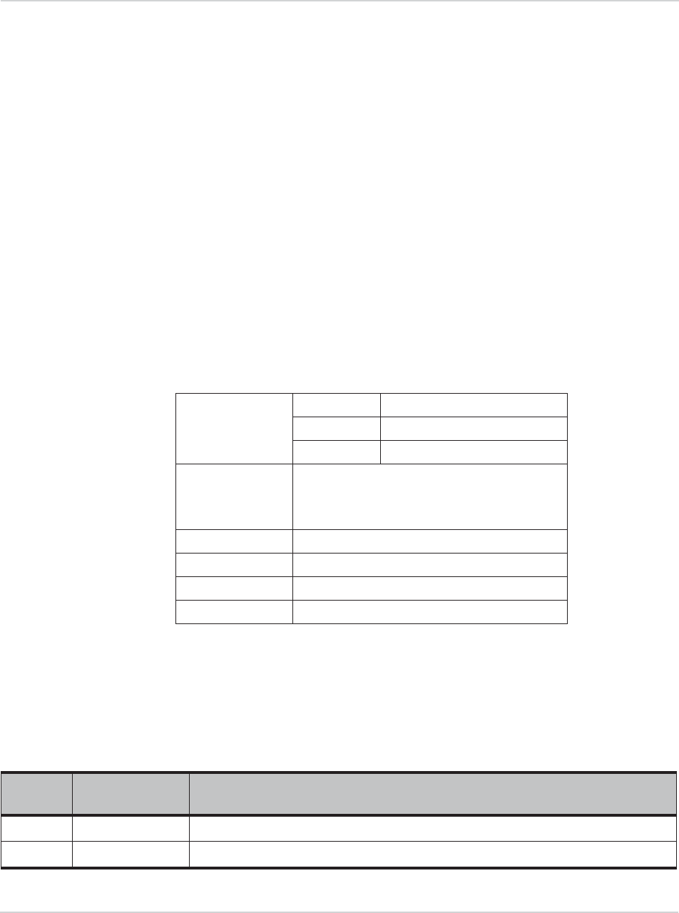
Tab l e 1 - 1 describes the connectors used to integrate the EM7355
Embedded Module into your host device.
Table 1-1: Required host-module connectors
Connector type Description
RF cables •Mate with M.2-spec connectors
•Three connector jacks
EDGE (67 pin) •Slot B compatible — Per the M.2 standard (PCI Express NGFF
(M.2) Electromechanical Specification Revision 0.7), a generic
75 pin position EDGE connector on the motherboard uses a
mechanical key to mate with the 67 pin notched module
connector.
•Manufacturers include LOTES (part #APCI0018-P001A01),
Kyocera, JAE, Tyco, and Longwell.
SIM •Industry-standard connector.

Hardware Integration Guide
8 Proprietary and Confidential - Contents subject to change 4112880

Rev 2 Feb.13 Proprietary and Confidential - Contents subject to change 9
2
2: Power
Power supply
The host provides power to the EM7355 through multiple power and
ground pins. The host must provide safe and continuous power (via
battery or a regulated power supply) at all times; the module does not
have an independent power supply, or protection circuits to guard
against electrical issues.
For detailed pinout and voltage / current requirements of this module,
see the AirPrime EM7355 Product Technical Specification &
Customer Design Guidelines.
Module power states
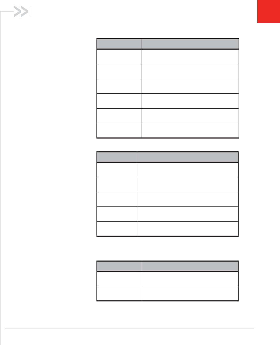
The module has five power states, as described in Ta bl e 2 - 1 .
Table 2-1: Module power states
State Details
Host is powered
Module is powered
USB interface active
RF enabled
Normal
(Default
state)
•Module is active
•Default state. Occurs when VCC is first applied, Full_Card_Power_Off# is
deasserted (pulled high), and W_DISABLE#1 is deasserted
•Module is capable of placing / receiving calls, or establishing data connections on the
wireless network
•Current consumption is affected by several factors, including:
•Radio band being used
•Transmit power
•Receive gain settings
•Data rate
Low power
(‘Airplane
mode’)
•Module is active
•Module enters this state:
•Under host interface control:
·Host issues AT+CFUN=0 ([1] AT Command Set for User Equipment (UE)
(Release 6) (Doc# 3GPP TS 27.007))), or
·Host asserts W_DISABLE#1, after AT!PCOFFEN=0 has been issued.
•Automatically, when critical temperature or voltage trigger limits have been
reached))

Hardware Integration Guide
10 Proprietary and Confidential - Contents subject to change 4112880
Sleep •Normal state of module between calls or data connections
•Module cycles between wake (polling the network) and sleep, at network provider-
determined interval.
Off •Host keeps module powered off by asserting Full_Card_Power_Off# (signal pulled
low or left floating)
•Module draws minimal current
Disconnected •Host power source is disconnected from the module and all voltages associated with
the module are at 0 V.
Table 2-1: Module power states (Continued)
State Details
Host is powered
Module is powered
USB interface active
RF enabled
Rev 2 Feb.13 Proprietary and Confidential - Contents subject to change 11
3
3: RF Specifications
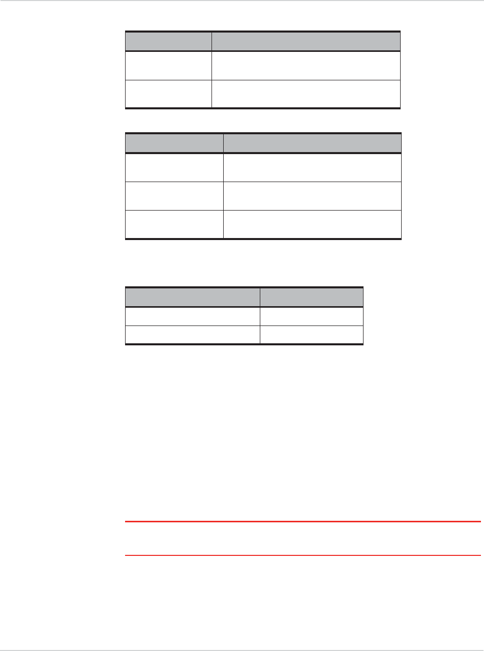
The EM7355 operates on the frequency bands listed below.
Table 3-1: LTE frequency band support
Band Frequencies
Band 2 Tx: 1850–1910 MHz
Rx: 1930–1990 MHz
Band 4 (AWS) Tx: 1710–1755 MHz
Rx: 2110–2155 MHz
Band 5 Tx: 824–849 MHz
Rx: 869–894 MHz
Band 13 Tx: 777–787 MHz
Rx: 746–756 MHz
Band 17 Tx: 704–716 MHz
Rx: 734–746 MHz
Band 25 Tx: 1850–1915 MHz
Rx: 1930–1995 MHz
Table 3-2: WCDMA frequency band support1
1. WCDMA channel spacing is 5 MHz, but this can be adjusted to
optimize performance in a particular deployment scenario.
Band Frequencies
Band 1
WCDMA 2100
Tx: 1920–1980 MHz
Rx: 2110–2170 MHz
Band 2
WCDMA 1900
Tx: 1850–1910 MHz
Rx: 1930–1990 MHz
Band 4
AWS 1700/2100
Tx: 1710–1755 MHz
Rx: 2110–2155 MHz
Band 5
WCDMA 850
Tx: 824–849 MHz
Rx: 869–894 MHz
Band 8
WCDMA 900
Tx: 880–915 MHz
Rx: 925–960 MHz
Table 3-3: GSM frequency band support
Band Frequencies
GSM 850 Tx: 824–849 MHz
Rx: 869–894 MHz
EGSM 900 Tx: 880–915 MHz
Rx: 925–960 MHz
Hardware Integration Guide
12 Proprietary and Confidential - Contents subject to change 4112880
RF connections
When attaching antennas to the module:
•Use any of the following (or compatible) 2x2 mm
RF receptacle connectors to attach antennas to the module’s connection
points
•Match coaxial connections between the module and the antenna to 50 :.
•Minimize RF cable losses to the antenna; the recommended maximum cable
loss for antenna cabling is 0.5 dB.
•To ensure best thermal performance, if possible use the mounting hole to
attach (ground) the device to a metal chassis.
Note: If the antenna connection is shorted or open, the modem will not sustain permanent
damage.
Shielding
The module is fully shielded to protect against EMI and must not be removed.
GSM 1800 Tx: 1710–1785 MHz
Rx: 1805–1880 MHz
GSM 1900 Tx: 1850–1910 MHz
Rx: 1930–1990 MHz
Table 3-4: CDMA frequency band support
Band Frequencies
Band Class 0
(Cellular 800 MHz)
Tx: 824–849 MHz
Rx: 869–894 MHz
Band Class 1
(PCS)
Tx: 1850–1910 MHz
Rx: 1930–1990 MHz
Band Class 10
(Secondary 800 MHz)1Tx: 817–824 MHz
Rx: 862–869 MHz
1. BC10 subclasses 2 and 3 (system designator C and D) are sup-
ported
Table 3-5: GNSS frequency band support
Band Frequencies
Narrow-band GPS Rx: 1575.42 MHz
Wide-band GPS + GLONASS Rx: 1565–1606 MHz
Table 3-3: GSM frequency band support (Continued)
Band Frequencies

RF Specifications
Rev 2 Feb.13 Proprietary and Confidential - Contents subject to change 13
Antenna and cabling
When selecting the antenna and cable, it is critical to RF performance to match
antenna gain and cable loss.
Choosing the correct antenna and cabling
When matching antennas and cabling:
•The antenna (and associated circuitry) should have a nominal impedance of
50 : with a return loss of better than 10 dB across each frequency band of
operation.
•The system gain value affects both radiated power and regulatory (FCC, IC,
CE, etc.) test results.
Designing custom antennas
Consider the following points when designing custom antennas:
•A skilled RF engineer should do the development to ensure that the RF
performance is maintained.
•If both UMTS and CDMA modules will be installed in the same platform, you
may want to develop separate antennas for maximum performance.
Determining the antenna’s location
When deciding where to put the antennas:
•Antenna location may affect RF performance. Although the module is
shielded to prevent interference in most applications, the placement of the
antenna is still very important — if the host device is insufficiently shielded,
high levels of broadband or spurious noise can degrade the module’s perfor-
mance.
•Connecting cables between the module and the antenna must have 50 :
impedance. If the impedance of the module is mismatched, RF performance
is reduced significantly.
•Antenna cables should be routed, if possible, away from noise sources
(switching power supplies, LCD assemblies, etc.). If the cables are near the
noise sources, the noise may be coupled into the RF cable and into the
antenna.
Disabling the diversity antenna
•For LTE / UMTS bands, use the AT command
!RXDEN=0
to disable receive
diversity or
!RXDEN=1
to enable receive diversity.
•For CDMA bands, use the AT command
!DIVERSITY
to enable or disable
receive diversity.
Note: A diversity antenna is used to improve connection quality and reliability through
redundancy. Because two antennas may experience difference interference effects (signal
distortion, delay, etc.), when one antenna receives a degraded signal, the other may not be
similarly affected.

Hardware Integration Guide
14 Proprietary and Confidential - Contents subject to change 4112880
Ground connection
When connecting the module to system ground:
•Prevent noise leakage by establishing a very good ground connection to the
module through the host connector.
•Connect to system ground using the module’s mounting hole.
•Minimize ground noise leakage into the RF.
Depending on the host board design, noise could potentially be coupled to
the module from the host board. This is mainly an issue for host designs that
have signals traveling along the length of the module, or circuitry operating at
both ends of the module interconnects.
Interference and sensitivity
Several interference sources can affect the module’s RF performance
(RF desense). Common sources include power supply noise and device-
generated RF.
RF desense can be addressed through a combination of mitigation techniques
(Methods to mitigate decreased Rx performance on page 15) and radiated
sensitivity measurement (Radiated sensitivity measurement on page 16).
Note: The EM7355 is based on ZIF (Zero Intermediate Frequency) technologies. When
performing EMC (Electromagnetic Compatibility) tests, there are no IF (Intermediate
Frequency) components from the module to consider.
Interference from other wireless devices
Wireless devices operating inside the host device can cause interference that
affects the module.
To determine the most suitable locations for antennas on your host device,
evaluate each wireless device’s radio system, considering the following:
•Any harmonics, sub-harmonics, or cross-products of signals generated by
wireless devices that fall in the module’s Rx range may cause spurious
response, resulting in decreased Rx performance.
•The Tx power and corresponding broadband noise of other wireless devices
may overload or increase the noise floor of the module’s receiver, resulting in
Rx desense.
The severity of this interference depends on the closeness of the other antennas
to the module’s antenna. To determine suitable locations for each wireless
device’s antenna, thoroughly evaluate your host device’s design.
Host-generated RF interference
All electronic computing devices generate RF interference that can negatively
affect the receive sensitivity of the module.

RF Specifications
Rev 2 Feb.13 Proprietary and Confidential - Contents subject to change 15
Proximity of host electronics to the antenna in wireless devices can contribute to
decreased Rx performance. Components that are most likely to cause this
include:
•Microprocessor and memory
•Display panel and display drivers
•Switching-mode power supplies
Device-generated RF interference
The module can cause interference with other devices. Wireless devices such as
AirPrime embedded modules transmit in bursts (pulse transients) for set durations
(RF burst frequencies). Hearing aids and speakers convert these burst
frequencies into audible frequencies, resulting in audible noise.
Methods to mitigate decreased Rx performance
It is important to investigate sources of localized interference early in the design
cycle. To reduce the effect of device-generated RF on Rx performance:
•Put the antenna as far as possible from sources of interference. The
drawback is that the module may be less convenient to use.
•Shield the host device. The module itself is well shielded to avoid external
interference. However, the antenna cannot be shielded for obvious reasons.
In most instances, it is necessary to employ shielding on the components of
the host device (such as the main processor and parallel bus) that have the
highest RF emissions.
•Filter out unwanted high-order harmonic energy by using discrete filtering on
low frequency lines.
•Form shielding layers around high-speed clock traces by using multi-layer
PCBs.
•Route antenna cables away from noise sources.
Radiated Spurious Emissions (RSE)
When designing an antenna for use with AirPrime embedded modules, the host
device with an AirPrime embedded module must satisfy the radiated spurious
emission (RSE) test cases described in:
•(CDMA) Refer to CDMA standards for receive-only mode, and local
regulatory bodies for transmit mode (transmitter is operating).
•CE/ETSI EN 301 908 (WCDMA), test numbers 5.3.1 (‘Radiated Emissions
(UE)’)
•CE/ETSI EN 301 511 (GSM), test 5.2.16 (‘Radiated Spurious Emissions - MS
allocated a channel’). This test uses the procedure and requirement outlined
in 3GPP 51.010 (GSM) section 12.2.1 of the same test name.
Note that antenna impedance affects radiated emissions, which must be
compared against the conducted 50-ohm emissions baseline. (AirPrime
embedded modules meet the 50-ohm conducted emissions requirement.)

Hardware Integration Guide
16 Proprietary and Confidential - Contents subject to change 4112880
Note: GSM spurious emissions are most likely to have RSE issues, but in general, RSE
requirements must be met on all models with user-designed antennas.
Radiated sensitivity measurement
A wireless host device contains many noise sources that contribute to a reduction
in Rx performance.
To determine the extent of any receiver performance desensitization due to self-
generated noise in the host device, over-the-air (OTA) or radiated testing is
required. This testing can be performed by Sierra Wireless or you can use your
own OTA test chamber for in-house testing.

Rev 2 Feb.13 Proprietary and Confidential - Contents subject to change 17
4
4: Regulatory Compliance and Industry
Certifications
This module is designed to meet, and upon commercial release, will
meet the requirements of the following regulatory bodies and
regulations, where applicable:
•Federal Communications Commission (FCC) of the United States
•The Certification and Engineering Bureau of Industry Canada
(IC)
•The National Communications Commission (NCC) of Taiwan,
Republic of China
Upon commercial release, the following industry certifications will
have been obtained, where applicable:
•GCF-CC (For Verizon 2G / 3G approval)
•PTCRB
•CDG2
Additional certifications may be obtained upon customer request —
contact your Sierra Wireless account representative for details.
Additional testing and certification may be required for the end
product with an embedded EM7355 modem and are the
responsibility of the OEM. Sierra Wireless offers professional
services-based assistance to OEMs with the testing and certification
process, if required.
Important notice
Because of the nature of wireless communications, transmission and
reception of data can never be guaranteed. Data may be delayed,
corrupted (i.e., have errors) or be totally lost. Although significant
delays or losses of data are rare when wireless devices such as the
Sierra Wireless modem are used in a normal manner with a well-
constructed network, the Sierra Wireless modem should not be used
in situations where failure to transmit or receive data could result in
damage of any kind to the user or any other party, including but not
limited to personal injury, death, or loss of property. Sierra Wireless
and its affiliates accept no responsibility for damages of any kind
resulting from delays or errors in data transmitted or received using
the Sierra Wireless modem, or for failure of the Sierra Wireless
modem to transmit or receive such data.
Safety and hazards
Do not operate your EM7355 modem:
•In areas where blasting is in progress

Hardware Integration Guide
18 Proprietary and Confidential - Contents subject to change 4112880
•Where explosive atmospheres may be present including refuelling points, fuel
depots, and chemical plants
•Near medical equipment, life support equipment, or any equipment which
may be susceptible to any form of radio interference. In such areas, the
EM7355 modem MUST BE POWERED OFF. Otherwise, the EM7355 modem
can transmit signals that could interfere with this equipment.
In an aircraft, the EM7355 modem MUST BE POWERED OFF. Otherwise, the
EM7355 modem can transmit signals that could interfere with various onboard
systems and may be dangerous to the operation of the aircraft or disrupt the
cellular network. Use of a cellular phone in an aircraft is illegal in some
jurisdictions. Failure to observe this instruction may lead to suspension or denial
of cellular telephone services to the offender, or legal action or both.
Some airlines may permit the use of cellular phones while the aircraft is on the
ground and the door is open. The EM7355 modem may be used normally at this
time.
Important compliance information for
North American users
Note: Details are preliminary and subject to change.
The EM7355 modem has been granted modular approval for mobile applications.
Integrators may use the EM7355 modem in their final products without additional
FCC / IC (Industry Canada) certification if they meet the following conditions.
Otherwise, additional FCC / IC approvals must be obtained.
1. At least 20 cm separation distance between the antenna and the user’s body
must be maintained at all times.
2. To comply with FCC / IC regulations limiting both maximum RF output power
and human exposure to RF radiation, the maximum antenna gain including
cable loss in a mobile-only exposure condition must not exceed:
·6.5 dBi in Cellular band
·3.0 dBi in PCS band
·3.0 dBi in LTE Band 2
·6.0 dBi in LTE Band 4
·6.5 dBi in LTE Band 5
·9.0 dBi in LTE Band 13 (Note: LTE Band 13 is not permitted in Canada.)
·9.0 dBi in LTE Band 17 (Note: LTE Band 17 is not permitted in Canada.)
·3.0 dBi in LTE Band 25

Regulatory Compliance and Industry Certifications
Rev 2 Feb.13 Proprietary and Confidential - Contents subject to change 19
·The output power and antenna gain must not exceed the limits and configu-
rations stipulated in the following table.
3.A label must be affixed to the outside of the end product into which the
EM7355 modem is incorporated, with a statement similar to the following:
· This device contains FCC ID: S9E-EM7355
Contains transmitter module IC: $(0 where $(0
is the module’s certification number.
4.A user manual with the end product must clearly indicate the operating
requirements and conditions that must be observed to ensure compliance
with current FCC / IC RF exposure guidelines.
Device Technology Band Frequency
(MHz)
Maximum
conducted power
(dBm)
Maximum
antenna gain
(dBi)
EM7355
Embedded
Module
LTE 21850–1910 24 3
41710–1755 24 6
5824–849 24 3
13 777–787 24 6
17 704–716 24 6
25 1850–1915 24 3
UMTS 21850–1910 24 3
41710–1755 24 6
5824–849 24 3
GSM 850 824–849 33 3
1900 1850–1910 30 3
CDMA BC0 824–849 25 3
BC1 1850–1910 25 3
BC10 817–824 25 3
Collocated
transmitters1WLAN 2400–2500 29 5.0
5150–5850 29 5.0
WiMAX 2300–2400 29 5.0
2500–2700 29 5.0
3300–3800 29 5.0
BT 2400–2500 15 5.0
1. Valid collocated transmitter combinations: WLAN+BT; WiMAX+BT.
(WLAN+WiMAX+BT is not permitted.)

Hardware Integration Guide
20 Proprietary and Confidential - Contents subject to change 4112880
The end product with an embedded EM7355 modem may also need to pass the
FCC Part 15 unintentional emission testing requirements and be properly
authorized per FCC Part 15.
Note:
If this module is intended for use in a portable device, you are responsible
for separate approval to satisfy the SAR requirements of FCC Part 2.1093 and IC
RSS-102.
The EM7355 modem may transmit simultaneously with other collocated radio
transmitters within a host device, provided the following conditions are met:·
*Each collocated radio transmitter has been certfied by FCC / IC for mobile
application.·
*At least 20 cm separation distance between the antennas of the collocated
transmitters and the user’s body must be maintained at all times.
*Radio Frequency (RF) Exposure Information
The radiated output power of the Wireless Device is below the Industry Canada (IC)
radio frequency exposure limits. The Wireless Device should be used in such a
manner such that the potential for human contact during normal operation is minimized.
This device has also been evaluated and shown compliant with the IC RF Exposure
limits under mobile exposure conditions. (antennas are greater than 20cm from a person's body).
*Informations concernant l'exposition aux fréquences radio (RF)
La puissance de sortie émise par l’appareil de sans fil est inférieure à la limite d'exposition
aux fréquences radio d'Industry Canada (IC). Utilisez l’appareil de sans fil de façon à
minimiser les contacts humains lors du fonctionnement normal.
Ce périphérique a également été évalué et démontré conforme aux limites d'exposition
aux RF d'IC dans des conditions d'exposition à des appareils mobiles (les antennes se
situent à moins de 20 cm du corps d'une personne).

Rev 2 Feb.13 Proprietary and Confidential - Contents subject to change 21
5
5: Acronyms
Table 5-1: Acronyms and definitions
Acronym or term Definition
1xEV-DO Single Carrier (1X) EVolution – Data Only. A high-speed standard for cellular
packet data communications.
Supports Internet connections with data rates up to 3.1 Mbps (downlink from the
network) and 1.8 Mbps (uplink to the network). Average data rates are roughly: for
Rev. A: 600 1300 kbps (downlink from the network) and 300 400 kbps (uplink to
the network); for Rev. 0: 400 700 kbps (downlink from the network) and 40 80
kbps (uplink to the network). Actual speed depends on the network conditions.
Compare to 1X.
1X Single Carrier (1X) Radio Transmission Technology. A high-speed standard for
cellular packet data communications.
Supports Internet connections with data rates up to 153 kbps (simultaneously in
each direction—downlink and uplink). Actual speed depends on the network
conditions. Compare to 1xEV-DO.
3GPP 3rd Generation Partnership Project
8PSK Octagonal Phase Shift Keying
AGC Automatic Gain Control
A-GPS Assisted GPS
A-GNSS Assisted GNSS
API Application Programming Interface
BER Bit Error Rate—A measure of receive sensitivity
BLER Block Error Rate
bluetooth Wireless protocol for data exchange over short distances
CAIT CDMA Air Interface Tool
CDG CDMA Development Group—a consortium of companies that develop and
promote the products and services for CDMA wireless systems.
CDMA Code Division Multiple Access.
A wideband spread spectrum technique used in digital cellular, personal
communications services, and other wireless networks. Wide channels (1.25
MHz) are obtained through spread spectrum transmissions, thus allowing many
active users to share the same channel. Each user is assigned a unique digital
code, which differentiates the individual conversations on the same channel.
CQI Channel Quality Indication
COM Communication port
CS Circuit-switched
CW Continuous waveform

Hardware Integration Guide
22 Proprietary and Confidential - Contents subject to change 4112880
dB Decibel = 10 x log10 (P1/P2)
P1 is calculated power; P2 is reference power
Decibel = 20 x log10 (V1/V2)
V1 is calculated voltage, V2 is reference voltage
dBm A logarithmic (base 10) measure of relative power (dB for decibels); relative to
milliwatts (m). A dBm value will be 30 units (1000 times) larger (less negative)
than a dBW value, because of the difference in scale (milliwatts vs. watts).
DC-HSPA+ Dual Carrier HSPA+
DCS Digital Cellular System
A cellular communication infrastructure that uses the 1.8 GHz radio spectrum.
DL Downlink (network to mobile)
DUN Dial-Up Networking
DRX Discontinuous Reception
DSM Distributed Shared Memory
DUT Device Under Test
EDGE Enhanced Data rates for GSM Evolution
eHRPD Evolved High Rate Packet Data—Enhances traditional 1xEV-DO to enable LTE
to CDMA handover.
EIRP Effective (or Equivalent) Isotropic Radiated Power
EMC Electromagnetic Compatibility
EMI Electromagnetic Interference
ERP Effective Radiated Power
ESD Electrostatic Discharge
FCC Federal Communications Commission
The U.S. federal agency that is responsible for interstate and foreign
communications. The FCC regulates commercial and private radio spectrum
management, sets rates for communications services, determines standards for
equipment, and controls broadcast licensing. Consult www.fcc.gov.
FDMA Frequency Division Multiple Access
FER Frame Error Rate—A measure of receive sensitivity.
firmware Software stored in ROM or EEPROM; essential programs that remain even when
the system is turned off. Firmware is easier to change than hardware but more
permanent than software stored on disk.
FOTA Firmware Over The Air—Technology used to download firmware upgrades
directly from the service provider, over the air.
FOV Field Of View
Table 5-1: Acronyms and definitions (Continued)
Acronym or term Definition

Acronyms
Rev 2 Feb.13 Proprietary and Confidential - Contents subject to change 23
FSN Factory Serial Number—A unique serial number assigned to the mini card during
manufacturing.
GCF Global Certification Forum
GLONASS Global Navigation Satellite System—A Russian system that uses a series of 24
satellites in middle circular orbit to provide navigational data.
GMSK Gaussian Minimum Shift Keying modulation
GNSS Global Navigation Satellite Systems (GPS plus GLONASS)
GPRS General Packet Radio Service
GPS Global Positioning System
An American system that uses a series of 24 satellites in middle circular orbit to
provide navigational data.
GSM Global System for Mobile Communications
Host The device into which an embedded module is integrated
HSDPA High Speed Downlink Packet Access
HSPA+ Enhanced HSPA, as defined in 3GPP Release 7 and beyond
HSUPA High Speed Uplink Packet Access
Hz Hertz = 1 cycle/second
IC Industry Canada
IF Intermediate Frequency
IMEI International Mobile Equipment Identity
IMS IP Multimedia Subsystem—Architectural framework for delivering IP multimedia
services.
inrush current Peak current drawn when a device is connected or powered on
inter-RAT Radio Access Technology
IOT Interoperability Testing
IS Interim Standard.
After receiving industry consensus, the TIA forwards the standard to ANSI for
approval.
IS-2000 3G radio standards for voice and data (CDMA only)
IS-95 2G radio standards targeted for voice (cdmaONE)
LED Light Emitting Diode.
A semiconductor diode that emits visible or infrared light.
LHCP Left-Hand Circular Polarized
LNA Low Noise Amplifier
Table 5-1: Acronyms and definitions (Continued)
Acronym or term Definition

Hardware Integration Guide
24 Proprietary and Confidential - Contents subject to change 4112880
LPM Low Power Mode
LPT Line Print Terminal
LTE Long Term Evolution—a high-performance air interface for cellular mobile
communication systems.
MCS Modulation and Coding Scheme
MHz Megahertz = 10e6 Hz
MEID Mobile Equipment Identifier—The unique second-generation serial number
assigned to the minicard for use on the wireless network.
MIMO Multiple Input Multiple Output—wireless antenna technology that uses multiple
antennas at both transmitter and receiver side. This improves performance.
NAS / AS Network Access Server
NC No Connect
NIC Network Interface Card
NMEA National Marine Electronics Association
OEM Original Equipment Manufacturer—a company that manufactures a product and
sells it to a reseller.
OFDMA Orthogonal Frequency Division Multiple Access
OMA DM Open Mobile Alliance Device Management—A device management protocol.
OTA ‘Over the air’ (or radiated through the antenna)
PA Power Amplifier
packet A short, fixed-length block of data, including a header, that is transmitted as a unit
in a communications network.
PCB Printed Circuit Board
PCS Personal Communication System
A cellular communication infrastructure that uses the 1.9 GHz radio spectrum.
PDN Packet Data Network
PMI Pre-coding Matrix Index
PSS Primary synchronisation signal
PST Product Support Tools
PTCRB PCS Type Certification Review Board
QAM Quadrature Amplitude Modulation.
This form of modulation uses amplitude, frequency, and phase to transfer data on
the carrier wave.
QMI Qualcomm MSM/Modem Interface
Table 5-1: Acronyms and definitions (Continued)
Acronym or term Definition

Acronyms
Rev 2 Feb.13 Proprietary and Confidential - Contents subject to change 25
QOS Quality of Service
QPSK Quadrature Phase-Shift Keying
QPST Qualcomm Product Support Tools
RAT Radio Access Technology
RF Radio Frequency
RI Ring Indicator
roaming A cellular subscriber is in an area where service is obtained from a cellular service
provider that is not the subscriber’s provider.
RSE Radiated Spurious Emissions
RSSI Received Signal Strength Indication
SDK Software Development Kit
SED Smart Error Detection
Sensitivity
(Audio)
Measure of lowest power signal that the receiver can measure.
Sensitivity (RF) Measure of lowest power signal at the receiver input that can provide a prescribed
BER/BLER/SNR value at the receiver output.
SG An LTE signaling interface for SMS (“SMS over SGs”)
SIB System Information Block
SIM Subscriber Identity Module. Also referred to as USIM or UICC.
SIMO Single Input Multiple Output—smart antenna technology that uses a single
antenna at the transmitter side and multiple antennas at the receiver side. This
improves performance and security.
SISO Single Input Single Output—antenna technology that uses a single antenna at
both the transmitter side and the receiver side.
SKU Stock Keeping Unit—identifies an inventory item: a unique code, consisting of
numbers or letters and numbers, assigned to a product by a retailer for purposes
of identification and inventory control.
SMS Short Message Service.
A feature that allows users of a wireless device on a wireless network to receive
or transmit short electronic alphanumeric messages (up to 160 characters,
depending on the service provider).
S/N Signal-to-noise (ratio)
SNR Signal-to-Noise Ratio
SOF Start of Frame—A USB function.
SSS Secondary synchronisation signal.
Table 5-1: Acronyms and definitions (Continued)
Acronym or term Definition

Hardware Integration Guide
26 Proprietary and Confidential - Contents subject to change 4112880
SUPL Secure User Plane Location
TIA/EIA Telecommunications Industry Association / Electronics Industry Association.
A standards setting trade organization, whose members provide communications
and information technology products, systems, distribution services and
professional services in the United States and around the world. Consult
www.tiaonline.org.
TIS Total Isotropic Sensitivity
TRP Total Radiated Power
UDK Universal Development Kit (for PCI Express Mini Cards)
UE User Equipment
UICC Universal Integrated Circuit Card (Also referred to as a SIM card.)
UL Uplink (mobile to network)
UMTS Universal Mobile Telecommunications System
USB Universal Serial Bus
USIM Universal Subscriber Identity Module (UMTS)
VCC Supply voltage
VSWR Voltage Standing Wave Ratio
WAN Wide Area Network
WCDMA Wideband Code Division Multiple Access (also referred to as UMTS)
WLAN Wireless Local Area Network
ZIF Zero Intermediate Frequency
Table 5-1: Acronyms and definitions (Continued)
Acronym or term Definition

Rev 2 Feb.13 Proprietary and Confidential - Contents subject to change 27
Index
A
accessories, 7
acronyms and definitions, 21– 26
antenna
connection considerations, 12
custom, design, 13
diversity antenna, disabling, 13
limit, matching coaxial connections, 12
location, considerations, 13
matching, considerations, 13
maximum cable loss, 12
routing, 13
approvals, regulatory and industry, 17
B
bands supported, RF
CDMA, 12
GSM, 11, 12
LTE, 11
WCDMA, 11
C
cable loss
antenna, maximum, 12
CDMA
frequency band support, 12
connection
grounding, 14
connectors, required
host-module, 7
D
desense. See RF
diversity antenna
disabling, 13
E
EDGE
connector, required, 7
F
filtering, RF desense, 15
frequency band support
CDMA, 12
GSM, 11, 12
LTE, 11
WCDMA, 11
G
gain
maximum, 18
grounding
connection considerations, 14
GSM
frequency band support, 11, 12
I
impedance
module–antenna, 13
industry approvals, 17
interference
device generated, 15
host-generated, 14
wireless devices, 14
L
LTE
frequency band support, 11
N
noise
leakage, minimizing, 14
P
PCB
multi-layer, shielding for RF desense, 15
R
radiated sensitivity measurement, 16
radiated spurious emissions, 15
regulatory approvals, 17
regulatory information, 17– 20
FCC, 18
limitation of liability, 17
safety and hazards, 17

Hardware Integration Guide
28 Proprietary and Confidential - Contents subject to change 4112880
RF
antenna cable loss, maximum, 12
antenna connection, considerations, 12
connectors, required, 7
desense
device-generated, 14
harmonic energy, filtering, 15
mitigation suggestions, 15
shielding suggestions, 15
interference
other devices, 15
wireless devices, 14
RF bands supported
CDMA, 12
GSM, 11, 12
LTE, 11
WCDMA, 11
RF specifications, 11– 16
RSE, 15
S
sensitivity
radiated measurement, overview, 16
shielding
module, compliance, 12
reducing RF desense, 15
SIM
connector, required, 7
specifications
RF, 11– 16
W
WCDMA
frequency band support, 11
Z
ZIF (Zero Intermediate Frequency), 14