Troybilt 13AX60TG766 User Manual TRACTOR Manuals And Guides L0602167
TROYBILT Lawn, Tractor Manual L0602167 TROYBILT Lawn, Tractor Owner's Manual, TROYBILT Lawn, Tractor installation guides
User Manual: Troybilt 13AX60TG766 13AX60TG766 TROYBILT TRACTOR - Manuals and Guides View the owners manual for your TROYBILT TRACTOR #13AX60TG766. Home:Lawn & Garden Parts:Troybilt Parts:Troybilt TRACTOR Manual
Open the PDF directly: View PDF ![]() .
.
Page Count: 48

Automatic Lawn Tractor- Super Bronco TM(Model 60TG)
READ SAFETY RULES AND mNSTRUCTmONS CAREFULLY BEFORE OPERATION
Warning: This unitis equippedwithan internalcombustionengineandshouldnot beusedon or nearany unimprovedforest-covered,brush=
coveredor grass=coveredlandunlessthe engine'sexhaustsystemis equippedwitha sparkarrestermeetingapplicablelocalor state laws(if any),
If a sparkarresteris used,it shouldbemaintainedineffectiveworkingorderby the operator,Inthe Stateof Californiathe aboveis requiredbylaw
(Section4442of the CaliforniaPublicResourcesCode),Otherstatesmayhavesimilarlaws,Federallawsapplyonfederallands,A sparkarrester
for the muffleris availablethroughyournearestengineauthorizedservicedealeror contactthe servicedepartment,RO,Box361131Cleveland,
Ohio44136=0019,
FORMNO,770=10490H
PRINTEDIN U,S,A Troy-Bilt LLC, P.O. BOX 361131 CLEVELAND, OHIO 44136-0019 1/03/2006
This Operator's Manua_ is an important part of your new lawn tractor, mtwH_ he_p you assemble,
prepare and maintain the unit for best performance. P_ease read and understand what it says.
Table of Contents
Slope Gauge ....................................................... 3
Safe Operation Practices ................................... 4
Setting Up Your Lawn Tractor ............................ 8
Operating Your Lawn Tractor ........................... 10
Adjusting Your Lawn Tractor ............................ 18
Maintaining Your Lawn Tractor ........................ 20
Off-Season Storage /Attachments ................. 26
Safety Labels .................................................... 27
TrouMe Shooting .............................................. 28
Parts List ........................................................... 30
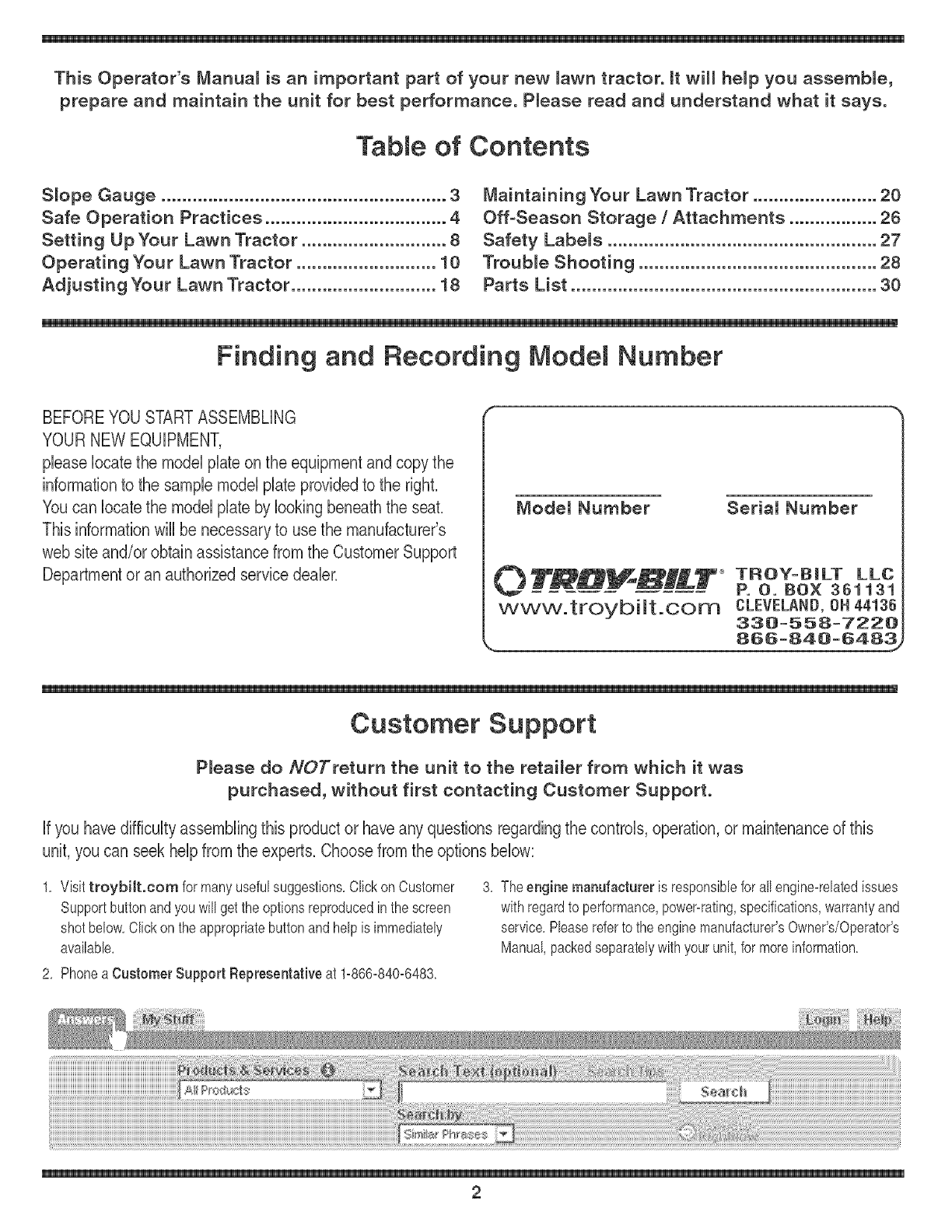
Finding and Recording Model Number
BEFOREYOU STARTASSEMBLING
YOUR NEW EQUIPMENT,
please locatethe model plate on the equipmentand copy the
informationto the sample model plate providedto the righL
Youcan locatethe model plate by looking beneath the seal
This information will be necessaryto use the manufacturer's
web site and/or obtain assistance from the Customer Support
Department or an authorizedservice dealer.
Modem Number Seriam Number
0 TR#_H_--T_ TROY=BiLT LLC
P. O. BOX 361131
www.troybiit.com CLEVELAND, ON 44136
338=558=7228
,, 856=848=6483_
Customer Support
P_ease do NOTreturn the unitto the retai_er from which it was
purchased, without first contacting Customer Support.
if you havedifficulty assemblingthis product or haveany questions regarding the controls, operation,or maintenance of this
unit, you can seek helpfrom the expert& Choose from the options below:
1, Visittroybilt.com for manyusefulsuggestions,Clickon Customer
Supportbuttonandyouwill get the optionsreproducedin thescreen
shotbelow,CIbk onthe appropriatebuttonandhelpis immediately
availabb,
3, The engine manufacturer is responsibbforall engine=relatedissues
with regardto performance,power=rating,specifications,warrantyand
service,Phase referto the enginemanufacturer'sOwner's/Operator's
Manual,packedseparatelywithyour unit,for moreinformation,
2, Phonea Customer Support Representative at 1=866-840=6483,

your lawn moweron such slopes.
/
/
/
/
o
/
/
t
o
w_
WARNING
Do not mowon inclines
with a dope in excess
of 15 degrees (a rise
of approximately
2-"
feet). A riding r
could overturnand
cause serious injury.
if operatinga walb
behind mower on such
a dope, it is extremely
footing and you could
dip, resultingin serious
injury.
Operate RiDiNG
mowers up and down
dopes, neveracross
the face of dopes.
Operate
WALK-BEHIND
mowers across the
face of dopes, never
up and down slopes.
\
3

_i i _ i _i _ i _ iii _ _
DANGER: This machine was built to be operated according to the rubs for safeoperation in this
manuakAs with any type of power equipment, carelessnessor error on the part of the operator can
S ale result in serious injury.This machineis capable of amputating hands and feet and throwing objects.
Failureto observe the following safetyinstructionscould result in serious injury or death.
instructionswhich, if
notfollowed, could
endangerthe personal
safetyand/or property
of yourself and others.
Read andfobow all
instructionsin this man=
ual before attemptingto
operatethis machine.
Failureto complywith
When you see this
symbol.
H EED ITS WARNING
Your
Responsibility
Restrictthe use
of this power machine
to personswho read.
understand
and follow the warnings
and instructions
in this manual
Children
1. Tragicaccidentscan occurif the operatoris not
abrt tothe presenceof children.Childrenareoften
attractedto the machineandthe mowingactivity.
Theydo not understandthe dangers.Neverassume
thatchildrenwill remainwhereyou lastsawthem.
a. Keepchildrenout of the mowingareaandin
watchfulcare of a responsibleadult otherthan
the operator.
b. Bealert andturn machineoff if a childenters
the area.
c. Beforeandwhile backing,lookbehindand
downfor smallchildren.
d. Nevercarrychildren,evenwiththe blade(s)
shutoff.Theymayfalloffandbeseriously
iniuredor interferewithsafemachineoperation.
e. Useextremecarewhenapproachingblind
corners,doorways,shrubs,treesor other
objectsthatmayblockyourvisionof a child
who mayruninto the machine.
f. To avoid back-overaccidents, always
disengage the cutting blade(s) before
shifting into Reverse.If equipped, the
"ReverseCaution Mode" should not be
used when children or others are around.
g. Keepchildrenawayfromhotor running
engines.Theycansuffer burnsfroma hot
muffler.
h. Removekeywhen machineis unattendedto
preventunauthorizedoperation.
2. Neverallowchildrenunder14yearsoldto operate
the machine.Children14}'earsoldandovershould
readandunderstandthe operationinstructionsand
safetyrubs inthis manualandshouldbetrainedand
supervisedbya parent.
Operation
Safe Handlingof Gasoline:
1. Toavoid personal injuryor property damage use
extreme care in handlinggasoline. Gasoline is
extremely flammable and the vapors areexplo-
sive. Seriouspersonaliniurycanoccurwhengasoline
is spilledonyourselfor yourclotheswhichcan ignite.
Washyourskinandchangeclothesimmediately.
a. Useonlyan approvedgasolinecontainer.
b. Neverfill containersinsidea vehbb or ona
truckor trailerbedwitha plastb liner.Always
placecontainerson the groundawayfrom
yourvehble beforefilling.
c. When practbal, removegas-powered
equipmentfromthe truck ortrailerand refuelit
onthe ground.Ifthis is not possibb, then
refuelsuchequipmentona trailerwitha
portabb container,ratherthan fromagasoline
dispensernozzb.
d. Keepthe nozzb in contactwiththe rimof
the fueltankor containeropeningat all
timesuntilfuelingis complete.Donot usea
nozzleIocbopendevice.
e. Extinguishallcigarettes,cigars,pipesand
othersourcesof ignition.
f. Neverfuel machineindoors.
g. Neverremovegas cap oraddfuel whilethe
engineis hot or running.Mow engineto cool
at bast twominutesbeforerefueling.
h. Neveroverfill fuel tank.Fill tankto nomore
than1/2inchbelowbottomof filbr neckto
allowspacefor fuel expansion.
i. Replacegasolinecapandtightensecurely.
i. If gasolineis spilled,wipe it off the engine
andequipment.Moveunitto anotherarea.
Wait5 minutesbeforestartingthe engine.
k. To reducefire hazards,keepmachinefreeof
grass,leaves,orother debrisbuild-up.Clean
upoil orfuel spillageand removeany fuel
soakeddebris.
I. Neverstorethe machineorfuel container
insidewherethere is anopenflame,spark
or pilotlightas on a waterheater,space
heater,furnace,clothesdryeror othergas
appliances.
m. Allowa machineto cool at bast fiveminutes
beforestoring.
4

GeneralOperation:
1. Read,understand,andfollowall instructionsonthe
machineandinthe manual(s)beforeattemptingto
assembleandoperate.Keepthismanualina safe
placefor futureandregularreferenceandforordering
replacementparts.
2. Befamiliarwithall controlsandtheirproperoperation.
Knowhow to stopthe machineanddisengagethem
quickly.
3. Neverallowchildrenunder14yearsold to operate
this machine.Children14yearsold andovershould
readandunderstandthe operationinstructionsand
safetyrubs in thismanualandshouldbetrainedand
supervisedby aparent.
4. Neverallowadultsto operatethis machinewithout
properinstruction.
5. To helpavoid bladecontactora thrownobiectiniury,
keepbystanders,helpers,childrenand petsat bast
75 feetfromthe machinewhileit is inoperation.8top
machineif anyoneentersthe area.
6. Thoroughlyinspecttheareawherethe equipmentis to
beused.Removeallstones,sticks,wire,bones,toys,
andotherforeignobiectswhichcould bepickedup
andthrownbythe blade(s).Thrownobiectscancause
seriouspersonaliniury.
7, Planyourmowingpatternto avoiddischargeof
materialtowardroads,sidewalks,bystandersandthe
like.Also,avoiddischargingmaterialagainsta wall or
obstructionwhichmaycausedischargedmaterialto
ricochetbacktowardthe operator.
8. Alwayswearsafetyglassesor safetygogglesduring
operationandwhile performingan adiustmentor
repairto protectyour eyes.Thrownobiectswhich
ricochetcan causeseriousiniuryto the eyes.
9. Wearsturdy,rough-sobdworkshoesandclose-fitting
slacksandshirts.Loosefittingclothesandiewelry
can becaughtinmovabbparts. Neveroperatethis
machinein barefeetor sandals.
10.Beawareof the mowerandattachmentdischarge
directionanddo notpoint it at anyone.Do notoperate
the mowerwithoutthe dischargecoverorentiregrass
catcherin itsproperplace.
11.Do notput handsor feetnearrotatingpartsor under
the cuttingdeck.Contactwiththe blade(s)can
amputatehandsandfeet.
12.Amissingor damageddischargecovercan cause
bladecontactor thrownobiectiniuries.
13.8topthe blade(s)whencrossinggraveldrives,walks,
or roadsandwhilenot cuttinggrass.
14.Watchfor trafficwhenoperatingnearor crossing
roadways.Thismachineis not intendedfor useon
anypublic roadway.
15.Do notoperatethe machinewhileunderthe influ-
enceof alcoholordrugs.
16.Mowonly in daylightor goodartificiallight.
17,Nevercarrypassengers.
18.Disengageblade(s)beforeshiftinginto reverse.
Backupslowly.Alwayslookdownandbehindbefore
andwhilebackingto avoida back-overaccident.
19.Slowdownbeforeturning.Operatethe machine
smoothly.Avoiderraticoperationandexcessive
instructionswh ch. if
not followed,could
endanger the personal
safety and/or property
of yourself and others.
Read and follow all
instructionsin this man-
ual before attempting to
operatethis machine.
these instructions may
result in personal injury.
When you see this
symbol.
HEED iTS WARNING
Your
Responsibility
Restrictthe use
dthis power machine
to personswho read,
understand
and followthe warninas
and instructions
in this manual
5
21.Neverleavea runningmachineunattended.Always
turnoff blade(s),placetransmissionin neutral,set
parkingbrake,stopengineand removekeybefore
dismounting.
22.Useextracare whenloadingor unloadingthe
machineintoa trailerortruck.Thisunitshould not
bedrivenupor downramp(s),becausethe unit
couldtip over,causingseriouspersonaliniury.The
unit mustbepushedmanuallyonramp(s)to loador
unloadproperly.
23.Mufflerandenginebecomehotandcan causea
burn.Do nottouch.
24.Checkoverheadclearancescarefullybeforedriving
underlowhangingtreebranches,wires,dooropen-
ingsetc. wheretheoperatormaybe struckor pulled
fromthe unit,whichcouldresultinseriousiniury.
25.Disengageallattachmentclutches,depressthe
brakepedalcompbtelyandshift into neutralbefore
attemptingto startengine.
26.Yourmachineis designedto cutnormalresidential
grassof aheightno morethan 10".Do notattemptto
mowthroughunusuallytall,dry grass(e.g.,pasture)
or pilesof dry leaves.Drygrassor leavesmay
contactthe engineexhaustand/orbuildup onthe
mowerdeckpresentinga poten%l fire hazard.
27.Useonlyaccessoriesandattachmentsapprovedfor
thismachineby the machinemanufacturer.Read,
understandandfollowall instructionsprovidedwith
the approvedaccessoryor attachment.
28.Dataindicatesthatoperators,age60 yearsand
above,areinvolvedin a largepercentageof riding
mower-relatediniuries.Theseoperatorsshould
evaluatetheirabilityto operatetheridingmower
safelyenoughto protectthemselvesandothersfrom
seriousiniury.
29.If situationsoccur whicharenot coveredinthis
manual,usecareandgoodiudgment.Contactyour
customerservicerepresentativefor assistance.
WARNING
This symbol points
speed. }
20.Dbengageblade(s),setparkingbrake,stopengine
andwaituntilthe blade(s)cometo acompletestop
beforeremovinggrasscatcher,emptyinggrass,
uncloggingchute,removingany grassor debris,or
makinganyadiustments.

Slope Operation:
Slopesarea majorfactorrelatedto lossof controland
tip-overaccidentswhichcan resultin severeinjury or
death,All slopesrequireextracaution,if you cannot
backupthe slopeor if youfeel uneasyonit, do notmow
it,
Foryour safety,usethe slopegaugeincludedas partof
thismanualto measureslopesbeforeoperatingthisunit
ona slopedor hillyarea,if the slopeis greaterthan 15
;_,_ degreesas shownonthe slopegauge,do notoperate
,, thisunit onthatareaorseriousinjurycouldresult,
uperal:lon Do:
1, Mowupanddownslopes,notacross,Exercise
racl:lces extremecautionwhenchangingdirectiononsbpes,
2, Watchfor hobs, ruts,bumps,rocks,or other hidden
objects,Uneventerraincouldoverturnthe machine,
out important safety
instructions which, if
not followed,could
endangerthe personal
safety and/or property
of yourself and others.
Readand follow all
instructionsin this man°
ual before attempting to
Tallgrasscan hideobstacbs,
3, Useslowspeed,Choosea low enoughspeed
settingso thatyouwill not haveto stoporshift while
onthe slope,Tiresmaylosetractiononslopeseven
thoughthe brakesarefunctioningproperly,Always
keepmachineingearwhengoingdownslopesto
takeadvantageof enginebrakingaction,
4, Followthe manufacturer'srecommendationsfor
wheelweightsorcounterweightsto improvestability,
5, Useextracarewithgrasscatchersor otherat-
tachments,Thesecanchangethe stabilityof the
machine,
6, Keepall movementon theslopesslowandgradual
Do not makesuddenchangesinspeedor direction,
Rapidengagementor brakingcouldcausethe front
of the machineto liftand rapidlyfib overbackwards
whichcouldcauseseriousinjury,
7, Avoidstartingor stoppingon a slope,If tireslose
traction,disengagethe blade(s)andproceedslowly
straightdownthe slope,
Do Not:
1, Do notturn onslopesunlessnecessary;then,turn
slowlyandgraduallydownhill,if possibb,
2, Do not mowneardrop-offs,ditchesor embankments,
The mowercouldsuddenlyturnoverif awheel is over
the edgeof acliff,ditch,or if anedgecavesin,
3, Do nottry to staNlizethe machineby puttingyourfoot
onthe ground,
4, Do not usea grasscatcheronsteepslopes,
5, Do not mowonwetgrass,Reducedtractioncould
causesliding,
6, Do notshift to neutralandcoastdownhill Over-speed-
ingmaycausethe operatorto lose controlof the
machineresultingin seriousinjuryordeath,
7, Do nottow heavypullbehindattachments(e,g,loaded
dumpcart, lawnroller,etc,)on slopesgreaterthan
5 degrees,Whengoingdown hill,the extraweight
tendsto pushthetractorand maycauseyou to loose
control (e,g,tractormayspeedup, brakingandsteer-
ingabilityarereduced,attachmentmayjack-knifeand
causetractorto overturn),
Towing:
1, Towonlywitha machinethathasa hitchdesignedfor
towing,Do not attachtowedequipmentexceptat the
hitchpoint,
2, Followthe manufacturersrecommendationfor weight
limitsfor towedequipmentandtowingonslopes,
3, Neverallowchildrenor othersin oron towedequip-
ment,
4, Onslopes,theweightof thetowedequipmentmay
causelossof tractionandlossof control,
5, Travelslowlyandallowextradistanceto stop,
6, Do notshift to neutralandcoastdownhill
these instructions may
result in personal injury,
When you see this
symbol
HEED ITS WARNING
YOUr
Responsibility
Restrictthe use
of this power machine
to personswho read.
understand
and followthe warnings
and instructions
in this manual
6

Service lO,Neverattemptto makeadiustmentsor repairsto the
1. Neverrun anengineindoorsor ina poorlyventilated
area. Engineexhaustcontainscarbonmonoxide,an
odorless,anddeadlygas.
2. Beforecleaning,repairing,or inspecting,makecertain
the blade(s)andall movingpartshavestopped.
Disconnectthe sparkplugwireandgroundagainstthe
engineto preventunintendedstarting.
3. Periodicallycheckto makesurethe bladescometo
compbte stopwithinapproximately(5) fiveseconds
afteroperatingthe bladedisengagementcontrol,if the
bladesdo notstopwithinthethis timeframe,your unit
shouldbeservicedprofessionallyby anauthorized
MTDServiceDealer.
4. Checkbrakeoperationfrequentlyas it is subiectedto
wearduringnormaloperation.Adiustandserviceas
required.
5. Checkthe blade(s)andenginemountingboltsat
frequentintervalsfor propertightness.Also,visually
inspectblade(s)for damage(e.g. excessivewear,
bent,cracked). Replacethe blade(s)with theoriginal
equipmentmanufacturer's(O.E.M.)blade(s)only,
listedin thismanual."Useof partswhichdonot meet
the originalequipmentspecificationsmaybad to
improperperformanceandcompromisesafety!"
6. Mowerbladesaresharp.Wrapthe bladeor wear
gloves,anduseextracautionwhenservicingthem.
7, Keepall nuts,bolts,andscrewstight to besurethe
equipmentis insafeworkingcondition.
8. Nevertamperwiththe safetyinterlocksystemor other
safetydevices.Checktheir properoperationregularly.
9. Afterstrikinga foreignobiect,stopthe engine,
disconnectthe sparkplugwire(s)and groundagainst
the engine.Thoroughlyinspectthe machinefor any
damage.Repairthe damagebeforestartingand
operating,
machinewhile theengineis running,
11,Grasscatchercomponentsandthe discharge
coveraresubiectto wearanddamagewhichcould
exposemovingpartsor allowobiectsto bethrown,
Forsafetyprotection,frequentlycheckcomponents ii
andreplaceimmediatelywithoriginalequipment
manufacturer's(O,E,M,)partsonly,listedinthis
manual,"Useof partswhichdo notmeettheoriginal
equipmentspecificationsmaybad to improper
performanceandcompromisesafety!"
12,Do notchangethe enginegovernorsettingsor
over-speedthe engine,The governorcontrolsthe
maximumsafeoperatingspeedof theengine,
13,Maintainor replacesafetyandinstructionlabels,as
necessary,
14,Observeproperdisposallawsandregulationsfor
gas,oil,etc, to protecttheenvironment,
i /
This symbol points
instructionswhich, if
safetyand/or property
of yourself and others,
Readand follow al
ual before attempting to
operatethis machine.
When you see this
symbol,
N EED roTSWARNING
Your
Responsibility
Restrictthe use
of this power machine
to personswho read,
understand
>wthe warnings
and instructions
in this manual
\
7

expJos!ve.Neverfuel
machineindoors
°,whilethee.gi.e
f
Hex Nut Hex Bolt
Figure 1
Figure 2 ,J
Attaching the Battery Cables
NOTE:The positivebatteryterminalis markedPos,(+),
The negativebatteryterminalis markedNeg,(-),
• Thepositivecane (heavyredwire) is securedto the
positivebatteryterminal(+)witha hexbolt andhex
nut at thefactory,Beforeattachingthe negativecane
removethe batteryby removingthe positivecane
andhold-downstrap,Notethe dateon theside of the
battery,Ifthe batteryis put into serviceafterthisdate,
chargethe batteryas instructedin the Maintaining
YourLawnTractorsectionof this manualpriorto
operatingthetractor,
• Securebatterybackontothe tractorwiththe hold-
downstrap,Reattachthe positivecane (heavyred
wire)to the positivebatteryterminal(+)with the bolt
andnut,Makecertainthatthe rubberbootcoversthe
terminalto helpprotectit fromcorrosion,
• Removethehex bolt andhexnut fromthe negative
cane,
• Removetheblackplasticcover,if present,fromthe
negativebatteryterminalandattachthe negative
cane (heavyblackwire)to the negativebattery
terminal(-) withthe boltandnut,
• Makecertainthehold=downstrapis in positionover
the battery,securingit inplace,SeeFigure1,
Attaching The Seat
NOTE:Forshippingreasons,seatsareeitherfastened
to the tractorseat'spivotbracketwitha plastictie,or
mountedbackwardto the pivotbracket,In eithercase,
freethe seatformitsshippingpositionand removethe
twohex screws(or knobs,on modelsso equipped)from
the bottomof seatbeforeproceedingwithapplicable
instructionsbelow,
1, Positionthe shoulderscrews(foundonthe baseof the
seat)insidethe slot openingsinthe seatpivotbracket,
Figure2,
2, Slidetheseatslightlyrearwardin the seatpivot
bracket,liningupthe rearslots inthe pivotbracket
withthe remainingtwo holesinthe seat'sbase,
3, Selectdesiredpositionforthe seat,andsecurewith
the twoknobsremovedearlier,SeeFigure2,
8

Attaching The Steering Whee_ f
The hardwarefor attachingthe stettingwheelhasbeen
packedwithinthesteeringwheel,beneaththe steering
wheelcap,Carefullypry offthe steeringwheelcapand
removethe hardware,
NOTE:Therearetwodifferentstylesof steeringwheel
cap,SeeFigure3, Styles vary by model.
1. With the wheels of the tractor pointing straight
forward, placethe steeringwheeloverthe steering
shaft,
2, Placethe washer(withthecuppedside down)over
the steeringshaftandsecurewiththe hex bolt,See
Figure3,
3, Placethe steeringwheelcap overthe centerof the
steeringwheelandpushdownwarduntilit"clicks" into
place,
Gas and Oil FHI-up
The gasolinetankis locatedunderthe hoodandhas a
capacityof three gallons,Donot overfill
,._ j
Figure 3
WARNING: Use extreme care
when handling gasoline. Gasoline
is extremely flammabte and the
vapors are explosive. Never fuel
machine indoorsor while the
engine is hot or running. Extin-
guish cigarettes, cigars, pipes,
and other sources of ignition.
Servicethe enginewith gasolineandoilas instructedin
the separateKohlerOperator/OwnerManualpackedwith
yourtractor,Readinstructionscarefully,
IMPORTANT:Yourtractoris shippedwithmotoroil inthe
engine,However,you MUSTcheckthe oillevel before
operating,Becarefulnot to overfill
Shipping Brace Remova_
WARNING: Make sure the riding
mower's engine is off, remove the
ignition key, and set the parking
brake before removing the ship-
ping brace.
Locatethe shippingbrace,if present,andaccompany=
ingwarningtagfoundon the rightside of the mower,
betweenthe dischargechuteandthe cuttingdeck,
SeeFigure4,
= While holdingthe dischargechutewithyourleft hand,
removetheshippingbracewithyourright handby
graspingit betweenyourthumbandindexfingerand
rotatingit clockwise,
Figure 4
WARNING: The shipping brace,
used for packaging purposes
only, must be removed and
discarded before operating your
riding mower.
WARNING: The mowing deck
is capable of throwing objects.
Failure to operate the riding
mower without the discharge
cover in the proper operating
position coutd result in serious
personal injury and/or property
damage.
9
WARNING
Make sure the riding
mower's engine is
off, remove the igni-
tion key, and set the
parking brake before
removing the shipping
brace.
[he shipping brace,
Jsed for packaging
purposes only, must
be removed and
discarded before
operating your riding
mower.
The mowing deck is
capable of throwing
objects. Failure to
operate the riding
mower without the
discharge cover in
the proper operating
position could result
in serious personal
injury and/or property
damage.
J
NOTE:Any reference
in this manualto the
RBGHTor LEFT side of
f
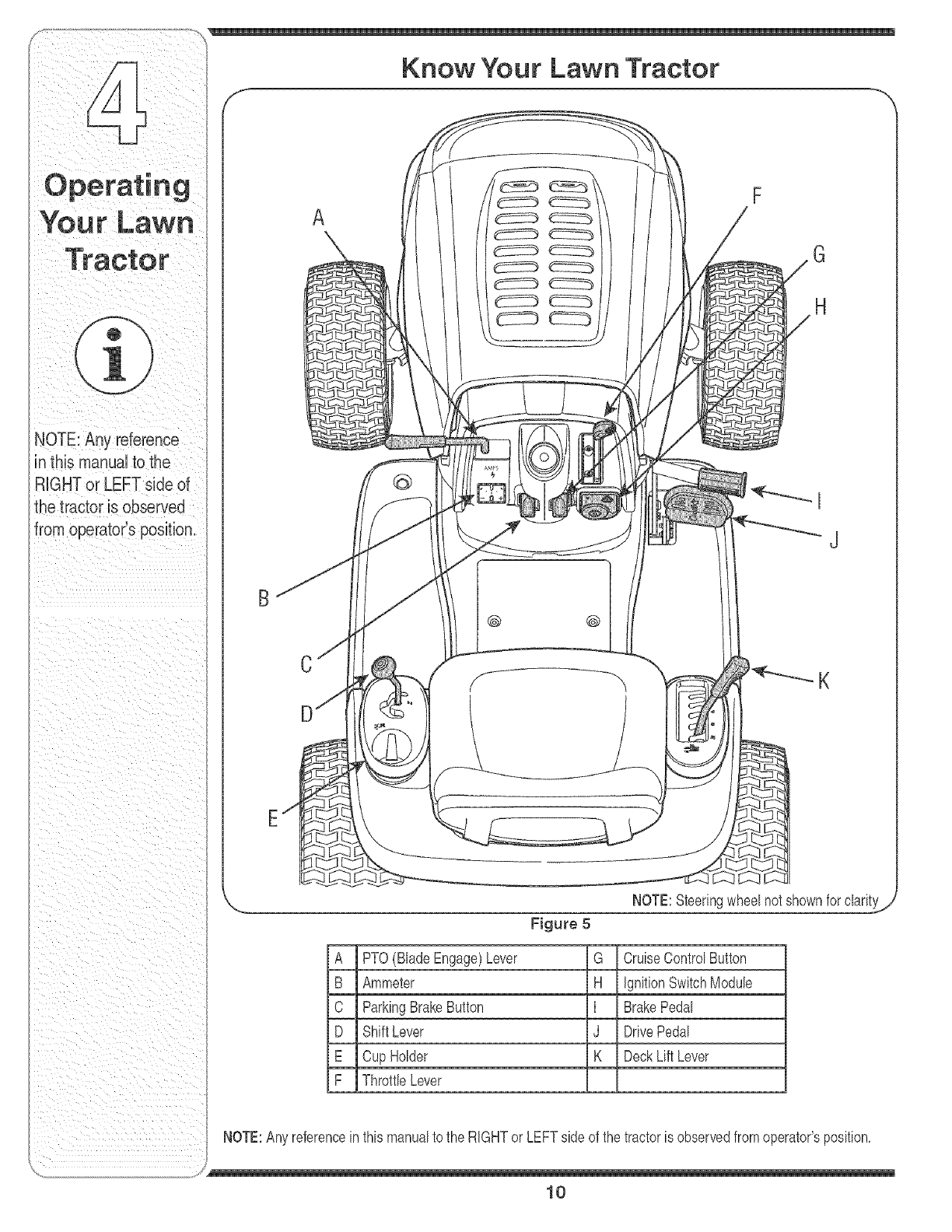
Know Your Lawn Tractor
@
@ @
H
A PTO(BladeEngage)Lever G CruiseControIButton
B Ammeter H IgnitionSwitchModule
C ParkingBrakeButton I BrakePedal
D ShiftLever J DrivePedal
E Cup Holder K DeckLift Lever
F Throttb Lever
NOTE:Anyreferencein thismanualto the RIGHTor LEFTside of the tractoris observedfromoperator'sposition,
/
10

of the engineandwhenpushedall the wayforward,the
chokecontrolalso,Whensetina given position,the
throttlewill maintaina uniformenginespeed,SeeFigure
6,
IMPORTANT:Whenoperatingthetractorwiththe cutting
deckengaged,becertainthatthe throttb bver is always
inthe FAST(rabbit)position,
Choke Control
Movingthethrottle bver all theway
forwardactivatestheengine'schoke
control Activatingthe chokecontrol
closesthe chokeplateonthe carbu-
retorandaids instartingthe engine,
Referto Starting The Engine in this
section of the manualfordetailed
startinginstructions,
Drake PedaJ
Thebrakepedalis locatedonthe
rightfrontside of the tractorabove
the drivepedalalongthe running
board,The brakepedalcan be
usedfor suddenstopsor settingthe
parkingbrake,
NOTE:The brakepedalmustbe
fullydepressedto activatethe safety
interlockswitchwhenstartingthe
tractor,
ignition Switch Module
WARNING: Never Jeavea running
machine unattended. Always
disengage PTO, move shift lever
into neutraJ position, set parking
brake, stop engine and remove
key to prevent unintended
starting.
Tostartthe engine,insertthe keyintothe ignitionswitch
andturnclockwiseto theSTARTposition,Rebasethe
keyintothe NORMALMOWINGMODEpositiononce
the enginehasfired,
Tostopthe engine,turnthe ignitionkeycounterclockwise
to the OFFposition,SeeFigure7,
f
Position
Slow _>
Position
Figure 6 J
>osition
Normal
.Mowing Mode
Start
Position
Figure 7
iMPORTANT:Priorto operatingthe tractor,referto both
Safety interlock Switches andStarting The Engine
inthissectionof the manualfor detailedinstructions
regardingthe IgnitionSwitchModub and operatingthe
tractorin REVERSECAUTIONMODE,
Drive Pedal
The drivepedalis locatedbelowthe
brakepedalon the rightfrontside of
the tractoralongthe runningboard,
Depressthe drivepedalwithyour
rightfootwhenthe tractorshift bver
is ineitherFORWARDor REVERSE
to causethetractorto move,Ground
speedis also controlbdwiththe drive
pedal Thefurtherdownthe pedalis
depressed,the fasterthe tractorwill travel The pedalwill
returnto its originalpositionwhenit's not depressed,
iMPORTANT:Alwaysset the parkingbrakewhenleaving
the tractorunattended,
11
machine unattended.
A ,vaysd sengage
PTO,move Shift lever
into neutral position,
set parking brake, stop
engine and remove key
topre_ent un!ntended
Safety Interlock
REVERSE CAUTION
!

NOTE: The PTO(Blade
Engage) levermust be
in the disengaged (OFF)
sositionwhen starting
:heengine, when
traveUingin reverseand
if the operator leaves
the seat.
f
AMPS
Figure 8
Ammeter
Theammetermeasuresthe electricaloutputof the
engine'schargingsystem.Undernormaloperating
conditions,withengineat full throttle,the ammeter
shouldindicatepositivecharge.
J
PTO (B_ade Engage} Lever
o.t i-6--I
OFF, PTO
PTO /BLADE ENGAGE
The PTO(BladeEngage)leveris locatedon the leftside
of the dashboardnextto the steeringwheel Movethe
PTO(BladeEngage)leverforwardto engagethe powerto
the cuttingdeckor other(separatelyavailable)attach-
ments;movethe PTO(BladeEngage)leverrearwardto
disengagethe powerto theattachments.
NOTE:The PTO(BladeEngage)levermust be inthe
disengaged(OFF)positionwhenstartingthe engine,
whentravelingin reverseand if the operatorleavesthe
seat.
Seat Adjustment Knobs
Toadjustthe seatposition,loosenthe twoseatadjust-
mentknobsandrepositionthe seatto the desired
position.Oncea comfortablepositionis found,tightenthe
adjustmentknobsto lockthe seatin place.Referto Seat
Adjustmentinthe Adjusting Your Tractor sectionof this
manualfor moredetailedinstructions.
Deck Lift Lever
Foundon yourtractor'srightfender,thedecklift leveris
usedto changethe heightof the cuttingdeck.To use,
movethe leverto the left, thenplacein the notchbest
suitedfor yourapplication.
Parking Brake Button
Tosetthe parkingbrake,fully
depressthe brakepedalandpush
the parkingbrakebuttonin. Hold
the buttonin whiletakingyour foot
offthe brakepedal.Boththe park-
ingbuttonand the brakepedalwill
thenstay depressed.To release
the parkingbrake,depressthe
brakepedalslightly.The parking
brakebuttonwill thenreturnto its
originalposition.
NOTE:The parkingbrakemustbesetif theoperator
leavesthe seatwiththe enginerunningor the enginewill
automaticallyshutoff.
IMPORTANT:Alwayssetthe parkingbrakewhen leaving
the tractorunattended.
,J
12

Thecruisecontrolbuttonis
locatedonthe tractordash
panelto the leftof the ignition
switch,Pushthe cruisecontrol
buttonwhiletravelingforwardat a
desiredspeed,While holdingthe
buttonin, releasepressurefrom
the drivepedal Thiswill engage
the cruisecontrolandallowthe
tractorto remainat thatspeed
withoutapplyingpressureto the
drivepedal Depressthe brake
pedalor the drivepedalto deactivatecruisecontrol
Referto Setting the Cruise Control laterinthis section
the manualfor detailedinstructionsregardingthe cruise
controlfeature,
NOTE:Cruisecontrolcan NOTbe engagedat the
tractor'sfastestgroundspeed,if the operatorshould
attemptto doso,the tractorwill automaticallydecelerate
to the fastestoptimalmowinggroundspeed,
Shift Lever
Theshift leveris locatedon the
leftside of the fenderand has
threepositions,FORWARD,
NEUTRALand REVERSE,The
brakepedalmustbe depressed
andthe tractormustnot bein
motionwhenthe movingshift
lever,
IMPORTANT:Neverforcethe
shift lever,Doingso mayresultin
seriousdamageto the tractor's
transmission,
Safety JnterJock Switches
Thistractoris equippedwitha safetyinterlocksystem
for the protectionof the operator,If the interlocksystem
shouldevermalfunction,donot operatethe tractor,
ContactanauthorizedWhiteOutdoorservicedealer,
, Thesafetyinterlocksystempreventstheengine
fromcrankingor startingunlessthe parkingbrakeis
engaged,and the PTO(BladeEngage)leveris inthe
disengaged(OFF)position,
• Theenginewill automaticallyshutoff if theoperator
leavestheseatbeforeengagingthe parkingbrake,
leverinthe engaged(ON)position,regardlessof
whetherthe parkingbrakeis engaged,
Withthe ignitionkeyinthe NORMALMOWING
position,the enginewillautomaticallyshutoff if the
PTO(BladeEngage)leveris movedintothe engaged
(ON) positionwiththe shift leverin Reverse,
Reverse
WARNING: Do not operate the
tractor if the interlock system
is malfunctioning. This system
was designed for your safety and
protection.
Caution Mode
WARNING: Use extreme caution
whiJeoperating the tractor in
the REVERSE CAUTION MODE.
Always look down and behind
before arid while backing. Do not
operate the tractor when children
or others are around. Stop the
tractor immediately if someone
enters the area.
The REVERSECAUTIONMODEpositionof the key
switchmoduleallowsthe tractorto be operatedin
reversewiththe blades(PTO)engaged,
iMPORTANT:Mowinginreverseis not recommended,
To usethe REVERSECAUTIONMODE:
iMPORTANT:TheoperatorMUSTbeseatedinthe
tractorseat,
1, Starttheengineas previouslyinstructedin this
Operator'sManuak
13
WARNING
Do not operate the
tractor if the interJock
system is maJfunction-
ing. This system was
designed for your
safety and protection.
Use extreme caution
while operating the
tractor in the REVERSE
CAUTION MODE.
AJways Jookdown and
behind before and
Nhile backing. Do not
operate the tractor
when ehiJdren or oth-
ers are around. Stop
the tractor immediateJy
if someone enters the
area.

Reverse
ndicator .Push Button
Light Reverse
Stop CautionMod_
Position Position
Start
Position
X... ..,,'
Fig.re'
2. Turnthe keyfromthe NORMALMOWING(Green)
positionto the REVERSECAUTION_,IODE(Yellow)
positionof the keyswitchmodule. SeeFigure9.
3. Depressthe REVERSEPUSHBUTTON(Orange,
TriangularButton)at the top,rightcornerof the key
switchmodub.The red indicatorlight atthe top,left
cornerof the keyswitchmodulewill beON while
activated.SeeFigure9.
4. Onceactivated(indicatorlightON), thetractorcan
bedrivenin reversewith the cuttingblades(PTO)
engaged.
5. Alwayslook downand behindbeforeandwhile
backingto makesure nochildrenarearound.
6. Afterresumingforwardmotion,returnthe keyto the
NORMALMOWINGposition.
IMPORTANT:The REVERSECAUTIONMODEwill
remainactivateduntil:
a. The keyis placedin eitherthe NORMALMOW-
INGpositionorSTOPposition.
b. Theoperatorengagesthe parkingbrakebyfully
depressingthe brakepedalandholdingit down
whilegentlypushingtheparkingbrakebutton
inward,
Engaging the Parking Brake
Toengagethe parkingbrake:
1. Fullydepressthe brakepedalandhold it downwith
yourfootwhilegentlypushingtheparkingbrake
buttoninward.
2. Holdthe parkingbrakebuttoninwhile removingyour
footfromthebrakepedal
AVOID SERIOUS INJURY OR DEATH
GO UPAND DOWNSLOPES,NOT ACROSS,
AVOIDSUDDENTURN&
DO NOT OPERATETHE UNITWHEREIT COULDSLIP ORTIR
IFMACHINESTOPSGOINGUPHILL,STOPBLADE(S)AND
BACKDOWNHILLSLOWLY
DO NOT MOWWHEN CHILDRENOR OTHERSAREAROUND,
NEVER CARRYCHILDREN,EVENWITH BLADES OFE
LOOK DOWNAND BEHINDBEFOREAND WHILE BACKING.
KEEP SAFETYDEVICES(GUARDS,SHIELDS,AND SWITCHES
IN PLACEAND WORKING,
REMOVEOBJECTSTHATCOULDBE THROWNBYTHE
BLADE(Sb
KNOW LOCATIONAND FUNCTIONOF ALL CONTROLS.
BE SUREBLADE(S) AND ENGINEARESTOPPEDBEFORE
PLACINGHANDSORFEET NEAR BLADE(Sb
BEFORE LEAVINGOPERATOR'SPOSITION,DISENGAGE
BLADE(S), PLACETHESHIFT LEVER IN NEUTRAL ENGAGE
BRAKE LOCK SHUTENGINEOFF AND REMOVEKEY_
READ OPERATOR'S MANUAL
3. Onceengaged,the parkingbrakebuttonandthe brake
pedalwill lockin the "down"position.
Todisengagethe parkingbrake:
1. Slightlydepressthe brakepedal
NOTE:The parkingbrakemustbe engagedif the operator
haves the seatwiththe enginerunningor the enginewill
automatballyshutoff.
Setting the Cutting Height
1. Sebct the heightpositionof the cuttingdeckby placing
the decklift leverin anyof thesixdifferentcutting
heightnotchesonthe right sideof the fender.
2. Adiustthe deckwheelsso thattheyarebetween
_4=inchand_/2=inchabovethegroundwhenthetractor
is ona smooth,flatsurfacesuchas adriveway',
WARNING: Keep hands and feet
away from the discharge opening
of the cutting deck.
/
14

_i iii
NOTE:The deckwheelsarean anbscalp featureof the 1, Ifthe bladesareengaged,placethe PTO(Blade
deckandarenotdesignedto supportthe weightof the Engage)leverin thedisengaged(OFF)position,
cuttingdeck, 2, Turnthe ignitionkeycounterclockwiseto the STOP
Referto Leveling the Deck on page18of thismanual position,
for moredetailedinstructionsregardingvariousdeck 3, Removethe keyfromthe ignitionswitchto prevent
adiustments, unintendedstarting,
Starting the Engine
.,_ilil_l WARNING: Do not operate the
tractor if the interlocksystem is
malfunctioning. This system was
designed for your safety and
protection.
NOTE:Referto the TRACTORSET-UPon page8 of this
manualfor GasolineandOilfill-up instructions,
1, insertthe tractorkeyintothe ignitionswitch,
2, Race the PTO(BladeEngage)leverinthe disem
gaged(OFF)position,
3, Engagethe tractor'sparkingbrake,
4, Activatethe chokecontrol,
5, Turnthe ignitionkeyclockwiseto the STARTposition,
Afterthe enginestarts, releasethe key,it will returnto
the ON position,
IMPORTANT:Do NOTholdthe keyin the STARTposi-
tionfor longerthan ten secondsat a time,Doingso may
causedamageto your engine'selectricstarter,
6, Afterthe enginestarts,deactivatethe chokecontrol
andplacethe throttlecontrolinthe FASTposition,
NOTE:Do NOTleavethechokecontrolonwhileoperat-
ingthe tractor,Doingso will resultina "rich" fuelmixture
andcausethe engineto runpoorly,
Stopping the Engine
Driving The Tractor
WARNING: Avoid suddenstarts,
e×-cessive speed and sudden
stops.
WARNING: Do not leave the seat
of the tractor without first placing
the PTO(Blade Engage} lever in
the disengaged (OFF} position,
depressing the brake pedal and
engaging the parking brake. If
leaving the tractor unattended,
also turn the ignition key off and
remove the key.
1, Depressthe brakepedalto releasethe parkingbrake
and letthe pedalup,
2, Movethe throttleleverinto the FAST(rabbit)position,
IMPORTANT:Do NOTuse theshift leverto changethe
directionof travelwhenthetractoris inmotion,Always
usethe brakepedalto bringthe tractorto acomplete
stopbeforeshifting,
3, To moveforward,placethe shift leverinthe FOR-
WARDposition,thenslowlydepressthe drivepedal
untilthe desiredspeedis achieved,
4, To movein reverse,placethe shift leverinthe
REVERSEposition,checkthatthe areabehindis
clear thenslowlydepressthe drivepedal
WARNING: if you strike a foreign
object, stop the engine, discon-
nect the spark plug wire(s)
and ground against the engine.
Thoroughly inspect the machine
for any damage. Repair the
damage before restarting and
operating
15
WARNING
Do not operate the
tractor if the interlock
system is malfunction-
ing. This system was
designed for your
safety and protection.
if you strike a foreign
object, stop the
engine, disconnect
the spark plug wire(s)
and ground against
the engine. Thoroughly
inspect the machine
for any damage. Repair
the damage before
restarting and operat-
ing.
Do not leave the seat
of the tractor without
first placing the PTO
(Blade Engage) lever in
the disengaged (OFF)
position, depressing
the brake pedal and
engaging the parking
brake. If leaving the
tractor unattended,
also turn the ignition
key off and remove the
_ey.

!'!! ,i
/"q Driving On S_opes Tochangeto the reversedirectionwhenoperatingwith
/A E Referto the SLOPEGAUGEon page3 to helpdeter= cruisecontrol,depressthe brakepedalto disengagethe
///_ L mineslopeswhereyou mayoperatethe tractorsafely, cru,secontroland bnngthe tractortoe completestop,
F] Thenplacethe shift leverinthe REVERSEpositionand
WARNING: Do not mow on depressthedrivepedal,
t,NING
tractor could overturn
and cause serious
injury.
To help avoid blade
contact or a thrown
object injury, keep
bystanders, helpers,
children and pets at
least 75 feet from the
machine while it is in
operation. Stop ma-
chine if anyone enters
the area.
inclines with a slope in excess
of 15 degrees (a rise of approxi-
mately 2-1/2 feet every 10feet).
The tractor could overturn and
cause serious injury.
Mowupanddownslopes,NEVERacross,
Exerciseextremecautionwhenchangingdirection
onslopes,
• Watchfor holes,ruts,bumps,rocks,orotherhidden
obiects,Uneventerraincouldoverturnthe machine,
Tall grasscan hideobstacles,
• Avoidturnswhendrivingona slope,Ifa turn must
be made,turn downthe slope,Turningupa slope
greatlyincreasesthechanceof a rollover,
, Avoidstoppingwhendrivingupa slope,If it is
necessaryto stopwhiledrivingupa slope,start up
smoothlyandcarefullyto reducethe possibilityof
flippingthetractoroverbackward,
Setting The Cruise Control
1, Race the shiftleverin the FORWARDposition,
thenslowlydepressthedrive pedaluntilthedesired
speedis achieved,
2, Lightlydepressthe cruisecontrolbutton,
3, While continuingto holdthe cruisebuttonin, liftyour
footfromthedrive pedal(youshouldfeel thecruise
latchengage),
Onceengaged,thecruisecontrolbuttonand thedrive
pedalwill lockin the "down"position,and thetractorwill
maintainthe sameforwardspeed,
NOTE:Cruisecontrolcan not beengagedat the
tractor'sfastestgroundspeed,If the operatorshould
attemptto doso,the tractorwill automaticallydecelerate
to the fastestoptimalmowinggroundspeed,
Engaging the Blades
Engagingthe PTO(BladeEngage)transferspowerto the
cuttingdeckor other (separatelyavailable)attachments,
Toengagethe blades,proceedas follows:
1, Movethe throttlecontrolleverto the FAST(rabbit)
position,
2, Graspthe PTO(BladeEngage)leverandpivotit allthe
wayforwardintothe engaged(ON) position,
3, Keepthe throttleleverinthe FAST(rabbit)position
for the mostefficientuseof the cuttingdeckor other
(separatelyavailable)attachments,
IMPORTANT:Theenginewillautomaticallyshutoff if the
PTOis engagedwith the shiftleverin positionfor reverse
travelwiththe ignitionkeyinthe NORMALMOWING
position,Referto SafetyInterlockSwitchesearlierinthis
section,
Using the Deck Lift Lever
Toraisethe cuttingdeck, movethe decklift leverto the
left, thenplace it inthe notchbestsuitedfor yourapplica-
tion,Referto SettingThe CuttingHeightearlierin this
section,
Mowing
WARNING: To help avoid blade
contact or a thrown object injury,
keep bystanders, hetpers, children
and pets at least 75 feet from the
machine while it is in operation.
Stop machine if anyone enters the
area.
Thefollowinginformationwill behelpfulwhenusingthe
cuttingdeckwith yourtractor:
Disengagethe cruisecontrolusingoneof the following
methods:
1, Depressthe brakepedalto disengagethe cruise
controlandstopthe tractor,
2, Lightlydepressthe drivepedal
J
16

WARNING:PJanyourmowing
patternto avoiddischargeof
materialstowardroads,side°
waJks,bystandersandthelike.
Nso, avoid discharging material
against a wall or obstruction
which may cause discharged
materiaJ to ricochet back toward
the operator.
Do not mowat highgroundspeed,especiallyif a
mulchkit or grasscollectoris installed,
, For bestresultsit is recommendedthatthe firsttwo
lapsbe cutwiththe dischargethrowntowardsthe
center,Afterthefirst twolaps,reversethe directionto
throwthe dischargeto the outsidefor the balanceof
cutting,Thiswill givea betterappearancetothe lawn,
Do notcut thegrasstoo short,Shortgrassinvites
weedgrowthandyellowsquicklyin dryweather,
Mowingshouldalwaysbedonewiththeengineat full
throttle,
Underheavierconditionsit maybenecessarytogo
backover thecut areaa secondtimeto get a clean
cut,
Do NOTattemptto mowheavybrushandweedsand
extremelytall grass,Yourtractoris designedto mow
lawns,NOTclearbrush,
Keepthe bladessharpandreplacethe bladeswhen
worn,RefertoCutting Blades inthe Maintaining
YourLawnTractorsectionof this manualfor proper
bladesharpeninginstructions,
Mu{ching (If Equipped)
Somemodelscomeequippedwitha mulchkit which
incorporatesspecialblades,alreadystandardonthe
tractor,ina processof recirculatinggrassclippings
repeatedlybeneaththecutting deck,The ultra-fine
clippingsarethenforcedbackinto thelawnwherethey
actas a naturalfertilizer,Observethe followingpointsfor
the bestresultswhenmulching,
• Neverattemptto mulchif the lawnis damp,Wetgrass
tendsto stickto the undersideof the cuttingdeck
preventingpropermulchingof the clippings,
Figure 10
Do NOTattemptto mulchmorethan 1/3 the total
heightof the grassorapproximatelylq/2 inches,
Doingso will causetheclippingsto dump upbeneath
the deckandnot be mulchedeffectively,
Maintaina slowgroundspeedto allowthegrass
clippingsmoretimeto effectivelybemulched,
, Alwayspositionthe throttlecontrolleverin the FAST
(rabbit)positionandallow it to remaintherewhile
mowing,Failingto keepthe engineat full throttle
placesstrainon thetractor'sengineanddoes not
allow thebladesto properlymulchgrass,
NOTE:Itis not necessaryto removethe dischargechute
tooperatethe mowerwith the mulchkit installed,
To operatethe cuttingdeckwithoutmulching,simply
removethe mulchplugby unthreadingthe plasticwing
nutwhichfastensit to the cuttingdeck,Thiswill allowthe
clippingsto dischargeoutthe side,SeeFigure10,
Headlights
, The lampsareON wheneverthe ignitionkeyis moved
out of the STOPposition,
• The lampsturn OFFwhen the ignitionkey is movedto
the STOPposition,
17
tern to avoid discharge
of materials toward
roads, sidewalks, by-
standers and the like.
A so, avo d d scharg rig'
material against awall
or obstruction which
may cause discharged
material to ricochet
back toward the
operator.

regardingtirepressure.
Figure 11
/ / /
Figure 12
WARNING:Neverattempt to make
any adjustments while the engine is
running,except where specified in the
operator's manual.
Leveling the Deck
NOTE:Checkthe tractor'stire pressurebeforeperform-
ingany decklevelingadiustments.Referto Tires in the
Maintaining Your Tractor sectionof thismanualfor
informationregardingtire pressure.
Front To Rear
The frontof the cuttingdeckis supportedbya stabilizer
barthatcan adiustedto levelthe deckfromfrontto rear.
The frontof the deckshouldbebetween1/4-inchand
3/8-inchlowerthanthe rearof thedeck. Adiustif
necessaryas follows:
1. Withthetractor parkedona firm, levelsurface,place
the deckliftleverin the top notch(highestposition)
androtatethe bladenearestthe dischargechuteso
properadiustmentandproceed,if necessary,to the
nextstep.
3. Loosenthe twoiam nuts,if present,onthe rearsideof
the deckstabilizerbracket.
4. Locatethe locknut onthe frontsideof the stabilizer
bracket.SeeFigure11.Tightenthe lock nutto raise
the frontof thedeck; loosenthe locknut to lowerthe
frontof the deck.
5. Retightenthe twojam nutsloosenedearlierwhen
properadiustmentis achieved.
Side to Side
If thecutting deckappearsto bemowingunevenly,aside
to sideadiustmentcan beperformed.Adiustif necessary
as follows:
1. Withthetractor parkedona firm,levelsurface,place
the deckliftleverin the top notch(highestposition)
androtatebothbladesso thattheyare perpendicular
withthe tractor.
2. Measurethe distancefromthe outsideof the leftblade
tip to the groundandthe distancefrom theoutsideof
the rightbladetipto the ground.Bothmeasurements
takenshouldbeequal If they'renot,proceedto the
nextstep.
3. Loosen,butdo NOTremove,the hexcap screwon
the leftdeckhangerbracket.SeeFigure12.
4. Balancethe deckby usingawrenchto turnthe
adiustmentgear(foundimmediatelybehindthe hex
capscrewiust loosened)clockwise/uporcounteF
clockwise/down.Thedeckis properlybalancedwhen
both bladetip measurementstakenearlierareequal.
5. Retightenthe hex capscrewon the leftdeckhanger
bracketwhenproperadiustmentis achieved.
Parking Brake Adjustment
WARNING:Neverattempt to adjust the
brakes while the engine is running.
Always disengage PTO,moveshift
lever into neutral position, stop engine
and remove keyto prevent unintended
starting.
If thetractordoes notcometo a completestop whenthe
brakepedaliscompletelydepressed,orif the tractor's
rearwheelscanroll withthe parkingbrakeapplied,the
brakeis in needof adiustment.The brakedisccan be
foundonthe rightside of the transmissioninthe rearof
the tractor.Adiustif necessaryas follows:
1. Lookingat the transmissionfromthe rightsideof the
tractor,locatethecompressionspringandbrakedisc.
18

2, Loosen,but do NOTremove,the hex nutfoundon the
rightsideof the brakeassembly,SeeFigure13,
3, Usinga feelergauge,setthe gapbetweenthe brake
discandthe brakepuckat ,011",
4, Reqightenthe hexnut loosenedearlier,
Seat Adjustment
WARNING:Before operating this
machine, makesure the seat is engaged
inthe seat stop, stand behind the
machine and pull back on seat until fully
engagedintostop.
1, Flipthe seatupas shownin Figure14,
2, Loosenthetwo seatadiustmentknobslocatedunder
the seat, SeeFigure14,
3, Slidethe seatforwardorrearward,then tightenthe
knobsto lockthe seatat thedesiredposition,Put the
seatdownto the operatingposition,
Set gap ,011
Figure 13
Hex Nut
Steering Adjustment
If the tractorturnstighterinonedirectionthan theother,
or if the ball iointsarebeingreplaceddueto damageor
wear,the steeringdraglinksmayneedto beadiusted,
Adiustthedraglinksso thatequallengthsare threaded
into the balliointon the leftandright side:
1, Loosentheiam nut foundonthe draglinkat the rear
of the ballioint,SeeFigure15,
2, Removehex nuton the topof ballioint,SeeFigure15,
3, Threadthe balljointtowardtheiam nutto shortenthe
draglink,Threadthe ballioint awayfromtheiam nut
to lengthenthe draglink,
4, Replacehex nutandretightenthejam nut afterproper
adiustmentis achieved,
NOTE:Threadingthe balliointstoo far ontothe draglinks
will causethe fronttiresto "toe=in"too far,Propertoe=inis
between1/16"and5/16",
Figure 14
Fronttire toeqncan be measuredas follows:
1, Placethe steeringwheelinpositionfor straightahead
travek
2, Infrontof the axle,measurethe distancehorizontally
fromthe insideof the left rimto the insideof the right
rim,Notethe distance,
3, Behindtheaxle,measurethe distancehorizontally
fromthe insideof the left rimto the insideof the right
rim,Notethe distance,
4, The measurementtakenin frontof the axle shouldbe
between1/16"and5/16"lessthanthe measurement
takenbehindthe axle,Adiustif necessary,
Figure 15
19
NOTE:Threading the
bal joints too far onto
the drag linkswill cause
the front tires to "toe-in'
too far, Propertoe-in
is between 1/16"and
5/16".

inorder te rep!acethe
/
,r Single Shown
J
Figure 16
WARNING: Before performing
any maintenance or repairs,
disengage PTO, move shift Jever
into neutraJ position, set parking
brake, stop engine and remove
key to prevent unintended
starting.
Engine
Referto the KoNer Operator/Owner Manual for
engine maintenance instructions.
Checkengine oil level beforeeachuseas instructed
in the KohbrOperator/OwnerManualpackedwithyour
unit,Follow the instructionscarefully.
Changing Engine Oil
NOTE:Dependingonthe enginemodelfoundon your
tractor,it maybenecessaryto removethe tractor'sside
panelinorderto replacethe oilfilter (if so equipped),
1, Popopenthe protectivecap onthe endof the oil
drainvalveto exposethe drainport, SeeFigure16,
2, Removetheoil fill cap/dipstick fromthe oil fill tube,
3, Pushthe oildrainhose(packedwiththismanual)
ontothe oildrainport,Routetheoppositeendof the
hoseintoan appropriateoil colbction containerwith
a capacitygreatenoughto colbct the usedoil
4, Aftertheoil has finisheddraining,pushtheoil drain
valvebackin, rotateit clockwiseto lockthe valve
closedandre=capthe endof the oil drainvalveto
keepdebrisfromenteringthedrainport,
5, Servicethe oilfilter (if soequipped)as instructedin
the separateKohbr Operator/OwnerManualpacked
withyourunit,
Performthe abovestepsinthe oppositeorderafteroil
hasfinisheddraining,
6, Refillthe enginewith newmotoroilas instructedinthe
KohlerOperator/OwnerManualpackedwithyour unit,
IMPORTANT:Referto the KohlerOperator/Owner
Manualpackedwithyourunit for informationregardingthe
quantityand properweightof motoroil
Air Cleaner
Servicethe pre=cbaner,if so equipped,andcartridge/air
cbaner elementas instructedin the KohbrOperator/
OwnerManualpackedwithyour unit,
Spark PJug(s)
Thesparkplug(s)shouldbecleanedandthe gapreset
oncea season,Sparkplugreplacementis recommended
at the startof each mowingseason,Referto the Kohbr
Operator/OwnerManualfor correctplugtypeandgap
specifications,
Lubrication
WARNING: Before lubricating,
repairing, or inspecting,atways
disengage PTO, move shift lever
into neutral position, set parking
brake, stop engine and remove
key to prevent unintended start-
ing.
Engine
Lubricatethe enginewithmotoroil as instructedinthe
KohlerOwnerManualpackedwith yourunit,
Pivot Points & Linkage
Lubricateall the pivotpointson the drivesystem,parking
brakeandlift linkageat bast oncea seasonwithlightoil
Rear Wheels
The rearwheelsshouldberemovedfromthe axlesonce
a season,Lubricatethe axlesandthe rimswell with an
all=purposegreasebeforere=installingthem,
Front AxJes
Eachendof the tractor'sfrontpivotbaris equippedwith a
greasefitting,Lubricatewitha greasegun afterevery25
hoursof tractoroperation,
Cleaning the Engine And Deck
Anyfuel oroil spilledonthe machineshouldbewiped
off promptly,DoNOTallowdebristo accumulatearound
the coolingfinsof the engineoron anyotherpart of the
machine,
IMPORTANT:The useof a pressurewasherto cban your
tractoris NOTrecommended,It maycausedamageto
ebctrbal components,spindles,pulleys,bearingsor the
engine,
20

Deck Wash System TM
Yourtractor'sdeckmaybeequippedwitha waterport on
itssurfaceas part of itsdeckwashsystem,
If equipped,usethe DeckWashSystemTM to rinsegrass
clippingsfromthe deck'sundersideandpreventthe
buildupof corrosivechemicals,Completethe following
stepsAFTEREACHMOWING:
1, Drivethe tractorto a level,clearspoton yourlawn,
nearenoughto a watersillcock(spigot)for your
gardenhoseto reach,
IMPORTANT:Makecertainthetractor'sdischargechute
is directedAWAYfromyourhouse,garage,parkedcars,
etc,
2, Disengagethe PTO(BladeEngage),movethe shift
leverintothe neutralposition,setthe parkingbrake,
andstoptheengine,
3, Threadthe hosecoupler(packagedwithyourtractor's
Operator'sManual)ontothe endof yourgardenhose,
4, Attachthe hosecouplerto the waterport on your
deckssurface,SeeFigure17,
5, Turnthe wateron,
6, Whilesittingin theoperator'spositionon thetractor,
re=startthe engineandplacethe throttleleverinthe
FAST(rabbit)position,
7, Disengagethe parkingbrake,
8, Movethe tractor'sPTO(BladeEngage)intothe ON
position,
9, Remaininthe operator's position withthe cutting
deckengagedfor a minimumof twominutes,allowing
the undersideof thecuttingdeckto thoroughlyrinse,
10,Movethe tractor'sPTO(BladeEngage)intothe OFF
position,
11,Turnthe ignitionkeyto the STOPpositionto turn the
tractor'sengineoff andengagethe parkingbrake,
12,Turnthe wateroff anddetachthe hosecouplerfrom
the waterport onyourdeckssurface,
13,Repeatsteps4=11on theoppositeside of thecutting
deck,
Cutting Deck Removal
Toremovethe cuttingdock, proceedas follows:
1, Placethe PTO(BladeEngage)knob(or lever)in the
disengaged(OFF)positionand engagethe parking
brake,
2, Lowerthe deckby movingthedeck liftleverinto the
bottomnotchon the rightfender,
3, Removethe hairpinclip thatsecuresthePTOcableto
the rearof thecuttingdeck, SeeFigure18,Remove
the PTOcableandaccompanyingspringfrom the
cuttingdeck,
4, Removethe deckbelt fromaroundthetractor's
enginepulley,
i \
i \\
\
/' ii,_i_ ii_
,jJ
Figure 17
Figure 18
/// "
// /
Figure 19
5, Lookingat the cuttingdeckfromthe leftside of the
tractor,locatethe decksupportpinon the rearleft
side of the deck,SeeFigure19,
21
iMPORTANT
Make certain the
tractor's discharge chute
is directedAWAYfrom
your house,garage,
parkedcars. etc.

WARNING
Never exceed the
maximum inflation
_ressureshown on the
sidewall of the tire.
Batteries giveoff an
.=xplosivegas whib
:barging. Charge bat-
tery in awellventiJated
_rea and keep away
from an open flame
_r pilot light as on a
_vaterheater, space
heater, furnace, clothes
dryer or other gas
_ppliances.
Be sure to shut the
engine off, remove
ignition key, discon-
nect the spark plug
wire(s) and ground
against the engine to
prevent unintended
starting before remov=
ing the cutting blade(s)
for sharpening or
replacement. Protect
your hands by using
heavy gloves or a rag
tograsp the cutting
blade.
fromthe decklift arm,
7, Rotatethe pinslightlytowardthe rearof the tractor
andreleasethe pin intothe hob provided,
8, Repeattheabovestepson thetractor'srightside,
9, Movethe decklift bver intothe top notchonthe right
fenderto raisedecklift armsup andoutof the way,
lO,Genflyslide thecuttingdecktowardthe frontof the
tractorallowingthe hooksonthe deckto release
themselvesfromthedeckstabilizerrod,
11,Gentlyslidethe cuttingdeck(fromthe rightside)out
fromunderneaththe tractor,
Tires
WARNING: Never exceed the
maximum inflation pressure
shown on the sidewall of tire.
The recommendedoperatingtire pressureis:
Approximately10psifor the reartires
,, Approximately14psi for the fronttires
IMPORTANT:Referto the tire sidewallforexacttire
manufacturer'srecommendedormaximumpsi,Do not
overinfiate,Uneventire pressurecouldcausethe cutting
deckto mowunevenly,
Battery
The batteryis sealedandis maintenance-free,Acid
bvels cannotbe checked,
,, Alwayskeepthe batterycabbs andterminaBeban
andfreeof corrosivebuild-up,
,, Aftercleaningthe batteryandterminaB,apply a light
coatof petroleumicily or greaseto bothterminaB,
Alwayskeepthe rubberbootpositionedoverthe
positiveterminalto preventshorting,
IMPORTANT:If removingthe batteryforany reason,
disconnectthe NEGATIVE(Black)wire fromit's terminal
first,followedbythe POSITIVE(Red)wire.When
re-installingthe battery,alwaysconnectthe POSITIVE
(Red)wire itsterminalfirst,followedbythe NEGATIVE
(Black)wire.Becertainthat thewiresareconnectedto
thecorrectterminals;reversingthemcould changethe
polarityandresultindamageto your engine'salternat-
ingsystem.
Charging
If thetractor hasnot beenput into usefor anextended
periodof time,chargethe batterywith anautomotive-
type 12-voltchargerfor a minimumof one hour at six
amps.
WARNING: Batteries give off an
explosive gas while charging.
Charge battery in a well ventilated
area and keep away from an open
flame or pilot light as on a water
heater, space heater, furnace,
clothes dryer or other gas appli-
ances.
Jump Starting
WARNING: When removing or
installing the battery, follow
these instructions to prevent the
screwdriver from shorting against
the frame.
IMPORTANT:Neveriumpyourtractor'sdeadbatterywith
the batteryof a runningvehicle,
1. Connectendof oneiumpercableto the positive
terminalof thegoodbattery,thenthe otherendto the
positiveterminalof the deadbattery.
2. Connectthe otheriumpercableto the negative
terminalof thegoodbattery,thento the frame of the
unit with the dead battery.
WARNING: Failure to use this
procedure could cause sparking,
and the gas in either battery could
explode.
CJeaning
Cban the batteryby removingit fromthe tractorand
washingwitha bakingsodaandwatersolution,if neces-
sary,scrapethe batteryterminaBwitha wire brushto
removedeposits,CoatterminaBandexposedwiringwith
greaseor petroleumicily to preventcorrosion,
Battery Failures
Somecommoncausesfor batteryfailureare:
. incorrectinitialactivation • undercharging
. overcharging • corrodedconnections
. freezing
Thesefailures are NOTcovered byyour tractor's
warranty.
22

Cutting Blades
WARNING:Besuretoshutthe
engineoff, removeignition
key, disconnect the spark plug
wke(s) and ground against the
engine to prevent unintended
starting before removing the cut-
ting Made(s} for sharpening or
replacement. Protect your hands
by using heavy gloves or a rag to
grasp the cutting Made.
WARNING: Periodically inspect
the Made spindles for cracks or
damage, especially if you strike a
foreign object. Replace immedi-
ately if damaged.
Thebladesmayberemovedas follows,
1, Removethe deckfrombeneaththe tractor,(referto
CuttingDeckRemovalon page21)thengentlyflip
the deckoverto exposeitsunderside,
2, Placea blockof wood betweenthe centerdeckhous-
ingbaffleandthe cuttingbladeto act asa stabilizer,
SeeFigure20,
3, Usea 15/18"wrenchto removethe hexflangenut
thatsecuresthe bladeto thespindleassembly,See
Figure20,
4, Toproperlysharpenthe cutting blades,removeequal
amountsof metalfrombothends of the bladesalong
the cuttingedges,parallelto the trailingedge,at a
25° to 30° angle,
IMPORTANT:If the cuttingedgeof the bladehasalready
beensharpenedto within15/8" fromthe edge,or if any
metalseparationis present,replacethe bladeswith new
ones,SeeFigure21,
It is importantthateachcuttingbladeedgebeground
equallyto maintainproperbladebalance,
Whenreplacingthe blade,be sureto installthe blade
withthe sideof the blademarked"Bottom" (orwith
a part numberstampedin it) facingthe groundwhen
the moweris inthe operatingposition,
IMPORTANT:Usea torquewrenchto tightenthe blade
spindlehexflangenutto between70foot-poundsand 90
foot-pounds,
Figure 20
Figure 21
FUSES
• A fuseis installedin yourtractor'swiringharnessto
protectthe tractor'selectricalsystemfromdamage
causedby excessiveamperage,
, If the electricalsystemdoes notfunction,or your
tractor'senginewill notcrank,first checkto becertain
thatthe fusehas notblown,
, It can eitherbefoundunderthe hoodmountedbehind
the top of the dashpanelon the supportbar,or under
the seatmountedto the insideof the tractorframe
nextto the batterytray,
Always use a fuse with the same
amperage capacity for replace-
ment.
23
Periodically inspect
the Made spindles for
cracks or damage,
especially if you strike
aforeign object.
Replace immediately if
damaged.
Always use a fuse with
:he same amperage
capacity for replace-
ment.
WARNING
Be sure to shut the
engine off, remove ig=
nition key, disconnect
the spark plugwire(s)
and ground against
the engine to prevent
unintended starting
before removing the
beJt(s).
WARNING: Be sure to shut
the engine off, remove ignition
key, disconnect the spark plug
wire(s) and ground against the
engine to prevent unintended
starting before removing the
belt(s).
Allbeltson yourtractorare subiectto wearandshould
bereplacedif anysignsof weararepresent,
IMPORTANT:The V-beltsfoundon yourtractorare
speciallydesignedto engageanddisengagesafely,A
substitute(nomOEM)V-beltcan bedangerousby not
disengagingcompletely,Fora properworkingmachine,
usefactoryapprovedbelts,
Tochangeorreplacethe deckbelt onyourtractor,
proceedas follows:
1, Removethe beltkeeperrod(s)fromaroundthe
enginepulley,
2, Removethecuttingdeckas instructedearlierinthis
section,
3, Removethe beltguardsby removingthe self-tapping
screwsthatfastenthemto the deck,
4, Carefullyloosen,butdo not remove,the deckidler
pulleys,
5, Removethe deckbelt fromaroundall pulleys,including
the deckidlerpulleys,
6, Routethe newbelt as shownin Figure23 andretighten
the deckidlerpulleys,
7, Reinstallthe beltguardsremovedearlierand remount
the deckto thetractor,
8, Routethe beltaroundthe enginepulleyand reinstall
the belt keeperrod(s),
Changing the Transmission Drive
Be_t
NOTE:Severalcomponentsmust beremovedandspecial
tools(i,e,aidimpactwrench)in orderto changethe
tractor'sdrive belt,Seean authorizedMTDServiceDealer
to haveyourdrivebelt replacedor phoneCustomerSup-
port as instructedon page2 for informationonorderinga
ServiceManual
Avoid the possibility of
a pinching injury. Do
not place your fingers
on the idler spring or
between the belt and a
pulley while removing
the belt.
/
24
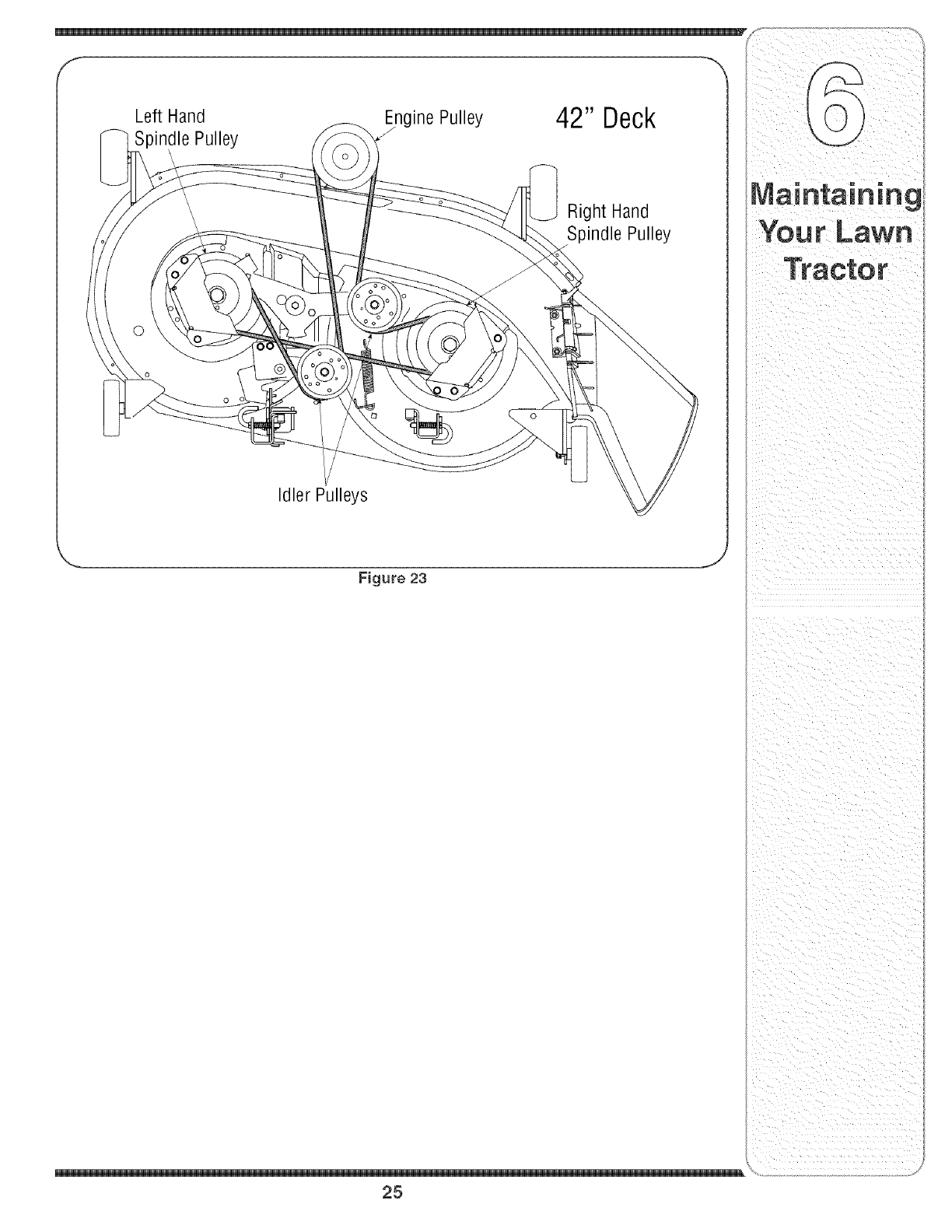
LeftHand
SpindlePulley
IdlerPulleys
inePulley 42" Deck
Right Hand
Spindle Pulley
Figure 23 J
25

; of thismanualbeforestoringfor anextendedperiod, Manualfor properenginecare priorto storingyourtractor,
WARNING
Drain fuel only into an
approved container
outdoors, away from
an open flame. Al-
low engine to coon.
Extinguish cigarettes,
cigars, pipes, and
other sources of igni=
tion prior to draining
fuel.
WARNING: Drain fueJonly into
an approved container outdoors,
away from an open flame. Allow
engine to coot. Extinguish
cigarettes, cigars, pipes, and
other sources of ignition prior to
draining fuel.
WARNING: Never store the
machine or fuel container indoors
where there is an open flame,
spark or pilot tight such as on
water heater, furnace, clothes
dryer or other gas appliance.
Attachments & Accessories
The followingattachmentsandaccessoriesare compatiblefor Model60TGSuperBroncoLawnTractors,Seethe
retailerfromwhichyoupurchasedyourtractor,anauthorizedTroyBilt ServiceDealeror phone1-866-840-6483for
informationregardingprice andavailability,
NOTE:Model60TGLawnTractorsare NOTdesignedfor usewithany typeof ground-engagingattachments(e,g,
filleror plow),Useofthis typeof equipmentWILLvoid thetractor'swarranty,
MODEL " DESCRiPTiON
0EM-190-032
OEM-190:116
OEM-190-180
OEM-190-218
OEM-190-607"
OEM-190-658
OEM-190-672
OEM-190-833
42-inchTwo-stageSnowThrower
42-inchDeckMulchKit
TwinBaggerGrassCollector(for42-inchDecks)
RearWheelWeightKit
DeluxeTractorSunshade
GrilleGuard(mountsonfrontof tractor)
46-inch FrontDozerBlade
Notcompatiblewithtractorsequippedwitha GrassCollector
Never store the ma-
chine or fuel container
indoors where there is
an open flame, spark
or pilot light such
as on water heater,
furnace, clothes dryer
or other gas appliance.
26

NOTE: I_ BOTAMODES,_HE_ _pE_ATORLEAVES_EAT,EfiG]N_WILL
out importantsafety
instructionswhich, if
notfollowed,couUd
endangerthe personal
safetyand/or property
dyourselfandothers.
ReadandfollowaH
instructionsinthis
manualbeforeat-
temptingto operate
this machine,FaiBre
to complywith these
instructionsmayresult
in personalinjury,When
yousee thissymbol,
HEED iTS WARNING!
Your Responsibility
Restrictthe use
of this power machine
to personswho reao
understand
andfollow the warnings
\
27

For repairs beyond
the minor adjust-
ments listed here,
contact an authorized
service dealer.
Problem
Engine runs erratic
Cause
1, UnitrunningwithCHOKEapplied,
2, Sparkplugwire(s)loose,
3, Blockedfuel lineor stab fuel
4, Ventingas cap plugged,
5, Waterordirt infuel system,
6, Dirty aircbaner,
Remedy
1. PlacePTOknob (orlever)in
1, PushCHOKEcontrol(if so
equipped)in, or movethe throttle
controlout of the CHOKEposition,
2, Connectand tightenspark
plugwire(s),
3, Cban fuel line;fill tank withclean,
fresh(lessthan30 daysold)
gasoline,Replacefuel filter,if so
equipped,
4, Char ventor replaceif damaged,
5, Drainfuel tank, Refillwith
freshfuel
6, Replaceaircleanercartridge/eb=
mentor cleanpre=cleaner,if so
equipped,
28

Problem Cause Remedy
. 2, Air flowrestrbted,' 2, CLeangrassclippingsanddebris
, , aroundthe engine:scoe!!ng
•• finsandbbwer housing.
Enginehesitates at 1, Sparkplug(s)gaptooclose, 1, Removesparkplug(s)and reset
high RPM thegap,
' ..... equipped, ........ .....
Excessive
Vibration
Uneven cut
1, Cuttingbladelooseor unbalanced,
2, Damagedor bentcutting blade,
1, Decknot balancedproperly,
2, Dullblade,
3, Uneventire pressure,
1, Tightenbladeandspindle,Balanc(
blade,
2, Replaceblade,
1, Performside-to-sidedeckadiust-
ment,
2, Sharpenor replaceblade,
3, Checktire pressureinall fourtires,
For repairs beyond
the minor adjust-
ments listed here,
contact an authorized
service dealer,
29

Model 60TG
Models w/Quick
Adjust Seat
Modelsw/Manually
AdjustingSeat
..... i
t_ ¸¸¸•'(iii_ii_ii_'i!¸ •
3O

Ref. Part No. Description
No.
1 710-1268t Screw,#10-16x.375
2 712-04063 Nut, FlangeLock,5/16-18,GrF
3 712-3027t Nut, FlangeLock, 1/4-20
4 720-0309At SeatAdiusterGrip
5 726-0201t Nut, Speed,.3125ID
6 731-04074f Spacer
7 732-0499t CompressionSpring.41x 1.5
8 732-1184 Spring,Extension,.84Dia.x 4.6
9 736-0275t Wash,Flat,.344x.688x.065
10 736-3019t Wash,Flat,.531x1.062x.134
11 738-0137At Screw,Shld, .340x.285,1/4-20
12 738-0296 Screw,Shoulder,.437x.268
13 738-0966t Screw,Should,.50x.925,3/8-16
14 783_0209D SeatBracket,Lift
15 783_0611t SeatStop
16 783-0738Ct SeatPivotBracket
17 783-0739At SeatAdiustmentLever
18 783-0753t SeatAdiustmentSelector
19 757-04001 LowBackSeat
20 726_3046 RatchetClip
21 735-0657 LR FootPad, Rubber
22 735-0656 RHFootPad,Rubber
23 710_0451 Bolt,Carriage,5/16_18.75,Grl
24 710-0599 Screw,1/4-20,0.500
25 710-0604A Screw,5/16-18,0.625
26 710-0895 Screw,1/4-15,0.750
27 731_1990 Cover,Lift Lever
28 731-2104C Cover,w/ CupHolder
29 736-3078 Washer,Flat,.344x 1.0x.063
30 783_04333A Fender
Ref. Part No. Description
No.
31 783-0677B Adiust.Brkt.,Lift
32 783-1489B MountingBracket,Seat
33 710_0227 Screw,#8_18x.50
34 726_0279 Plate,Insulator
35 725_1303 SpringSwitch,Outer
36 725-1439 SpringSwitch,inner
37 726_0278 Plate,InsulatorBoss
38 683_04079 ShaftAssembly,Lift
39 712-04065 Nut,FlangeLock,3/8-16,GrF
40 714-0104 Pin,Cotter,.072Dia.x 1.13
41 714-0111 Pin,Cotter,3/32, 1.0
42 716-0106A Ring,EType,.625Dia.
43 720-0311 Grip, Handle,1/2
44 732_0874 Spring,Torsion
45 738-0138A Screw,5/16-18x.620Gr2
46 738-04130 Scr.,Shldr,.625x.165
47 741-0225 Bearing,RexFlange
48 746_0968 Cable,Lift, 16.16
49 747-04155 Handle,Lift
50 756_1154 Pulley,Roller
51 783_04494 Arm,Lift_RH
783-04711 Arm,Lift- LH
52 736-0607 LockWasher,5/16
53 710-0726 Screw,5/16-12
54 738-04012At ShoulderScrew
55 720-04061t Knob,3/8-16
56 736-0300t FlatWasher,.406x .875x .059
57 783-04081At SeatPivotBracket,ManualAdi.
58 710-0870t HexHeadWasherScrew,3/8_16
tif Equipped
NOTE:Tractorfeaturesvaryby model NOTall partslistedaboveandpicturedonthe previouspagearestandard
equipment.
parts,calltheCustomer
Service Line at
\
31

Model 60TG
32

Ref. Part No. Description
No.
1 710-04095 HexScrew,3/8-16,1,00,Gr5
2 710-0514 HexScrew,3/8q6, 1,00,Gr5
3 710-0843 HexScrew,5/16q8, 1,00,Gr5
4 711q408 Link,Drag,RH
5 711q409A Link,Drag,LH
8 712-0214 Nut, HexLock,3/8-24
7 712-04065 Nut, FlangeLock,3/8q6, Grf
8 712-0459 Nut, FlangeLock,7/16-20
9 712-3004A Nut, FlangeLock,5/16q8, Gr5
10 712-0240 Nut,Jam,7/16-20,Gr2
11 717q550E Gear,Steering,11/90Ratio
12 717q554 Gear,Pinion,Steering
13 723-0448A BaliJoint,7/16-20,Lock
14 736-3004 Washer,Flat,,406x,875x,105
15 738-3084 Washer,Flat,,51x 1,12x,08
16 710q260A Screw,5/16q8, 0,750
17 738-04154 Spacer,Shoulder,,38x 1,00x,31
18 738qOO1A Shaft,Steering,,6250D x24,25
19 741-0475 PlasticBushing,3801D
20 738-0143 Screw,Shoulder,,498 x,340
21 783-0726E PivotBracket,SupportRH
22 783_0727D PivotBracket,SupportLH
23 783-0728 PivotBracket,Bar
24 631-04028 SteeringWheel
25 731-04681 SteeringWheeICap
26 738-04128 ShoulderScrew,,5x2,380, 3/8q6
27 734_2290A DeluxeRubCap
28 738-0316 FlatWasher,,78 x 1,589x ,06
29 714-04039 CotterPin,5/32x 1,25
30 719-04105 CastIron PivotBar
31 731-04693 PushCap
32 638_04006 LH AxleAssembly,,750
33 638_04005 RHAxle Assembly,,750
34 728-04035 PushNut
35 783_04568 FrontDeck HangerBracket
36 712-0431 FlangeLockNut, 3/8q6
37 741-0656A HexFlangeBearing
38 634_04086 Wheel AssemblyComplete,15x 6
7344731 Tire Only 15x 6 x 6
634-04081 RimOnlyw/Valve Stem
parts, call the Customer
service Line at
or visit
wwWitioyb t,¢om:
\
33

Mode_ 60TG
\\\
/
34

Fief. Part No.
No.
1 710-0728
2 710-0599
3 783-04829
4 746-1084
5 731-1999
6 731-05357
7 738-04091
8 783-04827
9 783-04828
10 783-04840
783-04841
11 783-04606A
12 712-0185
13 751-10283
14 751-0603
15 710-1017
16 710-0895
17 710-3217
18 712-0142
Description
Screw,5/16-12x.750
Self-tappingScrew,1/4-20x.5
SidePanel- LH
ThrottleControl/Cable
ChokePlug
HeadlightLens
ShoulderScrew.43x.29
Hood,T Style
SidePanel- RH
PivotBracket- RH
PivotBracket- LH
GrillPivotBracket
SpeedNut
FuelTank,ThreeGallon
FuelCap
Screw,1/4-14x.625
Self-tappingScrew,1/4-15x.75
TrussPhillipsScrew,#8-32x.375
HexNut,#8-32
Ref. Part No.
No.
19 731-1857
20 731-05001A
21 731-04729
22 731-04728
23 747=04161
24 747=1196
25 629-04083t
26 725-04156
27 783-04908
28 710-0642
29 783-04909
30 725-0963
31 736-0270
32 710-1611B
33 725-1649
34 725-04227A
35 725-1745
725-1744
-- 725-04334t
Description
ThrottleControlKnob
DashPanel
CruiseControlButton
ParkingBrakeButton
TankSupportRod
Brake/CruisePivotRod
HeadlightWire Harness
SystemsInd. Monitorw/Ammeter
RHDashSupportPlate
Self-tappingScrew,1/4-20x.75
LHDashSupportPlate
Lamp
BellWasher.265x.75x.062
Screw,5/16-18x.75
HeadlightSocket
ignitionSwitch
ignitionKeyw/plastic cover
ignitionKeyw/oplasticcover
Wire Harness
t NotShown
_FACTORY PARTS
\
35

Model 60TG
Left Hand Transmission
Bolt Mounting
36

Ref. Part No. Description
No.
1 17840 MountingBracket,Transaxle
2 725-04039 Switch,Interlock
3 17962 Plate,Switch
4 647-04020 LeverAssembly,Shift
5 710-0607 Screw,5/16-18,0.500
6 710-0726 Screw,5/16-12,0.750
7 710-0809 Screw,1/4-20,1.250
8 710-1007 Screw,Seres,3/8-16,1.500
9 710-1266 Screw,5/16-18,3.50,Gr5
10 710-3144 Screw,3/8-16,2.00,Gr5
11 711-0736 AdiustmentFerrule1/4-20x 1.
12 712-0241 Nut,Hex,3/8-24,Gr5
13 712-04063 Nut,FlangeLock,5/16-18,GrF
14 712-0431 Nut,FlangeLock,3/8-16,GrF
15 712-0700 Nut,Flange,9/16-18,Gr2
16 714-0104 Pin,Cotler.O72Dia.x 1.13
17 714-0111 Pin,Cotter,3/32, 1.0
18 714-0209 CotterPin,Internal,.125Dia.
19 714-0470 Pin,Cotter,1/8x 1.25
20 718-0758A PulleyHub,5/8 Spline
21 720-04028 Knob,Shift
22 723-3018 BallJoint
23 731-04602 Sleeve.758x.821x3.3125
24 731-04604 Sleeve.758x.821x 2.4375
25 732-0384 Spring,Extension,.62Diax 6.12
26 732-0525 SpringClip,Shifter
27 732-0716C Spring,Extension.59ODx 4.00
28 732-0963 Spring,Extension.50Diax 6.37
29 736-0169 Washer,Lock,3/8
30 710-0224 Screw,#10-16.50
31 738-0372B Spacer,Shoulder,1.00x.38x.38
32 747-04146A Rod,Shift
33 747-04164 Rod,Brake
34 747-1127 IdlerRod,Adiustable,3/8
35 748-0334 Spacer.68
36 750-0566A Spacer.260x.372x 1.030
37 754-0467 Belt,V-Type
38 754-0468 Belt,V-Type
39 756-04002 Pulley,V-Type,7.25Dia.
40 756-04224 IdlerPulley,Flat2.75OD
41 783-04283 Bracket,Shift
Ref. Part No. Description
No.
42 783-04360 Bracket,Shift,F-N-R
43 783-04442 Idler Bracket,CenterDouble
44 647-0031B ControlAssembly,Brake
45 647-0032A ControlAssembly,Speed
46 683-0266 PedalAssembly
47 710-0650 Screw,5/16-18,0.875
48 710-1260A Screw,5/16-18,0.750
49 710-1611B Screw,5/16-18,0.750
50 711-04159B Pin,3/8-16x2.68
51 731-2290A Hub Cap
52 732-0335 Spring,Compression..405x1.17
53 732-0955 Spring,Extension.50OD x 1.41
54 732-0963 Spring,Extension.50OD x 6.37
55 735-0662 Pad
56 735-3049 Pad,Brake
57 736-0187 Washer,Flat.64 x 1.24x.06, Ht
58 736-0262 Washer,Flat.385x.870x.092
59 736-0300 Washer,Flat.406 x.875x.059
60 736-3008 Washer,Flat.344x.750x.120
61 738-0155 Screw,Shoulder.437Diax.162
62 738-0380 Screw,Shoulder,.50x.27Lg,
63 741-0225 Bearing,HexFlange
84 741-3065B Split Bearing,Hex Flange
65 747-04093 Rod,BrakeLock
66 747-04096 Rod,CruiseControl
67 748-04039BI Latch,CruiseControl
68 783-0732A Bracket,Lockout
69 783-0773A Ped,Brake
70 783-04612 Bracket,SteeringSupport
71 618-04034 Transmission,SingleSpeed
72 683-04055A BracketAssembly,Torque
73 683-04130 Bracket,Idler
74 710-0227 Screw,#8-18x.50
75 710-0514 Screw,3/8-16,1.00
76 710-0604A Screw,5/16-18.625
77 710-1315 Screw,3/8-16,1.250
78 712-0130 Nut, Lock,3/8-16,Nylon
79 725-1644 SwitchSpring,Short
80 726-0320 Plate,Insulator
81 750-04294 Spacer,Shoulder
82 756-04209 Pulley,V-Type,3.06
Continued on next page
_FACTORY PARTS
To order replacement
parts, call the Customer
Service Lineat
1-800-648-6776,
orvisit
www.troybilt.com.
\
37

Model 60TG
_FACTORY PARTS
To order replacement
parts, call the Customer
Service Lineat
1=800=648=6776,
or visit
www.troy bilt.com.
Ref. I Part No. Description
No. I
83 656=04015 PulleyAss'y,VariableSpeed
84 683=04129 Bracket,Pulley
85 710=0627 Screw,5/16=24,.750
86 710=1652 Screw,1/4=20,.625
87 718=04012 Cup,Bearing
88 736=0362 Washer,Flat
89 741=0600 BallBearing
90 783=04722 SwitchBracket,ParkingBrake
91 736=0242 Washer,Bell.340x.872x.060
92 712=04065 Nut,FlangeLock,3/8=16,GrF
93 710=0599 Screw,1/4=20x.500
94 736=0430 FlatWasher.350x 1.59x.062
95 634=0104 WheelAssyComp,20x 8 x 8
734=1730 Tire Only20 x 8 x 8
734=0603A RimOnly w/Valve Stem
96 736=3010 FlatWasher,.407x .812x .135
97 714=0507 Pin,Cotter,3/32x.750
98 736=0119 LockWasher,5/16
99 725=3167 Switch
100 712=3004A Nut,FlangeLock,5/16=18,Gr 5
38

_ _"_!_*'_"_'_*'_S_°,°_ _
ustrat
I
Exhaust gasket,
f_)_ _=_ mountingnuts,and
starter nut supplied
by Kohler
Ref. Part No.
No.
1 710-0227
2 710-0599
3 783-04573
4 783-04574
5 751-3142
6 710-0654A
7 736-0277
8 751-3141
9 726-0205
10 725-0157
Description
ABScrew#8-18x 0,5
TT Screw1/4-20x 0,5
LH MufflerBracket
RHMufflerBracket
Oil DrainCap
TT Screw3/8-16x 1,00
FlatWasher,1,031x 1,620x ,095
Oil DrainExtensionHose
HoseClamp
CaNeTie
@
Ref.
No.
11 726-0272
12 751-3140
13 751-10349
14 751-0564B
15 751-10162
16 751-10017
17 710-0642
18 728-04000
19 751-10353
20 683-04256
Part No. Description
Clamp
Oil DrainValve
FuelLineHose
MufflerDeflector
Muffler
ExhaustPipe
Screw,1/4-20,x ,750
PopRivet
LongMufflerDeflector
MufflerShield
_FACTORY PARTS
To order replacement
parts, call _heCustomer
Service Line at
1o800-648-6776,
or visit
www.troybilt.com.
\
39
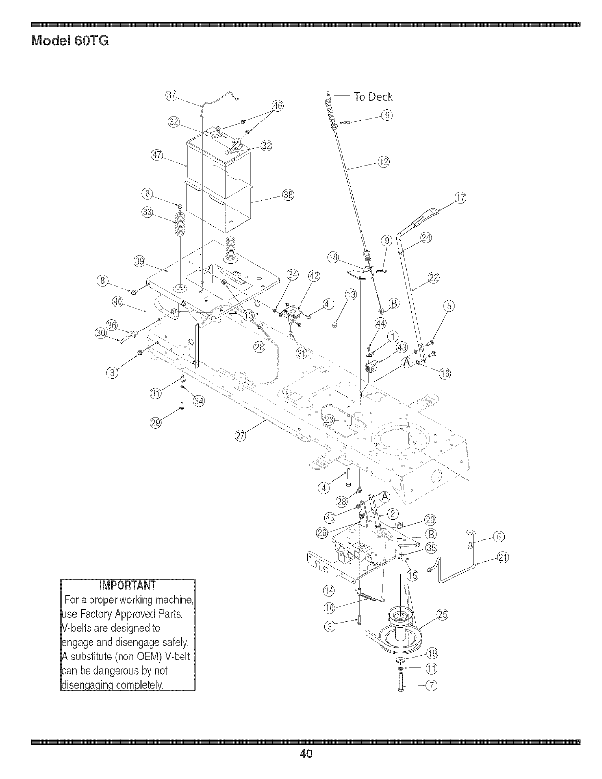
Mode_ 60TG
IMPORTANT
For a properworking machine,
Jse Factory Approved Parts.
7-beltsare designedto
_ngageand disengage safely.
substitute(non OEM) Wbeit
sanbe dangerous by not
Jisen a in corn_letel.
4O

Rof.po, ,o. Do,c,p ioo po, ,o. Do,c,p ioo
NO,
1 17962 Plate,Switch
2 647=04036 LeverAssembly,Engagement
3 710=0778 Screw,1/4=20x 1.500
4 710=0859 Screw,3/8=16,2.50
5 710=0276 Screw,Carriage,5/16=18,1.00
6 710=1260A Screw,5/16=18x.750
7 710=3157A Screw,7/16=20,3.25,Gr5
8 710=0726 Screw,5/16=12,0.750
9 714=0145 ClickPin
10 732=04248 ExtensionSpring.380D x 3.9LG
11 736=0171 LockWasher,7/16
12 746=04092 DeckEngagementCable
13 712=04065 Nut,FlangeLock,3/8=16,GrF
14 750=0566A Spacer.260x.372x 1.030LG
15 714=0470 Pin,Cotter,1/8 x 1.25
16 726=0201 Nut,Speed.3125ID
17 731=2111A Knob,PTO
18 783=04590A CableBracket
19 736=0322 Washer,Flat.450 xl.250 x.164
20 741=0708 Bearing,Flange,.500ID
21 747=04307 KeeperRod,Belt
22 747=04470 EngagementHandle,Deck
23 748=0415B Spacer.385ID x.635OD x 1.54
24 736=0108 FlatWasher,.510x .750x .033
Ref.
No.
25 756=04196 Pulley,Engine,3.39x 6.12Dia.
26 783=0744A Stop Bracket,Engagement
27 683=04173 FrameAssembly,Lower
28 710=0607 Screw,5/16=18,0.500
29 710=0642 Screw,1/4=20,0.750
30 710=3005 Screw,3/8=16,1.25,Gr5
31 712=04064 Nut, FlangeLock, 1/4=20,GrF
32 710=0703 Screw,Carriage,1/4=20,.75
33 732=04035 Spring,Compr., 1.28OD x 3.125
34 736=0222 Washer,Lock,1/4,External
35 736=0275 FlatWasher,.344x .688x .065
36 738=04058 Spacer,Shoulder.38x 1.0x.70
37 747=04121A Hold Rod,Battery
38 783=0349 BatteryTray
39 783=04329A SeatBracket,Frame
40 783=04809 Frame,Upper
41 710=0599 Screw,1/4=20,0.50
42 725=1428A Solenoid,12V,100Amp
43 725=04039 Switch,Interlock
44 710=0224 Screw,#10=16,.50
45 712=3004A Nut, Flange,LockNut, 5/16=18
46 712=0271 Nut, Seres,1/4=20
47 725=1737A Battery,190CCA
i ii ii i i i
ii¸toOrdorrepocement
parts;Callthecustome,
Service Line at
\
41

Model 60TG
42

Ref. Part No. Description
No.
1 732-0614 Ring,Wire
2 716-0231 Ring,E Type.750
3 736-0336* FlatWasher,5/8x 1.0x.030
736-0337* FlatWasher,5/8 x 1.0x.040
736-0349* FlatWasher,5/8 x 1.0x.020
4 736-0335 Washer,Thrust.635x 1.26x.06
5 710-1325 Self-tappingScrew,1/4-20x 1.625
6 719-04017 UpperRousing
7 711q109 input Shaft
8 741-0335 NeedleBearing.625x.813x.495
9 717-1464 144oothBevelPinion
10 716-0108 RetainingRing.437
11 741-0340 SleeveBearing.75x.1.0x 1.0
12 721-0338 Seal.75x 1.0x.125
13 618-04041 DifferentialAssembly
14 741-0336 FlangeBearing,5/8 x 3/4 x 3/4
15 717-04056 42-toothBeveIGear
16 718-04045 ClutchCollar
17 711-04134 DriveShaft
18 736-0495* ThrustWasher,1.0x.632x.O
736-0494* FlatWasher.632x 1.00x.035
19 741-0337 FlangeBearing,5/8 x 3/4 x 15/16
20 611-0011 DetentShaftAssembly
21 741-0862 DetentBall
22 732-0863 CompressionSpring
23 719-04018 LowerHousing
24 717-0678 BrakePuck
25 761-0202 BrakeDisc
26 710-1206 Self4appingScrew,1/4-20x 2.375
27 661-0001 BrakeAssembly
-- 737-0148 Grease(19oz.)
* Useapplicableflat washer(ref.#'s 3 or 18)in thisapplicationallowing.0150/.0020in. end-play
NOTE: If rebuildingthe upperhousing,includetwoounces(2oz.)of Unirex®N3grease(Part No.737-0289)in the
input shaftcavity.
_FACTORY PARTS
To order replacement
parts, call the Customer
Service Line at
1-800-648-6776,
or visit
www.troybilt.eom.
\
43
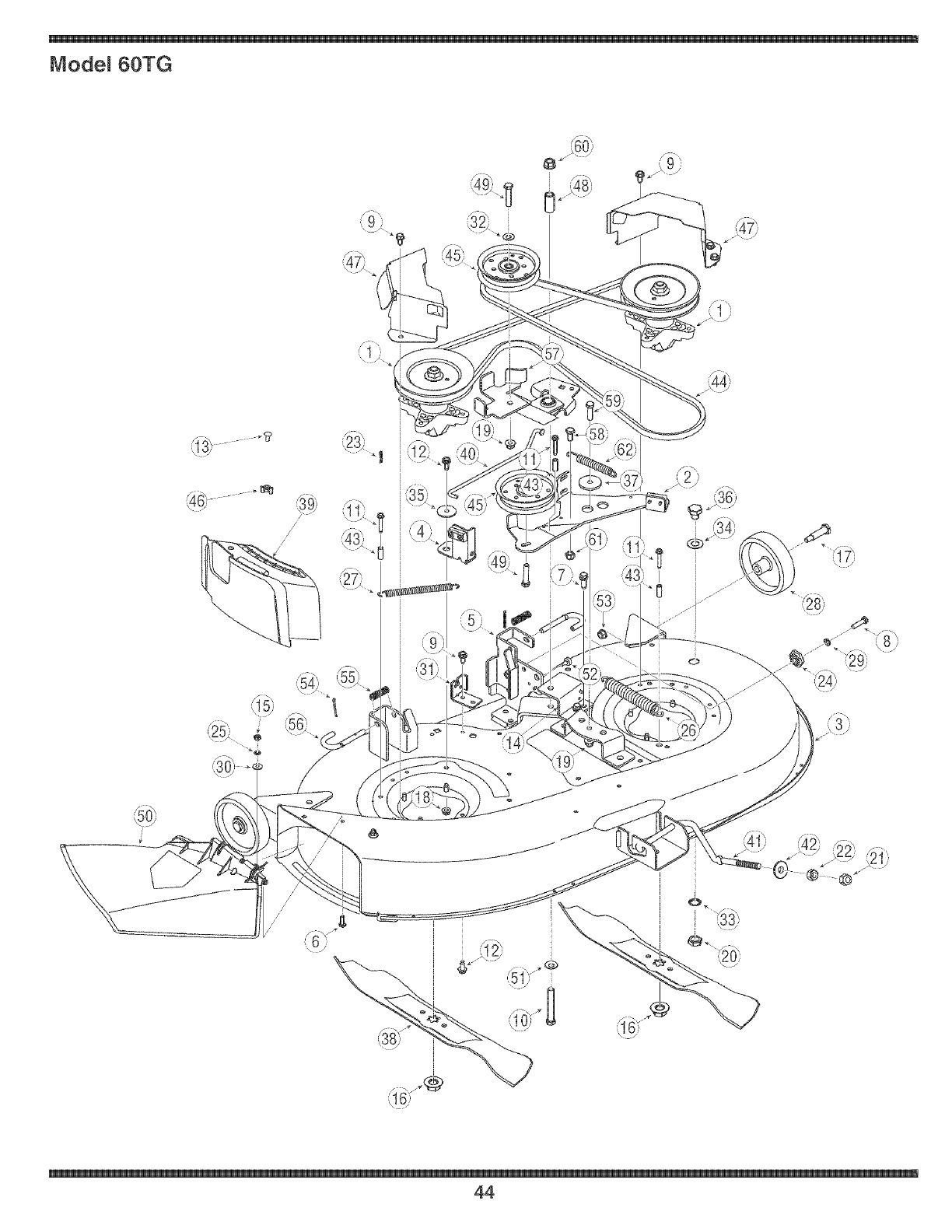
Mode_ 60TG
il 7}
/
/
//
//
44

Ref. Part No. Description
No.
1 618=0624 SpindleAssembly,Pul,6,23" Dia
2 683=04138A BrakeAssembly,Deck
3 683=04261 DeckShell,42"
4 683=04167 BrakeAssembly,Deck
5 683=0254B Brkt,Ass'y,Deck,HangerLH
6 710=3015 Screw,1/4=20,,75,Gr5
7 710=0654A Screw,3/8=16,1,00
8 710=0528 Screw,5/16=18,1,250
9 710=0726 Screw,5/16=12,0,750
10 710=0510 Screw,7/16=20,3,00,Gr5
11 710=0778 Screw,1/4=20,1,500
12 710=1260A Screw,5/16=18,,75
13 710=01341 CarriageScrew,, 1/4=20x ,62
14 783=05045 PivotSupportBracket
15 712=3006 Nut, Hex,1/4=20,Gr5
16 712=0417A Nut, Flange,5/8=18
17 738=0373 Screw,Shldr,,498x 1,53,3/8=16
18 712=04063 Nut, FlangeLock,5/16=18,GrF
19 712=04065 Nut, FlangeLock,3/8=16,GrF
20 712=0641 Nut, Hex,M16=1,5
21 712=3083 Nut, HexLock, 1/2=13,Gr8
22 712=0206 Nut, Hex,1/2=13,Gr5
23 714=0104 Pin,Cot, ,072Dia,x 1,13Lg
24 717=04074 Gear,DeckAdiustment
25 726=0233 Nut, Push,,25 IDx,50 OD
26 732=0459B Spring,Exten,, ,94 Dia,x 6,74
27 732=04287 Spring,Exten,, ,50 Dia,x 6,375
28 734=0973 Wheel,Deck5,0 x 1,38
29 736=0119 Washer,Lock,5/16
30 736=0270 Washer,Bell, ,265x,75x ,062
31 783=04740 DeckEngagementCableBracket
Ref. Part No. Description
No.
32 736=0300 Washer,Flat,,406x ,875x ,059
33 736=0760 Washer,Lock
34 737=04003C DeckWaterNozzle
35 738=04166 Spacer,Shoulder,,5000x,1475
36 721=04041 WaterNozzleAdapter
37 738=04162A Spacer,Shoulder,,8840x,190
38 742=0616A Blade,21,23",Star3=in=l
39 731=2363t MulchRug
40 747=04501 ControlRod,Brake
41 747=04269A Deck Rod,FrontAdiustable
42 748=04069 PivotCup,Deck Lift
43 750=0566A Spacer,,260x ,372x 1,030
44 754=04045 Belt,V=Type
45 756=04129 Idler Pulley,4,25"Dia,
46 712=3087t Wing Nut,1/4=20
47 783=04327A Cover,Belt,6,00 Dia,
48 750=04637 Spacr,,455 IDx ,680OD
49 710=0347 Screw,3/8=16x1,75
50 731=1032B ChuteAssembly,Discharge
51 736=0407 BellWasher,,45x 1,00x ,062
52 735=0271 Bumper
53 712=0431 FlangeLockNut, 3/8=16
54 714=0470 Cotter Pin
55 732=0306A Comp,Spring,,5310Dx 1,75Lg,
56 747=1116 Deck ReleaseRod
57 683=04252 Deck ldlerAssembly
58 710=0216 Screw,3/8-16x,75
59 710=3005 Screw,3/8=16x1,25
60 712=0459 FlangeLockNut, 7/16=20
61 712=3061 HexLockNut,3/8=24
62 732=0470A ExtensionSpring,,53 ODx 4,75
tIfEquipped
Fora properworking machine
Jse Factory Approved Parts.
V-belts are designed to
_ngageand disengage safely.
NOTE:Tractorfeaturesvaryby model NOTall partslistedaboveandpicturedonthe previouspagearestandard
equipment,
45
,,rderrepmocement
parts, call the Customer
_ Service Line at
!=800=648,6776'
www.troybilt.com. /

Use this page to make
notesandwritedown
importantinformation.
46

i
CAUFORNtA EMISSION CONTROL WARRANTY STATEMENT
YOUR WARRANTY R_GRTS AND OBUGATJONS
The CaliforniaAir ResourcesBoardandTroy-BiltLLCare pleasedtoexplainthe evaporativeemissioncontrolsystemwarrantyonyour 2006lawn mower.In
California,new lawnmowermust be designed,built and equippedto meetthe State'sstringentanti-smogstandards.Troy-BiltLLCmustwarrantthe EECSonyour
lawnmowerfor the periodof timelisted below providedtherehas beennoabuse,neglector impropermaintenanceof yourlawn mower.
YourEECSmayincludepartssuchas thecarburetor,fuel-injectionsystem,the ignitionsystem,catalyticconverter,fueltanks,fuel lines,fuelcaps,valves,
canisters,filters,vaporhoses,clamps,connectors,and otherassociatedemission-relatedcomponents.
Where a warrantable condition exists, Troy_Bilt LLC will repair your lawn mower at no cost to you including diagnosis, parts and labor.
MANUFACTURER'S WARRANTY COVERAGE:
Thisevaporativeemissioncontrolsystemis warrantedfor twoyears. If anyevaporativeemission-relatedpart onyour equipmentis defective,the partwill be
repairedor replacedbyTroy-BiltLLC.
OWNER'S WARRANTY RESPONSIBILIT_ES:
Asthe lawn mowerowner,you are responsiblefor performanceof the requiredmaintenancelistedin yourowner'smanual. Troy-BiltLLC recommendsthat you
retainall receiptscoveringmaintenanceon your lawnmower,butTroy-BiltLLCcannotdenywarrantysolelyfor the lackof receipts.
Asthe lawn mowerowner,you shouldhoweverbeawarethat Troy-BiltLLCmaydenyyou warrantycoverageifyour lawnmowerora part hasfailed duetoabuse,
neglect,or impropermaintenanceorunapprovedmodifications.
Youare responsiblefor presentingyourlawn mowerto Troy-BiltLLC'sdistributioncenterorservicecenteras soonasthe problemexists.The warranty repairs
shouldbecompletedin a reasonableamountoftime, notto exceed30 days.If youhavea questionregardingyour warrantycoverage,youshouldcontact Troy-Bilt
ServiceDepartmentat (866) 840-6483.
GENERAL EMISS_ONS WARRANTY COVERAGE:
Troy-BiltLLC warrantsto the ultimatepurchaserand eachsubsequentpurchaserthatthe lawn moweris: Designed,builtand equippedso asto conformwith all
applicableregulations;andfreefrom defectsin materialsand workmanshipthat causethe failure of a warrantedpart to beidenticalin all materialrespectsto that
partas describedinTroy-BiltLLC'sapplicationfor certification.
Thewarranty periodbeginsonthe datethe lawnmoweris deliveredto an ultimatepurchaserorfirst placedintoservice.Thewarranty periodistwoyears.
Subjecttocertainconditionsand exclusionsas statedbelow,the warrantyonemission-relatedparts isas follows:
1. Anywarrantedpart that isnot scheduledfor replacementas requiredmaintenanceinthe writteninstructionssupplied,is warrantedfor thewarranty period
statedabove. If thepart fails duringthe periodof warrantycoverage,the partwill be repairedor replacedbyTroy-BiltLLC accordingto subsection(4) below.
Anysuch partrepairedor replacedunderwarrantywill bewarrantedforthe remainderofthe period.
2. Anywarrantedpart that is scheduledonly for regular inspectioninthe writteninstructionssuppliediswarrantedfor thewarranty periodstatedabove.Any such
partrepairedorreplacedunderwarrantywill be warrantedfor the remainingwarrantyperiod.
3. Anywarrantedpart that isscheduledfor replacementas requiredmaintenanceinthe written instructionssuppliediswarrantedfor the periodof time beforethe
firstscheduledreplacementdatefor that part.If the part failsbeforethe firstscheduledreplacement,the partwill be repairedor replacedbyTroy-BiltLLCac-
cordingto subsection(4) below.Any suchpartrepairedor replacedunderwarrantywill bewarrantedforthe remainderof the periodpriorto thefirst scheduled
replacementpointfor the part.
4. Repairor replacementof any warrantedpart underthewarrantyprovisionshereinmustbe performedat a warrantystationat nochargeto theowner.
8. Notwithstandingthe provisionsherein,warrantyservicesor repairswill be providedat all of our distributioncentersthat arefranchisedto servicethe subject
enginesor equipment.
6. The lawnmowerowner willnot be chargedfor diagnosticlaborthat is directlyassociatedwithdiagnosisof a defective,emission-relatedwarrantedpart,
providedthat such diagnosticwork is performedat a warrantystation.
7. Troy-BiltLLCis liablefor damagesto otherengineor equipmentcomponentsproximatelycausedby a failureunderwarrantyof anywarrantedpart.
8. Throughoutthe lawnmowerwarrantyperiodstatedabove,Troy-BiltLLCwillmaintaina supplyof warrantedparts sufficientto meet the expecteddemandfor
suchparts.
9. Anyreplacementpart maybe usedinthe performanceof anywarrantymaintenanceor repairsand mustbe providedwithoutchargeto the owner.Suchusewill
not reducethe warrantyobligationsof Troy-BiltLLC.
10.Add-onor modifiedpartsthat are notexemptedbythe Air ResourcesBoardmaynot beused.Theuse of anynon-exemptedadd-onor modifiedpartsby the
ultimatepurchaserwillbe groundsfor disallowinga warrantyclaims.Troy-BiltLLC willnot be liableto warrantfailures of warrantedparts caused bythe use of a
non-exemptedadd-onor modifiedpart.
WARRANTED PARTS:
The repairor replacementof any warrantedpartotherwiseeligiblefor warrantycoveragemaybe excludedfromsuchwarrantycoverageifTroy-BiltLLCdemon-
stratesthat the lawnmowerhasbeenabused,neglected,or improperlymaintained,andthat suchabuse,neglect,or impropermaintenancewasthe directcauseof
theneedfor repairor replacementof the part.Thatnotwithstanding,any adjustmentof a componentthat hasa factoryinstalled,andproperlyoperating,adjust-
ment limitingdeviceisstill eligibleforwarrantycoverage.The followingemissionwarrantypartslist are covered:FuelLine, FuelLineClamps

MANUFACTURER'S LIMITED WARRANTY FOR
®
The limitedwarrantyset forthbelowis givenbyTroy_BiltLLCwithrespect
to newmerchandisepurchasedandusedin the UnitedStates,itsposses_
sionsandterritories.
"Troy_Bilt"warrantsthis productagainstdefectsinmaterialandworkmam
shipfor a periodof two(2)yearscommencingon thedate of original
purchaseandwill,at its option,repairorreplace,freeof charge,any part
foundto bedefectivein materialsor workmanship.This limitedwarranty
shallonly applyif this producthasbeenoperatedand maintainedin
accordancewiththe Operator'sManualfurnishedwiththe product,and
has notbeensubiectto misuse,abuse,commercialuse,neglect,accident,
impropermaintenance,alteration,vandalism,theft,fire,water,or damage
becauseof other perilor naturaldisaster.Damageresultingfromthe
installationor use ofany part,accessoryor attachmentnot approvedby
Troy_Biltfor use withtheproduct(s)coveredby this manualwill voidyour
warrantyas to any resultingdamage.
Normalwearpartsarewarrantedto befree fromdefectsinmaterialand
workmanshipfor aperiodof thirty (30)daysfromthedate of purchase.
Normalwearpartsinclude,butare notlimitedto itemssuchas: batteries,
belts,blades,bladeadapters,grassbags,riderdeckwheels,seats,snow
throwerskidshoes,shaveplates,augerspiralrubberandtires.
NOWTO OBTAIN SERVICE: Warranty service is available, WITH
PROOFOF PURCHASE,through your local authorizedservice
dealer. To locate the dealer in your area, check your Yellow Pages,
or contact Troy-Bilt LLC at RO. Box 361131,Cleveland, Ohio 44136-
0019, or can 1-866-840-6483 or 1-330-558-7220,or log on to our
Web site at www.troybilt.com.
This limitedwarrantydoesnot providecoverageinthe followingcases:
a. The engineor componentpartsthereof.Theseitemsmay
carrya separatemanufacturer'swarranty.Referto applicable
manufacturer'swarrantyfor termsandconditions.
b. Logsplitterpumps,valves,andcylindershaveaseparateone
yearwarranty.
c. Routinemaintenanceitemssuchas lubricants,filters,blade
sharpening,tune_ups,brakeadiustments,clutch adiustments,
deckadiustments,andnormaldeteriorationof the exteriorfinish
dueto use orexposure.
d. Servicecompletedbysomeoneotherthananauthorizedservice
dealer.
e. Troy_Biltdoesnot extendanywarrantyfor productssold or
exportedoutsideof the UnitedStates,its possessionsand
territories,exceptthosesold throughTroy_Bilt'sauthorized
channelsof exportdistribution.
f. Replacementpartsthatare notgenuineTroy_Biltparts.
g. Transportationchargesandservicecalls.
No impliedwarranty, includingany impliedwarranty of merchant°
ability of fitness for a particular purpose, applies after the applicable
period of express written warranty above as to the parts as identi-
fied. No other express warranty, whether written or oral, except as
mentioned above,given by any person or entity, includinga dealer or
retailer,with respect to any product, shall bind Troy-Bilt. During the
period of the warranty,the exclusive remedy is repair or replacement
of the product as set forth above.
The provisions as set forth inthis warranty providethe sole and
exclusive remedyarising from the sale. Troy-Bilt shall not be liable
for incidental or consequential loss or damage including, without
limitation, expenses incurred for substitute or replacement lawn care
services or for rental expenses to temporarily replace a warranted
product.
Somestatesdo not allowtheexclusionor limitationof incidentalor
consequentialdamages,or limitationson howlonganimpliedwarranty
lasts,so the aboveexclusionsor limitationsmaynotapplyto you.
In noeventshall recoveryof any kind begreaterthanthe amountof the
purchasepriceof the productsold.Alteration of safety features of the
product shall void this warranty. Youassumethe riskandliabilityfor
loss,damage,or injuryto youand yourpropertyand/or to othersandtheir
propertyarisingout of the misuseor inabilityto use the product.
This limitedwarrantyshall notextendto anyoneotherthanthe original
purchaseror to the personfor whomit waspurchasedas a gift.
HOWSTATELAW RELATESTO THiSWARRANTY:This limitedwar-
rantygh,'esyouspecificlegalrights,andyou mayalso haveother rights
whichvaryfromstateto state.
IMPORTANT:OwnermustpresentOriginalProofof Purchaseto obtain
warrantycoverage.
TROYBILT LLC, P.O. BOX 361131 CLEVELAM D, OHIO 44136-0019; Phone: 1(866} 840-6483, 1-330-558-7220
