Twinhead MPCT10L1 Tablet PC User Manual T10L UserMan Part 2
Twinhead International Corporation Tablet PC T10L UserMan Part 2
UserManual.wiki
>
Twinhead
>
MPCT10L1 User Manual
>
(T10L) UserMan-Part 2
Contents
1.
(T10L) UserMan-Part 1
2.
(T10L) UserMan-Part 2
(T10L) UserMan-Part 2
Navigation menu
Upload a User Manual
Namespaces
Wiki Guide
HTML
PDF
Info
Views
User Manual
Discussion / Help
Navigation
![29 How to use the Barcode Scanner: Please click on [TwMCA-App] icon shown on Desktop. Then click it to execute Barcode scanner software. Then select [Decode ON] button on the application software to turn on built-in barcode scanner. It will be ready to read when there is a red light beam emitting from the device, and complete the reading when the light is off. To stop barcode scanner, please press [Disconnect] button.. * Through software developed by ISV to define Barcode scanner function. (button on handle)](https://usermanual.wiki/Twinhead/MPCT10L1.T10L-UserMan-Part-2/User-Guide-1318321-Page-1.png)
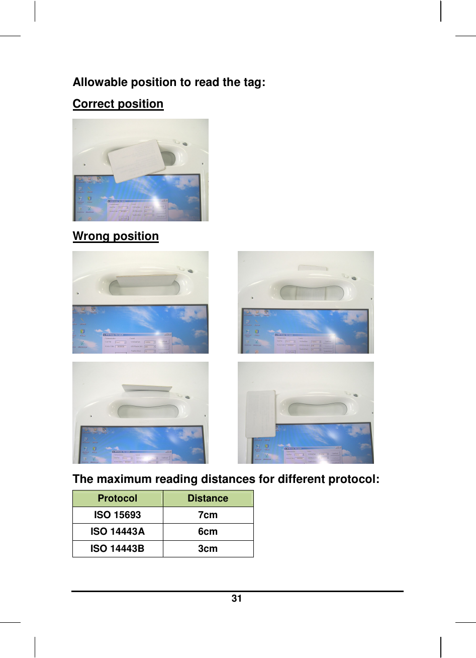
![30 Information about RFID reader The RFID reader is a compact contactless reader which supports Mifare® cards and ISO15693 (NOTE: Optional supports ISO14443A & ISO 14443B with non-healthcare standard) How to use the RFID reader: Please click on [TwMCA-App] program icon shown on Windows desktop to execute RFID reader software. Press [Connect] button on the application software to turn on built-in RFID reader, then put RFID card on the sensor area and press [Read] button. To stop RFID reader, please press [Disconnect] button. *Through software developed by ISV to define RFID function. (Button on the handle)](https://usermanual.wiki/Twinhead/MPCT10L1.T10L-UserMan-Part-2/User-Guide-1318321-Page-2.png)
![34 Information about 3G function Note: The system does not support 3G Voice features. The system provides 3G function (optional), please remove the SIM card cover. Then insert 3G SIM card into the slot. Attention: WLAN function will be auto turn-off when 3G function is on. Please click on [3G Watcher] program shown on Desktop to turn on 3G function. Please follow 3G Watcher Help Topics/ Wireless Data Connections/Manage profiles to create a profile first. After all settings are completed, click Connect to access Internet. User will find on Windows task bar. The indicator shows the received signal strength in dBm up to a maximum of five bars.. Please click 3G Watcher Tools/Turn Radio Off to stop connection.](https://usermanual.wiki/Twinhead/MPCT10L1.T10L-UserMan-Part-2/User-Guide-1318321-Page-6.png)
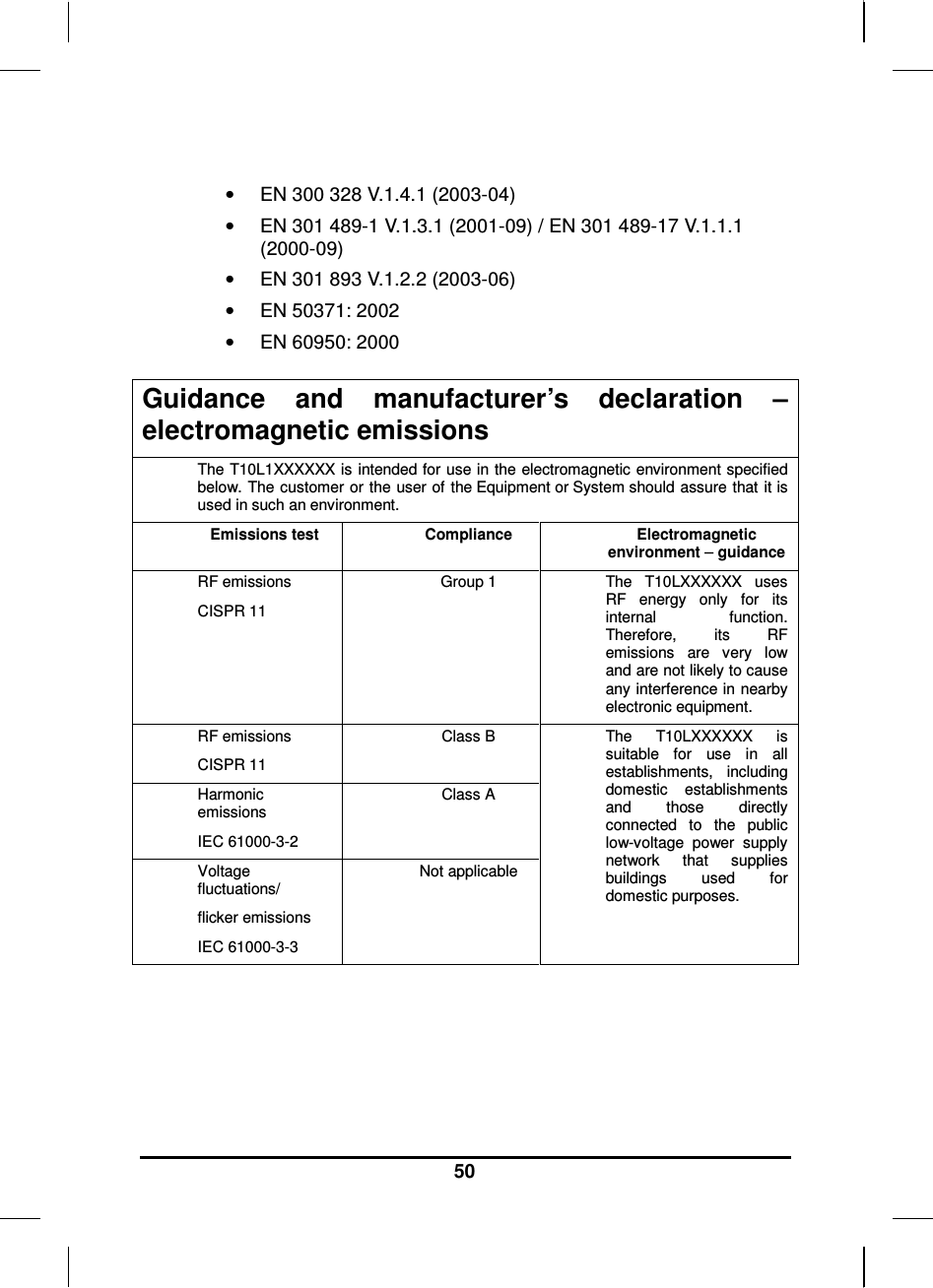
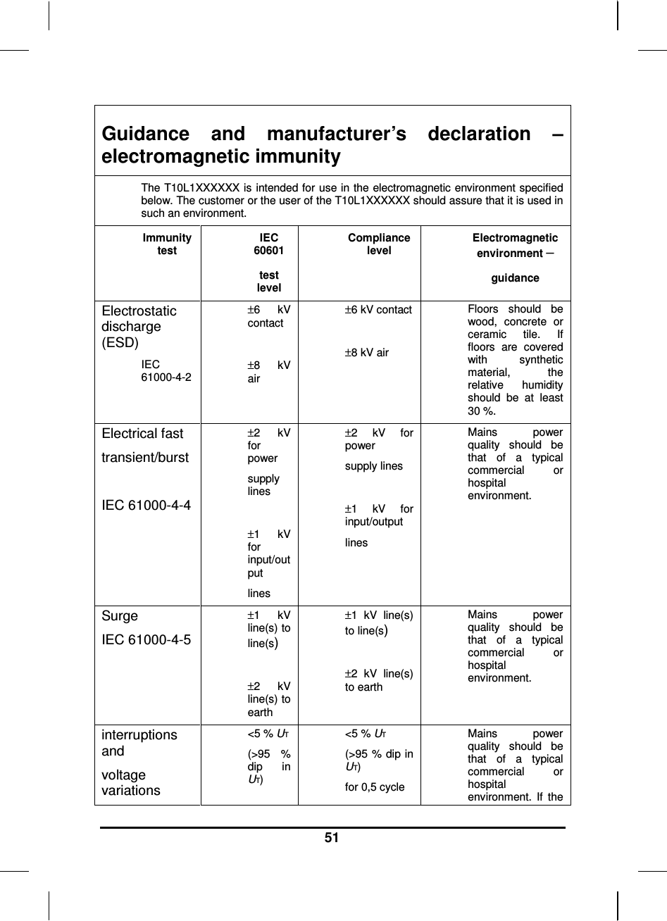
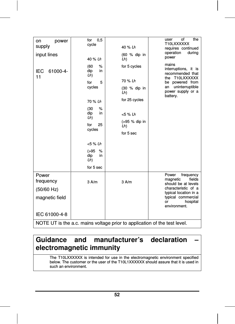
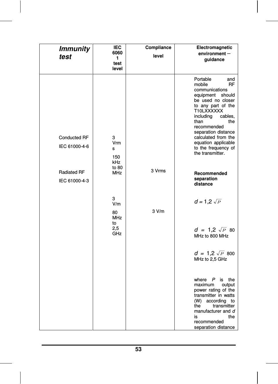
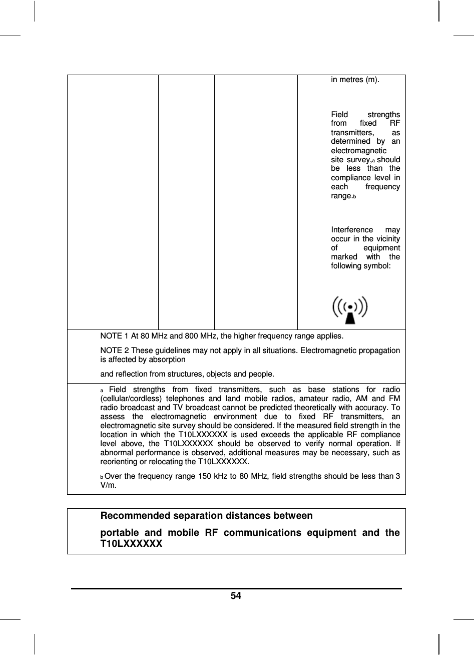
![55 The T10LXXXXXX is intended for use in an electromagnetic environment in which radiated RF disturbances are controlled. The customer or the user of the T10LXXXXXX can help prevent electromagnetic interference by maintaining a minimum distance between portable and mobile RF communications equipment (transmitters) and the T10LXXXXXX as recommended below, according to the maximum output power of the communications equipment. Separation distance according to frequency of transmitter m Rated maximum output power of transmitter W 150 kHz to 80 MHz d = 1,2 80 MHz to 800 MHz d = 1,2 800 MHz to 2,5 GHz d = 2,3 0,01 0,12 0,12 0,23 0,1 0,38 0,38 0,73 1 1,2 1,2 2,3 10 3,8 3,8 7,3 100 12 12 23 For transmitters rated at a maximum output power not listed above, the recommended separation distance d in metres (m) can be estimated using the equation applicable to the frequency of the transmitter, where P is the maximum output power rating of the transmitter in watts (W) according to the transmitter manufacturer. NOTE 1 At 80 MHz and 800 MHz, the separation distance for the higher frequency range applies. NOTE 2 These guidelines may not apply in all situations. Electromagnetic propagation is affected by absorption and reflection from structures, objects and people. Classification (clause 5): Class I equipment No applied part IP54 (for table PC), IPX0 (for adapter and docking station) No AP and APG Continuous operation ]](https://usermanual.wiki/Twinhead/MPCT10L1.T10L-UserMan-Part-2/User-Guide-1318321-Page-27.png)