Twinhead MPCT10L1 Tablet PC User Manual T10L UserMan Part 2
Twinhead International Corporation Tablet PC T10L UserMan Part 2
Twinhead >
Contents
- 1. (T10L) UserMan-Part 1
- 2. (T10L) UserMan-Part 2
(T10L) UserMan-Part 2
29
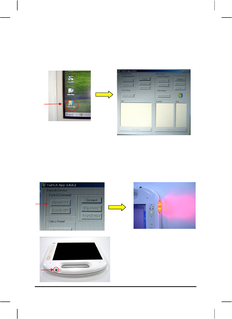
How to use the Barcode Scanner:
Please click on [TwMCA-App] icon shown on Desktop. Then click it to
execute Barcode scanner software.
Then select [Decode ON] button on the application software to turn on built-
in barcode scanner. It will be ready to read when there is a red light beam
emitting from the device, and complete the reading when the light is off. To
stop barcode scanner, please press [Disconnect] button..
* Through software developed by ISV
to define Barcode scanner function.
(button on handle)
30
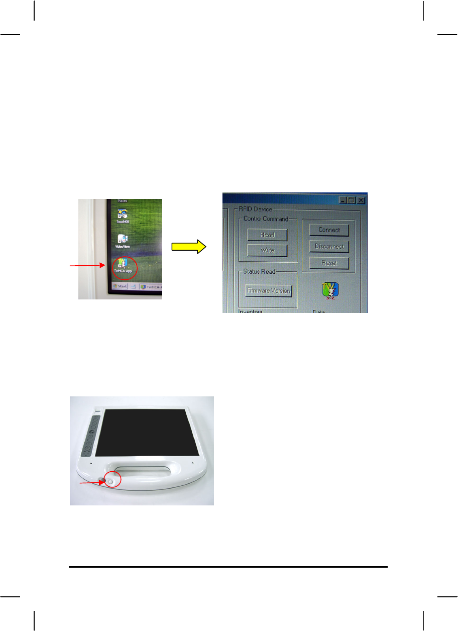
Information about RFID reader
The RFID reader is a compact contactless reader which supports Mifare®
cards and ISO15693 (NOTE: Optional supports ISO14443A & ISO 14443B
with non-healthcare standard)
How to use the RFID reader:
Please click on [TwMCA-App] program icon shown on Windows desktop to
execute RFID reader software.
Press [Connect] button on the application software to turn on built-in RFID
reader, then put RFID card on the sensor area and press [Read] button. To
stop RFID reader, please press [Disconnect] button.
*Through software developed by ISV
to define RFID function.
(Button on the handle)
31
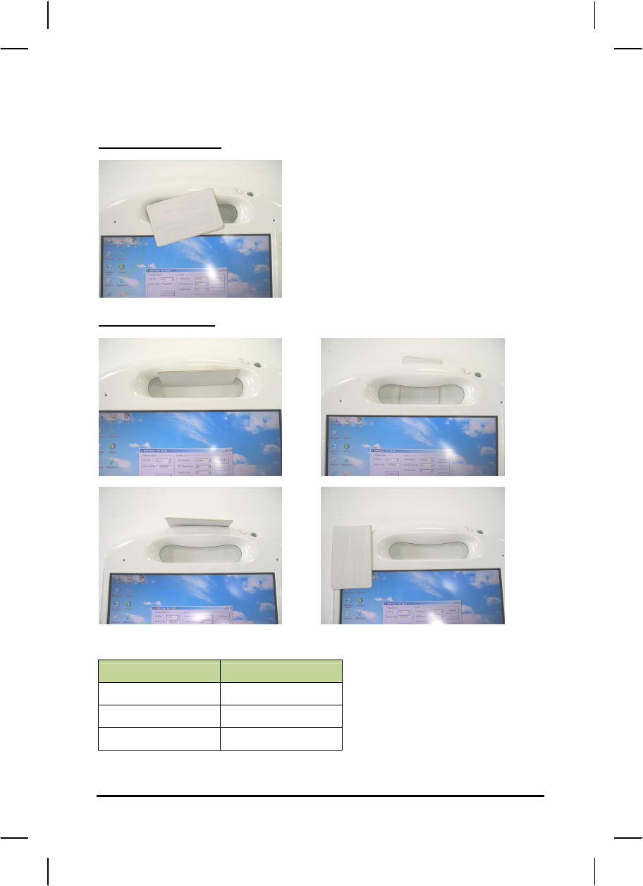
Allowable position to read the tag:
Correct position
Wrong position
The maximum reading distances for different protocol:
Protocol Distance
ISO 15693 7cm
ISO 14443A 6cm
ISO 14443B 3cm
32
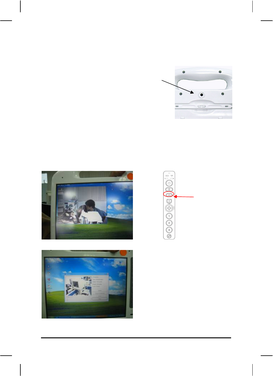
Information about Camera function
The camera lens is on the back of the MCA.
Features:
2 mega pixels resolution (1600 x 1200)
Support Auto Focus
How to use the Camera:
Click on the CAMERA button, it will pop up a preview screen, then press
the CAMERA button again to save the photo. The preview screen will
close after 10 sec automatically.
(camera capture button )

33
Communication Components
This system includes built-in Wireless LAN, Bluetooth and 3G functions:
Built-in Wireless Local Area Network
The built-in Wireless Local Area Network (WLAN) interface card can
provide a quick access without using cables for the connection to the
network equipments. ISM electric wave frequency band as
the transmission interface to set up the communications between the
host computer and other computers.
The way of processing communications through the WLAN interface
card is the same as that through Ethernet interface card. The
“Configuration Tool” is a Window application program. If users have a
computer equipped with the WLAN interface card, then users can use
it to set up the interface card and show the current configuration and
status.
Note: Contact your distributor for the information of upgrading the
wireless local area network.
34
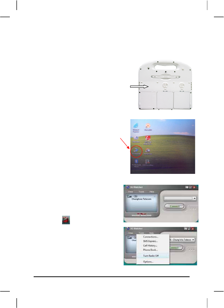
Information about 3G function
Note: The system does not support 3G Voice features.
The system provides 3G function
(optional), please remove the SIM card cover.
Then insert 3G SIM card into the slot.
Attention: WLAN function will be auto
turn-off when 3G function is on.
Please click on [3G Watcher] program
shown on Desktop to turn on 3G function.
Please follow 3G Watcher Help Topics/
Wireless Data Connections/Manage
profiles to create a profile first.
After all settings are completed, click
Connect to access Internet.
User will find on Windows task bar.
The indicator shows the received signal
strength in dBm up to a maximum of five
bars..
Please click 3G Watcher Tools/Turn
Radio Off to stop connection.
35
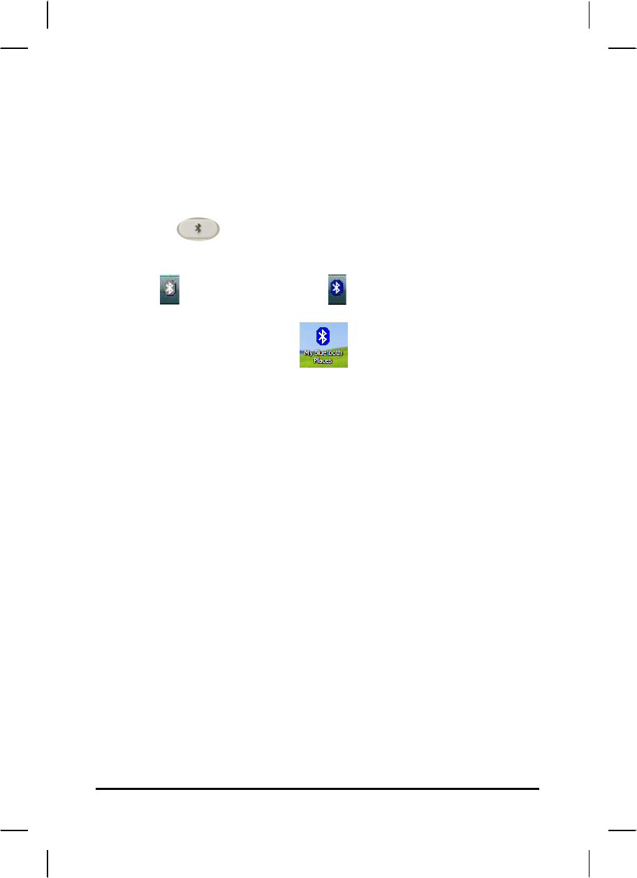
Information about Bluetooth function
A Bluetooth wireless technology is the ability to simultaneously handle both
data and voice transmissions. This enables users to enjoy a variety of
solutions such as hands-free headset for voice calls, printing and fax
capabilities, and synchronizing PDA, laptop, and mobile phone applications.
Please press hot key to turn on Bluetooth function.
User could check Bluetooth connection status from indicator on Windows
task bar. : Bluetooth disconnection : Bluetooth connection
Double click Bluetooth indicator or on Desktop to turn on
application program.

C
Ch
ha
ap
pt
te
er
r
3
3
M
Ma
ak
ki
in
ng
g
C
Co
on
nn
ne
ec
ct
ti
io
on
ns
s
37
Making Connections
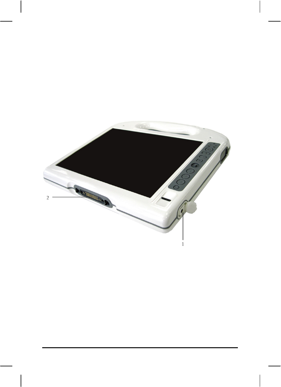
Right Side Connectors
1. DC-in Jack
Connect the power plug of the AC adapter to this jack.
2. Docking Station connector
The Connector is reserved for specific purpose which is used to
connect to its docking station.

C
Ch
ha
ap
pt
te
er
r
4
4
P
Po
ow
we
er
r
M
Ma
an
na
ag
ge
em
me
en
nt
t
39
Power Management
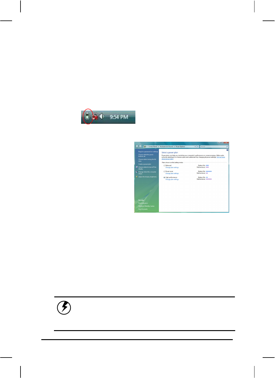
Checking the Battery Level
You can check the remaining battery power in the Windows® battery status
indicator located at the lower right-hand corner of the task tray. The Battery
Status icon only appears in the task tray while the unit is running on the
battery power but not while the unit is running off an external power source
through the AC adaptor.
Battery Power Indicator
Enter Monitoring Battery Power
There are two ways to
monitor how much power the
battery has left.
1. Click Start / Settings /
Control Panel / Power
Options, then click Power
Meter.
2. Moving the cursor to the
battery icon on the
taskbar is the simplest
way to check on battery
power status.
If you do not see the battery icon, enable it in Start / Settings /
Control Panel / Power Options. Choose the Advanced tab and click
“Always show icon on the taskbar.”
Low Battery Alarms
How your MCA responds to a low battery condition is set under Start /
Settings / Control Panel / Power Options / Alarms.
Two different power alarms can be enabled or disabled: the Low
Battery Alarm, and the Critical Battery Alarm.
Warning: When battery power is low, the battery
indicator will flash red, and the alarm will
display a warning on your screen. Take immediate
action, such as saving files or connecting to the
AC adapter, or data may be lost.
40
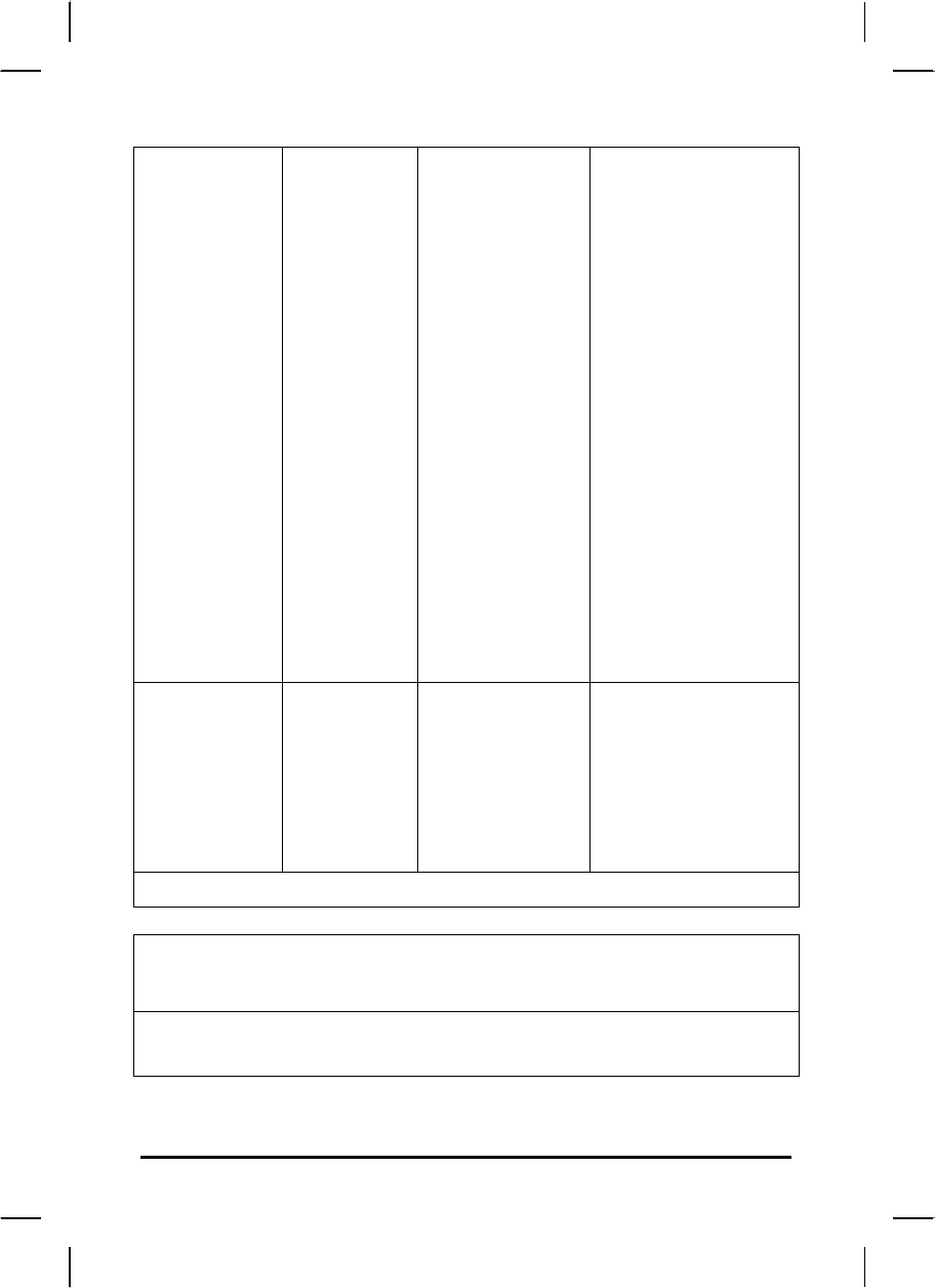
Battery Charging
When you use the AC adapter to connect your MCA to a power
outlet, the internal battery will automatically begin to recharge (get
charged first with battery 1, then goes to battery 2 when battery 1 is
fully charged, and the MCA is powered by the AC adaptor.) While the
battery is charging, the Battery Charge icon on the Indicator panel
will be active after 6~12 seconds. When the battery is fully charged,
the Battery Charge icon will turn off.
If your MCA is system off, a fully discharged battery will take about 2
hours to recharge. If your MCA is turned on and is not in suspend
mode, it twill take about 2~3 hours to recharge the battery. Refer to
the following table:
Charging
System On
(Under Screen Saver Mode) 2~3 hours
System Off (suspend to RAM) ~2 hours
To ensure the battery be charged to its Max. capacity, we suggest
you execute the following steps to refresh battery.
1. Fully charged the battery
2. Enter the BIOS set up menu and stay the unit untouched. Then,
the unit can fully discharge the battery to lowest level.
3. Fully discharge the unit to 100%. Then the battery learning is
done.
Note: The battery only can be charged in the condition of room
temp. 0-30 degree C. Other than this range, the battery may
not be fully charged. One fully charged Li-Ion battery can run
the MCA for approximately 2.25 hours.
41
When to Replace the Battery
Over time, the battery's capacity gradually decreases. We recommend that
you replace your battery when you notice that it begins to store significantly
less charge.
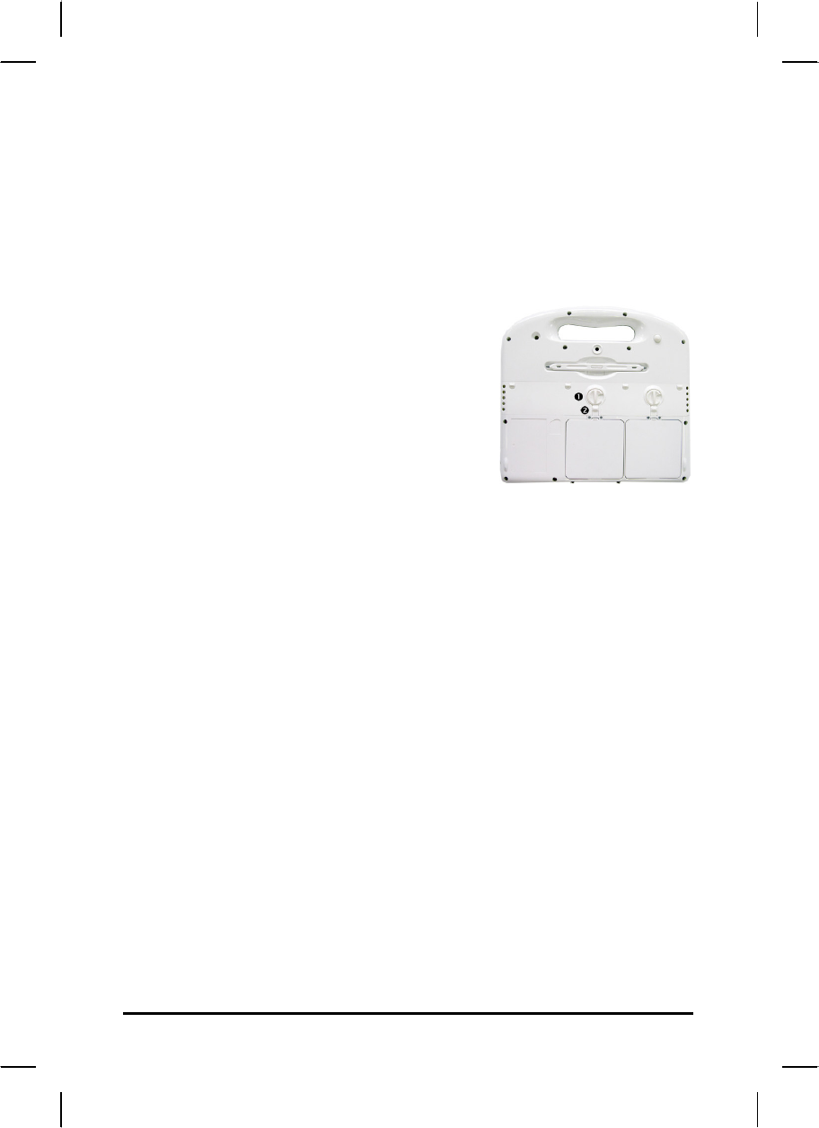
Changing the Battery
Change the main battery pack as
follows:
1. Turn off the MCA.
2. To replace the Battery, reposition the
latch and latch , then gently pull
the battery out of the battery bay.
3. Make sure the replacement battery is properly orientated. Then
insert the battery into the battery compartment. Check that the
latch locks back into position.
Heat Considerations
The MCA processor has been specially designed to consume little
power, and generates very little heat. However, working in a hot
environment, or working for long periods may raise the temperature.
If the temperature continues to rise, processor activity will be
reduced. You may notice a slight loss of performance when this
happens.

42
Chapter 5
D
Do
oc
ck
ki
in
ng
g
S
St
ta
at
ti
io
on
n
C
Co
on
nn
ne
ec
ct
to
or
rs
s
43
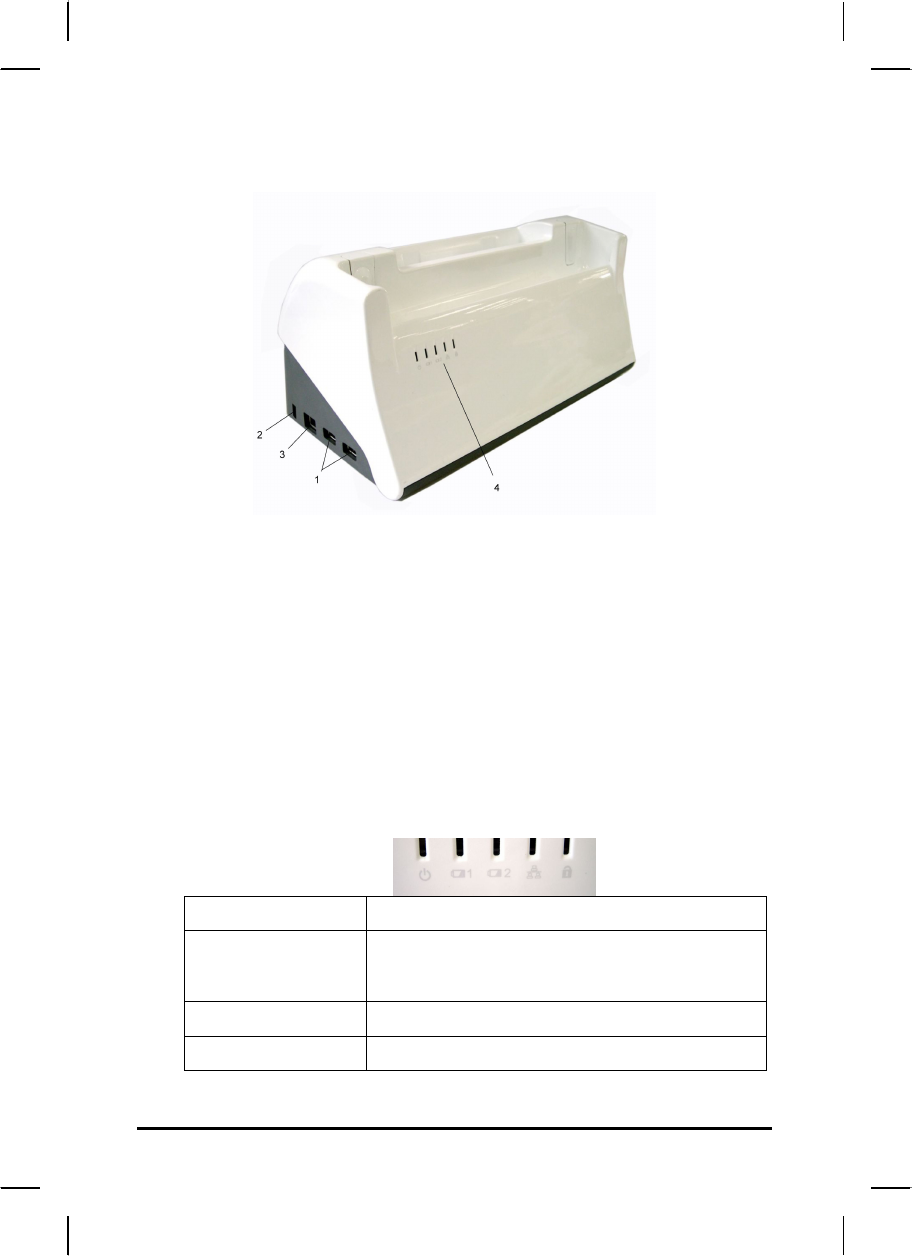
Docking Station Connectors – Front & left side
1. USB (Universal Serial Bus) Ports
The Universal Serial Bus (USB) is the latest standard for attaching
input devices, scanners, and other devices to a PC.
2. Kensington Slot
Kensington slot is part of an anti-theft system used as a deterrent to
prevent opportunist theft. It is used for attaching a lock-and-cable
apparatus.
3. LAN RJ-45 Jack
With the built-in Ethernet LAN combo, you can make LAN
connections without installing PC cards. Connection speed is 10/100
Mbps.
4. LED Indicator
Power Green when system is active
Battery 1 & 2 Green when battery is fully charged
Orange when battery is charging
LAN Green when the LAN is connected
Lock Green when the locking mechanism is on
44
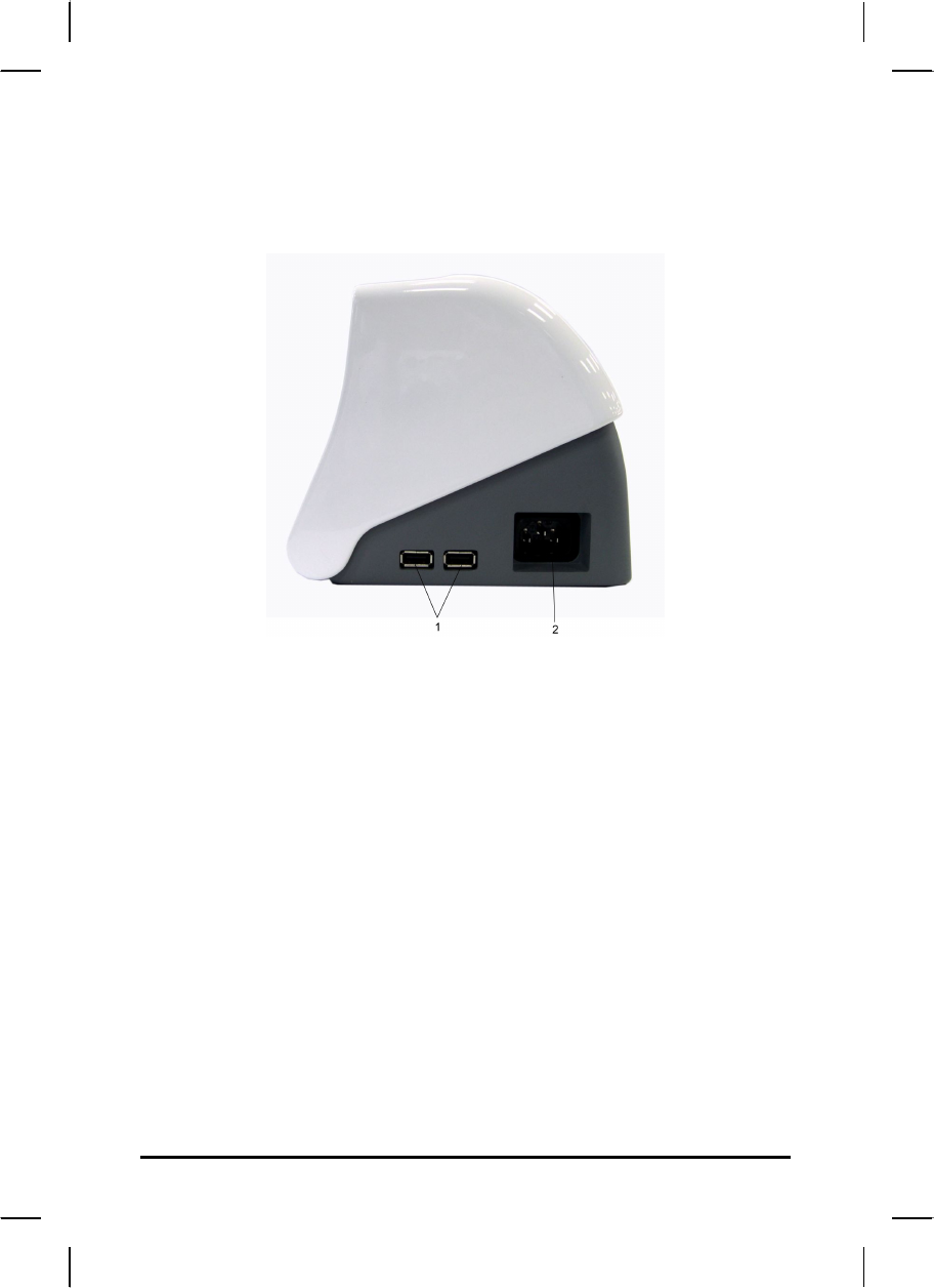
Docking Station Connectors – Right side
1. USB (Universal Serial Bus) Ports
The Universal Serial Bus (USB) is the latest standard for attaching
monitors, input devices, scanners, and other devices to a PC.
2. Power Cord Entry
Connect the power cord from the AC outlet to this entry.
There is a power adaptor embedded inside of the docking station
(Input:100V-240V,47Hz-63Hz, output: 78W , 18V).
45
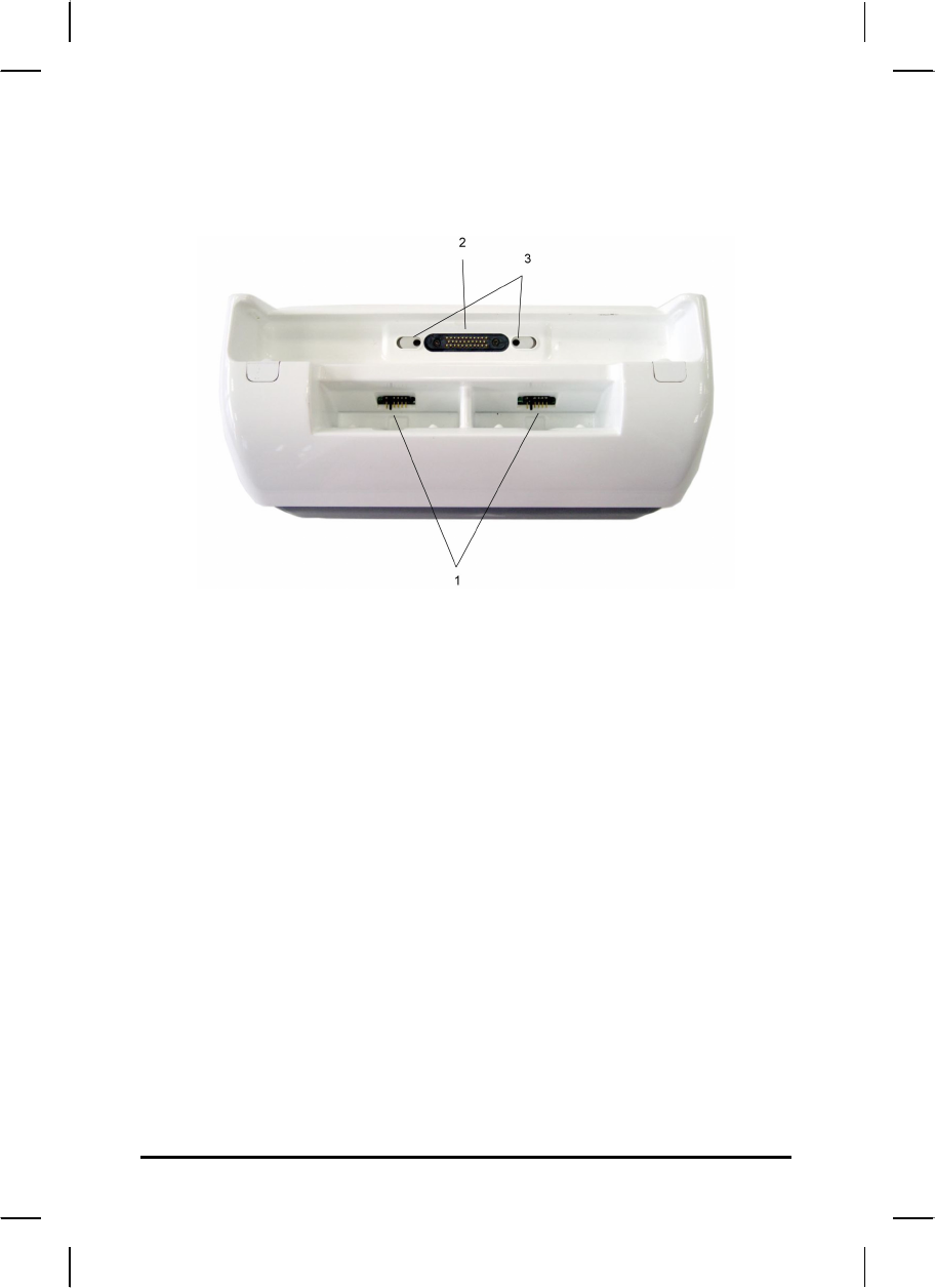
Docking Station Connectors – Top side
1. Battery charger
Provide 2 battery charging bays. The charging time may vary
depending on system and environmental temperature.
2. Host slot
The host is used to connect to your MCA.
3. Locking mechanism
An electronic lock to keep the unit locked on the dock.

46
Mechanical Specification
Mounting:
An optional bracket (VESA standard, hole pattern 75 x 75 mm) is
available when there is need to mount the docking station for
different purposes.
Tilt:
To provide an optimal viewing performance while user is in different
operating position, this docking station is capable of adjusting the tilt
angle, and it ranges from 5° forwardly, and 25° backwardly.

A
Ap
pp
pe
en
nd
di
ix
x
A
A
S
St
ta
at
te
em
me
en
nt
ts
s

48
Statements
Federal Communications Commission Statement
This equipment has been tested and found to comply with the limits
for a Class B digital device, pursuant to Part 15 of the FCC Rules.
These limits are designed to provide reasonable protection against
harmful interference in a residential installation. This equipment
generates, uses, and can radiate radio frequency energy and, if not
installed and used in accordance with the instructions, may cause
harmful interference to radio communications. However, there is no
guarantee that interference will not occur in a particular installation. If
this equipment does cause harmful interference to radio or television
reception, which can be determined by turning the equipment off and
on, the user is encouraged to try to correct the interference by one or
more of the following measures:
1. Reorient or relocate the receiving antenna.
2. Increase the separation between the equipment and the receiver.
3. Connect the equipment into an outlet on a circuit different from
that to which the receiver is connected.
4. Consult the dealer or an experienced radio/TV technician for
help.
Shielded interconnect cables and shielded AC power cable must be
employed with this equipment to insure compliance with the pertinent
RF emission limits governing this device. Changes or modifications
not expressly approved by the system's manufacturer could void the
user's authority to operate the equipment.
CAUTION
Any changes or modifications not expressly approved by the party
responsible for compliance could void the user's authority to operate
the equipment.
49
RF exposure warning
This equipment must be installed and operated in accordance with
provided instructions and must not be co-located or operating in
conjunction with any other antenna or transmitter. End-users and
installers must be provide with antenna installation instructions and
transmitter operating conditions for satisfying RF exposure
compliance.
Max. SAR Measurement (1g)
WLAN: 0.189W/kg
GSM: 0.952 W/kg
WCDMA: 1.24 W/kg
CDMA: 1.04W/kg
Declaration of Conformity
This device complies with part 15 of the FCC rules. Operation is
subject to the following conditions:
• This device may not cause harmful interference
• This device must accept any interference received, including
interference that may cause undesired operation.
European Notice
CE Declaration of Conformity
For the following equipment: Tablet built-in 802.11/b/g/n WLAN
module
Is herewith confirmed to comply with the requirements set out in the
Council Directive on the Approximation of the Laws of the Member
States relating to Electromagnetic Compatibility (89/336/EEC), Low-
voltage Directive (73/23/EEC) and the Amendment Directive
(93/68/EEC), the procedures given in European Council Directive
99/5/EC and 89/3360EEC.
The equipment was passed. The test was performed according to the
following European standards:
50
• EN 300 328 V.1.4.1 (2003-04)
• EN 301 489-1 V.1.3.1 (2001-09) / EN 301 489-17 V.1.1.1
(2000-09)
• EN 301 893 V.1.2.2 (2003-06)
• EN 50371: 2002
• EN 60950: 2000
Guidance and manufacturer’s declaration –
electromagnetic emissions
The T10L1XXXXXX is intended for use in the electromagnetic environment specified
below. The customer or the user of the Equipment or System should assure that it is
used in such an environment.
Emissions test Compliance Electromagnetic
environment – guidance
RF emissions
CISPR 11
Group 1 The T10LXXXXXX uses
RF energy only for its
internal function.
Therefore, its RF
emissions are very low
and are not likely to cause
any interference in nearby
electronic equipment.
RF emissions
CISPR 11
Class B
Harmonic
emissions
IEC 61000-3-2
Class A
Voltage
fluctuations/
flicker emissions
IEC 61000-3-3
Not applicable
The T10LXXXXXX is
suitable for use in all
establishments, including
domestic establishments
and those directly
connected to the public
low-voltage power supply
network that supplies
buildings used for
domestic purposes.
51
Guidance and manufacturer’s declaration –
electromagnetic immunity
The T10L1XXXXXX is intended for use in the electromagnetic environment specified
below. The customer or the user of the T10L1XXXXXX should assure that it is used in
such an environment.
Immunity
test
IEC
60601
test
level
Compliance
level
Electromagnetic
environment –
guidance
Electrostatic
discharge
(ESD)
IEC
61000-4-2
±6 kV
contact
±8 kV
air
±6 kV contact
±8 kV air
Floors should be
wood, concrete or
ceramic tile. If
floors are covered
with synthetic
material, the
relative humidity
should be at least
30 %.
Electrical fast
transient/burst
IEC 61000-4-4
±2 kV
for
power
supply
lines
±1 kV
for
input/out
put
lines
±2 kV for
power
supply lines
±1 kV for
input/output
lines
Mains power
quality should be
that of a typical
commercial or
hospital
environment.
Surge
IEC 61000-4-5
±1 kV
line(s) to
line(s)
±2 kV
line(s) to
earth
±1 kV line(s)
to line(s)
±2 kV line(s)
to earth
Mains power
quality should be
that of a typical
commercial or
hospital
environment.
interruptions
and
voltage
variations
<5 % UT
(>95 %
dip in
UT)
<5 % UT
(>95 % dip in
UT)
for 0,5 cycle
Mains power
quality should be
that of a typical
commercial or
hospital
environment. If the
52
on power
supply
input lines
IEC 61000-4-
11
for 0,5
cycle
40 % UT
(60 %
dip in
UT)
for 5
cycles
70 % UT
(30 %
dip in
UT)
for 25
cycles
<5 % UT
(>95 %
dip in
UT)
for 5 sec
40 % UT
(60 % dip in
UT)
for 5 cycles
70 % UT
(30 % dip in
UT)
for 25 cycles
<5 % UT
(>95 % dip in
UT)
for 5 sec
user of the
T10LXXXXXX
requires continued
operation during
power
mains
interruptions, it is
recommended that
the T10LXXXXXX
be powered from
an uninterruptible
power supply or a
battery.
Power
frequency
(50/60 Hz)
magnetic field
IEC 61000-4-8
3 A/m
3 A/m
Power frequency
magnetic fields
should be at levels
characteristic of a
typical location in a
typical commercial
or hospital
environment.
NOTE UT is the a.c. mains voltage prior to application of the test level.
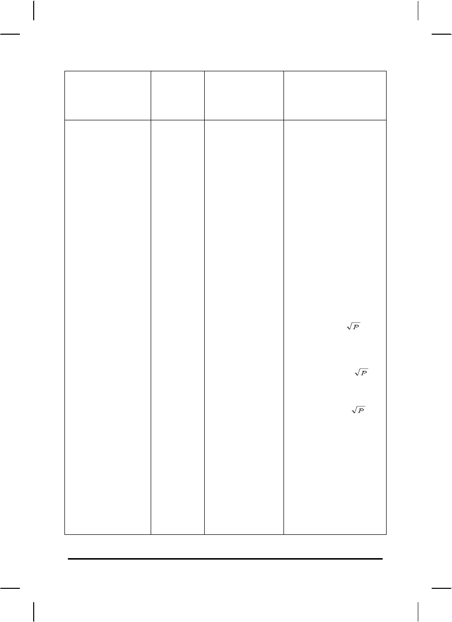
Guidance and manufacturer’s declaration –
electromagnetic immunity
The T10LXXXXXX is intended for use in the electromagnetic environment specified
below. The customer or the user of the T10L1XXXXXX should assure that it is used in
such an environment.
53
Immunity
test
IEC
6060
1
test
level
Compliance
level
Electromagnetic
environment –
guidance
Conducted RF
IEC 61000-4-6
Radiated RF
IEC 61000-4-3
3
Vrm
s
150
kHz
to 80
MHz
3
V/m
80
MHz
to
2,5
GHz
3 Vrms
3 V/m
Portable and
mobile RF
communications
equipment should
be used no closer
to any part of the
T10LXXXXXX
including cables,
than the
recommended
separation distance
calculated from the
equation applicable
to the frequency of
the transmitter.
Recommended
separation
distance
d = 1,2
d = 1,2 80
MHz to 800 MHz
d = 1,2 800
MHz to 2,5 GHz
where P is the
maximum output
power rating of the
transmitter in watts
(W) according to
the transmitter
manufacturer and d
is the
recommended
separation distance
54
in metres (m).
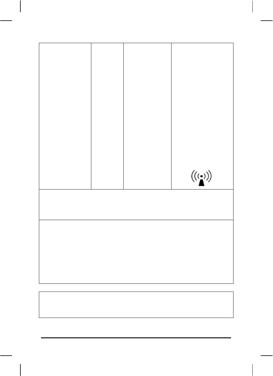
Field strengths
from fixed RF
transmitters, as
determined by an
electromagnetic
site survey,a should
be less than the
compliance level in
each frequency
range.b
Interference may
occur in the vicinity
of equipment
marked with the
following symbol:
NOTE 1 At 80 MHz and 800 MHz, the higher frequency range applies.
NOTE 2 These guidelines may not apply in all situations. Electromagnetic propagation
is affected by absorption
and reflection from structures, objects and people.
a Field strengths from fixed transmitters, such as base stations for radio
(cellular/cordless) telephones and land mobile radios, amateur radio, AM and FM
radio broadcast and TV broadcast cannot be predicted theoretically with accuracy. To
assess the electromagnetic environment due to fixed RF transmitters, an
electromagnetic site survey should be considered. If the measured field strength in the
location in which the T10LXXXXXX is used exceeds the applicable RF compliance
level above, the T10LXXXXXX should be observed to verify normal operation. If
abnormal performance is observed, additional measures may be necessary, such as
reorienting or relocating the T10LXXXXXX.
b Over the frequency range 150 kHz to 80 MHz, field strengths should be less than 3
V/m.
Recommended separation distances between
portable and mobile RF communications equipment and the
T10LXXXXXX
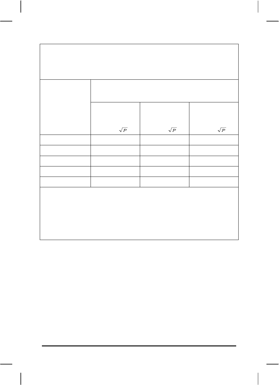
55
The T10LXXXXXX is intended for use in an electromagnetic environment in which
radiated RF disturbances are controlled. The customer or the user of the
T10LXXXXXX can help prevent electromagnetic interference by maintaining a
minimum distance between portable and mobile RF communications equipment
(transmitters) and the T10LXXXXXX as recommended below, according to the
maximum output power of the communications equipment.
Separation distance according to frequency of
transmitter
m
Rated
maximum
output
power of
transmitter
W
150 kHz to
80 MHz
d = 1,2
80 MHz to
800 MHz
d = 1,2
800 MHz to
2,5 GHz
d = 2,3
0,01 0,12 0,12 0,23
0,1 0,38 0,38 0,73
1 1,2 1,2 2,3
10 3,8 3,8 7,3
100 12 12 23
For transmitters rated at a maximum output power not listed above, the recommended
separation distance d in metres (m) can be estimated using the equation applicable to
the frequency of the transmitter, where P is the maximum output power rating of the
transmitter in watts (W) according to the transmitter manufacturer.
NOTE 1 At 80 MHz and 800 MHz, the separation distance for the higher frequency
range applies.
NOTE 2 These guidelines may not apply in all situations. Electromagnetic propagation
is affected by absorption and reflection from structures, objects and people.
Classification (clause 5):
Class I equipment
No applied part
IP54 (for table PC), IPX0 (for adapter and docking station)
No AP and APG
Continuous operation
]
56
Regulatory statement (R&TTE / WLAN IEEE 802.11b
& 802.11g)
European standards dictate maximum radiated transmit power of
100mW EIRP and frequency range 2.400-2.4835GHz; In France, the
equipment must be restricted to the 2.4465-2.4835GHz frequency
range and must be restricted to indoor use.
Safety Compliance
Safety for Canada
CAN/CSA C22.2 No 60950-1-03
Battery Disposal
THIS PRODUCT CONTAINS A LITHIUM-ION OR NICKEL-METAL
HYDRIDE BATTERY. IT MUST BE DISPOSED OF PROPERLY.
CONTACT LOCAL ENVIRONMENTAL AGENCIES FOR
INFORMATION ON RECYCLING AND DISPOSAL PLANS IN YOUR
AREA.
WEEE Symbol
The WEEE symbol, indicating separate collection for WEEE- Waste of
electrical and electronic equipment, consists of the crossed-out
wheeled bin, as shown below.

57
CAUTION FOR ADAPTER
THIS MCA IS FOR USE WITH MODEL NO. 0335A2065, 0335C2065,
JWM180KA1800F02.
BATTERY CAUTION
DANGER OF EXPLOSION IF BATTERY IS INCORRECTLY REPLACED.
REPLACE ONLY WITH THE SAME OR EQUIVALENT TYPE RECOMMENDED BY
THE MANUFACTURER. DISPOSE OF USED BATTERIES ACCORDING TO THE
MANUFACTURER'S INSTRUCTIONS.
For LPD
“Operation is subject to the following two conditions: (1) this device
may not cause interference, and (2) this device must accept any
interference, including interference that may cause undesired
operation of the device.”
W/detachable antenna
“To reduce potential radio interference to other users, the antenna
type and its gain should be so chosen that the equivalent
isotropically radiated power (EIRP) is not more than that required for
successful communication.”
Regulatory Information
Intel( R) Wireless Link 1000
Intel(R) Wireless WiFi Link 1000
Information for the user

58
Regulatory Information
Intel(R) Wireless WiFi Link 1000
The information in the document applies to the following products:
Tri-mode Wireless LAN adaptors (802.11b/802.11g/802.11n)
Intel(R) Wireless WiFi Link 1000 (model 112BNMMW)
Note: Due to the evolving state of regulations and standards in
the Wireless LAN field (IEEE 802.11 and similar standards), the
information provided herein is subject to change. Intel
Corporation assumes no responsibility for errors or omissions in
this document. Nor does Intel make any commitment to update
the information contained herein,
Information for the user
Safety Notices
USA-FCC and FAA
59
The FCC with its action in ET Docket 96-8 has adopted a safety standard for human exposure
th radio frequeccy(RF) electromagnetic energy emitted by FCC certified equiption. The Intel(R)
Wireless WiFi Link 1000 adapter meet Human Exposure limits found in OET Bulletin 65,
ssupplement C, 2001, and ANSI/IEEE C95.1,1992. Proper operation of the radio according to
the instructions found in this manual will result in exposure substantially below the FCC’s
recommanded limits
60
MANUFACTURED BY
TWINHEAD INTERNATIONAL CORP.
10F, 550 RUEIGUANG ROAD.
NEIHU, TAIPEI, TAIWAN 11492, R.O.C.