UTC Fire and Security Americas WEDGE180 IR Network Camera User Manual
UTC FIRE & SECURITY AMERICAS CORPORATION, INC IR Network Camera
UserManual.wiki
>
UTC Fire and Security Americas
>
WEDGE180 User Manual
User Manual
Navigation menu
Upload a User Manual
Namespaces
Wiki Guide
HTML
PDF
Info
Views
User Manual
Discussion / Help
Navigation

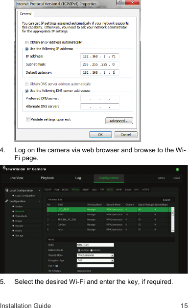
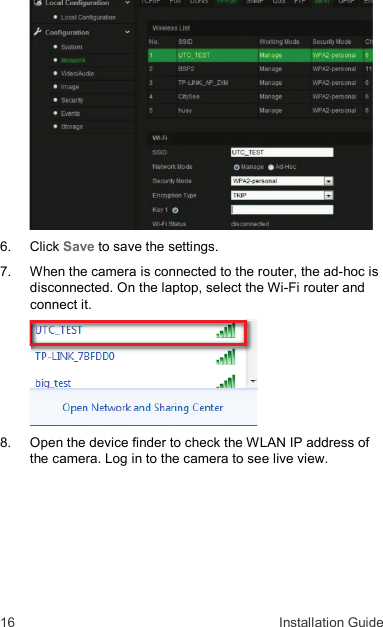
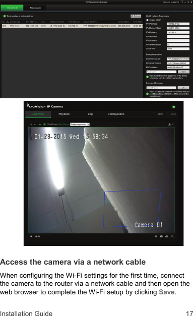
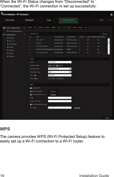
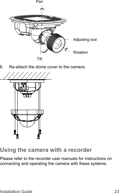
![22 Installation Guide 4. Mount the camera base to the converter pan or mounting surface, depending on the installation. 5. Use the supplied lens alignment tool to adjust the pan [±30°], tilt [0 to 80°], and rotation direction [0 to 360°].](https://usermanual.wiki/UTC-Fire-and-Security-Americas/WEDGE180/User-Guide-2696629-Page-23.png)