UTStarcom Telecom 6011 Wireless Access Point User Manual
UTStarcom Telecom Co., Ltd. Wireless Access Point
Contents
- 1. user manual
- 2. antenna installation guide
user manual

WA6011/6012 Outdoor AP
Access Point
ADMINISTRATOR GUIDE
Release: 1.0
Doc. Code: L3 JA01 2500 01 011 00
UTStarcom Inc.
Copyright © 2004 UTStarcom Inc. All rights reserved.
No part of this documentation may be reproduced in any form or by any
means or used to make any derivative work (such as translation,
transformation, or adaptation) without prior, express and written permission
from UTStarcom Inc.
UTStarcom Inc. reserves the right to revise this documentation and to make
changes in content from time to time without obligation on the part of
UTStarcom Inc. to provide notification of such revision or changes.
UTStarcom Inc. provides this documentation without warranty of any kind,
implied or expressed, including but not limited to, the implied warranties of
merchantability and fitness for a particular purpose. UTStarcom may make
improvements or changes in the product(s) and/or the program(s) described
in this documentation at any time.
UNITED STATES GOVERNMENT LEGENDS:
If you are a United States government agency, then this documentation and
the software described herein are provided to you subject to the following:
United States Government Legend: All technical data and computer
software is commercial in nature and developed solely at private expense.
Software is delivered as Commercial Computer Software as defined in
DFARS 252.227-7014 (June 1995) or as a commercial item as defined in
FAR 2.101(a) and as such is provided with only such rights as are provided
in UTStarcom's standard commercial license for the Software. Technical
data is provided with limited rights only as provided in DFAR 252.227-7015
(Nov 1995) or FAR 52.227-14 (June 1987), whichever is applicable. You
agree not to remove or deface any portion of any legend provided on any
licensed program or documentation contained in, or delivered to you in
conjunction with, this User Guide.
UTStarcom, the UTStarcom logo, PAS, mSwitch, Airstar, WACOS, Netman,
Total Control, and CommWorks are registered trademarks of UTStarcom Inc.
and its subsidiaries. The UTStarcom name, AN-2000, and the CommWorks
logo are trademarks of UTStarcom Inc. and its subsidiaries.
Any rights not expressly granted herein are firmly reserved.

WA3001-S Access Point User Guide
Contents
About This Guide.............................................................................................1
Introduction...........................................................................................................1
Conventions..........................................................................................................1
Notice ...............................................................................................................1
Text...................................................................................................................1
Figures and Screen Captures ..........................................................................2
Related Documentation........................................................................................2
1 Overview .................................................................................................3
Product Front View...............................................................................................3
Product Features..................................................................................................3
Network Topology.................................................................................................4
AP Mode...........................................................................................................4
Point To Point Mode (P2P)...............................................................................4
Point To Multi-Point Mode (M2MP)..................................................................5
2 Hardware Installation.............................................................................7
Package Contents ................................................................................................7
Interface Description.............................................................................................8
Product Label Description ....................................................................................9
电缆连接 Cable Connection ...............................................................................10
3 Web-based Configuration Introduction..............................................13
Login AP.............................................................................................................13
Web Configuration User Interface......................................................................14
Button Description ..............................................................................................15
4 Web-based Configuration....................................................................17
Guide Configuration ...........................................................................................17
Basic Configuration ............................................................................................21
AP Mode Configuration ..................................................................................21
Wireless Port1/Wireless Port2 Configuration.................................................21
DHCP Server Configuration ...........................................................................24
WAN Interface Configuration (WA6011) ........................................................26
WAN Interface Configuration (WA6012) ........................................................28
ADSL Configuration (WA6012/Bridge Mode).................................................29
LAN Interface Configuration...........................................................................29
Advanced Configuration.....................................................................................30

ii
User Guide WA3001-S Access Point
Wireless Port1 Configuration/Wireless Port2 Configuration ..........................30
RADIUS Client Configuration .........................................................................32
Authentication.................................................................................................33
Subscriber Configuration................................................................................36
ARP Configuration..........................................................................................37
Route Configuration .......................................................................................37
NAT Configuration..........................................................................................38
Isolation & Filter Configuration .......................................................................39
MAC Table Configuration...............................................................................40
VLAN Configuration........................................................................................41
System Configuration .........................................................................................41
System Information ........................................................................................42
Change Password..........................................................................................42
Web Management Filter.................................................................................42
SNMP Configuration.......................................................................................43
File System Management...............................................................................44
Statistic Information............................................................................................45
Wireless Port (WA6011).................................................................................45
ADSL Statistic Information (WA6012)............................................................46
WAN/LAN Interface........................................................................................47
DHCP Server..................................................................................................48
DHCP Relay ...................................................................................................48
RADIUS Client................................................................................................48
ARP ................................................................................................................49
Route..............................................................................................................49
Online User ....................................................................................................49
MAC Address .................................................................................................50
5 Typical Configuration Examples.........................................................51
AP in Bridge Mode..............................................................................................51
AP in Router Mode .............................................................................................54
AP in P2P Mode .................................................................................................56
6 Term and Acronym List .......................................................................59
1 Technical Specification .......................................................................61

iii
WA3001-S Access Point User Guide
List of Tables
Table 1 Interface Description on Side anel (I)................................................................8
Table 2 Label Description...............................................................................................9
Table 3 Configuration Description Table (WA6011) ....................................................15
Table 4 DHCP Server Parameter Description..............................................................25
Table 5 Wireless Port Parameters Description ............................................................30
Table 6 802.1x Authentication Config Parameter Specification...................................34

iv
User Guide WA3001-S Access Point
List of Figures
Figure 1 WA6011/6012 Front View................................................................................3
Figure 2 Network Topology in AP Mode........................................................................4
Figure 3 Network Topology in P2P Mode......................................................................5
Figure 4 WA6011 Network Topology in P2MP Mode....................................................5
Figure 5 WA6011/6012 Side View (I) ............................................................................8
Figure 6 WA6011/6012 Side Panel (II)..........................................................................9
Figure 7 WA6012 Bottom View......................................................................................9
Figure 8 Logon Window...............................................................................................14
Figure 9 Web Configuration UI (English).....................................................................14
Figure 10 Web Configuration UI (Chinese) .................................................................14
Figure 11 Buttons.........................................................................................................15
Figure 12 AP Reboot Prompt Window.........................................................................16
Figure 13 Guide Configuration Window.......................................................................17
Figure 14 AP Mode Setting Window............................................................................18
Figure 15 DHCP Configuration Window ......................................................................18
Figure 16 LAN Port Configuration................................................................................19
Figure 17 Wireless Port Configuration.........................................................................19
Figure 18 Configuration Completed.............................................................................20
Figure 19 WAN Port Configuration ..............................................................................20
Figure 20 AP Mode Configuration ...............................................................................21
Figure 21 Prompt Window after Apply AP Mode Changes..........................................21
Figure 22 Wireless Port Configuration UI (without Wireless Network Card) ...............22
Figure 23 Wireless Port Configuration.........................................................................22
Figure 24 108g Optimisation Parameter Configuration UI...........................................23
Figure 25 Set WNIC2010 to Enable Turbo G Mode....................................................23
Figure 26 DHCP Server...............................................................................................24
Figure 27 DHCP Server Configuration ........................................................................25
Figure 28 DHCP exclude Address Configuration ........................................................25
Figure 29 DHCP Relay Configuration..........................................................................26
Figure 30 WAN Interface Configuration (WA6011) .....................................................26
Figure 31 PPPoE Configuration...................................................................................27
Figure 32 Obtain Address Automatically Using DHCP................................................27
Figure 33 Trusted DHCP Server Configuration...........................................................27
Figure 34 Specify IP Address Manually.......................................................................28
Figure 35 WAN Interface Configuration (WA6012) .....................................................28
Figure 36 ADSL Firmware Configuration.....................................................................29

v
WA3001-S Access Point User Guide
Figure 37 ADSL Configuration.....................................................................................29
Figure 38 LAN Interface Configuration ........................................................................30
Figure 39 Wireless Port Advanced Configuration........................................................30
Figure 40 WDS Configuration......................................................................................32
Figure 41 Radius Client Configuration.........................................................................32
Figure 42 Authentication Configuration .......................................................................33
Figure 43 User Authentication Configuration...............................................................33
Figure 44 802.1x Authentication Configuration ...........................................................34
Figure 45 For a Specific User Configuration................................................................35
Figure 46 Initial a Specific User Configuration ............................................................36
Figure 47 Re-authenticate a Specific User Configuration ...........................................36
Figure 48 Subscriber Configuration.............................................................................36
Figure 49 Dynamic User Table....................................................................................36
Figure 50 Create a Static User Configuration..............................................................37
Figure 51 ARP Configuration.......................................................................................37
Figure 52 Route Configuration.....................................................................................38
Figure 53 NAT Configuration .......................................................................................38
Figure 54 NAT/NAPT Configuration ............................................................................39
Figure 55 NAT Advanced Configuration......................................................................39
Figure 56 Isolation and Filter Configuration.................................................................40
Figure 57 MAC Table Configuration ............................................................................40
Figure 58 VLAN Configuration.....................................................................................41
Figure 59 System Information......................................................................................42
Figure 60 Change Password Configuration Interface..................................................42
Figure 61 Web Management FilterConfiguration Interface..........................................43
Figure 62 SNMP Agent/SNMP End User Filter Interface ............................................43
Figure 63 SNMP Trap Configuration Interface ............................................................44
Figure 64 File System Configuration Interface ............................................................44
Figure 65 Erase Configuration File Dialog Window.....................................................45
Figure 66 Reboot Message Dialog Window ................................................................45
Figure 67 Wireless Port Statistic Information...............................................................46
Figure 68 ADSL Statistics Information.........................................................................47
Figure 69 WAN/LAN Interface Statistics Information...................................................47
Figure 70 DHCP Server Statistics Information ............................................................48
Figure 71 DHCP Relay Statistic Information................................................................48
Figure 72 RADIUS Client Statistic Information ............................................................49
Figure 73 ARP Statistic Information.............................................................................49
Figure 74 Route Statistic Information ..........................................................................49

vi
User Guide WA3001-S Access Point
Figure 75 Online User Statistic Information.................................................................50
Figure 76 MAC Address Statistic Information..............................................................50
WA3001-S Access Point User Guide
About This Guide
Introduction
This guide is specific guiding the Administrators to operate and configure the
outdoor AP WA6011 and WA6012
Conventions
This guide may contain notices, figures, screen captures, and certain text
conventions.
Notice
The following table lists notices icons used in this guide.
Icon Notice Type Description
Note Information that contains important features or instructions
but is not hazard-related.
Caution
Information to alert of potential damage to a program, data,
system, or device. If not avoided, may result in minor or
moderate injury. It may also alert against unsafe practices
and potential program, data, system, device damage.
Warning
Information to alert of operations that may cause potential
accident, casualty, personal injury, fatality or potential
electrical hazard. If not avoided, could result in death or
serious injury.
ESD Information that indicates proper grounding precautions is
required before handling a product.
Text
The following table lists text conventions in this guide.
Convention Description
Text represented by
Courier New Font
This typeface represents text that appears on a
terminal screen, including, configuration file names
(only for system output file names), and command
names, for example login.
Text represented by bold This typeface represents function names, window
tabs, field names, for example, Set the Time field.
Text represented as user
entry This typeface represents commands entered by
the user, for example, cd $HOME.
Text represented by “ ”
This typeface represents window and dialogue box
names, directory, file names, process name, and
command in text, for example, open the “NE Inventory
Management” window.

2 About This Guide
User Guide WA3001-S Access Point
Convention Description
Text represented by [Menu]
and [Menu/Sub-menu] This typeface represents menus such as [File], and
[File/New]
Text represented by
<Button>
This typeface represents button on screen, function
key on the keyboard and icon names for example,
click <OK>.
Text represented by
Document Name
This typeface represents documents for reference, for
example, Netman 2020-based AN2000B-900
Installation Guide
Text represented by
# File format:
This typeface represents files in Unix/Linux system
flies.
Figures and Screen Captures
This guide provides figures and screen captures as example. These
examples contain sample data which may vary from the actual data on an
installed system.
Related Documentation
• WA6011/6012 Outdoor AP CLI Command Reference
WA3001-S Access Point User Guide
1 Overview
WA6011 and WA6012 is carrier class outdoor model of AP (Access Point)
that provides the uplink to Ethernet and ADSL (Asymmetrical Digital
Subscriber Loop). It is a typical designed product for Service Providers.
WA6011/6012 supports IEEE802.11a/b/g and provides 54 Mbps data
transfer speed among buildings.
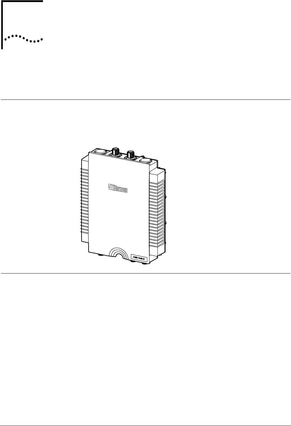
Product Front View
Figure 1 shows the front view of WA6011/6012. The device is waterproofed
by using completely wipe out encapsulation.
Figure 1 WA6011/6012 Front View
Product Features
• Compliant with IEEE802.11a/b/g
• Supports PTP (point to point), PMP (point to multi-points) wireless
bridge mode
• The assembled antenna is facility for user to use the outdoor antenna
easily
• Automatically select data transfer rate
• Supports a router mode
• Supports 802.1x to provide high data security
• Supports DHCP server
• Supports RADIUS Client
• Supports 802.1x
1
4 Chapter 1 Overview
User Guide WA3001-S Access Point
• Supports PPPoE pass-through
• Supports NAT
• Supports broadcast threshold
• Supports 64/128-bit WEP encapsulation
• Supports remote firmware management
• Provides load-balancing control based on the volume of traffic and the
number of accesses
• Supports MAC address filter configuration
• Provides WEB, SNMP, and CLI based management
Note: In this guide, the description about WA6011 is the same
as WA6012 if there is no specific illustration.
Network Topology
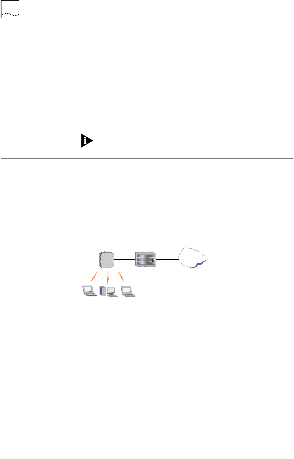
AP Mode
WA6011/6012 can provide wireless access (AP mode). AP is used to
establish connection between wireless network and wired network, while its
wireless network can support up to hundred users within hundred meters.
Figure 2 shows an example of WA6012 in AP mode. AP connects to WAN
through ADSL, while it is connected with wireless users through its wireless
network card.
Figure 2 Network Topology in AP Mode
AN-2000 IB Rev.2.0
WA6012
Internet
IP-DSLAM
RJ11
WLAN
Point To Point Mode (P2P)
WA6011/6012 can work in P2P mode, connection between wireless network
and wired network through two APs realizes resource sharing, as well as
network extension. Figure 3 shows that the wired LAN of AP-2 accesses
network resource in bridge mode connected with AP-1, meanwhile AP can
have wireless access.
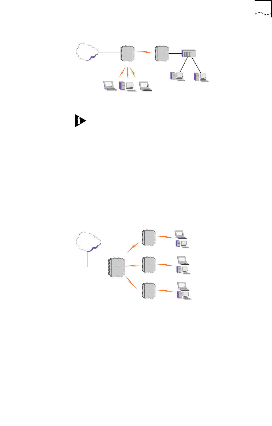
Chapter 1 Overview 5
WA3001-S Access Point User Guide
Figure 3 Network Topology in P2P Mode
...
WA6011AP-1 WA6011 AP-2
WLAN
Internet RJ45
Ethernet
LAN
HUB
Note: WA6011/6012 can configure two network cards
simultaneously. One is configured in AP mode for WLAN, the other one is
configured in P2P or P2MP mode for wireless bridging among two or more.
To avoid radio interference, configuring two network cards on different
working channels is recommended.
Point To Multi-Point Mode (P2MP)
P2MP wireless network bridging is able to connect several individual remote
networks together. Its network topology is more complicated than P2P. In
P2MP mode, radio signal is sent from one network as the center, other
receiving points receive the signals. WA6011/6012 supports up to six remote
APs’ access.
Figure 4 WA6011 Network Topology in P2MP Mode
WA6011 AP-1
WLAN
WLAN
WLAN
Internet
WA6011 AP-2
WA6011 AP-3
WA6011 AP-4

WA3001-S Access Point User Guide
2 Hardware Installation
Package Contents
Before the installation, check the following accessories in the box:
• WA6011 (AC Power Supply)
- One WA6011
- 50m Ethernet cable
- 35m AC power cable
- One Console cable with RS232 Interface (Option)
- One Installation Rack
- Four screws
- Four sleeves
- One User Guide (this one)
- One guarantee card
• WA6011 (DC Power Supply)
- One WA6011
- One PoE module with power cable
- 50m Ethernet cable
- One Console cable with RS232 Interface (Option)
- One Installation Rack
- Four screws
- Four sleeves
- One User Guide (this one)
- One guarantee card
• WA6012
- - One WA6012
- - 50m ADSL cable
- - 35m power cable
- - One Console cable with RS232 Interface (Option)
- - One Installation Rack
- - Four screws
- - Four sleeves
- - One User Guide (this one)
- - One guarantee card
2
8 Chapter 2 Hardware Installation
User Guide WA3001-S Access Point
Note: 1. If you find anything missing or if the documentation set is
incomplete, contact your local dealer immediately.
2. The product is only for professional installation.
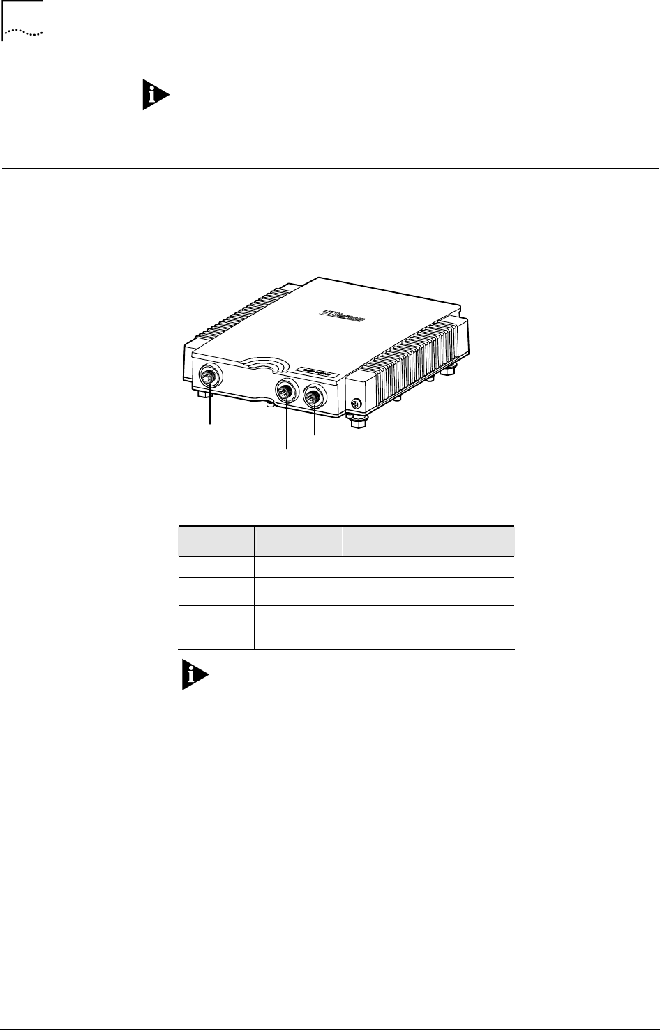
Interface Description
WA6011/6012 side panel (I) is shown in Figure 5. Table 1 describes the
interfaces on the side panel (I).
Figure 5 WA6011/6012 Side View (I)
220V DATA
CONSOLE
Table 1 Interface Description on Side Panel (I)
Interface Color Description
220V Red AC Power Connection Adapter
CONSOLE Green RS232 port provides CLI
configuration interface
DATA
WA6011: Blue
WA6012: Yellow
Data Interface:
WA6011: Ethernet port;
WA6012: ADSL port
Note: WA6011 supports PoE
(
Power Over Ethernet
)
mode.
Use an Ethernet cable to connect AP’s Data interface with the DC power
output port in the DC power supply module to implement data transmission
and DC power supply.
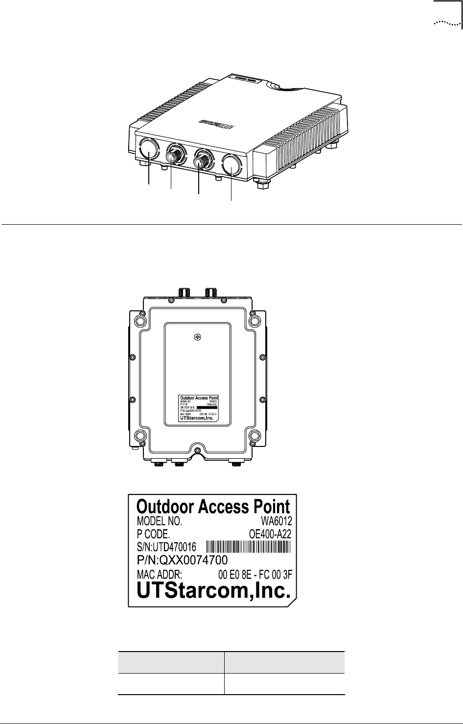
Figure 6 shows the side panel (II) of WA6011/6012. WA6011 provides four
antenna jacks marked with number 1 to 4 from left to right. Two wireless
network cards can be installed. Jack 2 & 3 are used if only one network card
installed; If two network cards are installed at the same time, jack 1 & 2 are
used for one card, jack 3 & 4 are used for the other card.
Chapter 2 Hardware Installation 9
WA3001-S Access Point User Guide
Figure 6 WA6011/6012 Side Panel (II)
1234
Product Label Description
The label on the bottom of WA6011/6012 marks the product model and code.
Figure 7 WA6012 Bottom View
Table 2 Label Description
Name Description
Outdoor Access Point Outdoor Access Point

10 Chapter 2 Hardware Installation
User Guide WA3001-S Access Point
Name Description
MODEL NO WA6012
P CODE
Product Code:
O: outdoor
E: Ethernet port
A: ADSL port for WA6012
400:400mw power
A: AC power supply
D: PoE
2: Support b/g mode
3: Supports a/b/g mode. A
supplementary digit represents
two network cards installed.
S/N Serial number
MAC ADDR Device MAC address
Cable Connection
WA6011/6012 are outdoor AP, its rack installation, please refer to
WA6011/6012 Outdoor AP Installation Guide. The cable connection will
be described in this section.
WA6011 in AP mode:
• AC power supply
1 Connect the 220V AC power adapter to the AC power supply
2 Connect the DATA interface in AP to the Internet (usually is a port of an
Ethernet switch) through a data cable
3 Configure the wireless network card for wireless users access
• PoE power supply
1 Connect the 220V power connection socket on PoE module to the AC
power supply through a power cable
2 Connect the Input jack in PoE module to the internet (usually is a port of
an Ethernet switch) through an Ethernet cable
3 Connect the DATA interface in AP to the Output interface in PoE
module through a data cable, the cable provides data transmission and
DC power
4 Configure the wireless network card for wireless users access
WA6012 in AP mode:
1 Connect the 220V AC power adapter to the AC power supply
2 Connect the DATA (ADSL) interface in AP to the internet through a data
cable
3 Configure the wireless network card for wireless users access

Chapter 2 Hardware Installation 11
WA3001-S Access Point User Guide

WA3001-S Access Point User Guide
3 Web-based Configuration
Introduction
There are two working modes available in WA6011: Route and Bridge mode.
The default is bridge mode.
WA6011 default settings:
• Working mode is Bridge mode
• IP Address of the LAN interface is 172.18.37.1. Mask is 255.255.255.0.
• ESSID of wireless interface is set to “UT”. Wireless channel is set to “1”
• When the AP is in route mode, IP Address of the WAN interface is
192.168.1.1. Mask is 255.255.255.0.
If security setting is not requested, only ESSID setting in the wireless
network card of user’s terminal is configured to be same as the one in the
AP, then AP can work properly with the card after power is supplied
(WA6012 needs to set VPI/VCI)
Login AP
Access the AP through LAN port or the uplink port:
• After the configuration of AP and PC wireless network card is completed,
the user can access AP wirelessly. (AP works in Bridge or Router mode)
- Install a wireless network card in a PC, set its IP Address the same
as the AP’s and LAN port’s, e.g. 172.18.37.10, Mask:
2555.2555.255.0, set the ESSID the same as the AP’s, check the
status of the wireless network card, make sure it connects to the AP.
Logon to the WA6011/6012 through the web browser.
• Access AP through the uplink ports
- In Bridge mode, the IP addresses of the PC and the AP LAN
interface should be set the same, e.g. 172.18.37.10. Use the web
browser to logon.
Note: To access AP through the Ethernet port on DSLAM
because the uplink of WA6012 is ADSL (RJ11)
- In Route mode, the IP addresses of the PC and the AP’s WAN
interface should be set the same, e.g. 192.168.1.10. Set the Mask
to 255.255.255.0. Use the web browser to logon.
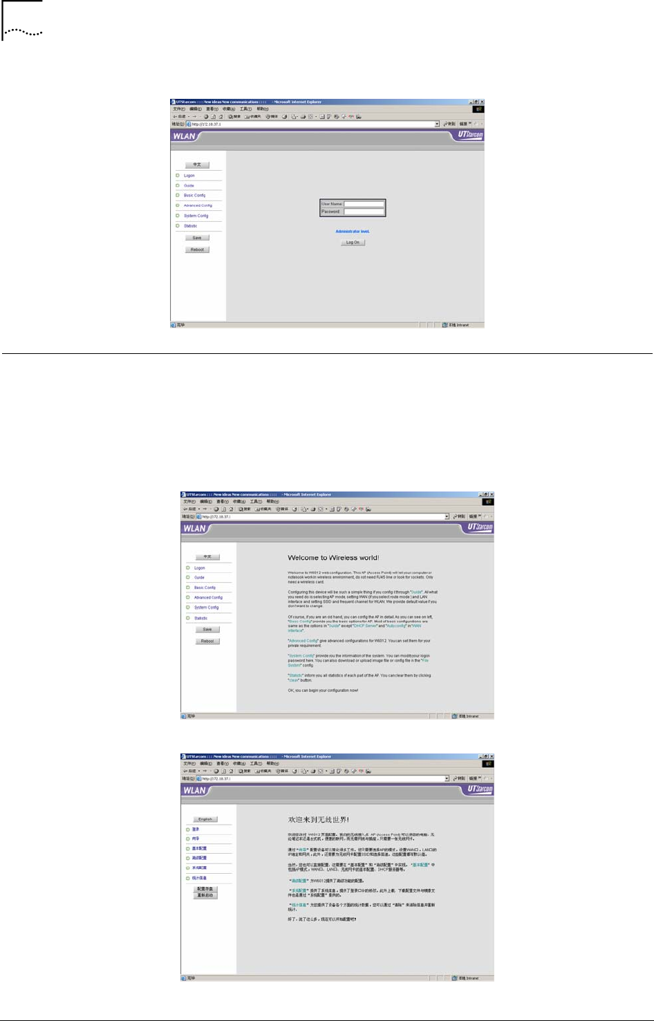
The Logon Interface is displayed in Figure 8. The user name for
administrator is “admin”, and password is “admin”. The user name for guest
(read only) is “guest”, the password is “guest”. The administrator has right to
set all configurations for the AP, but guests can read the AP status and
statistic information only
3
14 Chapter 3 Web-based Configuration Introduction
User Guide WA3001-S Access Point
Figure 8 Logon Window
Web Configuration User Interface
WA6011 web user interface (UI) is shown in Figure 9. The left panel lists all
configuration options, save and reboot buttons. Click on the <中文> button to
switch the UI to Chinese mode, see Figure 10
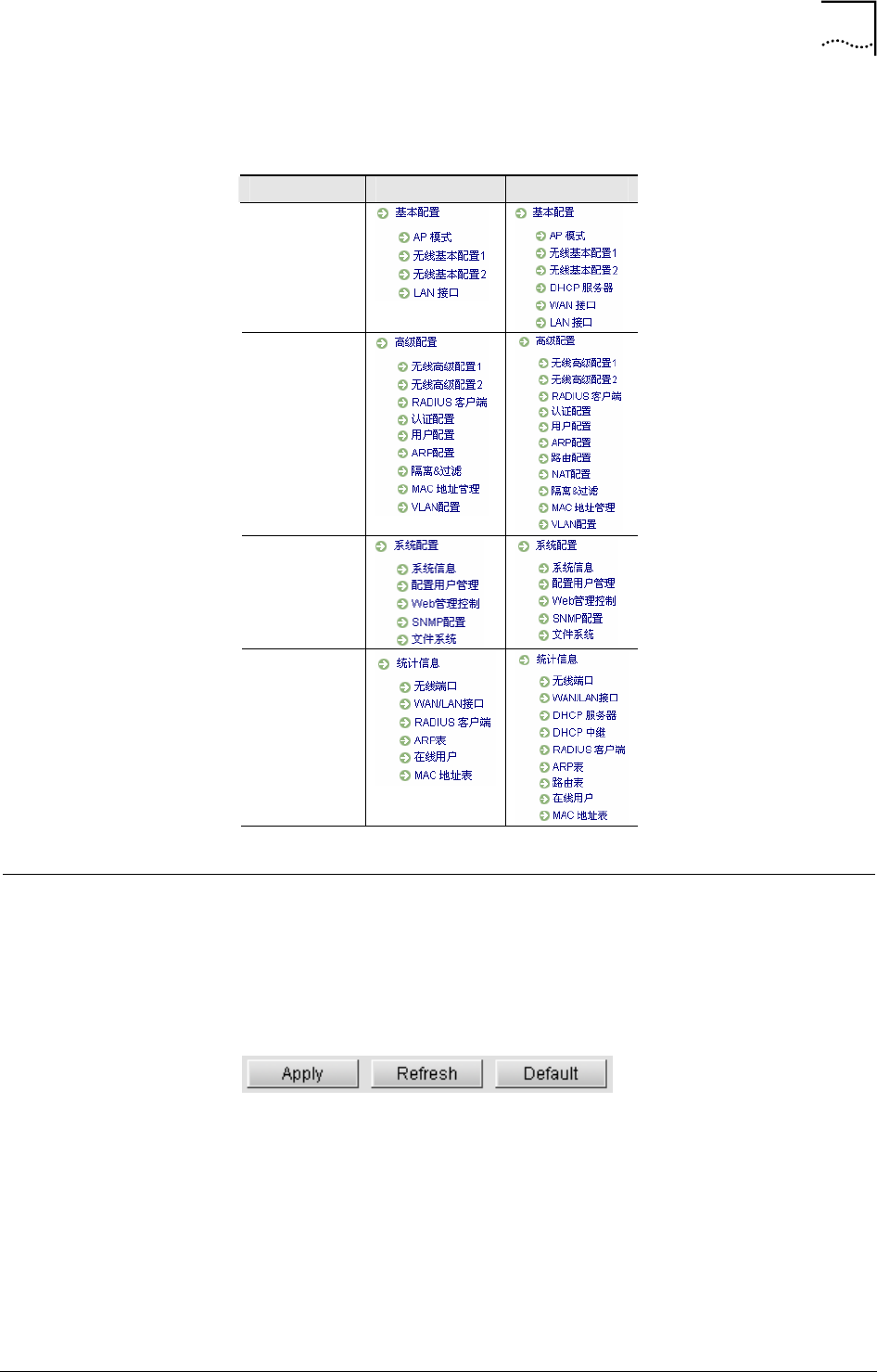
Table 3 lists all configuration options in Bridge and Route modes (WA6011)
Figure 9 Web Configuration UI (English)
Figure 10 Web Configuration UI (Chinese)
Chapter 3 Web-based Configuration Introduction 15
WA3001-S Access Point User Guide
Table 3 Configuration Description Table (WA6011)
Menu Bridge Mode Router Mode
Basic Config
Advanced Config
System Config
Statistic
Button Description
In the main configuration options window, there are two more buttons,
“Save” and “Reboot” available in the left panel of the logon screen, click
<Reboot> to re-start the AP.
The buttons shown in Figure 11 will appear during the configuration.
Figure 11 Buttons
• <Apply>: Press to apply a configuration changes. Some configurations
are applied only after saving and rebooting the AP. The corresponding
prompt window will pop up.
• <Refresh>: Press <Refresh> to refresh the interface.
• <Default>: Press <Default> to restore the default parameters.
For some parameter’s configuration, e.g. ESSID, click <Apply>, the system
will prompt that the configuration will be effective after save and reboot the
AP, see Figure 12

16 Chapter 3 Web-based Configuration Introduction
User Guide WA3001-S Access Point
Figure 12 AP Reboot Prompt Window
Note: Click <Save> to save the configuration changes even if it
has been applied by clicking <Apply>
WA3001-S Access Point User Guide
4 Web-based Configuration
This chapter will introduce all Web configurations in Route mode. The Web-
based configuration in Bridge mode will not be described here because they
are included in the configurations in Route mode.
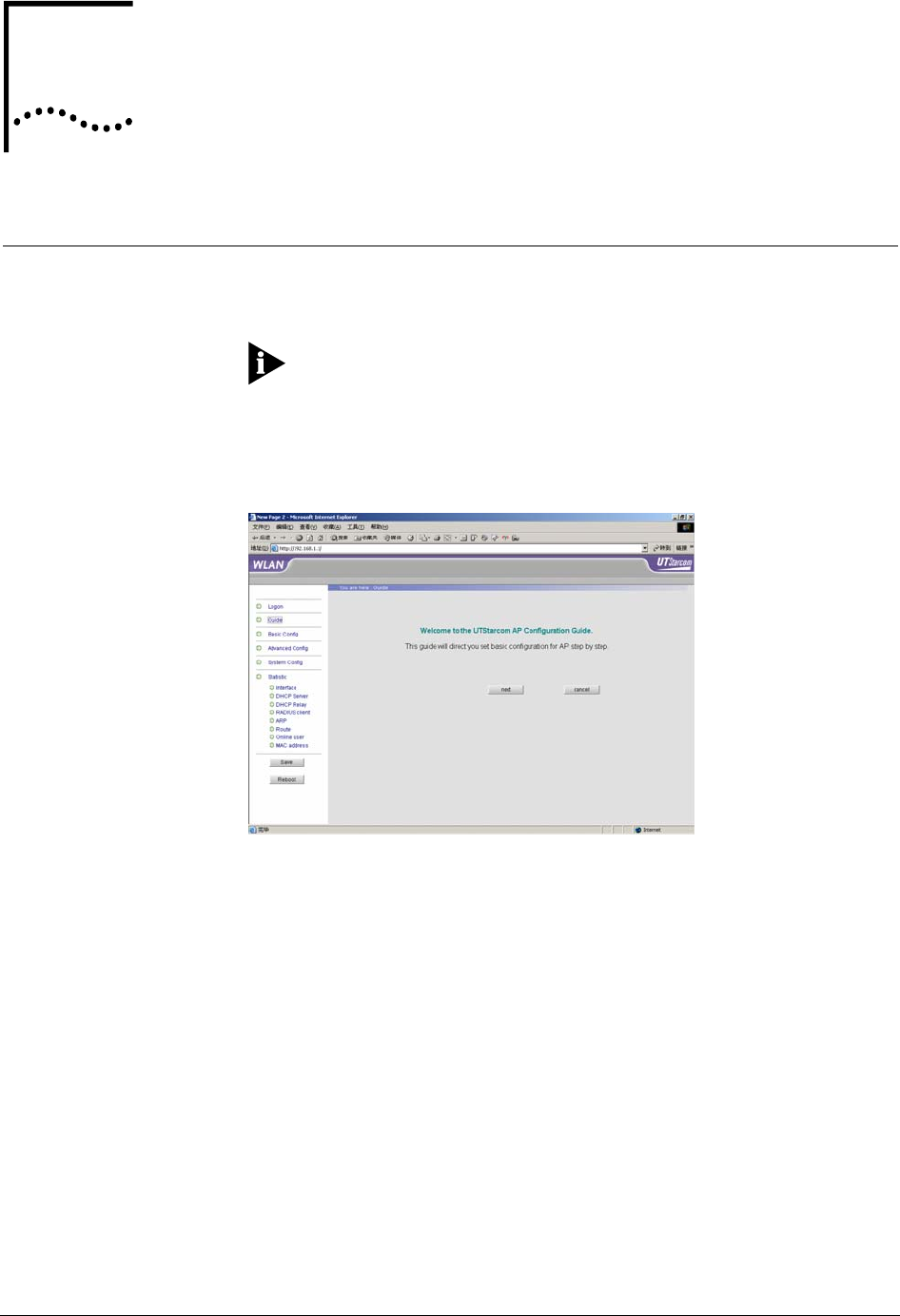
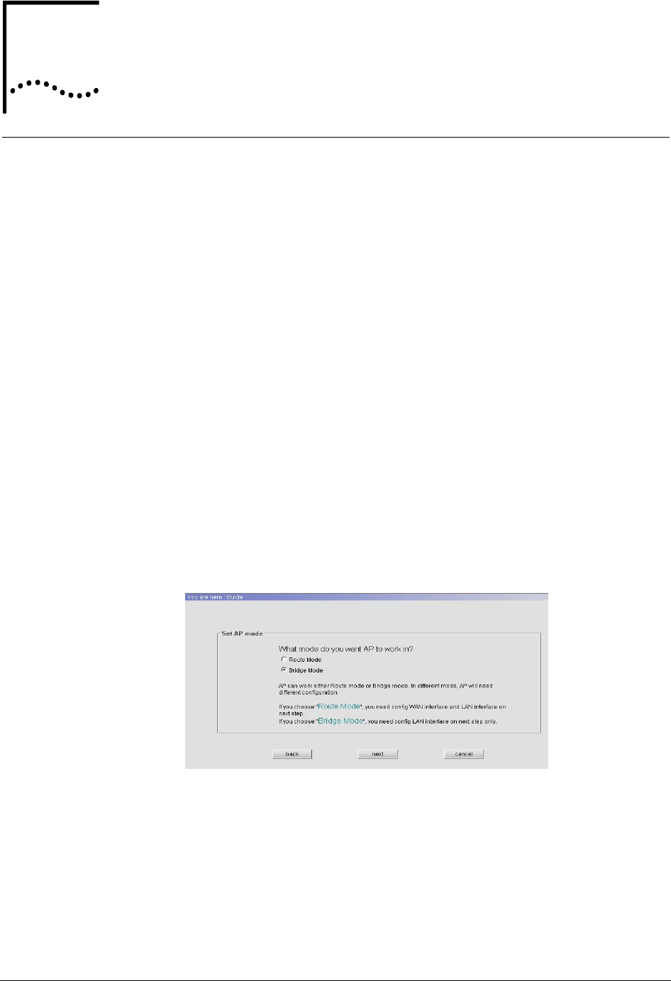
Guide Configuration
“Guide” provides users the ability to configure the AP in Route/Bridge mode
according to the instructions in the Web interface.
Note: User can configure more functions via “Basic config” and
“Advanced config”
Refer to Figure 13, click “Guide” on the left panel of the Logon interface.
Figure 13 Guide Configuration
Entering the Guide configuration window, as shown in Figure 14
4
18 Chapter 4 Web-based Configuration
User Guide WA3001-S Access Point
Figure 14 AP Mode Setting
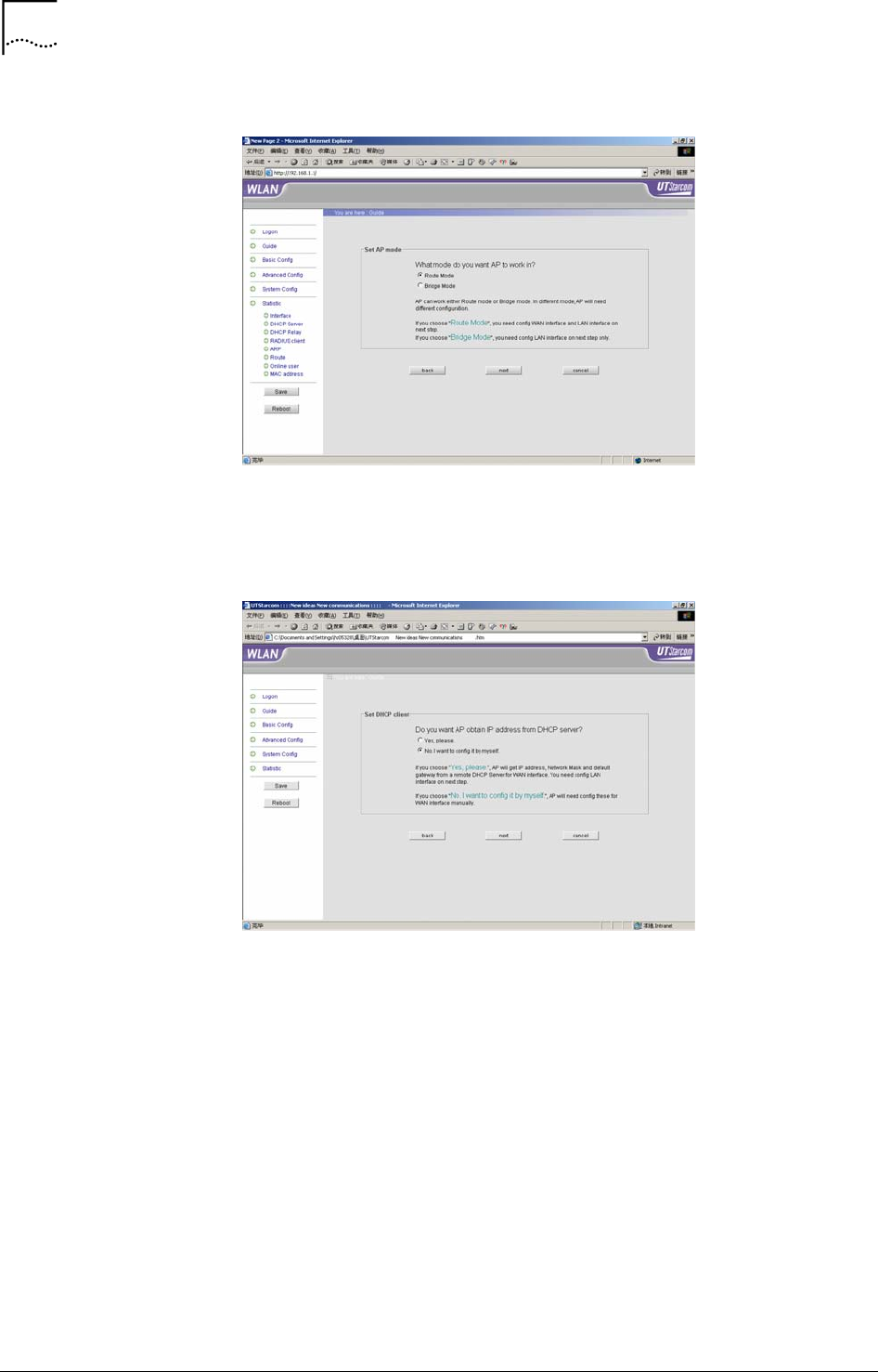
• Configuration in Route Mode
Select “Route Mode” in Figure 14, click “next” to go to the route mode
configuration screen as shown in Figure 15.
Figure 15 DHCP Configuration
If you want to obtain the IP address for the WAN port from the DHCP server,
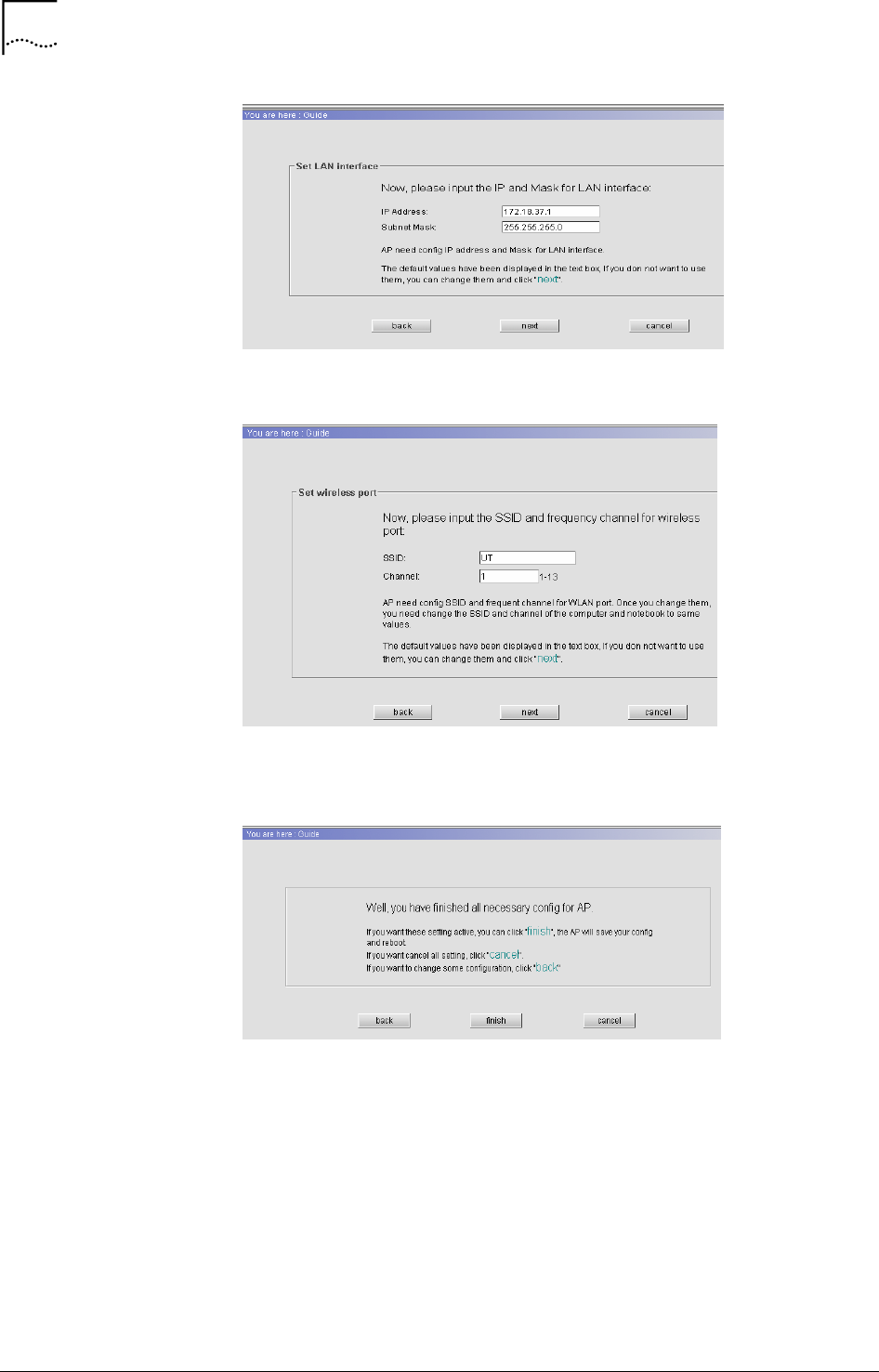
select “Yes, please”, then click <next> to go to the LAN port configuration
window, as shown in Figure 16
Chapter 4 Web-based Configuration 19
WA3001-S Access Point User Guide
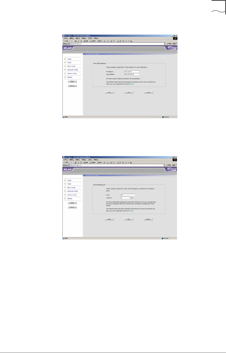
Figure 16 LAN Port Configuration
The LAN port configuration window displays the default IP Address and
Mask. The IP address is able to enter a new one, then click <next> to go to
the wireless port configuration, as shown in Figure 17
Figure 17 Wireless Port Configuration
The default SSID is “UT”, and the Channel is “1”. The value of SSID and
channel are changeable. User can access the AP only when the ESSID
setting in the wireless network card of user’s terminal is configured to be
same as the one in the AP. Click <next> to go to the completed configuration
window shown in Figure 18. Click <finish>, the AP will save the configuration
and restart automatically.
20 Chapter 4 Web-based Configuration
User Guide WA3001-S Access Point
Figure 18 Configuration Completed
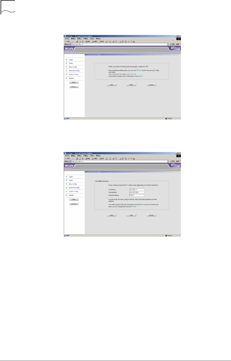
To obtain the IP Address for the WAN port by manually, select “No, I want
config it by myself” as shown in Figure 15, then click <next>, see Figure 19.
Figure 19 WAN Port Configuration
The AP default IP address for the WAN port is 192.168.1.1, Mask is
255.255.255.0, and the default Gateway is 0.0.0.0.
Click <next>, the system prompts the LAN port and Wireless port
configuration. Finally, click <finish>, the AP will save the configuration
changes and restart automatically.
• Configuration in Bridge Mode
Select “Bridge Mode” in Figure 14, the system will guide user how to
configure the IP address for LAN port, and the SSID and Channel for
wireless port. The details will not be described here because they are
included in the configurations in Route mode. Please refer to the
configuration steps in Router mode.
Chapter 4 Web-based Configuration 21
WA3001-S Access Point User Guide
Basic Configuration
This section introduces each item of the basic configuration of WA6011
including WAN, LAN and wireless port configuration.
Click “Basic Config” on left panel of the Logon interface, the basic
configuration items of the AP will be displayed. The following sections will
describe each item.
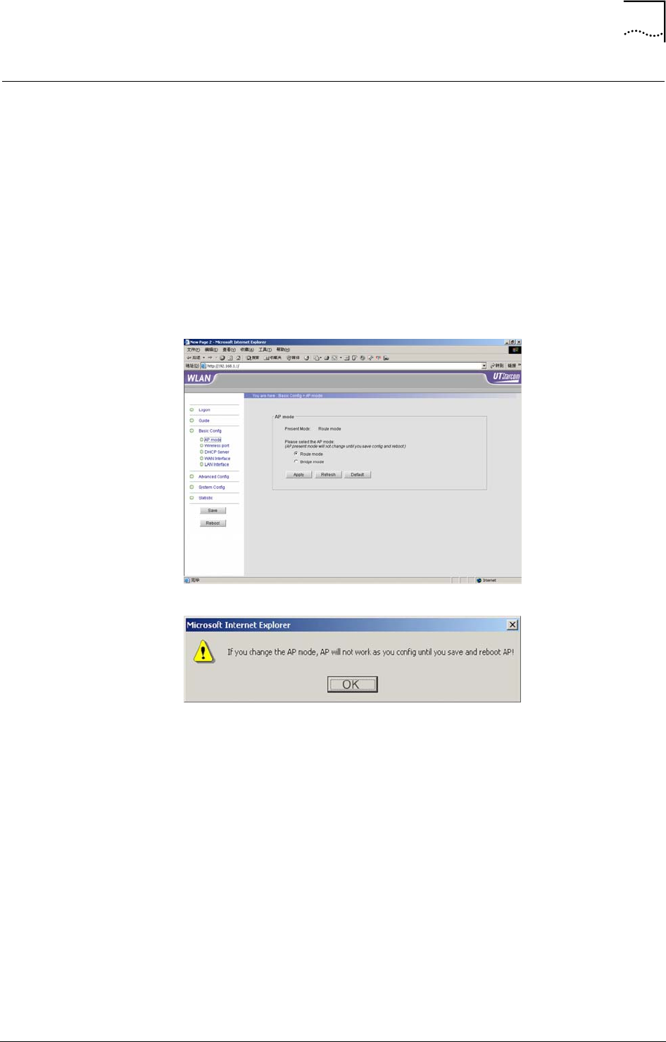
AP Mode Configuration
Click “AP mode” on left panel of the Logon interface, see Figure 20, Route
Mode is the default. Click <Apply> after configuration completed. See Figure
21, the popup dialogue box prompts that the configuration will not work until
it’s saved, then reboot the AP.
Figure 20 AP Mode Configuration
Figure 21 Prompt Window after Apply AP Mode Changes
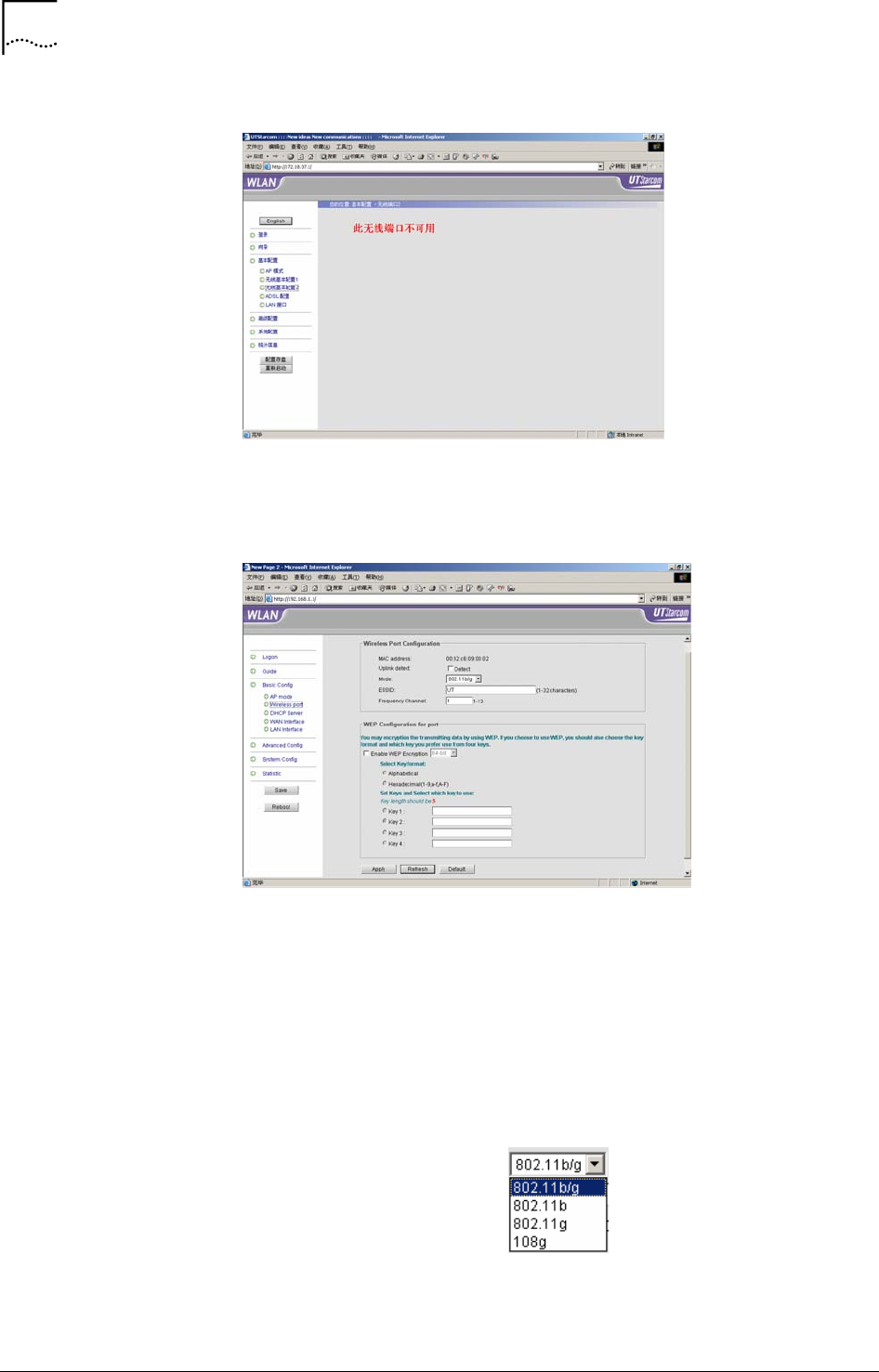
Wireless Port1/Wireless Port 2 Configuration
Two wireless network cards can be installed in WA6011. Their
corresponding configuration ports are wireless port 1 and wireless port 2.
Figure 22 displays the port configuration without wireless network card
plugged.
22 Chapter 4 Web-based Configuration
User Guide WA3001-S Access Point
Figure 22 Wireless Port Configuration (without Wireless Network Card)
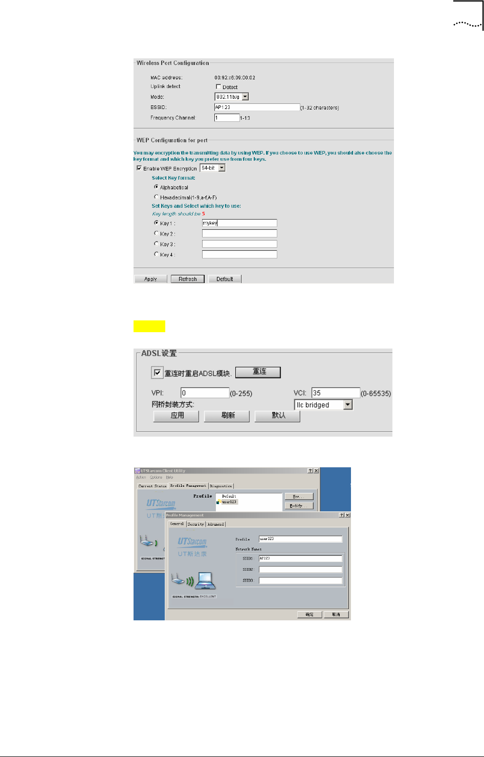
Click “Wireless port 1” to go to the Wireless Port Configuration section on
the top of the window as shown in Figure 23.
Figure 23 Wireless Port Configuration
• Wireless Port Configuration
- Uplink detect: If the “Detect” check box is selected, after click
<Apply>, the AP will automatically disconnect from the wireless
LAN when the uplink has been lost or does not work properly.
- Mode: WA6011 complies with the 802.11b/g which is the default
working mode. Data transfer speed in 108g mode is 108Mbps. Click
<Apply>, the system will prompt to save the configuration and
reboot the AP.
Chapter 4 Web-based Configuration 23
WA3001-S Access Point User Guide
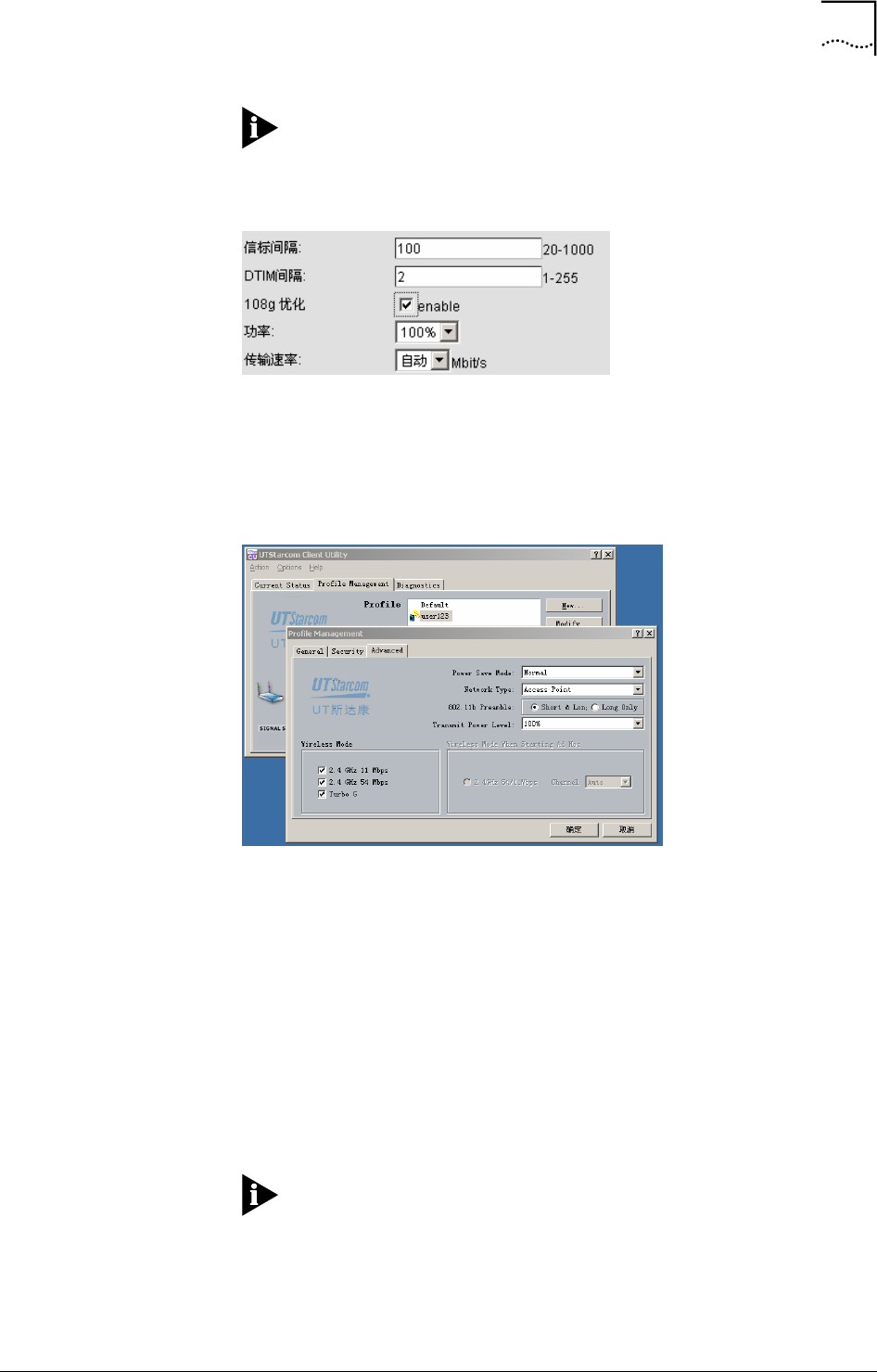
Note: When the 108g mode is selected, the “108g optimization”
parameter option in “Advance Config/Wireless Port Config” has to be
activated. See Figure 24
Figure 24 108g Optimisation Parameter Configuration
In addition, the wireless network card should support 108g to implement
108g mode, e.g. UTStarcom WNIC2010 Wireless Network Card. See Figure
25, select the “Turbo G” function in the “Advance” option menu in WNIC2010
Utility Settings.
Figure 25 Set WNIC2010 to Enable Turbo G Mode
- ESSID: Each AP can be set with a specific ESSID (or they can be
set the same), also each wireless card can be set with a specific
ESSID. The AP only accepts wireless access when the ESSID of
the wireless card matches the AP’s ESSID. Specific ESSIDs can be
used for grouping users to avoid security and access problems
arising from random roaming. the default ESSID of WA6011 is “UT”,
but other ESSIDs are accepted between 1-32 characters. Click
<Apply>, the system will prompt to save the configuration and
reboot the AP.
- Frequency Channel: The Channel can be set in the range of 1-13.
The default is 1.
Note: The Frequency Channel is fixed to 6 by the system when
the Mode is “Dynamic G” or 108g.
• WEP Configuration
24 Chapter 4 Web-based Configuration
User Guide WA3001-S Access Point
WEP encryption uses a static secret key, each WLAN terminal uses the
same key to access the wireless network. WA6011 supports 64-bit or 128-
bit static WEP encryption, to prevent illegal access of data.
- Enable WEP encryption: select either 64-bit or 128-bit encryption
mode
- Select Key format: Select either Alphabetical or Hexadecimal.
Description:
• 64-bit WEP keys (password) can use any 5 alphanumeric characters
between “a-z”, “A-Z” and “0-9” or 10 hexadecimal digits between (0-9, A-
F). For example, a 5-character password string could be “MyKey”. Or
input 10 digits like “11AA22BB33” for a Hexadecimal key.
• 128-bit WEP keys (passwords) can use any 13 alphanumeric characters
between “a-z”, “A-Z” and “0-9”, or 26 hexadecimal digits between (0-9,
A-F). For example, a 13-character password string could be:
utstarcomKey1. Or input 26 digits: “00112233445566778899AABBCC”
for a Hexadecimal key.
Switch the configuration to wireless port advance configuration by clicking
the “Advanced Config” link on the bottom-right screen.
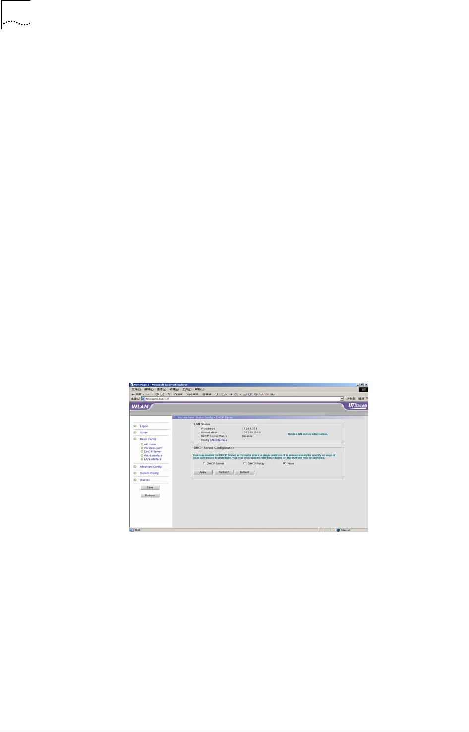
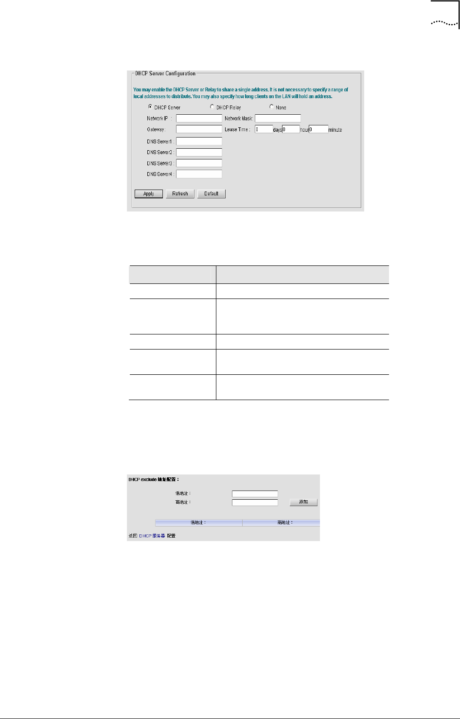
DHCP Server Configuration
Click “DHCP Server”, see Figure 26, “LAN Status” shows the AP’s current
LAN configuration. The default DHCP Server Status is “Disable”
Figure 26 DHCP Server
• DHCP Server
Select “DHCP Server”, the configuration window will appear as shown in
Figure 27.
Chapter 4 Web-based Configuration 25
WA3001-S Access Point User Guide
Figure 27 DHCP Server Configuration
Table 4 describes the configuration parameters of DHCP server
Table 4 DHCP Server Parameter Description
Parameters Descriptions
Network IP IP address of DHCP address pool
Network Mask The network IP address pool plus a
Subnet Mask to define a DHCP server
address pool.
Lease Time IP address lease time
Gateway Gateway address, i.e. IP address of LAN
interface.
DNS Server1-4 DNS servers, up to 4 servers can be
configured.
Configure those IP address which are not allowed to assign to users by click
“DHCP server Config” on the bottom screen. See Figure 28, set a specific IP
address or a subnet.
Figure 28 DHCP exclude Address Configuration
- The first IP address (byte) of a specific IP address or an IP subnet
- The last IP address (byte) of an IP subnet
• DHCP Relay
Select “DHCP Relay”, the configuration details are shown in Figure 29.
26 Chapter 4 Web-based Configuration
User Guide WA3001-S Access Point
Figure 29 DHCP Relay Configuration
Three IP addresses of trusted DHCP server can be set here. The AP will
obtain LAN’s IP address, Subnet mask, Gateway, and DNS server from the
DHCP server configured here.
DHCP exclude IP address can be configured in DHCP Relay mode.
• None
Select “None” to disable the DHCP server
WAN Interface Configuration (WA6011)
Click “WAN Interface”, see Figure 30, “WAN Interface Status” displays the
current WAN port status.
Figure 30 WAN Interface Configuration (WA6011)
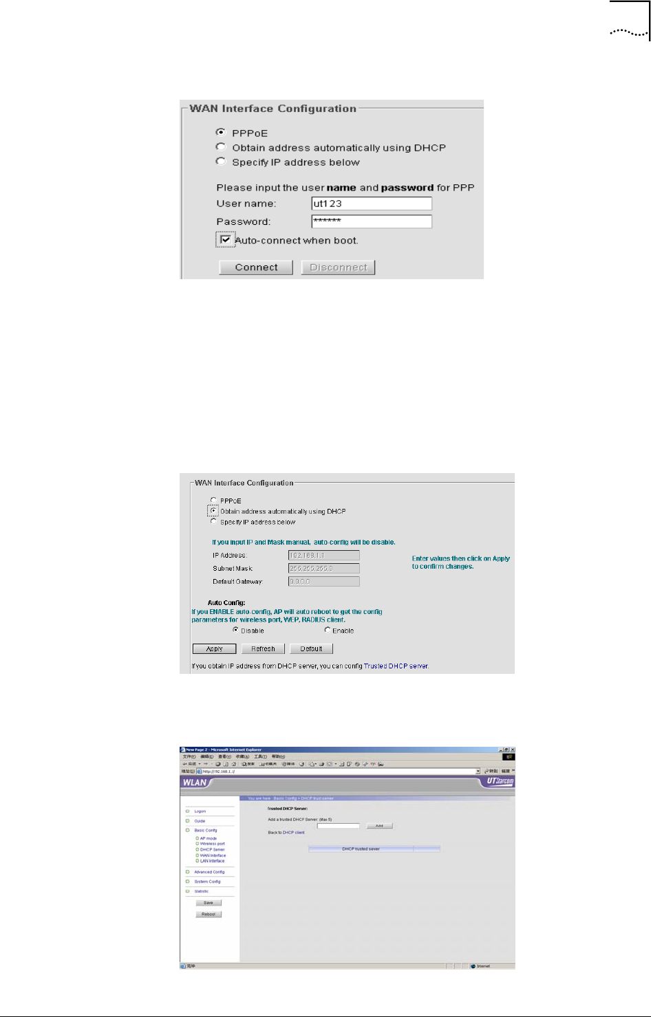
• PPPoE:WA6011 can obtain the WAN IP address via PPPoE dialup,
see Figure 31.
Chapter 4 Web-based Configuration 27
WA3001-S Access Point User Guide
Figure 31 PPPoE Configuration
Enter user name and password provided by the service provider. Click
<Connect> to dial up, when the dialup is successful, the <Disconnect>
button will be activated. Select “Auto-connect when boot” to automatically
connect after the AP is rebooted.
• Obtain address automatically using DHCP
Click “Obtain address automatically using DHCP”, see Figure 32. The WAN
IP address is automatically assigned to AP through DHCP server
Figure 32 Obtain Address Automatically Using DHCP
Click “DHCP Trusted Server”, see Figure 33.
Figure 33 Trusted DHCP Server Configuration
28 Chapter 4 Web-based Configuration
User Guide WA3001-S Access Point
After the configuration of Trusted DHCP Server IP address, the AP will
obtain the WAN IP address from the configured Trusted DHCP Server only.
Click “Back to DHCP client” will return back to WAN interface configuration
window.
• Specify IP address:
Click “Specify IP address”, user can configure the WAN IP address manually
as shown in Figure 34. Click <Apply> to take the configuration effective.
Figure 34 Specify IP Address Manually
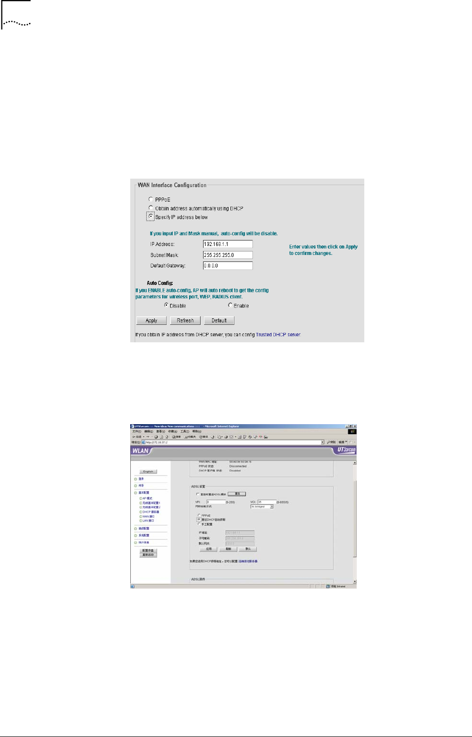
WAN Interface Configuration (WA6012)
WA6012 WAN interface configuration window is shown in Figure 35. It
contains “WAN Interface Status”, “ADSL Set” and “ADSL Firmware” options.
Figure 35 WAN Interface Configuration (WA6012)
• ADSL Configuration
- Reboot ADSL after Reconnection: ADSL module will get reboot
when ADSL re-connects every time
- VPI/VCI: VPI/VCI setting is same as what DSLAM setting is
- Network bridge WEP: llc bridged/vcmux bridged, the default is “llc
bridged”
Chapter 4 Web-based Configuration 29
WA3001-S Access Point User Guide
For the detailed configuration of “PPPoE”, “Obtain address automatically
using DHCP” and “Specify IP address”, please refer to “WAN Interface
Configuration (WA6011)” section.
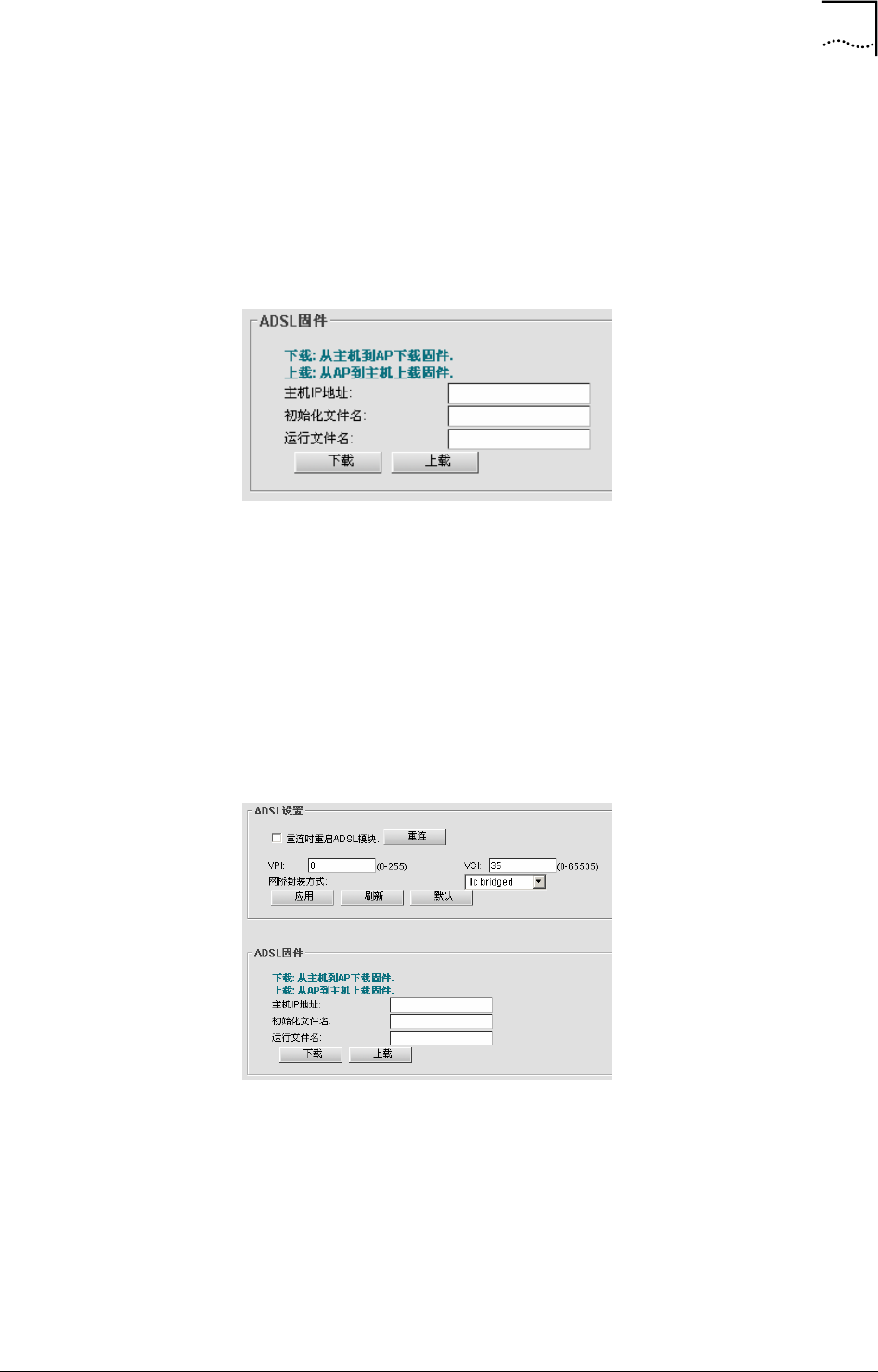
• Figure 36 shows the ADSL firmware configuration
ADSL module upgrade or ADSL image files backup can be done through
“ADSL Firmware”.
Figure 36 ADSL Firmware Configuration
- Host IP address: Access AP host IP address
- Initialization File Name/Execution File Name: AP image files
Execute TFTP program and configure file path, click <Download> to start
ADSL module upgrade, or click <Upload> to backup ADSL image file.
ADSL Configuration (WA6012 in Bridge Mode)
WA6012 ADSL configuration in Bridge mode contains “ADSL config” and
“ADSL firmware” options, as shown in Figure 37
Figure 37 ADSL Configuration
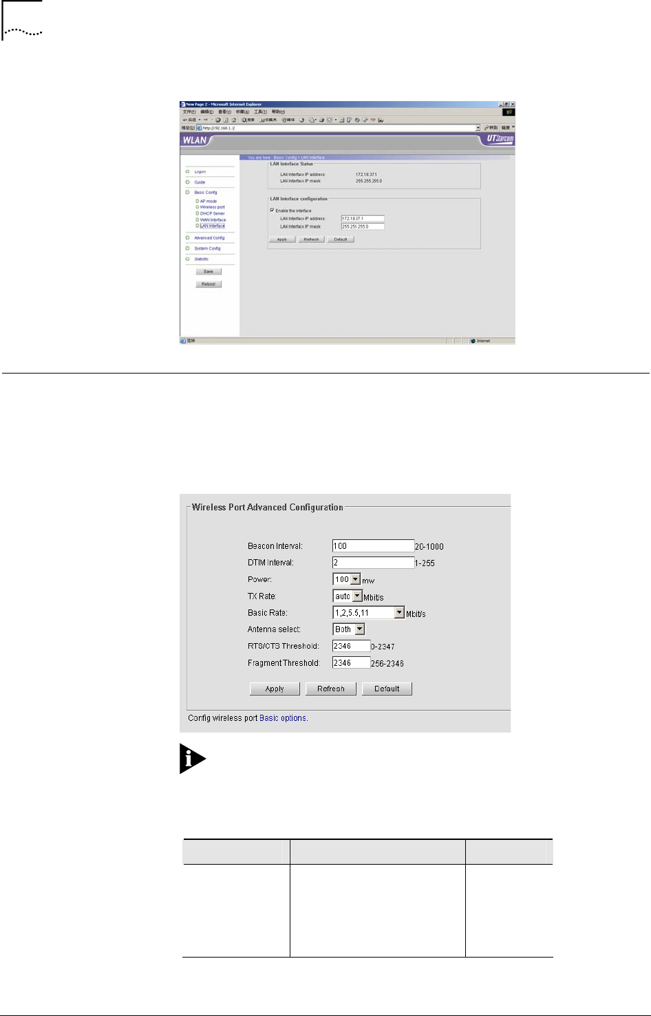
LAN Interface Configuration
Click “LAN Interface”, the current LAN IP address and MAC address are
shown in Figure 38. Click <Apply> to take the IP address effective.
30 Chapter 4 Web-based Configuration
User Guide WA3001-S Access Point
Figure 38 LAN Interface Configuration
Advanced Configuration
Wireless Port1 Configuration/Wireless Port2 Configuration
Click “Advanced Config/Wireless Port 1 Advanced Configuration”, see
Figure 39.
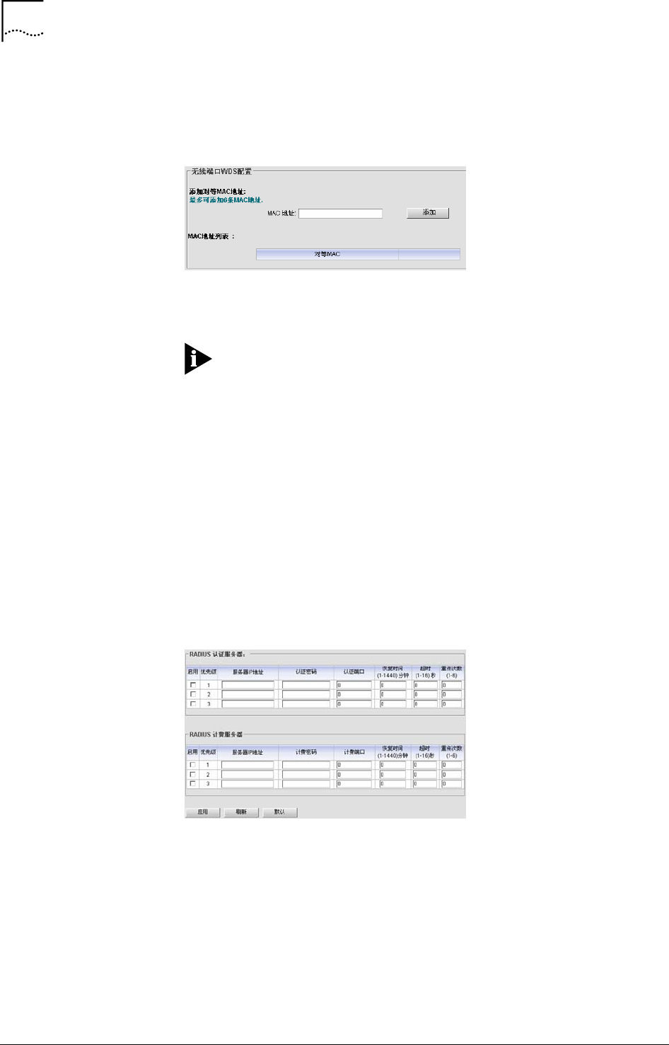
Figure 39 Wireless Port Advanced Configuration
Note: Same as the wireless basic configuration, the interface will
display “the wireless port cannot be used” when the wireless network card is
unplugged.
Table 5 Wireless Port Parameters Description
Parameters Specifications Default
Beacon Interval
Interval between Beacon
packets, the Beacon packet
contains network card
information, duration of
broadcast to the wireless
network.
100(ms)

Chapter 4 Web-based Configuration 31
WA3001-S Access Point User Guide
Parameters Specifications Default
DTIM Interval Interval between Delivery
Traffic Indication Messages.
2 x Actual
beacon
interval
Power
Transmitting power of the AP
wireless port. Possible
values: 12%,25%,50%,
100%.
100%
(400mw)
Tx Rate
Transmission rate. The
range of selectable values is
decided based on the
wireless mode set in the
basic configuration. If Auto is
chosen, the network card will
select current the optimum
rate.
auto
Basic Rate The network card is
restricted to operating at a
selected Tx rate at least.
1,2,5.5,11Mb
it/s
Antenna Possible values: Both, Ant A,
Ant B Both
RTS/CTS
Threshold
WLAN is using the
mechanism of Request To
Send/Clear To Send.
RTS/CTS threshold can be
set, RTS/CTS is used when
the data packet size exceeds
the threshold. Choose a
setting within a range of 0 –
2347. It is advisable not to
change this setting.
2346
Fragment
Threshold
Fragment threshold is used
to improve the efficiency in a
high volume wireless
network. Define the data
packet size limit here. Any
packet greater than this
value will be fragmented.
Choose a setting within a
range of 256 – 2346 bytes. It
is advisable not to change
this setting.
2346
WA6011 is able to work in multiple modes:
• AP mode: The AP is connected to the WAN through its uplink port and
provides access to the wireless network through its wireless ports. In
this way, the AP implements a combination of a wireless network with
the WAN.
• Repeater mode: The AP is implemented as a signal relay that enhances
signal strength. In this way, it extends the coverage of the wireless
network. The central AP is connected to the WAN and the remote APs
are connected to the central AP in bridge mode.
32 Chapter 4 Web-based Configuration
User Guide WA3001-S Access Point
Select “Repeater Mode”, click <Apply>, the system will prompt to save the
configuration and reboot the AP. The WDS (Wireless Distribution System)
configuration window is shown in Figure 40.
Figure 40 WDS Configuration
Enter MAC address, click <Add>, and set the other party of AP in Repeater
mode, then configure its MAC address
Note: Implement the wireless bridge and AP coverage by setting
one AP’s wireless network card in AP mode, and the other in Repeater
mode.
• P2MP
Click “P2MP mode”. The configuration steps are similar to those in
“Repeater mode”. A central AP can connect to a maximum of 6 remote APs.
Add MAC addresses for each remote AP through the window as shown in
Figure 40. Configure each remote AP by setting the mode to “P2MP mode”,
and then add the MAC address for the central AP.
RADIUS Client Configuration
Click “Radius Client” to configure the authentication server and the
accounting server. See Figure 41 for the details.
Figure 41 Radius Client Configuration
• Figure 41 shows the RADIUS Client configuration user interface
• Priority Level (1-3): AP will select a RADIUS server with 1st priority. Click
“Apply” to enable the selected RADIUS server.
• Authentication/Accounting Key: In the AP, the authentication/Accounting
key must be set to match the key in the RADIUS server.
• Authentication/Accounting port: Authentication/Accounting port number
Chapter 4 Web-based Configuration 33
WA3001-S Access Point User Guide
• Server dead time/Server timeout time/Server transmit times: If the
request sent to the Radius Server does not get a response within
Timeout value, the request is re-sent to the server until the number of
re-tries reaches the value set in the Transmit Times. If any re-try does
not get a response, then the AP considers that the Radius server failed.
It will wait a period of time as defined in the Dead Time. Then the AP will
re-send a request.
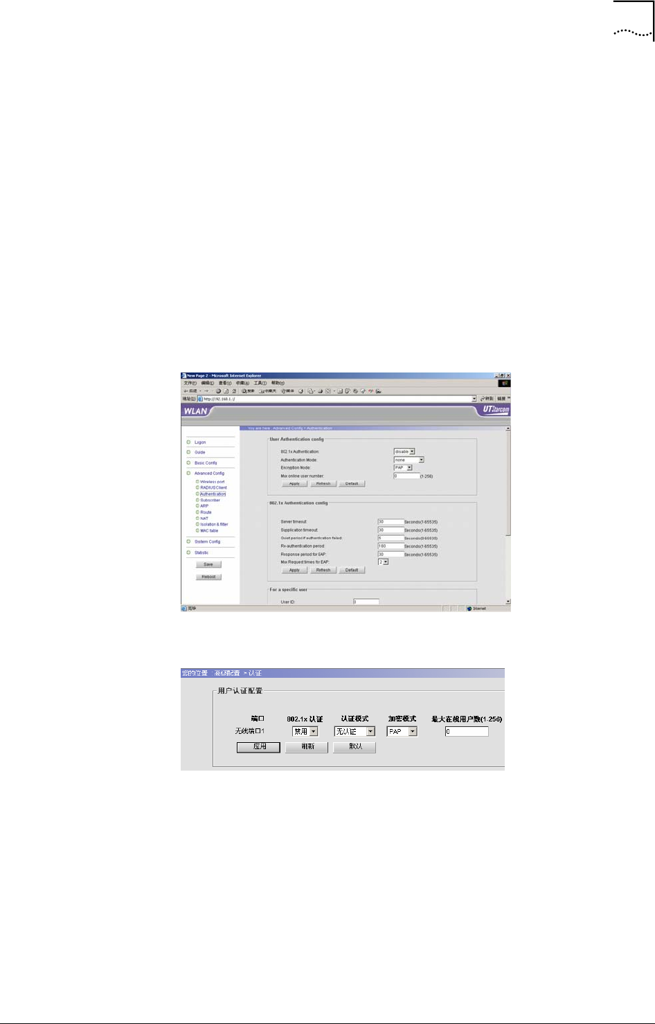
Authentication
WA6011 provides 802.1x authentication mode. The user can configure the
static or dynamic user information through “Subscriber”, and configure
802.1x authentication through “802.1x Authentication Config”.
Click “Advanced Config/Authentication”, see the configuration details in
Figure 42.
Figure 42 Authentication Configuration
• User Authentication Configuration user interface is shown in Figure 43
Figure 43 User Authentication Configuration
- Port: Display the installed wireless ports of Wireless port 1 and
Wireless port 2
- 802.1x Authentication: disable or enable, the default is “disable”
- Authentication Mode:
The available options are:
None
local-remote: WA6011 is the authentication point.
remote: RADIUS server authentication.
34 Chapter 4 Web-based Configuration
User Guide WA3001-S Access Point
local-remote: implement the remote authentication after the
local authentication is failed.
remote-local: implement the local authentication after the
remote authentication is failed.
- Encryption Mode: Choose either PAP or CHAP encryption mode.
- Max online user number: The range of the maximum number of
online users is 1-256.
• 802.1x Authentication Config: The configuration interface is shown in
Figure 44. Table 6 describes the configuration parameters’
specifications.
Figure 44 802.1x Authentication Configuration
Table 6 802.1x Authentication Config Parameter Specification
Parameter Specification Default
Server
timeout
Interval between retries of
sending a request frame
from AP to Server
(second). If within the
Timeout period the Server
doesn’t respond to the
AP’s request, the AP will
re-send the request frame.
Possible values: 1-65535
seconds.
30
Supplication
timeout
Interval between retries of
sending a request frame
from AP to Client
(second). If within the
Timeout period the Client
does not respond to the
AP’s request, the AP will
re-send the request frame.
Possible values: 1-65535
seconds.
30
Chapter 4 Web-based Configuration 35
WA3001-S Access Point User Guide
Parameter Specification Default
Quiet period if
authentication
failed
If the user name or
password failed because
of authentication, the AP
will not process the
authentication request
from the Client within
Quiet-period value.
Possible values: 1-65535
seconds.
5
Re-
authentication
period
Interval to re-authenticate
a client. Possible values:
1-65535 seconds. 180
Response
period for
EAP
Interval of AP sending
Request-challenge
request to the client under
EAP authentication (Re-
sending because the
Response-challenge was
not received). Possible
values: 1-65535 seconds.
30
Max Request
times for EAP
Maximum number of
retries to send a Request-
challenge request from AP
to client under EAP
authentication (Re-
sending because the
Response-challenge was
not received). Possible
values: 1-2.
2
• For a specific user: The configuration user interface is shown in Figure
45
Figure 45 For a Specific User Configuration
- User ID: The system automatically generates an unique ID when
creating a new user.
- Re-authentication: Enable or disable re-authentication.
Note: User ID can be searched through “Statistic Information”
and “Online User".
• Initial a specific user configuration interface is shown in Figure 46
36 Chapter 4 Web-based Configuration
User Guide WA3001-S Access Point
Figure 46 Initial a Specific User Configuration
Select a “User ID”, click <Initial>, the user’s information will be initialized.
• Re-authenticate a specific user configuration interface is shown in
Figure 47
Figure 47 Re-authenticate a Specific User Configuration
Select user ID, click <Reauth>, AP starts the re-authentication for the user
Subscriber Configuration
Click “Advanced Config/Subscriber”, the dynamic subscriber configuration
interface is shown in Figure 48.
Figure 48 Subscriber Configuration
• Create a dynamic user
Enter User name and Password as shown in Figure 48, and then click
<Add>. A new entry will be added in the table as shown in Figure 49. Select
a status of enable/disable/delete, click <Apply> to take the configuration
effect.
Figure 49 Dynamic User Table
Chapter 4 Web-based Configuration 37
WA3001-S Access Point User Guide
• Create a static user
Enter the static user’s MAC address, click <Add>, see Figure 50. The format
of MAC address is xx:xx:xx:xx:xx:xx or xx-xx-xx-xx-xx-xx. Select one status
of enable/disable/delete, click <Apply> to take the configuration effect.
Figure 50 Create a Static User Configuration
ARP Configuration
Click “ARP”, the ARP configuration interface is shown in Figure 51.
Figure 51 ARP Configuration
The user can add a new static ARP entry by entering the IP and MAC
addresses. All ARP entries can be displayed for verification. Click <Add> to
add new entry. The <Refresh> button will refresh the display of all ARP
entries.
Route Configuration
Click “Advanced Config/Route”, the Route Configuration interface is shown
in Figure 52.
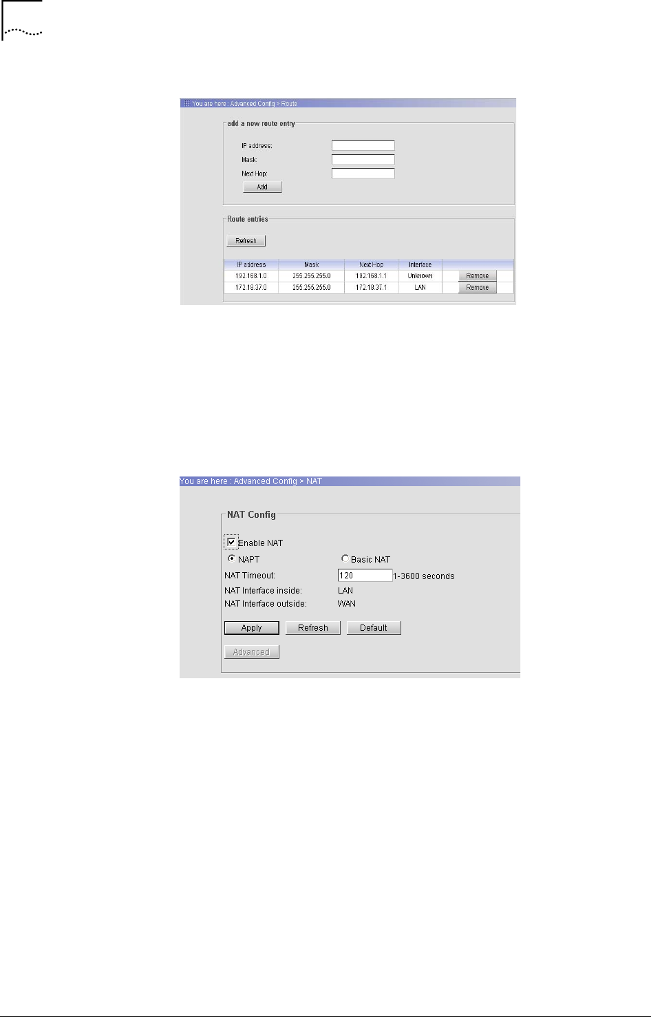
38 Chapter 4 Web-based Configuration
User Guide WA3001-S Access Point
Figure 52 Route Configuration
Enter IP address, Mask and the IP address of the Next Hop, click <Add> to
add a new route entry. The <Refresh> button is used to refresh the display
of all route entries. The <Remove> button is used to remove a route.
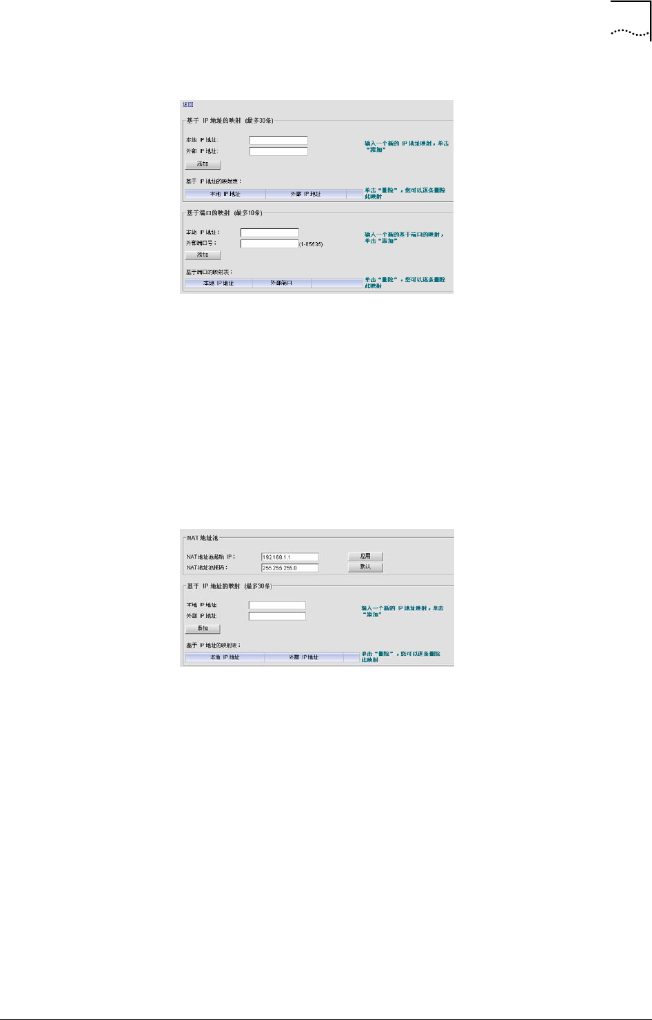
NAT Configuration
Click “Advanced/NAT”, NAT (Network Address Translation) configuration
interface is shown in Figure 53
Figure 53 NAT Configuration
Select “Enable NAT”, choose either NAPT mode or Basic NAT mode. The
range of NAT Timeout is 1 – 3600 seconds. Click <Apply> to take the
configuration effect, and then the NAT Advanced Configuration is available.
• NAPT (Network Address and Port Translation) mode configuration is
shown in Figure 54
Chapter 4 Web-based Configuration 39
WA3001-S Access Point User Guide
Figure 54 NAT/NAPT Configuration
IP Address mapping:
- Local IP address: IP address inside NAT interface
- Remote IP address: IP address outside NAT interface
Port mapping:
- Local IP address: Local IP address used for port mapping.
- External port: TCP port number used to differentiate the hosts
• NAT (Network Address Translation) advanced configuration is shown in
Figure 55.
Figure 55 NAT Advanced Configuration
NAT Address Pool:
- The starting IP address in NAT address pool: The first IP address of
an external network address pool, it is mapped to the internal
network by a way of dynamic address allocation.
- NAT Mask: the range of the address pool is defined by Mask and
the first IP address in the pool.
IP address mapping:
- Local IP address: IP address inside NAT interface.
- Remote IP address: IP address outside NAT interface.
Isolation & Filter Configuration
Click “Advanced Config/Isolation and Filter”, the configuration is shown in
Figure 56
40 Chapter 4 Web-based Configuration
User Guide WA3001-S Access Point
Figure 56 Isolation and Filter Configuration
• Isolation
- Wired-wireless Isolation: Wired users and wireless users cannot
access with each other.
- Wired Isolation: Wired users cannot access with each other.
- Wireless Isolation: Wireless users cannot access with each other.
• Config broadcast limit: Configure the broadcast restriction, the range is
1-65535, the default value is 64.
• Load balance: Enable load balance in either “User based” or “Flux
based” mode.
Click <Apply> to take the configuration effect.
• Add a MAC address to the black list: Add a MAC address to the black
list, click <Add>, the user with this MAC address will then be blocked
from accessing the AP.
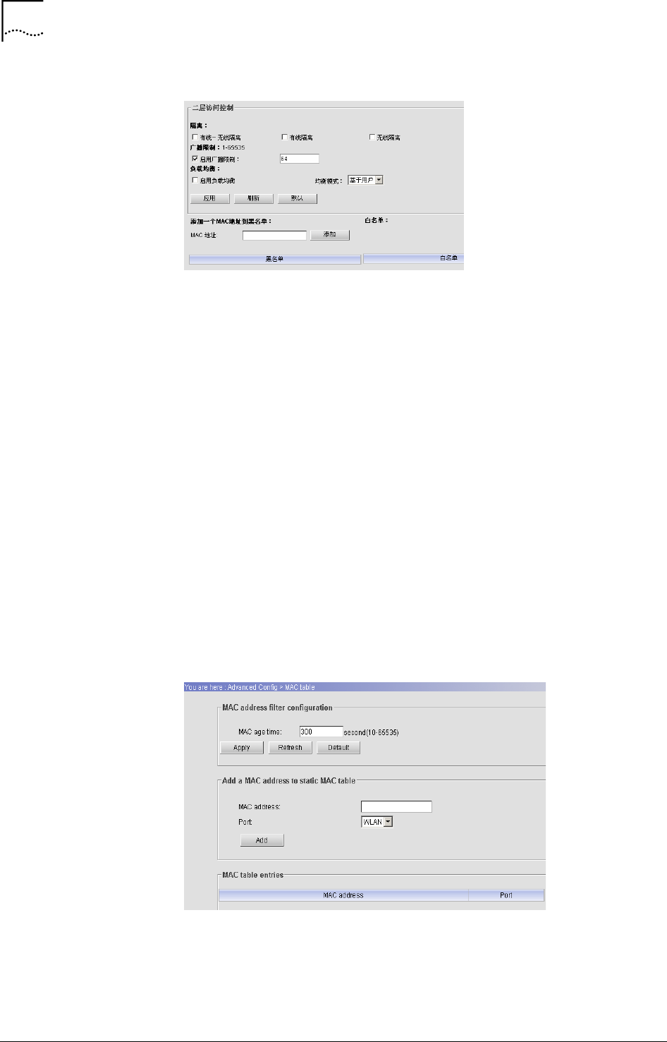
MAC Table Configuration
Click “Advanced Config/MAC Table”, the configuration interface is shown in
Figure 57.
Figure 57 MAC Table Configuration
• MAC age time: Configure the MAC address age time, the range is 10-
65535 seconds, the default is 300 seconds.
Chapter 4 Web-based Configuration 41
WA3001-S Access Point User Guide
• Add a MAC address to static MAC table: Add MAC addresses to the
MAC address table, two available ports, WLAN1/WLAN2. Click <Add>
after the configuration.
• MAC table entries: Display MAC entries.
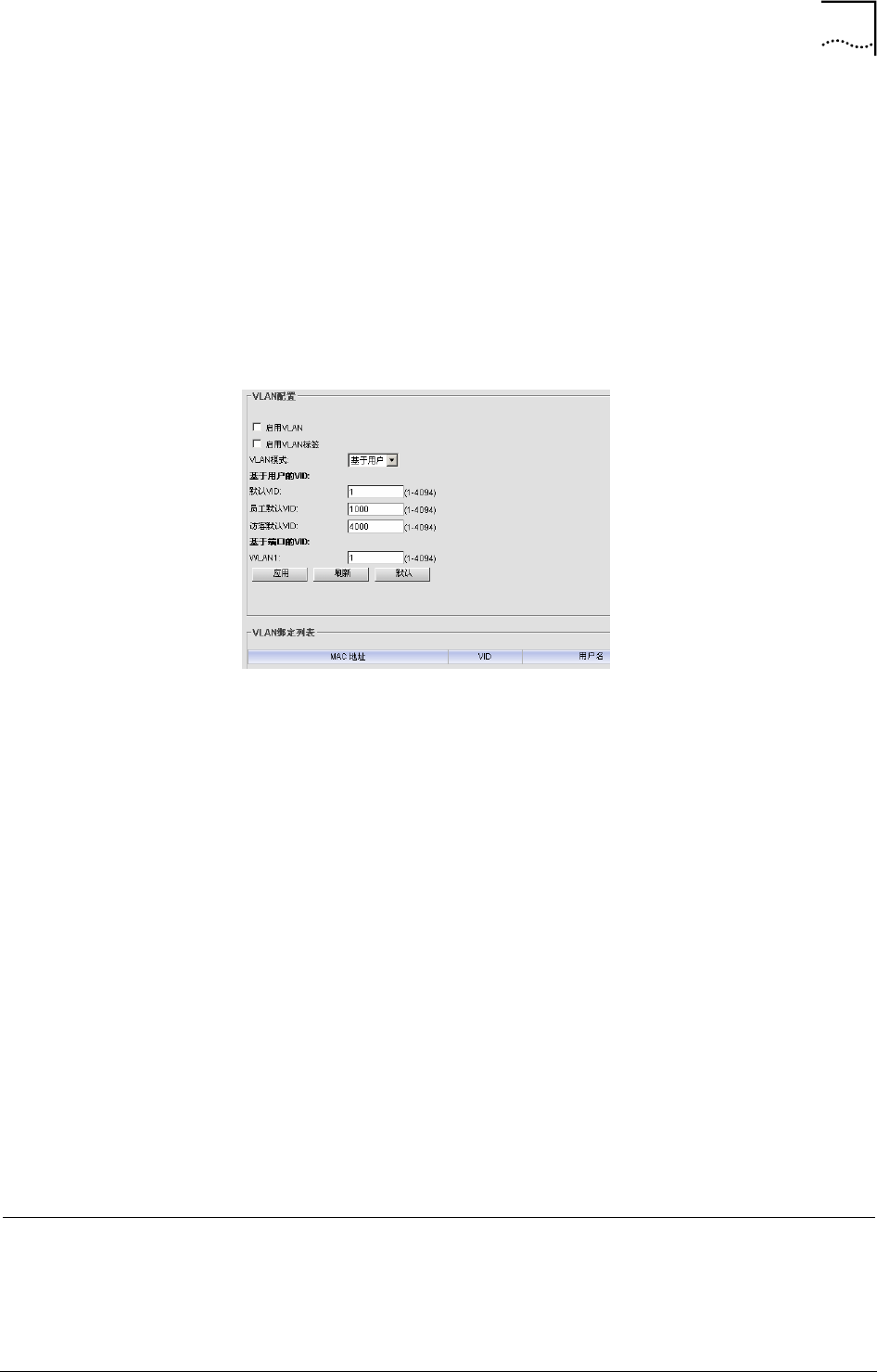
VLAN Configuration
Click “Advanced Config/VLAN”, the configuration user interface is shown in
Figure 58. VLAN ID used for differentiating users access levels depends on
access privilege. E.g. Administrators and Guests are two different groups of
users depends on their VLAN ID.
Figure 58 VLAN Configuration
• Enable VLAN: Enable the AP’s VLAN function
• To differentiate the user access privilege by enabling the VLAN tag.
• VLAN mode: Three modes are available. They are “User based”, “Port
based” and “Mix”.
• User based VID
- Default VID: The possible value are 1-4094, the default is 1.
- Employee default VID: The VLAN ID used for company employees
to access network. The possible values are 1-4094. The default
value is 1000.
- Guest default VID: The VLAN ID used for guests to access network.
The possible values are 1-4094. The default value is 4000.
• Port based VID: The usable WLAN port (WLAN1/WLAN2) is displayed
on the screen. Configure the WLAN port VLAN ID, the possible values
are 1-4094, the default value is 1.
Click <Apply> to take the configuration effect, the “VLAN bounding table”
displays the current users information bounding with VLAN.
System Configuration
WA6011 provides password change, AP Management and Upgrade in
System Configuration.
42 Chapter 4 Web-based Configuration
User Guide WA3001-S Access Point
System Information
Click “System Config/System”, the System Information configuration
interface is shown in Figure 59. It includes the following fields:
- Product Serial No.
- Hardware version
- Software version
Figure 59 System Information
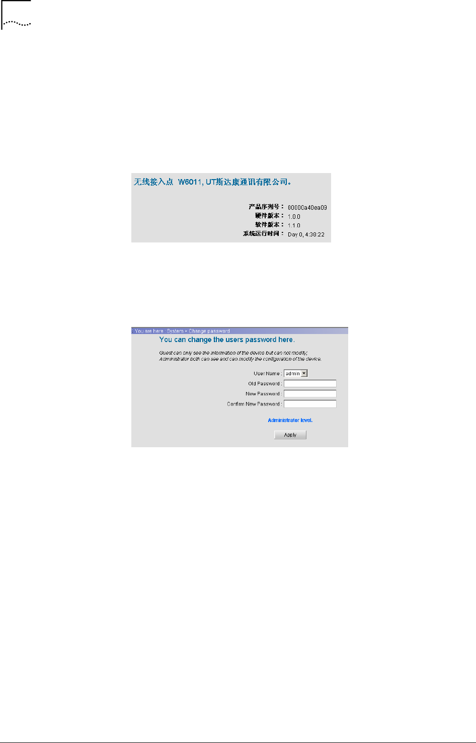
Change Password
Click “System Config/Change Password”, the configuration interface is
shown in Figure 60
Figure 60 Change Password Configuration Interface
User Name and Password can be modified. Click <Apply> to submit and
save the change
Two types of users can log in the system: admin and guest.
An “admin” has the privilege to perform all operations to the device, including
information browse, configuration and modification and so on; while a
“guest” only has the privilege to browse information.
An “admin” can modify passwords for all users in the system; while a “guest”
can only modify his own password.
Web Management Filter
Click “Advanced Config/Web Management Filter”, the configuration interface
is shown in Figure 61. This function implements the control of Web users.
Chapter 4 Web-based Configuration 43
WA3001-S Access Point User Guide
Figure 61 Web Management Filter Configuration
• Filter based on IP address
- Enable Subnet or Mainframe Filter: After activate the IP address
filter function, the only configured IP address can access the AP.
- IP Address/Subnet Mask: A mainframe has one only IP address
input, a subnet mask needs one IP address and a subnet mask.
• Port based Network Access (Forbidden)
- Prohibit WAN Port Management: User is unable to implement the
management through WAN port after it is activated.
- Prohibit Wireless Port Management: Wireless users are not able to
access the AP after it’s activated.
Click <Apply> to submit and save the change
SNMP Configuration
Click “Advanced Config/SNMP Config”, it contains SNMP agent, SNMP end
user filter and SNMP trap configuration.
• SNMP agent config/SNMP end user filter configuration interface is
shown in Figure 62
Figure 62 SNMP Agent/SNMP End User Filter Interface
SNMP agent Setting:
- Enable SNMP agent: Activate SNMP agent function
- Read-only Community Name: The default is “public”, 1-64
alphanumeric letters.
44 Chapter 4 Web-based Configuration
User Guide WA3001-S Access Point
- Read-write community Name: The default is “private”, 1-64
alphanumeric letters.
- The system name, location name and principle name can also be
configured, 0-255 alphanumeric letters.
SNMP End-user Filter
The maximum SNMP end-user can be configured is 4. The only configured
IP address can access AP through SNMP.
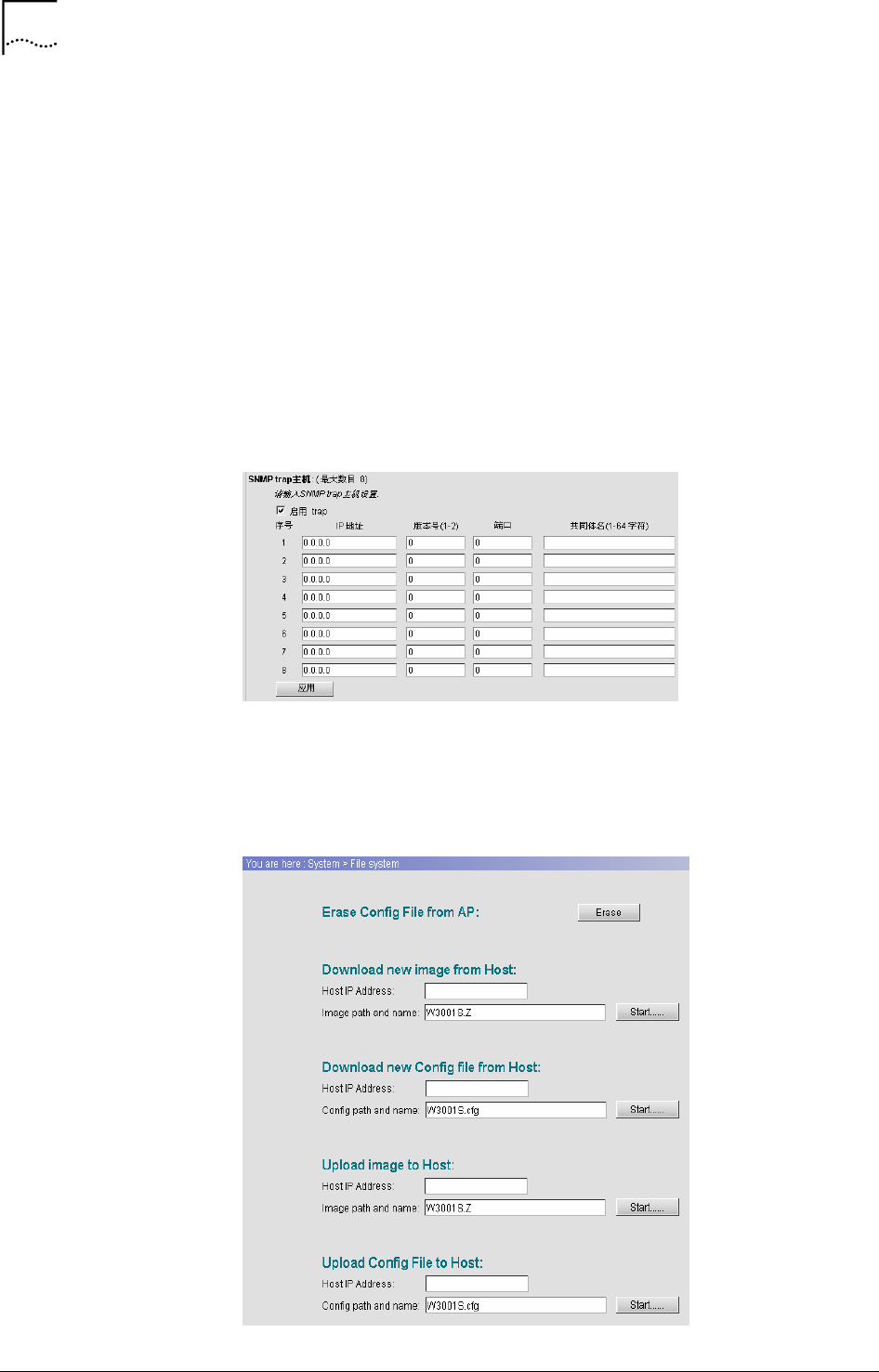
• SNMP trap host (Maximum number is 8)
The configuration interface is shown in Figure 63. There are totally 8 IP
addresses can be configured for alarm server. If no IP address was
configured for SNMP end-user, which means that all IP addresses can
access AP through SNMP.
Figure 63 SNMP Trap Configuration
File System Management
Click “Advanced Config/File System”, the configuration interface is shown in
Figure 64.
Figure 64 File System Configuration
Chapter 4 Web-based Configuration 45
WA3001-S Access Point User Guide
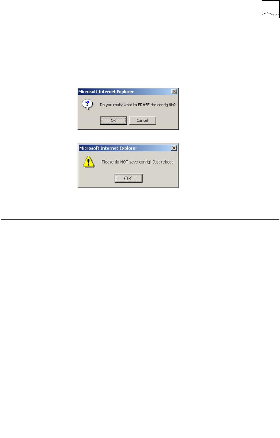
Erase Config File from AP: Click <Erase> to erase the current configuration
file from the AP; a dialog box will appear as shown in Figure 65. Click <OK>
and a message box will appear as shown in Figure 66. It prompts the
rebooting device and initiates the configuration erase.
Figure 65 Erase Configuration File Dialog Window
Figure 66 Reboot Message Dialog Window
For system file (including image and configuration file) management, specify
the host IP address, set the system file path and file name. Click <Start> to
start the download/upload AP Image or Config File.
Statistic Information
This section will introduce the system statistic information of AP
Wireless Port (WA6011)
Click “Statistic/Wireless Port”, the configuration user interface will be shown
in Figure 67.
46 Chapter 4 Web-based Configuration
User Guide WA3001-S Access Point
Figure 67 Wireless Port Statistic Information
ADSL Statistic Information (WA6012)
WA6012 ADSL statistic Information is shown in Figure 68
Chapter 4 Web-based Configuration 47
WA3001-S Access Point User Guide
Figure 68 ADSL Statistics Information
WAN/LAN Interface
Click “Statistic/WAN/LAN Interface”, the statistic information of WAN and
LAN interfaces are shown in Figure 69.
Figure 69 WAN/LAN Interface Statistics Information
48 Chapter 4 Web-based Configuration
User Guide WA3001-S Access Point
DHCP Server
Figure 4-44 shows DHCP related information. Figure 70 describes the
related parameters.
Figure 70 DHCP Server Statistics Information
DHCP Relay
Click “Statistic/DHCP Relay”, Figure 71 shows the DHCP Relay statistic
information.
Figure 71 DHCP Relay Statistic Information
RADIUS Client
Click “Statistic/RADIUS Client”, Figure 72 displays the RADIUS Client
statistic information.
Chapter 4 Web-based Configuration 49
WA3001-S Access Point User Guide
Figure 72 RADIUS Client Statistic Information
ARP
Click “Statistic/ARP”, Figure 73 displays ARP statistic information.
Figure 73 ARP Statistic Information
Route
Click “Statistic/Route”, the current route information is shown in Figure 74.
Figure 74 Route Statistic Information
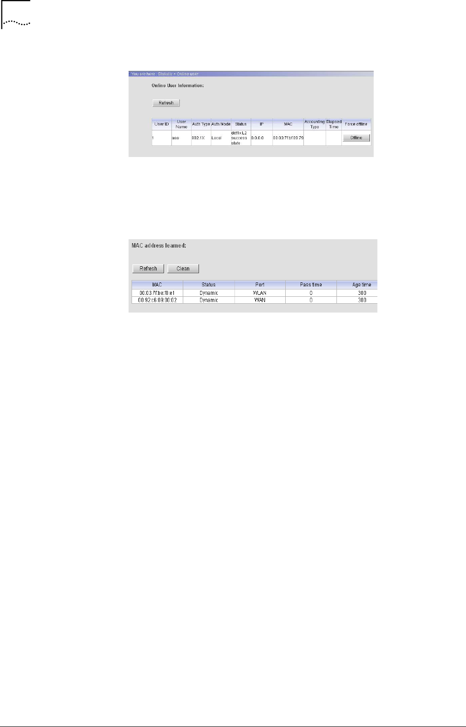
Online User
Click “Statistic/Online User”, Figure 75 shows online user statistic
information. Click “Force Offline”, the user will be disconnected in force.
50 Chapter 4 Web-based Configuration
User Guide WA3001-S Access Point
Figure 75 Online User Statistic Information
MAC Address
Click “Statistic/MAC Address”, Figure 76 shows MAC addresses learnt by
the AP.
Figure 76 MAC Address Statistic Information
WA3001-S Access Point User Guide
5 Typical Configuration Examples
AP in Bridge Mode
Take WA6012 as example:
Configuration Information:
1 AP working mode: Bridge mode
2 The default IP address for AP’s LAN interface is 172.18.37.1; Subnet
mask is 255.255.255.0
3 Set ESSID to “AP123”, set Channel to 1
4 Enable WEP Encryption, use key1: mykey
5 VPI/VCI:0/35
6 Wireless network card configuration:
SSID: AP123
Use key1: mykey
The network topology refers to Figure 2.
Detailed Instructions:
Step 1: Refer to section “Login AP” in Chapter 3.
Step 2: Click the “Guide” link to go to the “Set AP mode” configuration
window. The default mode is Bridge mode, then click <next>.
- The “Set LAN interface” configuration window appears, use the
default IP address, then click <next>.
5
52 Chapter 5 Typical Configuration Examples
User Guide WA3001-S Access Point
- The “Set wireless port” configuration window appears. Set SSID to
“AP123”, Channel to “1”.
- Click <next>, the popped up window below prompts the completion
of the configuration. Click <finish>, AP will reboot. The configuration
will be effective after rebooting.
Step 3: Set the WEP encryption for the AP
- Click “Basic Config/Wireless Port 1”, enable WEP encryption with
64-bit, select “Alphabetical” as a key format, enter “mykey” as the
key1 value
Chapter 5 Typical Configuration Examples 53
WA3001-S Access Point User Guide
- Click <Apply>, the system will remind you to save the configuration,
and then restart the AP in order to take effect the configuration
Step 4: Click “Basic Config/ADSL Config”, set PVC to 0/35, enable “Reboot
ADSL module while reconnection”, then click <apply>.
Step 5: In the “General” of the WNIC2010 Utility, set the SSID value to the
same value as the AP
Step 6: In the “Security/Pre-Shared Key” of the WNIC2010 utility, enter
“mykey” as the Key1 value
54 Chapter 5 Typical Configuration Examples
User Guide WA3001-S Access Point
AP in Router Mode
Take WA6011 as example:
Description:
This example setup is used for establishing a small range network consisting
of less than 10 users. AP supports IEEE 802.1x. There has a remote
Radius/AAA (Authentication, Authorization and Accounting) server.
AP Configuration Information:
- AP working mode: Route mode
- IP address for AP’s WAN interface: assigned through DHCP server
- IP address for AP’s LAN interface: the default one is 172.18.37.1
- AP acts as a DHCP server to assign the IP addresses for the
WLAN
- Managed by NAT
- Configure the Radius server
- Enable the 802.1x authentication of AP, set the maximum number
of online users to 10
Detailed Instruction:
Step 1: Set the working mode to “Route mode” through the “Guide” link, get
the WAN interface IP address through DHCP server, user the default IP
address for LAN interface, and configure SSID. Click <Apply>, the pop-up
window will remind user to save and reboot the AP to effect the configuration.
Step 2: Enable the DHCP Server through the “Basic Config/DHCP Server
Configuration” link, set Network IP, Network Mask, DNS server and other
parameters. Set the Gateway IP address to the one for AP LAN port, and
then click <Apply>.
Chapter 5 Typical Configuration Examples 55
WA3001-S Access Point User Guide
Step 3: Through the “Advanced Config/RADIUS Client” link to set the IP
address for the remote Radius Server. If the authentication is enabled on
Radius server, the same authentication has to be set for AP. Click on the
<Apply> button to effect the configuration
Step 4: Enable NAT configuration through the “Advanced Config/NAT” link.
Step 5: Through the “Advanced Config/Authentication” link to go to the
“Authentication” configuration window. Enable the 802.1x authentication, set
the Authentication mode to “Remote”, set the max online user number to
“10”.
56 Chapter 5 Typical Configuration Examples
User Guide WA3001-S Access Point
Step 6: For the detail of SSID configuration in client wireless network card,
please refer to the section “AP in Bridge Mode” in Chapter 5.
AP in P2P Mode
Take WA6012 as example:
Configuration Information:
Set the working mode of AP-1 and AP-2 to Bridge mode, connect AP-1 to
the network through its uplink, AP-2 connects to the network through AP-1.
For example, wireless bridging can be done through network card 1 of AP-1
and AP-2
AP-1 Configuration:
- Set the working mode to Bridge mode
- Through the “Advanced Config/Wireless Port 1” link, select
“Repeater mode”, click <apply>, the pop-up window will remind
user to save and reboot the AP to effect the configuration.
- Click <OK>, the WDS configuration user interface appears. Add
AP-2’s MAC address into the “MAC address” field. Click <Add>, the
address will be displayed in the MAC address table.

Chapter 5 Typical Configuration Examples 57
WA3001-S Access Point User Guide
AP-2 Configuration:
Set the working mode to Bridge mode, select “Repeater Mode” in “Advanced
Config/Wireless Port 1” configuration.
Connect the AP-2 to the wired network through its Ethernet port when AP-2
is WA6011, Meanwhile, AP can implement its network coverage by
configuring the other network card. For the details of LAN interface IP
address, SSID and other parameter configurations, please refer to the
section “AP in Bridge Mode” in Chapter 5

WA3001-S Access Point User Guide
6 Term and Acronym List
These terms and acronyms are used throughout the UTStarcom 4007 SS7
Signaling Gateway documentation. While not all terms in this list are used in
this particular document, the complete list is provided to ensure fast access
to the definition of these terms regardless of how they are encountered.
AP Access Point
CLI Command Line Interface
DHCP Dynamic Host Configuration Protocol
IEEE Institute of Electrical and Electronics Engineering
LAN Local Area Network
MAC Media Access Control
NAT Network Address Translation
NAPT Network Address Port Translation
PPPoE PPP over Ethernet
SSID Service Set Identifier
WEP Wired Equivalent Privacy
WDS Wireless Distribution System
WLAN Wireless Local Area Network
6

WA3001-S Access Point User Guide
1 Technical Specification
Product WA6011/6012
Uplink WA6011: RJ45, 10/100Mbps Adaption;
WA6012: RJ11, ADSL interface
Auto Fall Back Rate Options 802.11b: 11Mbps & 5.5Mbps CCK, 2Mbps DQPSK, 1mbps DBPSK
802.11g: 54, 48, 36, 24, 18, 12, 9, 6Mbps (108Mbps in Super G
mode)
Standard Compliance
IEEE 802.11b
IEEE 802.11g
IEEE 802.3
IEEE 802.1x
Operational Frequency Range North America/FCC: 2.412~2.462GHz (11 channels)
China/Europe/ETSI: 2.412~2.472GHz (13 channels)
Radio Frequency Output Power 4 adjustable levels within 400mw
Sensitivity
-73dBm@54Mbps PER< 8% OFDM
-90dBm@11Mbps PER< 8% CCK
-92dB @6Mbps PER< 8% OFDM
-95dBm@1Mbps PER< 8% CCK
Coverage Outdoors: >500m
Power Supply AC: 220(±20%)V 50~60Hz(±20%)
PoE power Supply (WA6011): Cat5 x 2, 48V/1.2A adapter
Power Consumption Transmission: 30W
Reception: 25W
Operation Temperature -33 °C~ 55°C
Storage Temperature -40°C ~ 80°C
Humidity 0~90%
Waterproof Level 5th level
Antenna External, various antennae can be assembled
Dimensions 239(198)mm x 198(158)mm x 42mm (LxW.H)
Weight 2050g
EMC/EMI
CE mark:
EN55022 (1997) Class A.
EN55024 (1998)
EN61000-4-2/3/4/5/6/11
EN61000-2-2 Class A.
EN61000-2-3
FCC CFR 47 part 15 Class A(USA EMC standard)
VCCI Class A
CISPR Class A
7

UTStarcom Inc. USA
1275 Harbor Bay Parkway Alameda, CA 94502, USA
Tel: 510-864-8800 Fax: 510-864-8802
http://www.utstar.com
Federal Communication Commission Interference Statement
This equipment has been tested and found to comply with the limits for a Class B digital device,
pursuant to Part 15 of the FCC Rules. These limits are designed to provide reasonable
protection against harmful interference in a residential installation. This equipment generates,
uses and can radiate radio frequency energy and, if not installed and used in accordance with the
instructions, may cause harmful interference to radio communications. However, there is no
guarantee that interference will not occur in a particular installation. If this equipment does cause
harmful interference to radio or television reception, which can be determined by turning the
equipment off and on, the user is encouraged to try to correct the interference by one of the
following measures:
- Reorient or relocate the receiving antenna.
- Increase the separation between the equipment and receiver.
- Connect the equipment into an outlet on a circuit different from that
to which the receiver is connected.
- Consult the dealer or an experienced radio/TV technician for help.
This device complies with Part 15 of the FCC Rules. Operation is subject to the following two
conditions: (1) This device may not cause harmful interference, and (2) this device must accept
any interference received, including interference that may cause undesired operation.
FCC Caution: Any changes or modifications not expressly approved by the party responsible for
compliance could void the user's authority to operate this equipment.
IMPORTANT NOTE:
FCC Radiation Exposure Statement:
This equipment complies with FCC radiation exposure limits set forth for an
uncontrolled environment. This equipment should be installed and operated with
minimum distance 20cm between the radiator & your body.
This transmitter must not be co-located or operating in conjunction with any other
antenna or transmitter.
IEEE 802.11b or 802.11g operation of this product in the U.S.A. is firmware-
limited to channels 1 through 11.