UTT TECHNOLOGIES REG01-UTT Router User Manual
SHANGHAI UTT TECHNOLOGIES CO., LTD. Router
UserManual.wiki
>
UTT TECHNOLOGIES
>
REG01 UTT User Manual
User Manual
Navigation menu
Upload a User Manual
Namespaces
Wiki Guide
HTML
PDF
Info
Views
User Manual
Discussion / Help
Navigation
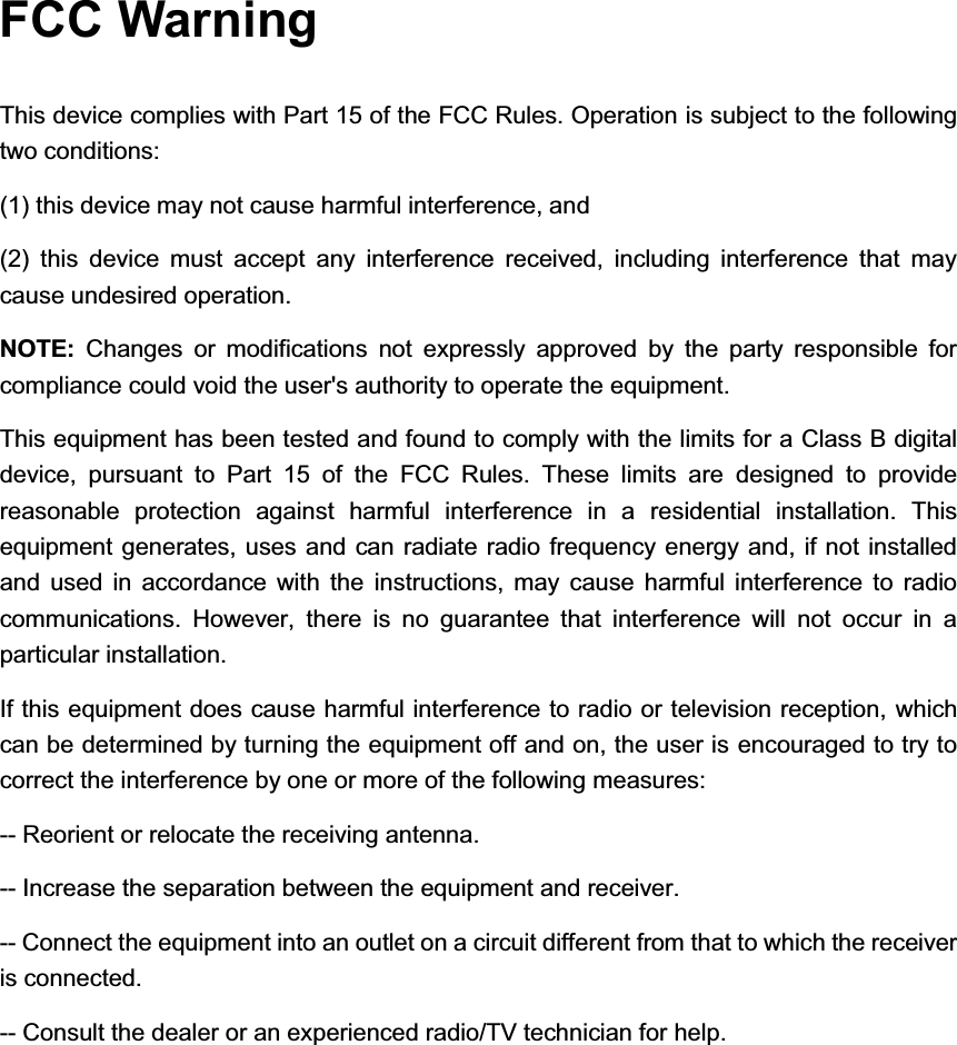
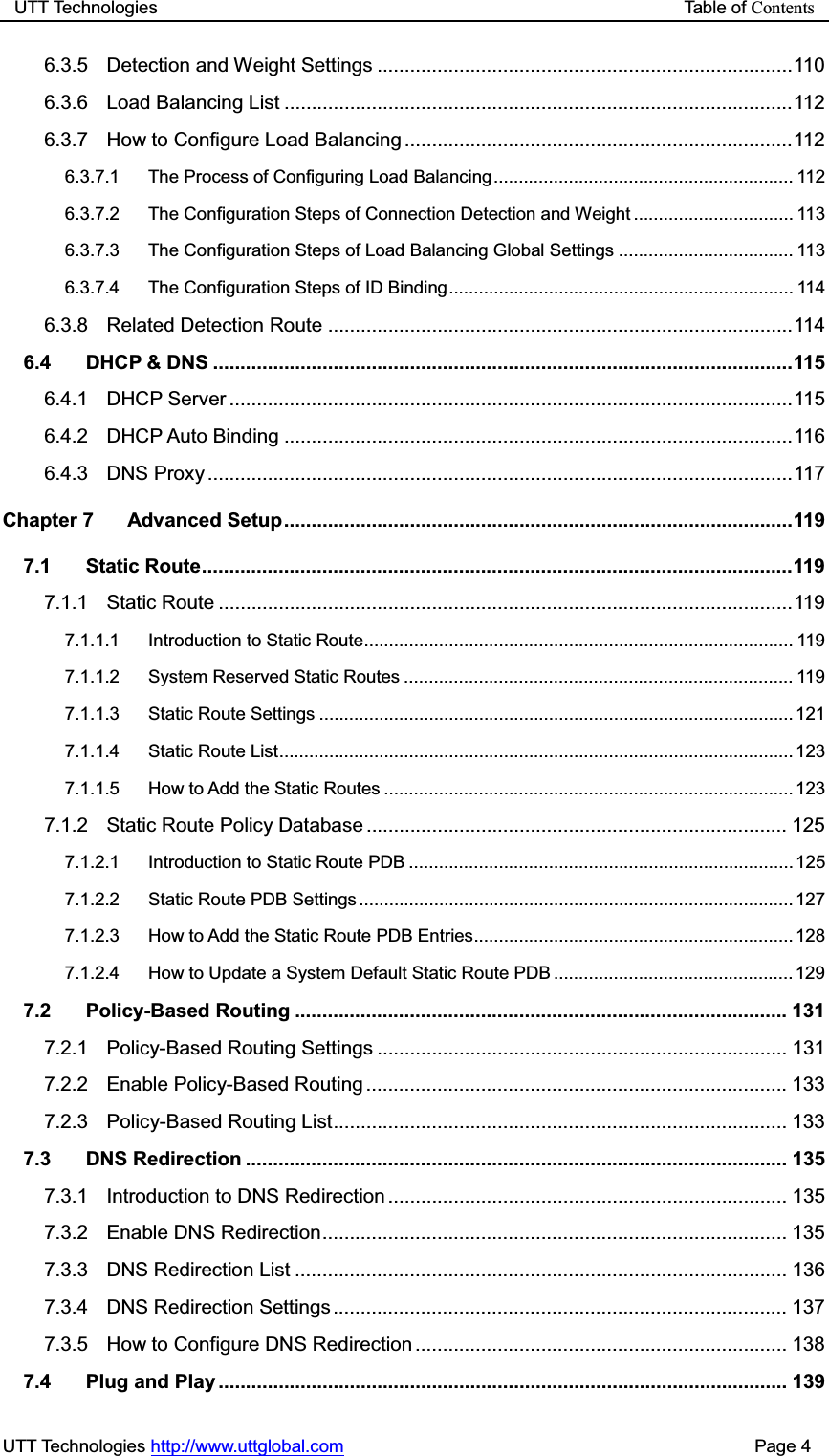
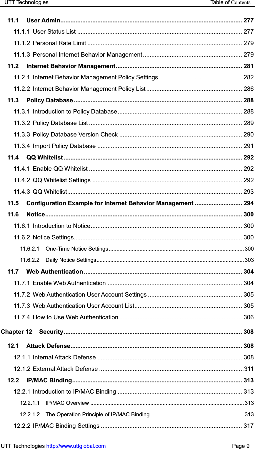

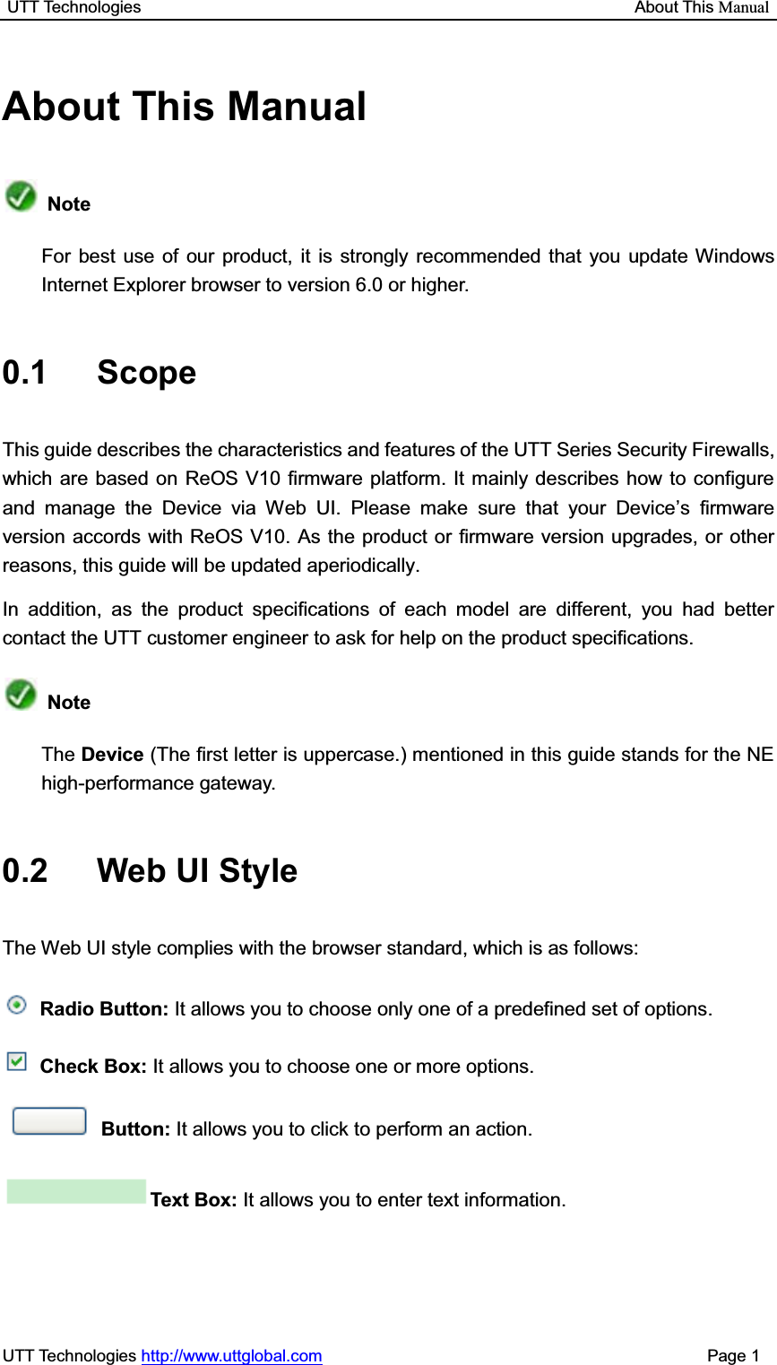
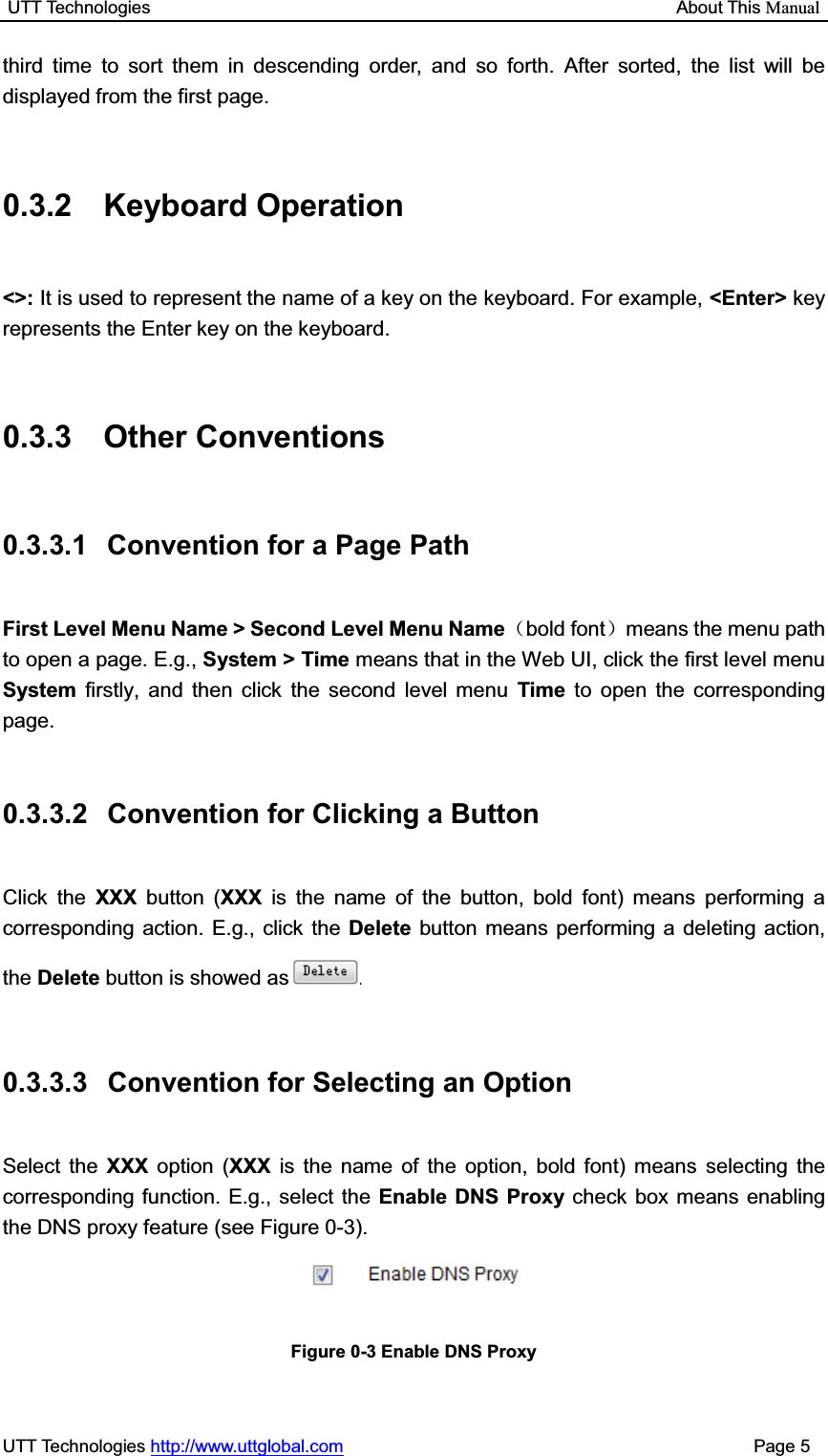
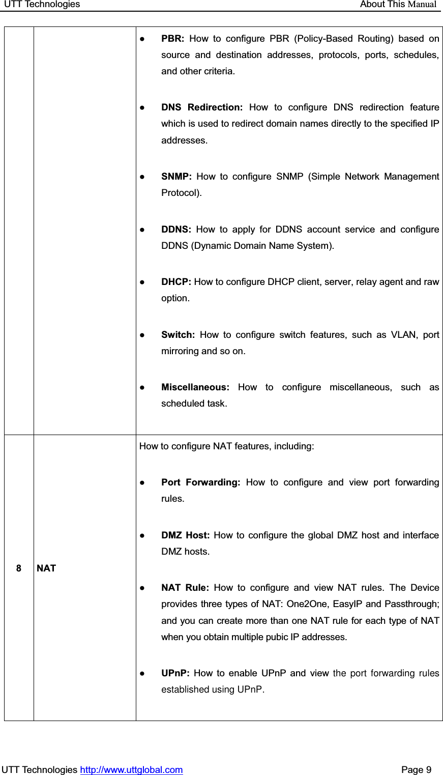
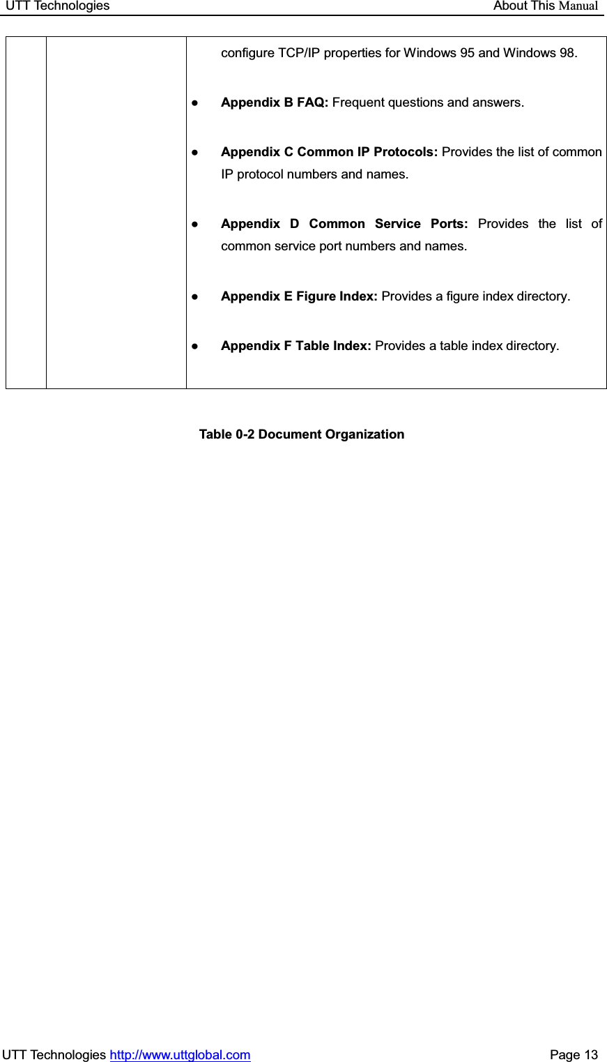
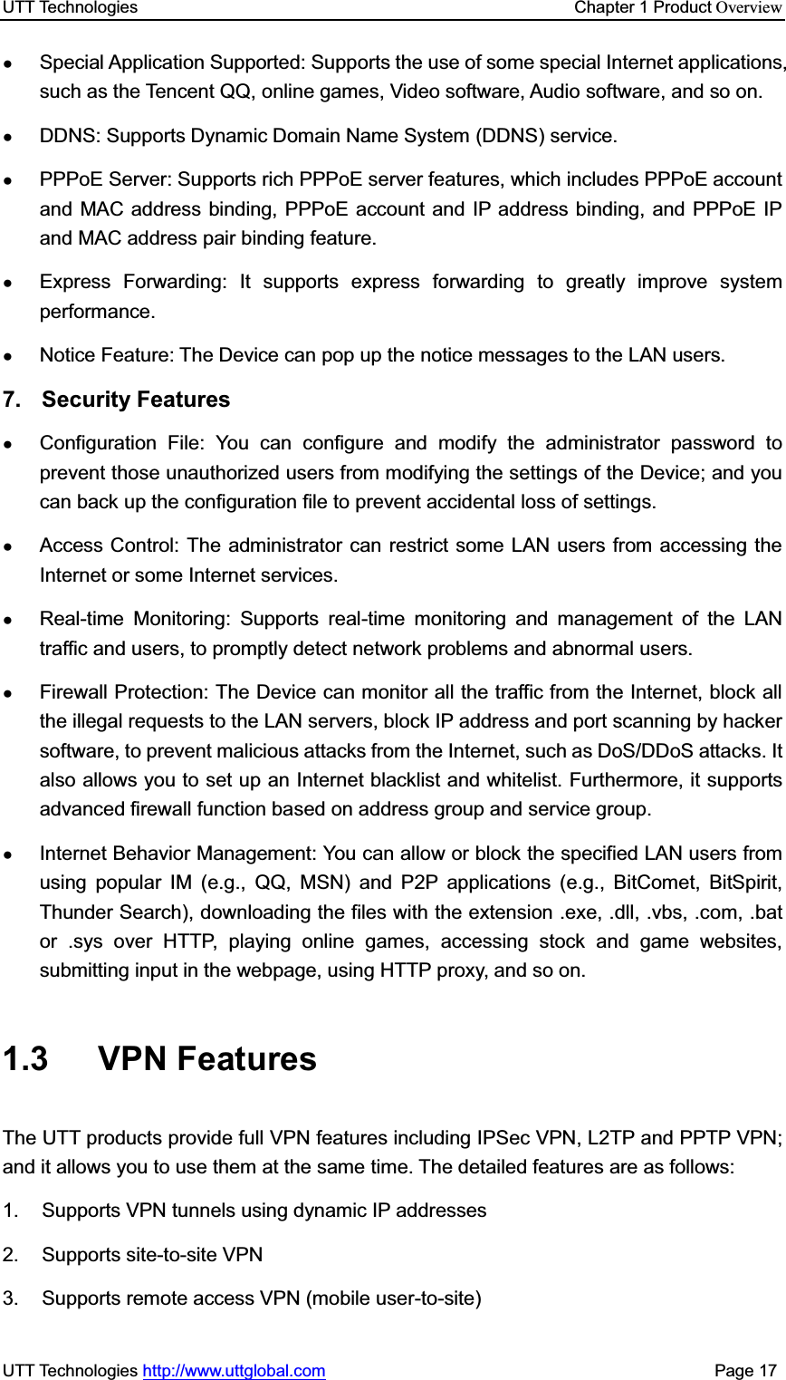
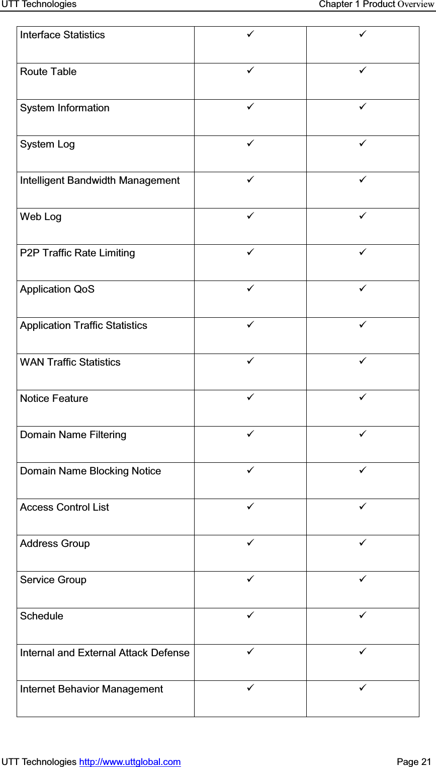
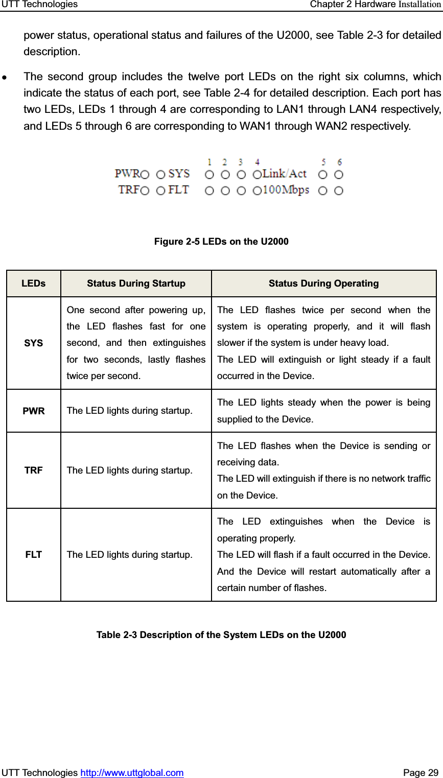
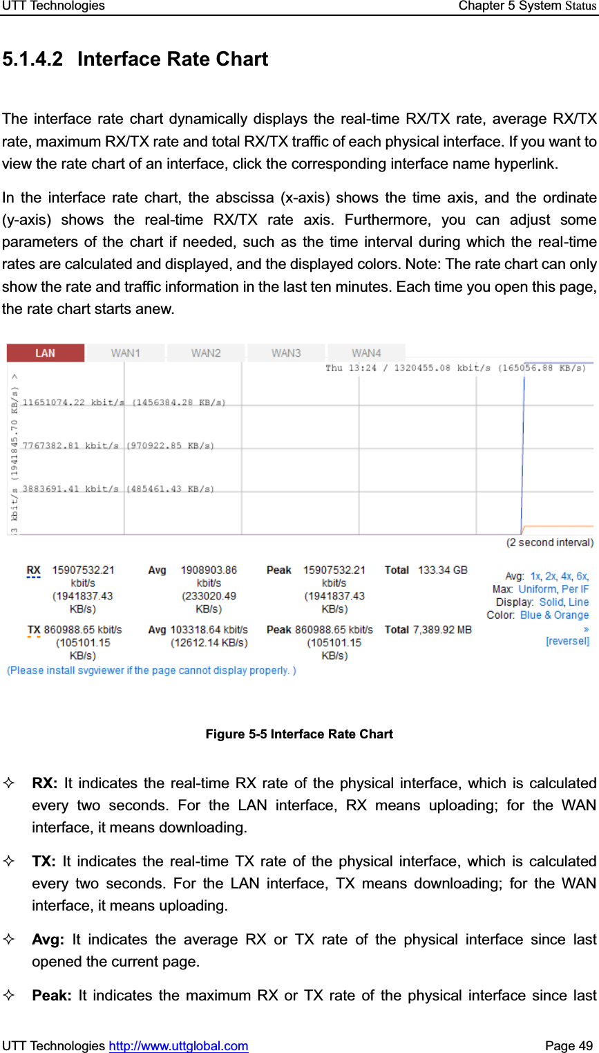

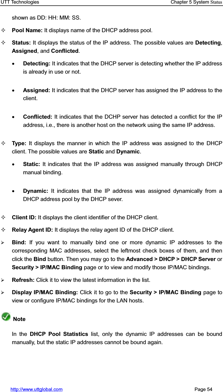
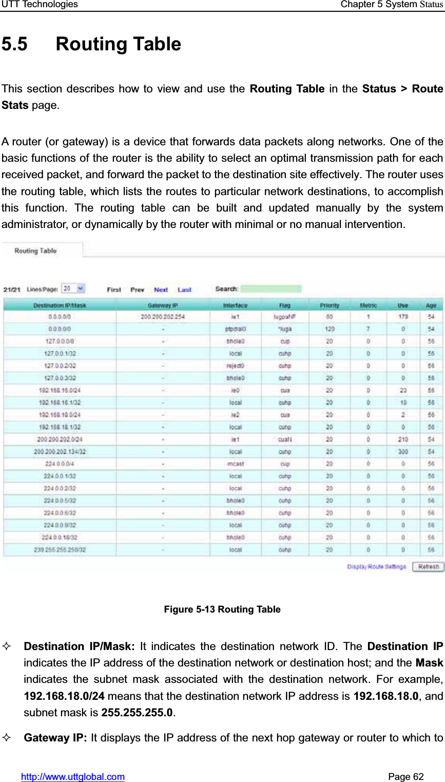

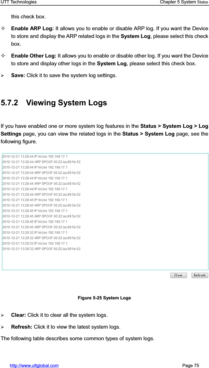
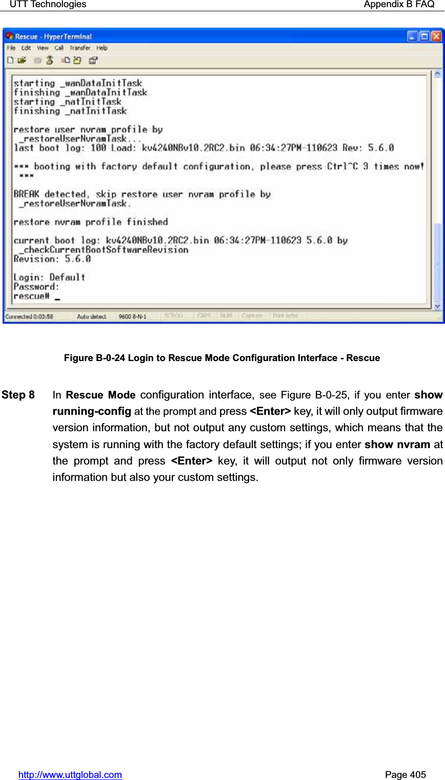
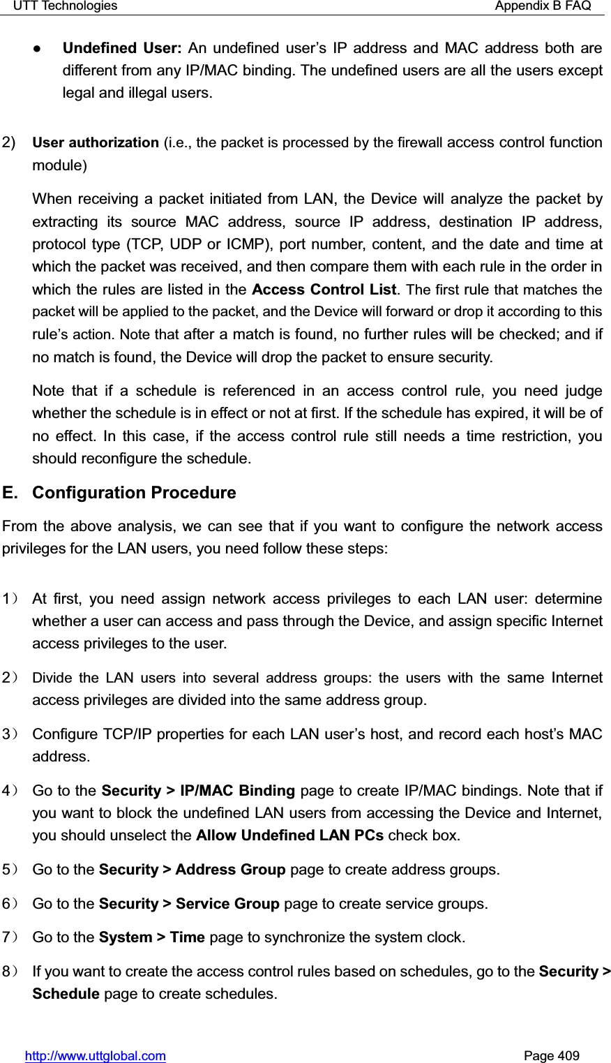
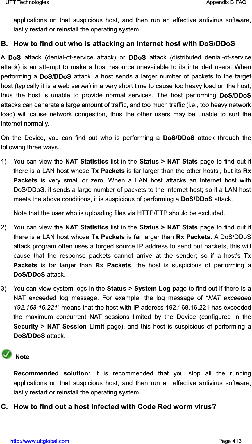
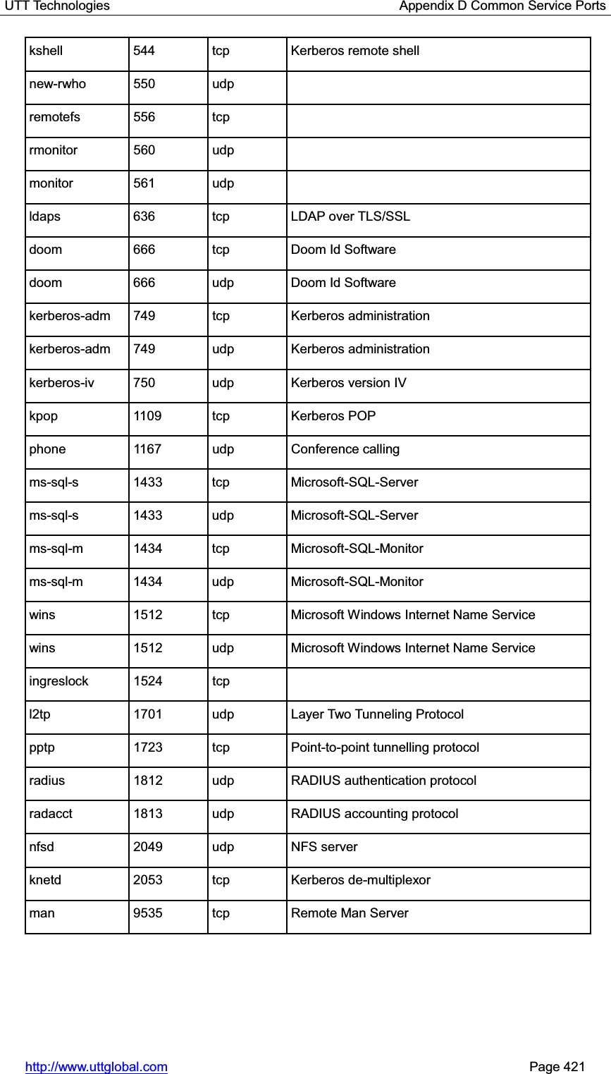
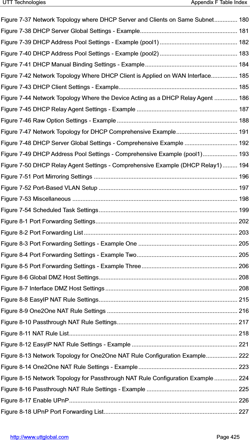
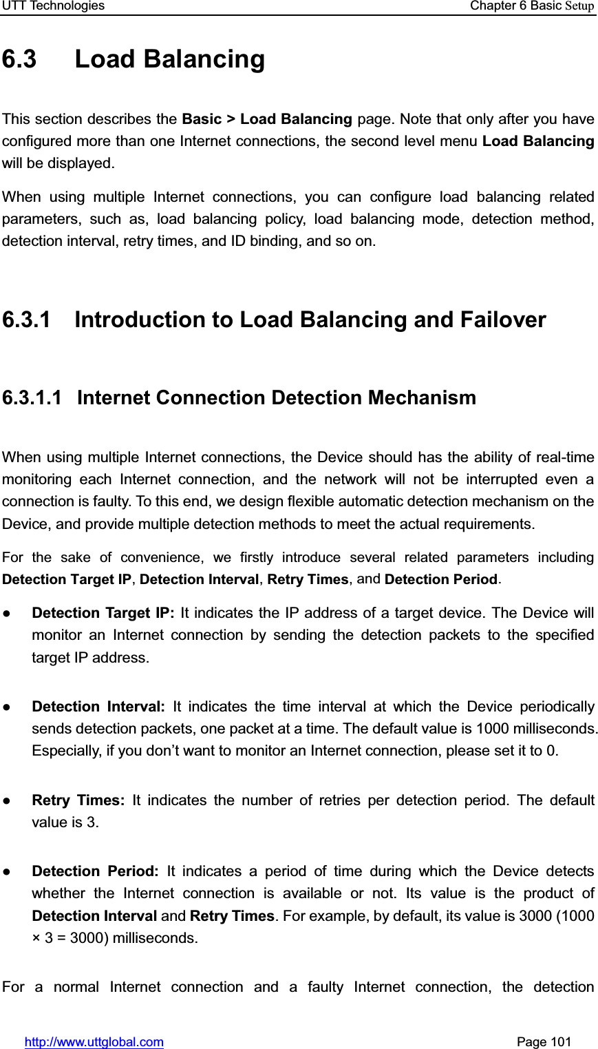
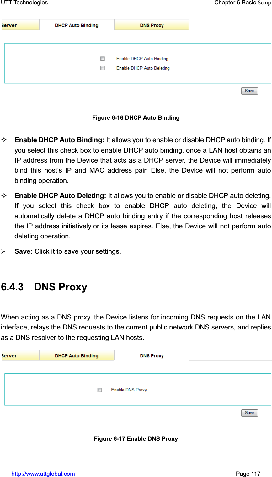
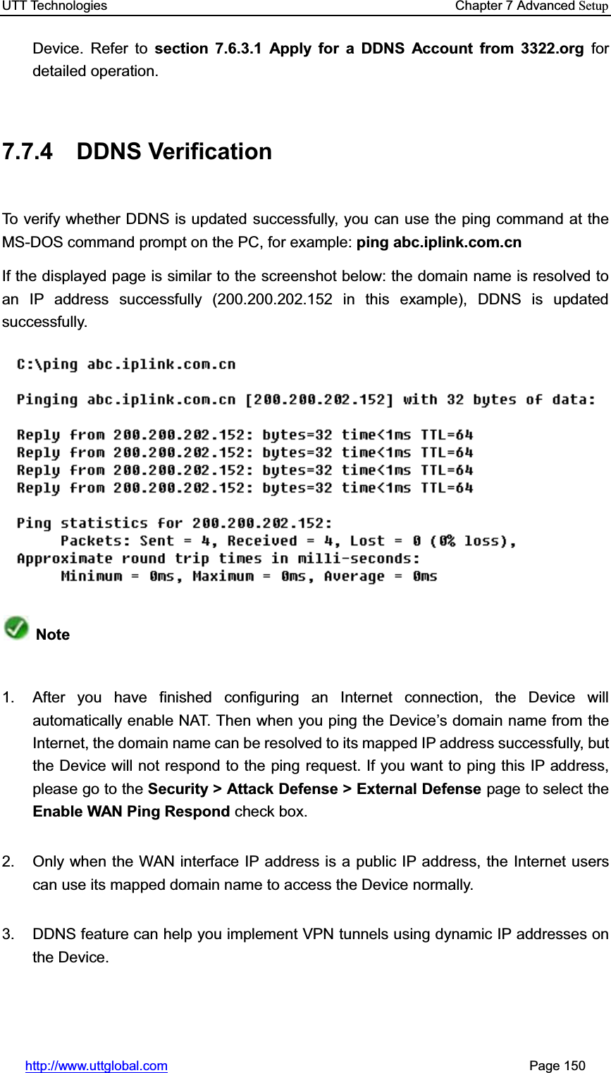
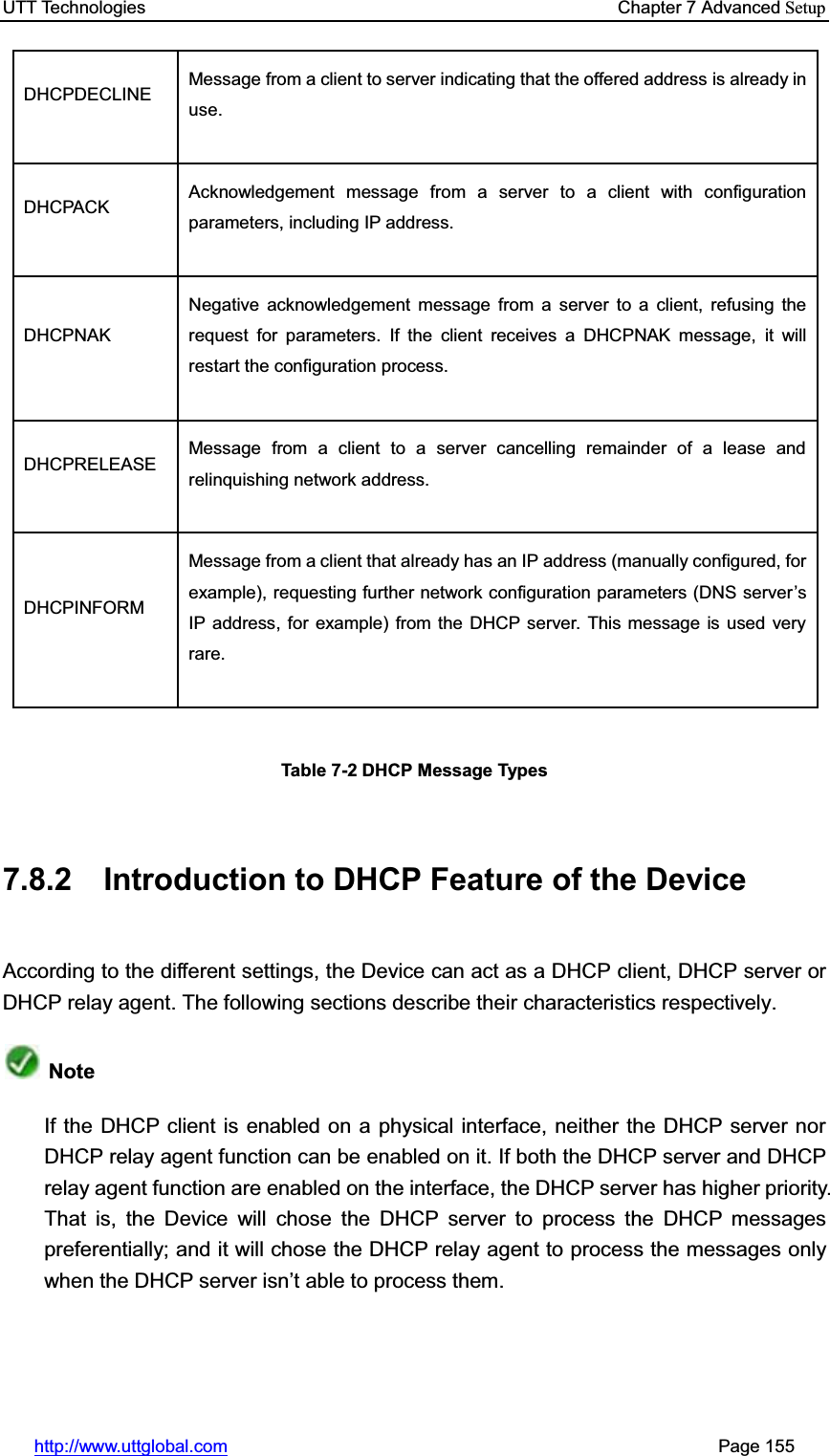
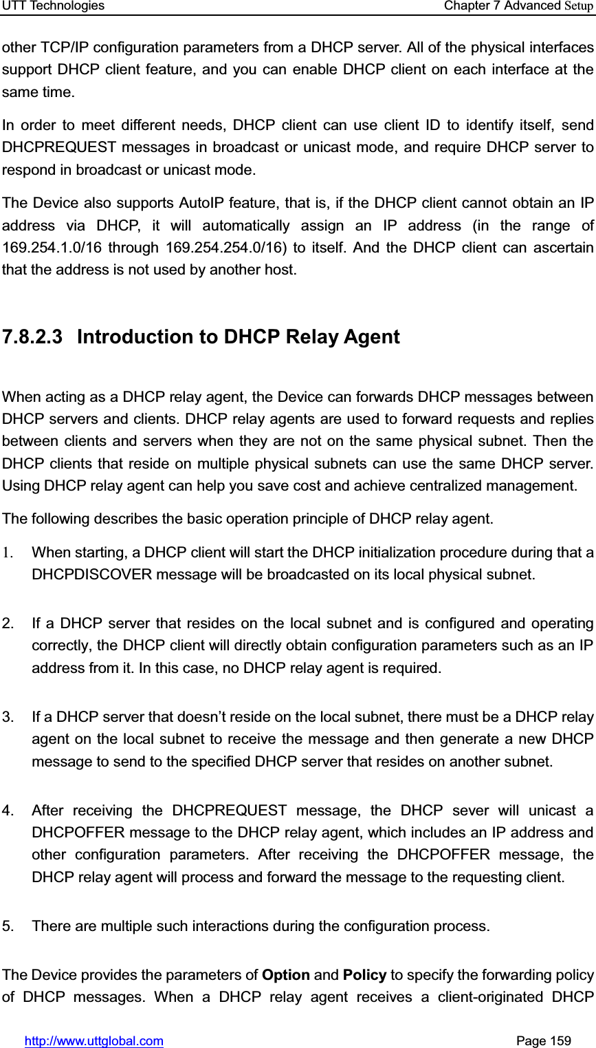
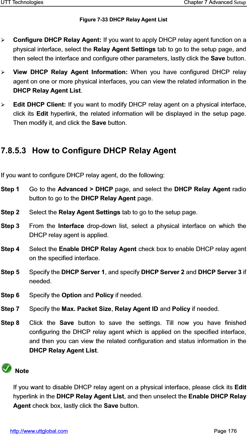
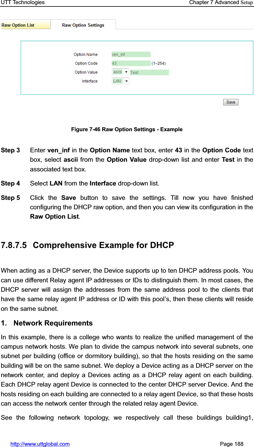
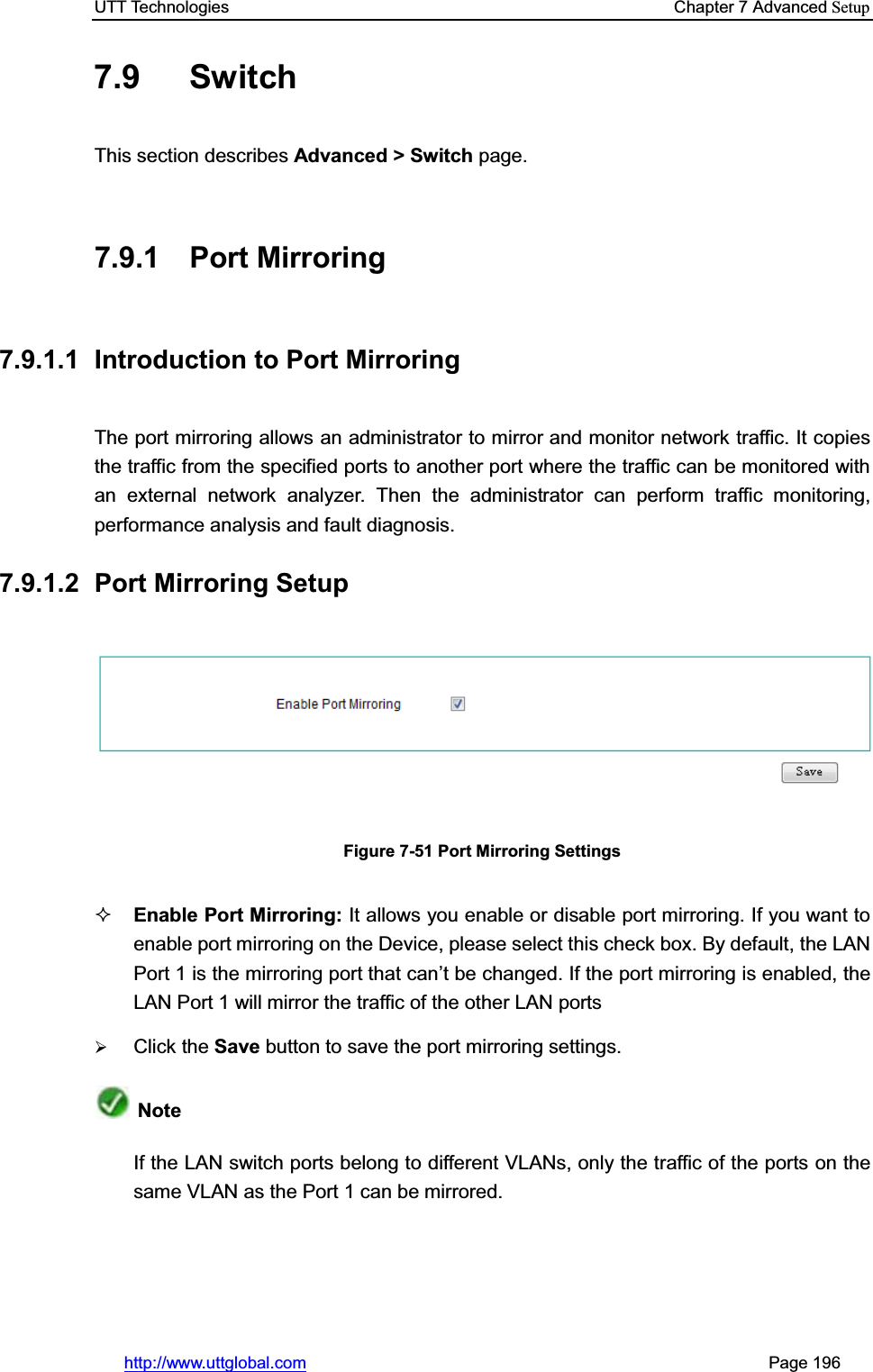
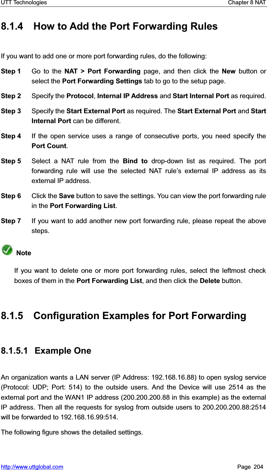
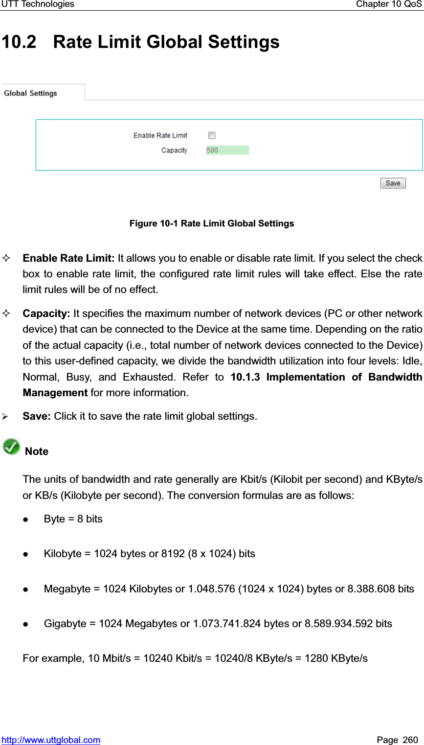
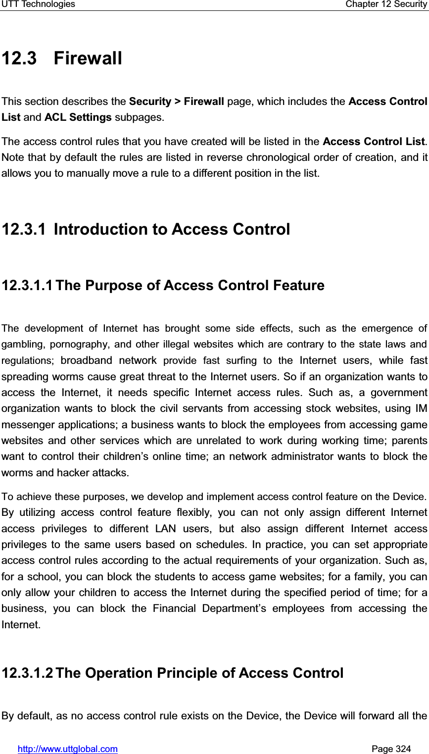
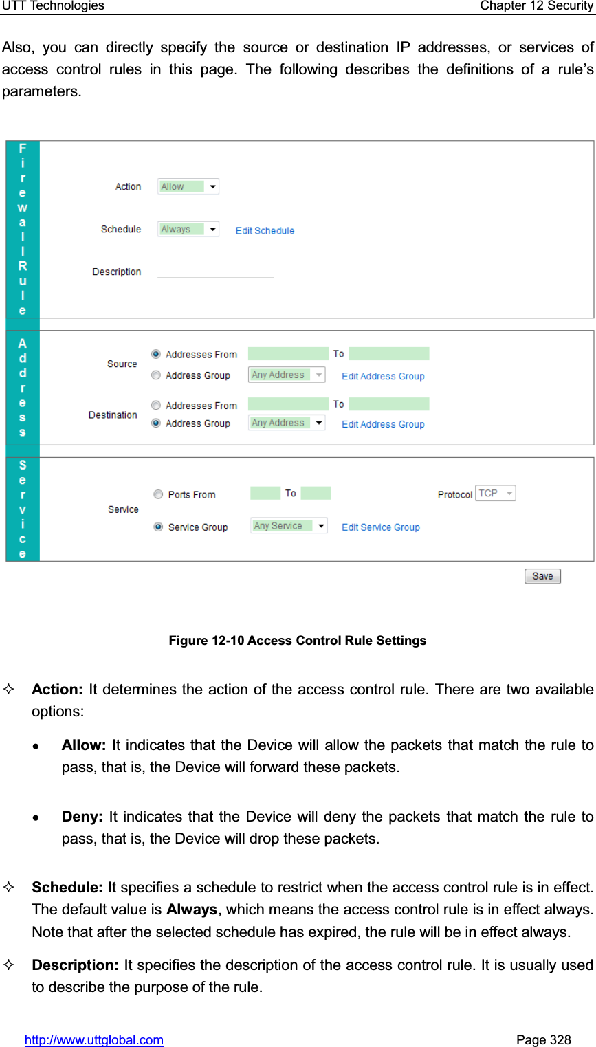
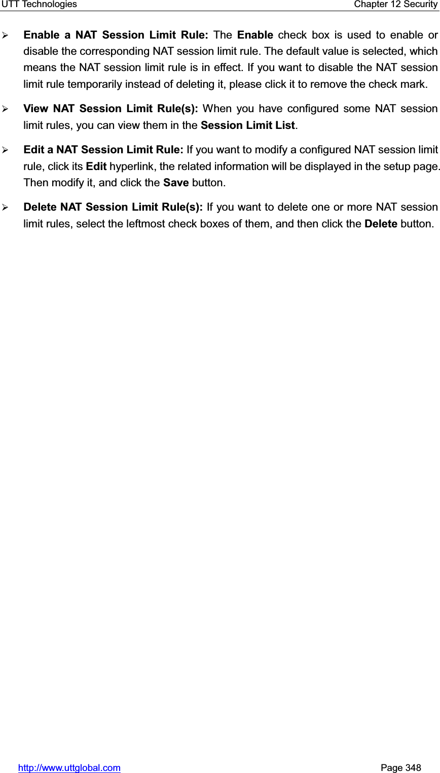
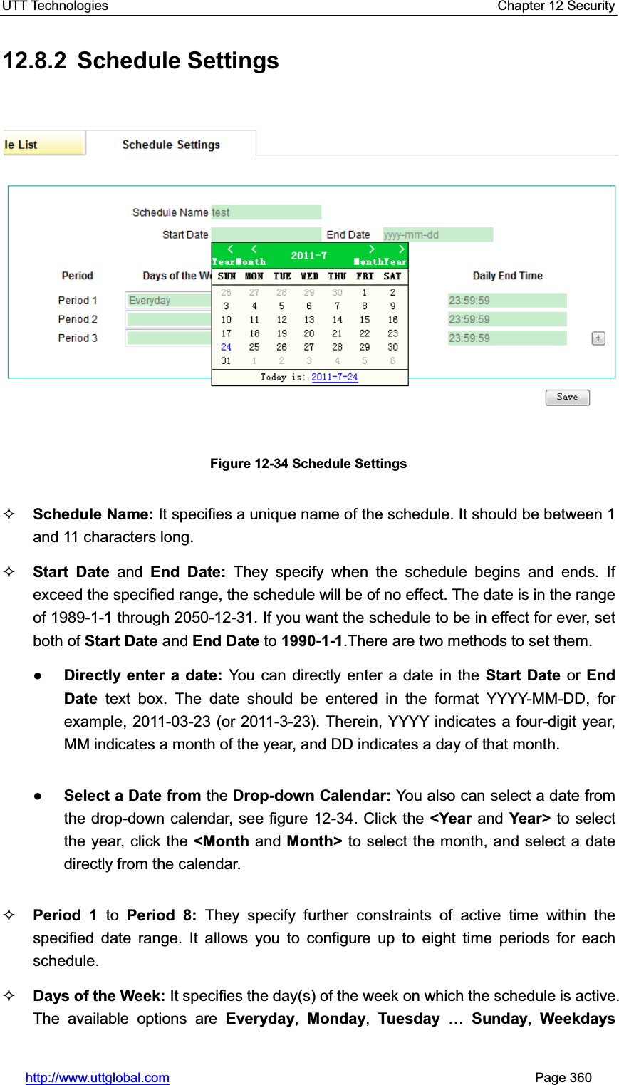
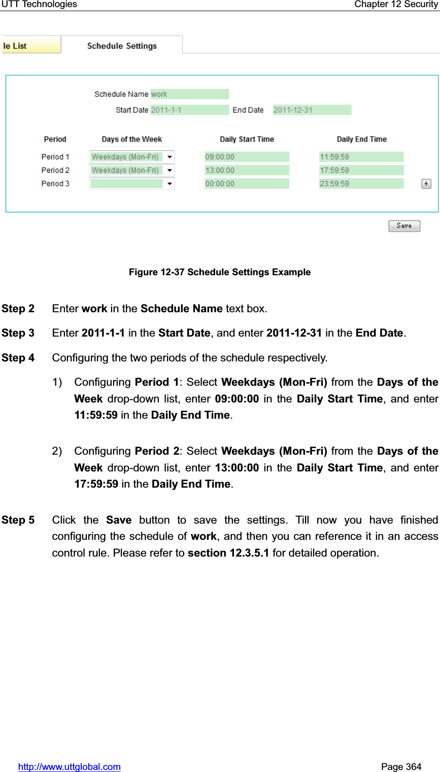
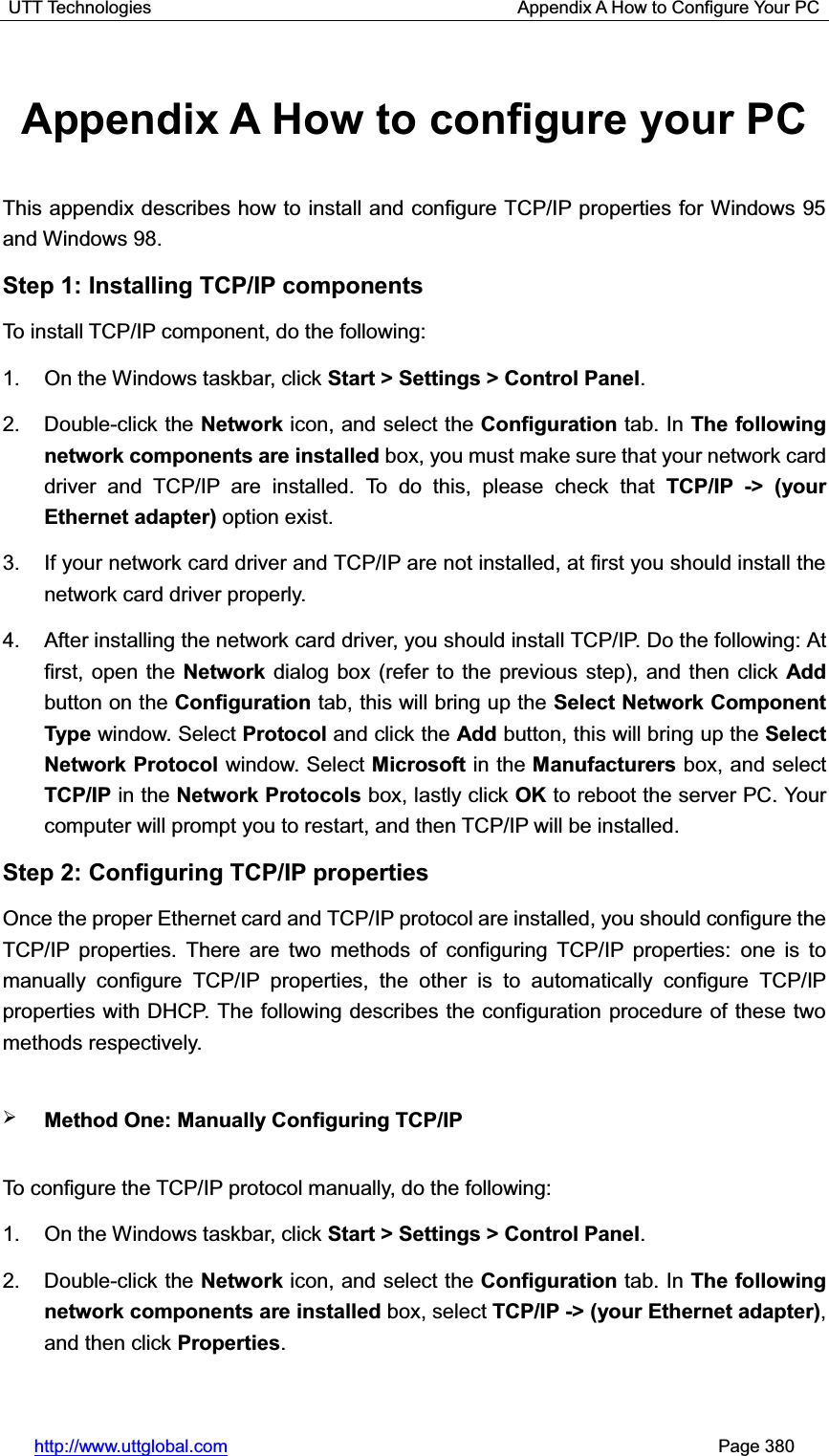
![UTT Technologies Chapter 5 System Statushttp://www.uttglobal.com Page 77 Session up test The Device has successfully established a session whose name is test. Assigned to port @answerIncomingCall:8012 The Device has successfully negotiated with the remote dial-in device, and has assigned a port to the remote device. Call Connected @_netiNetworkStateChanged:6244, on line 1, on channel 0The physical layer and data link layer connections have been established, but IP still couldn¶t be used. Incoming Call @_netiNetworkStateChanged:6187, on line 1, on channel 0 The Device received a call from a remote device. Route Up ethX The static routes bound to the specified physical interface became active. (Usually due to that the corresponding Internet connection became active.) eth1: LAN; eth2~eth5: WAN1~WAN4. Route Down ethX The static routes bound to the specified physical interface became inactive. ˄Usually due to that the corresponding Internet connection became inactive.˅NAT exceeded [IP Address]The specified host has exceeded the maximum NAT sessions limited by the Device. Usually due to that this host is infected with a virus or it is using hacker attack software. If the host is working properly, please increase the maximum NAT sessions appropriately. ARP exceeded [IP Address]The APR request for the specified IP address has been rejected due to the maximum ARP entries limit. If the ARP table is full, any new ARP request packet to the Device will be rejected and this log message generated.](https://usermanual.wiki/UTT-TECHNOLOGIES/REG01-UTT/User-Guide-1659606-Page-92.png)
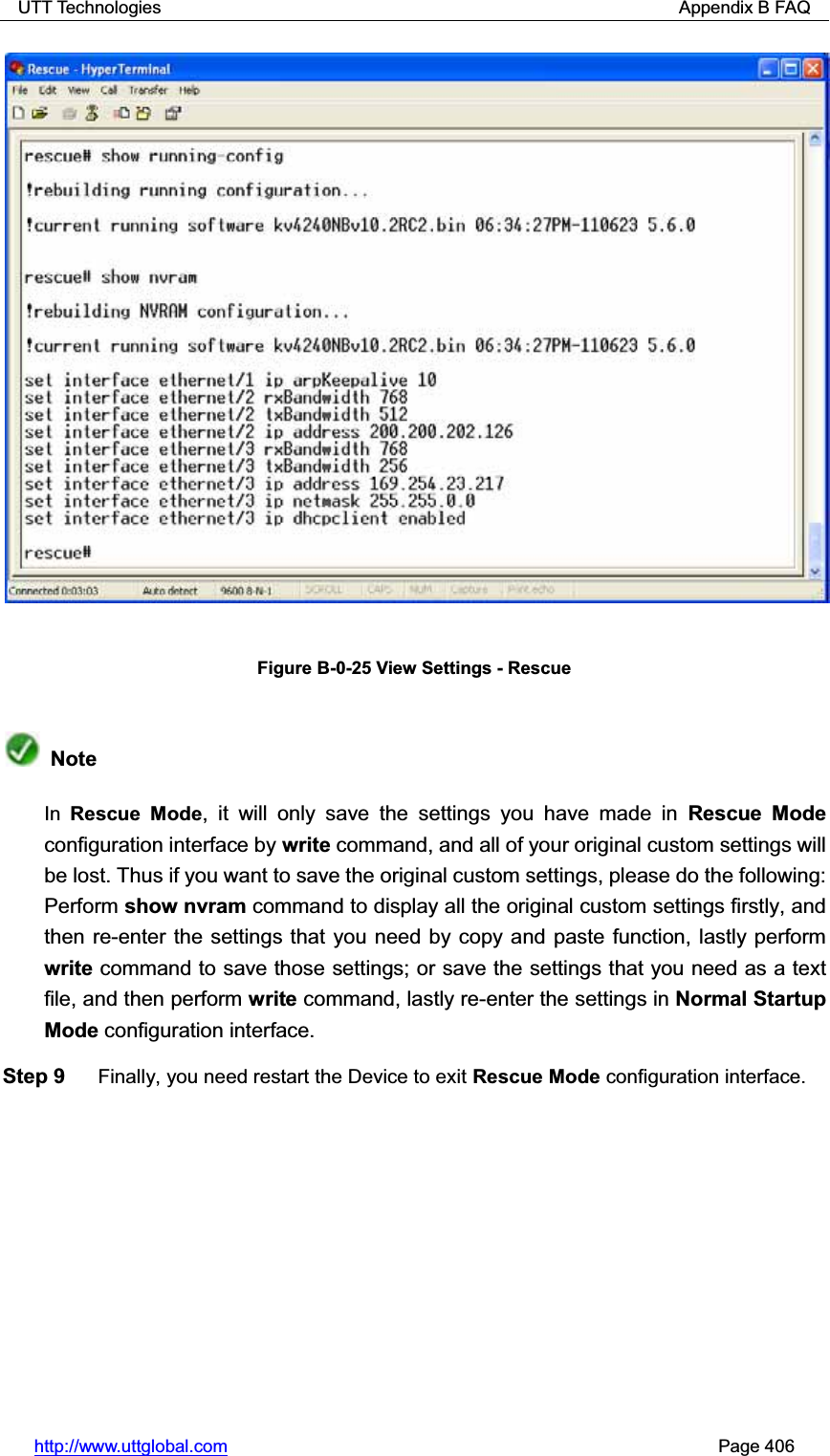
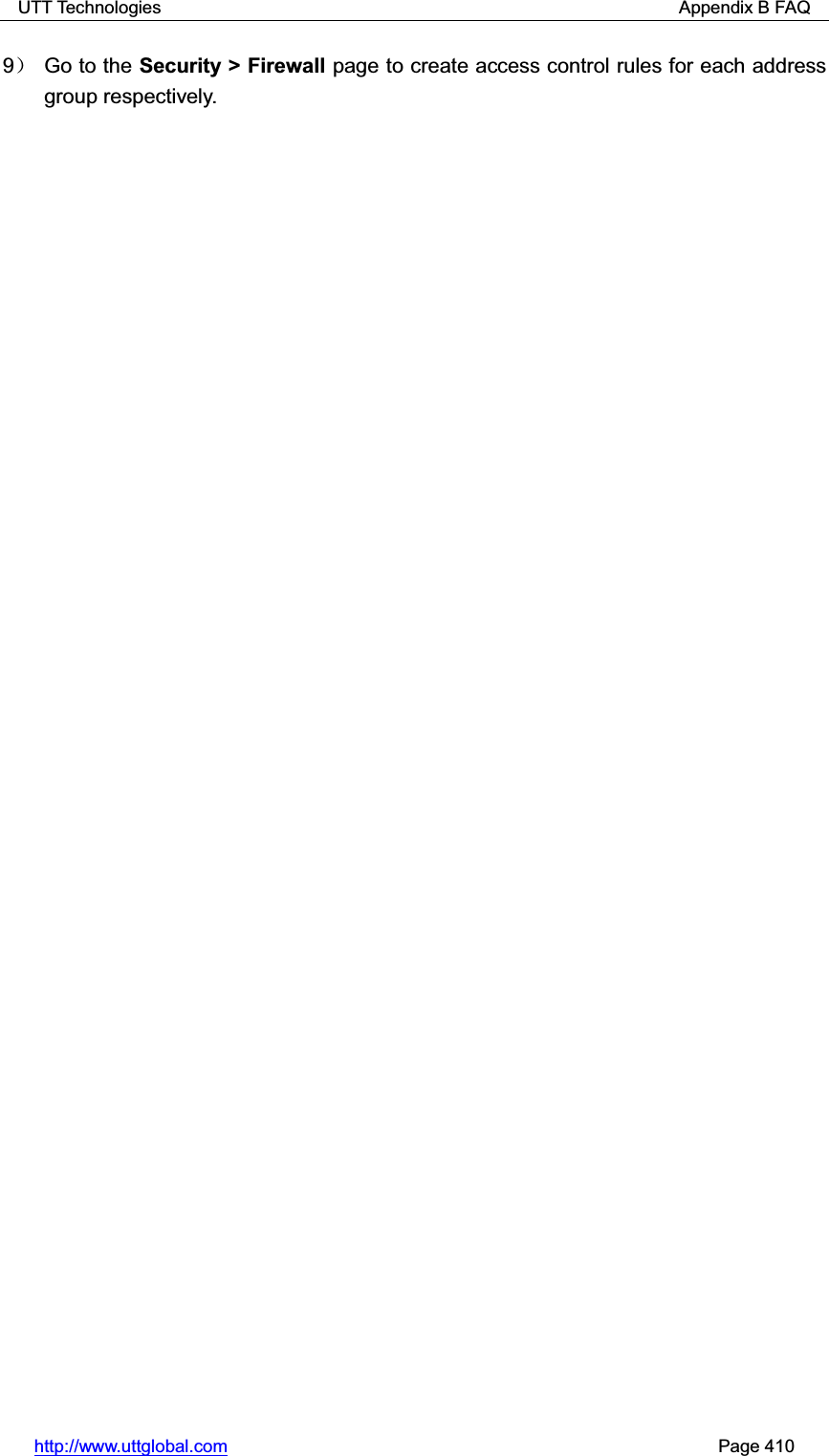
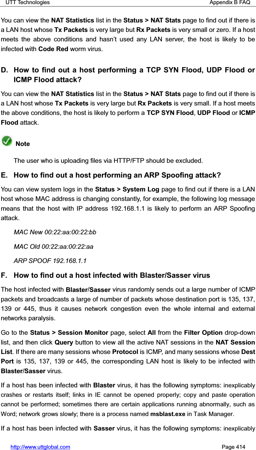
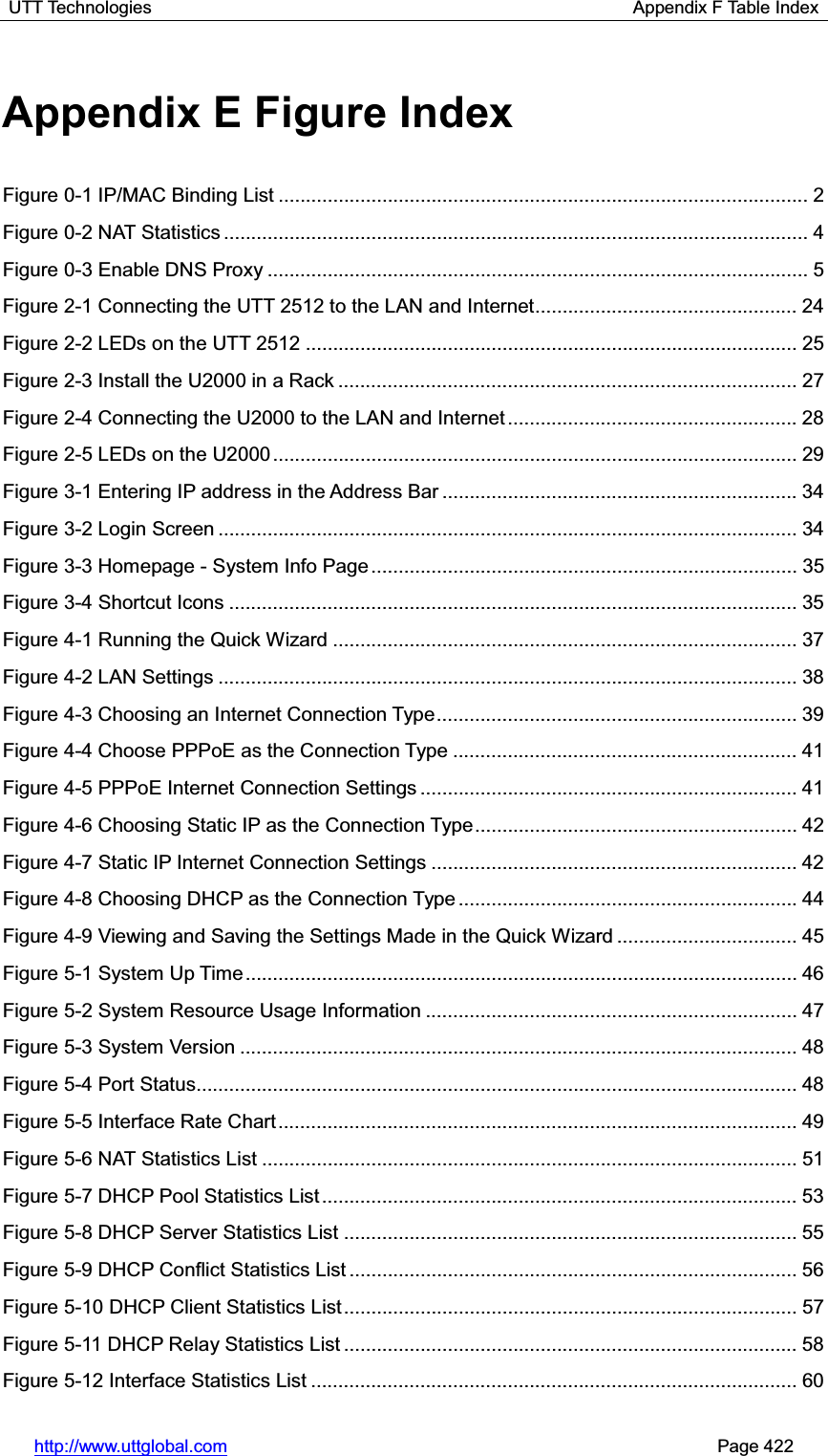
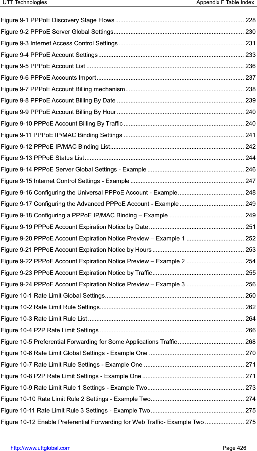
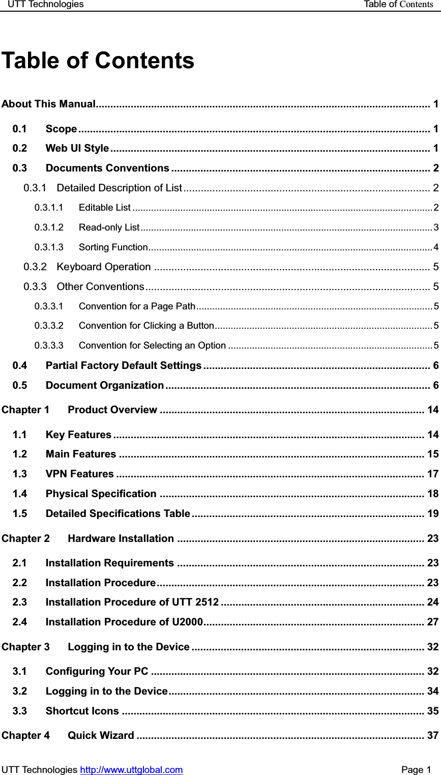
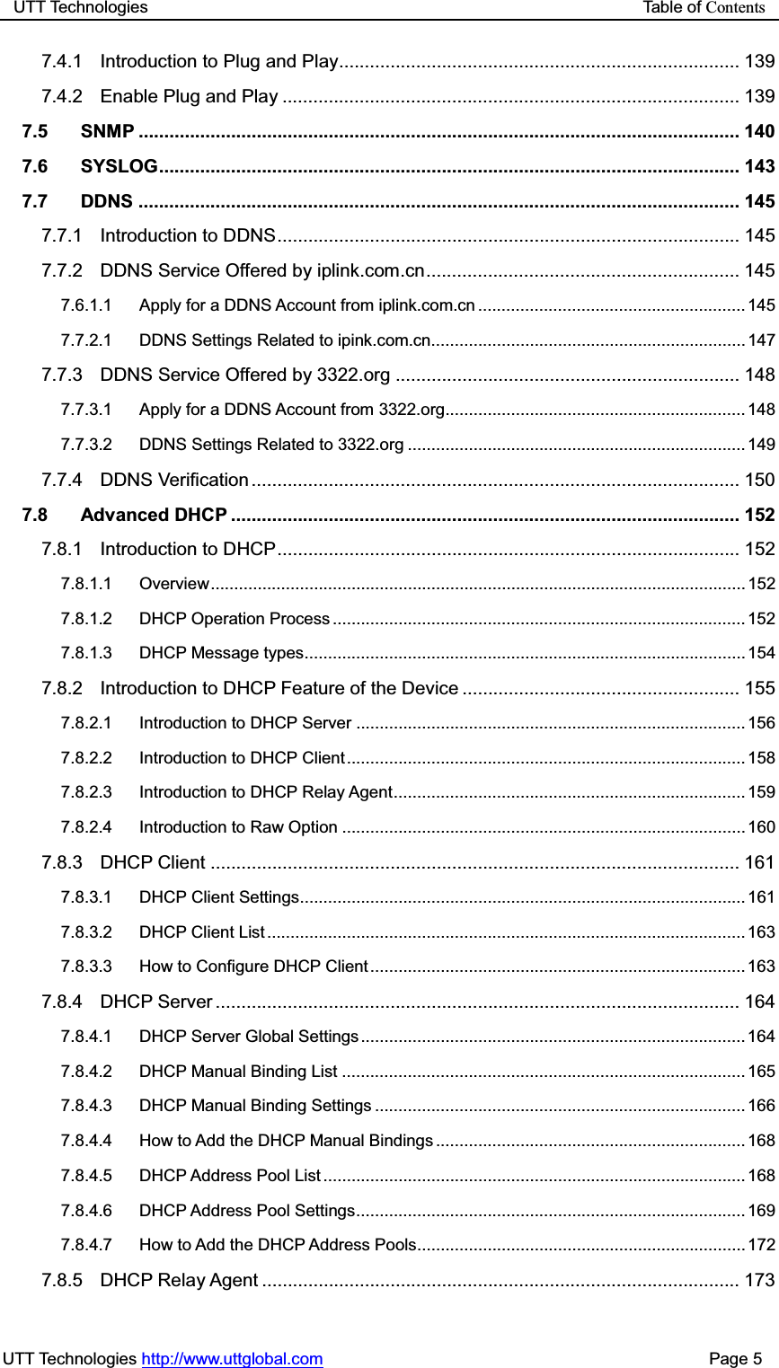
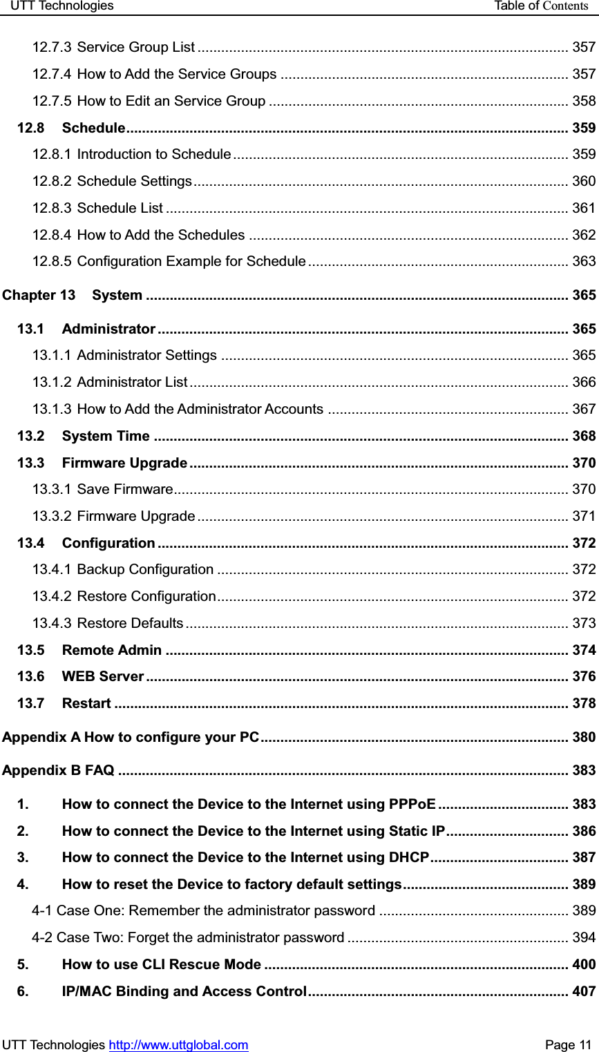
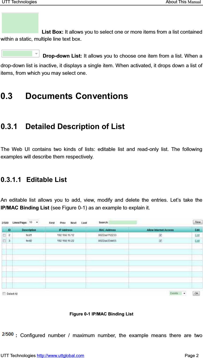
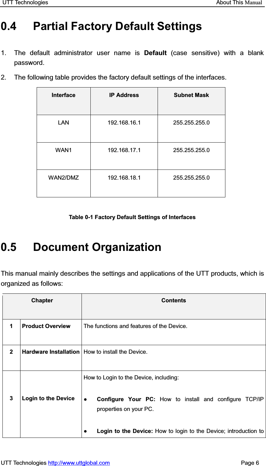
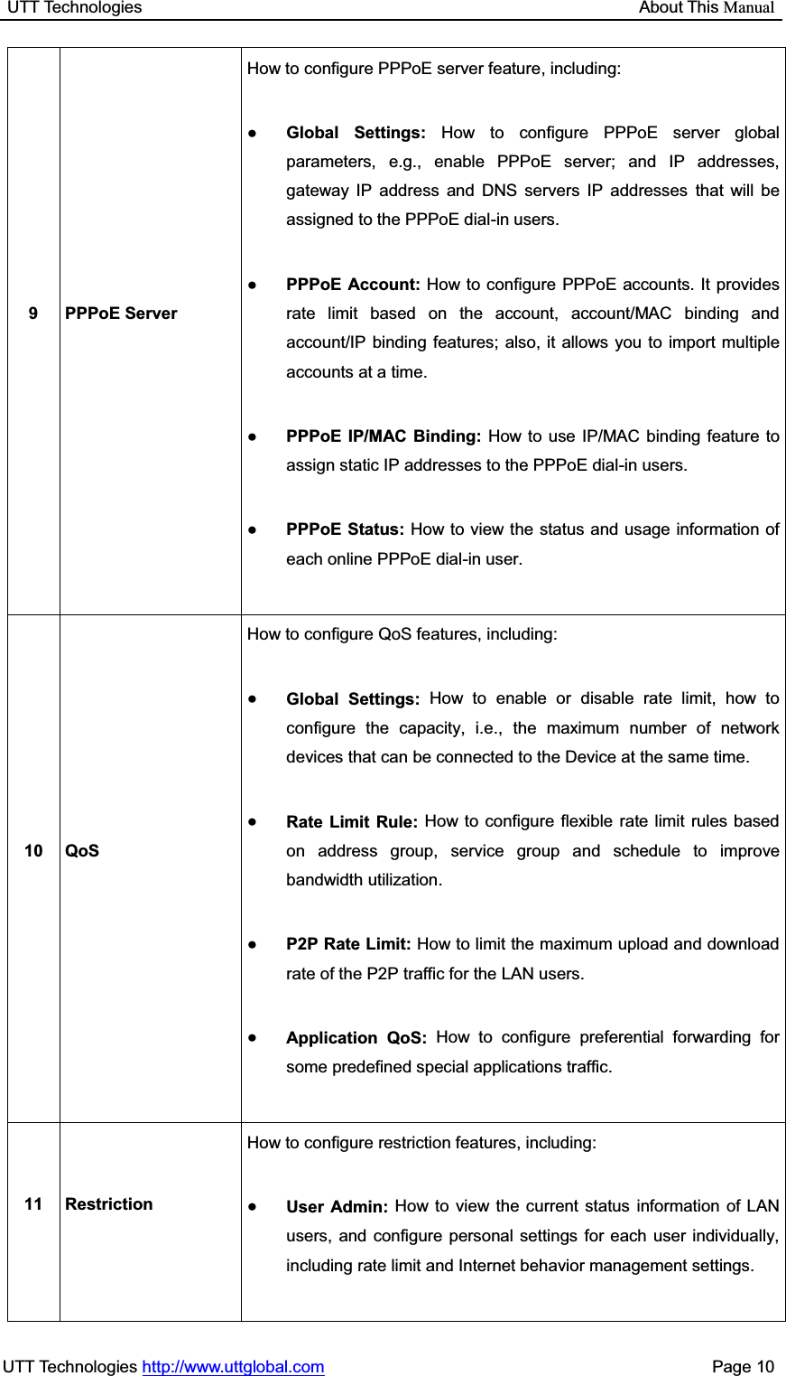
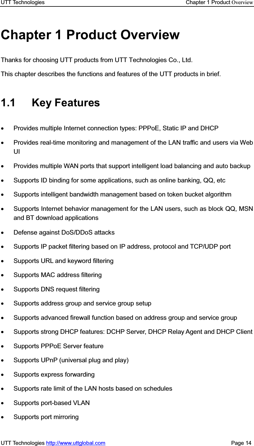
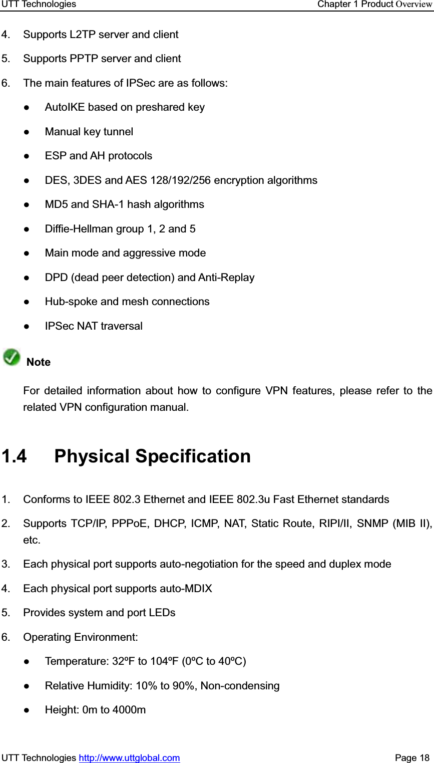
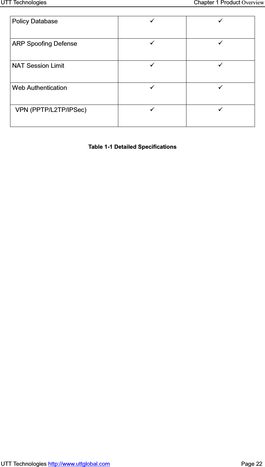
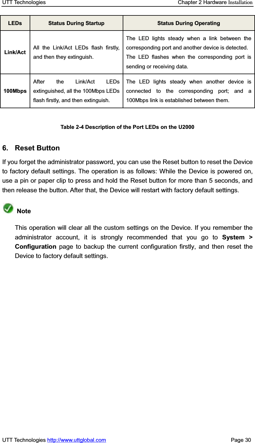
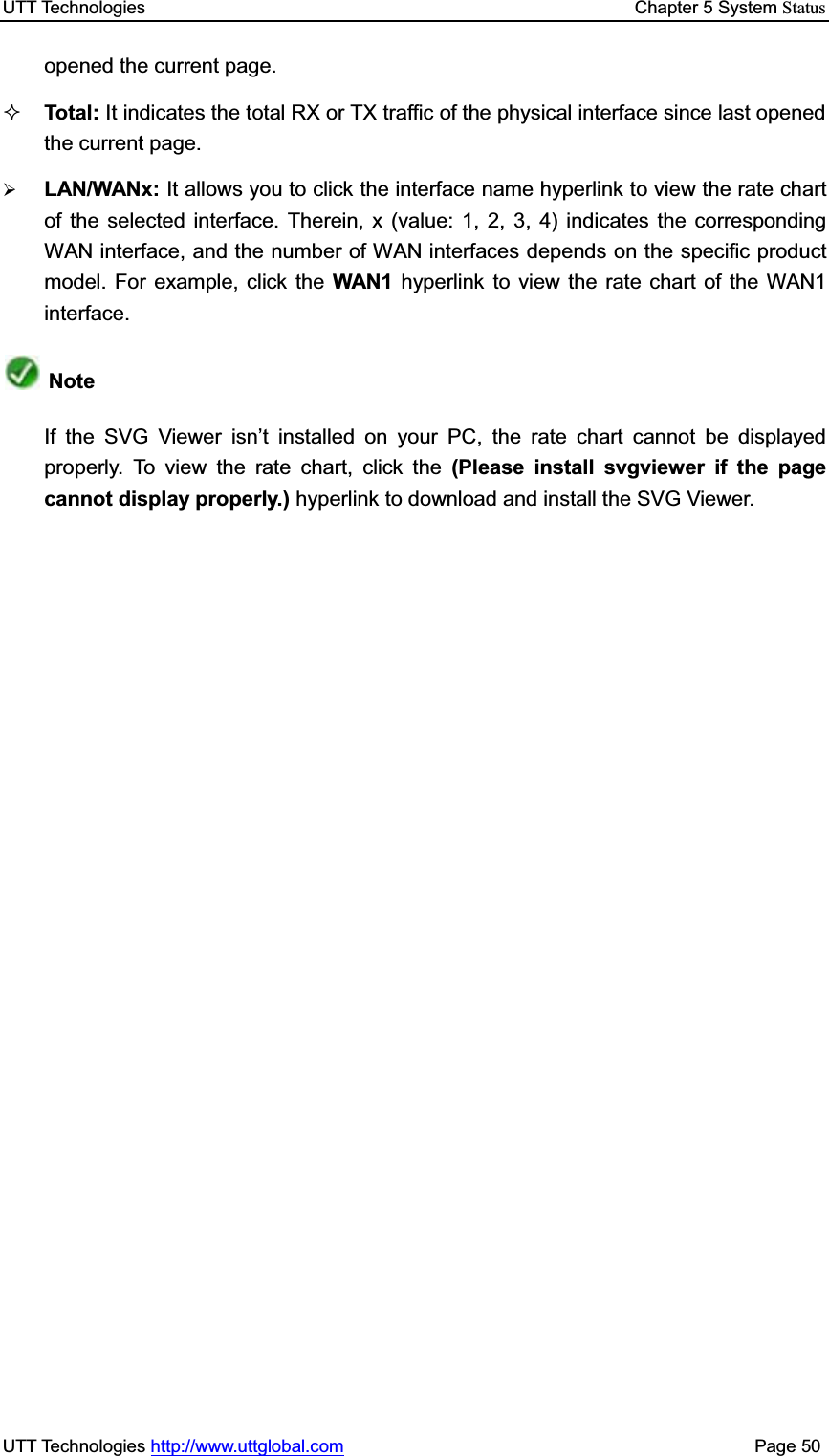
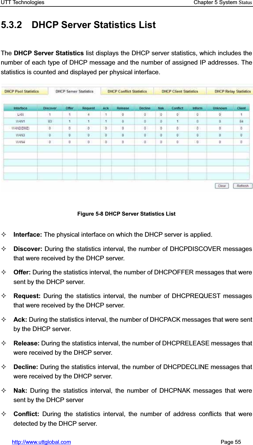
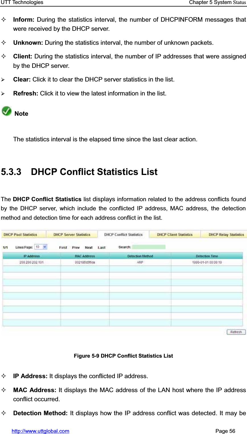
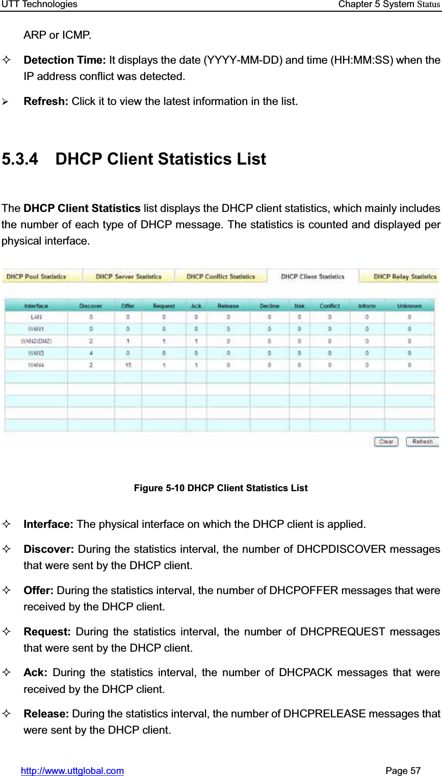
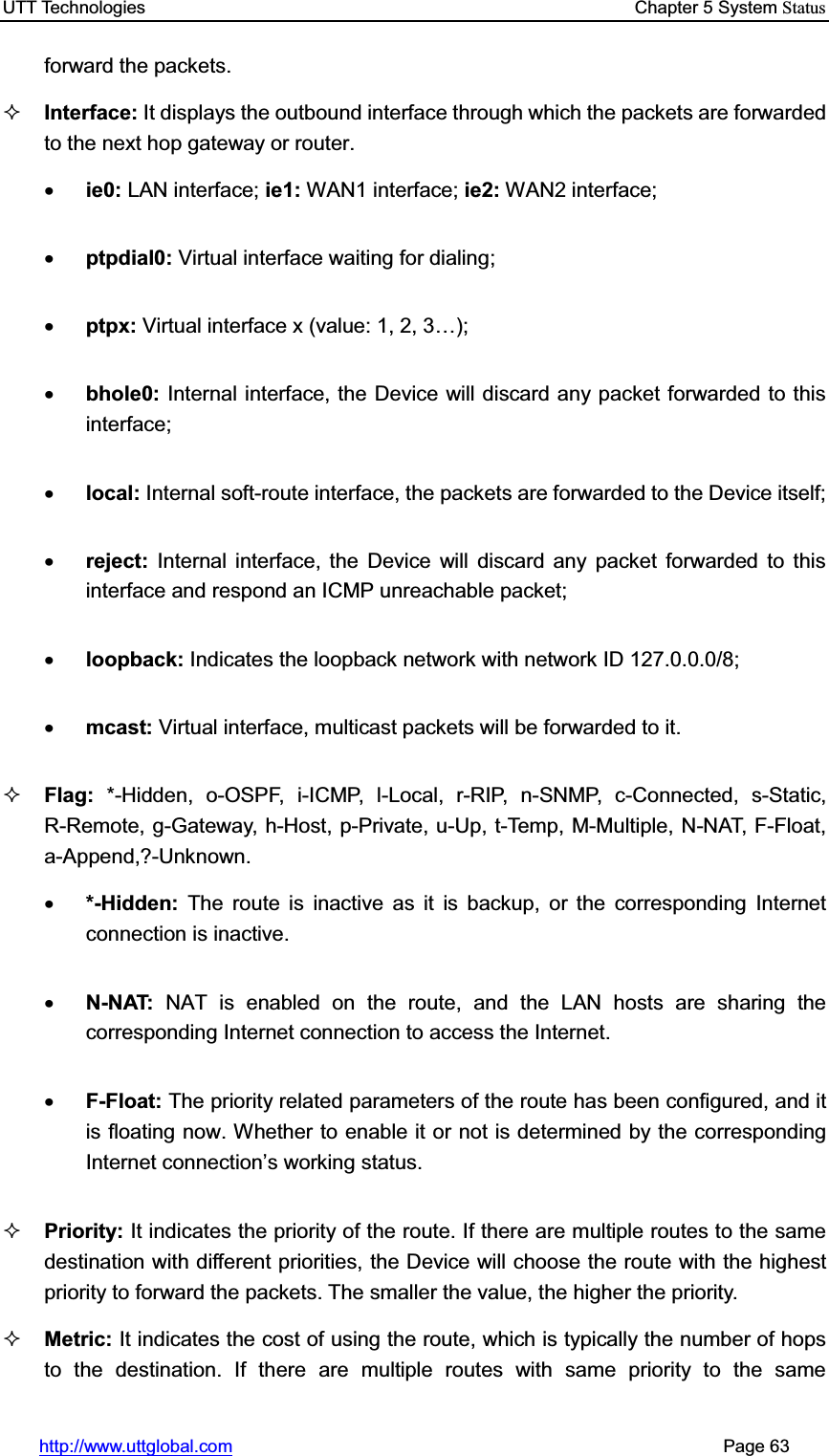
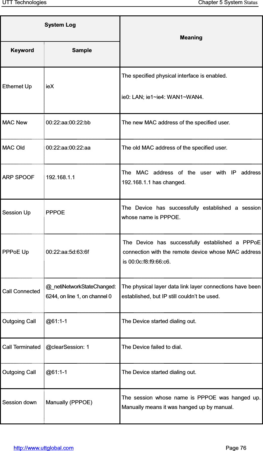
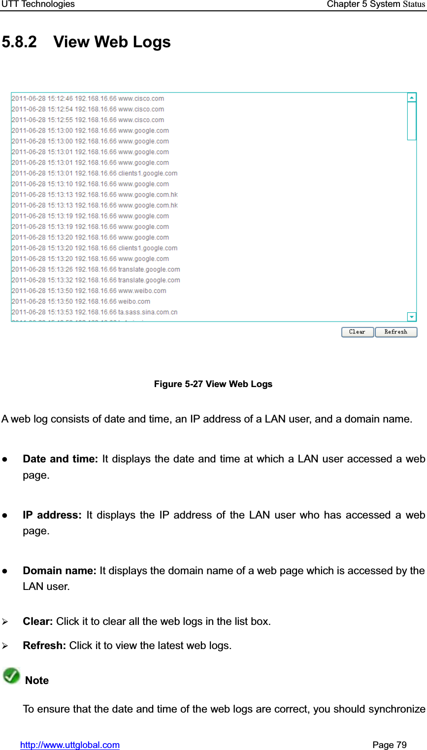
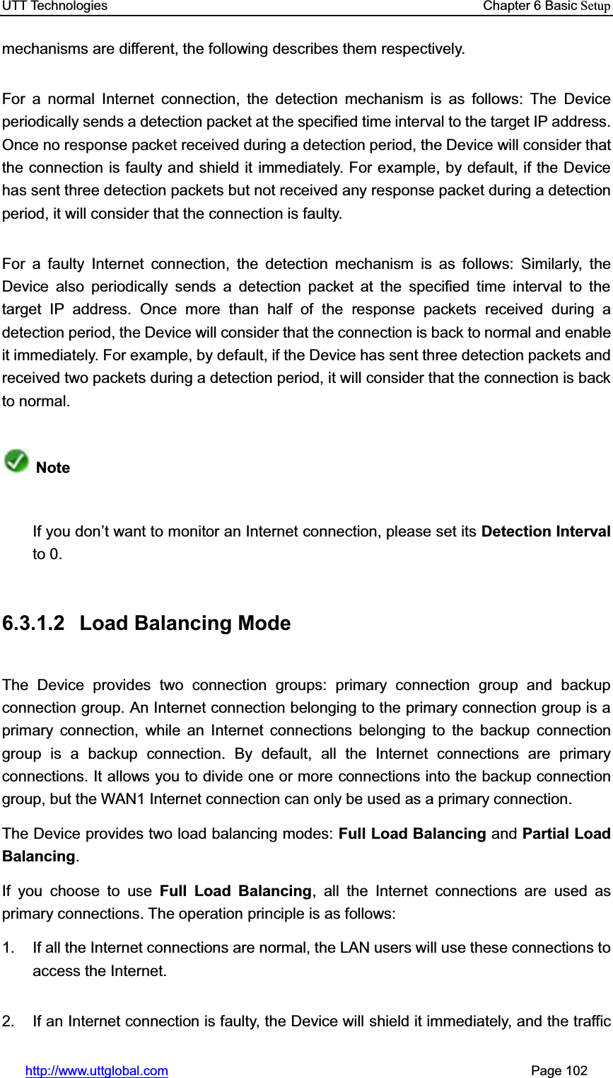
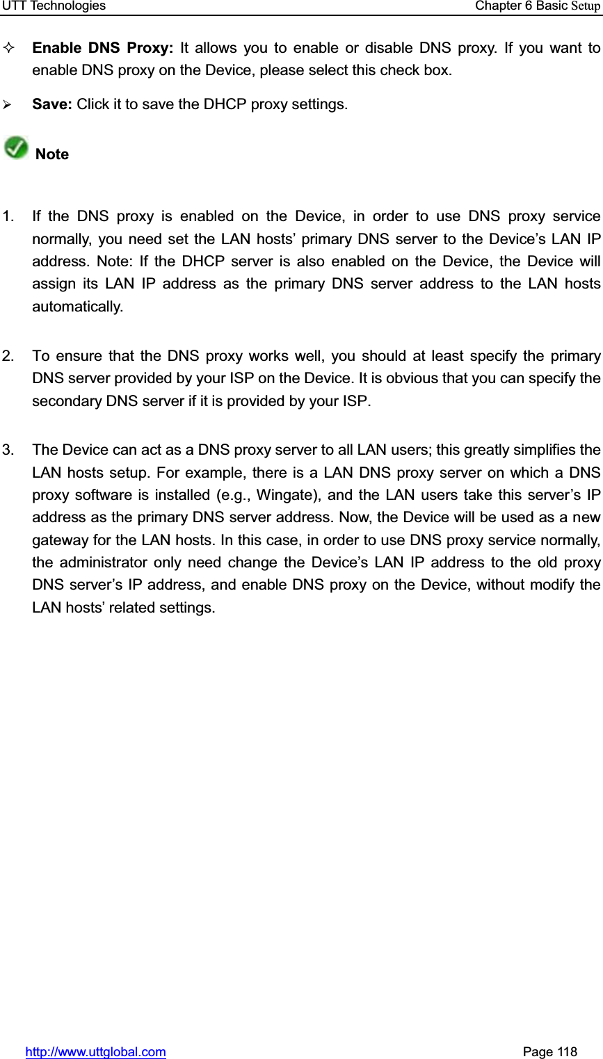
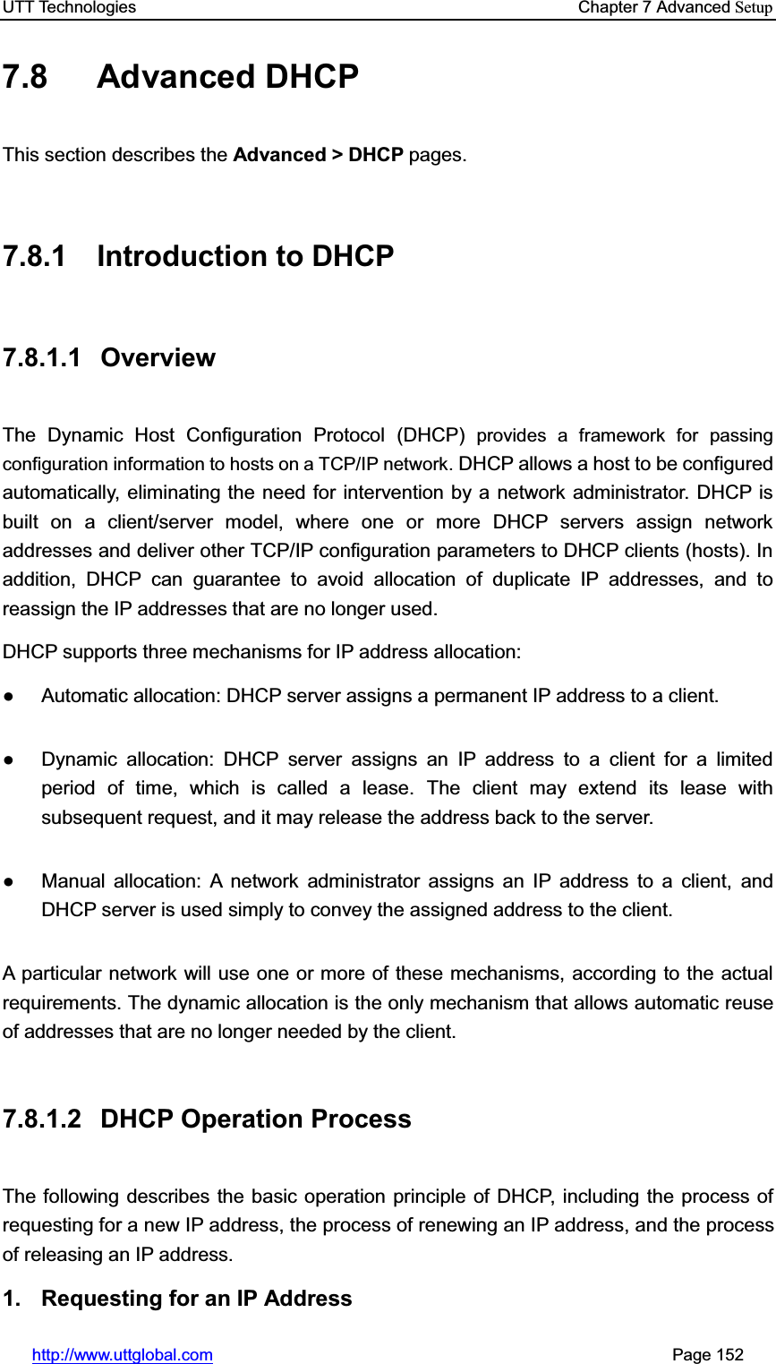
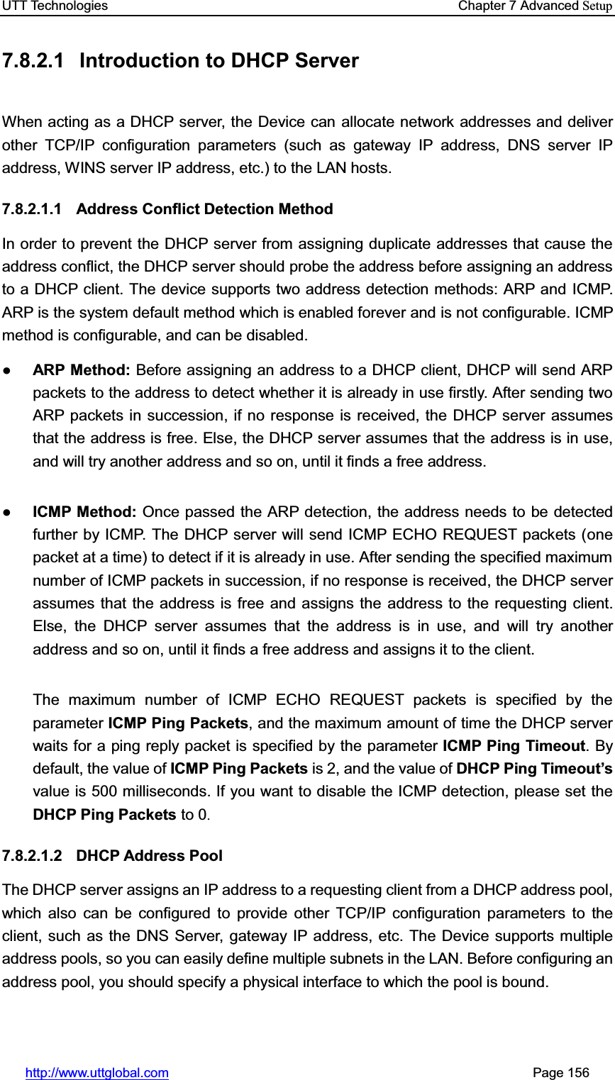
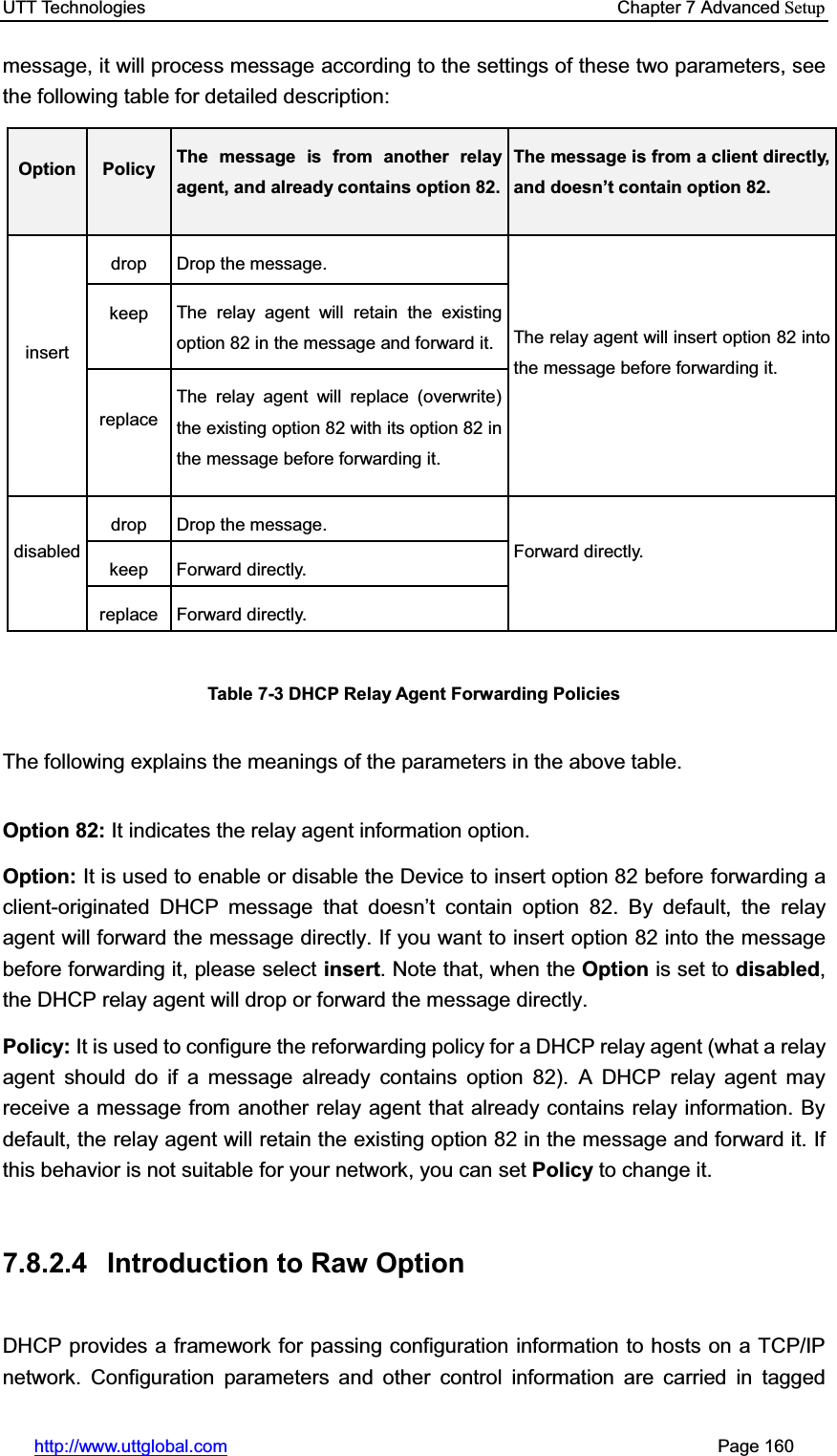
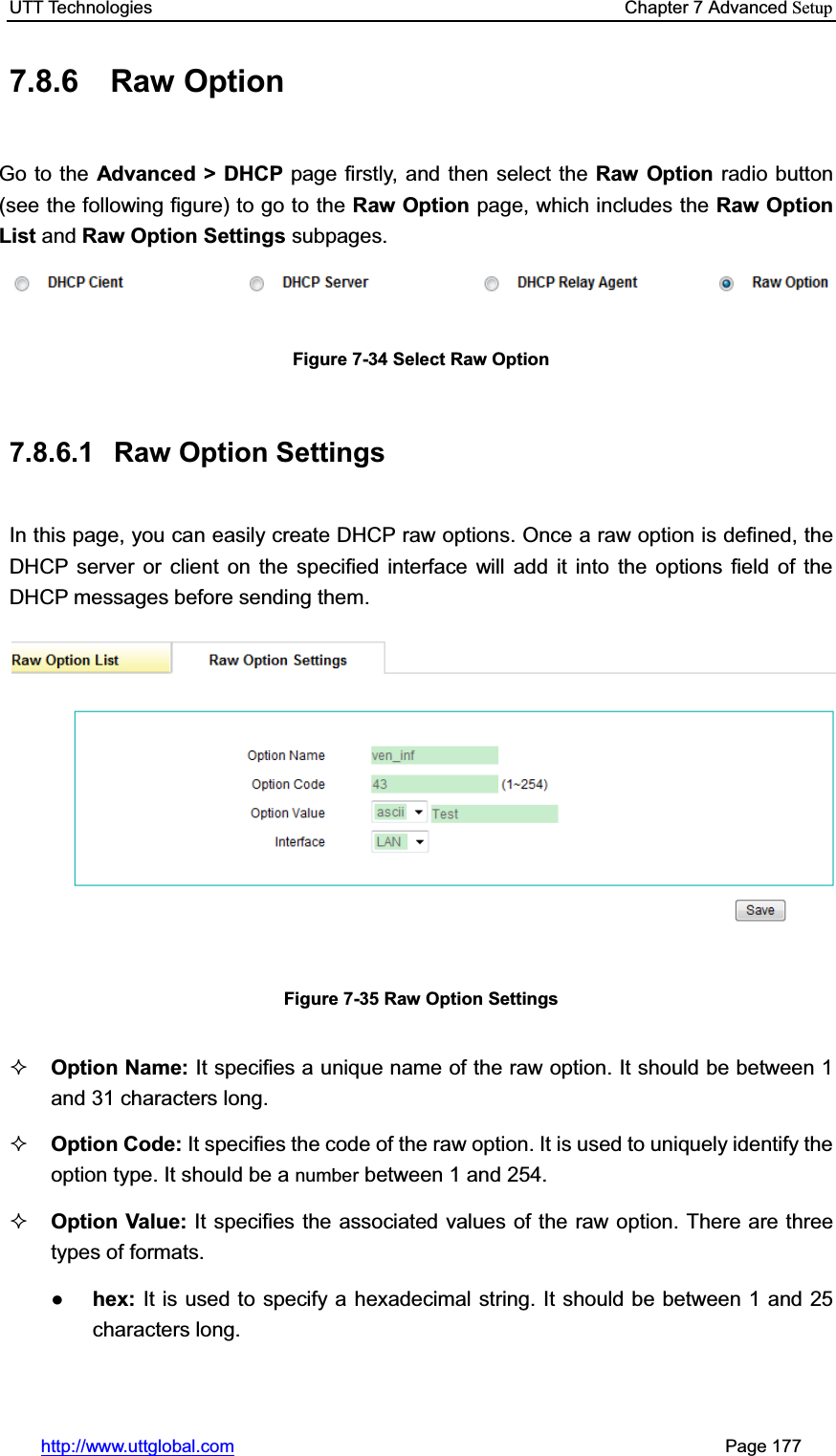
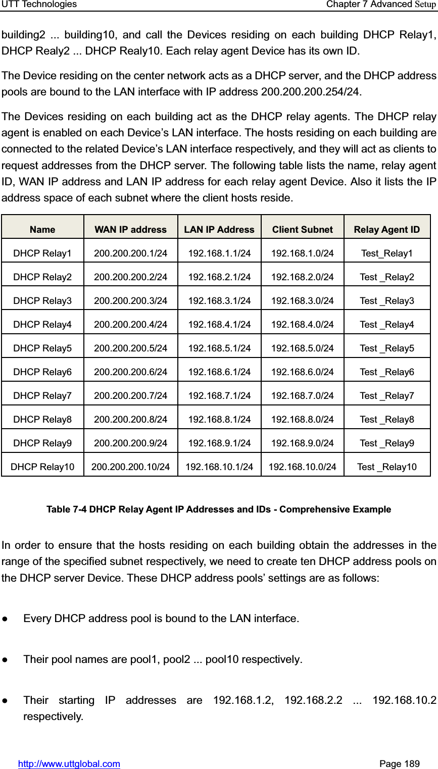
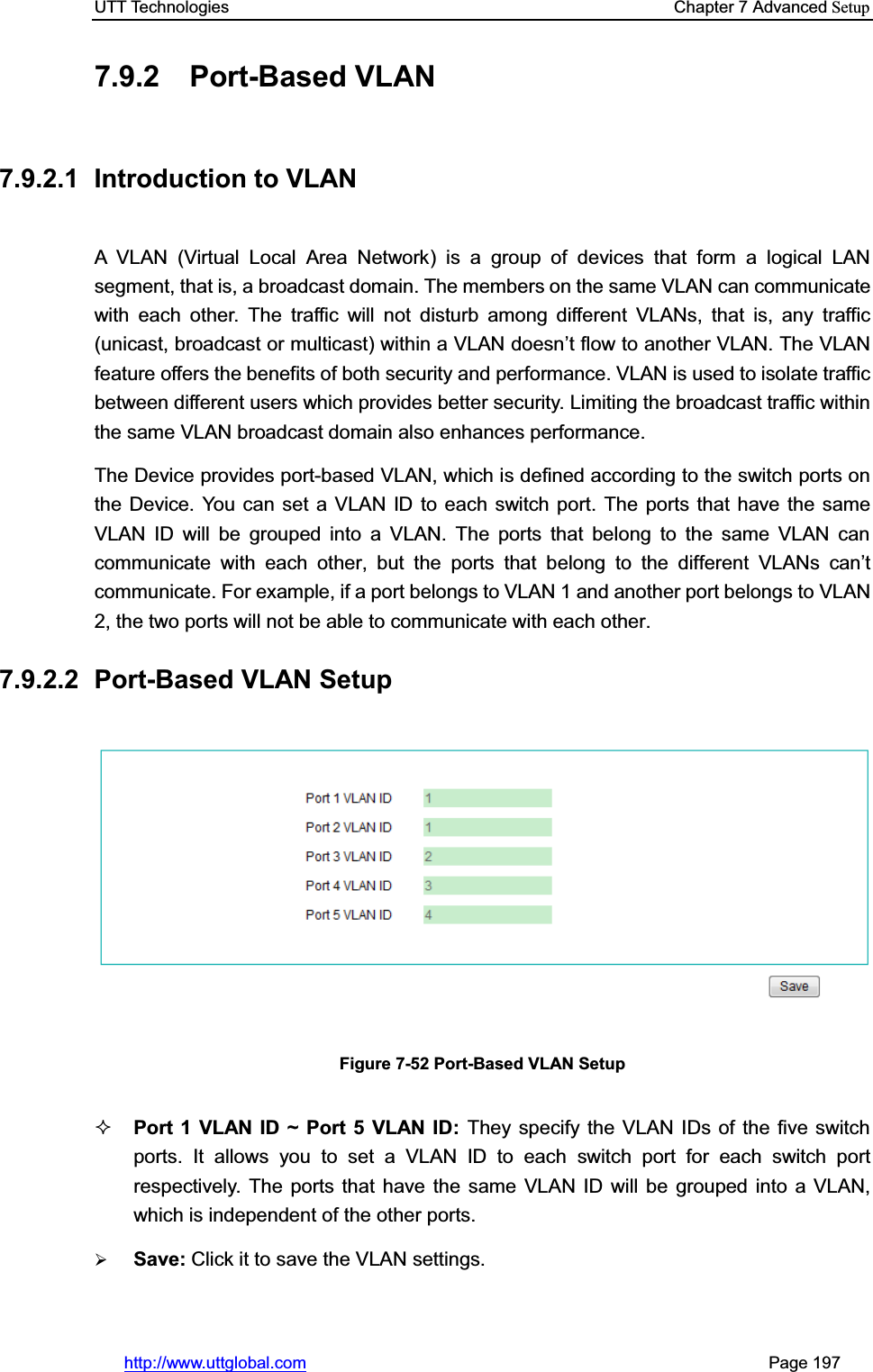
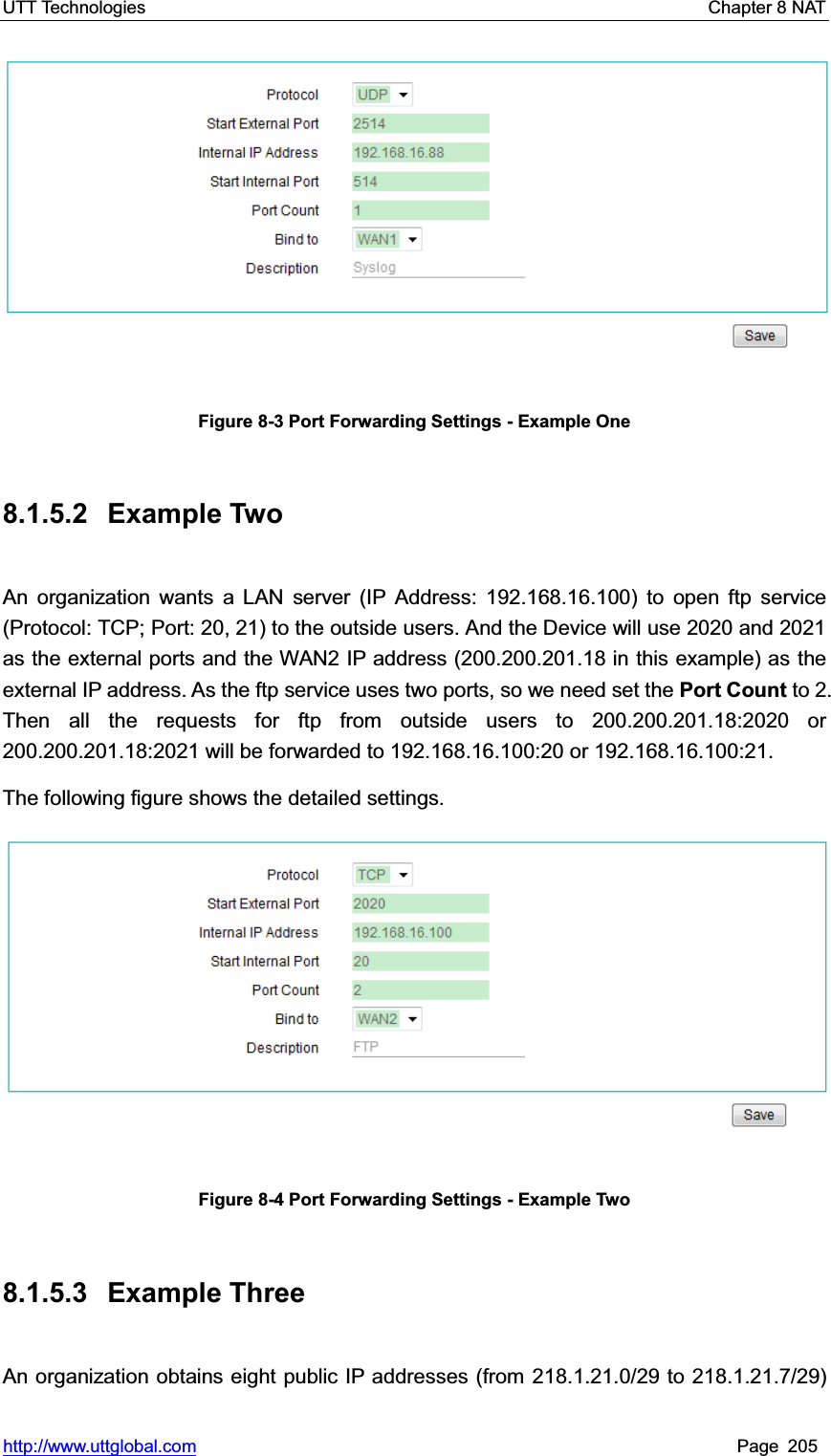
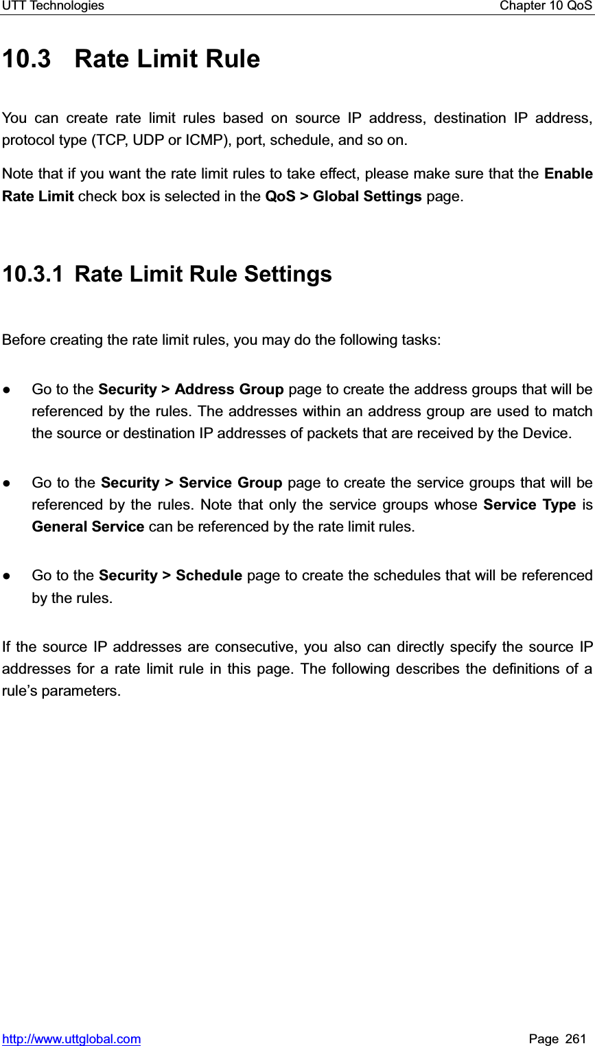
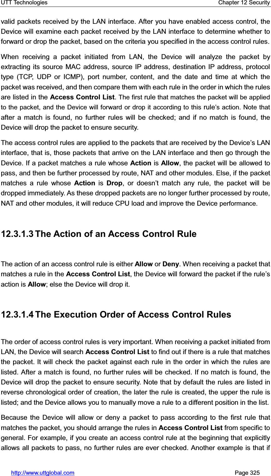
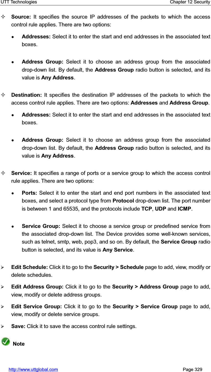
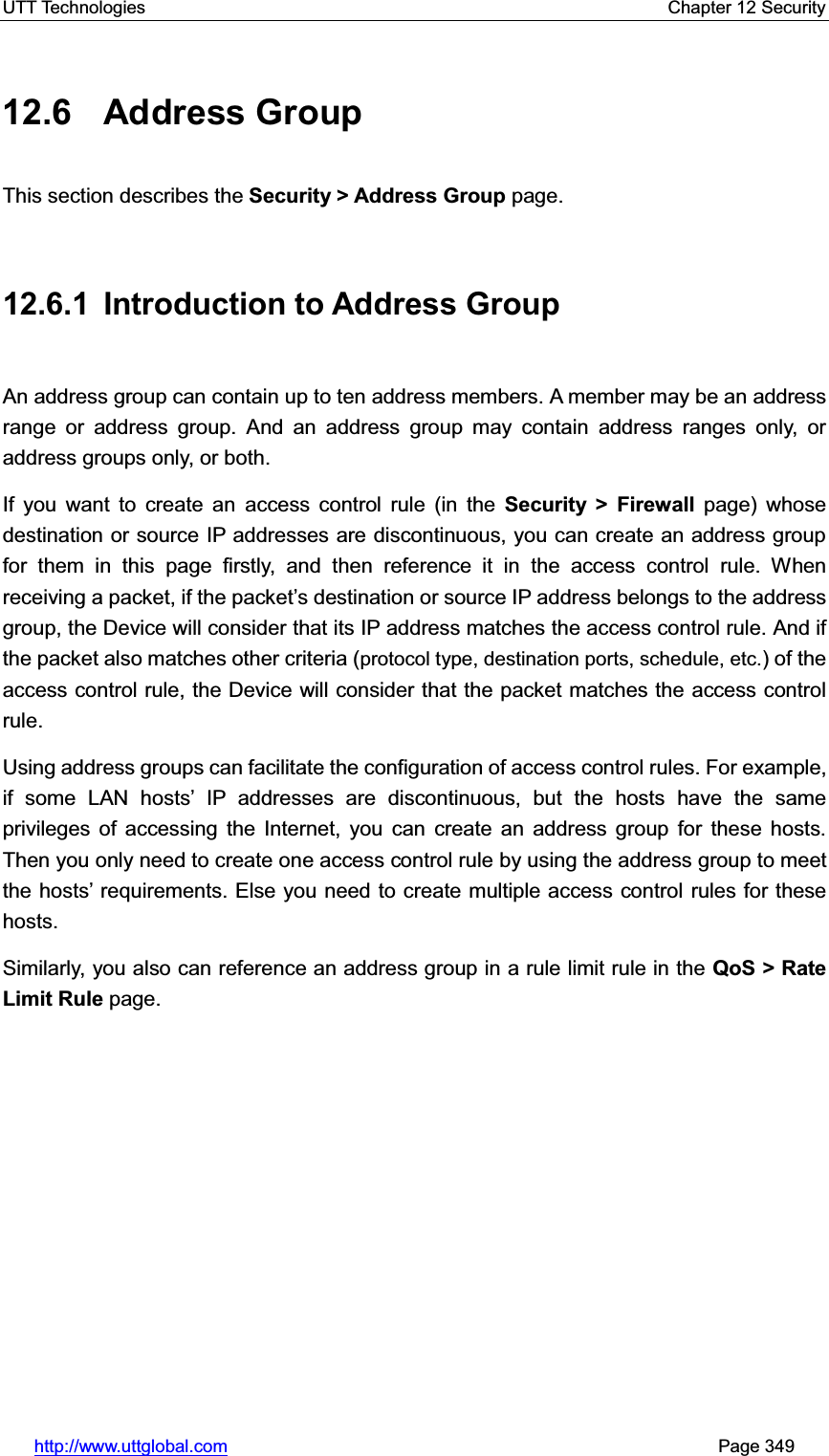
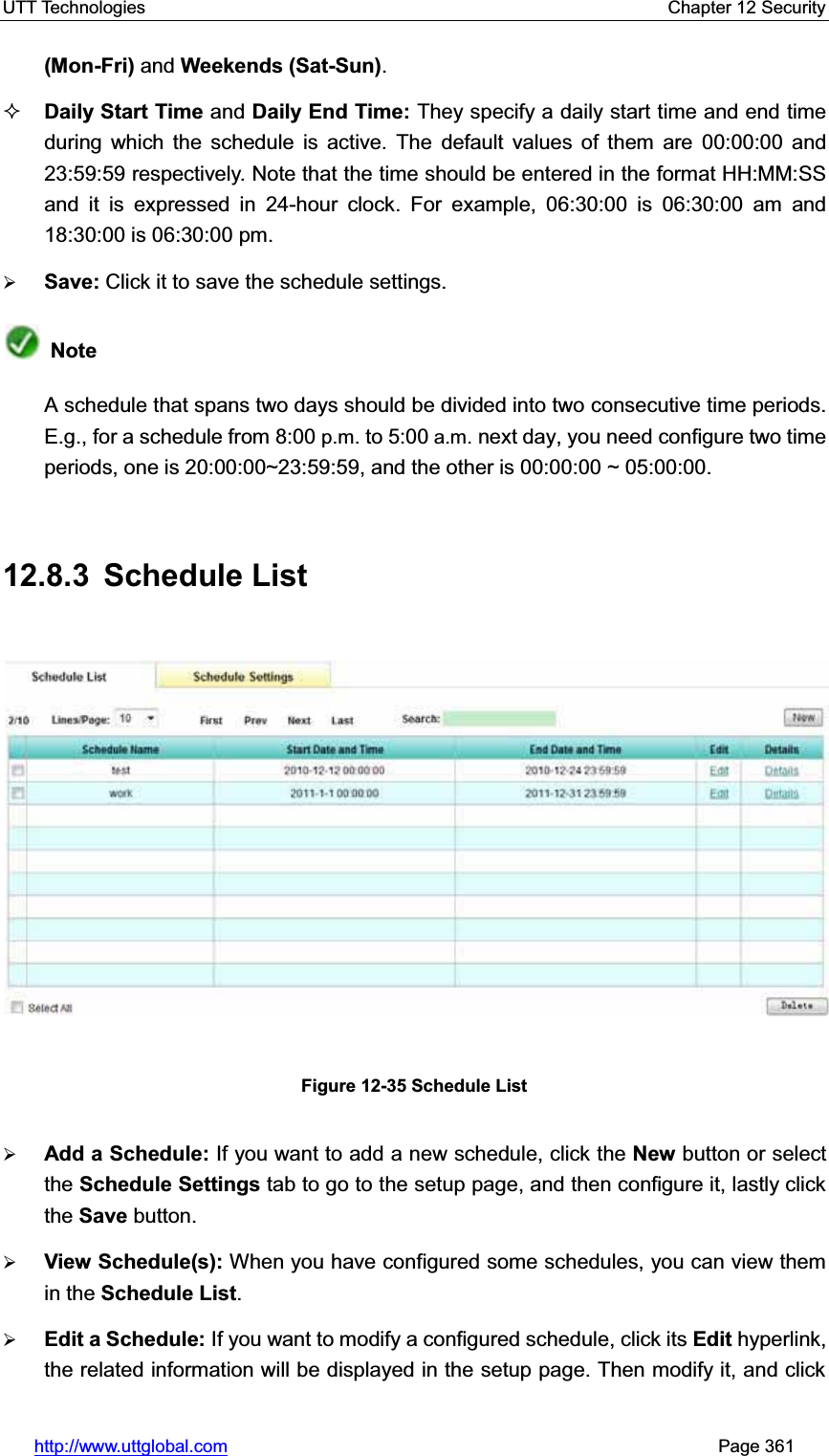
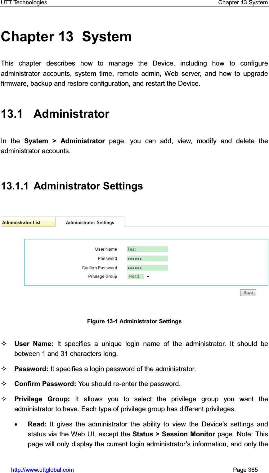
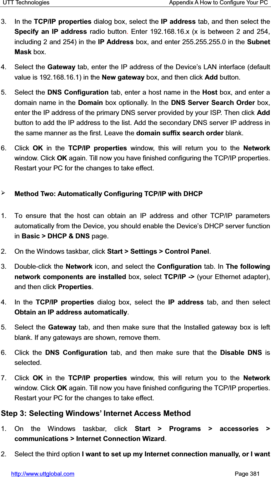
![UTT Technologies Chapter 5 System Statushttp://www.uttglobal.com Page 78 DHCP:IP conflicted [arp: IP Address]A DHCP IP address conflict has occurred, that is, when acting as a DHCP server, the Device detected that the specified IP address is already used in the LAN before assigning it to a user, and then the Device assigned another IP address to this user. notice Give notice to user: 192.168.16.35 The device has given a notice to the user with IP address 192.168.16.35. Table 5-1 System Logs List 5.8 Web Log This section describes the Status > Web Log page. In this page, it allows you to view web logs. A web log records the information of a web page access by a LAN user, which include: the access time, the LAN user¶s IP address, and the domain name of the web page. 5.8.1 Enable Web Log Figure 5-26 Enable Web Log Enable Web Log: It allows you to enable or disable web log. If you want the Device to store and display the web logs in this page, please select this check box. ¾Save: Click it to save your settings.](https://usermanual.wiki/UTT-TECHNOLOGIES/REG01-UTT/User-Guide-1659606-Page-93.png)
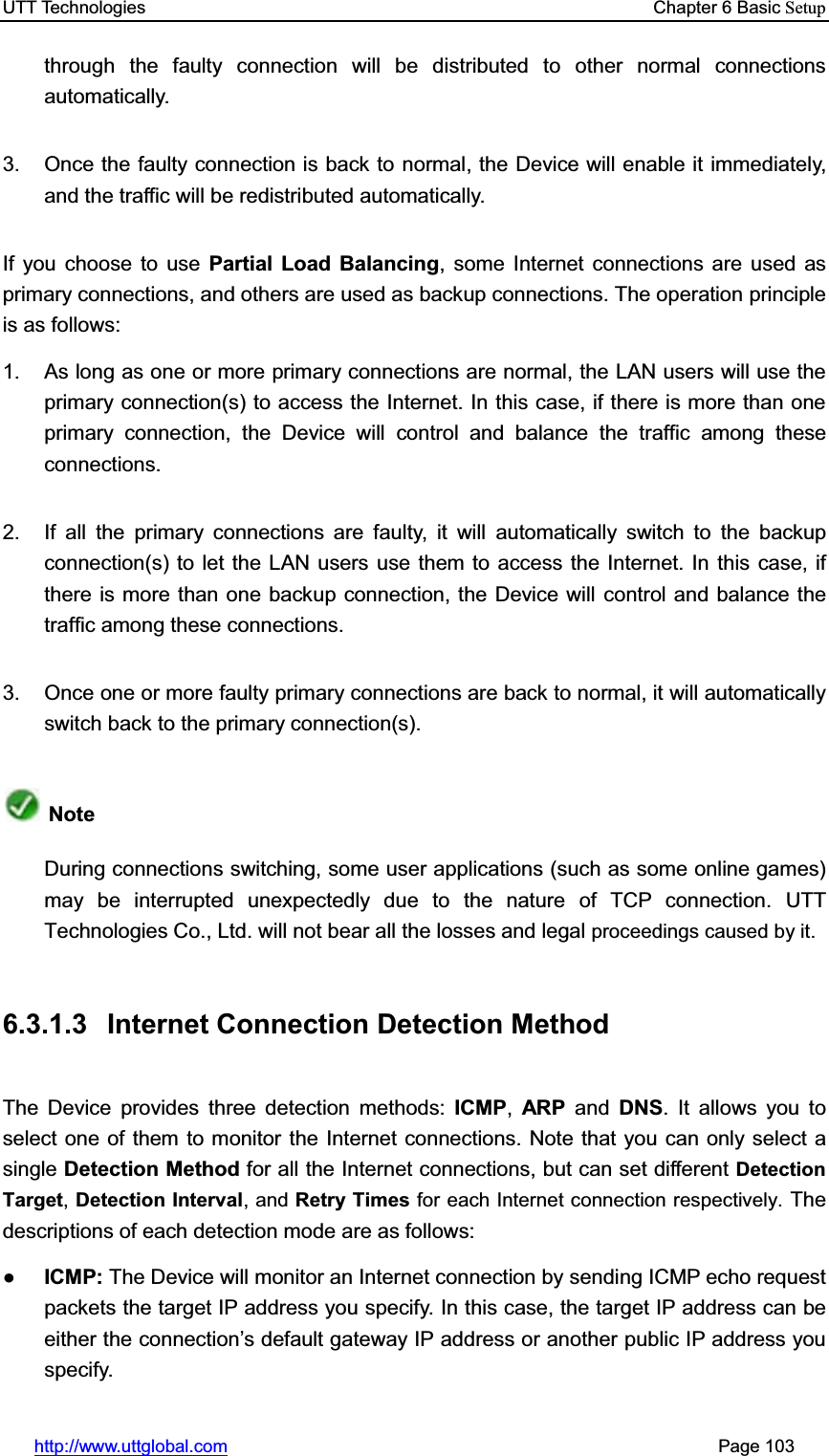
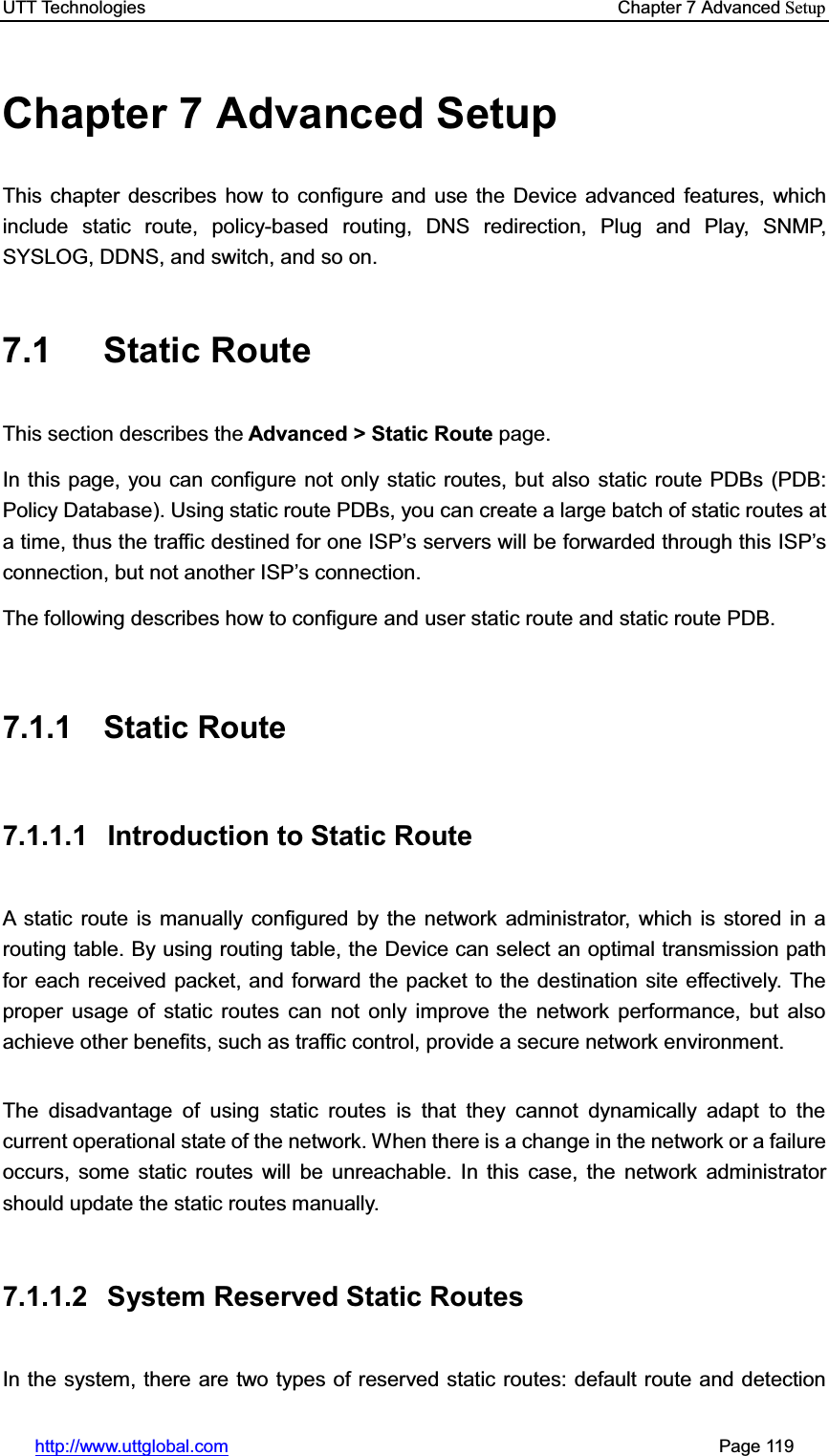


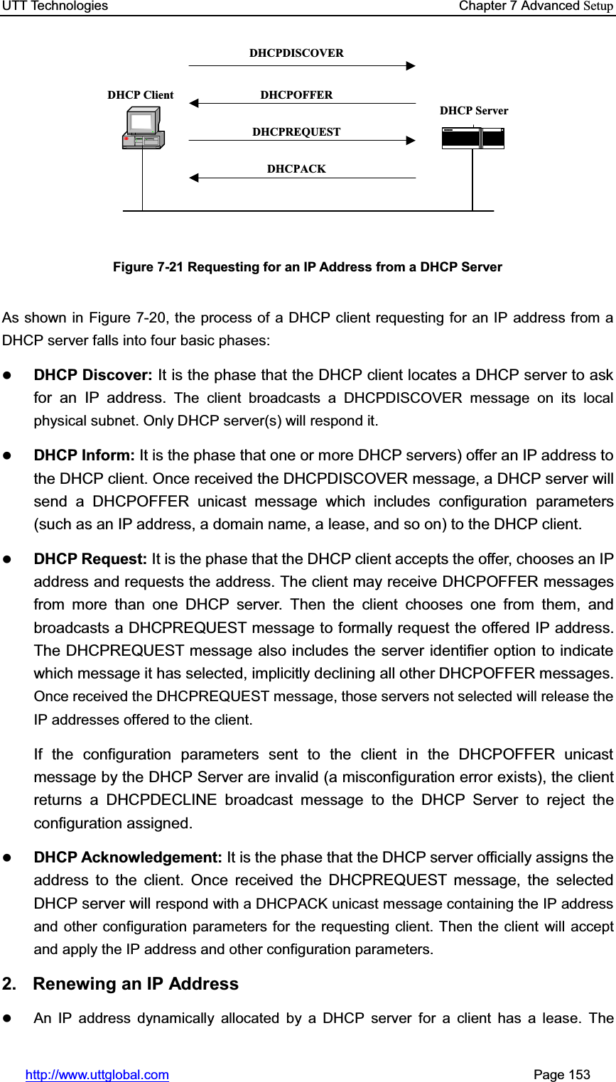
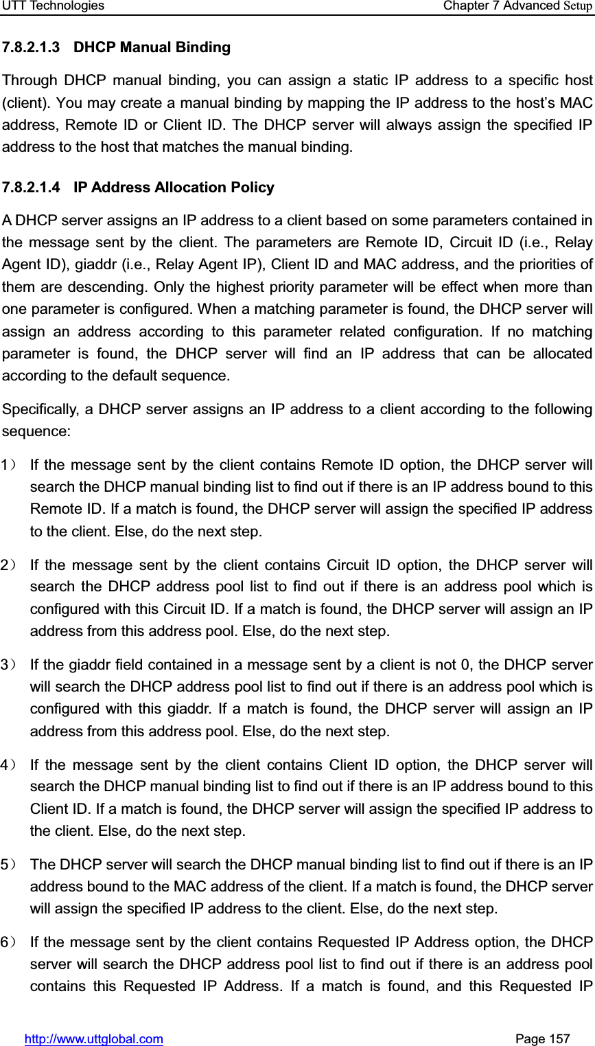
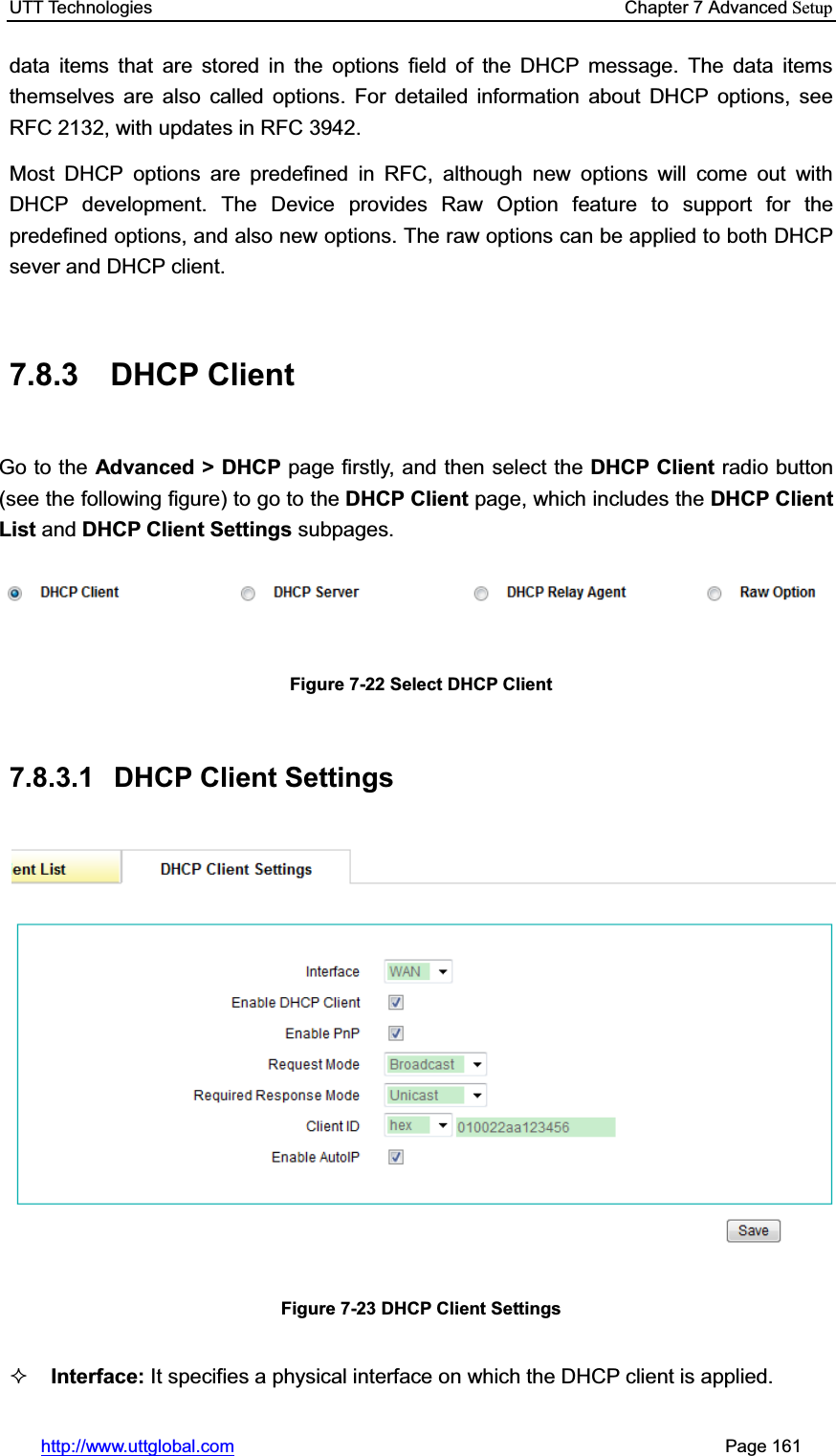

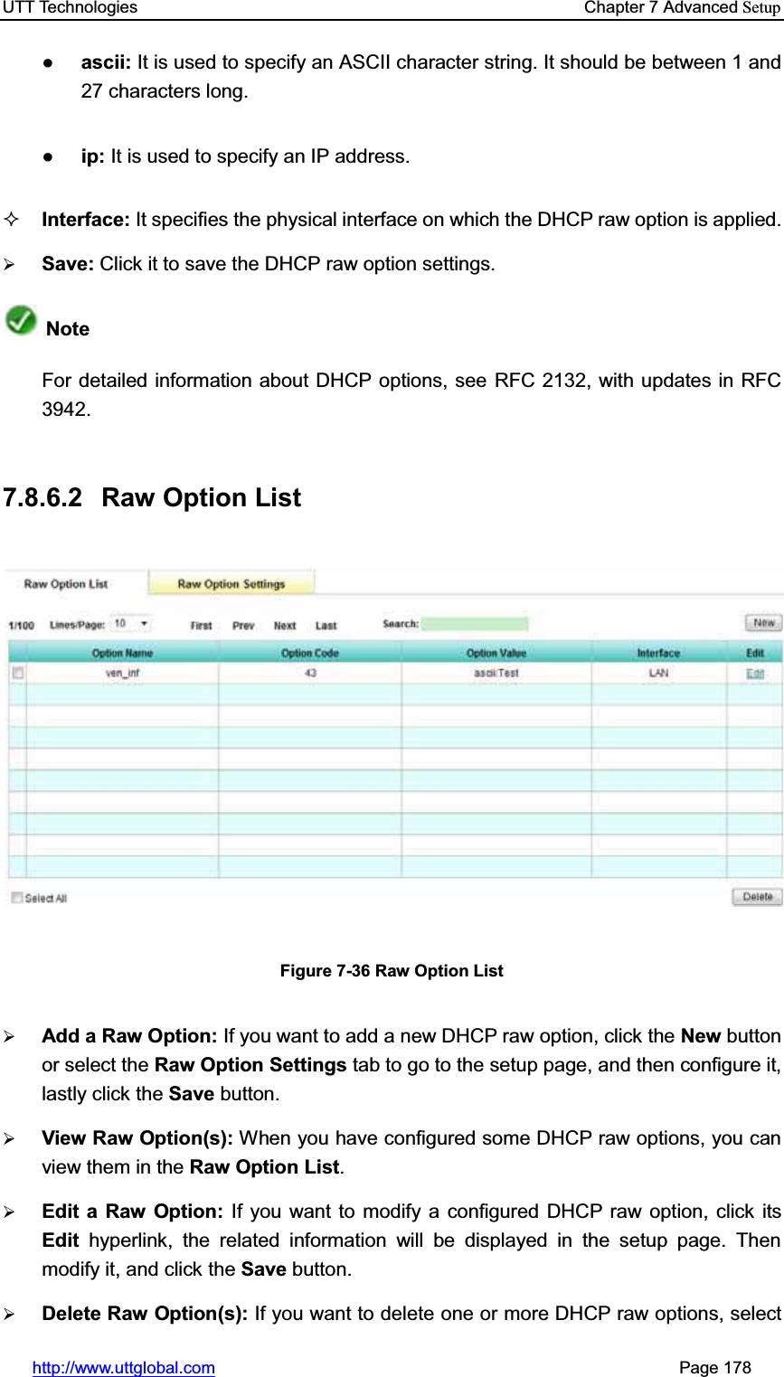
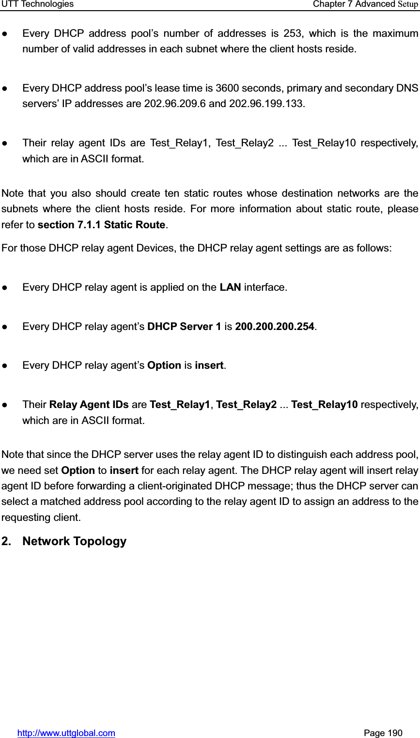
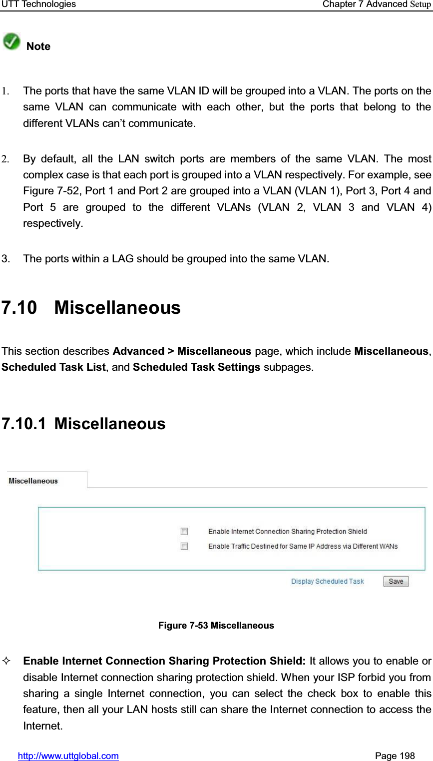
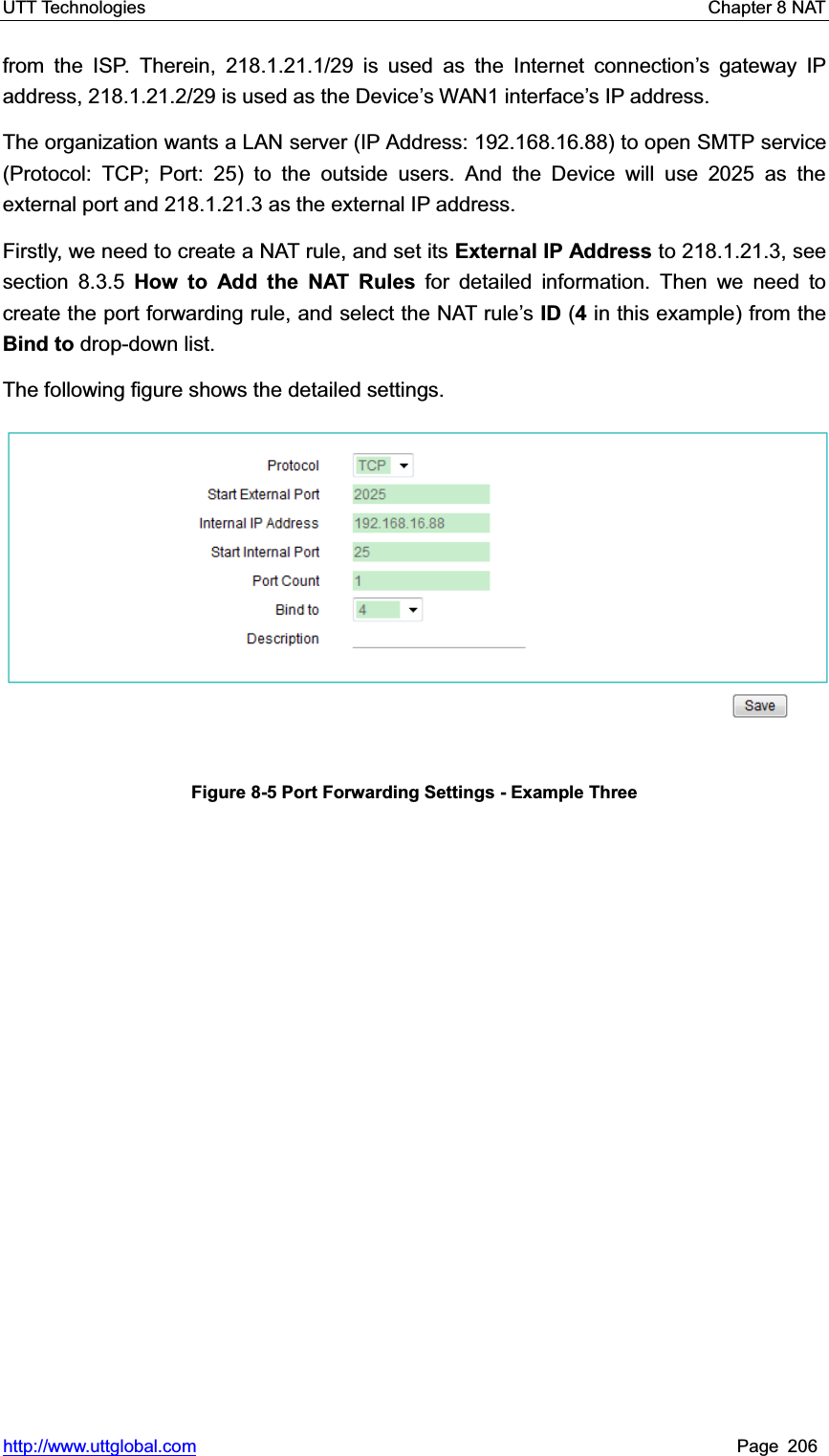
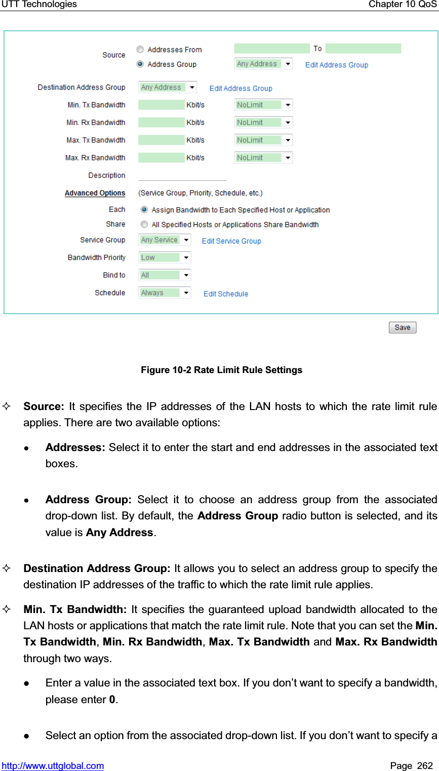
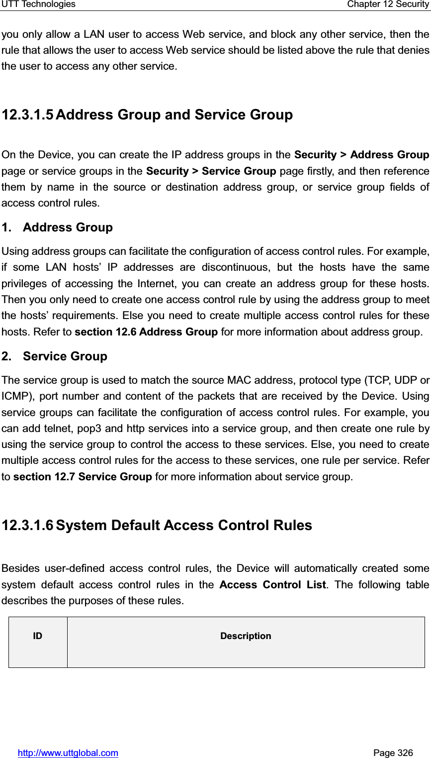
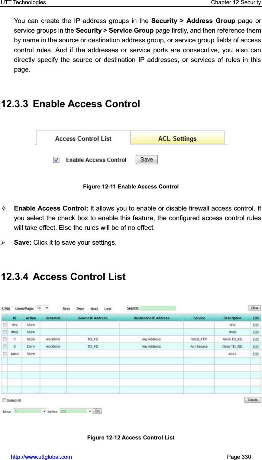
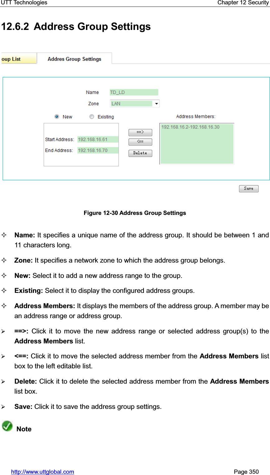
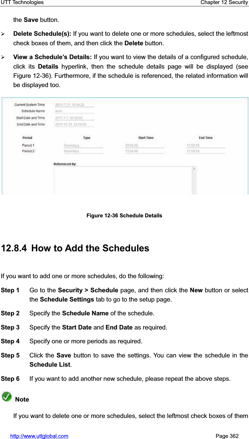
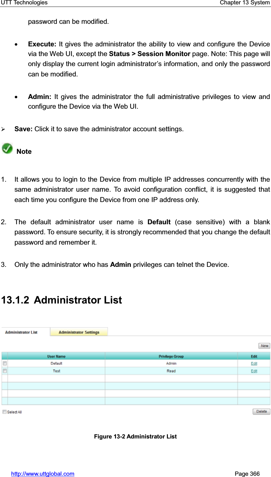
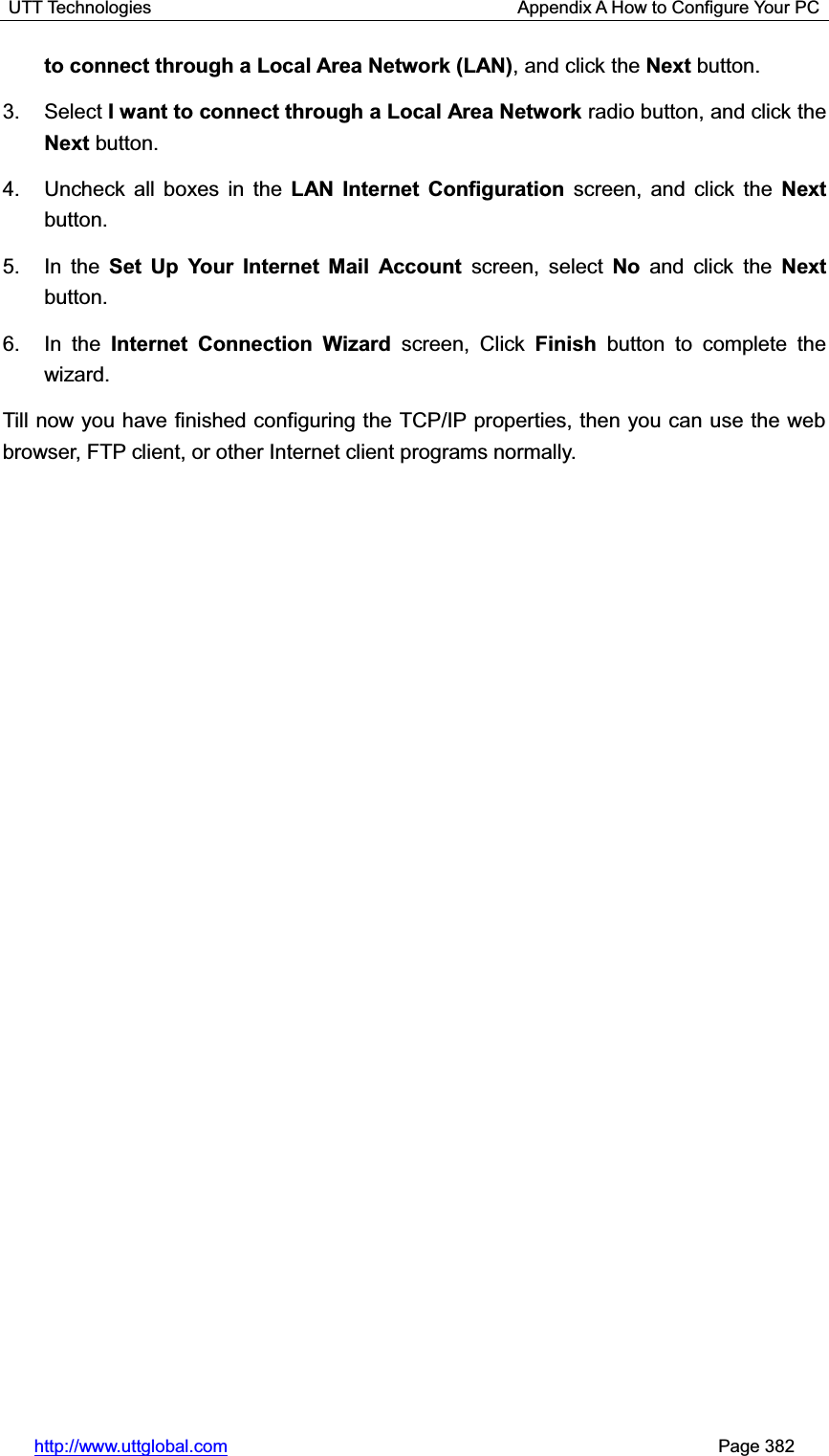
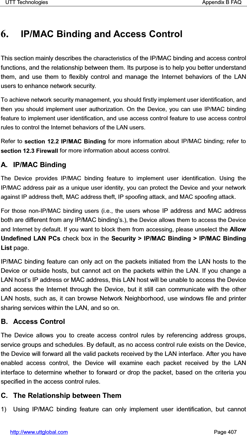
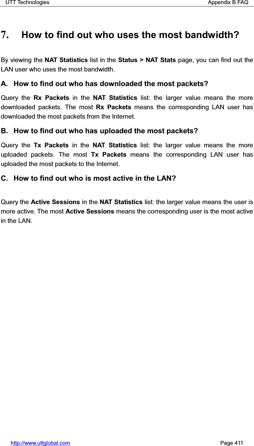
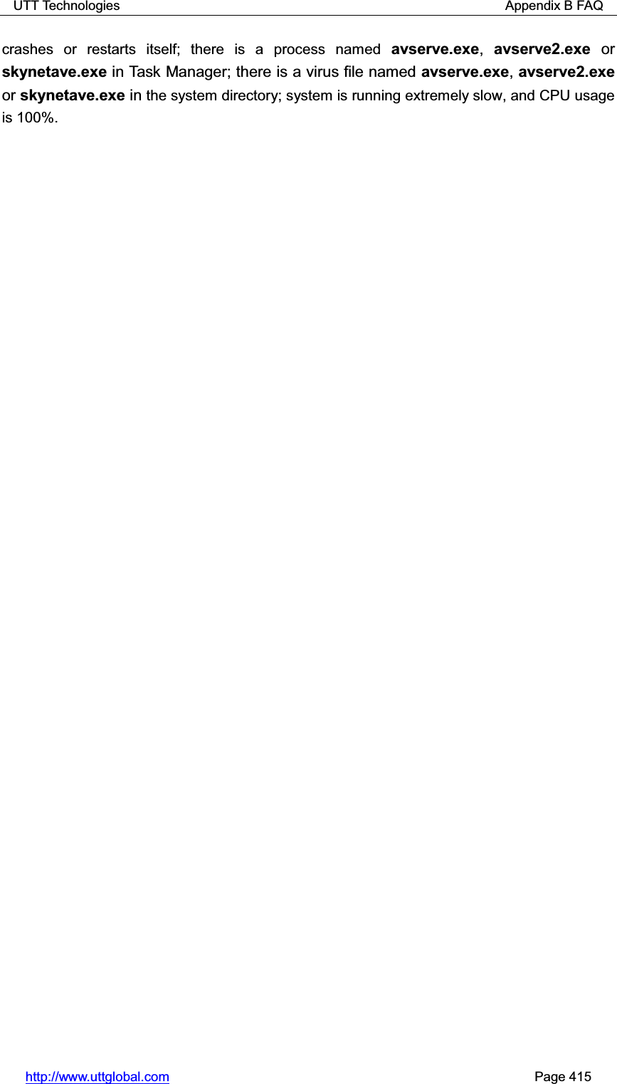
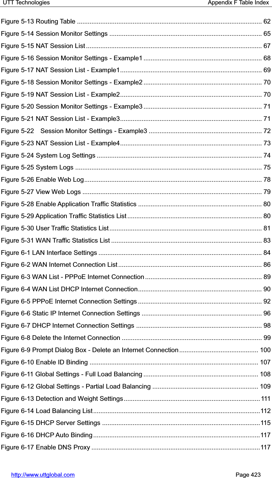
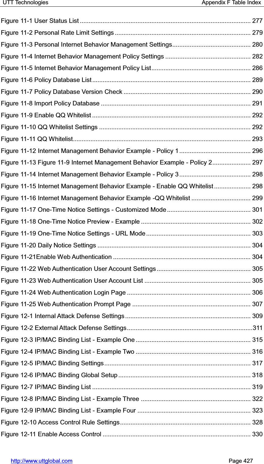
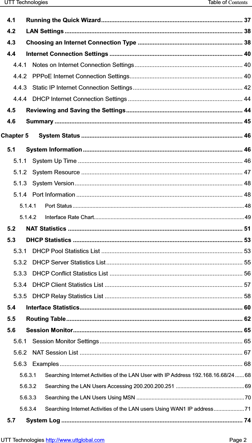
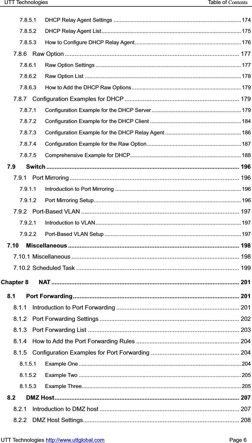
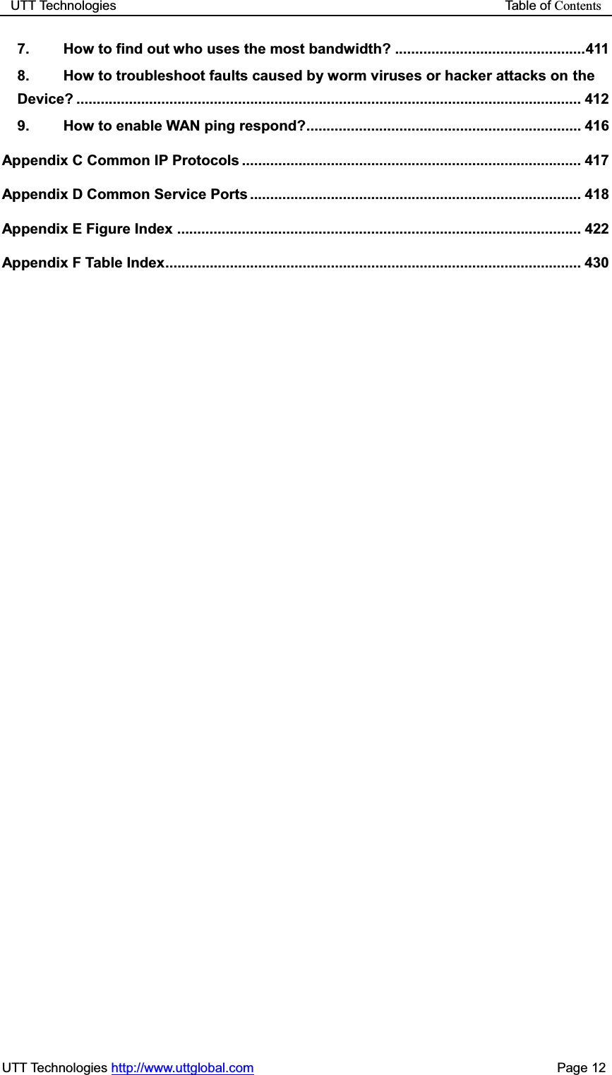
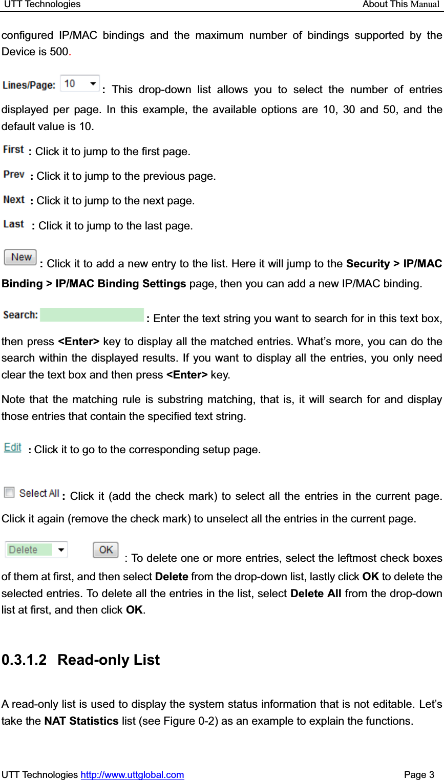
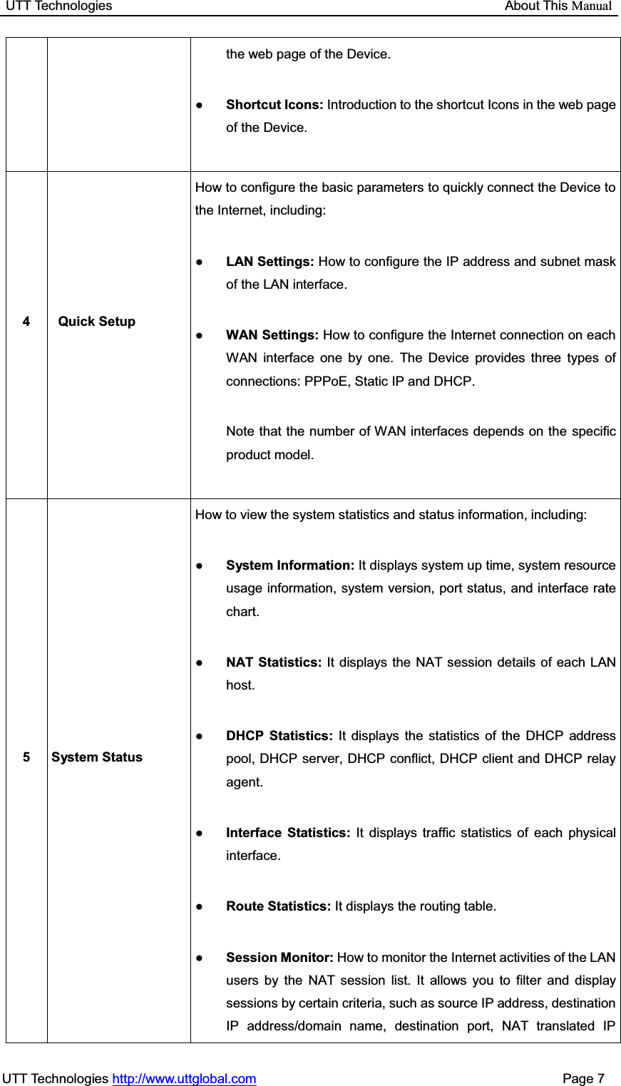
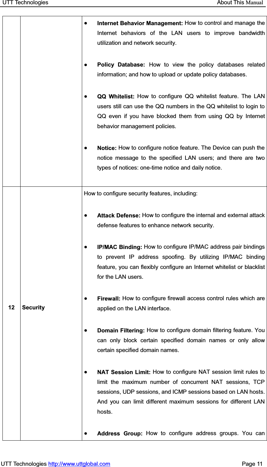
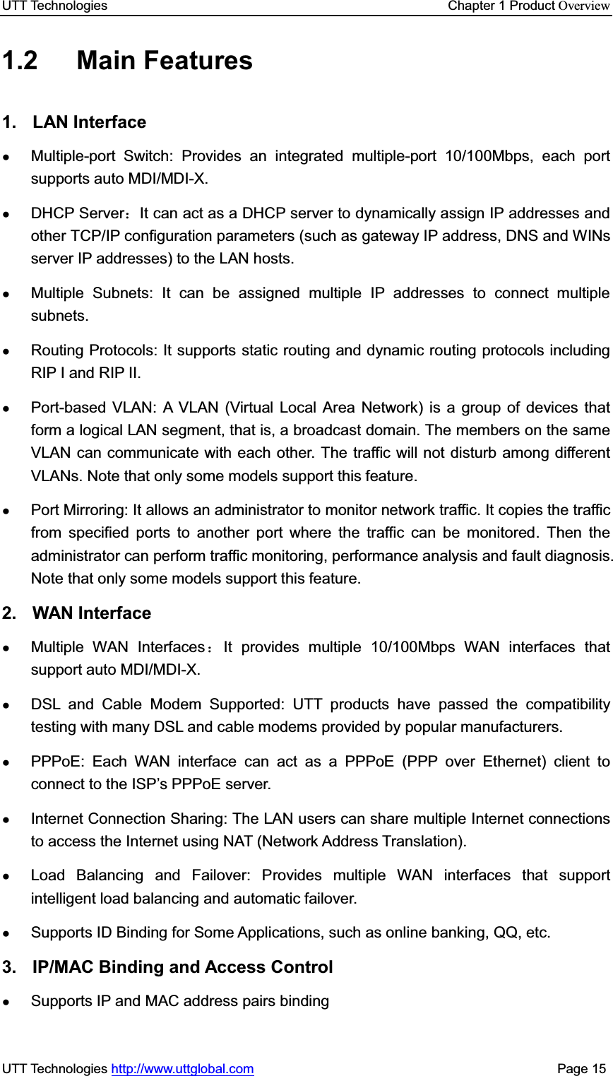
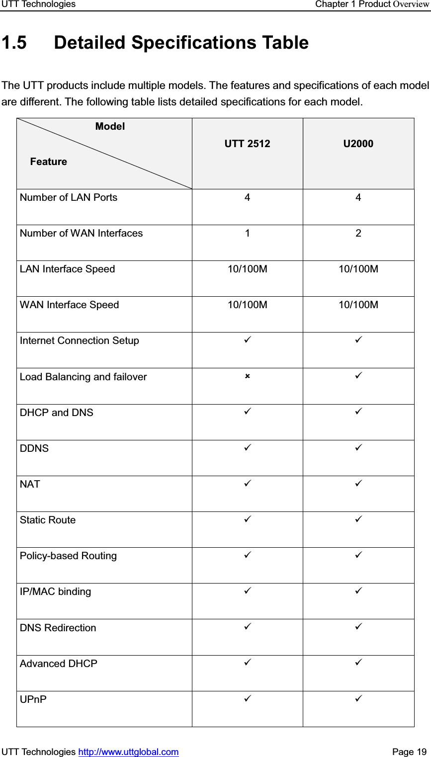
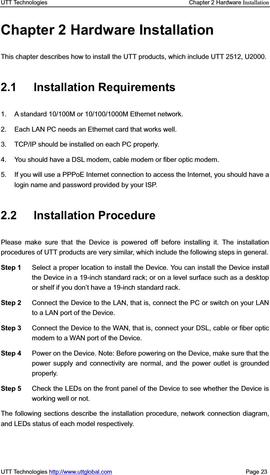
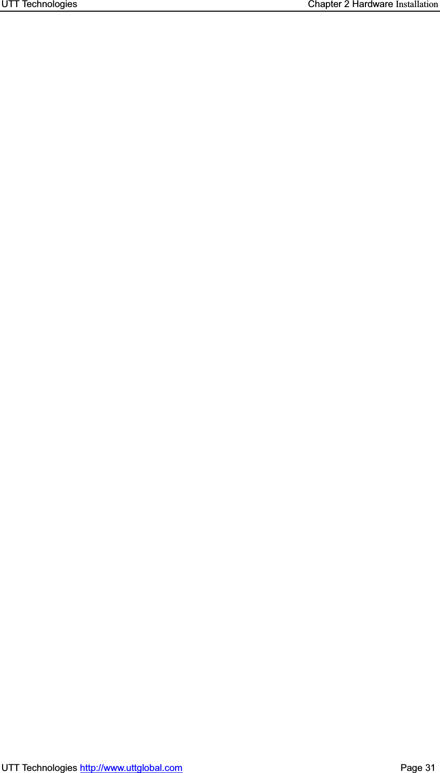
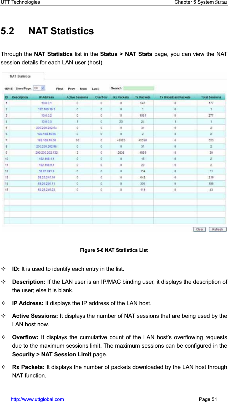
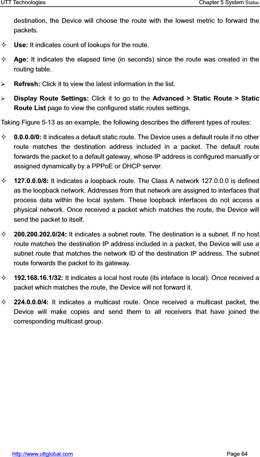
![UTT Technologies Appendix B FAQ http://www.uttglobal.com Page 384 to the PPPoE connection, see Table B-0-1. Call Syslog Call Result Session Up [x] PPPoE Up 00:0c:f8:f9:66:c6 Call Connected, on Line1, on Channel 0 Outgoing Call @51:1-1 PPPoE session has been established successfully. Call Terminated @clearSession: 1 Outgoing Call @51:1-1 Failed to establish the physical connection, please check whether the Internet connection is normal. You may use Windows XP built-in PPPoE dial-in client to test. Call Terminated @clearSession: 1 Call Connected, on Line1, on Channel 0 Outgoing Call @51:1-1 The physical connection has been established, but failed to authenticate. Please go to the Basic > WAN page to check whether the user name and password are correct. If they are correct, please change the PPP Authentication to CHAP or NONE (see Figure B-0-2) and then click the Save button, lastly restart the Device. Table B-0-1 PPPoE Dial-up System Logs](https://usermanual.wiki/UTT-TECHNOLOGIES/REG01-UTT/User-Guide-1659606-Page-399.png)