Unitech Electronics PA520BTNF Rugged Mobile Computer User Manual
Unitech Electronics Co., Ltd. Rugged Mobile Computer
Contents
- 1. User Manual
- 2. Users Manual
User Manual
Rugged Mobile Computer
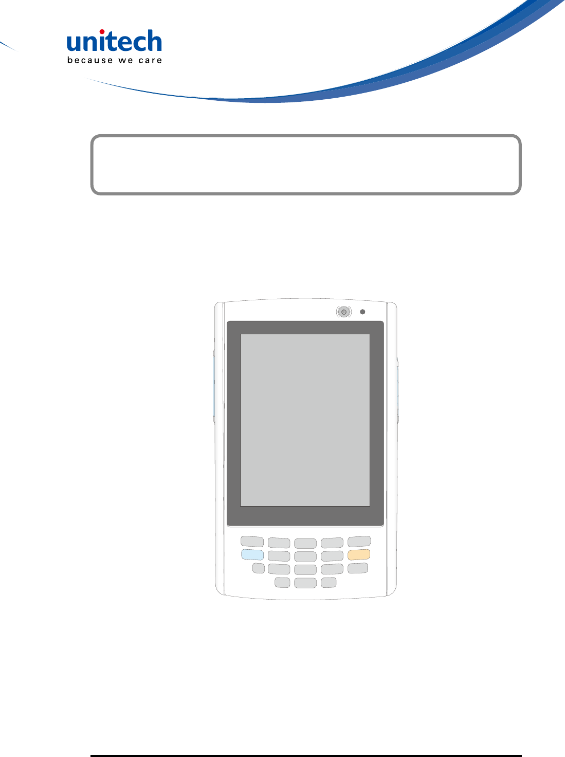
- PA520 -
User's Manual
400892G Preliminary
© 2014 unitech Electronics Co., Ltd. All rights reserved. unitech is a registered trademark of unitech Electronics Co., Ltd.


- I -
This manual explains how to install, operate and maintain the PA520 Data
Collection Terminal.
No part of this publication may be reproduced or used in any form, or by
any electrical or mechanical means, without permission in writing from
the manufacturer. This includes electronic or mechanical means, such as
photocopying, recording, or information storage and retrieval systems. The
material in this manual is subject to change without notice.
© Copyright 2014 Unitech Electronics Co., Ltd. All rights reserved.
Unitech global website address: http://www.ute.com
Bluetooth is a registered trademark of Bluetooth SIG.
Microsoft, Windows and ActiveSync are either
registered trademarks or trademarks of Microsoft
Corporation. Other product names mentioned
in this manual may be trademarks or registered
trademarks of their respective companies and are
hereby acknowledged.
Unitech is a member of Oracle Embedded Software
Licensing Program.
About This Manual
Preface

- II -
Regulatory Compliance Statements
FCC Warning Statement
This equipment has been tested and found to comply with the limits for a Class
B digital device, pursuant to part 15 of the FCC rules. These limits are designed
to provide reasonable protection against harmful interference in a residential
installation. This equipment generates, uses and can radiate radio frequency
energy and, if not installed and used in accordance with the instructions, may
cause harmful interference with radio communications. However, there is no
guarantee that interference will not occur in a particular installation. If this
equipment does cause harmful interference with radio or television reception,
which can be determined by turning the equipment off and on, the user is
encouraged to try to correct the interference by one or more of the following
measures:
– Reorient or relocate the receiving antenna.
– Increase the separation between the equipment and receiver.
– Connect the equipment into an outlet on a circuit different from that to
which the receiver is connected.
– Consult the dealer or an experienced radio/TV technician for help.
1. This Transmitter must not be co-located or operating in conjunction with any
other antenna or transmitter.
2. This equipment complies with FCC RF radiation exposure limits set forth
for an uncontrolled environment. To maintain compliance with FCC RF
exposure requirements, avoid direct contact to the transmitting antenna
during transmitting.
3. Anychangesormodications(includingtheantennas)madetothisdevice
that are not expressly approved by the manufacturer may void the user’s
authority to operate the equipment.

- III -
FCC Label Statement
This device complies with part 15 of the FCC rules. Operation is subject to the
following two conditions:
1. This device may not cause harmful interference, and
2. This device must accept any interference received, including interference
that may cause undesired operation.
RF Radiation Exposure Statement
For body contact during operation, this rugged mobile computer has been
tested and meets FCC RF exposure guidelines when used with an
accessory that contains no metal and that positions the handset a minimum
of 0 mm from the body. Use of other accessories may not ensure
compliance with FCC RF exposure guidelines.
Operations in 5150-5250 MHz band is for indoor use only.
Canadian Compliance Statement
This Class B Digital apparatus meets all requirements of the Canadian
Interference-Causing Equipment Regulations.
Cet appareil numerique de la classe B respecte les exigences du Reglement
sur le material broilleur du Canada.
European Conformity Statement
Declaration of Conformity with regards to the R&TTE 1999/5/EC and EMC
89/336/ EEC directives.
RoHS Statement
ThisdeviceconformstoRoHS(ReductionOfHazardousSubstances)
European Union regulations that set maximum
concentrationlimitsonhazardousmaterialsusedin
electrical and electronic equipment.

- IV -
TaiwanNCC Warning Statement
交通部電信總局低功率電波輻射性電機管理辦法 (930322)
根據交通部低功率管理辦法規定:
第十二條 經型式認證合格之低功率射頻電機,非經許可,公司、商號或使用者
均不得擅自變更頻率、加大功率或變更原設計之特性及功能。
第十四條 低功率射頻電機之使用不得影響飛航安全及干擾合法通信;經發現有
干擾現象時,應立即停用,並改善至無干擾時方得繼續使用。前項合
法通信,指依電信法規定作業之無線電通信。
低功率射頻電機須忍受合法通信或工業、科學及醫療用電波輻射性電
機設備之干擾。
Laser Information
TheUnitechPA520seriesiscertiedintheU.S.toconformtotherequirements
of DHHS/CDRH 21CFR Subchapter J and to the requirements of IEC 825-1.
ClassIIandClass2productsarenotconsideredtobehazardous.ThePA520
seriescontainsinternallyaVisibleLaserDiode(VLD)whoseemissionsdonot
exceed the maximum limits as set forth in the above regulations. The scanner
is designed so that there is no human access to harmful laser light during
normal operation, user maintenance or prescribed service operations.
The laser safety warning label required by the DHHS/IEC for the PA520 series'
optional laser scanner module is located on the memory compartment cover,
on the back of the unit.
CAUTION! Use of controls or adjustments or performance of procedures other
thanthosespeciedhereinmayresultinhazardouslaserlight.
Use of optical instruments with the scanner, including binoculars,
microscopes, and magnifying glasses, with will increase eye
damage. This does not include eyeglasses worn by the user.

- V -
Battery Notices
The PA520 is equipped with a Lithium-Ion battery pack and backup battery.
Both batteries will discharge after an extended period of not being used.
When both batteries are discharged, recharge the unit for 4.5 hours in order to
fully charge the main battery and backup battery. Recharge the PA520 through
the following:
1. Plug the USB charging cable to the PA520 and plug the 5V/3A AC-DC
adapter to the power jack of the USB charging cable.
2. Place the PA520 into the docking station and plug the 5V/3A AC-DC adapter
to the power jack of the docking station.
If the main battery is removed, the backup battery ensures the data on
SDRAM is safe for up to 2 hours. To prevent data loss, do not leave the PA520
uncharged with the main battery removed for an extended period. For more
details, refer to the section titling Charging the Battery.
NOTE: Rechargeable batteries are advised to replace every year or when 500
charge/discharge cycles achieved to guarantee optimal performance. It
is normal that the battery balloons or expands beyond one year or the
maximum of 500 cycles. Although it does not cause harm, it cannot be
used again and must be disposed of according to the location's safe
battery disposal procedures.
If the performance decrease is greater than 20% in a Lithium-Ion
battery, the battery is at the end of its life cycle. Do not continue to use,
and ensure the battery is disposed of properly.
The length of time that a battery power lasts depends on the battery type and
how the device is used. Conserve the battery life through the following:
•Avoid frequent full discharges because this places additional strain on the
battery. Several partial discharges with frequent recharges are better than a
deep one. Recharging a partially charged lithium-Ion battery does not cause
harm because there is no memory.
•Keep the lithium-Ion battery cool. Avoid a hot car. For prolonged storage,
keep the battery at a 40% charge level.

- VI -
•Do not leave the lithium-Ion battery discharged and unused for an extended
period because the battery will wear out and the longevity of the battery will
be at least shorter than half of the one with frequent recharges.
Battery charge notice
It is important to consider the environment temperature whenever the Lithium-
Ionbatterypackischarged.Chargingismostefcientatnormalroom
temperature or in a slightly cooler environment. It is essential that batteries are
charged within the stated range of 0°C to 40°C. Charging batteries outside of
thespeciedrangecoulddamagethebatteriesandshortentheircharginglife
cycle.
CAUTION! Do not charge batteries at a temperature lower than 0°C, which
will increase the internal resistance to cause heat and make the
batteries unstable and unsafe. Please use a battery temperature-
detecting device for a charger to ensure a safe charging
temperature range. Further, to protect and avoid battery from
inating,thebatteryisdetectedforthermalprotectionandwillnot
be charged when the temperature of battery is over 50 degrees.

- VII -
Storage and safety notice
Although charged Lithium-Ion batteries may be left unused for several months,
their capacity may be depleted due to build up of internal resistance. If this
happens they will require recharging prior to use. Lithium-Ion batteries may
be stored at temperatures between -20°C to 60°C, however they may deplete
more rapidly at the higher temperature ranges. It is recommended to store
batteries within normal room temperature ranges.
Warranty
The following items covered under Unitech Limited Warranty are free from
defects during normal use:
• PA520 – 1-year limited warranty.
• Lithium-Ion battery – 6-month limited warranty.
Warrantybecomesvoidifequipmentismodied,improperlyinstalledorused,
dam-aged by accident or neglect, or if any parts are improperly installed or
replaced by the user.
Use only the adapter supplied. Using the wrong adapter may damage the unit
and will void the warranty.

- VIII -
Preface
About This Manual ...... ........................................................................................i
Battery Notices................................................................................... ....................v
Battery charge notice . ...............................................................................................vi
Storage and safety notice ........................................................................................ vii
Warranty .............................................................................................................. vii
Chapter 1
Getting Started .................................................................................................. 1
Introducing the PA520................................................................... ......................... 1
PA520 Product Introduction & Accessory Kit .........................................................2
Tour of the PA520.............................................................................. .....................3
Setting up the PA520............................................................................... ..............5
Installing the Battery............................................................................ ........................5
Charging the PA520.......................................................................... ..........................6
Powering On the PA520.................................................................... ..........................7
Chapter 2
Using the Hardware......................................................................................... .. 9
Using the Keypad...................................................................................... ............. 9
Using the Stylus .....................................................................................................9
Using the SDIO/MMC Slot ...................................................................................10
Table of Contents

- IX -
Chapter 3
Getting Connecte............................................................................................. 13
Establishing Device-PC Connection ....................................................................13
Installing Microsoft ActiveSync ..................................................................................13
Connecting the Device to Your Computer .................................................................14
WiFi Connection. .................................................................................................. 15
Using the Summit Utilities. ........................................................................................15
Chapter 4
Barcode Scanner Programs...................................................................... ...... 19
Scanner Setting....................................................................................................19
Scan2Key ............................................................................................................. 19
Barcode Symbologies ...............................................................................................20
Barcode Symbologies 2D ..........................................................................................21
Chapter 5
Advanced Settings........................................................................................... 23
Performing a Hardware Reset..............................................................................23
Performing a Warm Boot............................................................. ..............................23
Performing a Cold Boot................................................................... ..........................23
Appendix I
SystemSpecication ....................................................................................... 25
Appendix II
Worldwide Support .......................................................................................... 27

- X -

- 1 -
Introducing the PA520
Thank you for purchasing the PA520 Data Collection Terminal. Your PA520 was
designed for users who need a compact and durable portable computer for
data collection and real time transactions. The unitech PA520 Data Collection
Terminal is a compact mobile computing device designed for maximum
durability.
Easy to Use
Theunitisequippedwithacolordisplaywithtouchscreen,ave-way
directional key, and six application keys. The PA520 supports integrated long
range scanners for fast and accurate data collection. The device also supports
infrared interface, Bluetooth, and wireless communication capability for
exchanging information in a computing communication system.
Getting Started
Chapter 1
- 2 -
* The adapter’s replaceable clip plugs is available, depending on the region.
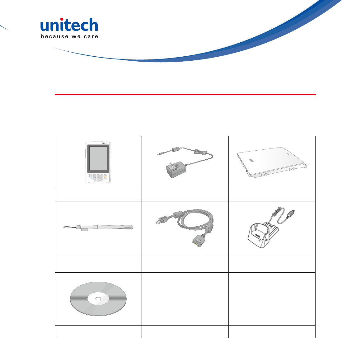
PA520 Product Introduction & Accessory Kit
After opening the box, ensure the following accessories for the PA520 are
present:
PA520 Terminal Power Adapter* Battery Pack
Stylus with bungee
lanyard USB charging cable USB docking station
(optional)
QRG/UM CD-ROM
- 3 -
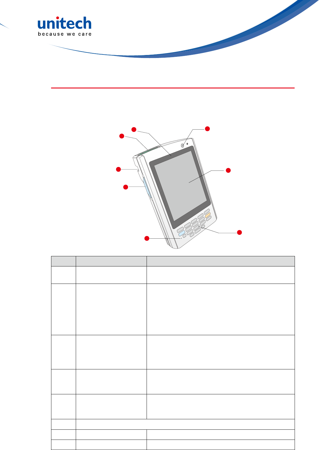
Tour of the PA520
The following sections describe the main components and features of the
PA520.
Front View
No. Component Description
1Barcode laser scanner
(optional)
Reads and captures information on a barcode
label.
2Status indicator
Indicates the battery charging and barcode
scanning status.
Green - Battery is fully charged, the device is
running on battery power, or barcode scanning
Red – Battery is being charged and barcode
scannerisred/activated.
3Power button
If the device is off, press this button to turn it on.
Alternatively, when the unit is on, this key must be
pressed and held down for about two seconds in
order to turn the device off.
4LCD touch screen
Displays the applications and data stored on your
device. It is touch-sensitive and responds to the
stylusornger.
5Keypad
Includes a software keyboard button, navigation
key and application buttons to launch Microsoft
Outlook Mobile programs.
6(Reserved)
7Left scanner trigger key Press to activate the barcode laser scanner.
8Cord holder Eyelet for holding the elastic bungee lanyard.
3
5
6
4
7
8
1
2
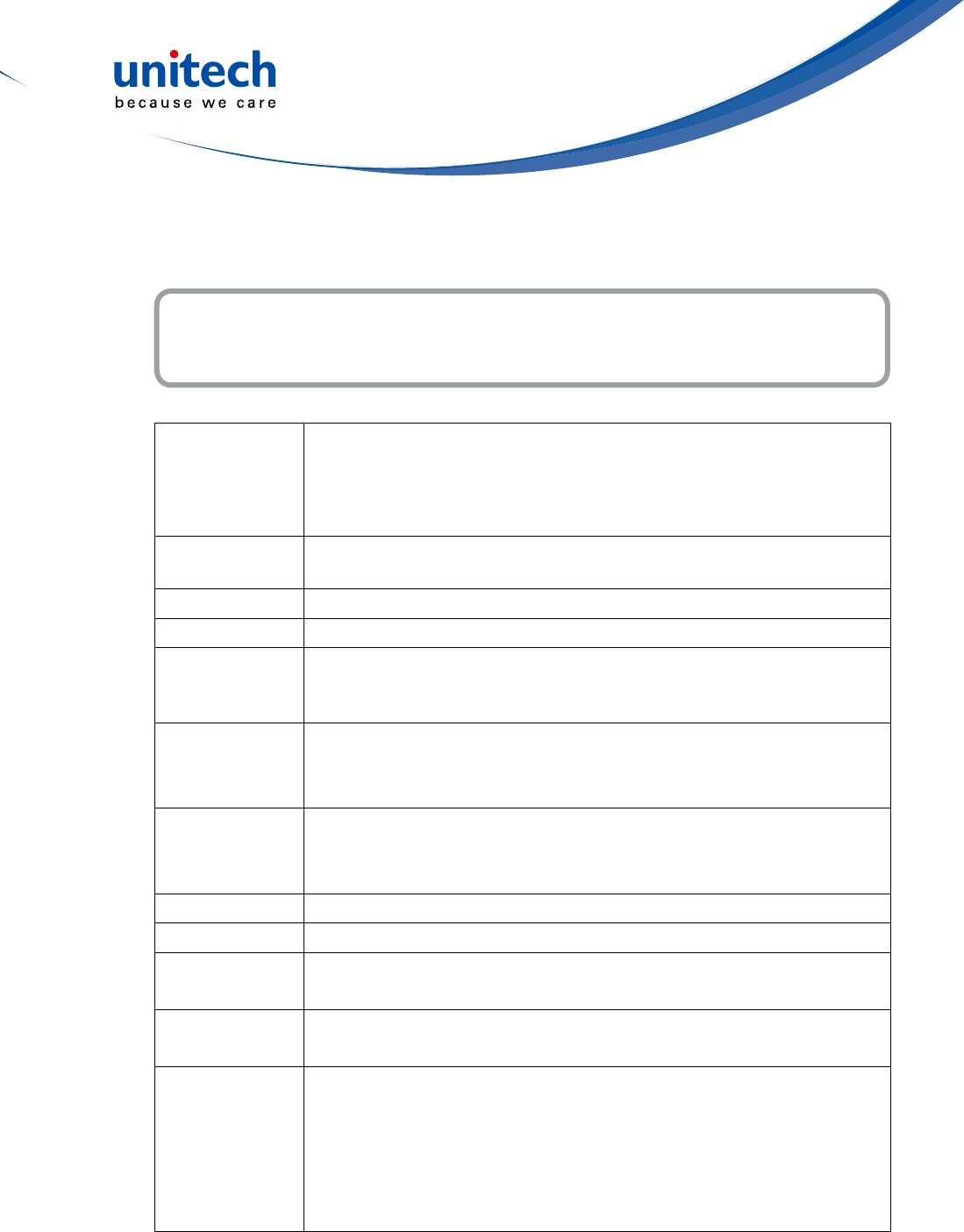
- 4 -
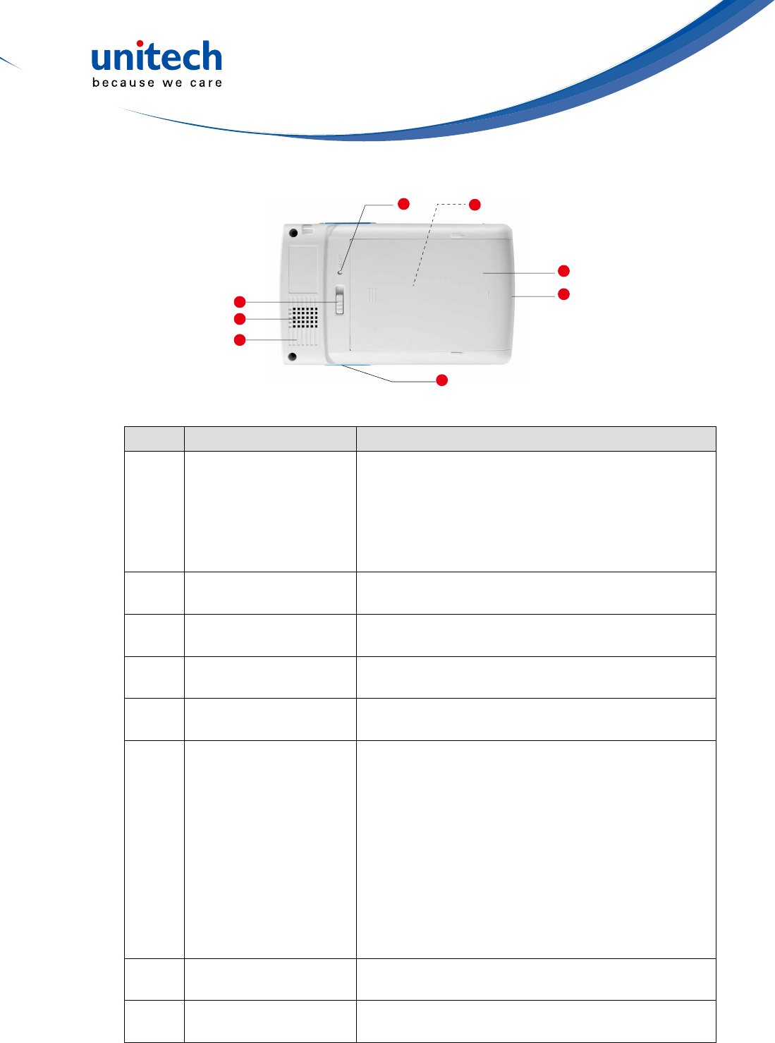
Rear View
No. Component Description
9SDIO/MMC slot
AcceptsanSD(SecureDigital),MMC(Multimedia
Card)orSDIO(SecureDigitalInputOutput)cards,
allowing you to add more memory.
Installadd-onapplicationsoruseaudiotextles
stored in it for use with internal applications. You
can also use it to backup data from your device.
10 Speaker When the speaker is active, sounds are emitted
here.
11 Battery release latch Slide toward the right side of the device and hold
rmly,thendetachthebatteryfromitsbay.
12 Reset button Press the end of the stylus into the button to reset
your device.
13 Main battery Removable and rechargeable 3.7 V, 2200 mAh
battery pack.
14 Universal connector
Connects your device to a USB charging/
communication cable. This USB cable connects to
the computer's USB port and accepts the 5V AC
adapter to provide power to the PA520.
The unit can simultaneously recharge and perform
an ActiveSync operation. You can also use it to
connect peripheral hardware, such as a docking
station, to your device.
This port can also support USB and RS232 hosting
for devices such as a USB or RS232 scanner,
keyboard, or USB memory key.
15 Right scanner trigger
key Press to activate the barcode laser scanner.
16 Stylus To use the stylus, remove it from its holder and
hold it the same way as you hold a pen or pencil.
15
12
10
16
11
13
14
9

- 5 -
Setting up the PA520
Perform the following set up tasks to begin using your device:
• Install the battery pack.
• Charge your device.
• Power on the PA520
Installing the Battery
WARNING! Thereisariskofreandburnsifthebatterypackishandled
improperly. DO NOT disassemble, crush, puncture, short external
contacts,ordisposethebatterypackinreorwater.DONOT
attempt to open or service the battery pack. Dispose of used
batteries according to the local recycling guidelines in your area.
A backup battery cell is embedded into your device to prevent data loss when
the removable battery pack is removed or completely discharged. The backup
battery will keep the data and system settings up to 1 hour if the main battery
is removed.
NOTE: To enable the internal battery cell to provide backup power supply,
charge your device with the main battery pack for at least three and a
half hours.
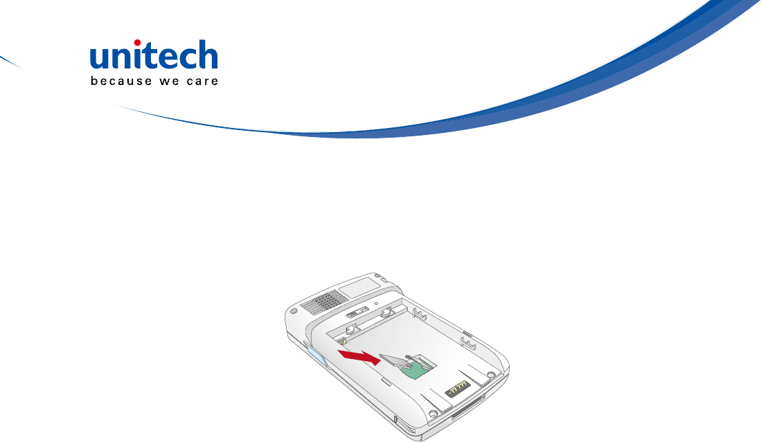
1. Positionthebatterypack,makingsurethebatterypacktstheshapeofthe
battery compartment.
2. Slide the battery pack into the battery bay. The battery pack locks to the
chassis with an audible click.
3. If you remove the main battery and plug it back
before the backup battery lost power, PA520
will be warm start.
4. If you remove the main battery and plug it back
after the backup battery lost power, PA520 will
be clean booted.
- 6 -
Charging the PA520
For initial use, you need to charge your device for about 16 hours. After that,
you can charge it everyday to recharge the battery to full capacity. You can
charge your device using the USB charging cable or the docking station.
CAUTION! OperatingthePA520forthersttimewithouttheACadapter,and
without fully charging the backup battery may result in loss of data
stored in RAM memory.
NOTE: Data you entered may not be properly stored until the internal backup
battery has been fully charged.
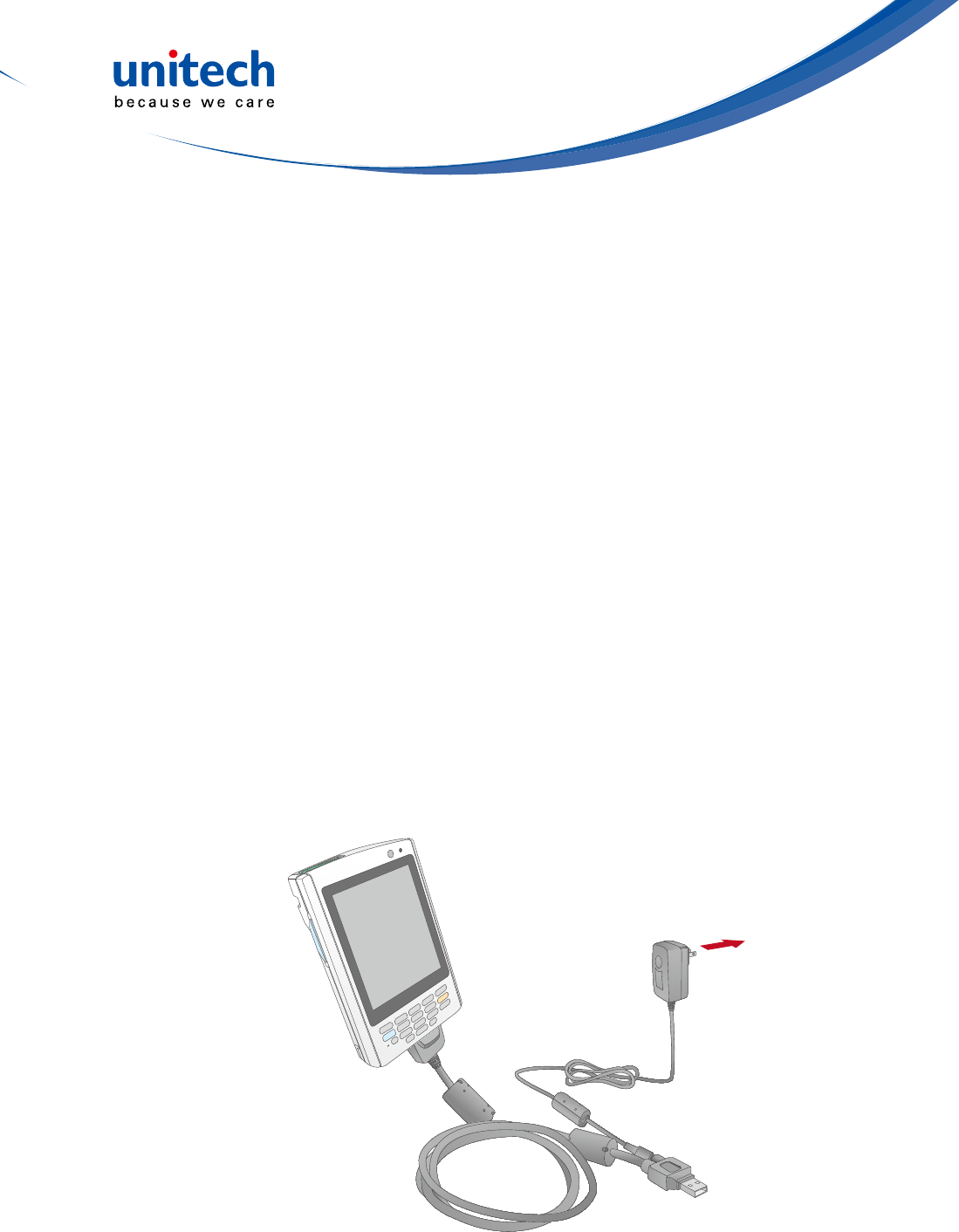
To charge the device using the USB charging cable:
1. Attach the clip plug to the AC adapter, if necessary. Slide the replaceable
clip plug into the AC adapter until it locks into place with an audible click.
2. Press and hold the connector button on the USB charging cable and
connectittothePA520(1).
3. PlugtheACadaptercableintothepowerjackontheUSBchargingcable(2).
4. ConnecttheACadapterintoanelectricaloutlet(3).

- 7 -
The connection is secure when the bottom edge of the device is aligned
smoothly with the docking station, and the LED indicator on the docking sand
device lights up red.
LED status during charging:
– Solid red: Charging
– Solid green: Charging complete
If the battery level becomes low, astatus icon appears on the device screen
indicating low or very low battery status. In both cases, perform an
ActiveSync opetion to back up yourata, and then recharge your device asoon
as possible. If the battery level reaches a low status, the device will entera
sleep mode and cannot be powered up until the battery is charged. Windows
Mobile 5.0 devices will retain installed applications and data when the main
battery is completely drained for extended periods of time.
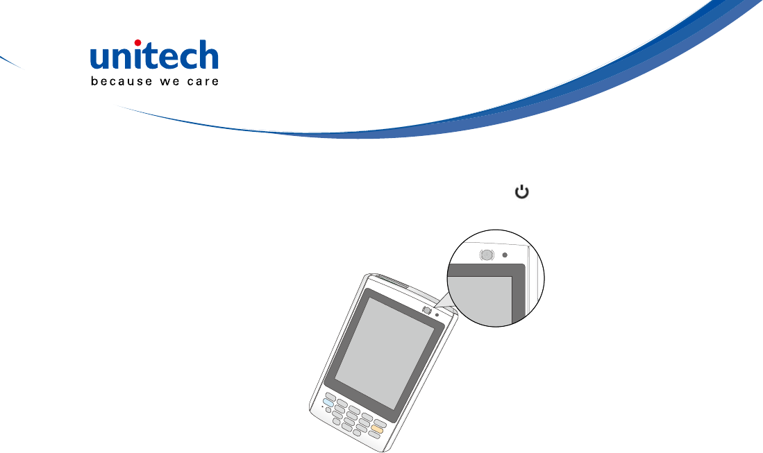
Powering On the PA520
After you have initially charged your device for about 16 hours, the device is
ready to be used. You can now start up your device where you can calibrate
thescreen,setupthesystemtimezone,andlearnsomebasicstylususage.
To charge the device using the docking station:
1. Plug the AC adapter cable into the power jack on the docking station.
2. Plug the AC adapter into an electrical outlet.
3. Slide the device into the docking station until it clicks into place.
- 8 -
1. Turn on your device by pressing the Power button on the front panel.
NOTE: ThePA520screenshipswithaprotectiveplasticlm.Youmayremove
it by peeling from one corner. The screen will be more susceptible to
scratchingwithoutthelm,butwillbemorereadable.
The unitech PA520 welcome screen appears. The Windows Mobile screen
will appear shortly.
2. Calibrate the PA520
The calibrate screen will automatically appear when the unit is powered-
onforthersttimeorafterthesystemisreset.Thisscreencanalsobe
accessedatanytimebytappingStart→Settings→Systemtab→Screen.
The PA520 will prompt you to calibrate the unit by tapping a sequence of
screenlocations.Tapgentlybutrmly.Whenyouhavecompletedtheseries
of taps, press the Enterbuttontoconrmit.
3. Set the Time Zone, Date, and Time
SelectyourcurrenttimezonefromtheTimezonedrop-downmenu,and
then tap Next.
4. Followallonscreeninstructionstocompletethesetup.Thesetupwizard
provides tips for using the pop-up menus and assign a lock password to
access your device.
After the device setup, you can create an ActiveSync partnership to
synchronizeinformationbetweenyourcomputerandyourdevice.See
Establishing Device-PC Connection in chapter 3 for detailed instructions.
- 9 -
Using the Hardware
Chapter 2
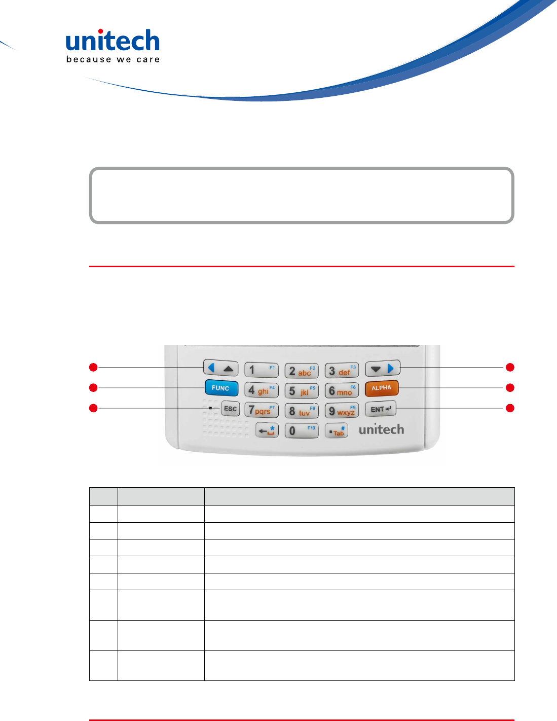
No. Button Name Description
1 ESC Press the ESC button to exit from the section you entered.
2 P1Press P1 to enable Task Manager.
3 P2Press P2 to enable scanner.
4 P3Press P3 to enable Battery.
5 P4Press P4 to enable Device Setting.
6 Enter Press the Enter button to access the menu options and
conrmyourselection.
7 Navigation key Use the up, down, left, and right arrow keys to navigate
through the menu options.
8 OK PresstheOKbuttontoaccessthemenuoptionsandconrm
your selection.
Using the Stylus
CAUTION! Never use anything other than PA520 stylus on the screen;
otherwise this could cause a permanent damage.
Using the Keypad
The PA520 keypad has a navigation key and six special keys to launch
particular applications and display the on-screen keyboard.
2
3
1
5
6
4
- 10 -
1. Push the stylus in the direction of the arrow, then pull out to remove the
stylus from its holder.
2. Hold the stylus like holding a pencil.
3. To make a choice from a menu, lightly tap the tip of the stylus on that choice.
4.Towritedataintoaeldonaform,usethestylustoprintthelettersor
numbers(ofon-screenkeyboard).Useverylightpressure.
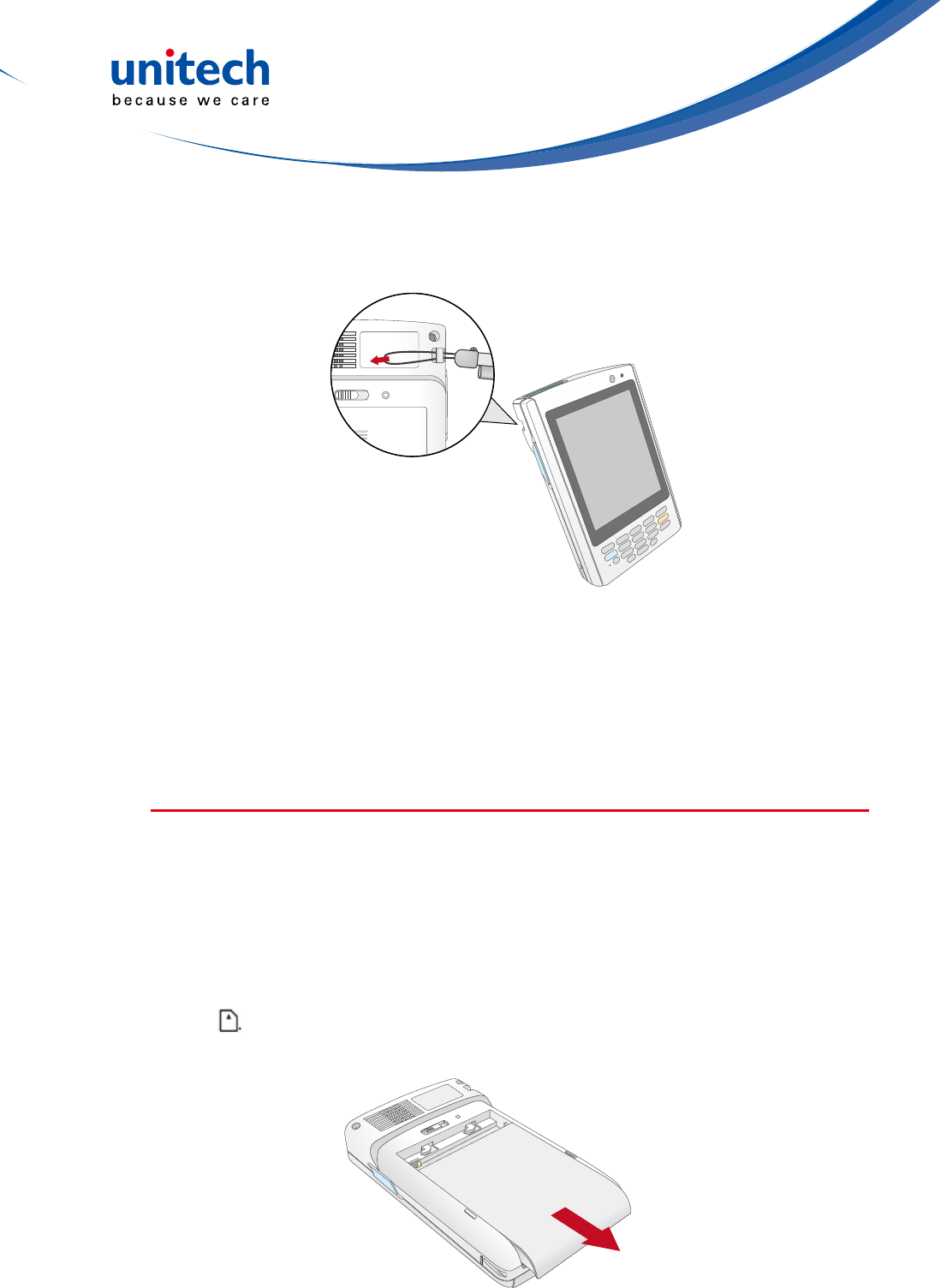
Using the SDIO/MMC Slot
Your device has an expansion slot compatible with a range of SD, SDIO, and
MMCstoragecards,whichareprimarilyusedtobackuportransferlesand
data.
T0 Insert a storage Card:
1. Hold the device securely, and then lift the rubber cover from the SDIO/MMC
slot .
- 11 -
2. Push the card into the slot until you feel the SD card click into place, and
this will signal that the card is already properly seated in the slot.
The card is secure when it is not prot ruding from the slot.
To remove a storage card:
1. Hold the device securely. Push the card in and release. The card pops out.
2. Remove the card from the slot.

- 12 -

- 13 -
Getting Connected
Chapter 3
The PA520 enables users to link to a host computer using an RS-232, or
Bluetooth, WiFi, and GPRS connection for data communication. This chapter
provides an over-view of PA520 communication options.
Establishing Device-PC Connection
Installing Microsoft ActiveSync
In order to exchange data between your computer and the PA520, Microsoft
Active-Sync must be installed on your computer. Use the USB/RS232 charging
cable that comes with your device or the docking station to connect the device
to your computer.
NOTE: If you have a previous version of the Microsoft ActiveSync installed
in yourcomputer,uninstallitrstbeforeinstallingthelatestversionof
Microsoft ActiveSync.
To install Microsoft ActiveSync on your computer:
1. Close any open programs, including those that run at startup, and disable
any virus-scanning software.
2. Download the ActiveSync software from the Microsoft ActiveSync Download
page at
http://www.microsoft.com/downloads/details.aspx?Fami-lyID=7269173a-
28bf-4cac-a682-58d3233efb4c&DisplayLang=en.
3. Browsetothelocationofthedownloadedle,anddouble-clickit.The
installationwizardbegins.
4. Follow the instructions on the screen to install Microsoft ActiveSync.

- 14 -
Connecting the Device to Your Computer
1. After ActiveSync has been installed,
connect PA520 to your PC as described
inconnectingtheterminaltoahost(PC/
Notebook)toaPC.
2. Turn the PA520 on.
3. ActiveSync starts automatically and
conguretheUSBporttoworkwith
the PA520. The New Partnership setup
wizardautomaticallystarts.
NOTE: IfActiveSyncdoesn’tstartautomatically,clickStart→Programs→
Microsoft ActiveSync.
NOTE: If a message appears indicating that it is unable to detect a connection,
clicktheCancelbuttonandmanuallycongurethecommunication
settings.
4. Follow the on-screen instructions.
5. Whenthecongurationprocessis
complete, the Active-Sync window
appears.
6. Synchronizationwillbeinitializedandwilltakeplaceifyou’vechosento
synchronizeperiodicallyoruponconnection.
NOTE: Your computer can create a partnership with multiple PA520s. Also, a
PA520 can create a partnership with up to two computers.
- 15 -
WiFi Connection
Unitech terminals come with built-in RF facility. A wireless network can be
added either when the network is detected or by manually entering settings
information. Before following these instructions, make sure if authentication in
formation is needed.
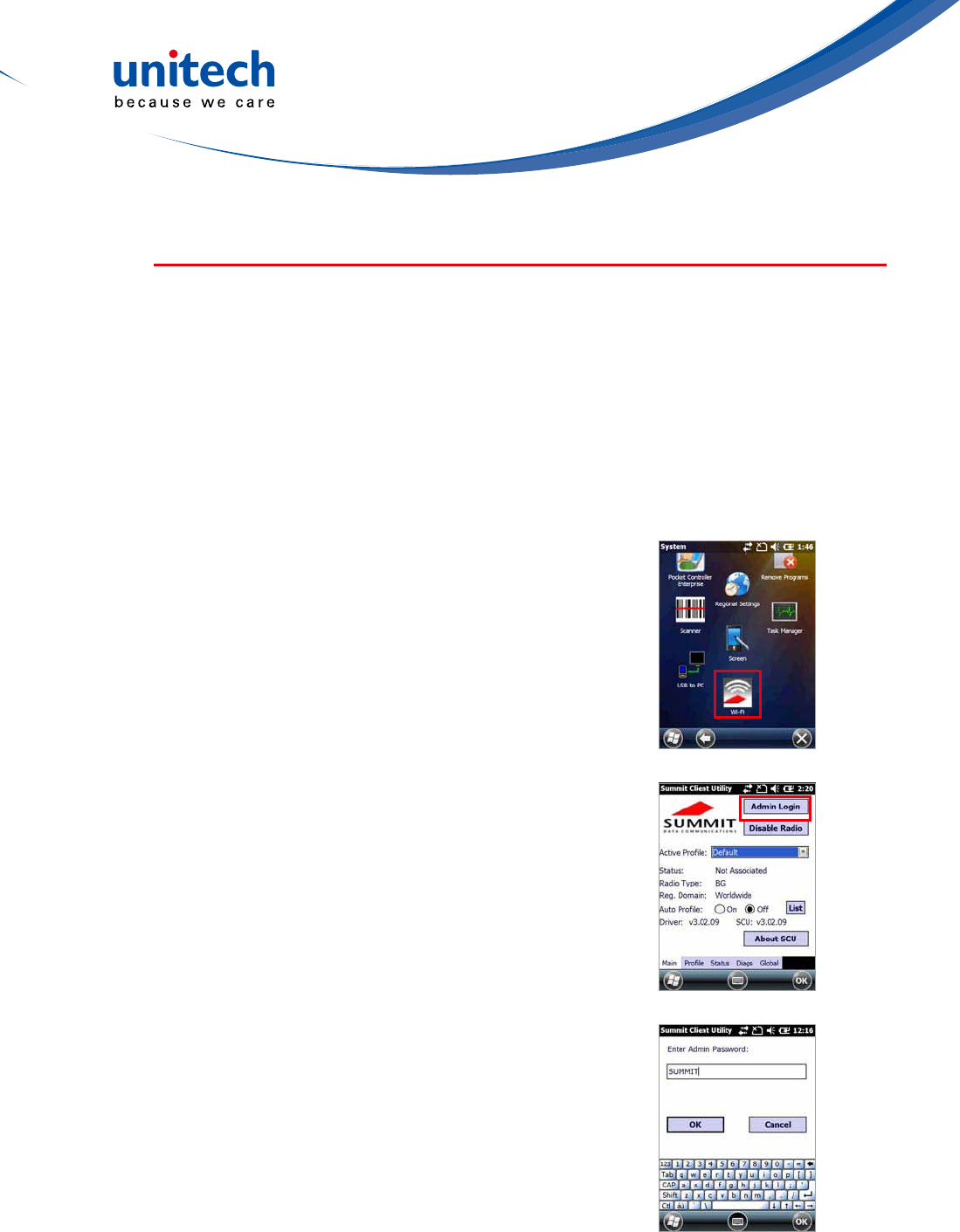
Using the Summit Utilities
You can use the Summit Client Utility tool to setup or change the WiFi settings.
1. TapStart→Setting→System→Wi-Fi.
The Summit Client Utility window appears.
2. To login as an administrator, tap Admin Login.
3. EntertheAdminPassword.(Defaultpassword:
SUMMIT)
- 16 -
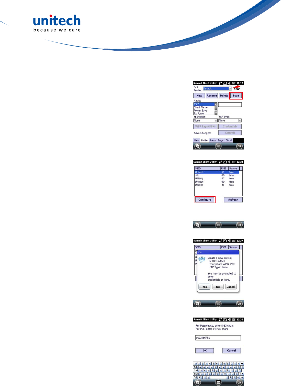
Scan Available AP
1. UnderProletab,tapScanforavailableAP.
2. You may select a desired AP to create a new
prole.TapCongure.
3. TapYestocreatethenewprole.
4. Enter the WEP key or network key. Tap OK.
- 17 -
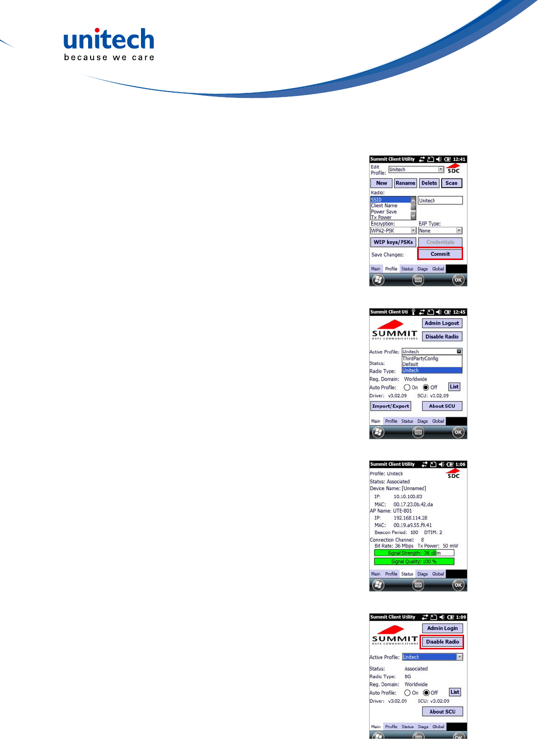
Commit and Activate
1. Tap Commit to activate the setting.
2. UnderMaintab,selecttheproleyouwantto
activate.
3. Under Status tab, you can see the IP address,
signal strength and quality.
4. Tap OK to exit the Summit Client Utility.
5. TapStart→Boot-Mode.TapWarmBootto
warm start the terminal and load the previous
settings.
6. If you want to disconnect the AP, tap Disable
Radio.

- 18 -
- 19 -
Barcode Scanner Programs
Chapter 4
PA520 provides an option for the barcode scanner, allowing you to scan and
decode various types of 1D/2D barcodes.
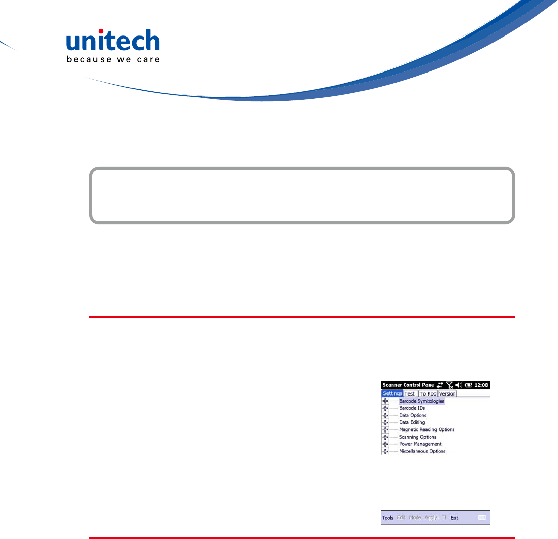
Scanner Setting
When it is necessary for the user to change the default barcode symbology for
a different application, the Scanner Control Panel provides the ability to change
default symbology, place delimiter characters behind scanned data, and save
the settings.
TapStart→Settings→System→Scanner.
The Scanner Control Panel appears.
NOTE: Press Func key and “7” button.
Scan2Key
The Scan2Key application routes input from a scanner port to a keypad
buffer, making all input from the scanner emulate input from the keypad.
Using Scan2Key, scanned data will be directed from the scanner port to any
waiting(active/focused)texteditorsuchasMSMobileWordoratextboxinan
application.

- 20 -
Barcode Symbologies
Barcode
Symbology
Enable /
Disable
Char Check
/ Digit
verication
Transmit
Check Char
/ digit
Others
Australian
Post YES Send bar width data
British Post YES
Canadian
Post YES
Codabar YES YES YES Transmit start & stop char,
*data length
Code 11 YES YES *data length
Code 128/
EAN 128 YES *data length
Code 39 YES YES YES
For ASCII, Transmit start &
stop char, Append mode,
*data length
Code 93 YES *data length
Dutch(KIX)
Post YES
EAN 13 YES YES
2 digit addenda, 5 digit
addenda, Addenda required,
Include addenda separator
EAN 8 YES YES
2 digit addenda, 5 digit
addenda, Addenda required,
Include addenda separator
IATA 2 of 5 YES *data length
Interleaved
2 of 5 YES YES YES *data length
ISBT YES
Japanese
Post YES
Korean Post YES *data length
Matrix 2 of 5 YES *data length
MSI YES YES *data length
Planet YES YES
Postnet YES YES
RSS
(Databa YES YES *data length

- 21 -
Barcode
Symbology
Enable /
Disable
Char Check
/ Digit
verication
Transmit
Check Char
/ digit
Others
UPC A YES
2 digit addenda, 5 digit
addenda, Addendse a
required, Include addenda
parator, Send number
system
UPC E YES YES
2 digit addenda, 5 digit
addenda, nd number system,
Addenda required, Include
addenda separator, Se
Expanded UPC-E
UPC E1 YES YES
2 digit addenda, 5 digit
addenda, Addenda required,
Include addenda separator,
Send number system,
Expanded UPC-E
NOTE: *Value Adjustable Scanner Control Panel Version 5.14
Barcode Symbologies 2D
Barcode
Symbology
Enable /
Disable
Char Check
/ Digit
verication
Transmit
Check Char
/ digit
Others
Aztec YES Runes, *data length
Codablock F YES *data length
Code 49 YES *data length
Data Matrix YES *data length
EANEAN-
UCC
Composite
YES UPC composite, *data length
MaxiCode YES *data length
MicroPDF -
417 YES *data length
OCR YES
PDF- 417 YES *data length
QR Code YES
TLC-39
(TCIFLinked
Code39)
YES
NOTE: *Value Adjustable Scanner Control Panel Version 5.14

- 22 -
- 23 -
Advanced Settings
Chapter 5
Performing a Hardware Reset
Youmayhavetoperformaresetifthedevicefreezes(i.e.,thedeviceno
longerrespondstothebuttonsortappingonthescreen).
A soft reset allows your device to get a fresh start, similar to rebooting a
computer.
This will restart your device and adjust memory allocation. All records and
entries are retained after a soft reset. Unsaved data in open programs may be
lost.
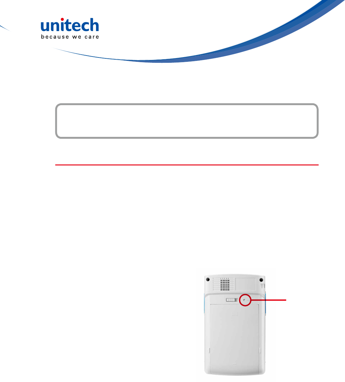
Performing a Warm Boot
1. Remove the stylus from its holder.
2. Lightly press the tip of the stylus to
the reset button located at the rear
side of the terminal.
Performing a Cold Boot
A cold boot will erase all data and all programs you have added, and will
restore the device to the default factory settings.
Never perform a cold boot unless a warm boot does not correct your problem.
When you perform your next ActiveSync operation, you can restore any data
thatyoupreviouslysynchronizedtoyourcomputeroryoucanrestoredatathat
you backed up to a storage card..
Reset button
- 24 -
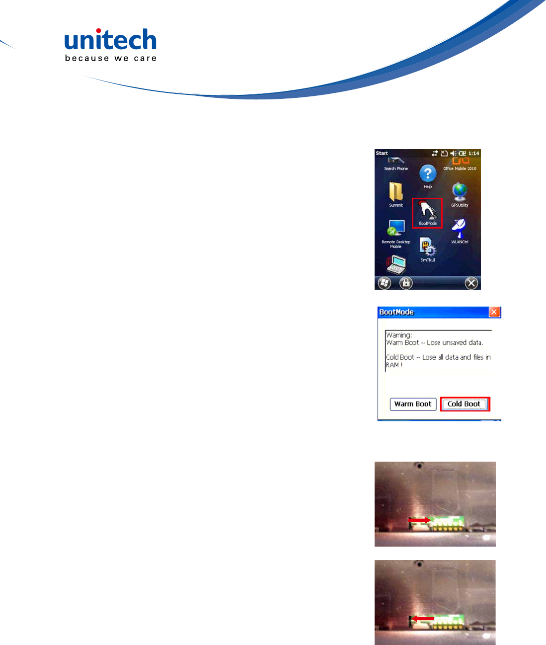
Method 1: From Windows Mobile
1.TapStart→BootMode.
The BootMode Screen appears.
2. Tap Cold Boot.
The system is reset and you will lose all data
includingalllesintheRAMmemory.
Method 2: From Hardware
1. Remove the battery compartment cover and
the main battery. See the section of Installing
the Battery.
2. Turn the backup battery switch off.
3. Turn the backup battery switch on.
4. Cover the battery compartment with the battery.
NOTE: When you perform hard reset, the data
and time settings will not be retained.
Formats, preferences, and other settings
are restored to their default factory
settings.
- 25 -
System Specication
Appendix I
System
CPU:MarvellPXA320Processor,806MHz
Mobile DDR RAM: 256MB
NAND Flash RAM: 512MB
OS: Windows Embedded Handheld 6.5 Classic
Display Transectivecolor3.5”QVGAwithbacklight240×320touchpanel
LCD
Keypad 4 function keys + Navigation keys
Notication LED
Symbologies
1D Barcode EngineUPC-A/E, EAN-8/13, Codabar, Code 39, Code
39 full ASCI, Code 93,Code32, Interleaved & Std. 2 of 5, EAN 128,
Code 11, Delta, MSI/Plessey,Code 128, Toshiba
Indicator
Dual Function LED
Green(Datascanning)
Red(Chargingstatus)
Communication
USB: USB1.1 Host & Client
WLAN: IEEE 802.11 b/g/n
PAN: Bluetooth 2.1 + EDR
Audio 0.8 Watts Speaker
Expansion Slot SDMemorywithSDHCSupport(upto32GB)
Power Source Main Battery: 8.14 Watt-Hour 3.7V @2200 mAh
Backup Battery: Ni-Mh battery Supports 2 hours backup
Enclosure Weight:213g(withbattery)
Dimension:126mm(L)x25mm(H)x77mm(W)
Environmental
OperatingTemperature:14°Fto122°F(-10°Cto50°C)
StorageTemperature:-4°Fto140°F(-20°Cto60°C)
ChargingTemperature:32°Fto104°F(0°Cto40°C)
RelativeHumidity:5%~95%(non-condensing)
DropTesttoConcrete:3feet(90cm)on6faces/4cornersto
concrete

- 26 -
Software Microsoft Visual Studio 2005/2008
Auto Installer
Mobile Device
Management
Software and
Service
12Manage:Softwareandcongurationmanagement,Asset
tracking, remote diagnostics and performance measurement
(Formoredetailedinformation,pleasevisit
http://portal.unitech.eu/RDM/v2/v2login.aspx
Accessories
USB cradle with battery charger
Mainbattery(2200mAh)USBcommunicationandchargingcable
AC adaptor
Regulatory
Approvals CE, FCC, BSMI, VCCI, CCC, RoHS compliance

- 27 -
Worldwide Support
Appendix II
Unitech’s professional support team is available to quickly answer questions or
technical-related issues. Should an equipment problem occur, please contact
the nearest Unitech regional service representative. For complete contact
information please visit the Web sites listed below:
Region Web Site
Global Operation Center http://www.ute.com
Unitech Taiwan http://tw.ute.com
UnitechAsiaPacic&MiddleEast http://apac.ute.com
http://india.ute.com
Greater China Division http://cn.ute.com
Unitech Japan http://jp.ute.com
Unitech North America http://us.ute.com ; http://can.ute.com
Unitech Latin America http://latin.ute.com
Unitech Europe http://eu.ute.com