Verifone MX900-04BTWIFI I/O module User Manual MX900Install

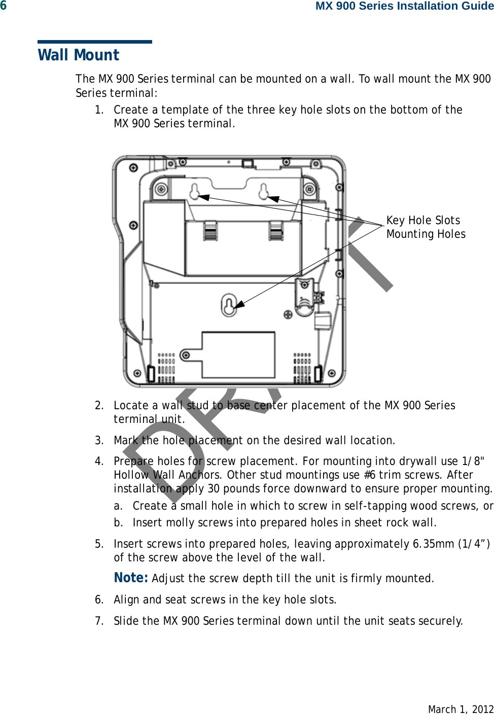
VeriFone Inc I/O module MX900Install

User Manual

DRAFTMX 900 SeriesInstallation Guide
DRAFT
DRAFTMX 900 Series Installation GuidePart Number SPC132-022-01-A, Revision AMarch 1, 2012VeriFone®, Inc.2099 Gateway PlaceSuite 600San Jose, CA 95110Telephone: 408-232-7800http://www.verifone.comPrinted in the United States of America.© 2012 by VeriFone, Inc.No part of this publication covered by the copyrights herein may be reproduced or copied in any form or by any means — graphic, electronic, or mechanical, including photocopying, taping, or information storage and retrieval systems — without written permission of the publisher.The contents of this document and all features and specifications are subject to change without notice. The information contained herein does not represent a commitment on the part of VeriFone, Inc.Publications are not stocked at the address given above. Requests for VeriFone publications should be made to your VeriFone representative.VeriFone, the VeriFone logo, and Ruby SuperSystem are registered trademarks of VeriFone, Inc. Sapphire, Topaz, HPV-20, Ruby Manager, Everest, EASY ID, Electronic Journal On-site, and Ruby Card are trademarks of VeriFone, Inc. in the U.S. and/or other countries. All other trademarks or brand names are the properties of their respective holders.
DRAFT
DRAFTMarch 1, 2012Contents1. Introduction. . . . . . . . . . . . . . . . . . . . . . . . . .   1Intended Audience . . . . . . . . . . . . . . . . . . . . . . . . . .  1Document Organization . . . . . . . . . . . . . . . . . . . . . . .  1Modifications to this document  . . . . . . . . . . . . . . . . . . . .  1Acronyms, Abbreviations, and Definitions  . . . . . . . . . . . . .  22. Hardware Installation . . . . . . . . . . . . . . . . . . .   3Installing the Device  . . . . . . . . . . . . . . . . . . . . . . . . . . .  3To unpack the shipping carton. . . . . . . . . . . . . . . . . . . . .  3Selecting a Location  . . . . . . . . . . . . . . . . . . . . . . . . . . .  4Stand Mount. . . . . . . . . . . . . . . . . . . . . . . . . . . . . . . . .  5Wall Mount. . . . . . . . . . . . . . . . . . . . . . . . . . . . . . . . . .  6PIN Protection Measures. . . . . . . . . . . . . . . . . . . . . . . . .  7Installing Optional Components . . . . . . . . . . . . . . . . . . . .  8Installing Countertop Wedge. . . . . . . . . . . . . . . . . . . .  8Removing or Installing the I/O Module  . . . . . . . . . . . . .  9Installing MSAM or SD Cards  . . . . . . . . . . . . . . . . . . .  10Installing the Stylus and Holster  . . . . . . . . . . . . . . . .  14Removing the Privacy Shield . . . . . . . . . . . . . . . . . . .  16Connecting the Device . . . . . . . . . . . . . . . . . . . . . . . . .  17I/O Module  . . . . . . . . . . . . . . . . . . . . . . . . . . . . . .  17Multiport Cable  . . . . . . . . . . . . . . . . . . . . . . . . . . .  18Connecting ECR in Tailgate Mode. . . . . . . . . . . . . . . .  20Connecting to a Host PC. . . . . . . . . . . . . . . . . . . . . .  21Connecting to the Ethernet LAN  . . . . . . . . . . . . . . . .  21Connecting to USB Host or Hub . . . . . . . . . . . . . . . . .  21Powering up. . . . . . . . . . . . . . . . . . . . . . . . . . . . . . . .  22Using the I/O Module. . . . . . . . . . . . . . . . . . . . . . . .  22Using the Multiport Cable. . . . . . . . . . . . . . . . . . . . .  23Calibrate Touch Screen  . . . . . . . . . . . . . . . . . . . . . . . .  243. Maintenance  . . . . . . . . . . . . . . . . . . . . . . . . . 25
DRAFTii MX 900 Series Installation GuideMarch 1, 2012Cleaning the Terminal. . . . . . . . . . . . . . . . . . . . . . . . . . 25Cleaning the Display Screen . . . . . . . . . . . . . . . . . . . . . . 25Magnetic Stripe Cleaner. . . . . . . . . . . . . . . . . . . . . . . . . 25Smart Card Reader . . . . . . . . . . . . . . . . . . . . . . . . . . . . 254. Terminal Specifications. . . . . . . . . . . . . . . . . . 27Terminal Specifications. . . . . . . . . . . . . . . . . . . . . . . . . 27
DRAFTMarch 1, 20121 INTRODUCTIONThis installation guide is your primary source of information for setting up and installing the MX 900 Series terminals, the MX 915™ and MX 925™. Intended AudienceThis guide is useful for anyone installing and configuring the MX 900 Series terminals. A basic description of terminal features is also provided.Document OrganizationThe following chapters are included:Chapter 1, Introduction, explains the Intended Audience, Document Organization, and common acronyms, abbreviations, and definitions used.Chapter 2, Installation, explains how to install the MX 900 Series terminals.Chapter 3, Maintenance, explains how to maintain your MX 900 Series terminals.Chapter 4, Specifications, provides information on power, environment, and dimensions of the hardware.Modifications to this documentThis document may be changed or extended to include new product requirements.
DRAFT2MX 900 Series Installation GuideMarch 1, 2012Acronyms, Abbreviations, and DefinitionsThe following table describes the common acronyms, abbreviations, and definitions used:Convention MeaningBFI Buffer Flush Intervalbps bits per secondCRC Cyclic Redundancy CheckFA File AuthenticationFirmware Software in FLASH/ROMFTP File Transfer ProtocolGISKE Global Interoperable Secure Key ExchangeiPKG The Itsy Package Management SystemIPP Internal PIN PadISR Interrupt Service RoutineJFFS2 Journaling Flash File SystemKLK VSS Key Loading KeyKSN Key Serial NumberKVC Key Verification CodeLED Light Emitting DiodeMS Master SessionMSR Magnetic Stripe ReaderNFS Network File SystemOSS Open Sound SystemPED PIN Entry DevicePEK PIN Encryption KeyRFCR RF Card ReaderRRT Receive Record ThresholdRTC Real-time ClockSAM Security Access ModuleVRK  VeriShield Remote KeyVSS VeriShield Security Scripts
DRAFTMarch 1, 20122 HARDWARE INSTALLATIONThis chapter describes the MX 900 Series installation procedures and includes connection examples.Installing the DeviceThis section presents installation guidelines for the MX 900 Series terminal.Unpacking Open the shipping carton and carefully inspect the contents for possible tampering or shipping damage.Warning:Do not use a damaged terminal.To unpack the shipping carton1. With the shipping carton right side up, open the top and remove all items from the carton:– Terminal unit– Power pack (Separate Packaging)–Berg retainer2. Remove the protective plastic wrap from the display and other components.Berg RetainerPower Pack(Separate Carton)
DRAFT4MX 900 Series Installation GuideMarch 1, 20123. Place the components on a table or countertop.4. Save the shipping cartons and packing material for repacking or moving in the future.Selecting a LocationWarning:The MX 900 Series terminal is designed for indoor use only.Use the following guidelines to select a location for the MX 900 Series terminal.1. Select a location for the terminal that offers adequate ventilation and protection and is convenient for the user and merchant.2. Place the MX 900 Series terminal on a flat surface, such as a table or countertop, or mount it on a mounting stand supplied by VeriFone. Avoid areas with:– Excessive heat or dust– Oil or moisture– Devices that cause excessive voltage fluctuations or electrical noise, such as air conditioners, fans, electric motors, neon signs, or high-frequency security devices must be no closer than 24 inches– Direct sunlight or objects that radiate heatNote: Interference Sources:Special care is required when mounting the MX 900 Series terminal in sites that utilize anti-theft devices positioned at doorways or surface mounted deactivator pads. Devices of this type, such as Sensormatic brand devices, generate strong electromagnetic fields which may interfere with MX 900 Series terminals. Always select mounting locations at least 6 feet from doorway units and at least 18 inches from surface mounted deactivator pads. Note: Mounting Considerations:VeriFone recommends the use of an approved stand for all mounting situations. Position the terminal conveniently in relation to power, ECR and LAN connections. Ensure the MX 900 Series terminal is located in a manner that allows customers to swipe their magnetic cards or insert their Smart Cards in a smooth and comfortable motion without encountering obstructions. If the unit will be swiveled during normal operation, VeriFone requires the use of an approved swivel stand. The stand must limit the swivel to 180 degrees to prevent twisting and damage to the MX 900 Series cable. After mounting, verify all cables move freely and do not twist when the unit is rotated throughout its range of motion.
DRAFTMX 900 Series Installation Guide 5 March 1, 2012Warning:Do not use the MX 900 Series terminal near water, including a bathtub, wash bowl, kitchen sink, or laundry tub. Do not use in a wet basement or near a swimming pool.3. Before connecting the terminal to the power pack, complete the installation by connecting all the cables (see Connecting the Device and Power Up with the Multiport Cable).Stand MountIn most retail spaces, the terminal is positioned on a stand mount. To install the terminal on the stand mount:1. Install the stand mount on the countertop in the desired lane over an appropriate hole through which the wiring connections can be threaded.2. Thread all wiring connections through the center of the stand mount.3. Make all wiring connections.4. Align and seat the three pins on the top plate of the stand mount platform with the three key-hole slots on the bottom of the terminal.5. Slide the terminal down until the unit seats securely.6. Position the stand so that it is protected from being bumped by shopping carts or other items. Being bumped and potentially trigger the system into “thinking” a breach attempt has occurred, causing the encryption keys to be cleared.
DRAFT6MX 900 Series Installation GuideMarch 1, 2012Wall MountThe MX 900 Series terminal can be mounted on a wall. To wall mount the MX 900 Series terminal:1. Create a template of the three key hole slots on the bottom of the MX 900 Series terminal.2. Locate a wall stud to base center placement of the MX 900 Series terminal unit.3. Mark the hole placement on the desired wall location.4. Prepare holes for screw placement. For mounting into drywall use 1/8" Hollow Wall Anchors. Other stud mountings use #6 trim screws. After installation apply 30 pounds force downward to ensure proper mounting.a. Create a small hole in which to screw in self-tapping wood screws, orb. Insert molly screws into prepared holes in sheet rock wall.5. Insert screws into prepared holes, leaving approximately 6.35mm (1/4”) of the screw above the level of the wall.Note: Adjust the screw depth till the unit is firmly mounted.6. Align and seat screws in the key hole slots.7. Slide the MX 900 Series terminal down until the unit seats securely.Key Hole SlotsMounting Holes
DRAFTMX 900 Series Installation Guide 7 March 1, 2012PIN Protection MeasuresThe following techniques can be employed to provide for effective screening of the PIN-entry keypad during the PIN-entry process. These methods would typically be used in combination, though in some cases a method might be used singly.■Positioning of terminal on the check-stand in such a way as to make visual observation of the PIN-entry process infeasible. Examples include:– Visual shields designed into the check-stand. The shields may be solely for shielding purposes, or may be part of the general check-stand design.– Position the PIN Entry Device (PED) so that it is angled in such a way that PIN spying is difficult.■Installing PED on an adjustable stand that allows consumers to swivel the terminal sideways and/or tilt it forwards/backwards to a position that makes visual observation of the PIN-entry process difficult.■Positioning of in-store security cameras so that the PIN-entry keypad is not visible.The following table describes the two preferred mounting methods and the recommended measure to protect from PIN capture in four observation corridors:VeriFone also recommends instruction of the cardholder regarding safe PIN-entry. This can be done with a combination of:■Signage on the PED■Prompts on the display, possibly with a “click-through” screen■Literature at the point of sale■A logo for safe PIN-entry processNote: For a detailed discussion of PINpad Security Best Practices, see the MX 900 Reference Manual.Mounting Methods and Protection MeasuresMethod Cashier Customer QueueCountertop without stand Use signage behind the PED Install so that customer is between PED and next in queueCountertop with Stand No Action Needed Install so that customer is between PED and next in queue
DRAFT8MX 900 Series Installation GuideMarch 1, 2012Installing Optional ComponentsThis section discusses the installation procedures for the optional components available for the MX 900 Series terminal. Your terminal may already have some of these options, as modules can be installed at the factory or in the field.Installing Countertop Wedge The countertop wedge raises the rear section of the MX 900 Series terminal by an angle of 10 degrees to facilitate use of the screen. See the Stand Mount section for aligning the pins.To install the countertop wedge1. Align the pins in the countertop wedge with the two key holes on the bottom of the MX 900 Series terminal.2. Slide the countertop wedge firmly into position.
DRAFTMX 900 Series Installation Guide 9 March 1, 2012Removing or Installing the I/O ModuleUse the following steps to remove and install I/O modules.Push down the two tabs so that the I/O module can slide out.TabsTabs
DRAFT10 MX 900 Series Installation GuideMarch 1, 2012Slide the module in until it locks into place.Installing MSAM or SD Cards Follow the steps below to install smart cards (MSAM or SD cards).Often merchants are issued MSAM or SD cards to run small applications, such as loyalty programs. MSAM and SD cards are used only with MX 900 Series terminal smart card configurations.1. Unplug the power pack from the multiport cable or unplug from the I/O module if no multiport cable is present.2. Place the terminal upside down on a soft, clean surface to protect the glass cover from scratches.I/O ModulesTerminal Description Terminal P/N I/O Module P/NMX 915AUD, BERG ONLY, NO TAILGATE P132-601-00-R MX900-01PWR, AUD, BERG W/ TAILGATE, ETH, USB OTG, COM 2P132-602-00-R MX900-02PWR, AUD, POE, USB OTG, USB HOST, COM 1, COM 2 P132-603-00-R MX900-03PWR, AUD, ETH, USB OTG, COM 1, WIFI/BT P132-604-00-R MX900-04MX 925AUD, BERG ONLY, NO TAILGATE P132-601-00-R MX900-01PWR, AUD, BERG W/ TAILGATE, ETH, USB OTG, COM 2P132-602-00-R MX900-02PWR, AUD, POE, USB OTG, USB HOST, COM 1, COM 2 P132-603-00-R MX900-03PWR, AUD, ETH, USB OTG, COM 1, WIFI/BT P132-604-00-R MX900-04
DRAFTMX 900 Series Installation Guide 11 March 1, 20123. Remove the card compartment door screw and rotate the door up and back to access the SD and MSAM cardholders.4. Remove any previously installed MSAM or SD card by sliding the card from the cardholder.
DRAFT12 MX 900 Series Installation GuideMarch 1, 2012Note: Before inserting the SD or MSAM card, position it with the card’s gold contacts facing the smart card reader end of the terminal. The cardholder connector base has a set of contacts and a notch on one corner to ensure the card is positioned correctly. The card has a notch on one corner to ensure that it fits into the connector base in only one way. The card compartment door will not close properly if the cards are installed incorrectly.5. Install an MSAM or SD card by aligning the card and carefully sliding it within the guides on the cover until it is fully inserted.
DRAFTMX 900 Series Installation Guide 13 March 1, 20126. Reinstall the compartment cover and door screw.
DRAFT14 MX 900 Series Installation GuideMarch 1, 2012Installing the Stylus and HolsterUse the following steps to install the stylus and its holster.1. Turn the MX 900 Series terminal over and plug the stylus cable into the top of the terminal and insert and tighten screw.
DRAFTMX 900 Series Installation Guide 15 March 1, 20122. Locate the two screw holes for attaching the holster. Route the stylus cable through a channel in the holster and then attach the holster using the two screws. The cable should be in the channel between the holster and the terminal.
DRAFT16 MX 900 Series Installation GuideMarch 1, 2012Removing the Privacy ShieldTo remove the privacy shield, pull on each side of the privacy shield until it disconnects from each of the three connection points.Warning: Once the privacy shield is removed, it cannot be re-installed.Privacy Shield
DRAFTMX 900 Series Installation Guide 17 March 1, 2012Connecting the DeviceThis section provides brief descriptions of possible MX 900 Series terminal device connections and the power pack connection. For complete information about installing and using an optional device, see the user documentation supplied with that device.Ensure that the multiport cable or I/O module is not connected to a power pack before attaching to the MX 900 Series terminal.I/O ModuleThe MX 900 Series terminals use one of four I/O Modules without the multiport cable to make the following connections: Note: Use the Ethernet port on the I/O module only if the multiport cable is not attached. Otherwise, use the Ethernet port on the multiport cable.Connection I/O Module 1 I/O Module 2 I/O Module 3 I/O Module 4Power Jack XXXXAudio Jack XXXXBerg X XTailgate / Com3  XEthernet XPower Over Ethernet X XUSB 2.0 Device X X XUSB 1.1 Host X XCOM1 X XCOM2 XXX
DRAFT18 MX 900 Series Installation GuideMarch 1, 2012Example of connections to the I/O Module (I/O Module 2 shown below)Multiport CableThe MX 900 Series terminals use a multiport cable to make the following connections: ■ECR■Ethernet LAN ■Development/host PC■Serial cable■USB■USB device■Power input■Audio outputNote: Some multiport cables require additional cabling to work; for example a pigtail for certain ports or Ethernet cable.USBPower Audio   BergEthernet COM2
DRAFTMX 900 Series Installation Guide 19 March 1, 2012Caution: Improper installation or removal of the terminal connector may permanently damage the MX 900 Series terminal.The following precautions must be taken with multiport cables:■Use the Ethernet port on the IO module only if the multiport cable is not attached. Otherwise, use the Ethernet port on the multiport cable.■Do not force the terminal connector into place. ■Always make sure that all of the pins are lined up in correct parallel fashion before applying light pressure to snap the terminal connector into place.■Do not attempt to remove the terminal connector by pulling directly on the cable. Instead, firmly grasp the sides of the terminal connector with thumb and forefinger, then pull out at the same angle the connector on the terminal is facing.■Disconnecting the power source during transaction processing may cause loss of transaction data.
DRAFT20 MX 900 Series Installation GuideMarch 1, 2012Connecting ECR in Tailgate ModeTo connect an ECR to the MX 900 Series terminal, insert the multiport cable plug into the bottom socket on the terminal and install the retainer. Then connect the RS485 tailgate connector to the desired 12-volt port on the back of the IBM register, such as 9A or 9B. Caution: Use caution because the various ports on the back of the register have different voltages. Plugging into the wrong port may damage the register or the MX 900 Series terminal.Retainer(Slides over Berg)
DRAFTMX 900 Series Installation Guide 21 March 1, 2012Connecting to a Host PCTo connect the MX 900 Series terminal to a development PC, which shows a USB connection with the 23741-02-R multiport cable. Note that USB drivers are required to support this configuration.Connecting to the Ethernet LANTo connect the MX 900 Series terminal to an Ethernet LAN through the Ethernet port using a standard Ethernet cable, insert the LAN cable from the LAN router or hub into the Ethernet port on the multiport cable.Connecting to USB Host or HubConnecting to a USB host or hub requires VeriFone USB cable (P/N 23741-02-R). To connect to a USB host or hub:1. Insert the multiport cable plug into the bottom socket on the terminal, secure with the tie-down strap, and route the cable through the slots to the desired exit side.2. Plug the USB connector of the multiport cable into the USB host or hub.
DRAFT22 MX 900 Series Installation GuideMarch 1, 2012Powering upThis section describes how to connect the MX 900 Series terminal to a power source using the multiport cable or I/O Module. Note: If connected to an ECR, the MX 900 Series terminal can receive power from the ECR.Warning:Do not plug the power pack into an outdoor outlet or operate the terminal outdoors. Note: The power outlet should be on a dedicated circuit or on an uninterruptible power supply (UPS). If other devices are plugged into the same circuit, the MX 900 Series device can potentially experience power fluctuations that might cause it to malfunction.Using the I/O Module1. Make all other connections before connecting the power pack.2. Insert the plug from the power pack into the +12V receptacle on the I/O module.3. Plug the power pack into an indoor electrical power outlet.
DRAFTMX 900 Series Installation Guide 23 March 1, 2012Using the Multiport Cable1. Make all other connections before connecting the power pack.2. Insert the multiport cable connector into the port on the back of the terminal and secure with the Berg retainer. 3. Route the cable through the slots to the desired exit side.4. Insert the plug from the power pack into the +12V receptacle on the multiport cable.5. Plug the power pack into an indoor electrical power outlet.
DRAFT24 MX 900 Series Installation GuideMarch 1, 2012Calibrate Touch ScreenThe MX 900 Series terminal requires a touch screen calibration at the time of installation. The terminal should be powered on and allowed to stabilize at normal operating temperature; usually this takes no longer than 30 minutes, even if the terminal was previously in a cooler or warmer location. The touch screen calibration procedure (below) should then be performed. Also, while in System Mode, verify the time on the unit is correct.To perform a touch screen (panel) calibration, follow these procedures:Primary Method:1. Press the 1, 5, and 9 keys at the same time to enter System Mode.Keep hands away from the display until the prompt appears for password entry.2. Enter the System Mode password.3. In System Mode, perform a manual touch screen compensation. Tap Administration > Touch Panel > Go. Follow the directions on the display.Note: if the touch panel is completely unresponsive after logging in, press ‘1’ and ‘enter’ to perform the calibration.Alternate Method:This method does not require knowledge of system password.1. Press ‘Red X’ (clear) key prior to entering any digits on password screen. The menu screen displays the following options.– 1 - Run Application– 2 - Perform Calibration– X - Return to Login Screen2. Press ‘2’ key to perform screen calibration.3. After calibration is complete, press ‘1’ to run customer application or ‘X’ to return to password menu screen. If no keys are pressed within a few seconds, the terminal will automatically return to the password menu screen.
DRAFTMarch 1, 20123 MAINTENANCEThe MX 900 Series terminal has no user-maintainable parts. The smart card implementation is a proprietary hardware solution that has no serviceable parts.Cleaning the TerminalTo clean the terminal, use a clean cloth slightly dampened with water and a drop or two of mild soap. For stubborn stains, use alcohol or an alcohol-based cleaner. For best results, use the VeriFone Cleaning Kit (P/N 02746-01).Note: Never use thinner, trichloroethylene, or ketone-based solvents as they may deteriorate plastic or rubber parts. Do not spray cleaners or other solutions directly onto the display.Cleaning the Display ScreenSpray a non-scrubbing cleaner onto a cloth or paper towel and then clean the screen with it. Do not spray cleaners or other solutions directly onto the display.Magnetic Stripe CleanerDirt can lead to magnetic stripe card reading problems. The magnetic stripe reader (MSR) should be cleaned on a regular basis using commercially available card cleaning cards. VeriFone cleaning card P/N 02746-01 is recommended. Cleaning the MSR should be down anywhere from daily, to once a week depending on the volume of terminal usage. Smart Card ReaderDo not attempt to clean the smart card reader. Doing so may void the warranty. For smart card reader service, contact your VeriFone distributor or service provider.
DRAFT26 MX 900 Series Installation GuideMarch 1, 2012
DRAFTMarch 1, 20124 TERMINAL SPECIFICATIONSTerminal SpecificationsThis chapter discusses power requirements, dimensions, and other specifications of the MX 900 Series terminals. Power • Power pack output requirements: 12W, 12-24VDC.• Power pack input requirements: 100-240VAC, 50/60Hz.Environmental • Operating temperature: 0° to 40° C (32° to 104° F)• Storage temperature: – 18° to + 66° C (0° to 150° F)• Humidity: 15% to 95% relative humidity; no condensationDimensions MX 915• Height: 56 mm (2.2 inches)• Width: 182 mm (7.2 inches)• Depth: 225 mm (8.9 inches)MX 925• Height: 56 mm (2.2 inches)• Width: 218 mm (8.6 inches)• Depth: 230 mm (9.1 inches)Weight MX 915: 1.3 lbs. (0.6 kg)MX 925: 2.0 lbs. (0.9 kg)
DRAFT28 MX 900 Series Installation GuideMarch 1, 2012
DRAFTMarch 1, 2012INDEXAacronyms, Installation Guide   2audience, Installation Guide   1CconnectingECR Tailgate   20Ethernet LAN   21I/O module   17multiport cables   18to Host PC   21to USB host or hub   21countertop wedge, installing   8EECR connection, tailgate mode   20Ethernet LAN connection   21HHost PC   21II/O moduleconnecting   17disconnecting   17power up with   22I/O modules   9installationI/O modules   9MSAM cards   10MX 900 Series   3optional components   8SD cards   10selecting a location   4stand mount   5wall mount   6Llocation for MX 900 Series   4Mmaintenancecleaning a terminal   25smart card reader   25MSAM cards, installing   10multiport cablesconnecting   18disconnecting   18power up with   22MX 900 Serieshardware installation   3specifications   27Ooptional componentscountertop wedge   8I/O modules   9installation   8MSAM cards   10SD cards   10PPIN protection measures   7power upwith I/O module   22with multiport cable   22SSD cards, installing   10specifications, MX 900 Series   27stand mount for MX 900 Series   5UUSBconnection   21Wwall mount for MX 900 Series   6
DRAFT30 MX 900 Series Installation GuideMarch 1, 2012
Federal Communication Commission Interference Statement This device complies with Part 15 of the FCC Rules. Operation is subject to the  following  two  conditions:  (1)  This  device  may  not  cause  harmful interference,  and  (2)  this  device  must  accept  any  interference  received, including interference that may cause undesired operation.  This  equipment  has  been  tested  and  found  to  comply  with  the  limits  for  a Class B digital device, pursuant to Part 15 of the FCC Rules.    These limits are designed to provide reasonable protection against harmful interference in a residential  installation.  This  equipment  generates  uses  and  can radiate radio frequency  energy  and,  if  not  installed  and  used  in  accordance  with  the instructions,  may  cause  harmful  interference  to  radio  communications.   However, there is no guarantee that interference will not occur in a particular installation.    If  this  equipment  does  cause  harmful  interference  to  radio  or television  reception, which  can be  determined by turning the equipment  off and on, the user is encouraged to try to correct the interference by one of the following measures: -  Reorient or relocate the receiving antenna. -  Increase the separation between the equipment and receiver. -  Connect the equipment into an outlet on a circuit different from that to which the receiver is connected. -  Consult the dealer or an experienced radio/TV technician for help.  FCC  Caution:  Any changes or  modifications  not  expressly approved  by the party responsible for compliance could void the user's authority to operate this equipment.  This transmitter must not be co-located or operating in conjunction with any other antenna or transmitter.  Note:  The  country  code  selection  is  for  non-US  model  only  and  is  not available to all US model. Per FCC regulation, all WiFi product marketed in US must fixed to US operation channels only.  Radiation Exposure Statement: This equipment complies with FCC radiation exposure limits set forth for an uncontrolled environment. This equipment should be installed and operated with minimum distance 20cm between the radiator & your body.
This  device  is  intended  only  for  OEM  integrators  under  the  following conditions:  1) The antenna must be installed such that 20 cm is maintained between the antenna and users, and 2) The  transmitter  module  may  not  be  co-located  with  any  other transmitter or antenna.  As  long  as  2  conditions  above  are  met,  further  transmitter  test  will  not  be required.  However,  the  OEM  integrator  is  still  responsible  for  testing  their end-product  for  any  additional  compliance  requirements  required  with  this module installed  IMPORTANT NOTE:  In  the  event  that  these  conditions  cannot  be  met  (for example certain laptop configurations or co-location with another transmitter), then the FCC authorization is no longer considered valid and the FCC ID cannot be used on the final product. In these circumstances, the OEM integrator will be responsible  for  re-evaluating  the  end  product  (including  the  transmitter)  and obtaining a separate FCC authorization.  End Product Labeling This transmitter module is authorized only for use in device where the antenna may be installed such that 20 cm may be maintained between the antenna and users. The final end product must be labeled in a visible area with the following: “Contains FCC ID: B32MX900-04BTWIFI”. The grantee's FCC ID can be used only when all FCC compliance requirements are met.  Manual Information to the End User The OEM integrator has to be aware not to provide information to the end user regarding how to install or remove this RF module in the user’s manual of the end product which integrates this module. The end user manual shall include all required regulatory information/warning as show in this manual.

Navigation menu