Verifone VX520GPRS Point of Sale Terminal User Manual DOC252 003 EN C VX 520 Installation Guide
VeriFone Inc Point of Sale Terminal DOC252 003 EN C VX 520 Installation Guide
Verifone >
User Manual

VeriFone Part Number DOC252-003-EN-B, Revision C.3
VERIFO N E
CONF I DENTIAL
TEMPLATE REV F
VX520
VX520G
Installation Guide

All rights reserved . No p art of the con tents o f thi s documen t may be rep roduced or transmitte d in any form witho ut th e written
permission of VeriFone, Inc.
The information con tained in this d ocument is su bject to chan ge w ithout no tice. Al though VeriFone ha s attempted to ensu re the
accuracy of the contents of this document, this document may include errors or omissions. The examples and sample programs are
for illustration only and may not be suited for your purpose. You should verify the applicability of any example or sample program
before placing the software into productive use. This document, including without limitation the examples and software programs, is
supplied “As-Is.”
VeriFone, Inc.
2099 Gateway Place, Suite 600
San Jose, CA, 95110 USA
www.verifone.com
VeriFone Part Number DOC252-003-EN-B, Revision C.3
VX 520/VX520G Installation Guide
© 2010 VeriFone, Inc.
VeriFone, the VeriFone logo , V eriCentre, V erix, and Zo nTalk are regi stered trad emarks of VeriFone. Othe r bra nd names or
trademarks associated with VeriFone’s products and services are trademarks of VeriFone, Inc.
All other brand names and trademarks appearing in this manual are the property of their respective holders.
Comments? Please e-mail all comments on this document to your local VeriFone Support Team.

VX 520 INSTALLATION GUIDE 3
VERIFO N E
CONF I DENTIAL
TEMPLATE REV F
CONTENTS
PREFACE . . . . . . . . . . . . . . . . . . . . . . . . . . . . . . . . . . . . . . . 5
Audience. . . . . . . . . . . . . . . . . . . . . . . . . . . . . . . . . . . . . . . . . . . . . . . . . . . . . . . . 5
Organization . . . . . . . . . . . . . . . . . . . . . . . . . . . . . . . . . . . . . . . . . . . . . . . . . . . . . 5
Related Documentation . . . . . . . . . . . . . . . . . . . . . . . . . . . . . . . . . . . . . . . . . . . . 5
Conventions and Acronyms . . . . . . . . . . . . . . . . . . . . . . . . . . . . . . . . . . . . . . . . . 6
Document Conventions. . . . . . . . . . . . . . . . . . . . . . . . . . . . . . . . . . . . . . . . . . 6
Acronym Definitions . . . . . . . . . . . . . . . . . . . . . . . . . . . . . . . . . . . . . . . . . . . . 6
CHAPTER 1
Terminal Overview VX 520 Terminal. . . . . . . . . . . . . . . . . . . . . . . . . . . . . . . . . . . . . . . . . . . . . . . . . 10
VX 520 Features and Benefits . . . . . . . . . . . . . . . . . . . . . . . . . . . . . . . . . . . 10
VX 520 Sprocket Terminal . . . . . . . . . . . . . . . . . . . . . . . . . . . . . . . . . . . . . . . . . 13
VX 520 Sprocket Features and Benefits. . . . . . . . . . . . . . . . . . . . . . . . . . . . 13
CHAPTER 2
Terminal Setup VX 520 Setup . . . . . . . . . . . . . . . . . . . . . . . . . . . . . . . . . . . . . . . . . . . . . . . . . . . 16
Selecting Terminal Location . . . . . . . . . . . . . . . . . . . . . . . . . . . . . . . . . . . . . 16
Unpacking the Shipping Carton . . . . . . . . . . . . . . . . . . . . . . . . . . . . . . . . . . 17
Examining Terminal Features . . . . . . . . . . . . . . . . . . . . . . . . . . . . . . . . . . . . 18
Installing the Smart Battery (VX 520 GPRS Only) . . . . . . . . . . . . . . . . . . . . 24
Establishing Telephone Line Connections . . . . . . . . . . . . . . . . . . . . . . . . . . 25
Installing a Paper Roll in the Printer . . . . . . . . . . . . . . . . . . . . . . . . . . . . . . . 25
Installing/Replacing MSAM Cards . . . . . . . . . . . . . . . . . . . . . . . . . . . . . . . . 28
Installing/Replacing SIM Card (VX 520 GPRS Only) . . . . . . . . . . . . . . . . . . 30
Connecting Optional Devices . . . . . . . . . . . . . . . . . . . . . . . . . . . . . . . . . . . . 31
Connecting the Terminal Power Pack. . . . . . . . . . . . . . . . . . . . . . . . . . . . . . 35
Charging the Smart Battery (VX 520 GPRS Only) . . . . . . . . . . . . . . . . . . . . 37
Privacy Shield (Optional) . . . . . . . . . . . . . . . . . . . . . . . . . . . . . . . . . . . . . . . 37
Using the Smart Card Reader. . . . . . . . . . . . . . . . . . . . . . . . . . . . . . . . . . . . 38
Using the Magnetic Card Reader . . . . . . . . . . . . . . . . . . . . . . . . . . . . . . . . . 38
VX 520 Sprocket Setup . . . . . . . . . . . . . . . . . . . . . . . . . . . . . . . . . . . . . . . . . . . 39
Selecting Terminal Location . . . . . . . . . . . . . . . . . . . . . . . . . . . . . . . . . . . . . 39
Unpacking the Shipping Carton . . . . . . . . . . . . . . . . . . . . . . . . . . . . . . . . . . 40
Examining Terminal Features . . . . . . . . . . . . . . . . . . . . . . . . . . . . . . . . . . . . 41
Establishing Telephone and Line Connections. . . . . . . . . . . . . . . . . . . . . . . 45
Installing Paper Tray . . . . . . . . . . . . . . . . . . . . . . . . . . . . . . . . . . . . . . . . . . . 46
Installing Paper in the Tray . . . . . . . . . . . . . . . . . . . . . . . . . . . . . . . . . . . . . . 47
Installing/Replacing MSAM Cards . . . . . . . . . . . . . . . . . . . . . . . . . . . . . . . . 47
Connecting Optional Devices . . . . . . . . . . . . . . . . . . . . . . . . . . . . . . . . . . . . 48
Connecting the Terminal Power Pack. . . . . . . . . . . . . . . . . . . . . . . . . . . . . . 50
Privacy Shield (Optional) . . . . . . . . . . . . . . . . . . . . . . . . . . . . . . . . . . . . . . . 51
Using the Smart Card Reader. . . . . . . . . . . . . . . . . . . . . . . . . . . . . . . . . . . . 52
Using the Magnetic Card Reader . . . . . . . . . . . . . . . . . . . . . . . . . . . . . . . . . 53

CONTENTS
4VX 520 INSTALLATION GUIDE
VERIFO N E
CONF I DENTIAL
TEMPLATE REV F
CHAPTER 3
Specifications VX 520 Specifications. . . . . . . . . . . . . . . . . . . . . . . . . . . . . . . . . . . . . . . . . . . . . 56
Power . . . . . . . . . . . . . . . . . . . . . . . . . . . . . . . . . . . . . . . . . . . . . . . . . . . . . . 56
DC Power Pack. . . . . . . . . . . . . . . . . . . . . . . . . . . . . . . . . . . . . . . . . . . . . . . 56
Temperature . . . . . . . . . . . . . . . . . . . . . . . . . . . . . . . . . . . . . . . . . . . . . . . . . 56
External Dimensions . . . . . . . . . . . . . . . . . . . . . . . . . . . . . . . . . . . . . . . . . . . 56
VX 520 Sprocket Specifications . . . . . . . . . . . . . . . . . . . . . . . . . . . . . . . . . . . . . 57
Power . . . . . . . . . . . . . . . . . . . . . . . . . . . . . . . . . . . . . . . . . . . . . . . . . . . . . . 57
DC Power Pack. . . . . . . . . . . . . . . . . . . . . . . . . . . . . . . . . . . . . . . . . . . . . . . 57
Temperature . . . . . . . . . . . . . . . . . . . . . . . . . . . . . . . . . . . . . . . . . . . . . . . . . 57
External Dimensions . . . . . . . . . . . . . . . . . . . . . . . . . . . . . . . . . . . . . . . . . . . 57
CHAPTER 4
Maintenance Clean the Terminal . . . . . . . . . . . . . . . . . . . . . . . . . . . . . . . . . . . . . . . . . . . . . . . 59
Terminal Contacts . . . . . . . . . . . . . . . . . . . . . . . . . . . . . . . . . . . . . . . . . . . . . . . 59
Smart Card Reader . . . . . . . . . . . . . . . . . . . . . . . . . . . . . . . . . . . . . . . . . . . . . . 59
CHAPTER 5
Troubleshooting
Guidelines
Blank Display . . . . . . . . . . . . . . . . . . . . . . . . . . . . . . . . . . . . . . . . . . . . . . . . . . . 61
Terminal Does Not Dial Out . . . . . . . . . . . . . . . . . . . . . . . . . . . . . . . . . . . . . . . . 62
Printer Paper Jam. . . . . . . . . . . . . . . . . . . . . . . . . . . . . . . . . . . . . . . . . . . . . . . . 62
Keypad Does Not Respond . . . . . . . . . . . . . . . . . . . . . . . . . . . . . . . . . . . . . . . . 62
Peripheral Device Does Not Work . . . . . . . . . . . . . . . . . . . . . . . . . . . . . . . . . . . 62
Transactions Fail To Process . . . . . . . . . . . . . . . . . . . . . . . . . . . . . . . . . . . . . . . 63
Printer Does Not Print. . . . . . . . . . . . . . . . . . . . . . . . . . . . . . . . . . . . . . . . . . . . . 64
Terminal Display Does not Show Correct or Readable Information . . . . . . . . . . 64
Terminal Does Not Start . . . . . . . . . . . . . . . . . . . . . . . . . . . . . . . . . . . . . . . . . . . 64
CHAPTER 6
VeriFone Service
and Support
Return a Terminal or Smart Battery for Service . . . . . . . . . . . . . . . . . . . . . . . . . 65
Accessories and Documentation . . . . . . . . . . . . . . . . . . . . . . . . . . . . . . . . . . . . 66
Power Pack. . . . . . . . . . . . . . . . . . . . . . . . . . . . . . . . . . . . . . . . . . . . . . . . . . 66
Spare Battery . . . . . . . . . . . . . . . . . . . . . . . . . . . . . . . . . . . . . . . . . . . . . . . . 67
Printer Paper. . . . . . . . . . . . . . . . . . . . . . . . . . . . . . . . . . . . . . . . . . . . . . . . . 67
Supplementary Hardware . . . . . . . . . . . . . . . . . . . . . . . . . . . . . . . . . . . . . . . 67
VeriFone Cleaning Kit . . . . . . . . . . . . . . . . . . . . . . . . . . . . . . . . . . . . . . . . . . 67
Telephone Line Cord . . . . . . . . . . . . . . . . . . . . . . . . . . . . . . . . . . . . . . . . . . 67
Documentation . . . . . . . . . . . . . . . . . . . . . . . . . . . . . . . . . . . . . . . . . . . . . . . 67
INDEX . . . . . . . . . . . . . . . . . . . . . . . . . . . . . . . . . . . . . . . . .69

VERIFO N E
CONF I DENTIAL
TEMPLATE REV F
VX 520 INSTALLATION GUIDE 5
PREFACE
This guide is your primary source of information for setting up and installing
VX 520 terminals.
Audience
This guide is useful for anyone installing and configuring a VX 520 terminal. This
manual also provides a basic description of the terminal features.
Organization
This guide is organized as follows:
Chapter 1, Terminal Overview. Provides an overview of the VX 520 terminals.
Chapter 2, Terminal Setup. Explains how to set up and install the VX 520
terminals. It tells you how to select a location, establish power and telephone line
connections, and how to configure optional peripheral devices.
Chapter 3, Specifications. Discusses power requirements and dimensions of the
VX 520 terminals.
Chapter 4, Maintenance. Explains how to maintain your VX 520 terminals.
Chapter 6, VeriFone Service and Support. Provides information on contacting
your local VeriFone representative or service provider, and information on how to
order accessories or documentation from VeriFone.
Chapter 5, Troubleshooting Guidelines. Provides troubleshooting guidelines,
should you encounter a problem in terminal installation and configuration.
Related
Documentation
To learn more about the VX 520 terminals, refer to the following set of documents:
VX 520 Certifications and Regulations VPN DOC252-001-EN-A
VX 520 Quick Installation Guide VPN DOC252-002-EN-A
VX 520 Reference Manual VPN DOC252-004-EN-A
VX 520 Sprocket Printer Certifications and Regulations VPN DOC252-006-EN-A
VX 520 Sprocket Printer Quick Installation Guide VPN DOC252-007-EN-A
PREFACE
Conventions and Acronyms
6VX 520 INSTALLATION GUIDE
VERIFO N E
CONF I DENTIAL
TEMPLATE REV F
Conventions and
Acronyms
This section describes the conventions and acronyms used in this guide.
Document
Conventions
Various conventions are used to help you quickly identify special formatting.
Table 1 describes these conventions and provides examples of their use.
Acronym Definitions
Various acronyms are used in place of the full definition. Table 2 presents
acronyms and their definitions.
Table 1 Document Conventions
Convention
Blue Text in blue indicates terms
that are cross referenced.
See Conventions and Acronyms.
Italics Italic typeface indicates
book titles or emphasis.
You must install a roll of thermal-
sensitive paper in the printer.
Courier The courier type face is
used while specifying
onscreen text, such as text
that you would enter at a
command prompt, or to
provide an URL.
http://www.verifone.com
The pencil icon is used to
highlight important
information.
RS-232-type devices do not work with
the PIN pad port.
The caution symbol
indicates possible hardware
or software failure, or loss
of data.
The terminal is not waterproof or dust
proof, and is intended for indoor use
only.
The lighting symbol is used
as a warning when bodily
injury might occur.
Due to risk of shock do not use the
terminal near water.
NOTE
CAUTION
WARNING
Table 2 Acronym Definitions
Acronym Definitions
AC Alternating Current
ATM Automated Teller Machine
CPU Central Processing Unit
CR Check Reader
CTLS Contactless
DC Direct Current
EMV Europay MasterCard and VISA
ITP Internal Thermal Printer
LCD Liquid Crystal Display

PREFACE
Conventions and Acronyms
VX 520 INSTALLATION GUIDE 7
VERIFO N E
CONF I DENTIAL
TEMPLATE REV F
LED Light Emitting Diode
MRA Merchandise Return Authorization
MSAM Micromodule-Size Security Access Module
PCI Payment Card Industry
PED PIN-Entry Devices
PIN Personal Identification Number
RAM Random Access Memory
RJ-11 Registered Jack 11
RJ-45 Registered Jack 45
RS-232 Recommended Standard 232
SAM Security Access Module
VPN VeriFone Part Number
Table 2 Acronym Definitions (continued)
Acronym Definitions

PREFACE
Conventions and Acronyms
8VX 520 INSTALLATION GUIDE
VERIFO N E
CONF I DENTIAL
TEMPLATE REV F

VERIFO N E
CONF I DENTIAL
TEMPLATE REV F
VX 520 INSTALLATION GUIDE 9
CHAPTER 1
Terminal Overview
Use this chapter to find out more about the features and benefits of VX 520
terminals. The VX 520 D/E and GPRS terminal comes with an internal thermal
printer (ITP) while the VX 520 Sprocket terminal comes with a dot-matrix,
sprocket-fed printer. Some VX 520 GPRS models come with a battery for
portability. Choose the model you want to preview:
•VX 520 Terminal
•VX 520 Sprocket Terminal
TERMINAL OVERVIEW
VX 520 Terminal
10 VX 520 INSTALLATION GUIDE
VERIFO N E
CONF I DENTIAL
TEMPLATE REV F
VX 520 Terminal
This section provides a brief description of the VX 520 terminal:
•The VX 520 is a high performance countertop terminal with enhanced
communication options.
•The VX 520 offers several communication options, enhanced display,
increased processing power, expanded memory, and two USB peripheral
ports.
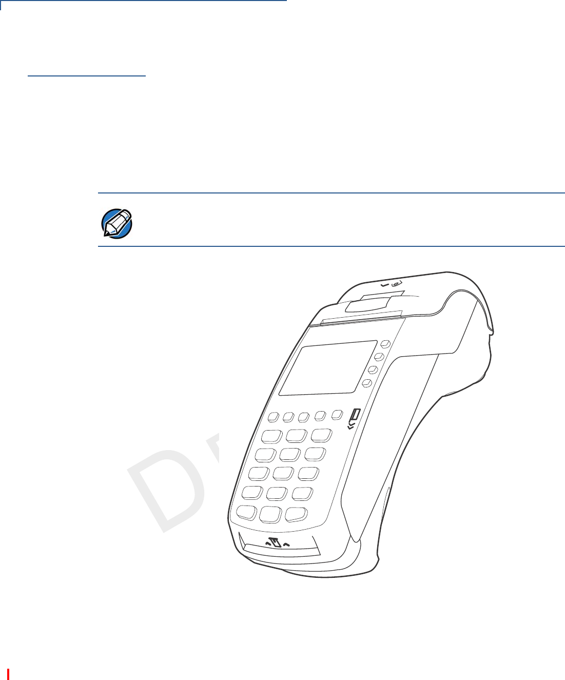
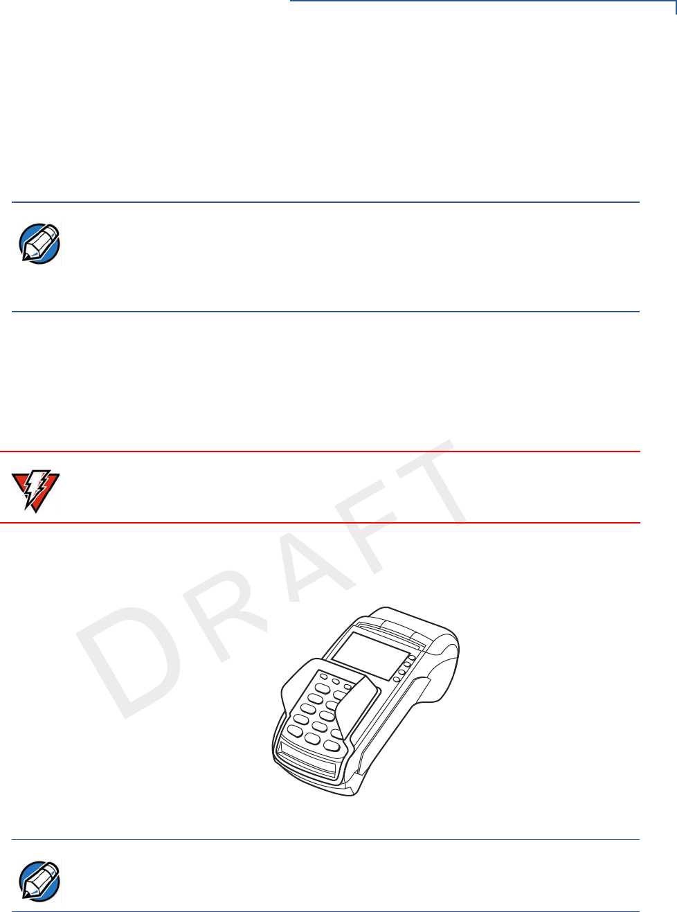
The VX 520 terminal uses a robust, sleek, and highly functional design.
Figure 1 VX 520 Terminal
VX 520 Features and
Benefits
VX 520 terminals provide the right combination of features and functions. This
includes a triple-track magnetic-stripe card reader, landed smart card reader,
integrated PIN pad, a quiet internal thermal printer (ITP). The VX 520 GPRS is a
portable, line- or battery-powered device with added GPRS wireless technology.
Connectivity
•Host USB port
•Client USB port
NOTE
VeriFone ships variants of the VX 520 terminals for different markets. Your
terminal may have a different configuration from the features described in this
section.

TERMINAL OVERVIEW
VX 520 Terminal
VX 520 INSTALLATION GUIDE 11
VERIFO N E
CONF I DENTIAL
TEMPLATE REV F
•RJ-11 port
•RS-232 port
•Ethernet Port
Performance
•400 MHz Processor (CPU)
•Increased memory (128 MB Flash, 32 MB RAM)
•128/64 white backlit LCD
•Fastest encryption/decryption appliance on the market
•Backlit keypad
Security
•Increased Security (PCI 1.3 to PCI 2.0)
•SDA DDA encryption ready
•Leading ECC Performance Benchmark
Form Factor
•The VX 520 is ergonomically designed to fit both the traditional countertop and
hand-over models.
Exceptional Ease of Use
•The bold design is sleek, stylish, and lightweight for conveniently handing the
terminal to the consumer for PIN entry or other input.
•An intuitive ATM-style interface, a large 8-line by 21-character backlit display
with backlit keypad, and extra-size menu prompts, simplify training and reduce
help desk calls.
•The integrated printer simplifies paper loading and reduces paper jams.
•The triple-track, high-coercivity card reader handles most magnetic stripe
cards.
NOTE
The connectivity ports are easily accessible from the underside of the terminal.
NOTE
VeriFone ships variants of the VX 520 terminals for different markets. Your
terminal may have a different configuration from the features described in this
section.

TERMINAL OVERVIEW
VX 520 Terminal
12 VX 520 INSTALLATION GUIDE
VERIFO N E
CONF I DENTIAL
TEMPLATE REV F
Countertop Performance in a Hand-Over Design
•The 32-bit processing and multi-tasking capabilities ensures fast processing of
payment, payment-related, and value-added applications.
•Exceptional display and printer graphics-handling capabilities that quickly
render logos, graphical fonts, and character-based languages.
•The VX 520 series of terminals ensures uncompromising reliability from
VeriFone, the worldwide leader in POS solutions.
•The VX 520 GPRS series meets the needs of TablePAY, DeliveryPAY, and
CarsidePAY markets.
True Multi-Application Capability
•The VX 520 terminal offers 32 MB of RAM, and 128 MB Flash memory, which
supports multiple applications on a single terminal.
•The primary smart card reader and the MSAMs safeguard sensitive financial
data and support multiple smart card schemes.
•VX 520 terminals and SoftPay EMV software are certified for EMV Level 1 and
Level 2 Type approval for smart card solutions. The Verix V or Vx EMV Library
provides development of other EMV-compliant applications.
•The VeriShield security architecture meets published specifications for PCI
PED and provides sophisticated file authentication to prevent execution of
unauthorized software on VX 520 terminals.
Wireless Connectivity (VX 520 GPRS Only)
•Customers are not tied to a fixed location with the VX 520 GPRS terminals –
the point of payment can be almost anywhere.
•“Always-on” wireless connection uses the latest wireless technology (GPRS)
for faster transmission and enhanced compatibility with access points and
routers.
TERMINAL OVERVIEW
VX 520 Sprocket Terminal
VX 520 INSTALLATION GUIDE 13
VERIFO N E
CONF I DENTIAL
TEMPLATE REV F
VX 520 Sprocket
Terminal
This section provides a brief description of the VX 520 Sprocket terminal:
•An optional configuration of the VX 520 replaces the thermal printer with a
sprocket printer, an additional telephone port (RJ-11) and power buttons.
•The VX 520 Sprocket configuration enjoys the same communication and
performance capabilities as the standard VX 520.
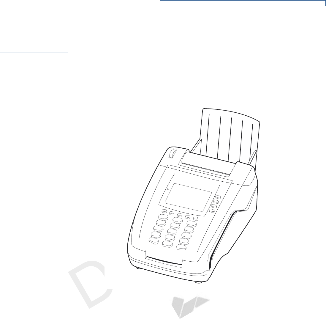
The VX 520 Sprocket terminal uses a robust, highly functional design.
Figure 2 VX 520 Sprocket Terminal
VX 520 Sprocket
Features and
Benefits
VX 520 Sprocket terminals provide the right combination of features and
functions. This includes a triple-track magnetic-stripe card reader, landed smart
card reader, integrated PIN pad, and a dot-matrix impact printer.
Connectivity
•Host USB port
•Client USB port
•RJ-11 ports (1 telco and 1 line)
•RS-232 port
•Ethernet Port

TERMINAL OVERVIEW
VX 520 Sprocket Terminal
14 VX 520 INSTALLATION GUIDE
VERIFO N E
CONF I DENTIAL
TEMPLATE REV F
Performance
•400 MHz Processor (CPU)
•160 MB total memory (128 MB Flash, 32 MB RAM)
•128/64 white backlit LCD
•Fastest encryption/decryption appliance on the market
Security
•PCI PED 2.0 security
Exceptional Ease of Use
•Soft power buttons. Pressing the Enter key for at least three seconds powers
terminal on, while pressing the Cancel key for at least four seconds powers
the terminal off.
•An intuitive ATM-style interface, a large 8-line by 21-character backlit display,
and extra-size menu prompts, simplify training and reduce help desk calls.
•The integrated printer simplifies paper loading and reduces paper jams.
•The triple-track, high-coercivity card reader handles most magnetic stripe
cards.
Countertop Performance with 76 mm Punch Hole Paper Support
•The 32-bit processing and multi-tasking capabilities ensures fast processing of
payment, payment-related, and value-added applications.
•Exceptional display and printer graphics-handling capabilities that quickly
render logos, graphical fonts, and character-based languages.
•The VX 520 Sprocket series of terminals ensures uncompromising reliability
from VeriFone, the worldwide leader in POS solutions.
True Multi-Application Capability
•The VX 520 Sprocket terminal offers 32 MB of RAM, and 128 MB Flash
memory, which supports multiple applications on a single terminal.
•The primary smart card reader and the MSAMs safeguard sensitive financial
data and support multiple smart card schemes.
•VX 520 Sprocket terminals and SoftPay EMV software are certified for EMV
Level 1 and Level 2 Type approval for smart card solutions. The Verix V or VX
EMV Library provides development of other EMV-compliant applications.
•The VeriShield security architecture meets published specifications for PCI
PED and provides sophisticated file authentication to prevent execution of
unauthorized software on VX 520 Sprocket terminals.

VERIFO N E
CONF I DENTIAL
TEMPLATE REV F
VX 520 INSTALLATION GUIDE 15
CHAPTER 2
Terminal Setup
Use this chapter to set up and use your VX 520 terminal. Package contents and
setup procedures may vary for different VX 520 models: The standard VX 520
uses thermal paper rolls while the VX 520 Sprocket uses carbonized paper
sheets. Use the procedures in this section to set up and use your terminal.
•VX 520 Setup
•VX 520 Sprocket Setup

TERMINAL SETUP
VX 520 Setup
16 VX 520 INSTALLATION GUIDE
VERIFO N E
CONF I DENTIAL
TEMPLATE REV F
VX 520 Setup
This section describes the setup procedures for the VX 520 terminal. You will
learn about:
•Selecting Terminal Location
•Unpacking the Shipping Carton
•Examining Terminal Features
•Installing the Smart Battery (VX 520 GPRS Only)
•Establishing Telephone Line Connections
•Installing a Paper Roll in the Printer
•Installing/Replacing MSAM Cards
•Installing/Replacing SIM Card (VX 520 GPRS Only)
•Connecting Optional Devices
•Connecting the Terminal Power Pack
•Charging the Smart Battery (VX 520 GPRS Only)
•Privacy Shield (Optional)
•Using the Smart Card Reader
•Using the Magnetic Card Reader
Selecting Terminal
Location
Use the following guidelines when selecting a location for your VX 520 terminal.
Ease of Use
•Select a location convenient for both merchant and cardholder.
•Select a flat support surface, such as a countertop or table.
•Select a location near a power outlet and a telephone/modem line connection.
For safety, do not string the power cord in a walkway or place it across a
walkway on the floor.
Environmental Factors
•Do not use the terminal where there is high heat, dust, humidity, moisture, or
caustic chemicals or oils.
•Keep the terminal away from direct sunlight and anything that radiates heat,
such as a stove or motor.
•Do not use the terminal outdoors.
CAUTION
The terminal is not waterproof or dustproof, and is intended for indoor use only.
Any damage to the unit from exposure to rain or dust may void any warranty.

TERMINAL SETUP
VX 520 Setup
VX 520 INSTALLATION GUIDE 17
VERIFO N E
CONF I DENTIAL
TEMPLATE REV F
Electrical Considerations
•Avoid using this product during electrical storms.
•Avoid locations near electrical appliances or other devices that cause
excessive voltage fluctuations or emit electrical noise (for example, air
conditioners, electric motors, neon signs, high-frequency or magnetic security
devices, or computer equipment).
•Do not use the terminal near water or in moist conditions.
Unpacking the
Shipping Carton
Open the shipping carton and carefully inspect its contents for possible tampering
or shipping damage. The VX 520 terminal is a secure product and any tampering
may cause the device to cease to function properly.
To unpack the
shipping carton
1Remove and inspect the following items:
•Terminal
•Power pack
•Telephone line cord
•Power cord
2Remove all plastic wrapping from the terminal and other components.
3Remove the clear protective film from the LCD screen.
4Save the shipping carton and packing material for future repacking or moving
the terminal.
CAUTION
Do not use a terminal that has been damaged or tampered with. The VX 520
terminal comes equipped with tamper-evident labels. If a label or component
appears damaged, please notify the shipping company and your VeriFone
representative or service provider immediately.
TERMINAL SETUP
VX 520 Setup
18 VX 520 INSTALLATION GUIDE
VERIFO N E
CONF I DENTIAL
TEMPLATE REV F
Examining Terminal
Features
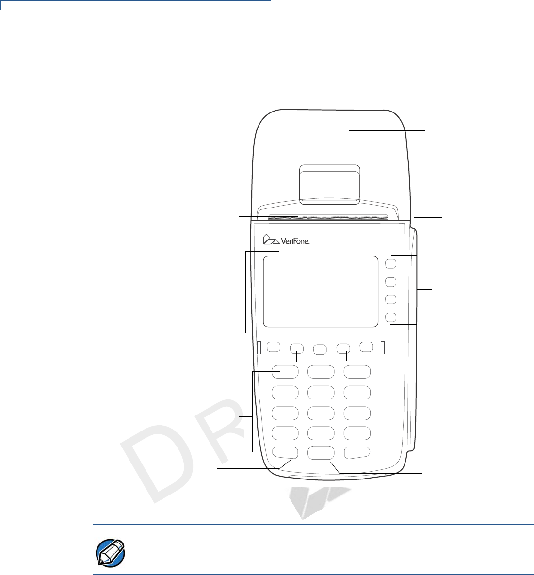
Before you continue the installation process, notice the features of the VX 520
terminal (see Figure 3).
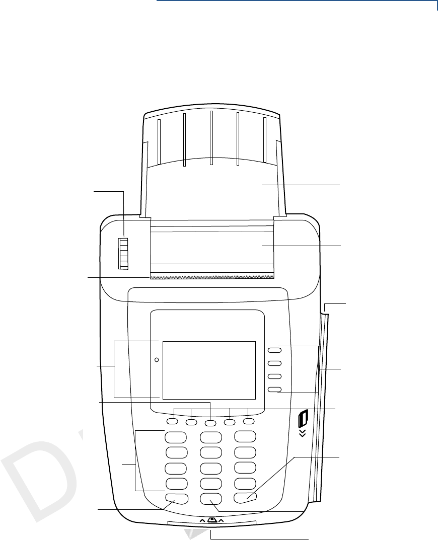
Figure 3 VX 520 Terminal Features (Front Panel)
Front Panel
The front panel includes the following features:
•A terminal display, backlit LCD screen.
•Five types of keys:
aA backlit 12-key, telephone-style keypad.
bFour ATM-style function keys, labeled F1 to F4, to the right of the LCD
screen.
INTERNAL THERMAL
PRINTER
ATM-STYLE
TERMINAL DISPLAY
MAGNETIC
PROGRAMMABLE
ALPHA KEY
TELEPHONE-STYLE
ENTER KEY
SMART CARD READER
FUNCTION KEYS
KEYPAD
CANCEL KEY BACKSPACE/CLEAR KEY
SERRATED METAL
STRIP
FUNCTION KEYS
CARD READER
PRINTER DOOR
LATCH
NOTE
VeriFone ships variants of the VX 520 terminals for different markets. Your
terminal may have a different configuration from the features described in this
section.
TERMINAL SETUP
VX 520 Setup
VX 520 INSTALLATION GUIDE 19
VERIFO N E
CONF I DENTIAL
TEMPLATE REV F
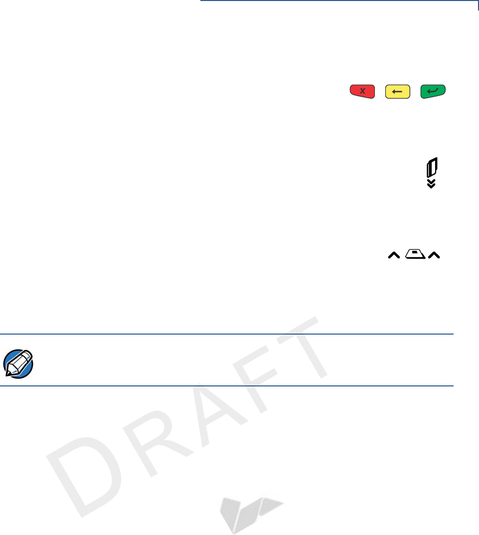
cFour unlabeled, programmable function keys above the keypad.
dThree color-coded function keys below the
keypad (icons at right; from left to right: CANCEL,
BACKSPACE/CLEAR, ENTER).
eAn ALPHA key centered at the top of the keypad.
•A magnetic card reader, built into the right side. The icon at right
shows the proper swipe direction, with the stripe down and facing
inward, toward the keypad.
•The VeriFone logo blue indicator LED indicates power is ON.
•An internal thermal printer.
•A smart card reader, built into the front of the terminal. The
icon shown at right indicates proper card position and
insertion direction.
•Three SAM (security access module) compartments, built into the side of
the terminal. The VX 520 terminal contains MSAM cardholders to support
multiple stored-value card programs or other merchant card requirements.
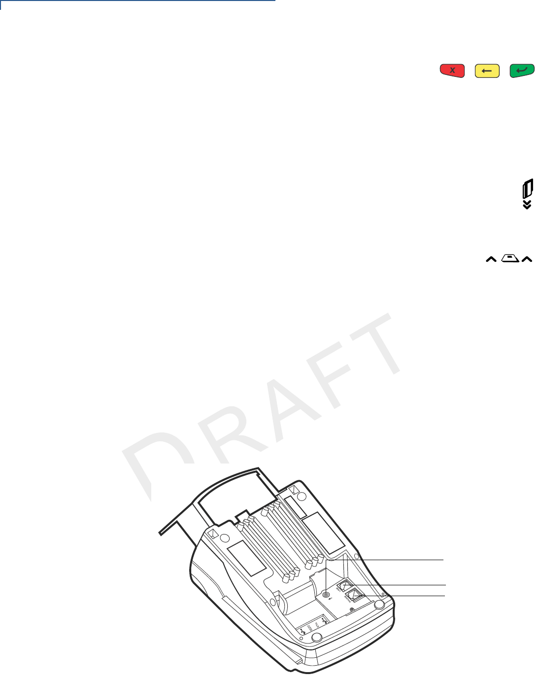
Connection Ports
Turn the terminal upside down and remove the rear cover to view the connection
ports. Notice that the ports are recessed. Different ports provide connections to a
communications line, optional peripheral devices, and the power supply.
NOTE
VeriFone ships variants of the VX 520 terminal for different markets. Your terminal
may have a different configuration. However, the basic processes described in this
guide remain the same, regardless of terminal configuration.
TERMINAL SETUP
VX 520 Setup
VX 520 INSTALLATION GUIDE 21
VERIFO N E
CONF I DENTIAL
TEMPLATE REV F
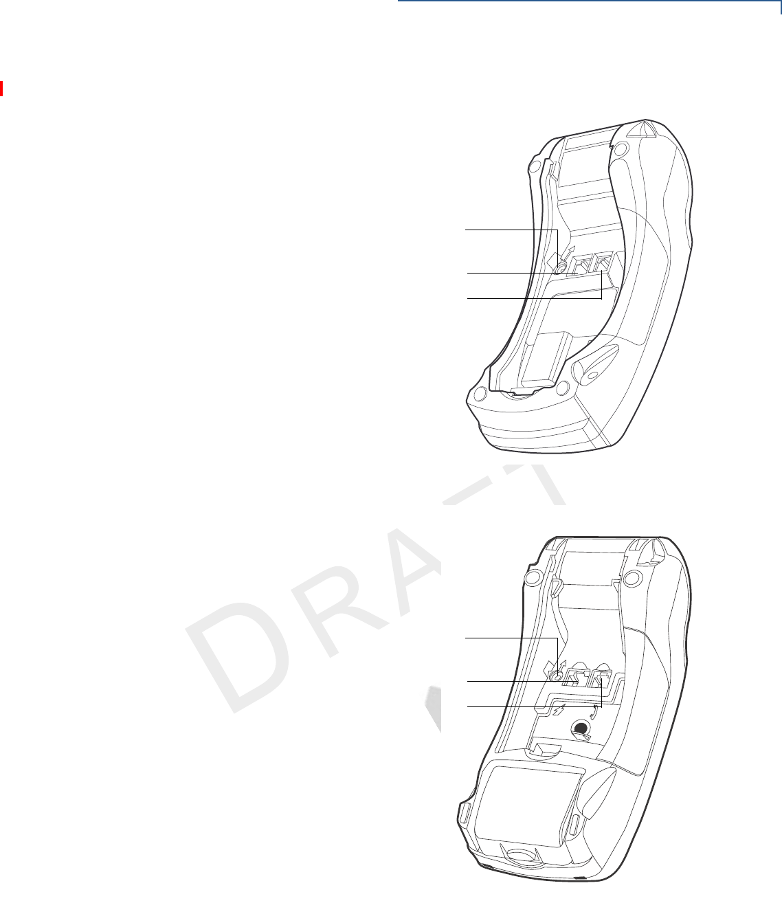
Figure 6 to Figure 8 show the connection ports for the VX 520 terminal.
Figure 6 VX 520 D/E Power and Connection Ports
Figure 7 VX 520 GPRS Power and Connection Ports
POWER PORT
RS-232 SERIAL PORT
RJ-11 TELEPHONE PORT
23
POWER PORT
RS-232 SERIAL PORT
RJ-11 TELEPHONE PORT
TERMINAL SETUP
VX 520 Setup
22 VX 520 INSTALLATION GUIDE
VERIFO N E
CONF I DENTIAL
TEMPLATE REV F
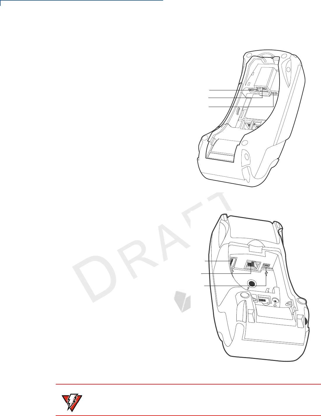
Figure 8 Additional VX 520 D/E Connection Ports
Figure 9 VX 520 GPRS Additional Connection Ports
HOST USB PORT
CLIENT USB PORT
ETHERNET PORT
3
%4(
HOST USB PORT
CLIENT USB PORT
ETHERNET PORT
WARNING
Do not connect the terminal to the power supply until all the peripherals are
attached.

TERMINAL SETUP
VX 520 Setup
VX 520 INSTALLATION GUIDE 23
VERIFO N E
CONF I DENTIAL
TEMPLATE REV F
To use the
connection ports
The connection ports offer multiple connectivity for the VX 520 terminal. Please
refer to the following list of peripheral devices for the connectivity options.
Host USB Port
•PP1000 USB
•Vx810 USB
•Barcode reader
•Biometric reader
•USB flash disk
•USB keyboards
Ethernet Port
•Ethernet cable to router, hub or switch
Client USB Port
•PC
•ECR/Cash register
RJ-11 Port
•Telephone line
RS-232 Port
•PP1000
•Vx810
•PC download cable
•Computer
•ECR
•Check reader
•CTLS reader
•Biometric reader
•Barcode reader
•Keyboard
For information on how to attach peripheral devices, see Connecting Optional
Devices.
TERMINAL SETUP
VX 520 Setup
24 VX 520 INSTALLATION GUIDE
VERIFO N E
CONF I DENTIAL
TEMPLATE REV F
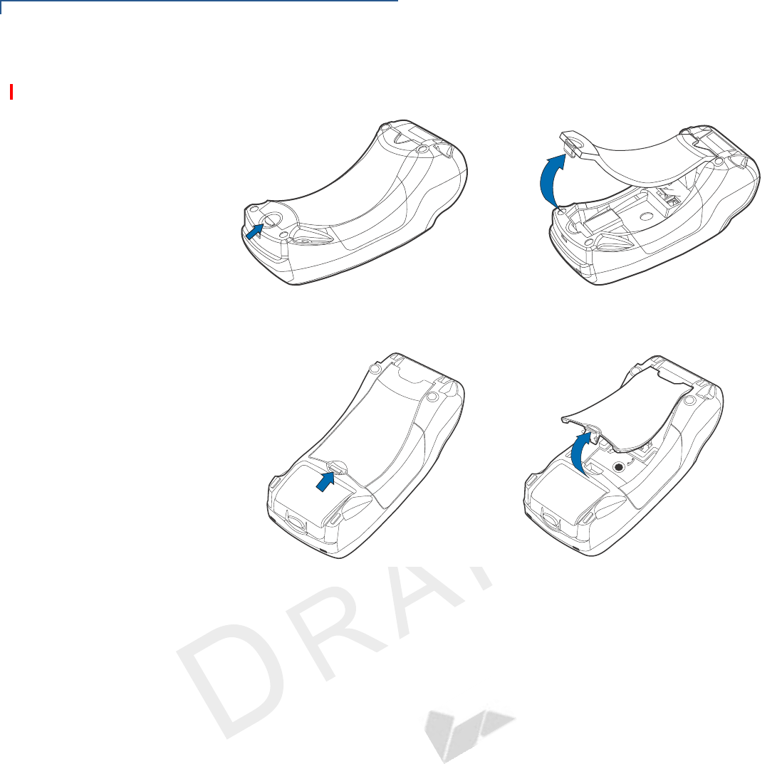
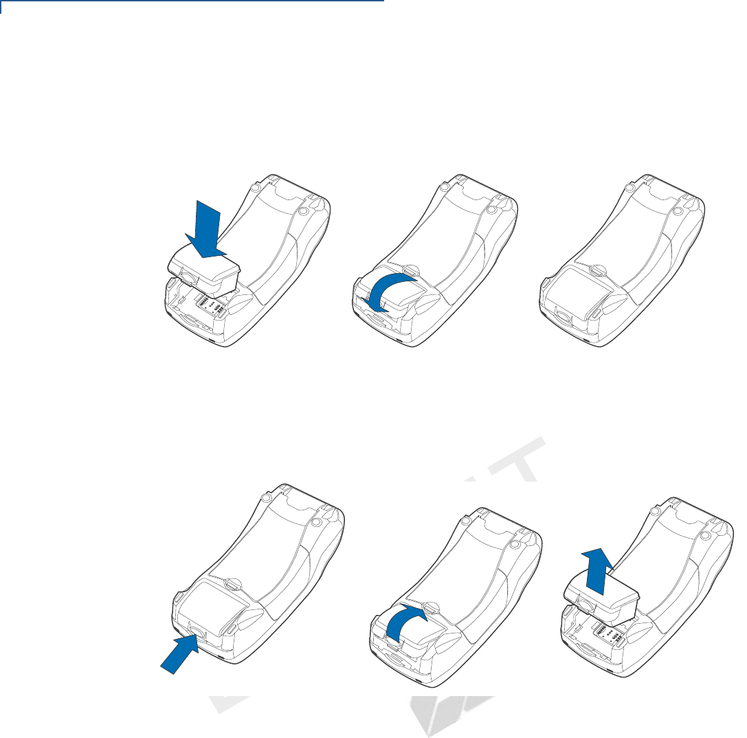
Installing the Smart
Battery (VX 520
GPRS Only)
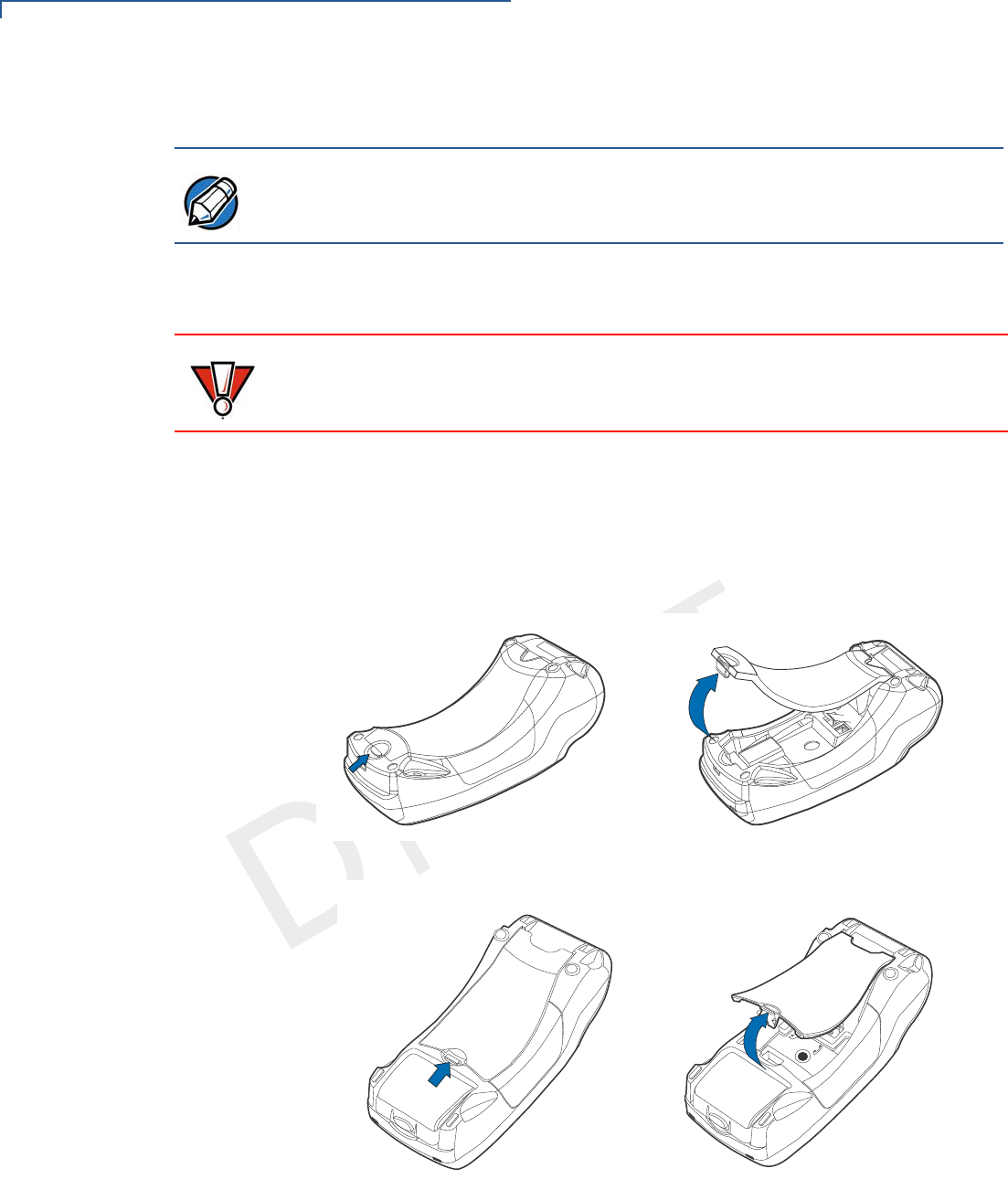
The smart battery fits in a slot on the back of the VX 520 GPRS
terminal. The
locking tab clicks when the battery is in place. The slot is keyed, so that there is
only one way to insert the battery.
Figure 10 Installing the Smart Battery
Removal
To remove the VX 520 GPRS smart battery, press the locking tab and pull the
smart battery from its slot.
Figure 11 Removing the Smart Battery
TERMINAL SETUP
VX 520 Setup
VX 520 INSTALLATION GUIDE 25
VERIFO N E
CONF I DENTIAL
TEMPLATE REV F
Establishing
Telephone Line
Connections
Connect the telephone cord to the communication port on the terminal, then route
it directly to a telephone wall jack (see Figure 12). This is a direct connection and
the line is dedicated to the terminal.
Figure 12 VX 520 D/E Direct Telephone Connection
Figure 13 VX 520 GPRS Direct Telephone Connection
Installing a Paper
Roll in the Printer
Before you can process transactions that require a receipt or record, you must
install paper in the printer.
The VX 520 uses a roll of single-ply, thermal-sensitive paper for either the 38 mm-
or the 49 mm-diameter version.
23
RJ-11
WARNING
To reduce the risk of fire, use only No. 26AWG or larger UL Listed or CSA
Certified Telecommunication Line Cord.
TERMINAL SETUP
VX 520 Setup
26 VX 520 INSTALLATION GUIDE
VERIFO N E
CONF I DENTIAL
TEMPLATE REV F
A pink out-of-paper indicator line appears on the edge of the paper before the end
of the roll. After this line appears, there is enough paper remaining on the roll to
conclude at least one transaction.
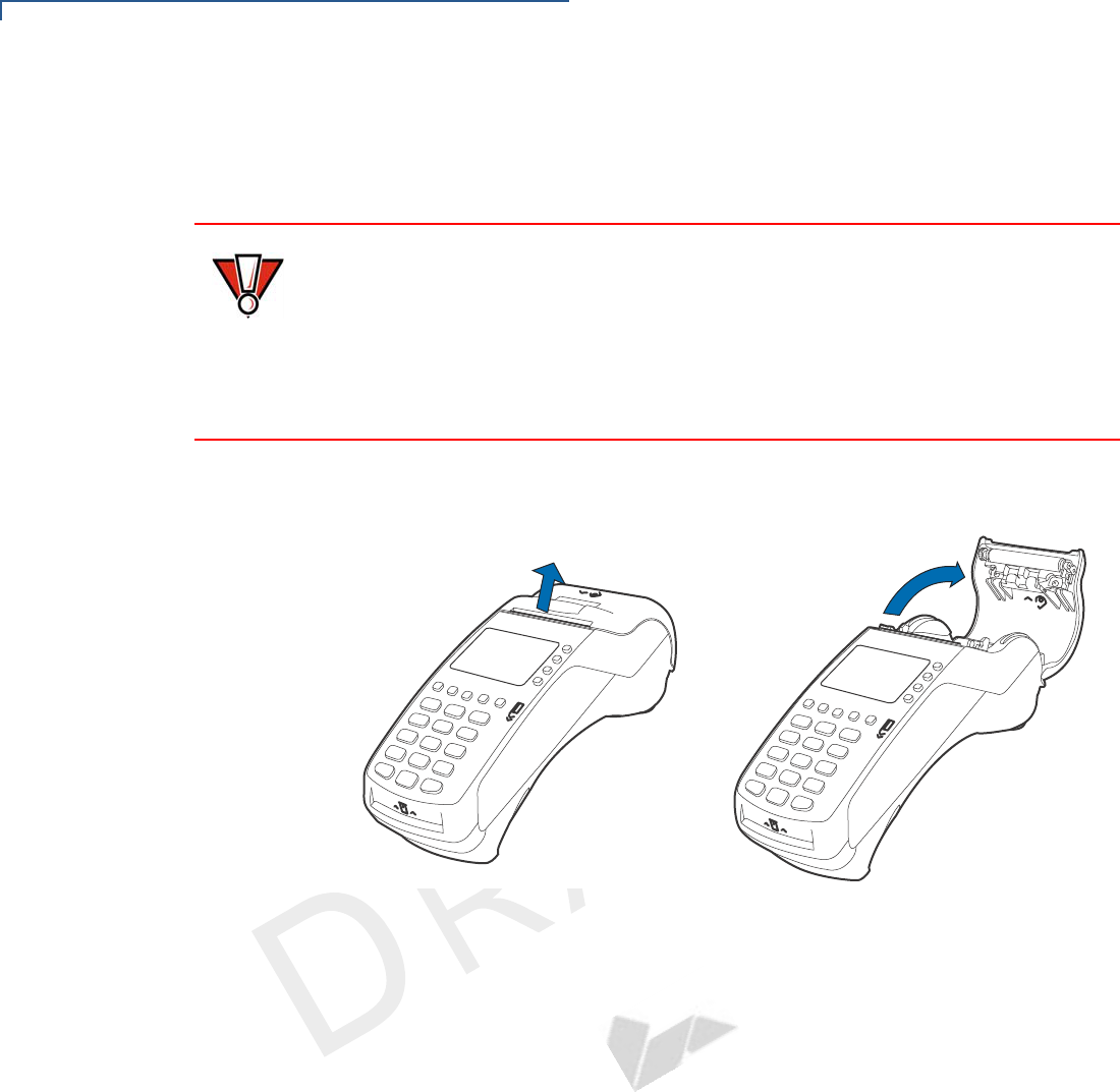
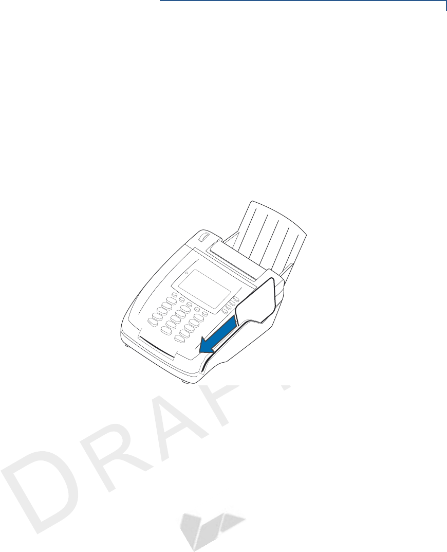
To install a paper roll 1Hook your finger under the latch and lift up to swing the paper roll cover open
(see Figure 14).
Figure 14 Opening the Printer Cover
2Remove any partial roll of paper in the printer tray by lifting it up.
3Loosen the glued leading edge of the new paper roll or remove the protective
strip. Unwind the paper roll past any glue residue.
4Hold the roll so the paper feeds from the bottom of the roll.
5Drop the paper roll into the printer tray.
CAUTION
Poor-quality paper can jam the printer and create excessive paper dust. To order
high-quality VeriFone paper, refer to Accessories and Documentation.
Store thermal paper in a dry, dark area. Handle thermal paper carefully: impact,
friction, temperature, humidity, and oils affect the color and storage
characteristics of the paper.
Never load a roll of paper with folds, wrinkles, tears, or holes at the edges.
TERMINAL SETUP
VX 520 Setup
VX 520 INSTALLATION GUIDE 27
VERIFO N E
CONF I DENTIAL
TEMPLATE REV F
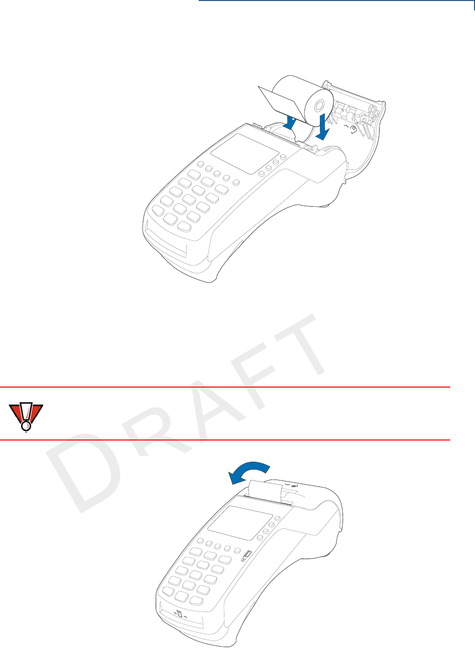
Figure 15 Loading Paper Roll
6Pull paper up past the glue residue.
7Close the paper roll cover by gently pressing directly on the cover until it clicks
shut, allowing a small amount of paper past the glue residue to extend outside
the printer door. (see Figure 16).
Figure 16 Closing Paper Roll Cover
CAUTION
To prevent the paper roll cover from damaging the print roller, always gently press
down on the printer dust cover to close it.
TERMINAL SETUP
VX 520 Setup
28 VX 520 INSTALLATION GUIDE
VERIFO N E
CONF I DENTIAL
TEMPLATE REV F
8Tear the paper off against the serrated metal strip in the printer.
Installing/Replacing
MSAM Cards
When you first receive your VX 520 terminal, you may need to install one or more
MSAM cards or you may need to replace old cards.
To install or replace
MSAMs
1Remove the power cord from the power outlet.
2Place the terminal upside down on a soft, clean surface to protect the display
from scratches.
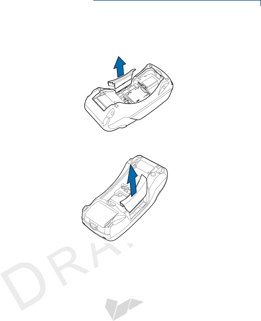
3Press the unlocking button and then lift the rear cover to access the MSAM
cardholder panel.
Figure 17 Opening VX 520 D/E Rear Cover
Figure 18 Opening VX 520 GPRS Rear Cover
NOTE
For paper ordering information, refer to Accessories and Documentation.
CAUTION
Observe standard precautions when handling electrostatically sensitive devices.
Electrostatic discharges can damage this equipment. VeriFone recommends
using a grounded anti-static wrist strap.
23
TERMINAL SETUP
VX 520 Setup
VX 520 INSTALLATION GUIDE 29
VERIFO N E
CONF I DENTIAL
TEMPLATE REV F
4Hold the MSAM cardholder panel, grasp firmly and pull upward to expose the
MSAM slots.
Figure 19 Removing VX 520 D/E MSAM Cover
Figure 20 Removing VX 520 GPRS MSAM Cover
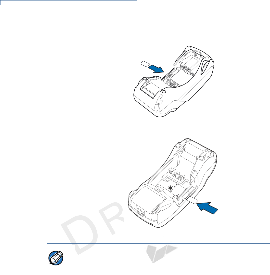
4Remove any previously installed MSAM card by sliding the card from the
MSAM cardholder.
23
%4(
23
TERMINAL SETUP
VX 520 Setup
30 VX 520 INSTALLATION GUIDE
VERIFO N E
CONF I DENTIAL
TEMPLATE REV F
5Install an MSAM card by carefully sliding it into the slot until it is fully inserted.
Figure 21 Installing a VX 520 D/E MSAM Card
Figure 22 Installing a VX 520 GPRS MSAM card
6Close the MSAM cardholder panel, and then replace the terminal rear cover.
Installing/Replacing
SIM Card (VX 520
GPRS Only)
The VX 520 GPRS terminal supports the installation of a SIM (Subscriber Identity
Module) card. Use the following procedure to replace or install a SIM card.
1Place the terminal upside down on a soft, clean surface to protect the display
from scratches.
23
NOTE
Before inserting the MSAM card, position it as shown in Figure 21, with the card’s
gold contacts facing down. The cardholder connector base has an image
resembling the notched corner of an MSAM card to ensure the card is positioned
correctly.
TERMINAL SETUP
VX 520 Setup
VX 520 INSTALLATION GUIDE 31
VERIFO N E
CONF I DENTIAL
TEMPLATE REV F
2Remove the battery.
Figure 23 Removing the Smart Battery
3After removing the battery, you will see the SIM compartment.
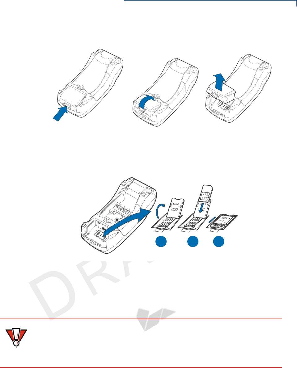
4Insert the SIM into the cardholder.
Figure 24 Inserting SIM Card
5Install the battery.
Connecting
Optional Devices
The VX 520 terminal supports some peripheral devices designed for use with
electronic point-of-sale terminals.
Different terminals support different devices, so for more information about
optional devices, please contact your VeriFone distributor.
Optional Device Connections
The VX 520 terminal has a port that can operate either as a PIN pad port or an
RS-232 port, depending on the power source available.
3)-
3)-
3)-
A B C
23
CAUTION
Before connecting any peripheral device, remove the power cord from the
terminal and ensure that the green indicator LED is not lit. Reconnect the power
cord only after you are finished connecting the peripheral device(s). For complete
information about peripheral installation and use, refer to the user documentation
supplied with those devices.

TERMINAL SETUP
VX 520 Setup
32 VX 520 INSTALLATION GUIDE
VERIFO N E
CONF I DENTIAL
TEMPLATE REV F
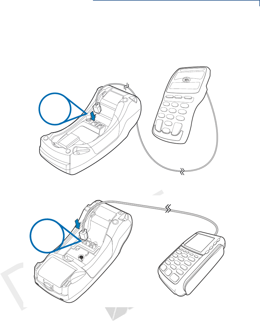
Connecting the PIN
pad or Smart Card
Reader to the VX 520
Use the following procedures to connect a PIN pad or smart card reader.
1Remove the VX 520
terminal rear cover.
2Insert the RJ-45-type connector of the PIN pad or smart card reader into the
port of the peripheral device.
To install a PINpad 101, PINpad 201, or PINpad 1000, position and insert the
grommet to secure the cable connection.
If a cable is not already connected to the smart card reader or PIN pad, insert
the small modular plug on one end of the interface cable into the optional
device’s modular jack.
NOTE
When the VX 520 terminal is powered via the corded power supply, the terminal
provides 4.0 A at 9.3V DC. This power will drive most VeriFone accessories.
Contact your local VeriFone representative for more information.
TERMINAL SETUP
VX 520 Setup
VX 520 INSTALLATION GUIDE 33
VERIFO N E
CONF I DENTIAL
TEMPLATE REV F
3Insert the larger RJ-45-type connector on the other end of the PIN pad cable
into the PIN pad serial port on the terminal. Figure 25 provides an example of
a smart card reader and PIN pad connection to the PIN pad serial port.
Figure 25 VX 520 D/E Sample PIN Pad Connection
Figure 26 VX 520 GPRS Sample PIN Pad Connection
RS-232
23
RS-232
TERMINAL SETUP
VX 520 Setup
34 VX 520 INSTALLATION GUIDE
VERIFO N E
CONF I DENTIAL
TEMPLATE REV F
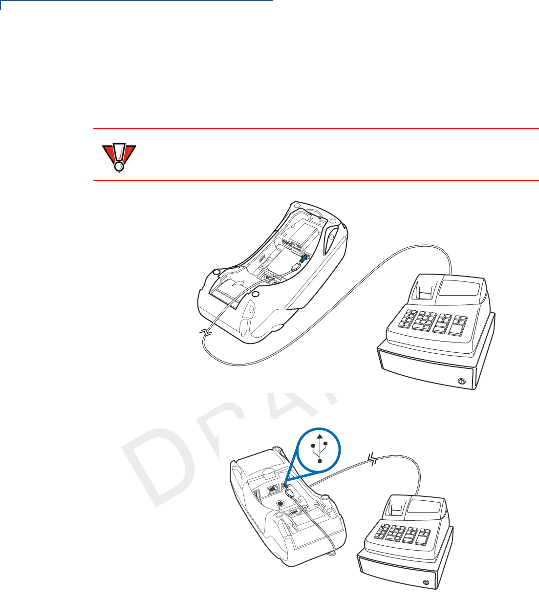
Connecting ECRs to
the VX 520
The VX 520 terminal also supports Electronic Cash Registers (ECR). Contact
your VeriFone representative or visit the online store at www.store.verifone.com
for information on these devices.
Figure 27 provides an example of a peripheral connection to the USB port.
Figure 27 VX 520 D/E Sample ECR Connection
Figure 28 VX 520 GPRS Sample ECR Connection
CAUTION
ECRs require a separate power source. Before connecting a check reader or
similar device, remove the power cord from and ensure that the indicator LED is
not lit.
3
%4(
TERMINAL SETUP
VX 520 Setup
VX 520 INSTALLATION GUIDE 35
VERIFO N E
CONF I DENTIAL
TEMPLATE REV F
External Printers Supported
Although the VX 520 terminal has an internal thermal printer, it may be convenient
to print larger print runs (for example, daily or weekly reports) to an external
printer. The VX 520 terminal supports the VeriFone P250, P350, P900, and P950
external printers. Contact your VeriFone representative or visit the online store at
www.store.verifone.com for information on these devices. External printers
connect through the RS-232 port and require a separate power supply.
Connecting the
Terminal Power
Pack
When you have finished connecting optional peripheral(s), you are ready to
connect the VX 520 terminal to the provided power source.
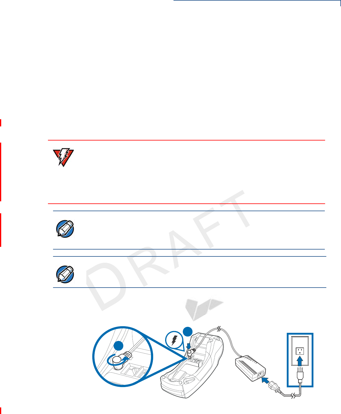
To connect the
terminal power pack
1Remove the terminal rear cover to access the power port.
2Insert the round barrel connector (see Figure 29) into the power port.
Figure 29 VX 520 D/E Power Pack Connection
WARNING
Using an incorrectly rated power supply may damage the terminal or cause it not
to work as specified. Before troubleshooting, ensure that the power supply being
used to power the terminal matches the requirements specified on the bottom of
the terminal. (See Chapter 3, Specifications, for detailed power supply
specifications.) Obtain the appropriately rated power supply before continuing with
troubleshooting.
NOTE
The VX 520 uses an 18-watt wall-mount power supply (VPN: XXXXXXXXX) as a
standard power source. An optional 36-watt power supply (VPN: XXXXXXXXX)
may also be used for all other variants of the VX 520. However, the VX 520
GPRS requires the 36-watt power supply to optimize battery charging.
NOTE
Plugging in the power pack to a power source automatically turns on the terminal.
A
B
TERMINAL SETUP
VX 520 Setup
36 VX 520 INSTALLATION GUIDE
VERIFO N E
CONF I DENTIAL
TEMPLATE REV F
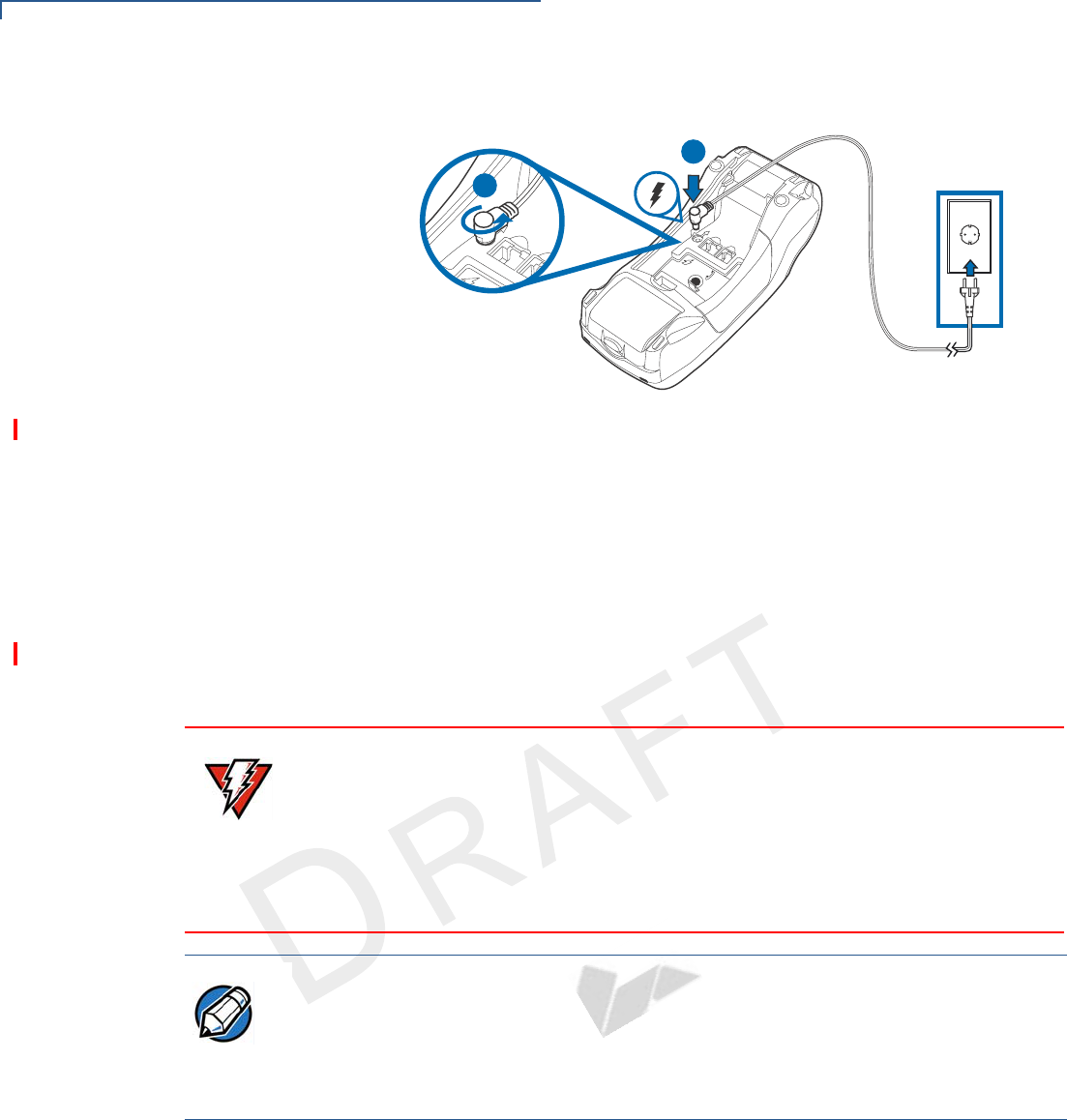
Figure 30 VX 520 GPRS Power Connection
3Rotate the power plug counter-clockwise and flush against the side panel to
lock the plug in place.
4Route the cable in the direction of the arrow above the power port and sling
the cable over the underside of the thermal paper container.
5Close the terminal rear cover.
6Insert the AC power cord into the power pack (for VX 520 D/E models).
7Plug the AC power cord into a wall outlet or powered surge protector.
When the terminal has power, the terminal lights are activated and the LED
indicator remains lit.
If an application is loaded in the terminal, it starts after the initial VeriFone
copyright screen and usually displays a unique copyright screen. If no application
is loaded in the terminal, DOWNLOAD NEEDED appears on screen after the initial
VeriFone copyright screen.
23
23
A
B
WARNING
Do not plug the power pack into an outdoor outlet or operate the terminal
outdoors.
Disconnecting the power during a transaction may cause transaction data files
not yet stored in terminal memory to be lost.
To protect against possible damage caused by lightning strikes and electrical
surges, consider installing a power surge protector.
NOTE
VeriFone recommends connecting wall power in the following order:
1Connect the terminal to the power supply.
2Connect the power supply to the power cord.
3Connect the power cord to the wall outlet.
TERMINAL SETUP
VX 520 Setup
VX 520 INSTALLATION GUIDE 37
VERIFO N E
CONF I DENTIAL
TEMPLATE REV F
Charging the Smart
Battery (VX 520
GPRS Only)
After unpacking your VX 520 GPRS terminal, install the battery and connect the
power pack to the unit for 6 hours or until fully charged.
The smart battery has a safety circuit to protect the Li-ion cells from overcharging
and over-discharging. If the battery is over-discharged, the safety circuit shuts
down the battery. The battery must then be recharged to restore operation.
Battery Life
The VX 520 GPRS smart battery can be charged and discharged hundreds of
times, but will eventually wear out. When operating times are noticeably shorter
than usual, it is time to buy a new battery (see Accessories and Documentation for
ordering information).
Privacy Shield
(Optional)
The privacy shield protects the customers’ PIN entry from being seen by the
cashier or other customers. The illustration shows an example of a VX 520
with
the optional privacy shield.
Figure 31 Optional Privacy Shield
NOTE
The VX 520 GPRS terminal automatically shuts off when the smart battery
reaches the critically low charge state. If this occurs, the smart battery must be
recharged for a minimum of 1/2 hour before it can power the terminal. It may take
several recharge attempts to reset the safety circuit when charging a smart
battery that has been discharged below this critical state.
WARNING
Do not dispose of batteries in a fire. Li-ion batteries must be recycled or disposed
of properly. Do not dispose of Li-ion batteries in municipal waste sites.
NOTE
Merchants who install the terminal without the privacy shield must ensure the
cardholder’s privacy when entering his PIN by positioning the terminal away from
open view.
TERMINAL SETUP
VX 520 Setup
38 VX 520 INSTALLATION GUIDE
VERIFO N E
CONF I DENTIAL
TEMPLATE REV F
Using the Smart
Card Reader
The smart card transaction procedure may vary from one application to another.
Verify the procedure with your application provider before performing a smart card
transaction.
To conduct a smart
card transaction
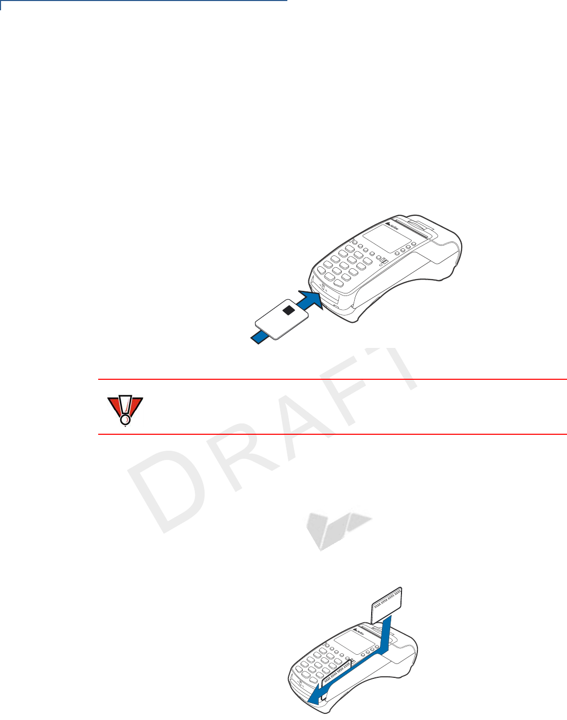
1Position a smart card with the contacts facing upward (see Figure 32).
2Insert the smart card into the smart card reader slot in a smooth, continuous
motion until it seats firmly.
3Remove the card only when the application indicates the transaction is
complete.
Figure 32 Inserting a Smart Card
Using the Magnetic
Card Reader
The VX 520 terminal supports credit or debit card transactions.
To conduct a credit or
debit card transaction
1Position a magnetic card with the stripe in the card reader and facing inward,
toward the keypad.
2To ensure a proper read of the magnetic swipe card, the user should insert the
magnetic card from the top of the unit, as shown in Figure 33.
3Swipe the card through the magnetic card reader.
Figure 33 Using the Magnetic Card Reader
CAUTION
Leave the smart card in the card reader until the transaction is complete.
Premature card removal will invalidate the transaction.

TERMINAL SETUP
VX 520 Sprocket Setup
VX 520 INSTALLATION GUIDE 39
VERIFO N E
CONF I DENTIAL
TEMPLATE REV F
VX 520 Sprocket
Setup
This section describes the setup procedures for the VX 520 Sprocket terminal.
You will learn about:
•Selecting Terminal Location
•Unpacking the Shipping Carton
•Examining Terminal Features
•Establishing Telephone and Line Connections
•Installing Paper in the Tray
•Installing/Replacing MSAM Cards
•Connecting Optional Devices
•Connecting the Terminal Power Pack
•Privacy Shield (Optional)
•Using the Smart Card Reader
•Using the Magnetic Card Reader
Selecting Terminal
Location
Use the following guidelines when selecting a location for your VX 520 Sprocket
terminal.
Ease of Use
•Select a location convenient for both merchant and cardholder.
•Select a flat support surface, such as a countertop or table.
•Select a location near a power outlet and a telephone/modem line connection.
For safety, do not string the power cord in a walkway or place it across a
walkway on the floor.
Environmental Factors
•Do not use the terminal where there is high heat, dust, humidity, moisture, or
caustic chemicals or oils.
•Keep the terminal away from direct sunlight and anything that radiates heat,
such as a stove or motor.
•Do not use the terminal outdoors.
CAUTION
The terminal is not waterproof or dustproof, and is intended for indoor use only.
Any damage to the unit from exposure to rain or dust may void any warranty.

TERMINAL SETUP
VX 520 Sprocket Setup
40 VX 520 INSTALLATION GUIDE
VERIFO N E
CONF I DENTIAL
TEMPLATE REV F
Electrical Considerations
•Avoid using this product during electrical storms.
•Avoid locations near electrical appliances or other devices that cause
excessive voltage fluctuations or emit electrical noise (for example, air
conditioners, electric motors, neon signs, high-frequency or magnetic security
devices, or computer equipment).
•Do not use the terminal near water or in moist conditions.
Unpacking the
Shipping Carton
Open the shipping carton and carefully inspect its contents for possible tampering
or shipping damage. The VX 520 Sprocket terminal is a secure product and any
tampering may cause the device to cease to function properly.
To unpack the
shipping carton
1Remove and inspect the following items:
•Terminal
•Power pack
•Telephone line cord
•Power cord
2Remove all plastic wrapping from the terminal and other components.
3Remove the clear protective film from the LCD screen.
4Save the shipping carton and packing material for future repacking or moving
the terminal.
CAUTION
Do not use a terminal that has been damaged or tampered with. The VX 520
Sprocket terminal comes equipped with tamper-evident labels. If a label or
component appears damaged, please notify the shipping company and your
VeriFone representative or service provider immediately.
TERMINAL SETUP
VX 520 Sprocket Setup
VX 520 INSTALLATION GUIDE 41
VERIFO N E
CONF I DENTIAL
TEMPLATE REV F
Examining Terminal
Features
Before you continue the installation process, notice the features of the VX 520
Sprocket terminal (see Figure 34).
Figure 34 VX 520 Sprocket Terminal Features (Front Panel)
Front Panel
The front panel includes the following features:
•A terminal display, backlit LCD screen.
•Five types of keys:
aA 12-key, telephone-style keypad.
bFour ATM-style function keys, labeled F1 to F4, to the right of the LCD
screen.
cFour unlabeled, programmable function keys above the keypad.
PRINTER
ATM-STYLE
TERMINAL
MAGNETIC
PROGRAMMABLE
ALPHA KEY
TELEPHONE-STYLE
ENTER KEY
SMART CARD READER
FUNCTION KEYS
KEYPAD
CANCEL KEY
BACKSPACE/CLEAR KEY
SERRATED
FUNCTION KEYS
CARD READER
PAPER TRAY
PAPER
LOADER
SPROCKET
(POWER OFF
METAL STRIP
DISPLAY
(POWER ON
BUTTON)
BUTTON)
TERMINAL SETUP
VX 520 Sprocket Setup
42 VX 520 INSTALLATION GUIDE
VERIFO N E
CONF I DENTIAL
TEMPLATE REV F
dThree color-coded function keys below the
keypad (icons at right; from left to right: CANCEL,
BACKSPACE/CLEAR, ENTER). The Cancel key
also acts as the Power Off button, while the Enter key also functions as the
Power On button. Press the Enter key for at least three seconds to power
on the terminal, and press the Cancel key for at least four seconds to
power the terminal off
eAn ALPHA key centered at the top of the keypad.
•A magnetic card reader, built into the right side. The icon at right
shows the proper swipe direction, with the stripe down and facing
inward, toward the keypad.
•An internal, sprocket-fed, serial dot-matrix printer.
•A smart card reader, built into the front of the terminal. The
icon shown at right indicates proper card position and insertion
direction.
•Three SAM (security access module) compartments, built into the side of
the terminal. The VX 520 Sprocket terminal contains MSAM cardholders to
support multiple stored-value card programs or other merchant card
requirements.
Connection Ports
Turn the terminal upside down to view the connection ports. Notice that the ports
are recessed. Different ports provide connections to a communications line,
optional peripheral devices, and the power supply.
Figure 35 and Figure 36 show the connection ports for the VX 520 Sprocket
terminal.
Figure 35 VX 520 Sprocket Power and Connection Ports
POWER PORT
RJ-11 (LINE)
RJ-11 (PHONE)
TERMINAL SETUP
VX 520 Sprocket Setup
VX 520 INSTALLATION GUIDE 43
VERIFO N E
CONF I DENTIAL
TEMPLATE REV F
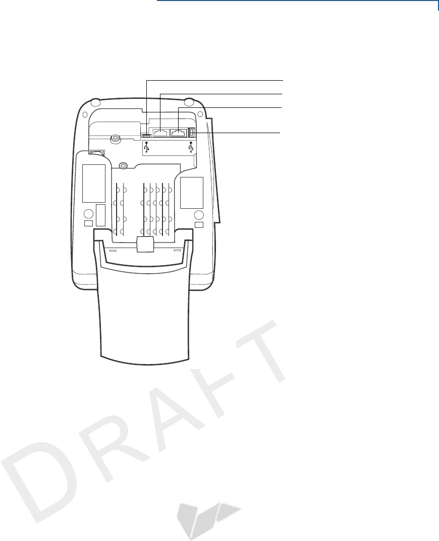
Figure 36 VX 520 Sprocket Additional Connection Ports
To use the
connection ports
The connection ports offer multiple connectivity for the VX 520 Sprocket terminal.
Please refer to the following list of peripheral devices for the connectivity options.
Host USB Port
•PP1000 USB
•Vx810 USB
•Barcode reader
•Biometric reader
•USB flash disk
•USB keyboards
Ethernet Port
•Ethernet cable to router, hub or switch
Client USB Port
•PC
•ECR/Cash register
RJ-11 Ports
•Telephone
E
NO
HP
232SR
H
T
E
CLIENT USB PORT
RS-232 PORT
RJ-45 (ETHERNET) PORT
HOST USB PORT

TERMINAL SETUP
VX 520 Sprocket Setup
44 VX 520 INSTALLATION GUIDE
VERIFO N E
CONF I DENTIAL
TEMPLATE REV F
•Line
RS-232 Port
•PP1000
•Vx810
•PC download cable
•Computer
•ECR
•Check reader
•CTLS reader
•Biometric reader
•Barcode reader
•Keyboard
For information on how to attach peripheral devices, see Connecting Optional
Devices.
TERMINAL SETUP
VX 520 Sprocket Setup
VX 520 INSTALLATION GUIDE 45
VERIFO N E
CONF I DENTIAL
TEMPLATE REV F
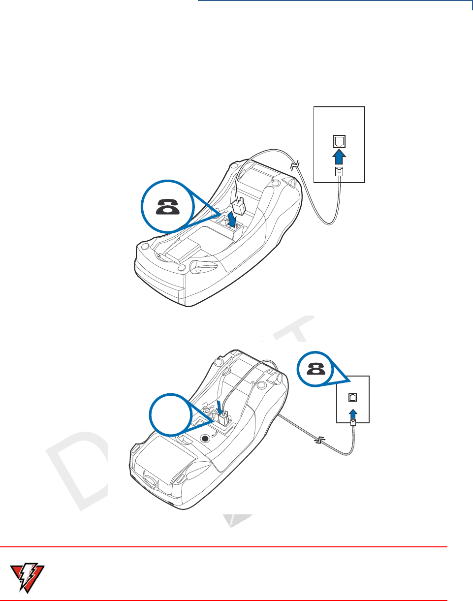
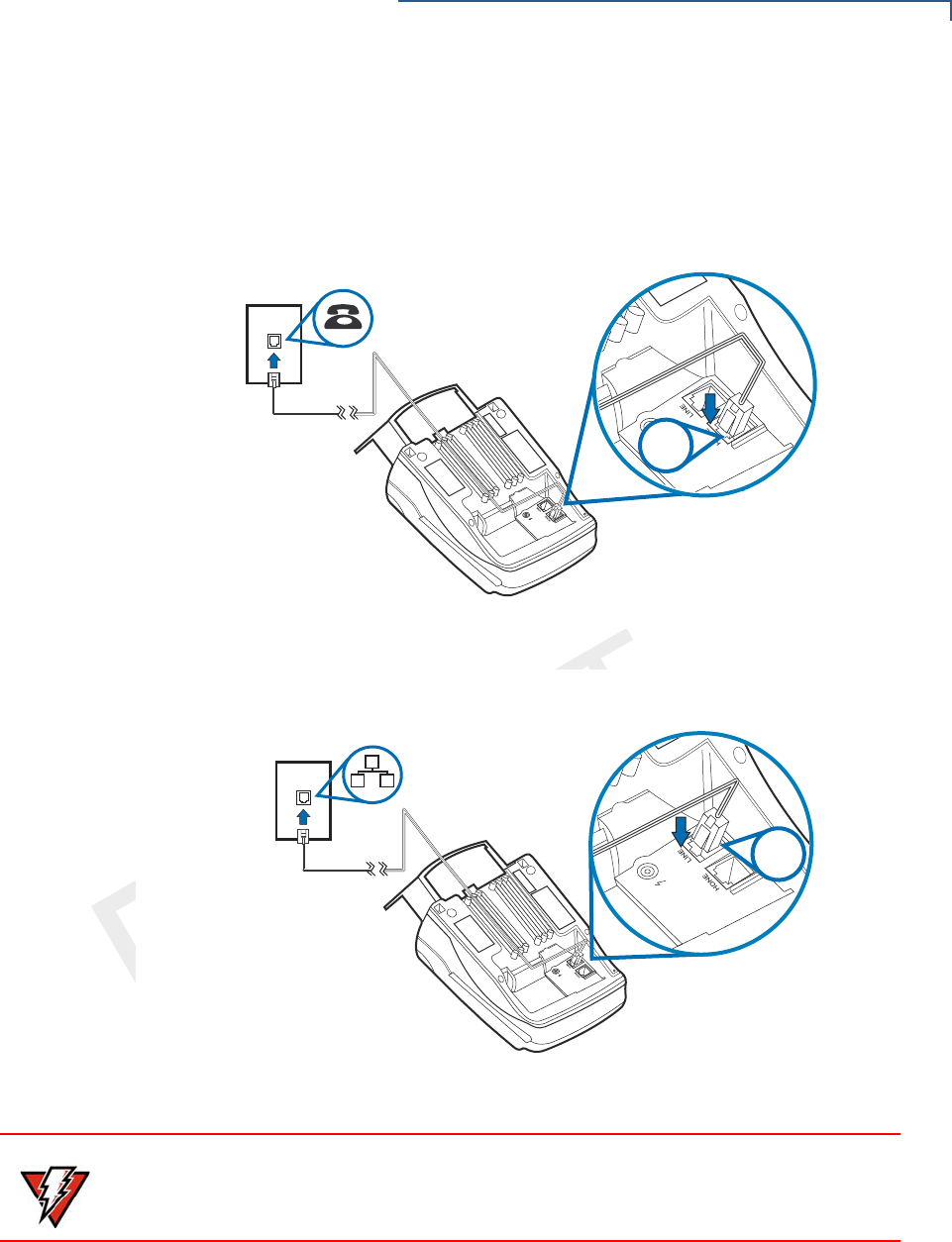
Establishing
Telephone and Line
Connections
Connect the telephone cord to the communication port on the terminal, then route
it directly to a telephone wall jack. Connect the telephone to the phone port
(see Figure 37 and Figure 38). The communications connection is dedicated to
the terminal.
Figure 37 VX 520 Sprocket Telephone Connection
Figure 38 VX 520 Sprocket Line Connection
RJ11
RJ11
WARNING
To reduce the risk of fire, use only No. 26AWG or larger UL Listed or CSA
Certified Telecommunication Line Cord.
TERMINAL SETUP
VX 520 Sprocket Setup
46 VX 520 INSTALLATION GUIDE
VERIFO N E
CONF I DENTIAL
TEMPLATE REV F
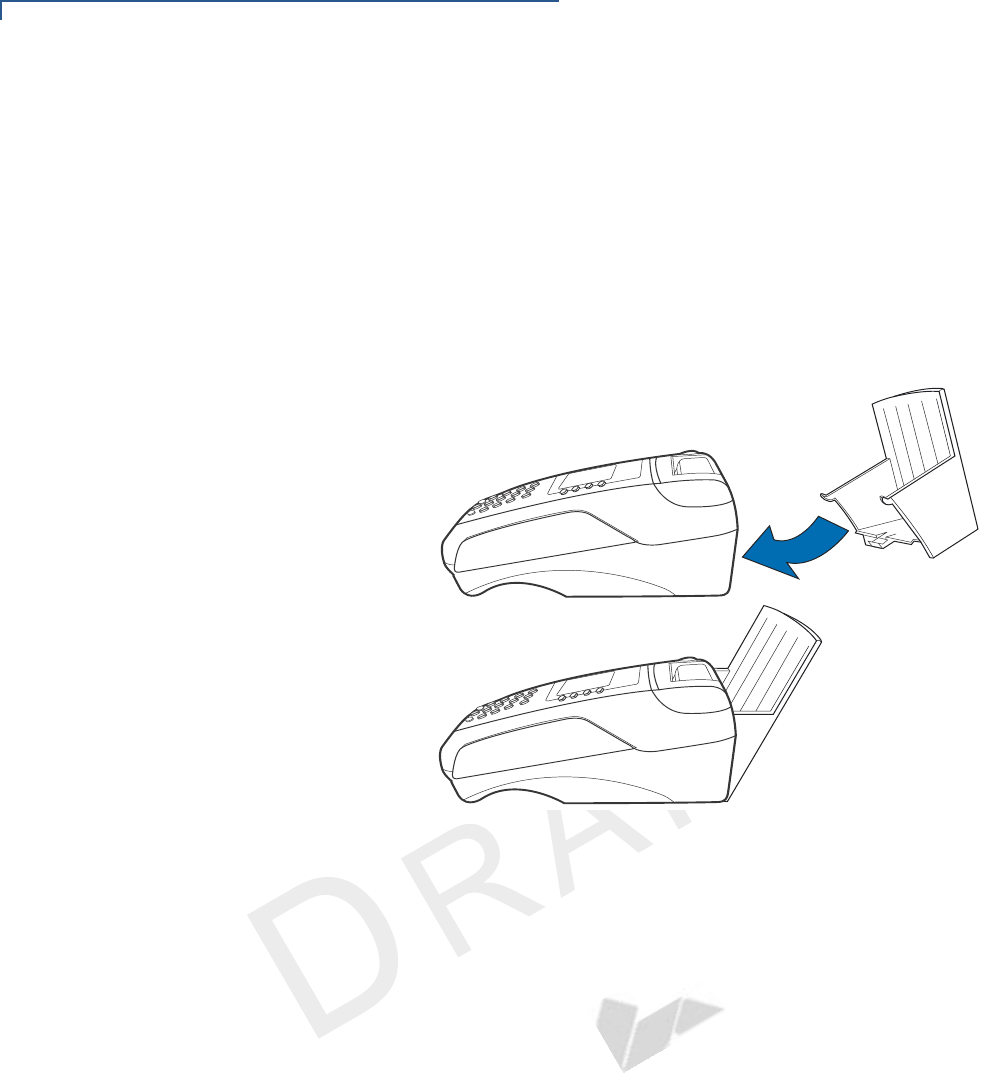
Installing Paper Tray
The VX 520 Sprocket terminal uses 76 mm carbonized paper sheets. This type of
paper requires an external-mounted paper tray. Use the following procedure to
install the paper tray for the VX 520 Sprocket terminal:
To install the paper
tray
1Align the slots with the paper tray clasps.
2Slide the paper tray into the rear of the terminal.
3Hook the clasps into the slots to secure the tray and snap the lock on the
lower end of the tray.
Figure 39 Attaching Paper Tray
TERMINAL SETUP
VX 520 Sprocket Setup
VX 520 INSTALLATION GUIDE 47
VERIFO N E
CONF I DENTIAL
TEMPLATE REV F
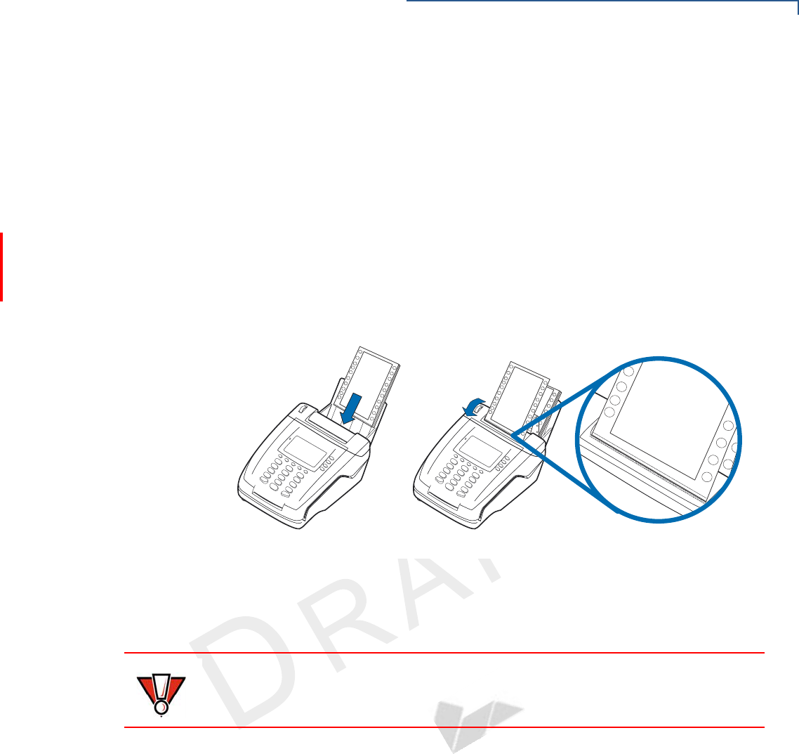
Installing Paper in
the Tray
Before you can process transactions that require a receipt or record, you must
install paper in the printer tray.
The VX 520 Sprocket uses a stack of double-ply carbonized paper.
To install a paper
stack
1Remove any partial stack of paper in the printer tray.
2Place the new stack of paper into the tray
3Feed the first sheet of paper into the sprocket printer.
4Slowly turn the sprocket paper loader downwards until the leading edge of
the paper or the perforation edge of the paper aligns with the tear bar.
Figure 40 Loading Paper Stack
Installing/Replacing
MSAM Cards
When you first receive your VX 520 Sprocket terminal, you may need to install one
or more MSAM cards or you may need to replace old cards.
To install or replace
MSAMs
1Remove the power cord from the power outlet.
2Place the terminal upside down on a soft, clean surface to protect the display
from scratches.
CAUTION
Observe standard precautions when handling electrostatically sensitive devices.
Electrostatic discharges can damage this equipment. VeriFone recommends
using a grounded anti-static wrist strap.
TERMINAL SETUP
VX 520 Sprocket Setup
48 VX 520 INSTALLATION GUIDE
VERIFO N E
CONF I DENTIAL
TEMPLATE REV F
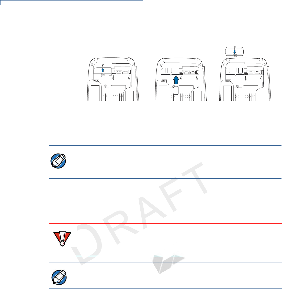
4Unscrew the MSAM cardholder cover and pull the cover away to expose the
MSAM slots.
Figure 41 Installing or Replacing MSAMs
5Remove any previously installed MSAM card by sliding the card from the
MSAM cardholder.
6Install an MSAM card by carefully sliding it into the slot until it is fully inserted.
7Return and secure the MSAM cardholder cover with the screw.
Connecting
Optional Devices
The VX 520 Sprocket terminal supports some peripheral devices designed for use
with electronic point-of-sale terminals.
Different terminals support different devices, so for more information about
optional devices, please contact your VeriFone distributor.
Optional Device Connections
The VX 520 Sprocket terminal has a port that can operate either as a PIN pad port
or an RS-232 port, depending on the power source available.
ENOHP
232SR
HTE
ENO
HP
232SR
H
T
E
ENOH
P
232SR
H
T
E
NOTE
Before inserting the MSAM card, position it as shown in Figure 41, with the card’s
gold contacts facing down. The cardholder connector base has an image
resembling the notched corner of an MSAM card to ensure the card is positioned
correctly.
CAUTION
Before connecting any peripheral device, remove the power cord from the
terminal. Reconnect the power cord only after you are finished connecting the
peripheral device(s). For complete information about peripheral installation and
use, refer to the user documentation supplied with those devices.
NOTE
When the VX 520 Sprocket terminal is powered via the corded power supply, the
terminal provides 1.7 A at 24V DC. This power will drive most VeriFone
accessories. Contact your local VeriFone representative for more information.
TERMINAL SETUP
VX 520 Sprocket Setup
VX 520 INSTALLATION GUIDE 49
VERIFO N E
CONF I DENTIAL
TEMPLATE REV F
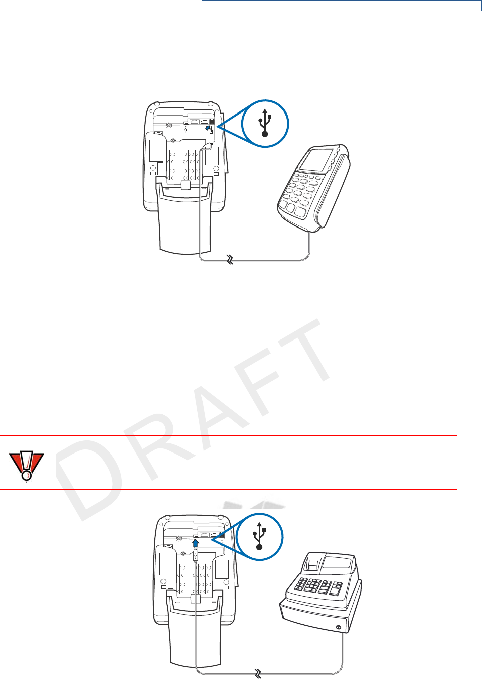
Connecting the PIN
pad or Smart Card
Reader to the VX 520
Sprocket
Use the following procedures to connect a PIN pad to the VX 520 Sprocket.
Figure 42 provides an example of a peripheral connection to the Host USB port
Figure 42 VX 520 Sprocket Sample PIN pad Connection
1Turn the terminal upside down to access the connection ports.
2Insert the USB connector of the PIN pad into the USB port of the VX 520
Sprocket.
Connecting ECRs to
the VX 520 Sprocket
The VX 520 Sprocket terminal also supports Electronic Cash Registers (ECR).
Contact your VeriFone representative or visit the online store at
www.store.verifone.com for information on these devices.
Figure 43 provides an example of a peripheral connection to the Client USB port.
Figure 43 VX 520 Sprocket Sample ECR Connection
ENO
HP
232SR
HTE
CAUTION
ECRs require a separate power source. Before connecting a check reader or
similar device, remove the power cord from and ensure that the indicator LED is
not lit.
E
NO
H
P
232SR
H
T
E
TERMINAL SETUP
VX 520 Sprocket Setup
50 VX 520 INSTALLATION GUIDE
VERIFO N E
CONF I DENTIAL
TEMPLATE REV F
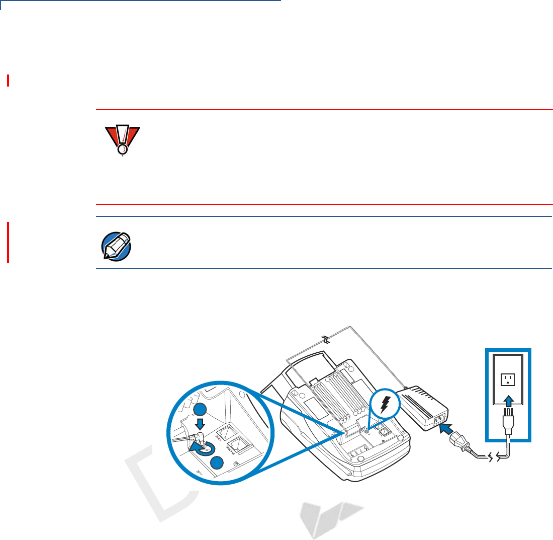
Connecting the
Terminal Power
Pack
When you have finished connecting optional peripheral(s), you are ready to
connect the VX 520 Sprocket terminal to the provided power source.
To connect the
terminal power pack
1Turn the terminal upside down to access the power port.
2Insert the round barrel connector (see Figure 44) into the power port.
Figure 44 VX 520 Sprocket Power Pack Connection
3Rotate the power plug counter-clockwise and flush against the side panel to
lock the plug in place.
4Route the cable in one of the channels on the underside of the terminal.
5Insert the AC power cord into the power pack.
CAUTION
Using an incorrectly rated power supply may damage the terminal or cause it not
to work as specified. Before troubleshooting, ensure that the power supply being
used to power the terminal matches the requirements specified on the bottom of
the terminal. (See Chapter 3, Specifications, for detailed power supply
specifications.) Obtain the appropriately rated power supply before continuing
with troubleshooting.
NOTE
The VX 520 uses an 18-watt wall-mount power supply (VPN: XXXXXXXXX) as a
standard power source. An optional 36-watt power supply (VPN: XXXXXXXXX)
may also be used for all other variants of the VX 520.
1
2

TERMINAL SETUP
VX 520 Sprocket Setup
VX 520 INSTALLATION GUIDE 51
VERIFO N E
CONF I DENTIAL
TEMPLATE REV F
6Plug the AC power cord into a wall outlet or powered surge protector.
7Press the Enter key for at least three seconds to power on the terminal.
If an application is loaded in the terminal, it starts after the initial VeriFone
copyright screen and usually displays a unique copyright screen. If no application
is loaded in the terminal, DOWNLOAD NEEDED appears on screen after the initial
VeriFone copyright screen.
Privacy Shield
(Optional)
The privacy shield protects the customers’ PIN entry from being seen by the
cashier or other customers.
WARNING
Do not plug the power pack into an outdoor outlet or operate the terminal
outdoors.
Disconnecting the power during a transaction may cause transaction data files
not yet stored in terminal memory to be lost.
To protect against possible damage caused by lightning strikes and electrical
surges, consider installing a power surge protector.
NOTE
VeriFone recommends connecting wall power in the following order:
1Connect the terminal to the power supply.
2Connect the power supply to the power cord.
3Connect the power cord to the wall outlet.
NOTE
Merchants who install the terminal without the privacy shield must ensure the
cardholder’s privacy when entering his PIN by positioning the terminal away from
open view.
TERMINAL SETUP
VX 520 Sprocket Setup
52 VX 520 INSTALLATION GUIDE
VERIFO N E
CONF I DENTIAL
TEMPLATE REV F
Using the Smart
Card Reader
The smart card transaction procedure may vary from one application to another.
Verify the procedure with your application provider before performing a smart card
transaction.
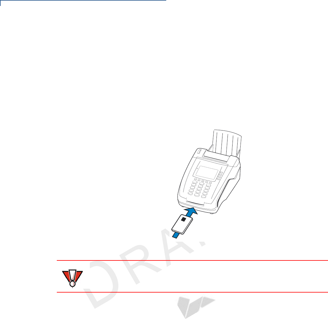
To conduct a smart
card transaction
1Position a smart card with the contacts facing upward (see Figure 45).
2Insert the smart card into the smart card reader slot in a smooth, continuous
motion until it seats firmly.
3Remove the card only when the application indicates the transaction is
complete.
Figure 45 Inserting a Smart Card
CAUTION
Leave the smart card in the card reader until the transaction is complete.
Premature card removal will invalidate the transaction.
TERMINAL SETUP
VX 520 Sprocket Setup
VX 520 INSTALLATION GUIDE 53
VERIFO N E
CONF I DENTIAL
TEMPLATE REV F
Using the Magnetic
Card Reader
The VX 520 Sprocket terminal supports credit or debit card transactions.
To conduct a credit or
debit card transaction
1Position a magnetic card with the stripe in the card reader and facing inward,
toward the keypad.
2To ensure a proper read of the magnetic swipe card, the user should insert the
magnetic card from the top of the unit, as shown in Figure 46.
3Swipe the card through the magnetic card reader.
Figure 46 Using the Magnetic Card Reader
xxxx-xxxx
-
xxxx-xxx
x

TERMINAL SETUP
VX 520 Sprocket Setup
54 VX 520 INSTALLATION GUIDE
VERIFO N E
CONF I DENTIAL
TEMPLATE REV F


SPECIFICATIONS
VX 520 Specifications
56 VX 520 INSTALLATION GUIDE
VERIFO N E
CONF I DENTIAL
TEMPLATE REV F
VX 520
Specifications
Power
VX 520 terminal: 9.3V DC; 4.0 A
DC Power Pack
UL, ITE listed, LPS power supply:
aInput rated: 100 - 240V AC, 50/60 Hz
bOutput rated: 9.3V DC 4.0 A
Barrel connector polarity:
Temperature
•Operating temperature: 0° to 40° C (32° to 104° F)
•Storage temperature: -30° to + 60° C (-22° to 140° F)
•Relative humidity: 5% to 85%; no condensation
External
Dimensions
•Length: 203 mm (7.9 in)
•Width: 87 mm (3.4 in)
NOTE
The VX 520 uses an 18-watt wall-mount power supply (VPN: XXXXXXXXX) as a
standard power source. An optional 36-watt power supply (VPN: XXXXXXXXX)
may also be used for all other variants of the VX 520. However, the VX 520
GPRS requires the 36-watt power supply to optimize battery charging.
+
–

SPECIFICATIONS
VX 520 Sprocket Specifications
VX 520 INSTALLATION GUIDE 57
VERIFO N E
CONF I DENTIAL
TEMPLATE REV F
VX 520 Sprocket
Specifications
Power
VX 520 Sprocket terminal: 24V DC; 1.7 A
DC Power Pack
UL, ITE listed, LPS power supply:
aInput rated: 100 - 240V AC, 50/60 Hz
bOutput rated: 24V DC; 1.7 A
Barrel connector polarity:
Temperature
•Operating temperature: 0° to 40° C (32° to 104° F)
•Storage temperature: -25° to + 60° C (-13° to 140° F)
•Relative humidity: 5% to 90%; no condensation
External
Dimensions
•Length: 263.48 mm (10.37 in)
•Width: 142.89 mm (5.62 in)
+
–
NOTE
The operating temperature of the power supply is 0° to 40° C (32° to 104° F).

SPECIFICATIONS
VX 520 Sprocket Specifications
58 VX 520 INSTALLATION GUIDE
VERIFO N E
CONF I DENTIAL
TEMPLATE REV F
VERIFO N E
CONF I DENTIAL
TEMPLATE REV F
VX 520 INSTALLATION GUIDE 59
CHAPTER 4
Maintenance
The VX 520 terminal has no user-maintainable parts.
Clean the
Terminal
To clean the terminal, use a clean cloth slightly dampened with water and a drop
or two of mild soap. For stubborn stains, use alcohol or an alcohol-based cleaner.
Terminal
Contacts
Gently swab the contacts with alcohol or contact cleaner to remove the dirt. It is
important that the exposed contacts of the VX 520 terminal stay clean and unbent.
Smart Card
Reader
Do not attempt to clean the smart card reader. Doing so may void any warranty.
For smart card reader service, contact your VeriFone distributor or service
provider.
CAUTION
Never use thinner, trichloroethylene, or ketone-based solvents – they may cause
deterioration of plastic or rubber parts.
Do not spray cleaners or other solutions directly onto the keypad or terminal
display.
CAUTION
Avoid touching the contacts of the terminal. Finger oils tarnish contacts, causing
bad connections. When experiencing a high occurrence of bad or incomplete
data transfers, clean the contacts.

MAINTENANCE
Smart Card Reader
60 VX 520 INSTALLATION GUIDE
VERIFO N E
CONF I DENTIAL
TEMPLATE REV F
VERIFO N E
CONF I DENTIAL
TEMPLATE REV F
VX 520 INSTALLATION GUIDE 61
CHAPTER 5
Troubleshooting
Guidelines
The troubleshooting guidelines provided in the following section are included to
assist you to successfully install and configure your VX 520 terminal. If you have
problems operating your VX 520 terminal, please read through these
troubleshooting examples.
If the problem persists even after performing the outlined guidelines or if the
problem is not described below, contact your local VeriFone representative for
assistance. Typical examples of malfunction you may encounter while operating
your VX 520 terminal and steps you can take to resolve them are listed.
Blank Display
When the terminal display screen does not show correct or clearly readable
information:
•Check terminal power connection.
•Remove and reapply power to the terminal.
•Check all cable connections and verify that the telephone line is properly
connected.
•If the problem persists, contact your local VeriFone service provider.
NOTE
The VX 520 terminal comes equipped with tamper-evident labels. The VX 520
contains no user serviceable parts. Do not, under any circumstance, attempt to
disassemble the terminal. Perform only those adjustments or repairs specified in
this guide. For all other services, contact your local VeriFone service provider.
Service conducted by parties other than authorized VeriFone representatives may
void any warranty.
CAUTION
Using an incorrectly rated power supply may damage the terminal or cause it not
to work as specified. Use only a VeriFone-supplied power pack with the correct
output ratings. Before troubleshooting, ensure that the power supply being used
to power the terminal matches the requirements specified on the bottom of the
terminal. (See Specifications for detailed power supply specifications.) Obtain the
appropriately rated power supply before continuing with troubleshooting.

TROUBLESHOOTING GUIDELINES
Terminal Does Not Dial Out
62 VX 520 INSTALLATION GUIDE
VERIFO N E
CONF I DENTIAL
TEMPLATE REV F
Terminal D oes
Not Dial Out
If the terminal does not dial out:
•Check the telephone line connections.
•Check that the telephone line is working by plugging it into a working
telephone and listening for a dial tone.
•Replace the telephone cable that connects the terminal with a cable you know
is working correctly.
•If the problem persists, contact your local VeriFone service provider.
Printer Paper
Jam
If paper jams inside the printer:
•Open the paper roll cover.
•Remove the damaged paper from the paper roll and clear the feed
mechanism.
•Install printer paper.
•If the problem persists, it may be due to poor paper quality. Install a new
roll of higher-quality paper.
Keypad Does
Not Respond
If the keypad does not respond properly:
•Check the terminal display. If it displays the wrong character or nothing at all
when you press a key, follow the steps outlined in Transactions Fail To
Process.
•If pressing a function key does not perform the expected action, refer to the
user documentation for that application to ensure you are entering data
correctly.
•If the problem persists, contact your local VeriFone representative.
Peripheral
Device Does Not
Work
If any peripheral device (PIN pad or smart card reader) does not work properly:
•Check the power cord connection to the peripheral device.
•Check that the device connected to the proper port has power and is
functioning properly. If possible, perform a self-test on the device in question.
•The cable connecting the optional device to the terminal serial port may be
defective. Try a different serial cable. See Connecting Optional Devices.
•If the problem persists, contact your local VeriFone representative.
CAUTION
Poor-quality paper may jam the printer. To order high-quality VeriFone paper,
refer to Accessories and Documentation.

TROUBLESHOOTING GUIDELINES
Transactions Fail To Process
VX 520 INSTALLATION GUIDE 63
VERIFO N E
CONF I DENTIAL
TEMPLATE REV F
Transactions
Fail To Process
There are several reasons why the terminal may not be processing transactions.
Use the following steps to troubleshoot failures.
Check the Magnetic Card Reader
•Perform a test transaction using one or more different magnetic stripe cards to
ensure the problem is not a defective card.
•Ensure that you are swiping cards properly. With the card reader, the black
magnetic stripe on the card should face down and inward, toward the keypad
and must be inserted from the top of the terminal.
•Process a transaction manually, using the keypad instead of the card reader. If
the manual transaction works, the problem may be a defective card reader.
•If the manual transaction does not work, proceed to Check the Telephone
Line.
•Contact your VeriFone distributor or service provider.
Check the Smart Card Reader
•Perform a test transaction using several different smart cards to ensure the
problem is not a defective card.
•Ensure that the card is inserted correctly and that the card is not removed
prematurely.
•Ensure the MSAM cards are properly inserted in the cardholders and that the
cardholders are properly secured (see Installing/Replacing MSAM Cards).
•If the manual transaction does not process, proceed to Check the Telephone
Line.
•Contact your VeriFone distributor or service provider.
Check the Telephone Line
•Disconnect the telephone line from the terminal and connect it to a working
telephone to check for a dial tone. If there is no dial tone, replace the
telephone cable.
•If the problem appears to be with the telephone line, check with the party you
are trying to call to see if their system is operational. If they are not
experiencing difficulties with their line, contact the telephone company and
have your line checked.
•If the telephone line works, contact your local VeriFone representative for
assistance.

TROUBLESHOOTING GUIDELINES
Printer Does Not Print
64 VX 520 INSTALLATION GUIDE
VERIFO N E
CONF I DENTIAL
TEMPLATE REV F
Printer Does Not
Print
If the printer does not work properly:
•Check terminal power connection.
•Check if the printer is out of paper and that the roll is properly installed. Open
the paper roll cover and install a new roll of printer paper or ensure that the roll
is feeding from the bottom.
•Verify that the printer roller and paper roll dust cover are properly installed.
•If the problem persists, contact your VeriFone distributor or service provider.
Terminal Display
Does not Show
Correct or
Readable
Information
•Connect the terminal in to a known-good power supply (if you have one) to
see if this clears the problem.
•If the problem persists, contact your local VeriFone representative for
assistance.
Terminal D oes
Not Start
Make sure you press the ENTER key for approximately 3 seconds, until the unit
lights up.

VERIFO N E
CONF I DENTIAL
TEMPLATE REV F
VX 520 INSTALLATION GUIDE 65
CHAPTER 6
VeriFone Service and Support
For terminal problems, contact your local VeriFone representative or service
provider.
For product service and repair information:
•USA – VeriFone Service and Support Group, 1-800-VeriFone (837-4366),
Monday - Friday, 8 A.M. - 8 P.M., Eastern time
•International – Contact your VeriFone representative
Return a
Terminal or
Smart Battery
for Service
Before returning a VX 520 terminal to VeriFone, you must obtain an MRA number.
The following procedure describes how to return one or more VX 520 terminals, or
smart batteries for repair or replacement (U.S. customers only).
To return a terminal
for service
1Get the following information from the printed labels on the bottom of each VX
520 terminal to be returned:
•Product ID, including the model and part number. For example, “VX 520”
and “Pxxx- xxx-xx,” “Mxxx-xx-xx-xxx,” or “2xxxx-xx”
•Serial number (S/N xxx-xxx-xxx)
2Obtain the MRA numbers by completing one of the following:
aCall VeriFone toll-free within the United States at 1-800-VeriFone and
follow the automated menu options.
•Select the MRA option from the automated message. The MRA
department is open Monday to Friday, 8 A.M.–8 P.M., Eastern Time.
•Give the MRA representative the information you gathered in Step 1.
If the list of serial numbers is long, you can fax the list, along with the
information gathered in Step 1, to the MRA department at 727-953-
4172 (U.S.).
bAddress a fax to “VeriFone MRA Dept.” with the model and part number(s)
•Include a telephone number where you can be reached and your fax
number.
NOTE
International customers are advised to contact their local VeriFone representative
for assistance regarding service, return, or replacement of terminals.

VERIFONE SERVICE AND SUPPORT
Accessories and Documentation
66 VX 520 INSTALLATION GUIDE
VERIFO N E
CONF I DENTIAL
TEMPLATE REV F
cComplete the Inquiry Contact Form at
http://www.verifone.com/aboutus/contact/contact_form.cfm.
•Address the Subject box with to “VeriFone MRA Dept.”
•Reference the model and part number in the Note box.
3Describe the problem(s).
4Provide the shipping address where the repaired or replacement unit must be
returned.
5Keep a record of the following items:
•Assigned MRA number(s).
•VeriFone serial number assigned to the VX 520 terminal you are returning
for service or repair (terminal serial numbers are located on the bottom of
the unit).
•Shipping documentation, such as air bill numbers used to trace the
shipment.
•Model(s) returned (model numbers are located on the VeriFone label on
the bottom of the VX 520 terminal).
Accessories and
Documentation
VeriFone produces the following accessories and documentation for the
VX 520 terminal. When ordering, please refer to the part number in the left
column.
•VeriFone online store at www.store.verifone.com
•USA – VeriFone Customer Development Center, 800-VeriFone (837-4366),
Monday - Friday, 7 A.M. - 8 P.M., Eastern time
•International – Contact your VeriFone representative
Power Pack
Contact your local VeriFone distributor to determine which power pack or power
cord fits your needs.
NOTE
One MRA number must be issued for each VX 520 terminal you return to
VeriFone, even if you are returning several of the same model.
VPN PWR258-001-01-A 36W power supply
VPN WIR30017 AC power cord (US)
NOTE
The VX 520 uses an 18-watt wall-mount power supply (VPN: XXXXXXXXX) as a
standard power source. An optional 36-watt power supply (VPN: XXXXXXXXX)
may also be used for all other variants of the VX 520. However, the VX 520
GPRS requires the 36-watt power supply to optimize battery charging.

VERIFONE SERVICE AND SUPPORT
Accessories and Documentation
VX 520 INSTALLATION GUIDE 67
VERIFO N E
CONF I DENTIAL
TEMPLATE REV F
Spare Battery
Printer Paper
Supplementary
Hardware
VeriFone Cleaning
Kit
Telephone Line
Cord
Documentation
VPN 24016-01-R VX 520 GPRS spare battery
VPN PPR 268-001-01-A 38 mm (1.49 in) diameter, 57 mm (2.24 in) wide
VPN PPR 252-001-01-A 49 mm (1.93 in) diameter, 57 mm (2.24 in) wide
STA252-001-01-A Swivel stand
STA252-005-01-A W all-mount stand
VPN 02746-01 Cleaning kit
VPN CBL000-001-01-A 2.1 meter (7 foot) telephone line cord, black, with
modular RJ-11-type connectors
VPN DOC252-001-EN-A VX 520 Certifications and Regulations
VPN DOC252-002-EN-A VX 520 Quick Installation Guide
VPN DOC252-004-EN-A VX 520 Reference Manual
VPN DOC252-006-EN-A VX 520 Sprocket Printer Certifications and Regulations
VPN DOC252-007-EN-A VX 520 Sprocket Printer Quick Installation Guide
FCC Regulations:
This mobile device complies with part 15 of the FCC Rules. Operation is subject to the
following two conditions: (1) This device may not cause harmful interference, and (2) this
device must accept any interference received, including interference that may cause undesired
operation.
This mobile device has been tested and found to comply with the limits for a Class B digital
device, pursuant to Part 15 of the FCC Rules. These limits are designed to provide reasonable
protection against harmful interference in a residential installation. This equipment generates,
uses and can radiated radio frequency energy and, if not installed and used in accordance with
the instructions, may cause harmful interference to radio communications. However, there is
no guarantee that interference will not occur in a particular installation If this equipment does
cause harmful interference to radio or television reception, which can be determined by
turning the equipment off and on, the user is encouraged to try to correct the interference by
one or more of the following measures:
-Reorient or relocate the receiving antenna.
-Increase the separation between the equipment and receiver.
-Connect the equipment into an outlet on a circuit different from that to which the receiver is
connected.
-Consult the dealer or an experienced radio/TV technician for help.
Changes or modifications not expressly approved by the party responsible for compliance
could void the user‘s authority to operate the equipment.
The antenna(s) used for this transmitter must not be co-located or operating in conjunction
with any other antenna or transmitter.


Operation is subject to the following two conditions: (1) this device may not cause interference,
and (2) this device must accept any interference, including interference that may cause undesired
operation of the device.
This Class B digital apparatus complies with Canadian ICES-003.
Cet appareil numérique de la classe B est conforme à la norme NMB-003 du Canada.
IMPORTANT NOTE:
IC Radiation Exposure Statement
This EUT is compliance with SAR for general population/uncontrolled exposure limits in IC
RSS-102 and had been tested in accordance with the measurement methods and procedures
specified in IEEE 1528.
This device and its antenna(s) must not be co-located or operating in conjunction with any other
antenna or transmitter.

VERIFONE SERVICE AND SUPPORT
Accessories and Documentation
68 VX 520 INSTALLATION GUIDE
VERIFO N E
CONF I DENTIAL
TEMPLATE REV F

VX 520 INSTALLATION GUIDE 69
VERIFO N E
CONF I DENTIAL
TEMPLATE REV F
INDEX
A
accessories 66
documentation 67
ordering 67
power packs 66
printer paper 67
spare battery 67
telephone line cord 67
VeriFone cleaning kit 67
B
battery
charging 37
C
charging
Smart battery 37
cleaning kit 67
connection ports
VX 520 D/E 19
VX 520 Sprocket 42
contact VeriFone 65
D
dial out problems
troubleshooting 62
displays
troubleshooting 61, 64
documentation 66
acronym definitions 6
conventions 6
ordering 67
E
electrical considerations 17, 28, 40
electrostatic discharges 28
prevention 28
environmental factors 16
external printers
VX 520 RS-232 port connection 35
external printers supported
VeriFone external printers 35
I
installation
connecting a PIN pad to VX 520 32
connecting a PIN pad to VX 520 Sprocket 49
installation VX 520
connecting a smart card reader to VX 520 32
connecting optional device(s) 31
connecting the terminal power pack 35
connecting the terminal to a telephone line 25
MSAM cards 28
terminal location 16
unpacking the shipping carton 17
installation VX 520 GPRS
SIM cards 31
Smart battery 24
installation VX 520 Sprocket
connecting a smart card reader to VX 520
Sprocket 49
connecting optional device(s) 48
connecting the terminal power pack 50
connecting the terminal to a telephone line 45
MSAM cards 47
terminal location 39
unpacking the shipping carton 40
integrated printers
about the integrated printer paper 62
paper jams 62
troubleshooting 64
integrated printers VX 520
about the integrated printer paper 26
K
keypads
troubleshooting 62
M
maintenance 65
avoid cleaning Smart Card Reader 59
cleaning the terminal 59

INDEX
O
70 VX 520 INSTALLATION GUIDE
ER I ONE
ONFIDENI A
ROOF
cleaning the terminal contacts 59
returning a terminal for repair or replacement 65
MSAM cardholders 28, 47
MSAM cards
installation 28, 47
O
optional devices
connecting 31, 48
P
paper
for integrated printers 26, 62
paper jams
troubleshooting 62
peripheral devices
troubleshooting 62
peripherals
troubleshooting 62
power buttons 14, 42
power packs
AC version 66
connecting 35, 50
DC version 66
ordering 66
printer paper
40 mm thermal 67
49 mm thermal 67
sprocket-fed, carbonized 67
printer paper VX 520
storage 26
printers
troubleshooting 64
privacy shield
VX 520 37
VX 520 Sprocket 51
S
Service 65
service
returning a terminal for repair or replacement 65
SIM cardholders 31
SIM cards
installation 31
Smart battery
installation 24
spare battery 67
specifications
VX 520 DC power pack 56
VX 520 external dimensions 56
VX 520 power 56
VX 520 Sprocket DC power pack 57
VX 520 Sprocket external dimensions 57
VX 520 Sprocket power 57
VX 520 Sprocket temperature 57
VX 520 temperature 56
T
technical support 65
contacting VeriFone 65
returning a terminal for repair or replacement 65
telephone line connections 25, 45
telephone line cords
ordering 67
terminal features
VX 520 general 18
VX 520 Sprocket general 41
terminals
accessories 66
cleaning 59
documentation 66
environmental factors 16
repair 65
replacement 65
troubleshooting 61, 64
VX 520 features 18
VX 520 Sprocket features 41
transactions
VX 520 smart cards 38
VX 520 Sprocket smart cards 52
troubleshooting
displays 61, 64
keypads 62
peripheral devices 62
peripherals 62
printers 64
terminal transactions 63
terminals 62, 64
V
VX 520
multi-application capability 12

INDEX
V
ER I ONE
ONFIDENI A
ROOF
VX 520 INSTALLATION GUIDE 71
troubleshooting 64
VX 520 GPRS 19
VX 520 Sprocket
multi-application capability 14
power button functions 42
power buttons 14
VX 520 Sprocket terminal
benefits 13
VX 520 Sprocket terminals
electrical considerations 40
VX 520 terminal
benefits 10
VX 520 terminals
electrical considerations 17