Verifone VX520WCDMA POINT OF SALE TERMINAL User Manual VX 520 3G Installation Guide
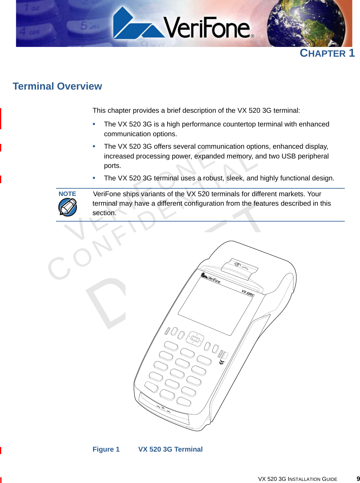
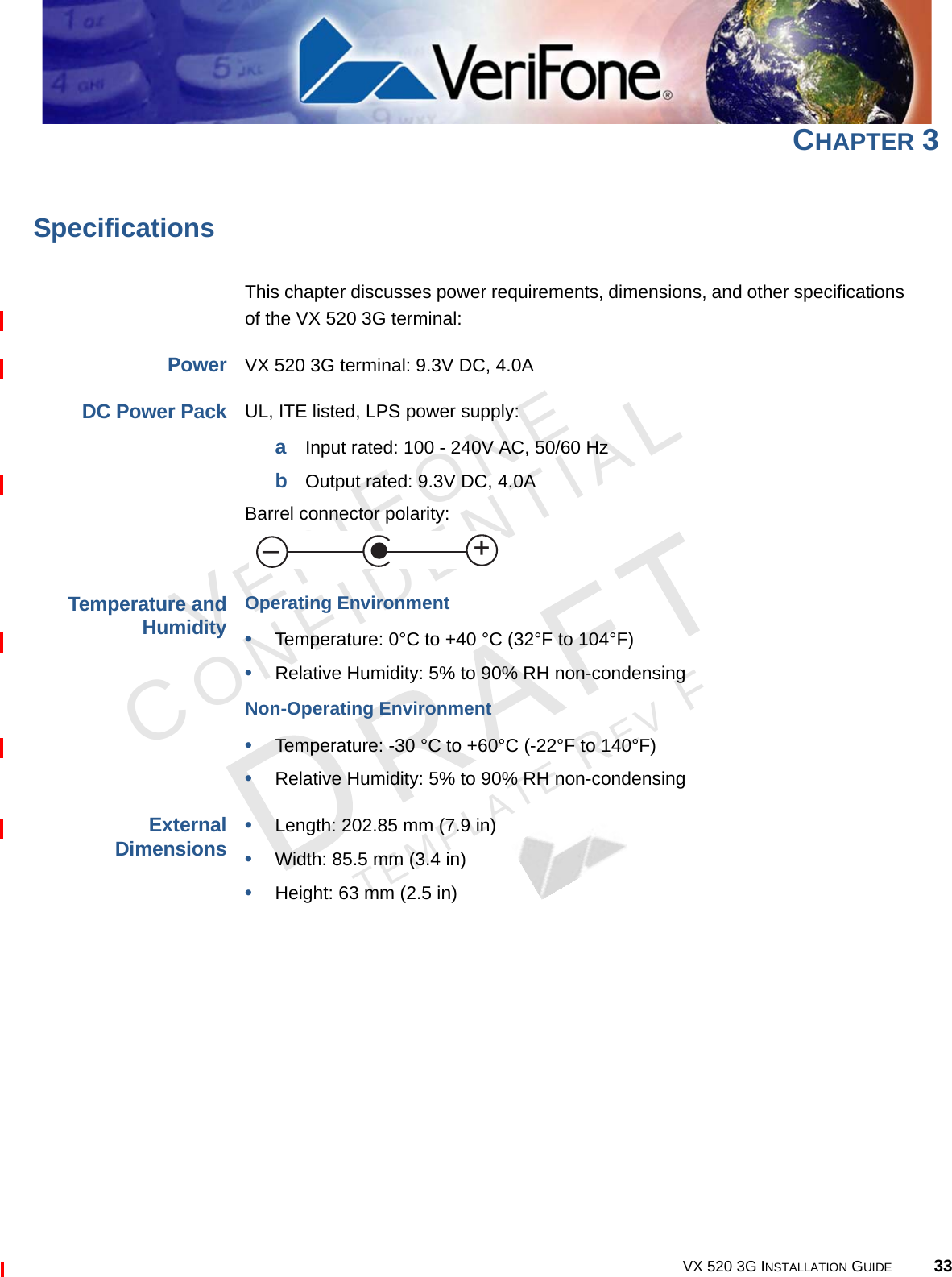
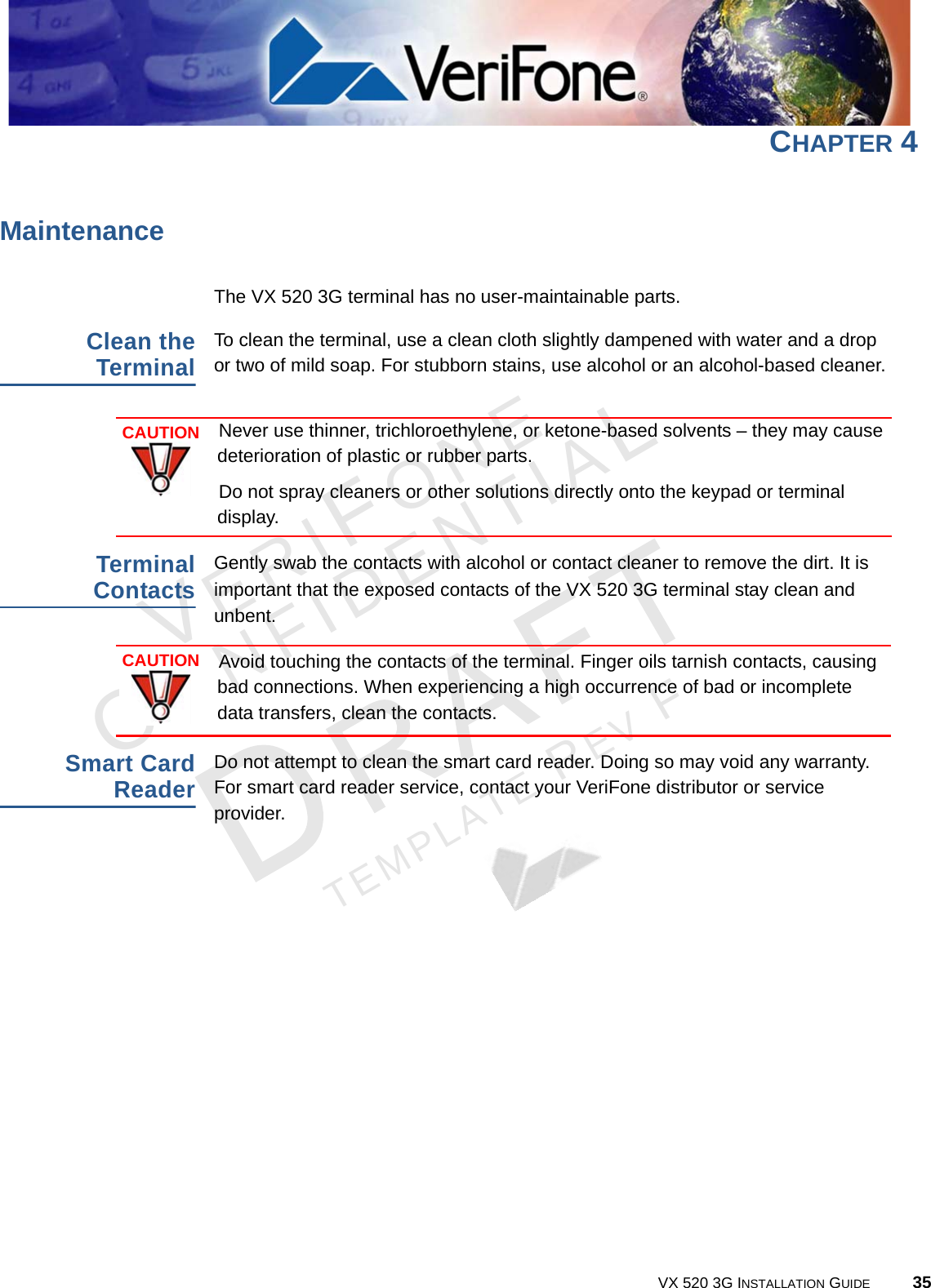
VeriFone Inc POINT OF SALE TERMINAL VX 520 3G Installation Guide
UserManual.wiki
>
Verifone
>
VX520WCDMA User Manual
>
User Manual
Contents
1.
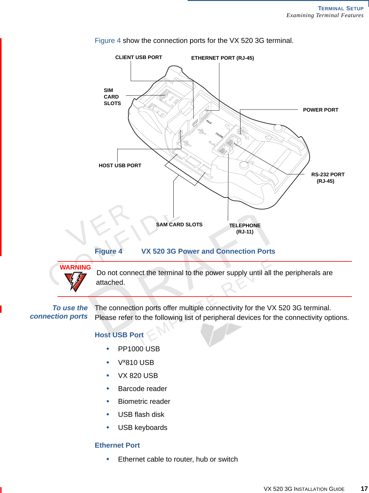
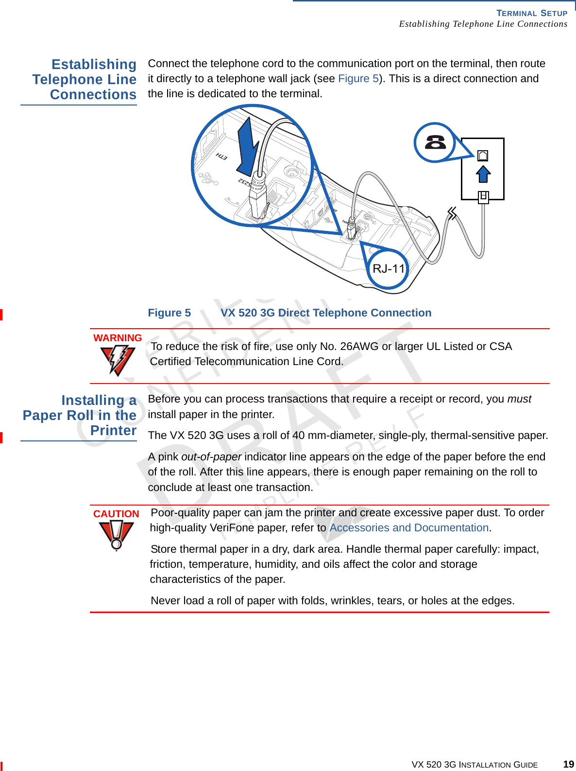
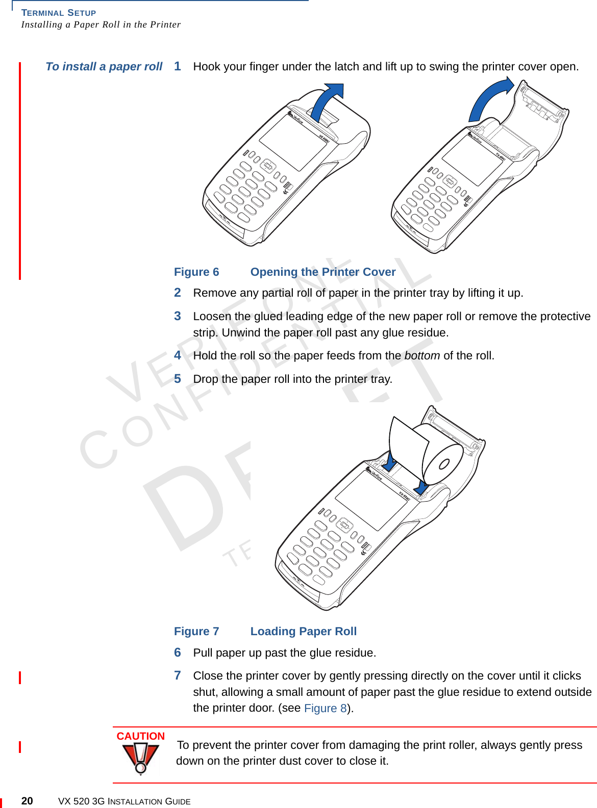
User Manual
2.
User Manual Regulatory
User Manual
Navigation menu
Upload a User Manual
Namespaces
Wiki Guide
HTML
PDF
Info
Views
User Manual
Discussion / Help
Navigation