Verifone VX680BTWIFI Point of Sale Terminal User Manual VX 680 Installation Guide
VeriFone Inc Point of Sale Terminal VX 680 Installation Guide
Verifone >
Contents
- 1. user manual 1 of 2
- 2. user manual 2 of 2
- 3. User Manual 1 of 2
- 4. User Manual 2 of 2
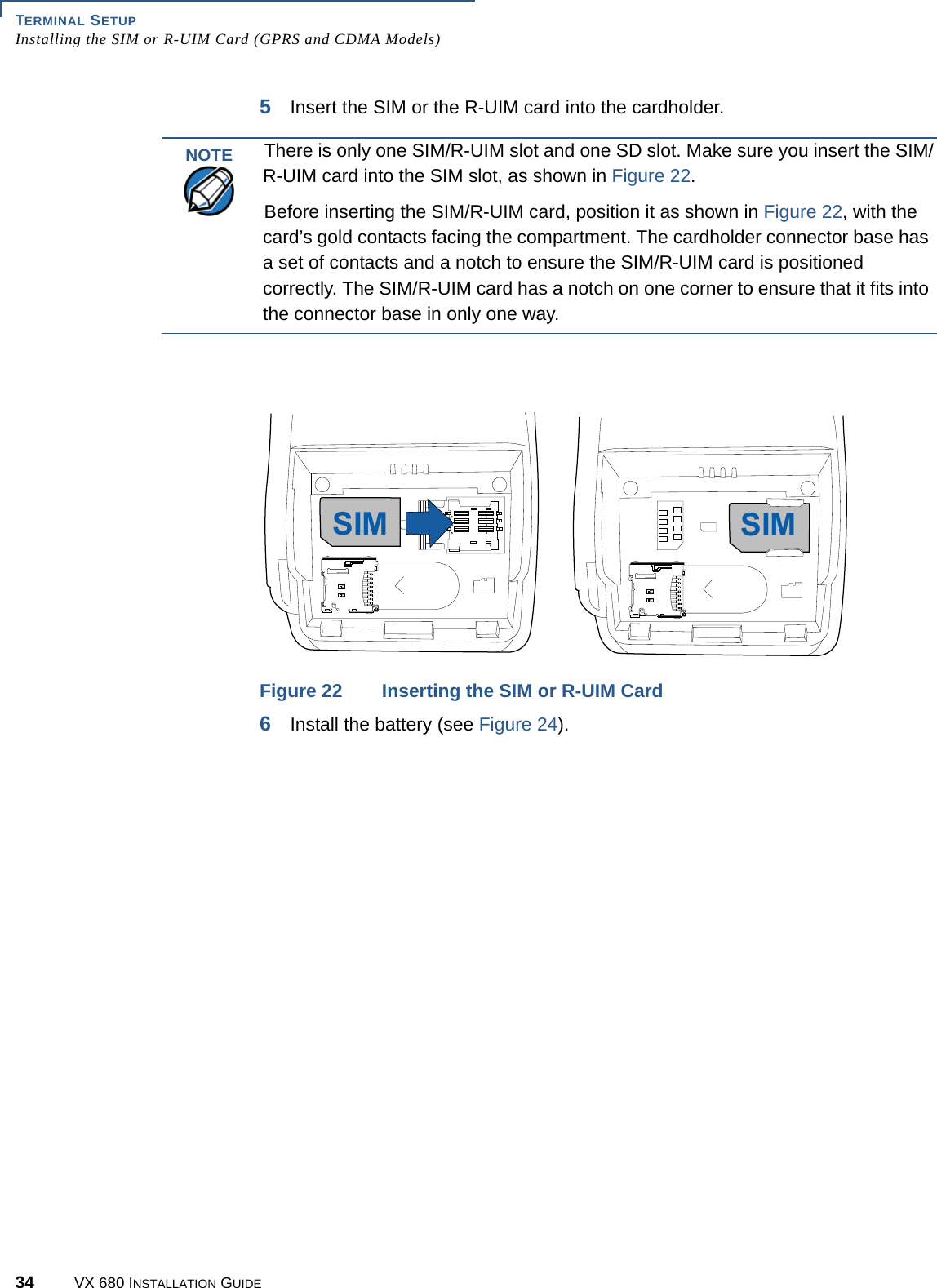
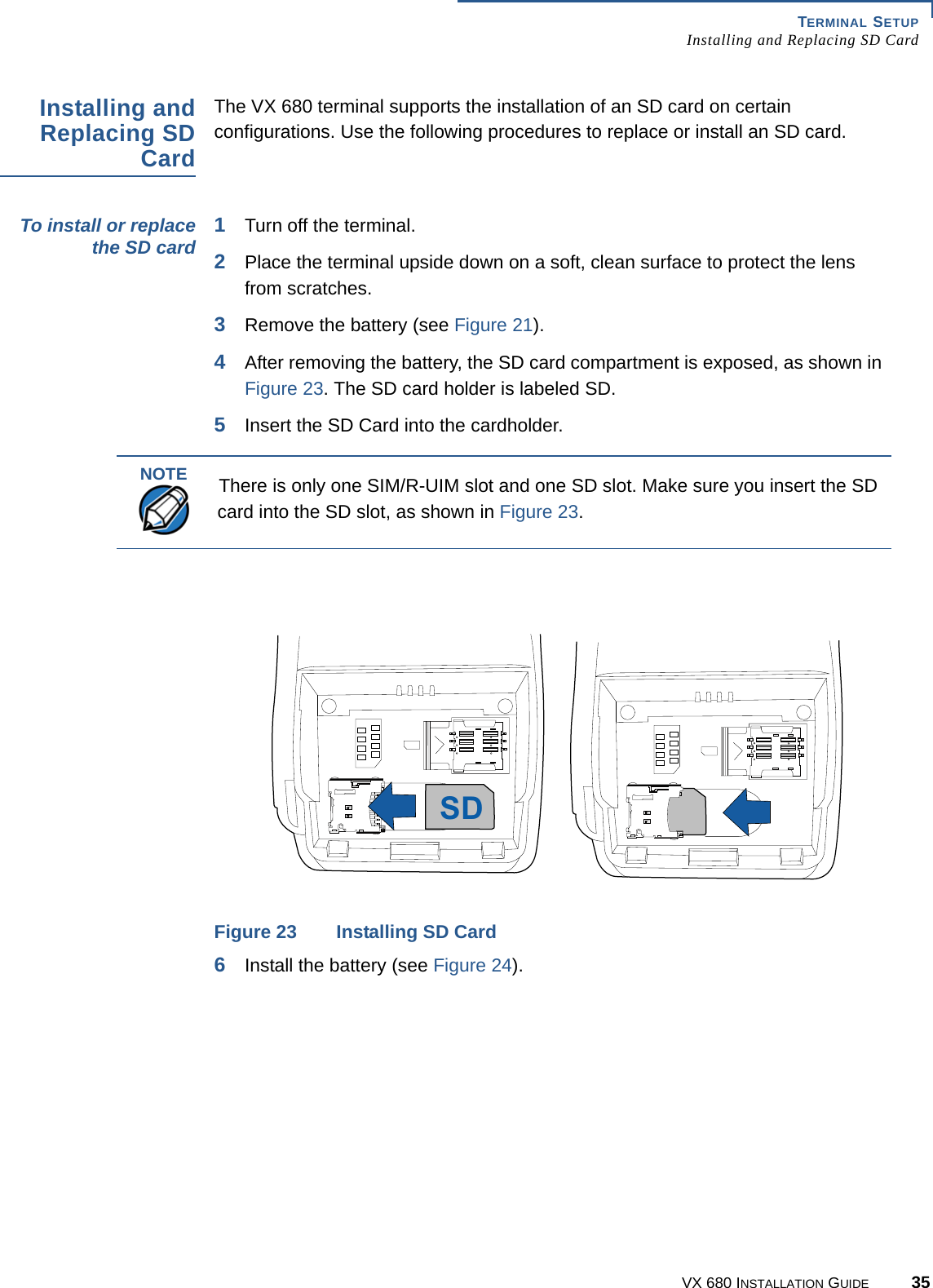
user manual 1 of 2