Vertex Standard USA 11464620 Handheld Portable UHF Non-Display fixed antenna User Manual EVX S24 OM ENG EC146U100 FCC 160817 indd
Vertex Standard USA, Inc. Handheld Portable UHF Non-Display fixed antenna EVX S24 OM ENG EC146U100 FCC 160817 indd
Contents
- 1. Users Manual
- 2. User Manual
Users Manual

IP67 Dust- and Waterproof
Compact Portable Digital Two Way Radio
with Analog Capability
EVX-S24
OPERATING MANUAL
Exhibit 8: Operating Manual
FCC ID: AXI11464620
IC: 10239A-11464620
Vertex Standard LMR, Inc.

Introduction .....................................................................1
Class B Digital Device .....................................................2
Warning! FCC RF Exposure Requirements .................3
Warning! IC RSS General Requirement ......................5
Controls & Connectors ...................................................7
LCD Icon & Indicators ...................................................8
Before You Begin .............................................................9
Battery Pack Installation .............................................9
Battery Pack Removal .................................................9
Belt Clip Installation .................................................10
Antenna Installation ..................................................10
Battery Charging ....................................................... 11
Low Battery Indication ..............................................12
Operation ....................................................................... 13
Preliminary Steps ......................................................13
Operation Quick Start ................................................13
Automatic Time-Out Timer ....................................... 15
ARTS™ (Auto Range Transpond System) ...............16
LOCK ........................................................................16
Advanced Operation .....................................................17
Programmable Key Functions ..................................17
Description of Operating Functions .........................19
User Set (Menu) Mode ..................................................31
Optional Accessories .....................................................39
Warranty Policy ............................................................40
CONTENTS
Congratulations!
You now have at your fi ngertips a valuable communications tool, a Vertex Standard two-way radio! Rugged, reliable and
easy to use, your Vertex Standard radio will keep you in constant touch with your colleagues for years to come, with negli-
gible maintenance down-time. Please take a few minutes to read this manual carefully. The information presented here will
allow you to derive maximum performance from your radio, in case questions arise later on.
Important Note
There are no owner-serviceable parts inside the radio. All service jobs must be referred to an authorized Vertex
Standard Service Representative.
In order to maintain the specifi ed water integrity performance, periodic maintenance is recommended.
Should the radio sustain a severe shock (e.g. if it is dropped), the water integrity may be compromised, requiring
service. Should this occur, contact your Authorized Vertex Standard Dealer.
Exhibit 8: Operating Manual
FCC ID: AXI11464620
IC: 10239A-11464620
Vertex Standard LMR, Inc.

EVX-S24 OPERATING MANUAL 1
Important Notice for North American Users Regarding 406 MHz Guard Band
The U.S. Coast Guard and National Oceanographic and Atmospheric Administration have requested the cooperation
of the U.S. Federal Communications Commission in preserving the integrity of the protected frequency range 406.0
to 406.1 MHz, which is reserved for use by distress beacons. Do not attempt to program this apparatus, under any
circumstances, for operation in the frequency range 406.0 - 406.1 MHz if the apparatus is to be used in or near North
America.
Warning - Frequency band 406 - 406.1 MHz is reserved for use ONLY as a distress beacon by the US Coast Guard
and NOAA. Under no circumstance should this frequency band be part of the pre programmed operating frequencies
of this radio.
INTRODUCTION
The EVX-S24 is full-featured, compact Portable Digital/Analog Transceiver designed for business communications in the
UHF Land Mobile band. The EVX-S24 supports up to 256 user confi gurable channels within a maximum 16 groups, sup-
porting a wide variety of business applications.
Channel frequency data for the transceiver is stored in fl ash memory, which is easily programmed by Vertex Standard li-
censed dealers using a standard PC and the following Vertex Standard programming equipment:
CE157 PC Programming Software
CB000262A01 Micro USB Programming Cable
This manual will describe in detail the many advanced features of the EVX-S24. After reading this manual, you may wish
to consult with your Network Administrator regarding precise details of the confi guration of this equipment for use in your
application.
Exhibit 8: Operating Manual
FCC ID: AXI11464620
IC: 10239A-11464620
Vertex Standard LMR, Inc.

2 EVX-S24 OPERATING MANUAL
CLASS B DIGITAL DEVICE
NOTE: This equipment has been tested and found to comply with the limits for a Class B digital device, pursuant to part 15
of the FCC Rules. These limits are designed to provide reasonable protection against harmful interference in a residential
installation. This equipment generates uses and can radiate radio frequency energy and, if not installed and used in accor-
dance with the instructions, may cause harmful interference to radio communications. However, there is no guarantee that
interference will not occur in a particular installation. If this equipment does cause harmful interference to radio or televi-
sion reception, which can be determined by turning the equipment off and on, the user is encouraged to try to correct the
interference by one or more of the following measures:
Reorient or relocate the receiving antenna.
Increase the separation between the equipment and receiver.
Connect the equipment into an outlet on a circuit different from that to which the receiver is connected.
Consult the dealer or an experienced radio/TV technician for help.
Exhibit 8: Operating Manual
FCC ID: AXI11464620
IC: 10239A-11464620
Vertex Standard LMR, Inc.
EVX-S24 OPERATING MANUAL 3
WARNING! FCC RF EXPOSURE REQUIREMENTS
THIS DEVICE COMPLIES WITH PART 15 OF THE FCC RULES. OPERATION IS SUBJECT TO THE FOLLOWING TWO CON-
DITIONS: (1) THIS DEVICE MAY NOT CAUSE HARMFUL INTERFERENCE, AND (2) THIS DEVICE MUST ACCEPT ANY IN-
TERFERENCE RECEIVED, INCLUDING INTERFERENCE THAT MAY CAUSE UNDESIRED OPERATION.
This Radio has been tested and complies with the Federal Communications Commission (FCC) RF exposure limits for Oc-
cupational Use/Controlled exposure environment. In addition, it complies with the following Standards and Guidelines:
FCC 96-326, Guidelines for Evaluating the Environmental Effects of Radio-Frequency Radiation.
FCC OET Bulletin 65 Edition 97-01 (2001) Supplement C, Evaluating Compliance with FCC Guidelines for Human
Exposure to Radio Frequency Electromagnetic Fields.
ANSI/IEEE C95.1-1992, IEEE Standard for Safety Levels with Respect to Human Exposure to Radio Frequency Elec-
tromagnetic Fields, 3 kHz to 300 GHz.
ANSI/IEEE C95.3-1992, IEEE Recommended Practice for the Measurement of Potentially Hazardous Electromagnetic
Fields - RF and Microwave.
WARNING:
This radio generates RF electromagnetic energy during transmit mode. This radio is designed for and classifi ed as
Occupational Use Only, meaning it must be used only during the course of employment by individuals aware of the
hazards, and the ways to minimize such hazards. This radio is not intended for use by the General Population in an
uncontrolled environment.
CAUTION:
To ensure that your expose to RF electromagnetic energy is within the FCC allowable limits for occupational use,
always adhere to the following guidelines:
This radio is NOT approved for use by the general population in an uncontrolled exposure environment. This ra-
dio is restricted to occupational use, work related operations only where the radio operator must have the knowl-
edge to control his or her RF exposure conditions.
Exhibit 8: Operating Manual
FCC ID: AXI11464620
IC: 10239A-11464620
Vertex Standard LMR, Inc.

4 EVX-S24 OPERATING MANUAL
WARNING! FCC RF EXPOSURE REQUIREMENTS
When transmitting, hold the radio in a vertical position with its microphone 1 inch (2.5 cm) away from your
mouth and keep the antenna at least 1 inch (2.5 cm) away from your head.
Transmit no more than the rated duty factor of 50% of the time. To transmit (talk), push the Push-To-Talk (PTT)
button. To receive calls, release the PTT button. The PTT button may reside on the radio itself or may be hosted
on approved accessories. Transmitting 50% of the time, or less, is important because this radio generates mea-
surable RF energy exposure only when transmitting (in terms of measuring for standards compliance).
The radio is transmitting when the red (analog mode) or blue (digital mode) LED on the top of the radio is illu-
minated. You can cause the radio to transmit by pressing the P-T-T button.
In front of the face. Hold the radio in a vertical position with the microphone (and other parts of the radio in-
cluding the antenna) at least 1 inch (2.5 cm) away from the nose or lips. Keeping the radio at a proper distance is
important to ensure compliance.
Body Worn Operation: When worn on the body, always place the radio in a Vertex Standard approved clip, hold-
er, holster, case, or body harness for this product. Using approved body-worn accessories is important because
the use of non-Vertex Standard approved accessories may result in exposure levels, which exceed the occupation-
al/controlled environment RF exposure limits.
Always use Vertex Standard authorized accessories.
The information listed above provides the user with the information needed to make him or her aware of RF ex-
posure, and what to do to assure that this radio operates with the FCC RF exposure limits of this radio.
Electromagnetic Interference/Compatibility
During transmissions, this radio generates RF energy that can possibly cause interference with other devices or
systems. To avoid such interference, turn off the radio in areas where signs are posted to do so.
Do not operate the transmitter in areas that are sensitive to electromagnetic radiation such as hospitals, health
care facilities, aircraft, and blasting sites.
Exhibit 8: Operating Manual
FCC ID: AXI11464620
IC: 10239A-11464620
Vertex Standard LMR, Inc.
EVX-S24 OPERATING MANUAL 5
WARNING! IC RSS GENERAL REQUIREMENT
ENGLISH
This device complies with Industry Canada’s license-exempt RSSs. Operation. Operation is subject to the following two
conditions:
(1) This device may not cause interference; and
(2) This device must accept any interference, including interference that may cause undesired operation of the device.
Under Industry Canada regulations, this radio transmitter may only operate using an antenna of a type and maximum (or
lesser) gain approved for the transmitter by Industry Canada. To reduce potential radio interference to other users, the
antenna type and its gain should be so chosen that the equivalent isotropically radiated power (e.i.r.p.) is not more than
that necessary for successful communication.
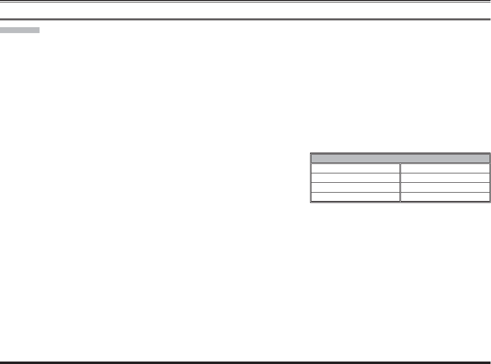
This radio transmitter (identify the device by certifi cation number, or model number if Category II) has been approved
by Industry Canada to operate with the antenna types listed at the right
with the maximum permissible gain and required antenna impedance
for each antenna type indicated. Antenna types not included in this list,
having a gain greater than the maximum gain indicated for that type, are
strictly prohibited for use with this device.
When transmitting, hold the radio in a vertical position with its microphone 1 inch (2.5 cm) away from your
mouth and keep the antenna at least 1 inch (2.5 cm) away from your head.
The radio must be used with a maximum operating duty cycle not exceeding 50%, in typical Push-to-Talk con-
fi gurations.
DO NOT transmit for more than 50% of total radio use time (50% duty cycle). Transmitting more than 50% of
the time can cause IC RSS General Requirement to be exceeded. The radio is transmitting when the red LED on
the top of the radio is illuminated.
Body Worn Operation: When worn on the body, always place the radio in a Vertex Standard approved clip, hold-
er, holster, case, or body harness for this product. Using approved body-worn accessories is important because
the use of non-Vertex Standard approved accessories may result in exposure levels, which exceed the occupation-
al/controlled environment RF exposure limits.
APPROVED ANTENNA
ATU-6A: −2.15 dBi, 50-ohm ATU-20AS: −2.15 dBi, 50-ohm
ATU-6B: −2.15 dBi, 50-ohm ATU-20DS: −2.15 dBi, 50-ohm
ATU-6C: −2.15 dBi, 50-ohm ATU-20FS: −2.15 dBi, 50-ohm
ATU-6D: −2.15 dBi, 50-ohm ---
Exhibit 8: Operating Manual
FCC ID: AXI11464620
IC: 10239A-11464620
Vertex Standard LMR, Inc.
6 EVX-S24 OPERATING MANUAL
FRENCH
Le présent appareil est conforme aux CNR d’Industrie Canada applicables aux appareils radio exempts de licence. L’ex-
ploitation est autorisée aux deux conditions suivantes :
(1) l’appareil ne doit pas produire de brouillage, et
(2) l’utilisateur de l’appareil doit accepter tout brouillage radioélectrique subi, même si le brouillage est susceptible d’en
compromettre le fonctionnement.
Conformément à la réglementation d’Industrie Canada, le présent émetteur radio peut fonctionner avec une antenne
d’un type et d’un gain maximal (ou inférieur) approuvé pour l’émetteur par Industrie Canada. Dans le but de réduire les
risques de brouillage radioélectrique à l’intention des autres utilisateurs, il faut choisir le type d’antenne et son gain de
sorte que la puissance isotrope rayonnée quivalente (p.i.r.e.) ne dépassepas l’intensité nécessaire à l’établissement d’une
communication satisfaisante.
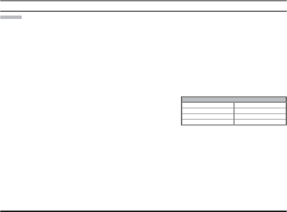
Le présent émetteur radio (identifi er le dispositif par son numéro de certifi cation ou son numéro de modèle s’il fait par-
tie du matériel de catégorie I) a été approuvé par Industrie Canada pour
fonctionner avec les types d’antenne énumérés dans le droit et ayant un
gain admissible maximal et l’impédance requise pour chaque type d’an-
tenne. Les types d’antenne non inclus dans cette liste, ou dont le gain est
supérieur au gain maximal indiqué, sont strictement interdits pour l’ex-
ploitation de l’émetteur.
Pour émettre, tenez votre radio verticalement en plaçant le microphone entre 2,5 cm de la bouche. L’antenne doit
toujours être à plus de 2,5 cm de votre tête.
Le temps total d’émission de la radio ne doit pas dépasser 50% du temps de fonctionnement dans une confi guration
normale avec alternat.
Par conséquent, vous ne devez PAS émettre pendant plus de 50% du temps total d’utilisation de la radio. La radio
émet lorsque le voyant LED rouge (situé au sommet de la radio) est allumé.
Utilisation lorsque la radio est portée sur soi: Lorsque la radio est portée sur soi, utilisez toujours une pince ou
une attache de ceinture, placez-la dans un étui ou dans un harnais pour le corps approuvé par Vertex Standard
pour ce produit. Il est important d’utiliser des accessoires ajustés au corps qui sont approuvés, car dans le cas
contraire, l’utilisateur risque de s’exposer à des niveaux d’énergie de RF supérieurs aux limites établies pour les
environnements professionnels ou à exposition contrôlée.
WARNING! IC RSS GENERAL REQUIREMENT
ANTENNE APPROUVÉ
ATU-6A: −2.15 dBi, 50-ohm ATU-20AS: −2.15 dBi, 50-ohm
ATU-6B: −2.15 dBi, 50-ohm ATU-20DS: −2.15 dBi, 50-ohm
ATU-6C: −2.15 dBi, 50-ohm ATU-20FS: −2.15 dBi, 50-ohm
ATU-6D: −2.15 dBi, 50-ohm ---
Exhibit 8: Operating Manual
FCC ID: AXI11464620
IC: 10239A-11464620
Vertex Standard LMR, Inc.
EVX-S24 OPERATING MANUAL 7
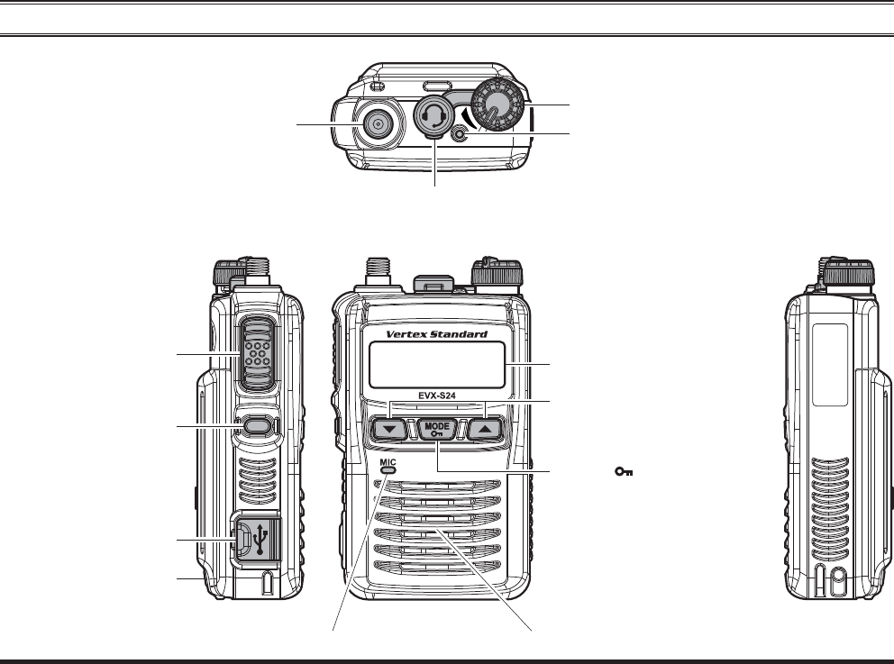
MIC/SP Jack
(External MIC/SP)
CONTROLS & CONNECTORS
LED Indicator (
Programmable
)
Default settings are:
Steady Blue: Transmitting in Progress (Digital)
Steady Red: Transmitting in Progress (Analog)
Blinking Green: Busy Channel
Steady Green: Channel Monitor
Blinking Yellow: Emergency function is active
Blinking Red: Low Battery Power
PTT Switch
SIDE Key (
Programmable
)
Default settings are:
Press Key: LAMP “On”
Press and Hold Key: Non Assignment
Micro USB Jack
SpeakerMicrophone
Antenna Jack
VOL (Volume)/PWR (Power) Knob
LCD (Liquid Crystal Display)
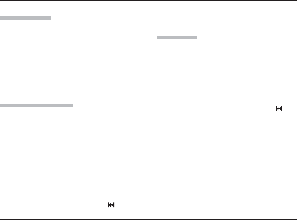
[]/[] Key (
Programmable
)
Default settings are:
Press Key: Channel Up/Down
Press & Hold Key: Speed Channel Up/Down
[MODE( )] Key (
Programmable
)
Default settings are:
Press Key: User Set Mode Active
Press & Hold Key: Key Lock Function
Battery Cover Latch
(Rear Side)
Exhibit 8: Operating Manual
FCC ID: AXI11464620
IC: 10239A-11464620
Vertex Standard LMR, Inc.
8 EVX-S24 OPERATING MANUAL
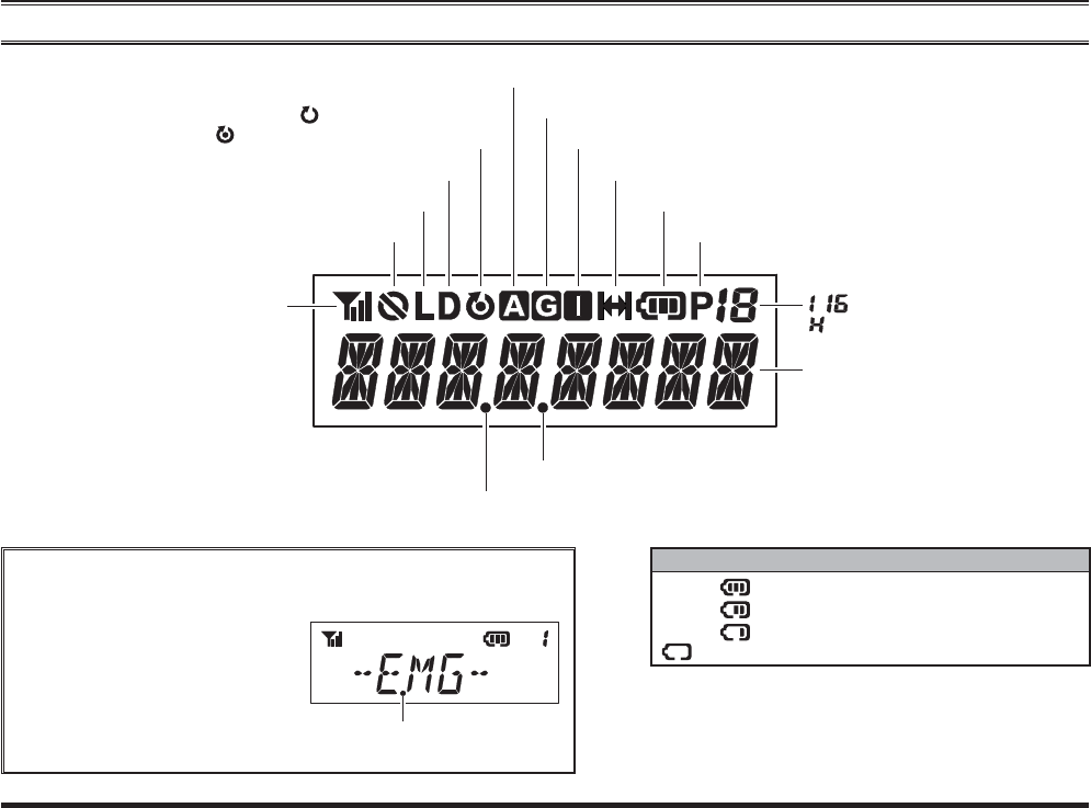
LCD ICON & INDICATORS
“Privacy” or “Encryption” is activated
Low Transmit Power Mode “On”
“Dual Watch” is activated
: “Scan” is enabled
: “Priority Scan” is Activated
TX ID Type is “All Call”
“Talk-Around” is enabled
Battery Gauge
Priority-2 Channel
8-character
Alpha-numeric Display
“Group Scan” is enabled
TX Power & RSSI Indicator
(Four Steps)
“Lone Worker” is activated
TX ID Type is “Group Call”
TX ID Type is “Individual Call (Private Call)”
BATTERY GAUGE
:
:
:
w/blink :
Full Battery Power
Moderate Battery Power
Low Battery Power
Poor Battery Power (Charge the Battery)
These small dot indication will appear continuously until deacti-
vated, regardless of the operation status of other active features.
For example, the LCD pictured
to the right shows an active
emergency feature, which con-
tinues to be visible even during
an emergency call, when acti-
vated on the radio.
“Lone Worker” is activated
~ : Group Number
: Priority-1 Channel
Exhibit 8: Operating Manual
FCC ID: AXI11464620
IC: 10239A-11464620
Vertex Standard LMR, Inc.
EVX-S24 OPERATING MANUAL 9
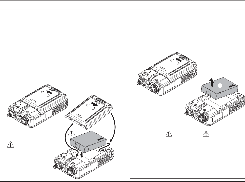
BEFORE YOU BEGIN
Battery Pack Removal
1. Turn the radio off and remove any protective cases.
2. Slide the Battery Cover Latch into the “UNLOCK”
side, then remove the Battery Cover.
3. Pinch the top side of the Battery Pack, then pull out
the Battery Pack.
Battery Pack Installation
1. Make sure that the VOL/PWR knob powered off, by
turning the knob counter clockwise to a complete stop.
2. Slide the Battery Cover Latch into the “UNLOCK”
position, then remove the Battery Cover.
3. Install the
FNB-V142LI Battery Pack into the battery
compartment of the transceiver.
4. Re-attach the battery cover by aligning the tabs of the
battery cover with the slots on the transceiver and slid-
ing into position.
5. Slide the Battery Cover Latch into the “LOCK” posi-
tion.
CAUTION
Risk of explosion if battery is replaced by an
incorrect type. Dispose of used batteries ac-
cording to the instructions.
Do not attempt to open any of the recharge-
able Lithium-Ion packs, as they could ex-
plode if accidentally short-circuited.
Use the Vertex Standard
FNB-V142LI Lithium-Ion
Battery Pack only.
Exhibit 8: Operating Manual
FCC ID: AXI11464620
IC: 10239A-11464620
Vertex Standard LMR, Inc.
10 EVX-S24 OPERATING MANUAL
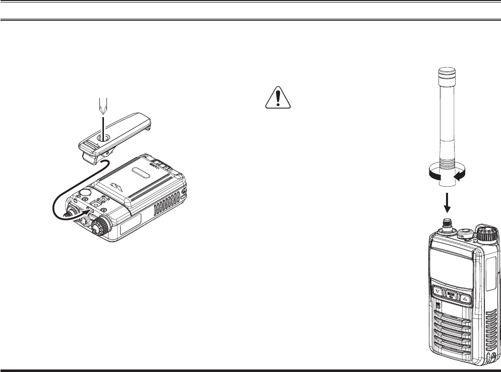
Belt Clip Installation
Align the tab in the upper side of the Belt Clip to the slot
on the transceiver, and then secure the Belt Clip by tight-
ening the belt clip screw to the radio chassis with a Phil-
lips head screwdriver.
BEFORE YOU BEGIN
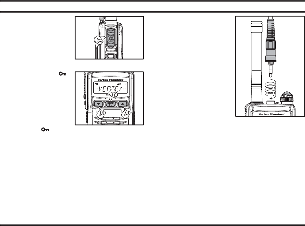
Antenna Installation
Hold the bottom end of the antenna, then screw it onto the
mating connector on the transceiver until snug. Do not
over-tighten with extreme force.
Never transmit without hav-
ing an antenna connected.
Exhibit 8: Operating Manual
FCC ID: AXI11464620
IC: 10239A-11464620
Vertex Standard LMR, Inc.
EVX-S24 OPERATING MANUAL 11
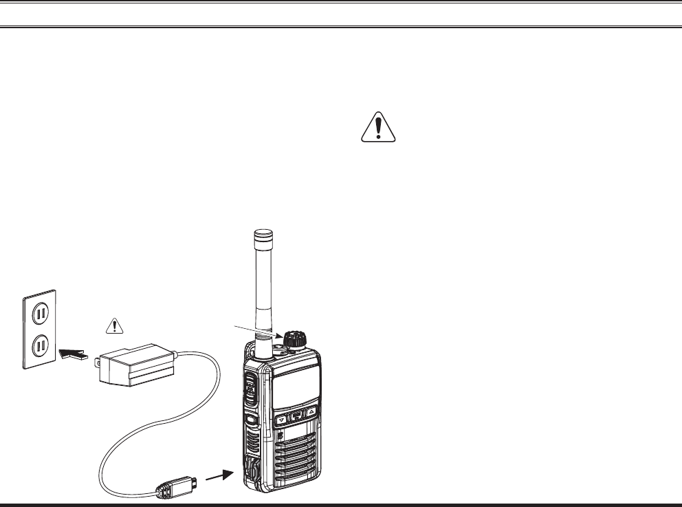
BEFORE YOU BEGIN
Battery Charging
Turn the transceiver off.
Open the Rubber Cover of the USB Jack.
Insert the Micro USB plug from the optional PA-57
AC Adapter into the Micro USB jack on the transceiv-
er, and then connect the PA-57 AC Adapter to the AC
line outlet.
If the battery pack is installed correctly, the LED in-
dicator on the top of the transceiver will glow red and
the charging starts. A fully-discharged battery pack
will charge completely in 1.5 - 4.5 hours.
When charging is completed, the LED
indicator will turn off.
Disconnect the Micro USB plug from the transceiver
and close the Rubber Cover of the USB Jack.
Unplug the
PA-57 AC Adapter from the AC line out-
let.
1) Turn the transceiver off, when charging the
battery.
2) Always use the Vertex Standard FNB-V142LI Lithi-
um-Ion Battery Pack.
3) Batteries carry a risk of explosion if replaced by an
incorrect type.
4) Use only the Vertex Standard PA-57 AC Adapter, or
Vertex Standard approved Charger.
5) Do not connect the USB charger other than PA-57 AC
Adapter, as cause to damage the battery and transceiver.
6) Vertex Standard prohibits the battery charge with a
combination of the common Micro USB cable and USB
power supply.
7) To reduce the risk of explosion, recharge the batteries
outside of hazardous locations.
8) Perform the battery charging where the ambient tem-
perature range +41 °F to +104 °F (+5 °C to +40 °C).
Charging outside of this temperature range could cause
damage to the battery pack.
9) The Battery Pack should not be exposed to excessive
heat such as sunshine, fi re, or similar heat sources.
10) This transceiver does not keep the Dust- and Water-
Micro USB jack
AC Line Out
PA-57 AC Adapter
Turn the transceiver off
Exhibit 8: Operating Manual
FCC ID: AXI11464620
IC: 10239A-11464620
Vertex Standard LMR, Inc.

12 EVX-S24 OPERATING MANUAL
BEFORE YOU BEGIN
proof rating (IP67) when the Rubber Cover is not se-
cured over the USB jack. Low Battery Indication
As the battery discharges during use, the voltage gradually
becomes lower. When the battery voltage becomes too
low, substitute a freshly charged battery and recharge the
depleted pack. The LED indicator on the top of the radio
will blink red when the battery voltage is low.
You may confirm the battery condition by the Battery
Gauge on the display. See page 8 for more information.
Exhibit 8: Operating Manual
FCC ID: AXI11464620
IC: 10239A-11464620
Vertex Standard LMR, Inc.
EVX-S24 OPERATING MANUAL 13
OPERATION
Preliminary Steps
Install a battery pack into the transceiver and charge
the battery fully, as described previously.
Screw the supplied antenna onto the Antenna jack, as
described previously.
It is not recommended to operate this transceiver with-
out an antenna connected.
If you have a Speaker/Microphone, we recommend
that it not be connected until you are familiar with the
basic operation of the EVX-S24. Refer to next page
for more information about Speaker/Microphone us-
age.
IMPORTANT NOTE
The dust- and waterproof rating of the transceiver
(IP67) is assured only when the following condi-
tions are met:
Battery Cover is attached to the transceiver;
Antenna is connected to the antenna jack;
Rubber Cover is installed over the Micro USB
jack.
MIC/SP cap is installed in the MIC/SP jack.
Or the Speaker/Microphone that approved with
an IP67 rating by Vertex Standard is installed in
the MIC/SP jack.
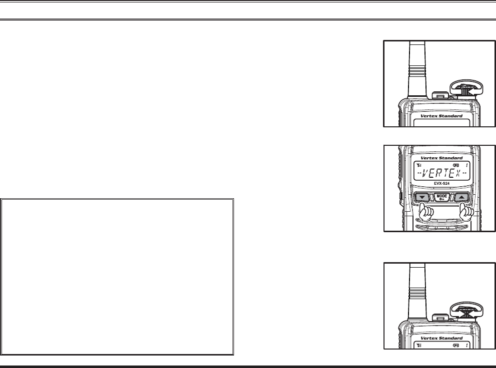
Operation Quick Start
Turn the top panel’s
VOL/PWR knob clock-
wise to turn on the radio.
Press the
[]/[] key to choose the desired operating
channel.
If you want to select the
operating channel from a
different Channel Group,
press (or press and hold)
the Programmable key
(assigned to the “Group
Up/Down” function) to change desired Channel Group
before selecting the operating channel.
Rotate the VOL/PWR
knob to set the volume
level.
Exhibit 8: Operating Manual
FCC ID: AXI11464620
IC: 10239A-11464620
Vertex Standard LMR, Inc.
14 EVX-S24 OPERATING MANUAL
OPERATION
To transmit, press and
hold in the PTT switch.
Speak into the micro-
phone area of the front
panel grille in a normal
voice level.
To return to the receive mode, release the PTT switch.
Press the [MODE()]
key to enter the User Set
(Menu) Mode for acti-
vating the various func-
tions: press the []/[]
key to select the desired
function, and then press
the [MODE( )] key to initiate it.
See page 31 for more information regarding the “User
Set (Menu)” mode.
To install a speaker mi-
crophone or other audio
accessory, lift the rubber
cap from the MIC/SP
jack of the transceiver.
Make sure that the
transceiver is turned off,
then insert the threaded
microphone plug into
the MIC/SP jack, and
screw it into place until
tight, being careful not
to damage the Speaker/
Microphone cable. Inserting the plug into the jack will
disable the internal speaker. Hold the speaker grille up
next to your ear while receiving. To transmit, press the
PTT switch on the Speaker/Microphone, just as you
would on the main transceiver’s body, and speak into
the microphone on a normal voice level.
Note 1) When you press the PTT switch on the
Speaker/Microphone, it disables the internal micro-
phone, and vice versa.
2) To keep the Dust- and Waterproof (IP67), the rub-
ber cap should be reinstalled to the MIC/SP jack
when not using the Speaker/Microphone.
Exhibit 8: Operating Manual
FCC ID: AXI11464620
IC: 10239A-11464620
Vertex Standard LMR, Inc.
EVX-S24 OPERATING MANUAL 15
OPERATION
The EVX-S24 has two modes of DMR operation to
maximize spectrum efficiency. Standard operation
requires use of a TDMA repeater (such as the EVX-
R70) to utilize the repeater’s dual time slot capability
for doubling your radio fleet’s communication paths
for up to two simultaneous transmissions. The second
mode is Direct mode, which enables two communica-
tions paths on a single frequency, doubling your ca-
pacity with only the subscriber radios. No repeater is
necessary when operating in Direct mode.
If the BCLO (Busy Channel Lockout) feature has been
programmed on the channel, the radio will not transmit
when a carrier is present. Instead, the radio will gener-
ate short beep three times. Release the PTT switch and
wait for the channel to be clear of activity.
If the BTLO (Busy Tone Lockout) feature has been
programmed on an analog channel or CCLO (Color
Code Lockout) feature has been programmed on a dig-
ital channel, the radio can transmit only when there
is no carrier being received or when the carrier being
received includes the correct tone (CTCSS tone or
DCS code) on an analog channel or correct code on a
digital channel.
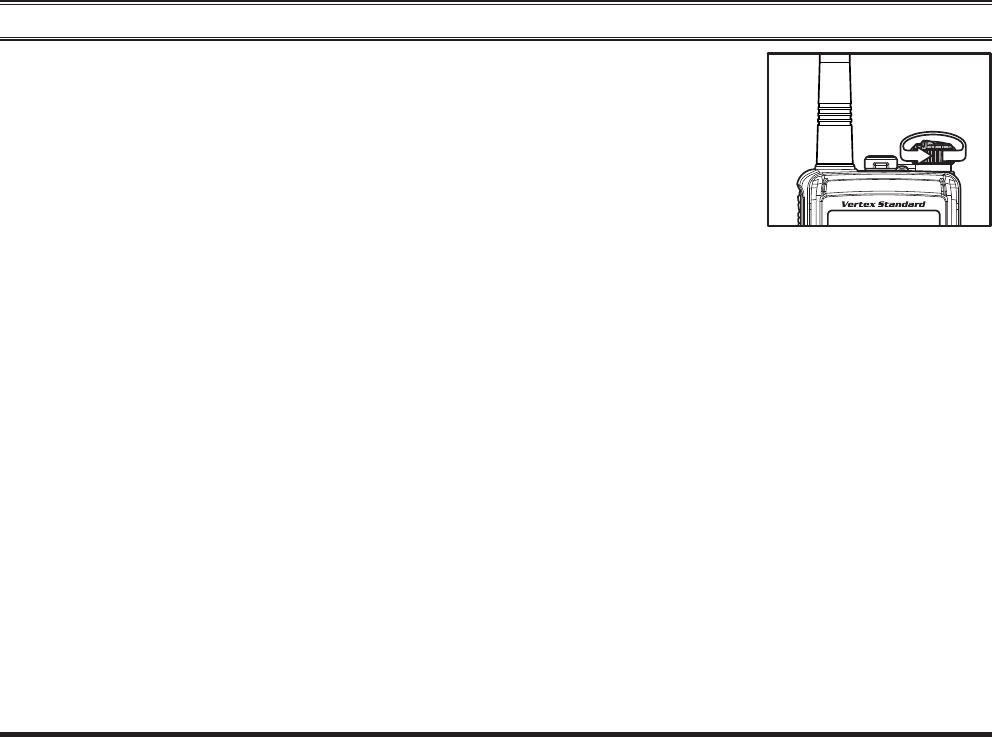
Turn the VOL/PWR
knob fully counter
clockwise to turn off the
radio.
Automatic Time-Out Timer
If the selected channel has been programmed with an Au-
tomatic Time-Out Timer, any transmission is limited to a
fi xed transmit time, dictated when programming the radio
with CE157 software. A ten second warning tone/beep
will sound before Automatic Time Out Timer is expired,
with a second tone/beep sounding when the radio offi-
cially reaches the pre-set maximum transmission time. In
addition, the top panel red LED (“TX” indicator) light will
turn off and any transmission activity will stop. To re-
sume transmission, the user must release the PTT switch
and await expiration of the “penalty timer”.
Exhibit 8: Operating Manual
FCC ID: AXI11464620
IC: 10239A-11464620
Vertex Standard LMR, Inc.
16 EVX-S24 OPERATING MANUAL
ARTS™
(Auto Range Transpond System)
This system is designed to inform the operator when you
and another ARTS™-equipped transceivers and stations
are within communication range using the DCS Encoder/
Decoder.
During ARTS™ operation, when the radio receives an
incoming ARTS™ signal, a short single beep will sound
and “IN SERV” (“In Service”) will be indicated on the
display for 2 seconds. If you move out of range for more
than two minutes, your radio senses that no signal has
been received, causing a short triple beep to sound and
“OUT SERV” (“Out of Service”) will be indicated on the
display for 2 seconds. Moving back into communications
range as the ARTS™ signal transmission from another
transceiver or station is back in range, a short single beep
will again sound and “IN SERV” (“In Service”) will be
indicated on the display for 2 seconds.
OPERATION
LOCK
In order to prevent accidental channel changes or inadver-
tent transmissions, various aspects of the Programmable
keys and PTT switch may be locked.
To activate the locking feature, press and hold the
[MODE()] key.
To cancel the key locking, press and hold the [MODE()]
key again.
You may change the lockout confi guration by the “User
Set (Menu)” mode. See page 36 for more information.
Exhibit 8: Operating Manual
FCC ID: AXI11464620
IC: 10239A-11464620
Vertex Standard LMR, Inc.
EVX-S24 OPERATING MANUAL 17
ADVANCED OPERATION
Programmable Key Functions
The EVX-S24 provides four Programmable Function (PF)
keys: [], [MODE( )], [] and [SIDE] keys.
These PF keys can be customized, via programming by
your Vertex Standard dealer, to meet your communica-
tions/network requirements.
The possible PF key programming features are illustrated
on the next page, and their functions are explained from
page 18. All functions can be assigned to any PF Key. Up
to two functions can be assigned per key, with the feature
being activated by:
Short Press (SP) - Press and release
Long Press (LP) - Press and hold
If further details are required, contact your Vertex Stan-
dard dealer.
In this chapter, the following icons are used to indicate
features supported in either the “Analog” mode or “Digital”
mode:
: Indicates an “Analog” mode only feature.
: Indicates a “Digital” mode only feature.
For features that are available in both “Analog” and “Dig-
ital” modes, no icon is shown.
For future reference, the table on the right side of the page
can be used to track each function assigned to the Pro-
grammable Function Keys on your radio.
Exhibit 8: Operating Manual
FCC ID: AXI11464620
IC: 10239A-11464620
Vertex Standard LMR, Inc.
18 EVX-S24 OPERATING MANUAL
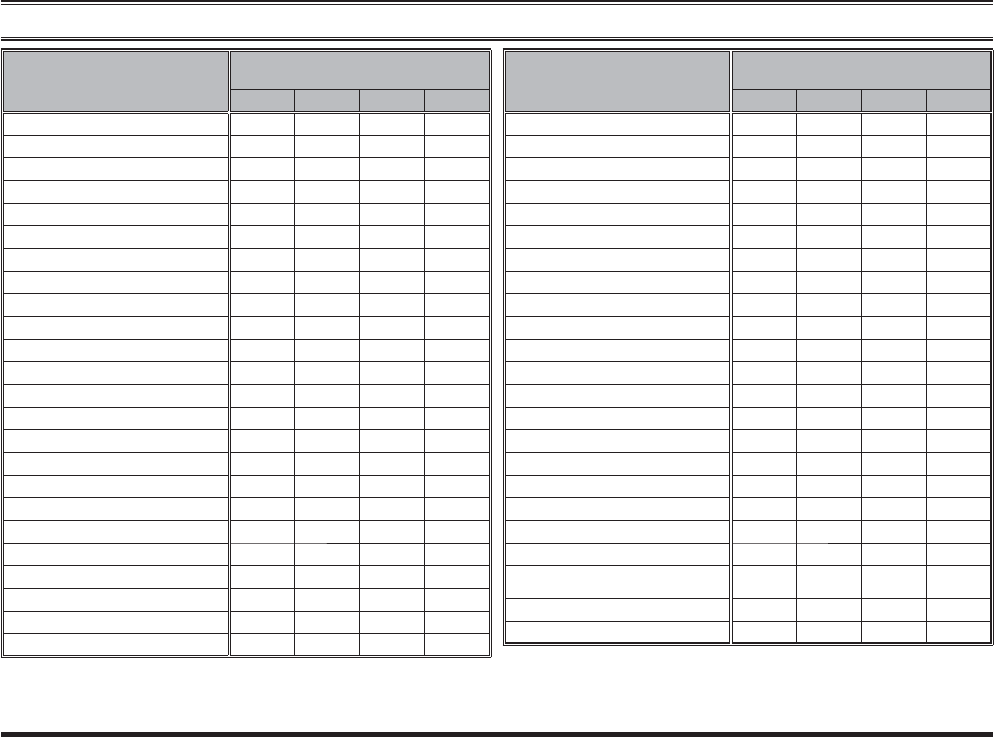
FUNCTION
PROGRAMMABLE KEY
(PRESS KEY / PRESS AND HOLD KEY)
[SIDE][
][
MODE][
]
None / / / /
Monitor / / / /
Lamp / / / /
Low Power / / / /
Privacy/Encryption / / / /
Privacy Set / / / /
SET ////
SQL OFF / / / /
SQL Set / / / /
Beep OFF / / / /
AF Min Volume / / / /
Whisper / / / /
Emergency1/ --- / --- / --- / ---
Lone Worker / / / /
Group Up / / / /
Group Down / / / /
CH Up / / / /
CH Down / / / /
Speed CH Up2--- / --- / --- / --- /
Speed CH Down2--- / --- / --- / --- /
PRI-1 / / / /
PRI-2 / / / /
PRI-2 Set / / / /
PRI-2 Disable / / / /
FUNCTION
PROGRAMMABLE KEY
(PRESS KEY / PRESS AND HOLD KEY)
[SIDE][
][
MODE][
]
Scan / / / /
Group Scan / / / /
Dual Watch / / / /
Follow Me Scan / / / /
Scan Set / / / /
Group Scan Set / / / /
TA Scan / / / /
Talk Around / / / /
Search / / / /
Reset / / / /
Code Up / / / /
Code Down / / / /
Speed Dial / / / /
Call / / / /
Status Up / / / /
Status Down / / / /
Status Check / / / /
Duty / / / /
ID Check / / / /
Text Message / / / /
TX Interrupt Remote Dekey
(REMOTE HALT TX)////
TX Save Disable / / / /
Lock / / / /
ADVANCED OPERATION
1: Emergency function can not assign to the LP function.
2: Speed CH Up/Down functions can not assign to the SP function.
Exhibit 8: Operating Manual
FCC ID: AXI11464620
IC: 10239A-11464620
Vertex Standard LMR, Inc.
EVX-S24 OPERATING MANUAL 19
ADVANCED OPERATION
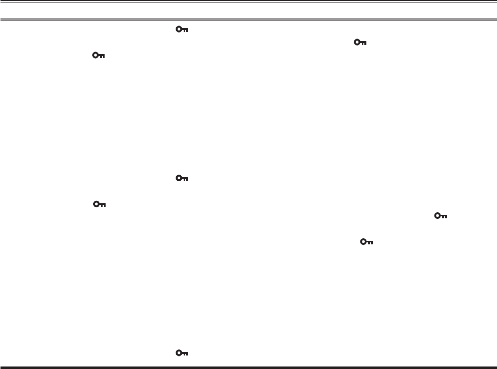
Description of Operating Functions ENCRYPTION
Analog Voice Inversion Encryption can be activated/deac-
tivated by an assigned PF key.
The “ ” icon will be indicated on the display when the
Encryption feature is activated.
PRIVACY SET
You can change the privacy settings to best meet your se-
curity requirements using this function:
Activates the “Privacy Set” function by an assigned
PF key. A tone will sound, and the “Tag” name corre-
sponding with the current Privacy Code will appear on
the display.
Press the []/[] keys to select the desired Privacy
Code. Up to 16 Privacy Codes are available for selec-
tion.
Press the
[MODE( )] key to store the new setting.
The display indicates “- SET -” briefl y, then reverts to
the normal channel indication.
You may cancel the new setting by press and holding
the [MODE()] key. In this case, the display indi-
cates “- CANCEL -” briefl y.
MONITOR
Any signaling features can be activated/deactivated by
an assigned PF key. The LED indicator will glow green
when the signaling feature is deactivated.
LAMP
Illuminates the back light of the display and keypad for
fi ve seconds.
LOW POWER
Toggle the radio’s transmit power “High” and “Low”. The
battery life will be extended in the “Low Power” mode.
The “L” icon will be indicated on the display when the
radio’s transmitter is set to “Low Power” mode.
PRIVACY
Digital Privacy feature can be activated/deactivated by an
assigned PF key. The Privacy feature initiates an encryp-
tion algorithm that will protect your communication from
unauthorized eavesdropping.
The “ ” icon will be indicated on the display when the
Privacy feature is activated.
Exhibit 8: Operating Manual
FCC ID: AXI11464620
IC: 10239A-11464620
Vertex Standard LMR, Inc.
20 EVX-S24 OPERATING MANUAL
ADVANCED OPERATION
SET
Activates the “User Set (Menu)” mode. See page 31 for
more information of the “User Set (Menu)” mode.
SQL OFF
SQL OFF opens the radio squelch/unmute the audio to hear
background noise.
SQL SET
You can manually adjust the squelch level using this func-
tion:
Activates the “SQL Set” function by an assigned PF
key. A tone will sound, and the current squelch level
will appear on the display.
Press the []/[] keys to select the desired squelch
level. Available selections are “SQLLV OP (Open)”,
“SQLLV TH (Threshold)”, “SQLLV NM (Normal)”
and “SQLLV TI (Tight)”.
Press the
[MODE( )] key to store the new setting.
The display indicates “- SET -” briefl y, then reverts to
the normal channel indication.
You may cancel the new setting by press and holding
the [MODE()] key. In this case, the display indi-
cates “- CANCEL -” briefl y.
BEEP OFF
Activation of Beep off disables all radio beeps (alert tones)
temporarily. Radio beeps will be restored by pressing the
PF key again.
When the Beep Off function is “on” and “off”, the display
indicates briefl y “BEEP OFF” and “BEEP ON”.
AF MIN VOLUME
Press the assigned PF key, the display indicates “AFATT
ON” briefl y, and reduce the audio output to the (lower)
level programmed. Again press the assigned PF key, the
display indicates “AFATT OF” briefl y, and resume nor-
mal audio output level.
You may change the programmed (lower) level by the
“User Set (Menu)” mode. See page 34 for more informa-
tion.
WHISPER
Whisper allows the user to increase the microphone gain,
allowing the operator to speak in a low voice (whisper)
temporarily when transmitting. The radio can go back to
normal microphone gain by pressing the assigned PF key
a second time.
When the Whisper function is “on” and “off”, the display
indicates briefl y “WHISP ON” and “WHISP OF”.
Exhibit 8: Operating Manual
FCC ID: AXI11464620
IC: 10239A-11464620
Vertex Standard LMR, Inc.

EVX-S24 OPERATING MANUAL 21
ADVANCED OPERATION
EMERGENCY
Emergency can either be programmed in analog or digital
mode. When the Emergency key is pressed, activate the
pre-programmed functions which is the LED indicator
will illuminate yellow and the EVX-S24 repeats the trans-
mission and reception 3 times for 10 seconds. This opera-
tions can be customized in the CE157 software by your
Vertex Standard authorized dealer.
To revive the radio from the Emergency mode, just press
again the assigned PF key or turn off the radio.
LONE WORKER
Toggle the Lone Worker feature “On” and “Off”.
The Lone Worker feature is designed to emit an alarm for
30 seconds when the Lone Worker Timer (programmed by
your Vertex Standard dealer) has expired. If the user does
not reset the timer by pressing the PTT switch, the radio
switches to Emergency mode.
When the Lone Worker feature is activated, a small dot
(“”) will be indicated at the bottom of the display. When
the Lone Worker feature is fi rst activated, the display indi-
cates “L-WK ON” and “L-WK OFF” briefl y.
GROUP UP/DOWN
Select a different group of channels. A group number will
appear at the upper right corner and a group name will ap-
pear briefl y on the display.
CH UP/DOWN
Select a different channel. A channel name will appear on
the display.
SPEED CH UP/DOWN
Press and holding the assigned PF key to begin stepping
(repeatedly) upward or downward through the channels.
When you release the PF key, the channel stepping will
stop immediately.
PRI-1
Recall the pre-programmed Priority Channel (Priority-1)
by your Vertex Standard dealer directly. When PRI-1
channel is recalled, the “H” icon will appear at the upper
right corner of the display.
PRI-2
Recall the pre-programmed Priority Channel of the cur-
rent group (Priority-2) by your Vertex Standard dealer di-
rectly. When PRI-2 channel is recalled, the “P” icon will
appear on the display.
Exhibit 8: Operating Manual
FCC ID: AXI11464620
IC: 10239A-11464620
Vertex Standard LMR, Inc.
22 EVX-S24 OPERATING MANUAL
PRI-2 SET
Toggle the current channel to the priority channel 2 “enable”
and “disable”. When the current channel will be set to the
PRI-2 channel, the display indicates the “P” icon briefl y.
PRI-2 DISABLE
Press the assigned PF key, the display indicates “PRI2
DI” briefl y, and disable the priority channel 2 of the group
temporarily.
Press again the assigned PF key, the display indicates
“PRI2 EN” briefl y, and enabling the priority channel 2 of
the group.
SCAN
Activates the Scanning feature which is used to monitor
multiple channels programmed into the transceiver. When
scanning, the transceiver will check each channel for the
presence of a signal and will stop on a channel if a signal
is present.
Note: Your dealer may have programmed your radio to
stay on one of the following channels if you press the
PTT switch during scanning pause:
Current channel
“Scan Pause” channel (“Talk Back”)
“Last Busy” channel
“Priority” channel (PRI-1 or PRI-2)
“User Programmed” channel (“Select Channel”)
GROUP SCAN
The scanning feature is used to monitor multiple chan-
nels programmed into the transceiver. While scanning, the
transceiver will check each channel of the programmed
group for the presence of the signal, and will stop on a
channel if a signal is present.
Press the assigned PF key to activate the scanning on the
selected groups.
Press again the assigned PF key to disable the group scan
mode, and receive the channel which was chosen when
pressed the PF key.
When the Group Scan is activated, the display will indi-
cate “GRP SCAN”, and current group channel number
will appear at the upper right corner on the display.
ADVANCED OPERATION
Exhibit 8: Operating Manual
FCC ID: AXI11464620
IC: 10239A-11464620
Vertex Standard LMR, Inc.

EVX-S24 OPERATING MANUAL 23
DUAL WATCH
The Dual Watch feature is similar to the SCAN feature,
except that only two channels are monitored:
The current operating channel
The Priority channel (PRI-1 or PRI-2).
To activate Dual Watch:
Press the assigned PF key to activate the Dual Watch
feature.
The scanner will search the two channels and pause
when it fi nds a transmission on either channel.
To stop Dual Watch:
Press the assigned PF key to disable the Dual Watch
feature. The radio receives the current operating chan-
nel.
When the Dual Watch feature is activated, the “D” icon
will be indicated on the display.
FOLLOW ME SCAN
The Follow Me Scan feature checks an user-assigned pri-
ority channel in addition to the channels previously pre-
programmed into a radio’s scan list. For example, if only
Channels 1, 3, and 5 (of the 8 available channels) are
designated for “Scanning”, the user may assign Channel 2
as the “user-assigned” priority channel via the Follow Me
Scan.
To activate Follow Me Scan, fi rst select the channel you
want to designate as the “user-assigned priority channel”
by pressing the []/[] keys on the desired channel.
Next, press, (or press and hold), the assigned PF key. The
display will indicate “FM SCAN”.
SCAN SET
Scan Set enables the user to add or delete a current chan-
nel to a pre-programmed scan list.
When store a particular channel to your scanning list, the
display indicates “SCN SET” briefl y. When delete a chan-
nel from your scanning list, the display indicates “SCN
SKIP” briefl y.
When the scanner is paused, you may remove the channel
from the scan list temporarily by pressing the assigned PF
key.
ADVANCED OPERATION
Exhibit 8: Operating Manual
FCC ID: AXI11464620
IC: 10239A-11464620
Vertex Standard LMR, Inc.
24 EVX-S24 OPERATING MANUAL
GROUP SCAN SET
You may wish to have the Scanner pass through more than
one Group during the scanning process (normally, scan-
ning is performed within the current group only).
To include the current Group in the scanning loop, press
the assigned PF key: a small dot (“”) will appear at the
bottom of the display.
To remove a current Group from Group Scan, press the
assigned PF key again, a small dot (“”) will disappear
from the display.
TA (TALK AROUND) SCAN
Toggle the TA Scan feature “On” and “Off”.
When operating on a duplex channel system (for example,
a repeater station), TA Scan allows the transceiver to
search both transmit and receive frequencies on your du-
plex system.
When a signal is encountered on the receive frequency,
the transceiver will pause until the signal disappears.
When a signal is encountered on the transmit frequency,
the transceiver will check for activity on the receive fre-
quency every few seconds (interval programmed by your
Vertex Standard dealer).
When the TA Scan feature is activated, the “ ” icon will
blink on the display.
Note: The TA Scan feature does not activate on a Simplex
Channel.
TALK AROUND
Talk Around is most commonly utilized when operating
on duplex channel systems (separate receive and transmit
frequencies, common with use of a repeater station). The
Talk Around feature allows you to bypass the repeater
station and talk directly to a nearby station or transceiver.
This feature has no effect when you are operating on
“simplex” channels, where the receive and transmit fre-
quencies are already the same.
When the Talk Around feature is activated, the “ ” icon
will be indicated on the display.
Note that your dealer may have mode provision for “Talk
Around” channels by programming “repeater” and “Talk
Around” frequencies on two adjacent channels. If so, the
key may be used for one of the other Pre-Programmed
Functions.
ADVANCED OPERATION
Exhibit 8: Operating Manual
FCC ID: AXI11464620
IC: 10239A-11464620
Vertex Standard LMR, Inc.

EVX-S24 OPERATING MANUAL 25
SEARCH
Identify the signal of the closest site (station) with the
strongest signal strength (RSSI) and then connect to that
site (station) automatically.
Site Search enables the radio to move between multiple
sites seamlessly by identifying the strongest, closest site
signal. The radio will dynamically change it’s pre-pro-
grammed home site to the site with the strongest signal in
range when Site Search is activated.
Note: This feature may be possibility assigned to the
channel by your administrator or Vertex Standard dealer.
RESET
When operating in the selective call feature, press the
assigned PF key to terminate the communication by the
selective call function.
CODE UP/DOWN
Select a 2-Tone, 5-Tone, or DTMF encode code from the
pre-programmed encode list. Press the PTT switch to send
a selected code.
SPEED DIAL
Your Vertex Standard dealer may have pre-programmed
Auto-Dial telephone number memories into your radio.
To dial a number:
Press the assigned PF key. The “Tag” name corre-
sponding with the current Auto-Dial memory will ap-
pear on the display.
Press the
[]/[] keys to select the Auto-Dial memo-
ry you wish to dial.
Press the PTT switch to send a pre-defined DTMF
tone. The DTMF tones sent during the dialing se-
quence will be heard in the speaker.
CALL
The Call feature is different for each type of the signaling
system:
WHEN USING THE 2-TONE/5-TONE SIGNALING SYSTEM
Send a pre-programmed 2-Tone/5-Tone Call Signal with
an one touch PF key.
WHEN USING THE MDC1200 SYSTEM
Confi rm the Contact Alias of the MDC1200® Signaling
feature, and you may perform the following operation to
that Contact Alias. Available operations are Call Alert, Sel
Call, Radio Check, Stun, and Revive.
Call Alert
You may transmit the Call Alert to the selected Contact
Alias.
Press the assigned PF key to activate the MDC1200
Call feature.
Press the
[]/[] keys to recall the Contact Alias you
ADVANCED OPERATION
Exhibit 8: Operating Manual
FCC ID: AXI11464620
IC: 10239A-11464620
Vertex Standard LMR, Inc.
26 EVX-S24 OPERATING MANUAL
wish to contact, then press the [MODE( )] key.
Press the []/[] keys to select “CALL ALT”.
Press the
[MODE( )] key to transmit the Call Alert
command to the designated radio. If the designated
radio is active, the designated radio transmits the ACK
command and displays your ID number on the display.
Sel Call
You may call the selected Contact Alias.
Press the assigned PF key to activate the MDC1200
Call feature.
Press the
[]/[] keys to recall the Contact Alias you
wish to contact, then press the [MODE()] key.
Press the []/[] keys to select “SEL CALL”.
Press the
[MODE( )] key to transmit the Selective
Call command to the designated radio. If the desig-
nated radio is active, the designated radio transmits the
ACK command and displays your ID number on the
display.
Radio Check
You may check the radio status of the selected Contact
Alias.
Press the assigned PF key to activate the MDC1200
Call feature.
Press the
[]/[] keys to recall the Contact Alias you
wish to contact, then press the [MODE()] key.
Press the []/[] keys to select “RADIO CK”.
Press the
[MODE()] key to transmit the Radio Sta-
tus command to the designated radio (the display will
indicate “-CAL IN-”). If the designated radio is “alive”,
or in range and powered on, the designated radio trans-
mits the ACK command, and then your radio’s display
indicates “ACK RECV”. If not, your radio’s display
indicates “-NO ACK-”.
Revive
You may revive the stunned radio by following the listed
steps.
Press the assigned PF key to activate the MDC1200
Call feature.
Press the
[]/[] keys to recall the Contact Alias you
wish to revive, then press the [MODE()] key.
Press the []/[] keys to select “REVIVE”.
Press the [MODE()] key to transmit the revive
command to the stunned radio (the display will indi-
cate “-CAL IN-”). When the stunned radio receives
the revive command, the stunned radio revives, and
then transmits the ACK command automatically. Your
radio’s display indicates “ACK RECV”. If your ra-
dio’s display indicates “-NO ACK-”, the revive com-
mand did not succeed.
ADVANCED OPERATION
Exhibit 8: Operating Manual
FCC ID: AXI11464620
IC: 10239A-11464620
Vertex Standard LMR, Inc.
EVX-S24 OPERATING MANUAL 27
Stun
You may stun a selected radio in your fl eet (temporarily
disable from transmitting/receiving) forcibly by remote
control.
Press the assigned PF key to activate the MDC1200
Call feature.
Press the
[]/[] keys to recall the Contact Alias you
wish to stun, then press the [MODE()] key.
Press the []/[] keys to select “STUN”.
Press the
[MODE( )] key to transmit the stun com-
mand to the designated radio (the display will indicate
“-CAL IN-”). If the designated radio is alive, the des-
ignated radio transmits the ACK command and stuns
it. If not, your radio’s display indicates “-NO ACK-”,
the disabling command did not succeed.
The Stunned radio will revive by the “Revive” function
described previously.
WHEN OPERATING IN THE DIGITAL MODE
Press the assigned PF key to activate the Call feature.
Press the
[]/[] keys to select the Contact Alias.
If the TX ID Type of the selected Contact Alias is
“Group Call” or “All Call” (indicates the “ ” or
“” icon on the display), press the [MODE()]
key twice to display the ID code of the selected
Contact Alias.
If the TX ID type of the selected Contact Alias is
“Individual Call” (indicates “ ” icon on the dis-
play), you may perform the “Call Alert”, View ID,
“Radio Check”, “Radio Enable”, or “Radio Dis-
able” operation.
Call Alert
You may call the selected Contact Alias.
Press the assigned PF key to activate the Call feature.
Press the
[]/[] keys to recall the Contact Alias you
wish to contact, then press the [MODE()] key.
Press the []/[] keys to select “CALL ALT”.
Press the [MODE( )] key to transmit the Call Alert
command to the designated radio. If the designated
radio is active, the designated radio transmits the ACK
command and displays your ID number on the display.
If not, your radio’s display indicates “-NO ACK-”.
View ID
You may confirm the ID code of the selected Contact
Alias.
Press the assigned PF key to activate the Call feature.
Press the []/[] keys to recall the Contact Alias
you wish to confirm the ID code, then press the
[MODE()] key.
Press the []/[] keys to select “VIEW ID”.
Press the [MODE()] key to display the ID code of
the selected Contact Alias.
ADVANCED OPERATION
Exhibit 8: Operating Manual
FCC ID: AXI11464620
IC: 10239A-11464620
Vertex Standard LMR, Inc.
28 EVX-S24 OPERATING MANUAL
Radio Check
You may check the radio status of the selected Contact
Alias.
Press the assigned PF key to activate the Call feature.
Press the
[]/[] keys to recall the Contact Alias you
wish to check, then press the [MODE()] key.
Press the []/[] keys to select “RADIO CK”.
Press the
[MODE( )] key to transmit the Radio Sta-
tus command to the designated radio. If the designated
radio is alive, the designated radio transmits the ACK
command, and then your radio’s display indicates
“ACK RECV”. If not, your radio’s display indicates
“-NO ACK-”.
Revive
You may revive the stunned radio by following the listed
steps.
Press the assigned PF key to activate the Call feature.
Press the
[]/[] keys to recall the Contact Alias you
wish to revive, then press the [MODE()] key.
Press the []/[] keys to select “REVIVE”.
Press the [MODE()] key to transmit the revive
command to the disabled radio. When the stunned ra-
dio receives the revive command, the stunned radio re-
vives, and then transmits the ACK command automati-
cally. Your radio’s display indicates “ACK RECV”. If
your radio’s display indicates “-NO ACK-”, the revive
command did not succeed.
Stun
You may stun a selected radio in your fl eet (temporarily
disable from transmitting/receiving) forcibly by remote
control.
Press the assigned PF key to activate the Call feature.
Press the
[]/[] keys to recall the Contact Alias you
wish to stun, then press the [MODE()] key.
Press the []/[] keys to select “STUN”.
Press the
[MODE( )] key to transmit the stun com-
mand to the designated radio. If the designated radio
is alive, the designated radio transmits the ACK com-
mand and stuns it. If not, your radio’s display indicates
“-NO ACK-”, the disabling command did not succeed.
The stunned radio will revive by the “Revive” function
described previously.
STATUS UP/DOWN
Select a 5-Tone status code from the pre-defined status
list.
STATUS CHECK
Check the 5-Tone receive status code. When you press the
assigned PF key, the display will indicate the “Message”
corresponding to the receive status condition per the pre-
defi ned status list.
ADVANCED OPERATION
Exhibit 8: Operating Manual
FCC ID: AXI11464620
IC: 10239A-11464620
Vertex Standard LMR, Inc.
EVX-S24 OPERATING MANUAL 29
DUTY
The Duty function is specifi c to paging operation. When
Duty mode is “ON” the user will hear all traffi c (specifi c
to sub audio signaling) on the paging channel. The paging
alert will sound when the programmed 2-Tone or 5-Tone
sub audio signal is received.
If Duty mode is “OFF”, normal radio traffi c is not heard
on the paging channel. The radio will only unmute and
sound the paging alert with the programmed 2-Tone or
5-Tone signal is received.
ID CHECK
This function allows you to confi rm the logged ID of the
operating system which set to the current operating chan-
nel. Available operating system are 5-Tone ID, DTMF ID,
MDC1200® ID, and Digital ID.
Press the assigned PF key to display the logged ID.
Press the
[]/[] keys to select the logged ID.
Press and hold in the [SIDE] key to toggle the display
between the “ID Code display” and “Channel Tag dis-
play”.
Press the
[SIDE] key to revert to the normal channel
indication.
TEXT MESSAGE
You may receive/send the message from/to other radio.
See page 35 for more information of the message feature.
TX INTERRUPT REMOTE DEKEY (REMOTE HALT TX)
This feature allows a priority user (assigned with the pro-
gramming software) the ability to halt or “interrupt” any
current transmission. The channel is then open for a prior-
ity message to be sent. Transmit Interrupt functionality
ensures connection of critical messages.
Press the assigned PF key to halt any current transmis-
sion. The channel will clear, then press the PTT button to
transmit the priority message.
ADVANCED OPERATION
Exhibit 8: Operating Manual
FCC ID: AXI11464620
IC: 10239A-11464620
Vertex Standard LMR, Inc.

30 EVX-S24 OPERATING MANUAL
ADVANCED OPERATION
TRANSMIT BATTERY SAVER DISABLE
The Transmit Battery Saver helps extend battery life by
reducing transmit power when a very strong signal from a
nearby station is being received. Caution is advised when
using this feature, as your transmission power could de-
grade the audio heard by the receiving radios in your com-
munication path.
Disabling the Transmit Battery saver by pressing the PF
key is recommended if you are operating in a location
where high power is almost always required.
Press again the assigned PF key, the Transmit Battery
Saver activates to reduce the transmit power when a very
strong signal from an apparently nearby station is being
received.
LOCK
The Programmable keys and PTT switch can be activated/
deactivated by an assigned PF key.
You may change the lockout confi guration by the “User
Set (Menu)” mode. See page 36 for more information.
Exhibit 8: Operating Manual
FCC ID: AXI11464620
IC: 10239A-11464620
Vertex Standard LMR, Inc.
EVX-S24 OPERATING MANUAL 31
USER SET (MENU) MODE
The “User Set” (Menu) Mode allows the user to defi ne or
confi gure various settings, such as Squelch, Key lockout
confi guration, etc. The basic operation method of the “User
Set” (Menu) Mode is as follows:
Press the [MODE()] key to enter the “User Set”
(Menu) Mode.
Select the Set Mode item you wish to change using the
[]/[] keys, then press the [MODE()] key.
Adjust the setting of the selected item using the []/
[] keys.
You may revert to the previous step by pressing the
[SIDE] key.
Press the [MODE()] key to save the new setting
and exits to normal operation.
You may exit to normal operation without saving the
new setting by press and holding the [MODE()] key.
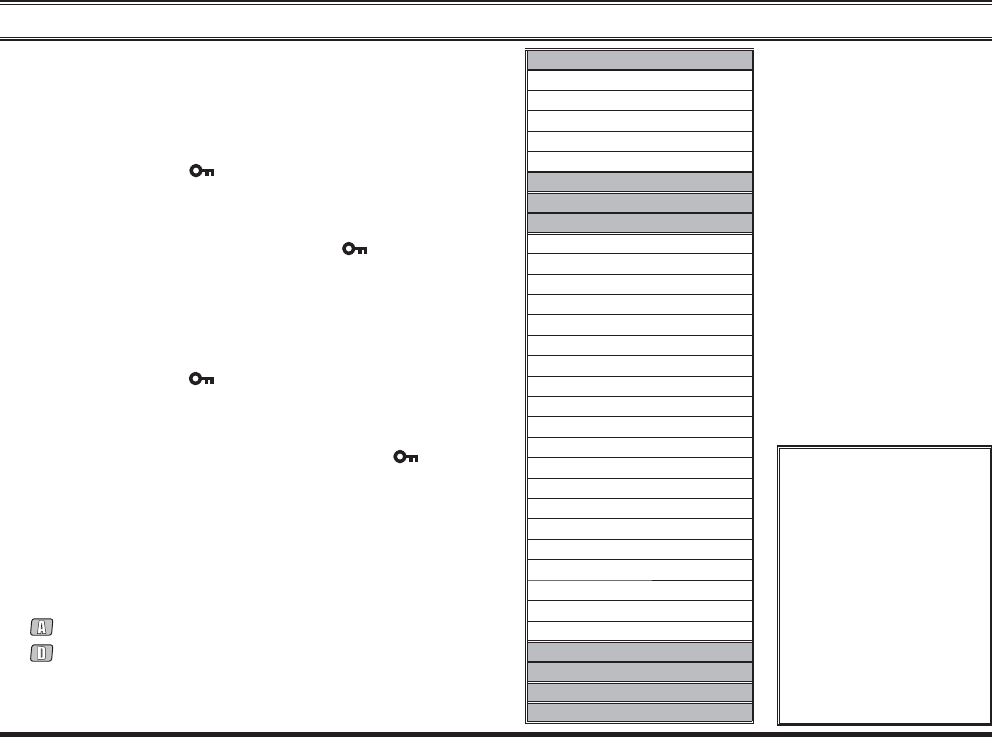
The possible setting features are listed at the right box,
and their operations are explained from next page. In this
chapter, the following icons are used to indicate item (or
feature) supported in either the “Analog” mode or “Digital”
mode:
: Indicates an “Analog” mode only feature.
: Indicates a “Digital” mode only feature.
For item (or feature) that are available in both “Analog”
and “Digital” modes, no icon is shown.
LIST
Digital Contact List
5-Tone Code Select
2-Tone Code Select
DTMF Code Select
MDC1200 ID Select
Group
Scan
Utility
Monitor
SQL OFF
Power
Minimum Volume Level
Beep
Beep Level
SQL Level
Lighting
Privacy/Encryption
Privacy Select
Lone Worker
Bell
PRI-2
TA
Scan Set/Skip
Group Scan Set/Skip
Duty
TX Save Disable
Lock Key
Lock PTT
DIAL
Message
History
LOCK
There is function which
is not called depend-
ing on the state of the
operating channel when
entering the User Set
(Menu) Mode.
For example, if you are
operating in a “Digital”
channel, the SQL SET
function has not been
recalled.
Exhibit 8: Operating Manual
FCC ID: AXI11464620
IC: 10239A-11464620
Vertex Standard LMR, Inc.
32 EVX-S24 OPERATING MANUAL
LIST
In this item, you may operate the following functions:
Digital Contact List
5-Tone Code Select
2-Tone Code Select
DTMF Code Select
MDC1200 ID Select
Press the []/[] keys to recall the function you wish to
operate, then press the [MODE()] key to activate them.
Refer to follows for detailed operation of each function.
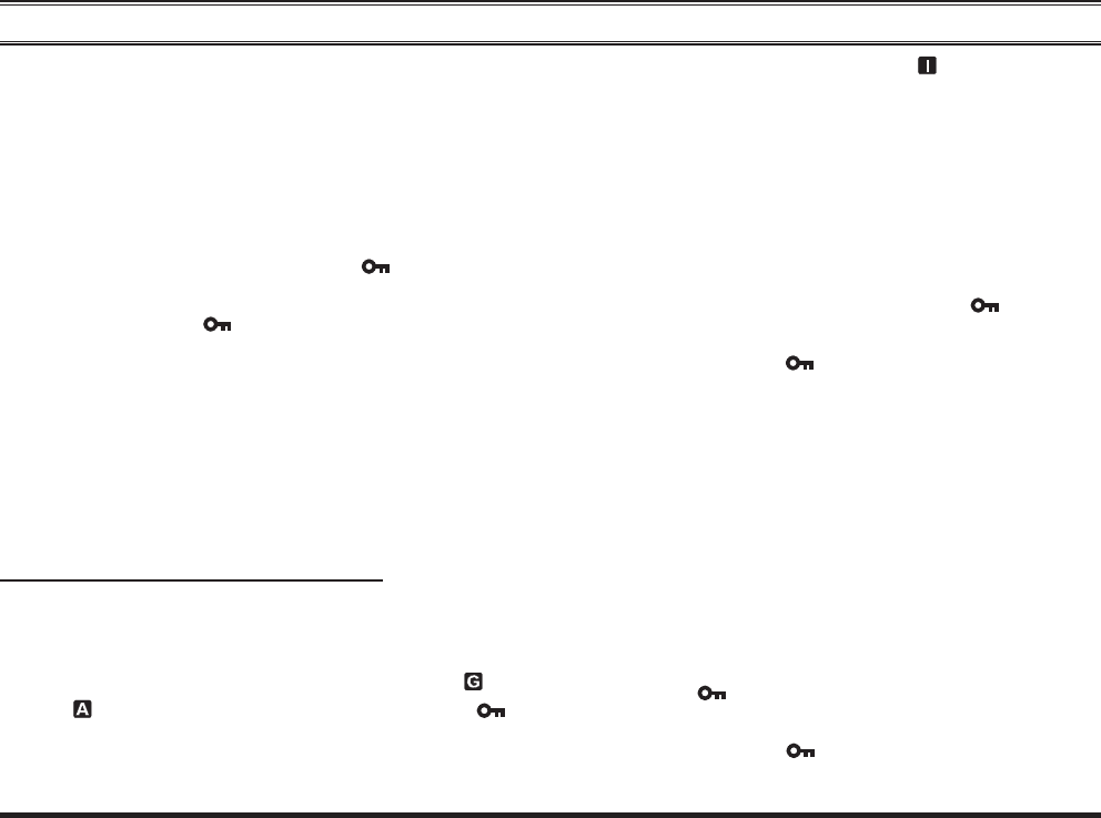
DIGITAL CONTACT LIST
Digital Contact List allows you to confirm the Contact
Alias on the Digital mode by pressing the []/[] keys.
If the TX ID Type of the selected Contact Alias is “Group
Call” or “All Call” (indicates the “ ” or “ ” icon on the
display), you may confi rm the ID code of the selected Con-
tact Alias.
If the TX ID type of the selected Contact Alias is “Indi-
vidual Call” (indicates “ ” icon on the display), you may
perform the “Call Alert”, View ID, “Radio Check”, “Radio
Enable”, or “Radio Disable” operation. See page 27 for
detail of the Digital Call operation.
USER SET (MENU) MODE
5-TONE CODE SELECT
5-Tone Code Select allows you to select/send the 5-Tone
encode code of the pre-programmed encoder list.
Press the []/[] keys to select the 5-Tone encode code,
and then press the [MODE()] key to transmit the se-
lected 5-Tone encode code.
2-TONE CODE SELECT
2-Tone Code Select allows you to select/send the 2-Tone
encode code of the pre-programmed encoder list.
Press the []/[] keys to select the 2-Tone encode code,
and then press the [MODE()] key to transmit the se-
lected 2-Tone encode code.
DTMF CODE SELECT
DTMF Code Select allows you to select/send the DTMF
Page code of the pre-programmed encoder list.
Press the []/[] keys to select the DTMF Page code,
and then press the [MODE()] key to transmit the se-
lected DTMF Page code.
MDC1200 ID SELECT
MDC1200 ID Select allows you to select the Contact
Alias on the MDC1200® Signaling feature by pressing the
[]/[] keys, and you may perform “Call Alert”, “Sel
Call”, “Radio Check”, “Stun”, and “Revive” operation.
See page 25 for detail of the MDC1200 Call operation.
Exhibit 8: Operating Manual
FCC ID: AXI11464620
IC: 10239A-11464620
Vertex Standard LMR, Inc.

EVX-S24 OPERATING MANUAL 33
GROUP
You may select a different group of channels.
Press the
[]/[] keys to recall the desired group. A
group number will appear at the upper right corner and
a group name will appear briefl y on the display.
Press the
[MODE()] key to accept the group.
SCAN
In this item, you may activate/deactivate the Scan func-
tion. Available selections are:
OFF: Stop the scan operation of the currently run-
ning.
Scan: Stop the scan operation of the currently run-
ning (if activated), and then start the Scan
operation. See page 22 for detail of the Scan
operation.
Group Scan: Stop the scan operation of the currently run-
ning (if activated), and then start the Group
Scan operation. See page 22 for detail of the
Group Scan operation.
FM Scan: Stop the scan operation of the currently run-
ning (if activated), and then start the FM
(Follow Me) Scan operation. See page 22
for detail of the Follow Me Scan operation.
Dual Watch: Stop the scan operation of the currently run-
ning (if activated), and then start the Dual
Watch operation. See page 23 for detail of
the Dual Watch operation.
TA Scan: Stop the scan operation of the currently
running (if activated), and then start the TA
(Talk Around) Scan operation. See page 24
for detail of the TA Scan operation.
USER SET (MENU) MODE
Exhibit 8: Operating Manual
FCC ID: AXI11464620
IC: 10239A-11464620
Vertex Standard LMR, Inc.
34 EVX-S24 OPERATING MANUAL
UTILITY
In this item, you may operate the following functions:
Monitor
SQL OFF
Power
Minimum Volume Level
Beep
Beep Level
SQL Level
Lighting
Privacy/Encryption
Privacy Select
Lone Worker
Bell
PRI-2
TA
Scan Set/Skip
Group Scan Set/Skip
Duty
TX Save Disable (Transmit Battery Saver Disable)
Lock Key
Lock PTT
Press the []/[] keys to recall the function you wish to
operate, then press the [MODE()] key to activate them.
Refer to follows for detailed operation of each function.
MONITOR
You may toggle the any signaling feature “On” and “Off”
by pressing the []/[] keys.
SQL OFF
You may toggle the squelch circuit “On” and “Off” by
pressing the []/[] keys.
POWER
You may toggle the radio’s transmit power “High” and
“Low” by pressing the []/[] keys.
MINIMUM VOLUME LEVEL
You may set the audio volume level when activating the
AF Min Volume function by pressing the []/[] keys.
Available selections are “0” ~ “255”.
BEEP
You may toggle the radio beeps “On” and “Off” by press-
ing the []/[] keys.
BEEP LEVEL
You may set the radio beep level by pressing the []/[]
keys. Available selections are “0” ~ “15”.
SQL LEVEL
You may select the squelch level by pressing the []/
[] keys. Available selections are “SQLLV OP (Open)”,
“SQLLV TH (Threshold)”, “SQLLV NM (Normal)” and
“SQLLV TI (Tight)”.
USER SET (MENU) MODE
Exhibit 8: Operating Manual
FCC ID: AXI11464620
IC: 10239A-11464620
Vertex Standard LMR, Inc.
EVX-S24 OPERATING MANUAL 35
LIGHTING
You may toggle the back light of the display and keypad
“On” and “Off” by pressing the []/[] keys.
PRIVACY / ENCRYPTION
You may toggle the Digital Privacy feature or Analog
Voice Inversion Encryption feature “On” and “Off” by
pressing the []/[] keys.
PRIVACY SELECT
You may select the Privacy Code for the Privacy feature
by pressing the []/[] keys. Available selections are “1”
~ “16”.
LONE WORKER
You may toggle the Lone Worker feature “On” and “Off”
by pressing the []/[] keys.
BELL
You may select the CTCSS/DCS Bell function “On” or
“Off” by pressing the []/[] keys.
When the CTCSS/DCS Bell function is set to “On”, the
alert tone activates when receive the signal including a
CTCSS or DCS tone which matches that set into your radio.
USER SET (MENU) MODE
PRI-2
You may enable/disable to set the current operating chan-
nel to the Priority Channel of the current group (Priority-2
Channel) by pressing the []/[] keys.
TA
You may toggle the Talk Around feature “On” and “Off”
by pressing the []/[] keys. See page 24 for detail of
the Talk Around feature.
SCAN SET/SKIP
You may add/delete the current channel to/from your
scanning list by pressing the []/[] keys.
GROUP SCAN SET/SKIP
You may add/delete the current group to/from your scan-
ning process by pressing the []/[] keys.
DUTY
You may toggle the Duty function “On” and “Off” by
pressing the []/[] keys. See page 29 for detail of the
Duty function.
TX SAVE DISABLE (TRANSMIT BATTERY SAVER DISABLE)
You may activate/deactivate the Transmit Battery Saver
Disable function by pressing the []/[] keys. See page
30 for detail of the Transmit Battery Saver Disable func-
tion.
Exhibit 8: Operating Manual
FCC ID: AXI11464620
IC: 10239A-11464620
Vertex Standard LMR, Inc.
36 EVX-S24 OPERATING MANUAL
LOCK KEY
You may enable/disable the Programmable Function Keys
by the Key Lock function. Available Values:
LOCK: The Programmable Function Keys will be locked
by the Key Lock function.
FREE: The Programmable Function Keys will not be
locked by the Key Lock function.
LOCK PTT
You may enable/disable the PTT switch by the Key Lock
function. Available Values:
LOCK: The
PTT switch will be locked by the Key Lock
function.
FREE: The
PTT switch will not be locked by the Key
Lock function.
DIAL
In this item, you may dial the DTMF Auto-Dial telephone
number which was pre-programmed.
Press the
[]/[] keys to select the DTMF Auto-Dial
telephone number you wish to dial.
Press the PTT switch to send a pre-defined DTMF
tone, and the DTMF tones sent during the dialing se-
quence will be heard in the speaker.
MESSAGE
The Message feature is different by the operating system.
Refer to follows for detailed operation of each operating
system.
DIGITAL MODE
Message feature on the “Digital” mode, you may receive/
send the text message from/to other radio.
Press the []/[] keys to select either of the func-
tions “INBOX” and “SEL MSG” which you want to.
INBOX: Confi rm/delete the received text message.
SEL MSG: Send the text message to other radio.
Press the [MODE()] key to accept the selected
function. Refer to follows for detailed operation of
each function.
“INBOX” function
In this function, you may confi rm/delete the received text
message.
Press the
[]/[] keys to select “INBOX”, then press
the [MODE()] key to accept it.
Press the []/[] keys to select the received text
message. The EVX-S24 can memorize up to 20 mes-
sages (fi rst-in fi rst-out basis). You may fi nd the “ALL
Delete” selection which is located at the last message
loop. Describes details of this selection in the next
paragraph.
USER SET (MENU) MODE
Exhibit 8: Operating Manual
FCC ID: AXI11464620
IC: 10239A-11464620
Vertex Standard LMR, Inc.
EVX-S24 OPERATING MANUAL 37
Press and hold in the [SIDE] key to confi rm the “Call
ID” of the selected message.
If you want to delete the selected message:
Press the
[SIDE] key again to indicate the “Delete”
selection.
Press the []/[] keys to select the “Yes”, then
press the [MODE()] key.
You may cancel the deleting the message by select-
ing the “No” instead “Yes” in the above step.
ALL Delete: You may delete the all text messages at once.
Press the []/[] keys to select the “ALL Delete”
selection which is located at the last message loop.
Press the
[]/[] keys to select the “Yes”, then press
the [MODE( )] key.
You may cancel the deleting the all text messages by
selecting the “No” instead “Yes” in the above step.
“SEL MSG” function
In this function, you may send the text message to other
radio.
Press the []/[] keys to select “SEL MSG”, then
press the [MODE()] key to accept it.
Press the
[]/[] keys to select the message you wish
to send.
Press the
[MODE( )] key to send the message.
ANALOG MODE
Message feature on the “Analog” mode, you may send
the 5-Tone status text of the pre-programmed encoder list,
and confi rm the “Message” corresponding to that received
5-Tone status text.
Sending the Message
Press the
[]/[] keys to select “SELECT”.
Press the [MODE()] key, then press the []/[]
keys to select the “Message” you wish to send.
Press the
[MODE( )] key to send the message.
Confi rm the Message
Press the
[]/[] keys to select “CHECK”.
Press the [MODE()] key, then press the []/[]
keys to select the received “Message”.
USER SET (MENU) MODE
Exhibit 8: Operating Manual
FCC ID: AXI11464620
IC: 10239A-11464620
Vertex Standard LMR, Inc.
38 EVX-S24 OPERATING MANUAL
HISTORY
In this item, you may confi rm the history of the received
station’s ID of the operating system which set to the cur-
rent operating channel. Available operating system are
Digital ID, 5-Tone ID, DTMF ID, and MDC1200® ID.
Press the
[]/[] keys to scroll the received station’s
ID of the operating system which set to the current op-
erating channel.
Press and hold in the [SIDE] key to indicate the
“Channel Tag (Name)” which received that station’s
ID, if desired.
USER SET (MENU) MODE
LOCK
In this item, you may lock the Programmable keys and
PTT switch to prevent accidental channel change or inad-
vertent transmission.
To locked out the key locking, press and hold the
[MODE()] key.
You may change the lockout confi guration by the “Lock
Key” and “Lock PTT” functions in the “Utility” item of
this “User Set (Menu)” mode. See page 36 for more infor-
mation.
Exhibit 8: Operating Manual
FCC ID: AXI11464620
IC: 10239A-11464620
Vertex Standard LMR, Inc.
EVX-S24 OPERATING MANUAL 39
OPTIONAL ACCESSORIES
FNB-V142LI
3.7V DC
, 2300 mAh Li-Ion Battery Pack
PA-57B/C/U/F/G/H/K AC Adapter (charge only)
CD-65 Charger Stand (requires the PA-57 AC Adapter)
CD-66 Dual Battery Single Unit Charger (requires the PA-57 AC Adapter)
MH-89A4B Earpiece Microphone
ATU-6A UHF Antenna (400-430 MHz)
ATU-6B UHF Antenna (420-450 MHz)
ATU-6C UHF Antenna (440-470 MHz)
ATU-6D UHF Antenna (450-485 MHz)
ATU-20AS UHF Stubby Antenna (400-430 MHz)
ATU-20CS UHF Stubby Antenna (420-450 MHz)
ATU-20DS UHF Stubby Antenna (440-470 MHz)
ATU-20FS UHF Stubby Antenna (450-480 MHz)
CLIP-27 Belt Clip
CE157 PC Programming Software
CB000262A01 Micro USB Programming Cable
: “B” suffi x is for USA, “C” suffi x is for EU, “U” suffi x
is for UK, “F” suffi x is for Argentina, “G” suffi x is for
China, “H” suffi x is for Australia, and “K” suffi x is for
Brazil.
Always use Vertex Standard authorized acces-
sories. Vertex Standard shall not be liable for
any damage or accidents such as fi re, leakage
or explosion batteries, etc., caused by the mal-
function of non-Vertex Standard accessories.
Availability of accessories may vary; some
accessories are supplied standard per local
requirements, others may be unavailable in
some regions. Check with your Vertex Stan-
dard Dealer for changes to this list.
Exhibit 8: Operating Manual
FCC ID: AXI11464620
IC: 10239A-11464620
Vertex Standard LMR, Inc.

40 EVX-S24 OPERATING MANUAL
WARRANTY POLICY
Vertex Standard warrants, to the original purchaser only, its Vertex Standard manufactured communications products
against defects in materials and workmanship under normal use and service for a given period of time from the date of pur-
chase.
Limited Warranty Details:
North America customers (USA and Canada): http://www.vertexstandard.com/lmr/warranty-terms.aspx
Customers outside of North America: contact the authorized Vertex Standard distributor in your country.
Exhibit 8: Operating Manual
FCC ID: AXI11464620
IC: 10239A-11464620
Vertex Standard LMR, Inc.
Part 15.21: Changes or modifi cations to this device not expressly approved by Vertex Standard could void the user’s
authorization to operate this device.
The AMBE+2™ voice coding Technology embodied in this product is protected by intellectual property rights in-
cluding patent rights, copyrights and trade secrets of Digital Voice Systems, Inc. This voice coding Technology is
licensed solely for use within this Communications Equipment. The user of this Technology is explicitly prohibited
from attempting to decompile, reverse engineer, or disassemble the Object Code, or in any other way convert the
Object Code into a human-readable form.
U.S. Pat. Nos. #5,870,405, #5,826,222, #5,754,974, #5,701,390, #5,715,365, #5,649,050, #5,630,011, #5,581,656,
#5,517,511, #5,491,772, #5,247,579, #5,226,084 and #5,195,166.
DISPOSAL OF YOUR ELECTRONIC AND ELECTRIC EQUIPMENT
Products with the symbol (crossed-out wheeled bin) cannot be disposed as household waste.
Electronic and Electric Equipment should be recycled at a facility capable of handling these items and
their waste by products.
In EU countries, please contact your local equipment supplier representative or service center for informa-
tion about the waste collection system in your country.
Exhibit 8: Operating Manual
FCC ID: AXI11464620
IC: 10239A-11464620
Vertex Standard LMR, Inc.

No portion of this manual may be reproduced without the per-
mission of Vertex Standard LMR, Inc.
Vertex Standard is a trademark of Vertex Standard LMR, Inc.
All other trademarks are the property of their respective owners.
©2016 Vertex Standard LMR, Inc.
All rights reserved.
Vertex Standard LMR, Inc.
4-6-8 Shibaura, Minato-ku, Tokyo 108-0023, Japan
Exhibit 8: Operating Manual
FCC ID: AXI11464620
IC: 10239A-11464620
Vertex Standard LMR, Inc.