Vieworks FXRS-03A System Control Unit User Manual VIVIX S 1012N V1 0W16 EN
Vieworks Co., Ltd. System Control Unit VIVIX S 1012N V1 0W16 EN
UserManual.wiki
>
Vieworks
>
FXRS-03A User Manual
>
User Manual 2
Contents
1.
User Manual
2.
User Manual 1
3.
User Manual 2
User Manual 2
Navigation menu
Upload a User Manual
Namespaces
Wiki Guide
HTML
PDF
Info
Views
User Manual
Discussion / Help
Navigation
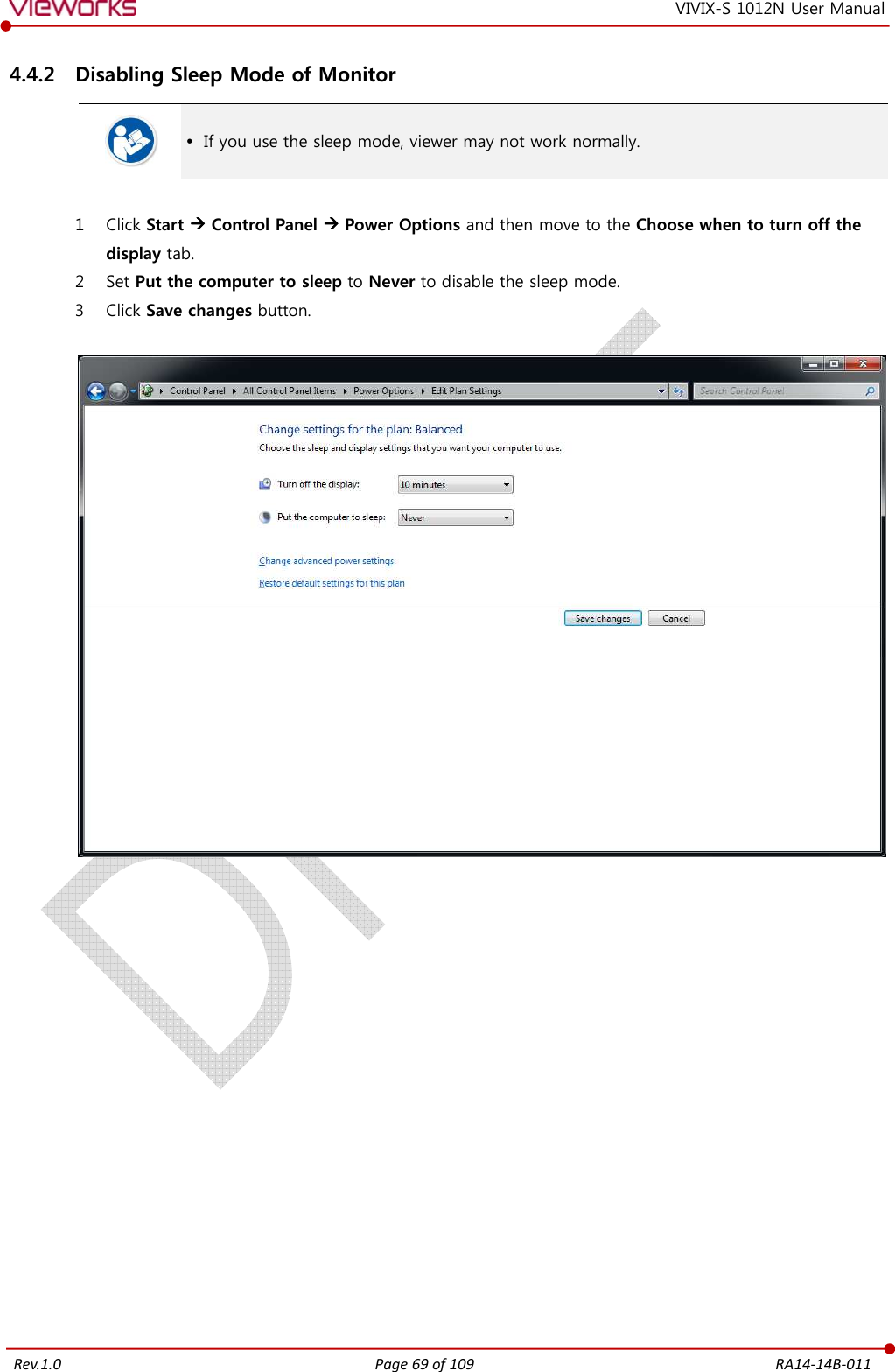
![Rev.1.0 Mini SCU [TBD] 1 If you use the DR Triggerof SCU, and the other to the X If you use the AED mode, a generator interface cable is not needed as the detector operates by detecting X 2 Connect one end of the LAN Connector of workstation assigned 3 To transmit image data using a Tether Interfathe port of Mini SCU and the other to the detecto If you use the wireless communication method, a tether interface cable is not needed as the image is transmitted wirelessly. 4 To supply power, connect the Page 61 of 109 VIVIXDR Trigger mode, connect the one end of generator interface cable to the of SCU, and the other to the X-ray generator. If you use the AED mode, a generator interface cable is not needed as the detector operates by detecting X-ray automatically. LAN cable to one of the LAN ports of SCU, and the other to the LAN Card Connector of workstation assigned for data transfer. To transmit image data using a Tether Interface, connect the one end of the tether SCU and the other to the detector. If you use the wireless communication method, a tether interface cable is not needed as image is transmitted wirelessly. To supply power, connect the DC power cable to the DC power input port of SCURA14-14B-011 VIX-S 1012N User Manual onnect the one end of generator interface cable to the EXT_INF port If you use the AED mode, a generator interface cable is not needed as the detector of SCU, and the other to the LAN Card ether interface cable to If you use the wireless communication method, a tether interface cable is not needed as port of SCU.](https://usermanual.wiki/Vieworks/FXRS-03A.User-Manual-2/User-Guide-2532561-Page-1.png)
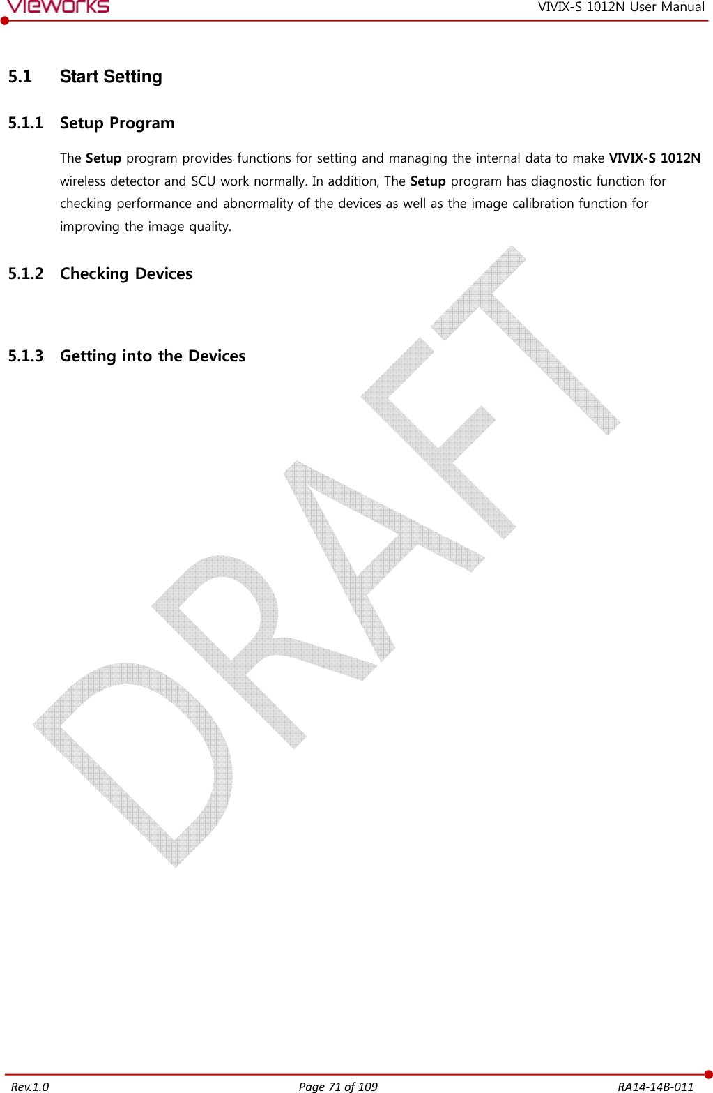
![Rev.1.0 Page 63 of 109 RA14-14B-011 VIVIX-S 1012N User Manual 4.2.4 Checking Status LED of Detector [TBD] Power LED The power LED indicates the power status information which is permitted to the detector in green. The power LED lights up when the power is permitted normally. If the detector is connected with a tether interface, the power LED lights up when power is permitted to SCU because the detector is supplied power from SCU. The power LED is blinking when the detector is in the sleep mode. Active LED The active LED indicates status information about the possibility that the detector can be used normally or not in orange. The active LED is blinking when the detector is completed to boot up normally. If the detector AP is on, the LED blinks for 5 times right after the booting. Data LED The data LED indicates status information about the data processing in blue. The data LED lights up when the detector is available to make data communication. If the detector is in the sleep mode, the data LED lights up. The data LED is blinking while the detector transmits or saves data. If the detector AP is on, the LED blinks for 5 times right after the booting. Summary List of Detector Status LED Information Power lamp Active lamp Data lamp Color Green Orange Blue When power is permitted On Off Off Boot-up completed (AP ON) On Blinking 5 times Blinking 5 times Boot-up completed (AP OFF) On On Off Ready for communication On On On Sleep mode Blinking On On Data communication (Send or Store) On On Blinking In process of wireless initialization On Blinking Off Power Off Off Off Off If the LED blinks abnormally, refer to <Troubleshooting> to check if communication or system error is occurred.](https://usermanual.wiki/Vieworks/FXRS-03A.User-Manual-2/User-Guide-2532561-Page-3.png)
![Rev.1.0 Page 64 of 109 RA14-14B-011 VIVIX-S 1012N User Manual 4.3 Software Installation This section gives information about how to install the software on the workstation (PC) and how to configure the environment for software operation and communication. Check suitability of acquiring, processing and adjusting of images by referring to the recommended workstation specifications before the software installation. 4.3.1 Software Classification [TBD] Vieworks provides clients who purchase our detector system with software as below. You can choose and use one of our softwares below. Software Description VXvue A program for acquiring and adjusting images developed by Vieworks. Used for ViVIX-S detectors only. Unnecessary to develop a separate viewer program. VIVIX Setup A program for setting and managing the detector and SCU. VXvue (Viewer) Software for acquiring, adjusting and managing the image. XIPL Image processing program Document VXvue Operation Manual XIPL User Manual VIVIX SDK Software development kit for ViVIX-S detector only, provided by Vieworks. You can develop your own software dedicated to ViVIX-S by using this kit. SDK Package Development package VIVIX Setup A program for acquiring, adjusting and managing the image. Document VIVIX SDK Developer Manual 4.3.2 Software Installation For a client who uses VXvue, install the VXvue program after reading VXvue Operation Manual carefully. For a client who uses VIVIX SDK, install the Setup program after reading VIVIX SDK Developer Manual. Be sure to install the software first with reading this manual before configuring Windows environment. Apart from the detector and SCU, the software can be installed separately.](https://usermanual.wiki/Vieworks/FXRS-03A.User-Manual-2/User-Guide-2532561-Page-4.png)
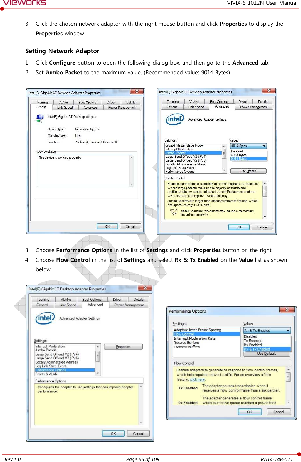
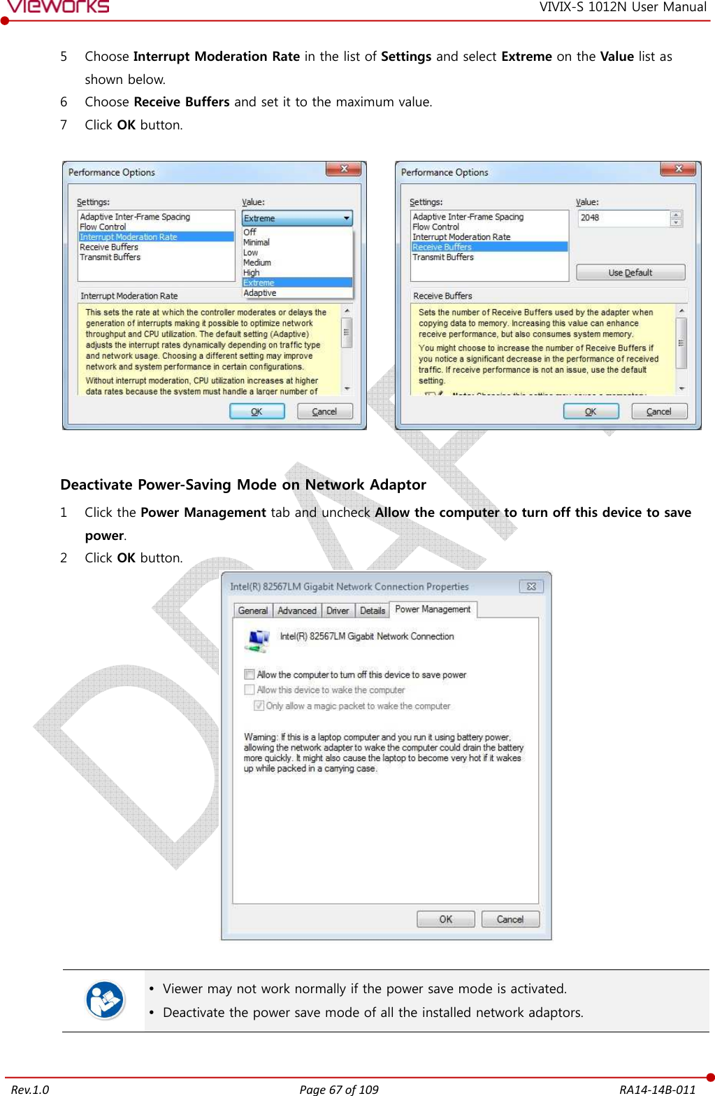
![Rev.1.0 Page 65 of 109 RA14-14B-011 VIVIX-S 1012N User Manual 4.4 Windows Environment Setting This section gives information about configuring Windows to communicate with the detector and SCU after installing the Setup program or Viewer. The contents in this chapter are made on the basis of Windows 7. Configuration environment can be different depending on network adaptor manufacturer or models. 4.4.1 Network Configuration [TBD] Communication disruption between the detector (Or SCU) and workstation occurs unless the network adaptor is proper is set properly, it may cause serious repercussion to the product and image quality. Selecting Network Adaptor 1 Click Start Control Panel Network and Internet Network and Sharing Center Change Adapter Setting. 2 Choose the networks adaptor for communicating with the detector and SCU, and then rename it. It is recommended to change the name of network adaptor to distinguish it from other connection names. Even though the name is changed, it will not affect to the operation and communication performance of the equipment.](https://usermanual.wiki/Vieworks/FXRS-03A.User-Manual-2/User-Guide-2532561-Page-5.png)
![Rev.1.0 Page 70 of 109 RA14-14B-011 VIVIX-S 1012N User Manual 5. Setting [TBD] This section gives information about the product setting with using the Setup program. Start Setting VIVIX SCU Setting Detector Setting](https://usermanual.wiki/Vieworks/FXRS-03A.User-Manual-2/User-Guide-2532561-Page-10.png)
![Rev.1.0 Page 74 of 109 RA14-14B-011 VIVIX-S 1012N User Manual 6. Calibration [TBD] This chapter gives information about the calibration methods after installing a detector. Calibration Dialogue Detector Configuration Calibration Guide Calibrating by Loading the Calibration Data Direct Calibration](https://usermanual.wiki/Vieworks/FXRS-03A.User-Manual-2/User-Guide-2532561-Page-14.png)

![Rev.1.0 Page 78 of 109 RA14-14B-011 VIVIX-S 1012N User Manual 6.4 Calibrating by Loading the Calibration Data Vieworks provides the offset calibration data as a CD with the detector. However, we recommend the service enginner to carry out the calibration by oneself as the detector condition can be different by the operating method or use environment. 6.4.1 Preparing Calibration Data 1 Prepare the calibration data CD provided with the detector. 2 Copy the calibration data files and save them to a safe route such as local HDD. The calibration data CD is consisted of 4 data files as below. File Description Pre-Offset Detector Offset data 1 Post-Offset Detector Offset data 2 Gain Offset Image sensitivity Offset data Defect Map Defect calibration map data Each name of a data file is made with the combination of rules as follows. [Serial number]_[ Calibration data name].dat ](https://usermanual.wiki/Vieworks/FXRS-03A.User-Manual-2/User-Guide-2532561-Page-18.png)
![Rev.1.0 Page 80 of 109 RA14-14B-011 VIVIX-S 1012N User Manual 7. Diagnosis, Inspection and Maintenance [TBD] This section gives information about diagnosis, inspection & maintenance of the product. Diagnosis Product Inspection Cleaning and Disinfection Product Initialization Replacing the Fuse of VIVIX SCU](https://usermanual.wiki/Vieworks/FXRS-03A.User-Manual-2/User-Guide-2532561-Page-20.png)
![Rev.1.0 Page 81 of 109 RA14-14B-011 VIVIX-S 1012N User Manual 7.1 Diagnosis 7.1.1 Image Diagnosis Check the image quality through Diagnosis tools after installing the detector or before usage. If the problems with regard to products or image occur during diagnosis, try to do a calibration again. If the problems are not solved, consult the sales representative in Vieworks or a service engineer. You can acquire and review an image from the Diagnosis window in Setup program. You can review images by acquiring them through real exposure or getting Dark image by clicking Get Normal Image button. The number of images, pixel value and ROI value will be displayed. The effective area or whole area of an image can be checked. It is also available to check the image by changing its direction. Save the reviewed image as a raw one to analyze. You can acquire an image either applying Offset / Gain data or not. 7.1.2 Battery Pack Diagnosis Install the battery pack to the detector and check the voltage and remaining amount of the battery pack. Furthermore, always check the remaining amount of the battery pack during use of the detector. If performance of the battery pack has some problems, consult the sales representative in Vieworks or a relevant engineer. The battery pack belongs to consumables which performance will be decreased as time passed. Make sure to check the battery life during usage. Check Voltage of Battery Pack [TBD] Check remaining amout of battery pack 7.1.3 Wireless Communication Diagnosis In case of using the detector with wireless communication way, make sure to check the status of wireless communication before starting to use. If the status of wireless communication is bad, the speed of acquiring images will be very slow or failed to acquire images. Try to check the surrounding wireless communication status not to occur communication interference. If wireless communication module in the detector has problems, consult the sales representative in Vieworks or a relevant engineer.](https://usermanual.wiki/Vieworks/FXRS-03A.User-Manual-2/User-Guide-2532561-Page-21.png)

![Rev.1.0 Page 89 of 109 RA14-14B-011 VIVIX-S 1012N User Manual 8. Troubleshooting [TBD] This section gives information about troubleshooting. Troubleshooting](https://usermanual.wiki/Vieworks/FXRS-03A.User-Manual-2/User-Guide-2532561-Page-29.png)

![Rev.1.0 Page 97 of 109 RA14-14B-011 VIVIX-S 1012N User Manual 9.2 Radio Frequency Compliance Information Country Item U.S.A FCC Part 15.107 Subpart (b) / 15.109(g) Subpart B FCC Part 15 Subpart E 15.407 FCC Part 15 Subpart C 15.247 European Union [TBD] South Korea Clause 3, Article 58-2 of Radio Waves Act Clause 2, Article 58-2 of Radio Waves Act Japan Article 2-1-19, 2-1-19-3, 2-1-19-3-2 of the Radio law (MIC) 9.2.1 FCC Compliance This equipment has been tested and found to comply with the limits for a Class B digital device, pursuant to part 15 of FCC Rules. These limits are designed to provide reasonable protection against harmful interference in a residential installation. Operation is subject to the following tow conditions. This device may not cause harmful interference. This device must accept any interference received, including interference that may cause undesired operation. This equipment generates, uses, and can radiate radio frequency energy and, if not installed and used in accordance with the instruction, may cause harmful interference to radio communications. However, there is no guarantee that interference will not occur in a particular installation. If this equipment does cause harmful interference to radio or television reception, which can be determined by turning the equipment off and on, the user is encouraged to try to correct the interference by one or more of the following measure. Reorient or relocate the receiving antenna. Increase the separation between the equipment and receiver. Connect the equipment into an outlet on a circuit different from where the receiver is connected. Consult the distributor or an experienced radio/TV technician for help. Change or modification which is not expressly approved by the party responsible for compliance could void the user’s authority to operate the equipment. 5.15-5.35G㎐ band is restricted to indoor operations only. The SAR limit set by the FCC is 1.6 W/kg. The highest SAR value for this model when tested for use at the front is 0.568 W/kg. The front side of a detector should be used for image acquisition.](https://usermanual.wiki/Vieworks/FXRS-03A.User-Manual-2/User-Guide-2532561-Page-37.png)
![Rev.1.0 Page 98 of 109 RA14-14B-011 VIVIX-S 1012N User Manual 9.3 Labels and Symbols The ViVIX-S 1012N detector and relevant components have labels attached on them. The contents and locations of each label are indicated below. 9.3.1 Label Detector [TBD] Battery [TBD]](https://usermanual.wiki/Vieworks/FXRS-03A.User-Manual-2/User-Guide-2532561-Page-38.png)
![Rev.1.0 Page 99 of 109 RA14-14B-011 VIVIX-S 1012N User Manual VIVIX SCU (VIVIX System Control Unit) [TBD] Battery Charger [TBD]](https://usermanual.wiki/Vieworks/FXRS-03A.User-Manual-2/User-Guide-2532561-Page-39.png)
![Rev.1.0 Page 100 of 109 RA14-14B-011 VIVIX-S 1012N User Manual Outer Box [TBD] 9.3.2 Product Serial Number Serial Number Composition The serial numbers for each product or accessory are composed as follows. 1 0 - R 1 D A B J 0 0 1 Revision - Item Composition Year Month Serial number Revision will be updated in case of follows. Mass production or a large amount of order. Exterior alteration. Item code will be produced based on internal management standard of vieworks. Composition code is like follows. D: Detector S: VIVIX SCU C: Battery Charger Range of Serial Number is 001 ~ 999. Initial Per Year 11 12 13 14 15 16 17 18 19 20 AA AB AC AD AE AF AG AH AI BJ Initial Per Month 1 2 3 4 5 6 7 8 9 10 11 12 A B C D E F U V W X Y Z Composition of Serial Number for Each Item [TBD] Model Composition Serial Number 1012NA Detector 10-V5D?? 1012NB Detector 10-V6D?? FXRC-02A Battery Charger 10-V5C?? FXRS-04A VIVIX SCU 10-V5S??](https://usermanual.wiki/Vieworks/FXRS-03A.User-Manual-2/User-Guide-2532561-Page-40.png)
![Rev.1.0 Page 105 of 109 RA14-14B-011 VIVIX-S 1012N User Manual Conducted RF IEC 61000-4-6 / Radiated RF IEC 61000-4-3 Item Description Immunity test Conducted RF IEC 61000-4-6 Radiated RF IEC 61000-4-3 IEC 60601 test condition 3 Vrms 150 ㎑ to 80 ㎒ 3 V/m 80 ㎒ to 2.5 ㎓ Compliance Level 3 Vrms 150 ㎑ to 80 ㎒ 3 V/m 80 ㎒ to 2.5 ㎓ Electromagnetic Environment - Guidance Portable and mobile RF communications equipment should be used no closer to any part of the EUT, including cables, than the recommended separation distance calculated from the below equations applicable to the frequency of the transmitter. P is the maximum output power rating of the transmitter in watts (W) according to the transmitter manufacturer and d is the recommended separation distance in meters (m). Field strengths from fixed RF transmitters, as determined by an electromagnetic site surveya, should be less than the compliance level in each frequency range b. Interference may occur in the vicinity of equipment marked with the symbol. At 80 ㎒ and 800 ㎒, the higher frequency range applies. These guidelines may not apply in all situations. Electromagnetic propagation is affected by absorption and reflection from structures, objects and people. Field strengths from fixed transmitters, such as base stations for radio (cellular/cordless) telephones and land mobile radios, amateur radio, AM and FM radio broadcast and TV broadcast cannot be predicted theoretically with accuracy. To assess the electromagnetic environment due to fixed RF transmitters, an electromagnetic site survey should be considered. If the measured field strength in the location in which EUT is used exceeds the applicable RF compliance level above, EUT should be observed to verify normal operation. If abnormal performance is observed, additional measures may be necessary, such as reorienting or relocating EUT. Over the frequency range 150 ㎑ to 80 ㎒, field strengths should be less than [V1] V/m.](https://usermanual.wiki/Vieworks/FXRS-03A.User-Manual-2/User-Guide-2532561-Page-45.png)