Westell 7502AGXX-00 Home Monitoring Gateway User Manual 1
Westell Inc Home Monitoring Gateway 1
Westell >
Contents
- 1. User Manual1
- 2. User Manual2
- 3. User Manual 1
- 4. User Manual 2
User Manual1

Copyright © 2009 Westell, Inc 030-300589 Rev. A
CONTROL POINT HOME MONITORING SERVICE
USER GUIDE

030-300589 Rev. A 2 March 2009
User Guide Control Point Home Monitorin
g
Service
TABLE OF CONTENTS
1. PRODUCT DESCRIPTION ..................................................................................................................................3
2. SAFETY INSTRUCTIONS ...................................................................................................................................4
3. REGULATORY INFORMATION ........................................................................................................................5
3.1 FCC Compliance Note...............................................................................................................................5
3.2 Canada Certification Notice.......................................................................................................................6
4. MINIMUM REQUIREMENTS .............................................................................................................................7
5. HARDWARE FEATURES....................................................................................................................................8
5.1 LED Indicators...........................................................................................................................................8
5.2 Rear Panel Components.............................................................................................................................9
6. INSTALLING THE HARDWARE......................................................................................................................10
6.1 Installation Requirements ........................................................................................................................10
6.2 Before you begin......................................................................................................................................10
6.3 Installations..............................................................................................................................................11
7. USING THE SETUP WIZARD...........................................................................................................................14
7.1 Before You Begin ....................................................................................................................................14
7.2 Starting the Setup Wizard ........................................................................................................................16
7.3 Creating Your Control Point Account......................................................................................................18
7.4 Activating Your Control Point.................................................................................................................21
7.5 Setting Up Your 7521FF Camera ............................................................................................................27
8. ACCESSING YOUR CONTROL POINT USER INTERFACE .........................................................................34
9. HOME ..................................................................................................................................................................35
9.1 Creating Widgets and Tabs......................................................................................................................36
9.2 Using the Administrator Links.................................................................................................................37
10. CONTROL ...........................................................................................................................................................38
10.1 Devices.....................................................................................................................................................38
10.2 Rooms ......................................................................................................................................................40
10.3 Scenes ......................................................................................................................................................42
10.4 Sensors.....................................................................................................................................................43
10.5 Schedule...................................................................................................................................................45
11. MONITOR ...........................................................................................................................................................47
11.1 Display Panel ...........................................................................................................................................47
11.2 Filmstrip Panel.........................................................................................................................................50
12. TECHNICAL SUPPORT INFORMATION ........................................................................................................51
13. PRODUCT SPECIFICATIONS...........................................................................................................................51
14. SOFTWARE LICENSE AGREEMENT..............................................................................................................52
15. PUBLICATION INFORMATION.......................................................................................................................54

030-300589 Rev. A 3 March 2009
User Guide Control Point Home Monitorin
g
Service
1. PRODUCT DESCRIPTION
The Westell® Control Point Home Monitoring Service is a reliable system that allow you to monitor and control
electronic and wireless devices throughout your home.
This User Guide is intended to provide information on installing and using your Westell® Control Point Home
Monitoring Service and assumes the user of this system has medium to advanced knowledge of networking devices.
To use this product you must have a router or gateway installed and functioning properly on your network along
with active Internet service. Please read all instructions in this User Guide before proceeding with this installation.
The Westell Control Point Home Monitoring devices are powered by ENERGY STAR® qualified adapters.
030-300589 Rev. A 4 March 2009
User Guide Control Point Home Monitorin
g
Service
2. SAFETY INSTRUCTIONS
Please practice general safety precautions when installing any electrical device. Please read and save the following
important safety notes before installing your device:
• Do not use this product near water, for example, near a bathtub, washbowl, kitchen sink or laundry tub, in a
wet basement or near a swimming pool.
• Avoid using a telephone (other than a cordless type) during an electrical storm. There may be a remote risk
of electric shock from lightning.
• Do not use the telephone to report a gas leak in the vicinity of the leak.
• Do not connect this equipment in an environment that is unsuitable.
• Never install any telephone wiring during a lightning storm.
• Never install telephone jacks in wet locations unless the jack is specifically designed for wet locations.
• Never touch non-insulated telephone wires or terminals unless the telephone line has been disconnected at
the network interface.
• Use caution when installing or modifying telephone lines.
WARNING
Risk of electric shock. Voltages up to 140 Vdc (with reference to
ground) may be present on telecommunications circuits.

030-300589 Rev. A 5 March 2009
User Guide Control Point Home Monitorin
g
Service
3. REGULATORY INFORMATION
3.1 FCC Compliance Note
This equipment has been tested and found to comply with the limits for a Class B digital device, pursuant to Part 15
of the Federal Communication Commission (FCC) Rules. These limits are designed to provide reasonable protection
against harmful interference in a residential installation. This equipment generates, uses, and can radiate radio
frequency energy, and if not installed and used in accordance with the instructions, may cause harmful interference
to radio communications. However, there is no guarantee that interference will not occur in a particular installation.
If this equipment does cause harmful interference to radio or television reception, which can be determined by
turning the equipment Off and On, the user is encouraged to try to correct the interference by one or more of the
following measures:
• Reorient or relocate the receiving antenna.
• Increase the separation between the equipment and the receiver.
• Connect the equipment to a different circuit from that to which the receiver is connected.
• Consult the dealer or an experienced radio/TV technician for help.
• This device complies with part 15 of the FCC Rules. Operation is subject to the following two conditions:
(1) this device may not cause harmful interference, and (2) this device must accept any interference
received, including interference that may cause undesired operation.
WARNING: While this device is in operation, a separation distance of at least 20 cm (8 inches) must be maintained
between the radiating antenna and users exposed to the transmitter in order to meet the FCC RF exposure guidelines.
Making changes to the antenna or to the device is not permitted. Doing so may result in the installed system
exceeding RF exposure requirements. This device must not be co-located or operated in conjunction with any other
antenna or radio transmitter. Installers and end users must follow the installation instructions provided in this guide.
Modifications made to the product, unless expressly approved, could void the users’ rights to operate the
equipment.
User Guide Control Point Home Monitorin

030-300589 Rev. A 6 March 2009
Service
3.2 Canada Certification Notice
The Industry Canada label identifies certified equipment. This certification means that the equipment meets certain
telecommunications network protective, operations and safety requirements as prescribed in the appropriate
Terminal Equipment Technical Requirements document(s). The department does not guarantee the equipment will
operate to the user’s satisfaction.
This equipment meets the applicable Industry Canada Terminal Equipment Technical Specification. This is
confirmed by the registration number. The abbreviation, IC, before the registration number signifies that registration
was performed based on a Declaration of Conformity indicating that Industry Canada technical specifications were
met. It does not imply that Industry Canada approved the equipment. The Ringer Equivalence Number (REN) is 0.0.
The Ringer Equivalence Number that is assigned to each piece of terminal equipment provides an indication of the
maximum number of terminals allowed to be connected to a telephone interface. The termination on an interface
may consist of any combination of devices subject only to the requirement that the sum of the Ringer Equivalence
Numbers of all the devices does not exceed five.
Before installing this equipment, users should ensure that it is permissible to be connected to the facilities of the
local Telecommunication Company. The equipment must also be installed using an acceptable method of
connection. The customer should be aware that compliance with the above conditions may not prevent degradation
of service in some situations. Connection to a party line service is subject to state tariffs. Contact the state public
utility commission, public service commission, or corporation commission for information.
If your home has specially wired alarm equipment connected to the telephone line, ensure that the installation of this
equipment (Model 7502AG) does not disable your alarm equipment. If you have questions about what will disable
alarm equipment, consult your telephone company or a qualified installer.
If you experience trouble with this equipment (Model 7502AG), do not try to repair the equipment yourself. The
equipment cannot be repaired in the field and must be returned to the manufacturer. Repairs to certified equipment
should be coordinated by a representative, and designated by the supplier. Contact your service provider for
instructions. The termination on an interface may consist of any combination of devices subject only to the
requirement that the sum of the Ringer Equivalence Numbers of all the devices does not exceed five.
Users should ensure, for their own protection, that the electrical ground connections of the power utility, telephone
lines, and internal, metallic water pipe system, if present, are connected together. This precaution may be
particularly important in rural areas.
CAUTION
Users should not attempt to make such connections themselves, but should contact the
appropriate electrical inspection authority, or electrician, as appropriate.
User Guide Control Point Home Monitorin

030-300589 Rev. A 7 March 2009
User Guide Control Point Home Monitorin
g
Service
4. MINIMUM REQUIREMENTS
To network your 7502AG Control Point, please confirm that you have a gateway or router with an available
10/100 BaseT Ethernet port connected to your network that has active Internet service.
To activate and configure your Control Point services, please confirm that you have the following minimum
computer requirements:
• Pentium® or higher class machines
• Microsoft® Windows® Vista™ or Macintosh® OS X or later
• 64 MB RAM (128 MB recommended)
• 10 MB of free hard drive space
• 10/100 Base-T Network Interface Card (NIC)
• Explorer® 7.0 or later, Firefox® 3.0, or later, Safari® 2.0 or later
To stream video from your 7521FF Camera to your browser, you will need a version (6 or later) of the QuickTime®
media player installed. You will be instructed to install QuickTime® at the end of the Setup Wizard—if you do not
already have it installed.

030-300589 Rev. A 8 March 2009
User Guide Control Point Home Monitorin
g
Service
5. HARDWARE FEATURES
5.1 LED Indicators
LED indicators are located on the front of your 7502AG and 7521FF devices and are used to verify each unit’s
operation and status. This section explains the LED states and descriptions.
7502AG LED States and Descriptions
LED State Description
Solid Green Control Point is powered On.
Solid Red POST (Power On Self Test), Failure (not bootable) or Device
Malfunction. Note: The Control Point Power LED should be red no
longer than two seconds after the power on self test passes.
POWER
Off Control Point is powered Off, or no power is present.
Solid Green USB device detected, LAN activity present (traffic in either direction).
USB link established.
USB1
USB2
Off Control Point is powered Off, No USB device detected, No USB link
established.
Solid Green Ethernet link is established. Transmit or Receive Activity is present on
the Ethernet interface.
ETHERNET
Off Control Point is powered Off, No Ethernet link is established.
Solid Green Wireless link established. Wireless LAN activity is present (traffic in
either direction).
Flashing Green Wireless link is being established.
WIFI
Off Control Point is powered Off, or No Link established
Solid Green
Internet link established. The Control Point has a WAN IP address
from IPCP or DHCP; or a static IP is configured.
IP connection established and IP Traffic is passing through device (in
either direction.
INTERNET
Off No Internet link established.
Solid Green Control Point has detected a Z-Wave device, Connection is established,
via wired or wirelessly.
Z-Wave Off Control Point is powered Off, Control Point has not detected a Z-Wave
device on the network (via wired or wireless connection).
Solid Green Control Point has been Activated. Connection established with Control
Point’s portal server, Control Point is passing traffic to the portal
server.
Flashing Green Control Point is in Activation Mode.
SERVICE
Off Control Point is powered Off, No connection established with the
portal server.
7521FF IP Camera LED States and Descriptions
LED State Description
Solid Green Camera is powered On.
Flashing Green Camera is in power on mode.
Power
Off Camera is powered Off, or no power is present.
Solid Green Camera has established a connection with the Control Point.
Flashing Green Camera is connecting to Control Point, or Camera is send data.
Network
Off Camera is powered Off, or no network connection established.
030-300589 Rev. A 9 March 2009
User Guide Control Point Home Monitorin
g
Service
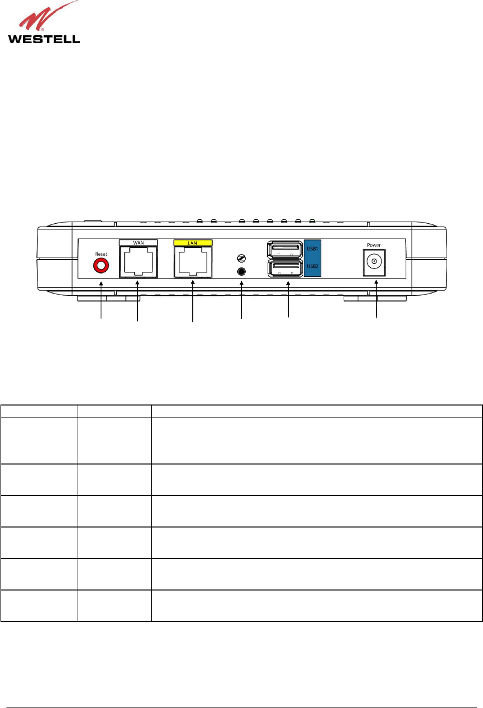
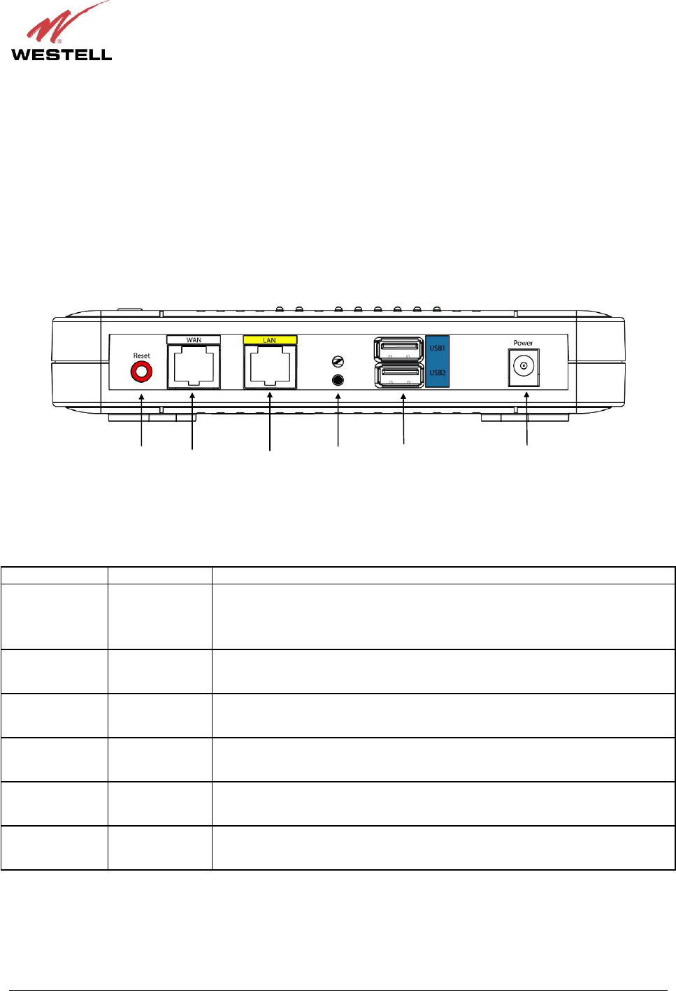
5.2 Rear Panel Components
• Reset button
• 10/100 Base-T Ethernet connector (WAN)
• 10/100 Base T Ethernet connector (LAN))
• Z-Wave push button
• USB connectors (USB1/USB2)
• Power connector
7502AG – Rear Panel
The following table describes the 7502AG Control Point rear panel components.
NAME TYPE FUNCTION
Reset
Recessed push
button
Allows you to reboot the 7502AG or to restore the 7502AG to factory default
configuration settings. If pressed for less than 5 seconds, the device will reboot.
If pressed more than 10 seconds, the device will be restored to factory default
settings.
WAN 8-pin (RJ-45)
modular jack
Connects the 7502AG to a gateway on your existing network, enabling access
to Control Point services via the Internet or Wide Area Network (WAN).
LAN 8-pin (RJ-45)
modular jack Connects the 7502AG to another Ethenet-enabled device on your LAN.
Z-Wave Push button
Z-Wave button allows you to add Z-Wave-complient devices to your Control
Point.
USB1/USB2 USB connector
Connects USB storage devices such as memory sticks to the 7502AG, enabling
external, local storage.
12 VDC Barrel power
connector
12 VDC power adapter connects the 7502AG to your wall outlet or to a power
strip. Use only the power adapter provided with your kit.
Ethernet
Connector
(WAN)
Power
Connector
USB
Connectors
Z-Wave
Button
Reset
Button
Ethernet
Connector
(LAN)

030-300589 Rev. A 10 March 2009
User Guide Control Point Home Monitorin
g
Service
6. INSTALLING THE HARDWARE
This section explains the hardware installation procedures for connecting your 7502AG Control Point to your
network.
6.1 Installation Requirements
To install the 7502AG, you will need the following:
• Available Ethernet port on the gateway or router to which you will connect the 7502AG
• Active Internet service for setting up and activating your Control Point service
6.2 Before you begin
Make sure that your kit contains the following items:
• 7502AG Control Point
• 7521FF IP Camera
• Camera
• Wireless antenna
• Camera stand
• Two 10/100 Base-T Ethernet cables
• 12 VDC Power Adapter for powering the 7502AG Control Point
• 5 VDC Power Adapter for powering the 7521FF Camera
• Westell CD-ROM containing Quick Time and
User Guide in PDF format (requires Adobe® Reader installed)

030-300589 Rev. A 11 March 2009
User Guide Control Point Home Monitorin
g
Service
6.3 Installations
The following instructions explain how to connect the 7502AG Control Point to your existing network. Before you
begin, please read the following notes:
IMPORTANT:
1. Make sure the gateway or router on your existing network is powered on a functioning properly.
2. Westell recommends the use of a surge suppressor to protect electronic devices attached to your network.
Please use only the power adapter provided with your kit.
6.3.1 Connecting Your 7502AG Control Point to Your Gateway
To connect your 7502AG to your gateway, please follow these steps:
1. Plug one end of the Ethernet cable into the jack labeled WAN on the back of the 7502AG. Plug the other end of
the Ethernet cable into the Ethernet jack on your gateway.
2. To connect an Ethernet device to your 7502AG, get the other Ethernet cable and connect it from the Ethernet
device to the Ethernet jack labeled LAN on the back of the 7502AG.
3. Plug the small end of the 7502AG power supply cord into the power connector marked 12 VDC on the back of the
7502AG. Plug the other end of the power supply into an AC wall socket or a power strip.
4. Check to see if the POWER LED on the 7502AG is solid green. If the POWER LED is solid green, the
7502AG is functioning properly.
5. Check to see if the ETHERNET LED on the 7502AG is solid green. Solid green indicates that an Ethernet
connection is established.
6. Check to see if the INTERNET LED on the 7502AG is solid green. Solid green indicates that the 7502AG is
successfully joined to your network.
6.3.2 Assembling Your 7521FF Camera
To assembly your 7521FF Camera, please follow these steps:
1. Align the threaded hole on the back of the Camera with the screw on the Camera stand, and then turn the
Camera until it is firmly screwed on to the stand.
2. Screw the wireless antenna onto the connector located on the back of the Camera. Make sure the antenna is
firmly locked into place.
3. Orient the antenna to appropriate position.
After you have assembled the Camera, you should be able to tilt the Camera to the desired position.

030-300589 Rev. A 12 March 2009
User Guide Control Point Home Monitorin
g
Service
6.3.3 Connecting Your 7521FF Camera to the 7502AG Control Point
Your 7521FF Camera can be installed to your 7502AG either using a “wired” setup or using a “wireless” setup. A
wired setup means that an Ethernet cable will be plugged in from the router to the Camera at all times. A “wireless”
setup means that you will be able to relocate your Camera to another part of your home.
NOTE: The typical range for a wireless setup of your Camera is 30-50 ft., and you could have issues seeing video if
the recommended distance between the Camera and the router is exceeded.
You can choose the installation method you want to use depending on where you want to position the camera. The
following sections describe each method.
6.3.3.1 Installing the 7521FF Camera via Wireless Setup
Your Control Point supports different methods for setting up a wireless connection between your 7521FF Camera and
your 7502AG. One method is to use the Setup Wizard, explained later in this User Guide. Another method is to use
the WPS button on the devices to establish a wireless connection.
During the developmental period for an easy push-button method for securely connecting wireless devices,
manufacturers were eager to deliver their own push-button methods, and the common name used was “Simple
Config.” When the procedure finally became standardized, it was renamed to Wi-Fi Protected Setup or WPS, by the
standards organization.
WPS simplifies establishing wireless connections between wireless devices and your 7502AG Router. Although
some devices do not support WPS, for those that do, you can use WPS to quickly connect to your 7502AG without
first having to input long security keywords. Your 7521FF supports WPS and will automatically acquire the security
settings of your 7502AG and establish a wireless link.
If you want to use WPS, you must follow the instructions in this section, and then skip the Camera setup instructions
in the Setup Wizard, explained in section 7.5 of this User Guide.
To install the 7521FF Camera using WPS, please follow these steps:
1. Position the Camera so that it is located within three feet of the 7502AG.
2. Plug the small end of the 7521FF power supply cord into the power connector marked Power/5V on the back of
the 7521FF Camera. Plug the other end of the power supply into an AC wall socket or a power strip.
3. Check to see if the Power LED on the front of the 7521FF Camera is solid green. Solid green indicates the
Camera is powered on.
4. Press the WPS button on the top of the 7502AG for approximately three seconds. Wait five seconds, and then
press the WPS button on the back of the 7521FF Camera for approximately three seconds. Then, wait a moment
for the 7521FF Camera to establish a wireless link to the 7502AG. While the connection is being established, the
WIFI LED on the 7502AG will be flashing green, and the Network LED on the 7521FF will be flashing green.
5. Once the Camera has established a wireless link to the 7502AG, check the WIFI LED on the 7502AG—it should
be solid green, indicating that a link is established.
6. Check the Network LED on the 7521FF Camera—it will be flashing green, indicating that the Camera functioning
properly.
If you remove power from the Camera, you do not need to repeat these steps when you power it on again, you can
simply power on the Camera and wait for the Camera to establish a wireless link to the 7502AG.

030-300589 Rev. A 13 March 2009
User Guide Control Point Home Monitorin
g
Service
6.3.3.2 Installing the 7521FF Camera via Ethernet Cable
To install the 7521FF Camera via an Ethernet cable, please follow these steps:
1. Plug one end of an Ethernet cable into the jack labeled LAN on the back of the 7502AG. Plug the other end of
the Ethernet cable into the Ethernet jack labeled LAN on the back of your 7521FF Camera.
2. Plug the small end of the 7521FF power supply cord into the power connector marked Power/5V on the back of
the 7521FF. Plug the other end of the 7521FF power supply into an AC wall socket or a power strip.
3. Check to see if the Power LED on the front of the 7521FF Camera is solid green. Solid green indicates the
Camera is functioning properly.
4. Check to see if the Ethernet LED on the 7502AG is solid green. Solid green indicates that an Ethernet
connection is established.
6.3.4 Connecting a Z-Wave Adapter to Your 7502AG Control Point
This section describes how to connect a Z-Wave adapter to your 7502AG.
Z-Wave® is a wireless communications standard designed for home automation, specifically to remote control
applications in residential and light commercial environments. The technology has been standardized by the Z-Wave
Alliance, an international consortium of manufacturers that oversees interoperability between Z-Wave products and
enabled devices. Using a Z-Wave adapter allows you to control home electronic devices such as a lighting,
appliances, entertainment systems, or any device in your home that runs on electricity. Once you have installed your
Z-Wave adapter, attached a device, and setup your Control Point service, you can access your service from your
home, office, mobile phone, or wherever you have Internet access, allowing you to control the device locally or
remotely though your Control Point User Interface.
NOTE: Z-Wave adapters are not included with your kit; however, they can be purchased from computer hardware
retailers.
For example, you can connect your Z-Wave adapter to your 7502AG as explained in the following steps. Then plug
a device—a lamp for example—into your Z-Wave adapter. The Z-Wave adapter will connect to your 7502AG
wirelessly. This setup enables you to power on and power off your lamp both at home and away from home using
your Control Point service. Details on setting up your Control Point service will be explained later in this User
Guide.
IMPORTANT: After you plug a device into your Z-Wave adapter, make sure the device remains powered on so
that you can control the device using your Control Point service.
To install the Z-Wave adapter and connect to the 7502AG, please follow these steps:
1. Plug the Z-Wave adapter into an AC wall socket or a power strip.
2. Press the Z-Wave button on the back of the 7502AG to allow the Z-Wave adapter to connect wirelessly to the
7502AG.
3. Check to see if the LED on the Z-Wave adapter is solid green. Solid green indicates that the adapter is
functioning properly.
4. Check to see if the Z-Wave LED on the 7502AG is solid green. Solid green means the Z-Wave adapter has
connected to your 7502AG.

030-300589 Rev. A 14 March 2009
User Guide Control Point Home Monitorin
g
Service
7. USING THE SETUP WIZARD
Welcome to the Home Monitor service Setup Wizard!
To use your 7502AG Control Point Home Monitoring Service, you must first set up your account profile and then
activate your Control Point service. Your 7502AG provides a Setup Wizard to guide you through this process.
Follow the instructions in the Setup Wizard to quickly set up your Control Point service.
IMPORTANT: The Setup Wizard requires that you have Internet connectivity at all times in order to save
information in the Wizard.
7.1 Before You Begin
Before you begin the Setup Wizard, please ensure that the products in your kit are unpacked and available because
the Setup Wizard will instruct to connect them. Also, please make sure you have obtained the following information
because the Setup Wizard will request that you enter this information later in the setup.
• Connection Speed: The speed at which your gateway is connecting to the Internet, provided by you ISP.
• Email Address: Your email address you will use for receiving message alerts from Control Point.
• Broadband Connection Type: The broadband type that allows you to have Internet access, for example
FiOS, DSL, or Cable.
• Mobile Phone Number: Optional, If desired you can allow your mobile phone to receive message alerts
from Control Point.
After completing the Setup Wizard, you will have done the following:
• Created your personal account
• Configured Mobile and Messaging preferences
• Activated your Control Point service
• Detected and installed your 7521FF IP Camera
• Been redirected to your Home Monitoring User Interface
030-300589 Rev. A 15 March 2009
User Guide Control Point Home Monitorin
g
Service
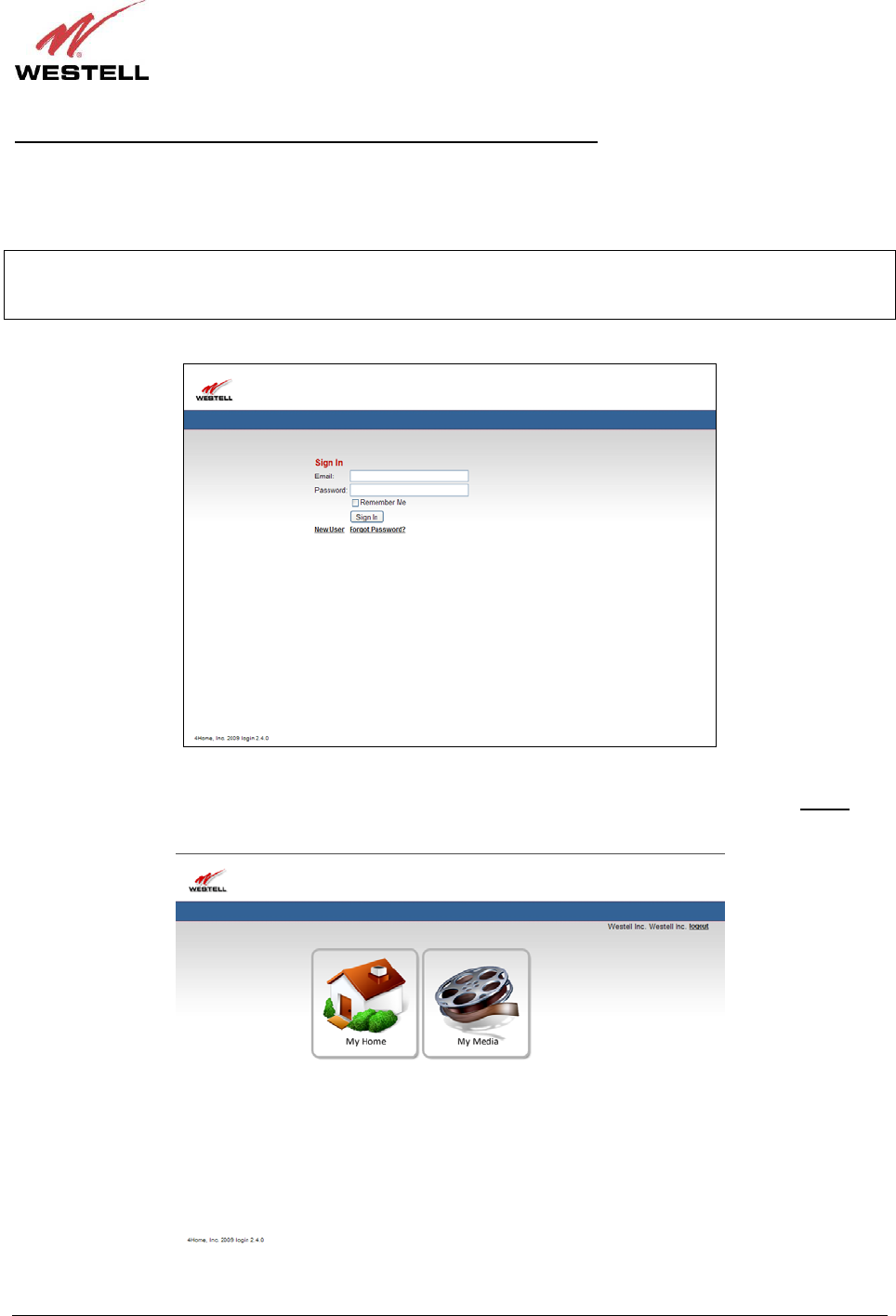
Signing in to Your Account After You Have Completed the Setup Wizard
After you have completed the Setup Wizard and your account has been activated, the following page appears when
you access your Control Point. In this screen, enter your Email and Password, and then click the “Sign In” button to
continue.
IMPORTANT: In order to use this Sign In page, you must first complete the instructions in the Setup Wizard to set
up your account. After you have completed the Setup Wizard, details on accessing your Control Point are explained
later in section 8 of this User Guide.
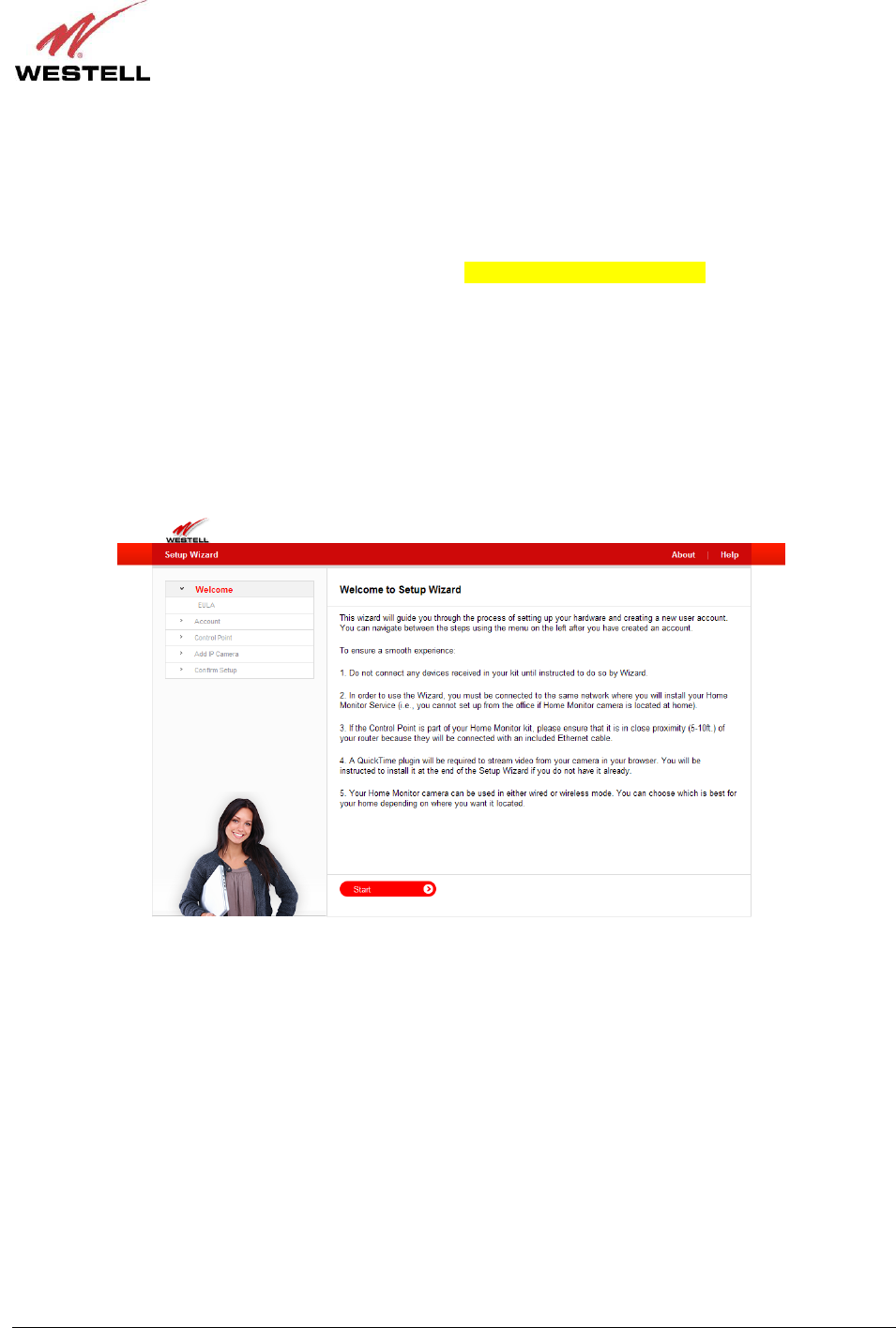
If you clicked “Sign In,” the following page appears. To access the Control Point User Interface, click the My
Home icon. To access your Control Point media services, click the My Media icon. To log out, click the logout link
in the upper-right corner of the screen.
030-300589 Rev. A 16 March 2009
User Guide Control Point Home Monitorin
g
Service
7.2 Starting the Setup Wizard
IMPORTANT: You must run the Setup Wizard from the same network where you will install your Home Monitor
System (that is, you cannot run the Setup Wizard from the office if your Home Monitoring System is installed at
your home).
To start the Setup Wizard, start your browser and then type http://appsdemo.westell.com??? in your browser’s
address bar. Next, press Enter on your keyboard. The following Welcome to Setup Wizard appears.
Please read the following instructions before setting up your account:
• A QuickTime plugin will be required to stream video from your 7521FF Camera to your browser. You will be
instructed to install it at the end of the Setup Wizard—if you do not have QuickTime installed already.
• Your 7521FF Camera can be installed using either an Ethernet cable (wired) or a wireless setup (wirelessly).
You can choose which installation method is best for you depending on where you want to position the Camera.
Please read section 6.3.3 for instructions on installing your Camera.

030-300589 Rev. A 17 March 2009
User Guide Control Point Home Monitorin
g
Service
If you clicked Start in the Welcome to Setup Wizard page, the following page appears. Please read the End User
License Agreement (EULA) and click “Yes, I agree” to continue the Setup Wizard.
NOTE: If you click “No, I do not agree,” you cannot proceed with the Setup Wizard. If desired, you access a
printable version of the EULA, by clicking the Print agreement link in the upper-right corner of the page.
After you click “Yes, I agree,” proceed to section 7.3 for instructions on creating your Control Point account.
030-300589 Rev. A 18 March 2009
User Guide Control Point Home Monitorin
g
Service
7.3 Creating Your Control Point Account
While creating your Control Point account, you will be asked to enter information that will help identify you as a user
as well as enable you to be notified of events and message alerts through your email or mobile phone. The Setup
Wizard will allow you to change your account information anytime before your account is activated—either by
clicking the back button in your Internet browser or by confirming your information in the Account Confirmation
page, displayed later in the setup.
NOTE: If you have questions about your account, please contact your service provider.
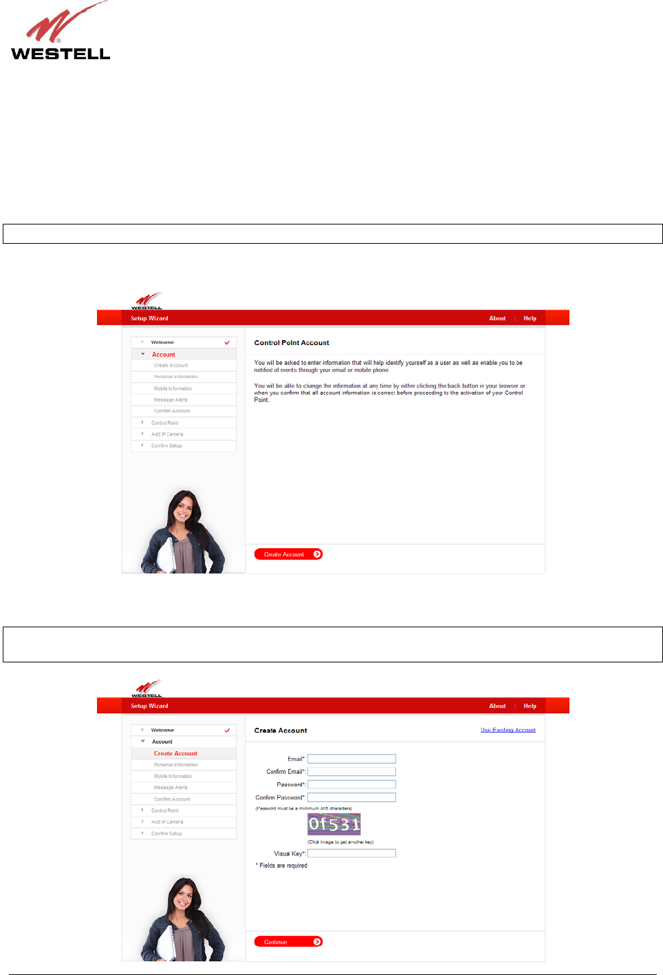
In the following page, click Create Account to continue.
To create a new account, enter the appropriate values in the fields provided, and then click Continue to proceed.
NOTE: An asterisk is displayed next to each field, indicating that you must fill in each field in this page. The
password fields will be masked with dots “●” for security purposes.
030-300589 Rev. A 19 March 2009
User Guide Control Point Home Monitorin
g
Service
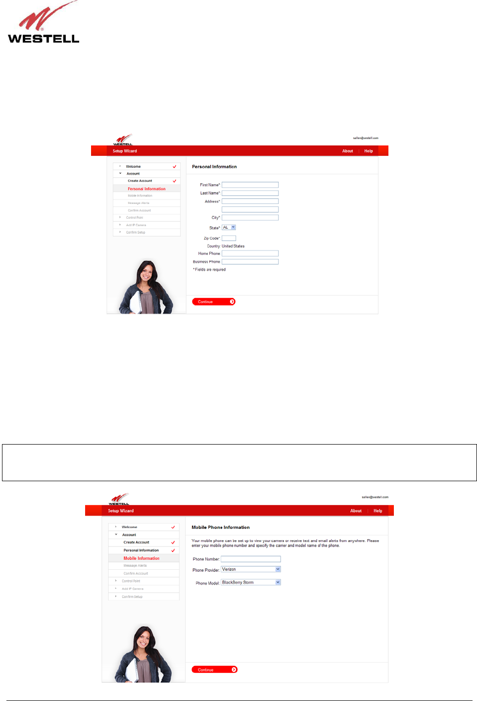
Next, enter your personal information in the following page. If an asterisk “*” is displayed next to a field, this
indicates that you must enter your values into that field. You are not required to fill in a field that does not display an
asterisk next to it.
Enter your information, and then click Continue to proceed.
Control Point supports a variety of mobile phones. Using the following page, you can determine whether your
mobile phone is supported. Simply go to the Phone Model drop-down list and search for the model of your mobile
phone. If your model appears in the list, this means your mobile phone is supported and can be set up to view your
camera from remote locations. Control Point can also send SMS (text) and email message alerts to your mobile
phone. For example, message alerts will be sent to your mobile phone when your Home Monitoring service goes
online or offline, when your camera senses motion, or when media is shared with you by a different user.
To set up your mobile phone for these services, in the following page, enter your mobile phone number, and select
the provider and the model of your phone. Then click Continue to proceed.
IMPORTANT: If you do not enter your mobile phone information into this page, the Control Point User Interface
will not be downloaded onto your mobile phone, and you will not be able to control and monitor your home using
your mobile phone.
030-300589 Rev. A 20 March 2009
User Guide Control Point Home Monitorin
g
Service
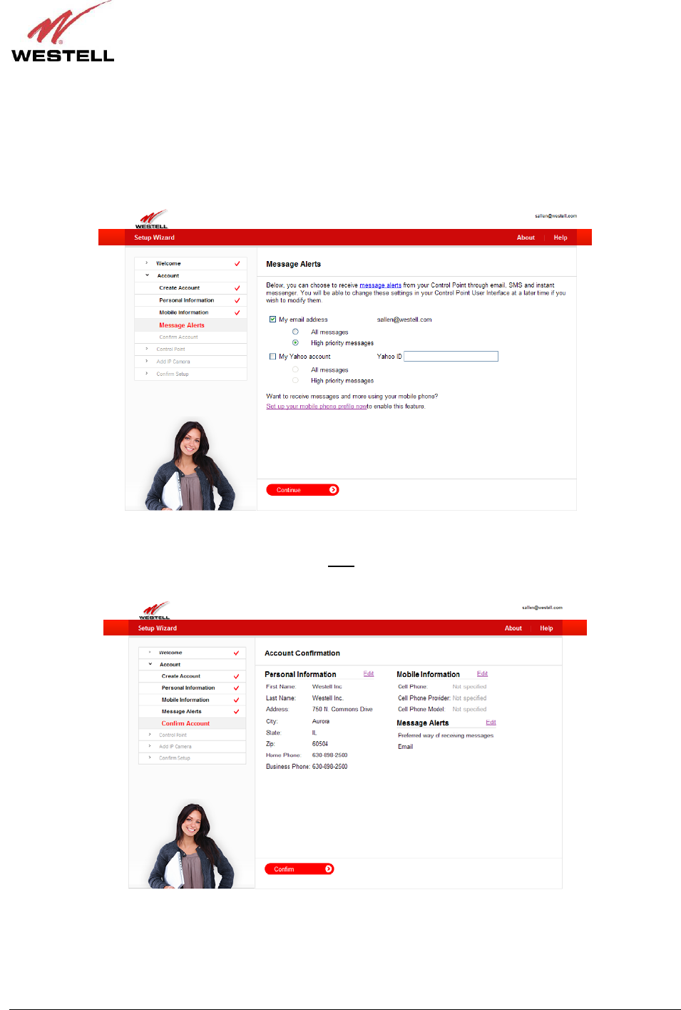
You can choose to receive message alerts from Control Point through email, SMS (text) and instant messenger. The
following page allows you to select the options for receiving message alerts via your Control Point service. If you
want to change these settings at a later time, you can access the settings through your Control Point User Interface,
explained later in section 8 of this User Guide.
In the following page, enter the desired settings, and then click Continue to proceed.
You’re almost finished creating your account. Now you just need to confirm your account information in the
following page. If you want to make changes, click the Edit link next to the information you want to change. After
you confirm your account information, click Confirm to proceed.
Congratulations! You have created your Control Point account successfully. You are now ready to activate your
Control Point. The following section will walk you through the process of activating your Control Point.
030-300589 Rev. A 21 March 2009
User Guide Control Point Home Monitorin
g
Service
7.4 Activating Your Control Point
To begin your Control Point activation, first confirm that the router (to which you have connected the Control Point)
is powered on, connected to the Internet, and functioning properly. If needed, refer section 6, “Installing the
Hardware,” of this User Guide for installation details.
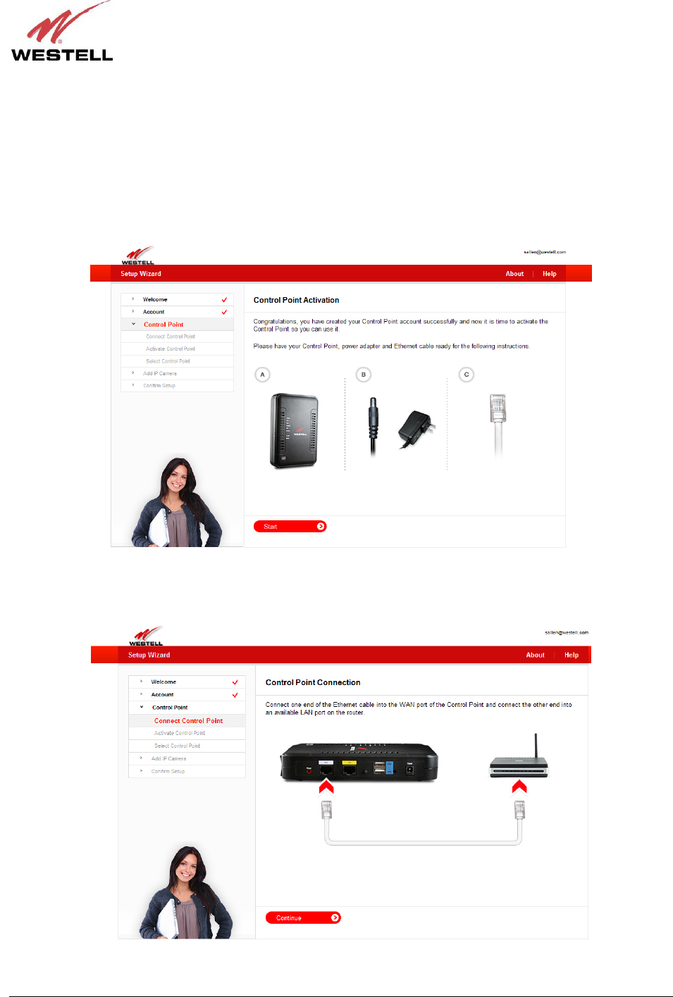
Before starting this section, please have your Control Point, power adapter, and Ethernet cable ready.
Click Start to proceed.
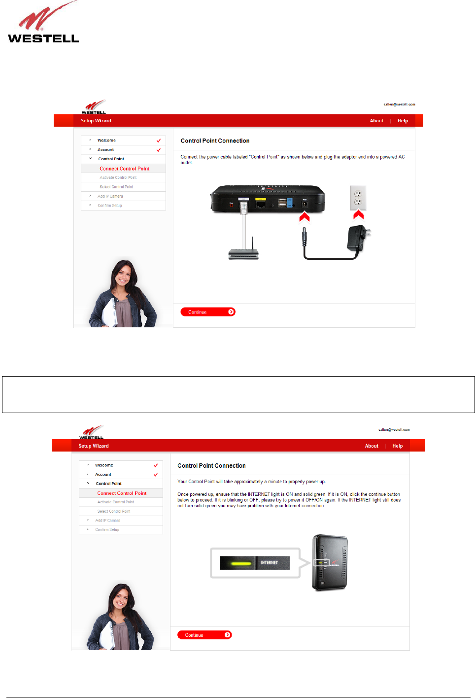
The following page appears. Connect one end of the Ethernet cable into the WAN port of the Control Point, and
then connect the other end of the Ethernet cable into an available LAN port on your gateway or router. Click
Continue to proceed.
030-300589 Rev. A 22 March 2009
User Guide Control Point Home Monitorin
g
Service
Next, connect the small end of the power adapter into power connector on the Control Point, and then plug the other
end into your AC wall outlet. Click Continue to proceed.
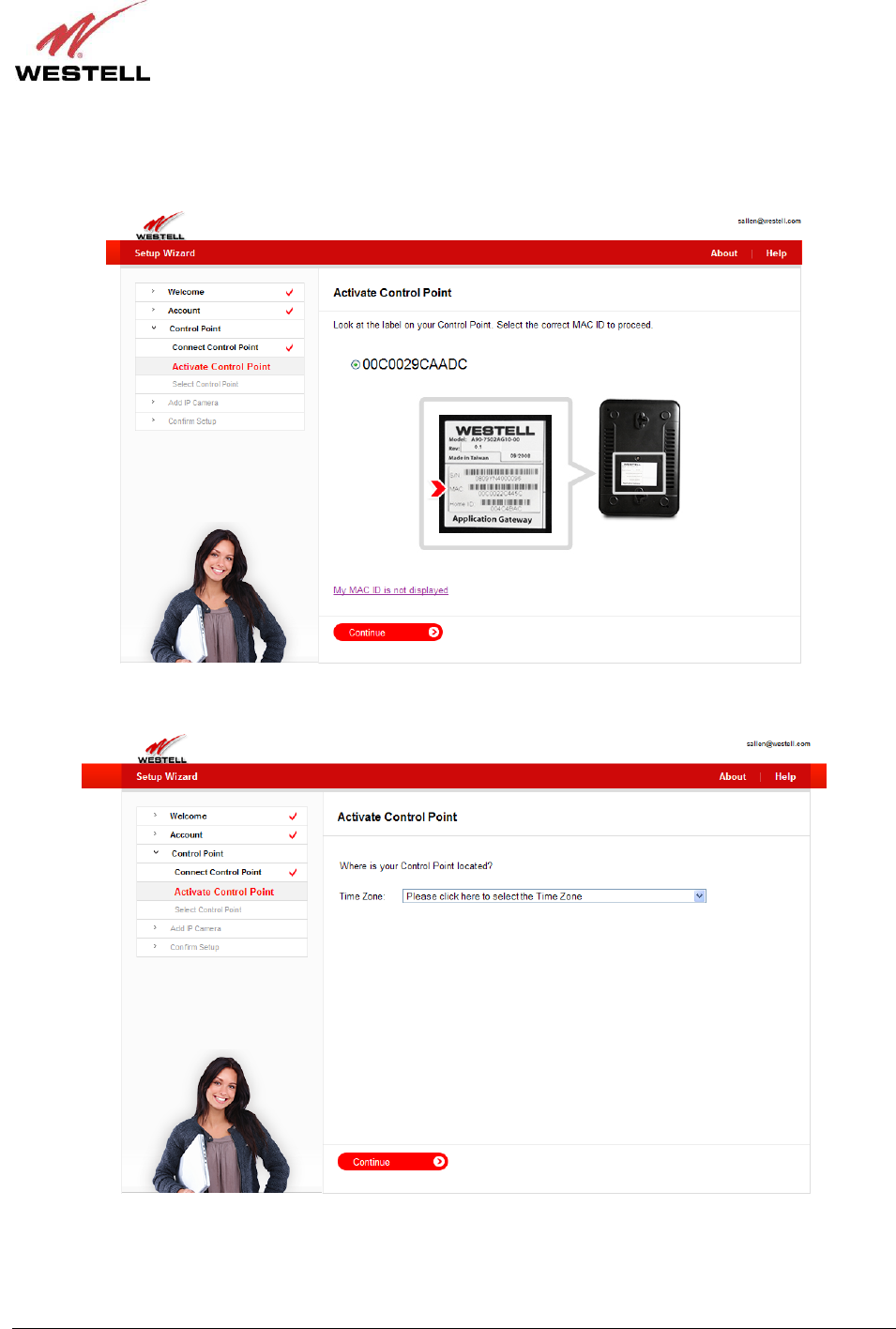
Your Control Point will take approximately a minute to properly power up. Once powered up, check to ensure that
the INTERNET LED is On and solid green. If it is On, click the Continue button in the following page to proceed.
NOTE: If the INTERNET LED is blinking or Off, power the Control Point Off and then On again. If the
INTERNET LED still does not light solid green, you may have a problem with your Internet connection. Please
check your network connections. If problems persist, contact your service provider for further instructions.
030-300589 Rev. A 23 March 2009
User Guide Control Point Home Monitorin
g
Service
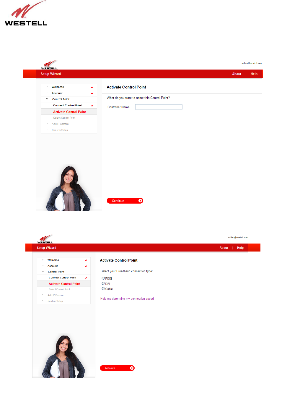
Look at the label located on the bottom of your Control Point. Your Control Point’s MAC ID is displayed in the
label below the MAC bar code. In the following page, click the radio button of the ID that matches your Control
Point’s MAC ID. Click Continue to proceed.
Next, from the Time Zone drop-down list, select the time zone for your area. Click Continue to proceed.
030-300589 Rev. A 24 March 2009
User Guide Control Point Home Monitorin
g
Service
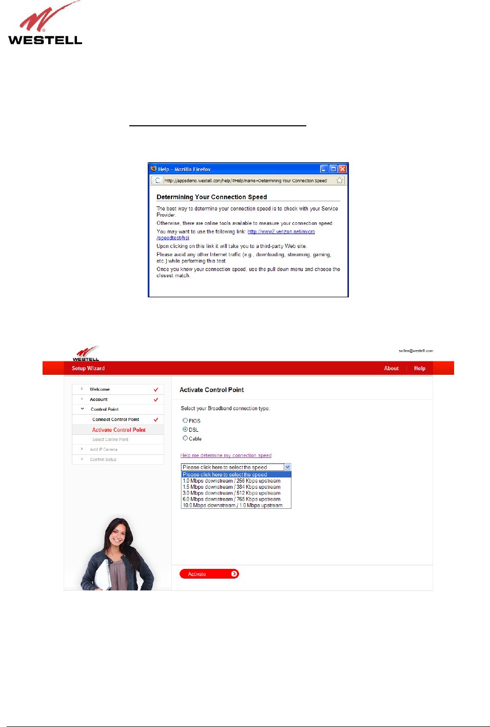
The following page allows you to name your Control Point. Type the desired name in the Controller Name field,
and then click Continue to proceed.
In the following page, click the radio button next to your Broadband connection type.
030-300589 Rev. A 25 March 2009
User Guide Control Point Home Monitorin
g
Service
Your Control Point will request that you select a connection speed. If you are unsure, the best way to determine your
connection speed is to check with your service provider. Also, there are links available on the Internet that can
measure your connection speed.
For example, if you click the Help me determine my connection speed link, following pop-up screen appears.
Clicking the link in the pop-up screen takes you to a third-party Web site that can help determine your connection
speed.
After you have selected your Broadband connection type, go to the drop-down list in the following page and select
the connection speed that is the closest match to your connection speed. Then click Activate to proceed.
030-300589 Rev. A 26 March 2009
User Guide Control Point Home Monitorin
g
Service
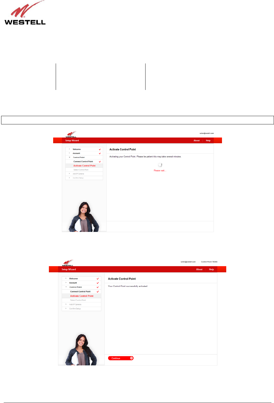
Your Control Point will begin the activation process. While your Control Point is being activated, the Control
Point’s POWER and SERVICE LEDs will display the following behavior:
Control Point LED While Control Point is activating After Control Point has been activated
POWER Solid red Solid green
SERVICE Flashing green Solid green
The page below will appear while your Control Point is being activated.
IMPORTANT: Please wait for the Control Point activation to complete, which may take several minutes.
After your Control Point has been successfully activated, the following page appears. Click Continue to proceed.
030-300589 Rev. A 27 March 2009
User Guide Control Point Home Monitorin
g
Service
7.5 Setting Up Your 7521FF Camera
If you haven’t already assembled your 7521FF Camera, please take a moment to assemble it now. In section 7.5.1,
“Assembling Your Camera,” the Setup Wizard will walk you through these steps. Otherwise, if you have already
assembled your Camera, go to section 7.5.3, “I Have Already Assembled the Camera,” for further instructions.
7.5.1 Assembling Your Camera
IMPORTANT: Please do not power on the Camera or connect any cables to the Camera until instructed to do so.
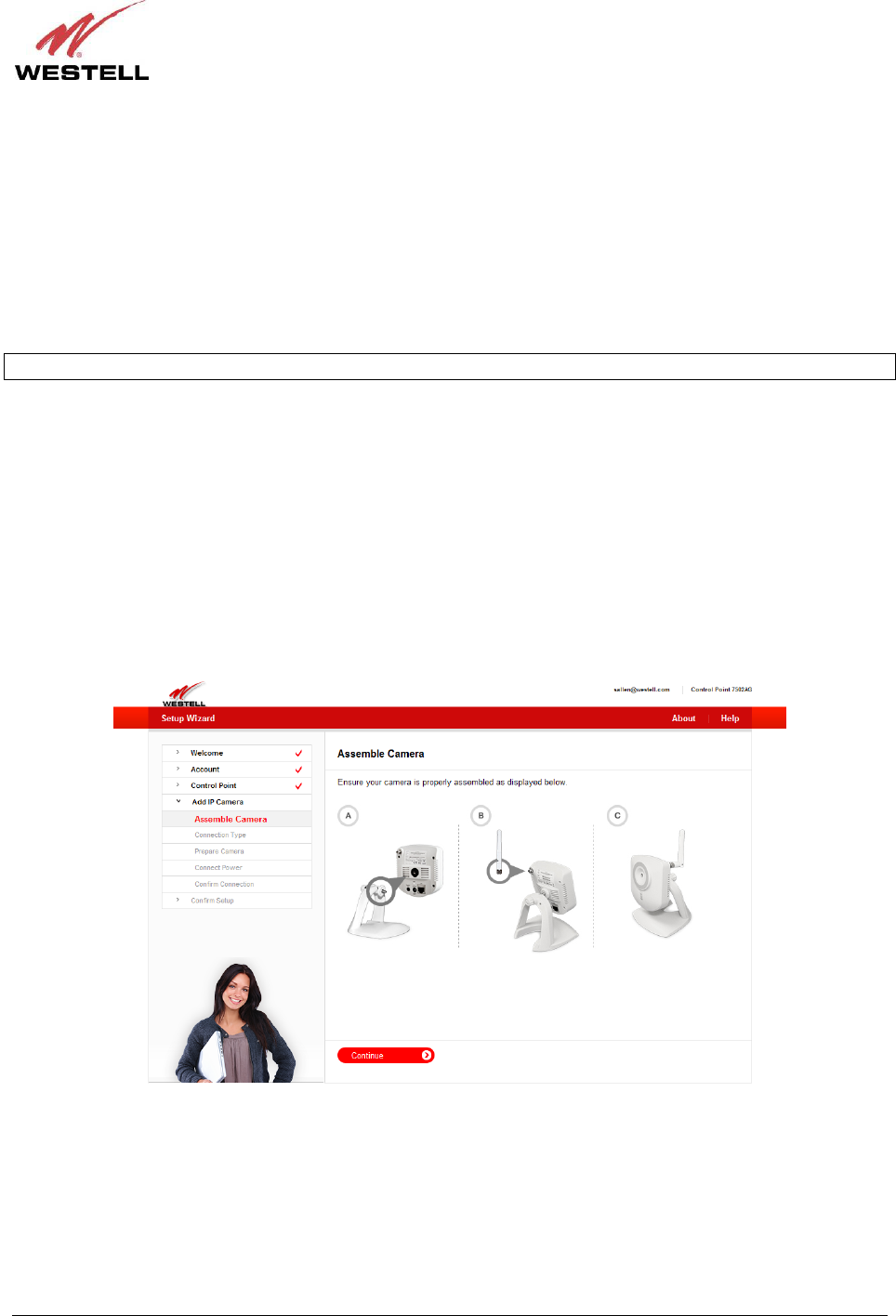
To assembly your 7521FF Camera, please complete these steps. The following illustration is provided to help guide
you through the assembly.
A. Align the threaded hole on the back of the Camera with the screw on the Camera stand, and then turn the
Camera until it is firmly screwed on to the stand.
B. Screw the wireless antenna onto the connector located on the back of the Camera. Make sure the antenna is
firmly locked into place.
C. Orient the antenna to appropriate position.
After you have assembled the Camera, you should be able to tilt the Camera to the desired position. Click Continue
to proceed.
030-300589 Rev. A 28 March 2009
User Guide Control Point Home Monitorin
g
Service
7.5.2 Connecting Your Camera
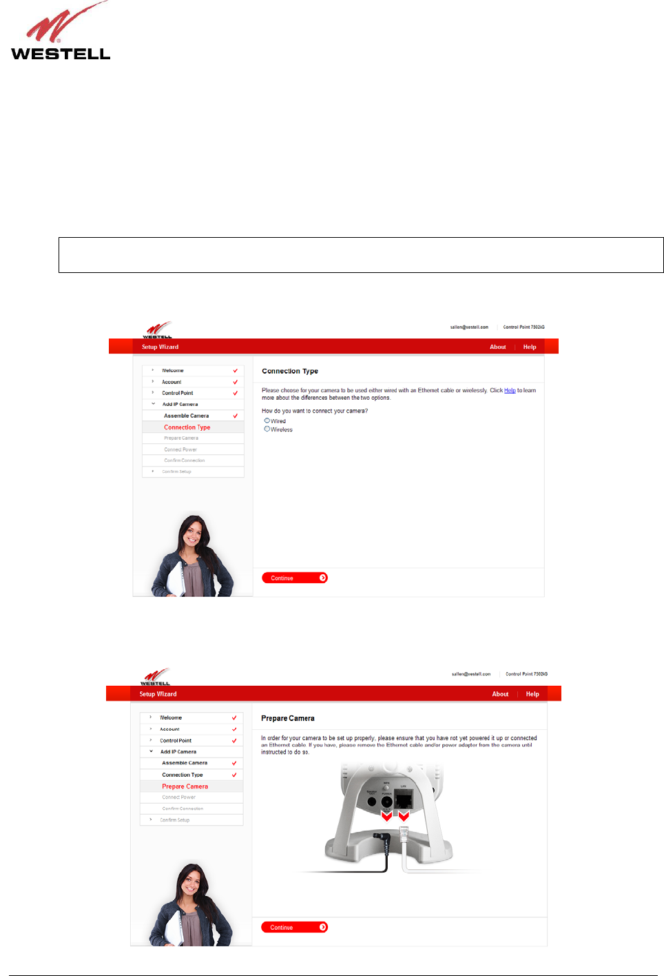
The following page allows you to choose how you want to connect your Camera to your Control Point.
• “Wired” setup means that an Ethernet cable will be plugged in from the router to the Camera at all times.
• “Wireless” setup means that you will be able to relocate your Camera to another part of your home after
you have properly set up your Camera.
NOTE: The typical range for a wireless setup of your Camera is 30-50 ft., and you could have issues
seeing video if the recommended distance between the Camera and the router is exceeded.
Click the radio button of the method you want to use, and then click Continue to proceed.
In order for your Camera to be set up properly, please do not power on the Camera or connect any cables until you
are instructed to do so. Click Continue to proceed.
030-300589 Rev. A 29 March 2009
User Guide Control Point Home Monitorin
g
Service
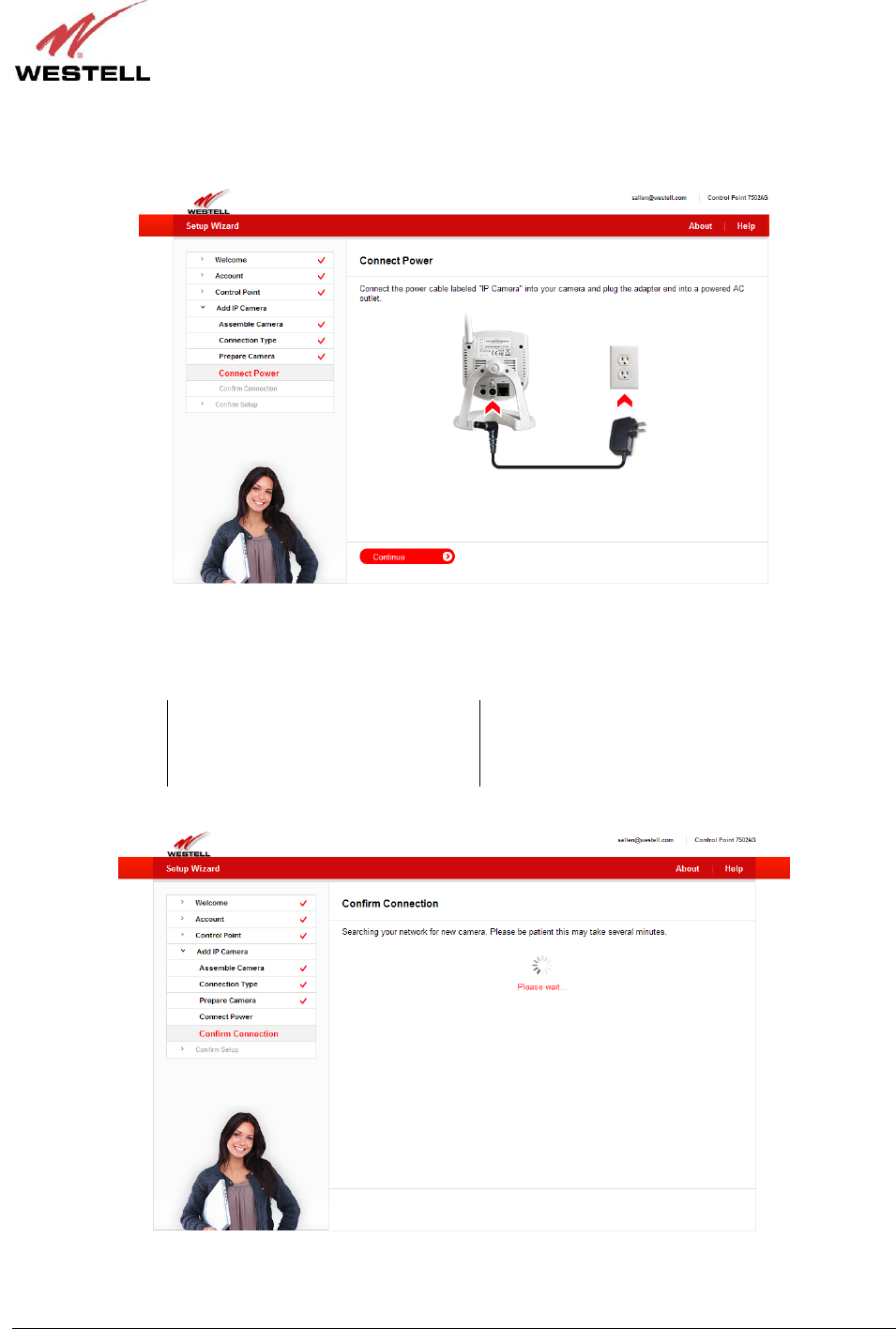
Next, connect the Camera’s power adapter to the Camera and to your AC wall outlet. After you have connected the
power adapter, click Continue to proceed.
Please wait while your Control Point searches the network for your Camera. During the search, the Camera LEDs
will display the following behavior:
Camera LED While Searching for the Camera After the Camera has been detected
Power Flashing green Solid green
Network Flashing green Flashing green (streaming video to the browser)
030-300589 Rev. A 30 March 2009
User Guide Control Point Home Monitorin
g
Service
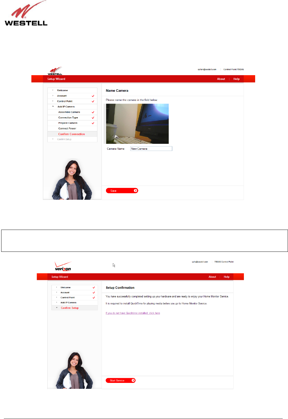
After Control Point has detected your Camera, the following page appears. Type the desired name for your Camera
in the Camera Name field, and then click Save to proceed.
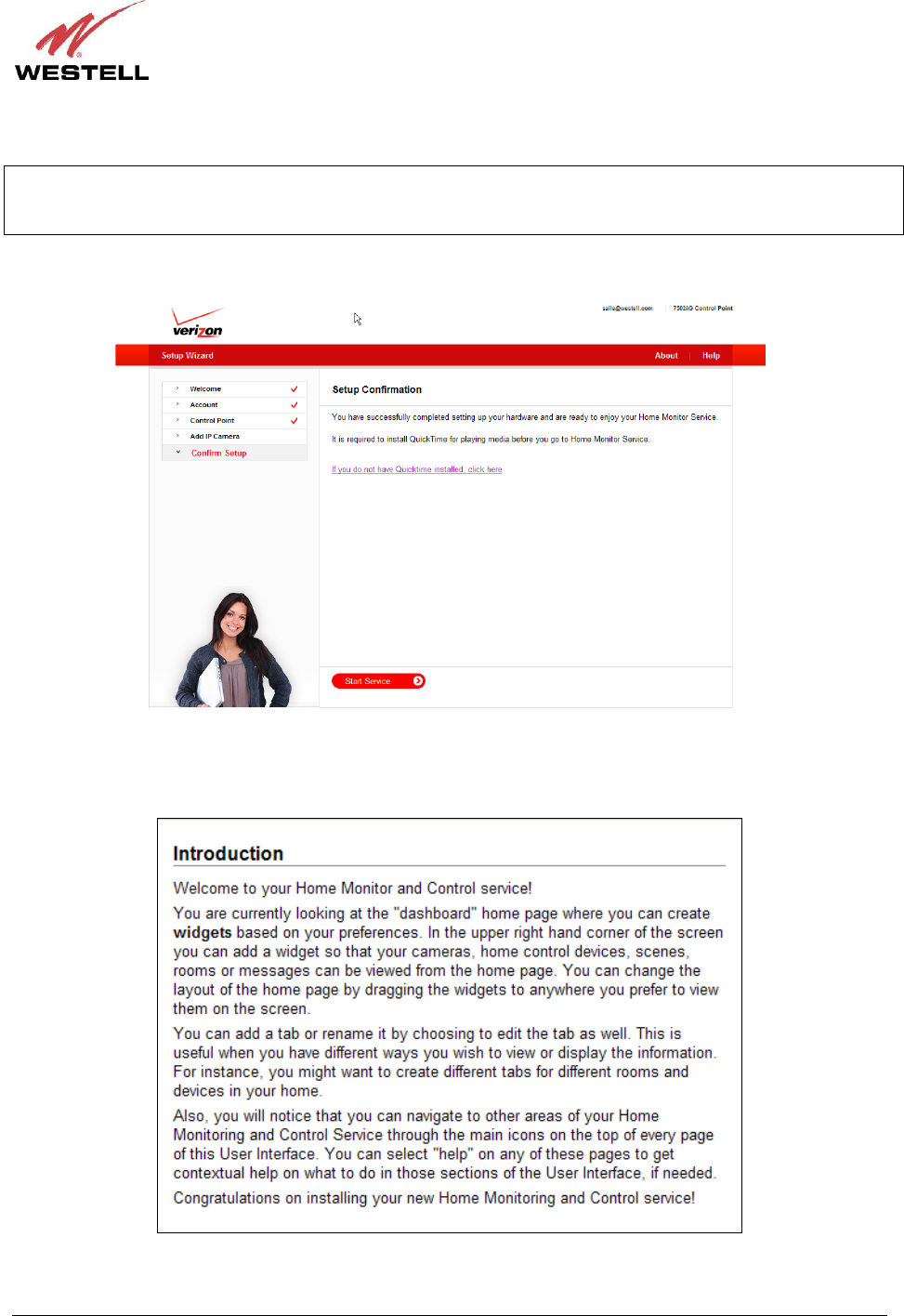
Congratulations! You have successfully completed your Camera setup. Now you are ready to use your Control Point
Home Monitor Service. Click Start Service to proceed.
IMPORTANT: It is required that you have the QuickTime media player installed for before using your Home
Monitor Service. If you don’t have QuickTime installed, click the link in this page to download a copy of QuickTime.
Alternatively, you can download a version of the QuickTime media player from the Internet.
030-300589 Rev. A 31 March 2009
User Guide Control Point Home Monitorin
g
Service
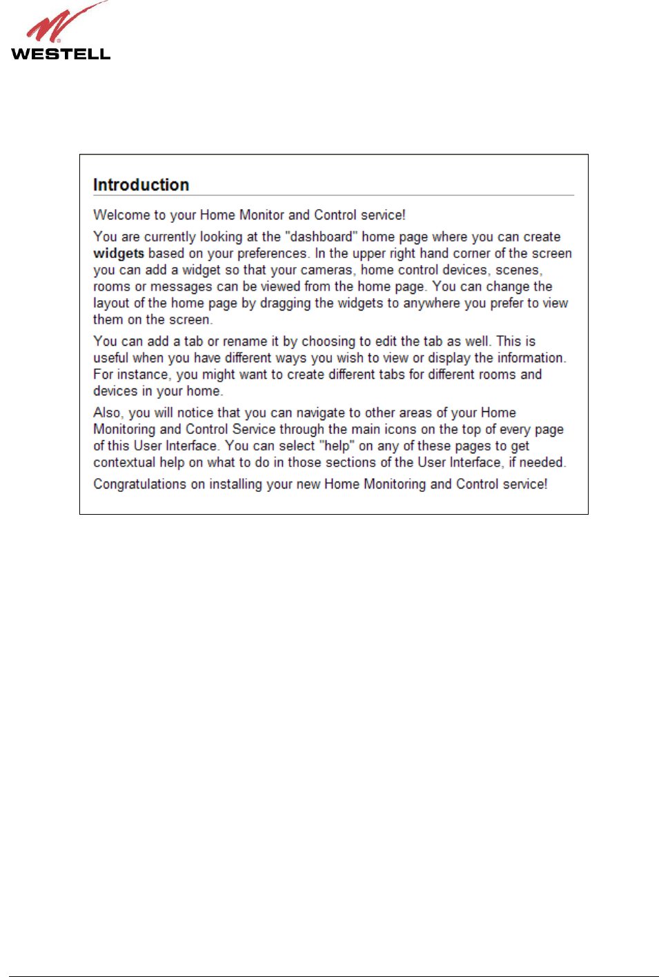
After your Control Point has been successfully activated. The following Introduction briefly appears. Then the
Control Point Home page appears. The Home page will be explained in section 9 of this User Guide. Please proceed
to section 8 for instructions on accessing your Control Point User Interface.
030-300589 Rev. A 32 March 2009
User Guide Control Point Home Monitorin
g
Service
7.5.3 I Have Already Assembled the Camera
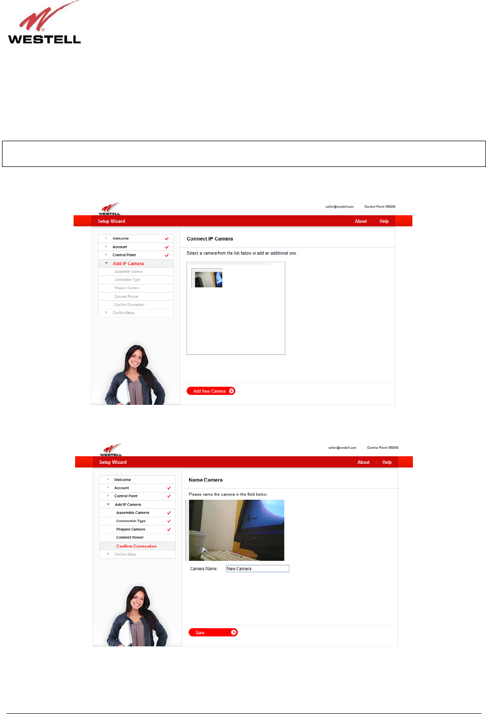
If you have already assembled and installed your Camera as explained earlier in sections 6.3.2 and 6.3.3, the
following page appears after your Control Point has been activated. In this page, select the IP camera you want to
add to your Control Point.
NOTE: You can have more than one IP camera connected to your Control Point. If you have other IP cameras
connected, the page below will display a list of the IP Cameras connected to your Control Point.
Click the image of the IP Camera you want to select, and then click Add New Camera to continue.
Next, type the desired name for your Camera in the Camera Name field, and then click Save to continue.
030-300589 Rev. A 33 March 2009
User Guide Control Point Home Monitorin
g
Service
Congratulations! You have successfully completed your Camera setup.
IMPORTANT: It is required that you have the QuickTime media player installed for before using your Home
Monitor Service. If you don’t have QuickTime installed, click the link in this page to download a copy of QuickTime.
Alternatively, you can download a version of the QuickTime media player from the Internet.
Now you are ready to use your Control Point Home Monitor Service. Click Start Service to proceed.
The following Introduction briefly appears. Then the Control Point Home page appears. The Home page will be
explained in section 9 of this User Guide. Please proceed to section 8 for instructions on accessing your Control
Point User Interface.
User Manual 1

Copyright © 2009 Westell, Inc 030-300589 Rev. A
CONTROL POINT HOME MONITORING SERVICE
USER GUIDE

030-300589 Rev. A 2 March 2009
User Guide Control Point Home Monitorin
g
Service
TABLE OF CONTENTS
1. PRODUCT DESCRIPTION ..................................................................................................................................3
2. SAFETY INSTRUCTIONS ...................................................................................................................................4
3. REGULATORY INFORMATION ........................................................................................................................5
3.1 FCC Compliance Note...............................................................................................................................5
3.2 Canada Certification Notice.......................................................................................................................6
4. MINIMUM REQUIREMENTS .............................................................................................................................7
5. HARDWARE FEATURES....................................................................................................................................8
5.1 LED Indicators...........................................................................................................................................8
5.2 Rear Panel Components.............................................................................................................................9
6. INSTALLING THE HARDWARE......................................................................................................................10
6.1 Installation Requirements ........................................................................................................................10
6.2 Before you begin......................................................................................................................................10
6.3 Installations..............................................................................................................................................11
7. USING THE SETUP WIZARD...........................................................................................................................14
7.1 Before You Begin ....................................................................................................................................14
7.2 Starting the Setup Wizard ........................................................................................................................16
7.3 Creating Your Control Point Account......................................................................................................18
7.4 Activating Your Control Point.................................................................................................................21
7.5 Setting Up Your 7521FF Camera ............................................................................................................27
8. ACCESSING YOUR CONTROL POINT USER INTERFACE .........................................................................34
9. HOME ..................................................................................................................................................................35
9.1 Creating Widgets and Tabs......................................................................................................................36
9.2 Using the Administrator Links.................................................................................................................37
10. CONTROL ...........................................................................................................................................................38
10.1 Devices.....................................................................................................................................................38
10.2 Rooms ......................................................................................................................................................40
10.3 Scenes ......................................................................................................................................................42
10.4 Sensors.....................................................................................................................................................43
10.5 Schedule...................................................................................................................................................45
11. MONITOR ...........................................................................................................................................................47
11.1 Display Panel ...........................................................................................................................................47
11.2 Filmstrip Panel.........................................................................................................................................50
12. TECHNICAL SUPPORT INFORMATION ........................................................................................................51
13. PRODUCT SPECIFICATIONS...........................................................................................................................51
14. SOFTWARE LICENSE AGREEMENT..............................................................................................................52
15. PUBLICATION INFORMATION.......................................................................................................................54

030-300589 Rev. A 3 March 2009
User Guide Control Point Home Monitorin
g
Service
1. PRODUCT DESCRIPTION
The Westell® Control Point Home Monitoring Service is a reliable system that allow you to monitor and control
electronic and wireless devices throughout your home.
This User Guide is intended to provide information on installing and using your Westell® Control Point Home
Monitoring Service and assumes the user of this system has medium to advanced knowledge of networking devices.
To use this product you must have a router or gateway installed and functioning properly on your network along
with active Internet service. Please read all instructions in this User Guide before proceeding with this installation.
The Westell Control Point Home Monitoring devices are powered by ENERGY STAR® qualified adapters.
030-300589 Rev. A 4 March 2009
User Guide Control Point Home Monitorin
g
Service
2. SAFETY INSTRUCTIONS
Please practice general safety precautions when installing any electrical device. Please read and save the following
important safety notes before installing your device:
• Do not use this product near water, for example, near a bathtub, washbowl, kitchen sink or laundry tub, in a
wet basement or near a swimming pool.
• Avoid using a telephone (other than a cordless type) during an electrical storm. There may be a remote risk
of electric shock from lightning.
• Do not use the telephone to report a gas leak in the vicinity of the leak.
• Do not connect this equipment in an environment that is unsuitable.
• Never install any telephone wiring during a lightning storm.
• Never install telephone jacks in wet locations unless the jack is specifically designed for wet locations.
• Never touch non-insulated telephone wires or terminals unless the telephone line has been disconnected at
the network interface.
• Use caution when installing or modifying telephone lines.
WARNING
Risk of electric shock. Voltages up to 140 Vdc (with reference to
ground) may be present on telecommunications circuits.

030-300589 Rev. A 5 March 2009
User Guide Control Point Home Monitorin
g
Service
3. REGULATORY INFORMATION
3.1 FCC Compliance Note
This equipment has been tested and found to comply with the limits for a Class B digital device, pursuant to Part 15
of the Federal Communication Commission (FCC) Rules. These limits are designed to provide reasonable protection
against harmful interference in a residential installation. This equipment generates, uses, and can radiate radio
frequency energy, and if not installed and used in accordance with the instructions, may cause harmful interference
to radio communications. However, there is no guarantee that interference will not occur in a particular installation.
If this equipment does cause harmful interference to radio or television reception, which can be determined by
turning the equipment Off and On, the user is encouraged to try to correct the interference by one or more of the
following measures:
• Reorient or relocate the receiving antenna.
• Increase the separation between the equipment and the receiver.
• Connect the equipment to a different circuit from that to which the receiver is connected.
• Consult the dealer or an experienced radio/TV technician for help.
• This device complies with part 15 of the FCC Rules. Operation is subject to the following two conditions:
(1) this device may not cause harmful interference, and (2) this device must accept any interference
received, including interference that may cause undesired operation.
WARNING: While this device is in operation, a separation distance of at least 20 cm (8 inches) must be maintained
between the radiating antenna and users exposed to the transmitter in order to meet the FCC RF exposure guidelines.
Making changes to the antenna or to the device is not permitted. Doing so may result in the installed system
exceeding RF exposure requirements. This device must not be co-located or operated in conjunction with any other
antenna or radio transmitter. Installers and end users must follow the installation instructions provided in this guide.
Modifications made to the product, unless expressly approved, could void the users’ rights to operate the
equipment.
User Guide Control Point Home Monitorin

030-300589 Rev. A 6 March 2009
Service
3.2 Canada Certification Notice
The Industry Canada label identifies certified equipment. This certification means that the equipment meets certain
telecommunications network protective, operations and safety requirements as prescribed in the appropriate
Terminal Equipment Technical Requirements document(s). The department does not guarantee the equipment will
operate to the user’s satisfaction.
This equipment meets the applicable Industry Canada Terminal Equipment Technical Specification. This is
confirmed by the registration number. The abbreviation, IC, before the registration number signifies that registration
was performed based on a Declaration of Conformity indicating that Industry Canada technical specifications were
met. It does not imply that Industry Canada approved the equipment. The Ringer Equivalence Number (REN) is 0.0.
The Ringer Equivalence Number that is assigned to each piece of terminal equipment provides an indication of the
maximum number of terminals allowed to be connected to a telephone interface. The termination on an interface
may consist of any combination of devices subject only to the requirement that the sum of the Ringer Equivalence
Numbers of all the devices does not exceed five.
Before installing this equipment, users should ensure that it is permissible to be connected to the facilities of the
local Telecommunication Company. The equipment must also be installed using an acceptable method of
connection. The customer should be aware that compliance with the above conditions may not prevent degradation
of service in some situations. Connection to a party line service is subject to state tariffs. Contact the state public
utility commission, public service commission, or corporation commission for information.
If your home has specially wired alarm equipment connected to the telephone line, ensure that the installation of this
equipment (Model 7502AG) does not disable your alarm equipment. If you have questions about what will disable
alarm equipment, consult your telephone company or a qualified installer.
If you experience trouble with this equipment (Model 7502AG), do not try to repair the equipment yourself. The
equipment cannot be repaired in the field and must be returned to the manufacturer. Repairs to certified equipment
should be coordinated by a representative, and designated by the supplier. Contact your service provider for
instructions. The termination on an interface may consist of any combination of devices subject only to the
requirement that the sum of the Ringer Equivalence Numbers of all the devices does not exceed five.
Users should ensure, for their own protection, that the electrical ground connections of the power utility, telephone
lines, and internal, metallic water pipe system, if present, are connected together. This precaution may be
particularly important in rural areas.
CAUTION
Users should not attempt to make such connections themselves, but should contact the
appropriate electrical inspection authority, or electrician, as appropriate.
User Guide Control Point Home Monitorin

030-300589 Rev. A 7 March 2009
User Guide Control Point Home Monitorin
g
Service
4. MINIMUM REQUIREMENTS
To network your 7502AG Control Point, please confirm that you have a gateway or router with an available
10/100 BaseT Ethernet port connected to your network that has active Internet service.
To activate and configure your Control Point services, please confirm that you have the following minimum
computer requirements:
• Pentium® or higher class machines
• Microsoft® Windows® Vista™ or Macintosh® OS X or later
• 64 MB RAM (128 MB recommended)
• 10 MB of free hard drive space
• 10/100 Base-T Network Interface Card (NIC)
• Explorer® 7.0 or later, Firefox® 3.0, or later, Safari® 2.0 or later
To stream video from your 7521FF Camera to your browser, you will need a version (6 or later) of the QuickTime®
media player installed. You will be instructed to install QuickTime® at the end of the Setup Wizard—if you do not
already have it installed.

030-300589 Rev. A 8 March 2009
User Guide Control Point Home Monitorin
g
Service
5. HARDWARE FEATURES
5.1 LED Indicators
LED indicators are located on the front of your 7502AG and 7521FF devices and are used to verify each unit’s
operation and status. This section explains the LED states and descriptions.
7502AG LED States and Descriptions
LED State Description
Solid Green Control Point is powered On.
Solid Red POST (Power On Self Test), Failure (not bootable) or Device
Malfunction. Note: The Control Point Power LED should be red no
longer than two seconds after the power on self test passes.
POWER
Off Control Point is powered Off, or no power is present.
Solid Green USB device detected, LAN activity present (traffic in either direction).
USB link established.
USB1
USB2
Off Control Point is powered Off, No USB device detected, No USB link
established.
Solid Green Ethernet link is established. Transmit or Receive Activity is present on
the Ethernet interface.
ETHERNET
Off Control Point is powered Off, No Ethernet link is established.
Solid Green Wireless link established. Wireless LAN activity is present (traffic in
either direction).
Flashing Green Wireless link is being established.
WIFI
Off Control Point is powered Off, or No Link established
Solid Green
Internet link established. The Control Point has a WAN IP address
from IPCP or DHCP; or a static IP is configured.
IP connection established and IP Traffic is passing through device (in
either direction.
INTERNET
Off No Internet link established.
Solid Green Control Point has detected a Z-Wave device, Connection is established,
via wired or wirelessly.
Z-Wave Off Control Point is powered Off, Control Point has not detected a Z-Wave
device on the network (via wired or wireless connection).
Solid Green Control Point has been Activated. Connection established with Control
Point’s portal server, Control Point is passing traffic to the portal
server.
Flashing Green Control Point is in Activation Mode.
SERVICE
Off Control Point is powered Off, No connection established with the
portal server.
7521FF IP Camera LED States and Descriptions
LED State Description
Solid Green Camera is powered On.
Flashing Green Camera is in power on mode.
Power
Off Camera is powered Off, or no power is present.
Solid Green Camera has established a connection with the Control Point.
Flashing Green Camera is connecting to Control Point, or Camera is send data.
Network
Off Camera is powered Off, or no network connection established.
030-300589 Rev. A 9 March 2009
User Guide Control Point Home Monitorin
g
Service
5.2 Rear Panel Components
• Reset button
• 10/100 Base-T Ethernet connector (WAN)
• 10/100 Base T Ethernet connector (LAN))
• Z-Wave push button
• USB connectors (USB1/USB2)
• Power connector
7502AG – Rear Panel
The following table describes the 7502AG Control Point rear panel components.
NAME TYPE FUNCTION
Reset
Recessed push
button
Allows you to reboot the 7502AG or to restore the 7502AG to factory default
configuration settings. If pressed for less than 5 seconds, the device will reboot.
If pressed more than 10 seconds, the device will be restored to factory default
settings.
WAN 8-pin (RJ-45)
modular jack
Connects the 7502AG to a gateway on your existing network, enabling access
to Control Point services via the Internet or Wide Area Network (WAN).
LAN 8-pin (RJ-45)
modular jack Connects the 7502AG to another Ethenet-enabled device on your LAN.
Z-Wave Push button
Z-Wave button allows you to add Z-Wave-complient devices to your Control
Point.
USB1/USB2 USB connector
Connects USB storage devices such as memory sticks to the 7502AG, enabling
external, local storage.
12 VDC Barrel power
connector
12 VDC power adapter connects the 7502AG to your wall outlet or to a power
strip. Use only the power adapter provided with your kit.
Ethernet
Connector
(WAN)
Power
Connector
USB
Connectors
Z-Wave
Button
Reset
Button
Ethernet
Connector
(LAN)

030-300589 Rev. A 10 March 2009
User Guide Control Point Home Monitorin
g
Service
6. INSTALLING THE HARDWARE
This section explains the hardware installation procedures for connecting your 7502AG Control Point to your
network.
6.1 Installation Requirements
To install the 7502AG, you will need the following:
• Available Ethernet port on the gateway or router to which you will connect the 7502AG
• Active Internet service for setting up and activating your Control Point service
6.2 Before you begin
Make sure that your kit contains the following items:
• 7502AG Control Point
• 7521FF IP Camera
• Camera
• Wireless antenna
• Camera stand
• Two 10/100 Base-T Ethernet cables
• 12 VDC Power Adapter for powering the 7502AG Control Point
• 5 VDC Power Adapter for powering the 7521FF Camera
• Westell CD-ROM containing Quick Time and
User Guide in PDF format (requires Adobe® Reader installed)

030-300589 Rev. A 11 March 2009
User Guide Control Point Home Monitorin
g
Service
6.3 Installations
The following instructions explain how to connect the 7502AG Control Point to your existing network. Before you
begin, please read the following notes:
IMPORTANT:
1. Make sure the gateway or router on your existing network is powered on a functioning properly.
2. Westell recommends the use of a surge suppressor to protect electronic devices attached to your network.
Please use only the power adapter provided with your kit.
6.3.1 Connecting Your 7502AG Control Point to Your Gateway
To connect your 7502AG to your gateway, please follow these steps:
1. Plug one end of the Ethernet cable into the jack labeled WAN on the back of the 7502AG. Plug the other end of
the Ethernet cable into the Ethernet jack on your gateway.
2. To connect an Ethernet device to your 7502AG, get the other Ethernet cable and connect it from the Ethernet
device to the Ethernet jack labeled LAN on the back of the 7502AG.
3. Plug the small end of the 7502AG power supply cord into the power connector marked 12 VDC on the back of the
7502AG. Plug the other end of the power supply into an AC wall socket or a power strip.
4. Check to see if the POWER LED on the 7502AG is solid green. If the POWER LED is solid green, the
7502AG is functioning properly.
5. Check to see if the ETHERNET LED on the 7502AG is solid green. Solid green indicates that an Ethernet
connection is established.
6. Check to see if the INTERNET LED on the 7502AG is solid green. Solid green indicates that the 7502AG is
successfully joined to your network.
6.3.2 Assembling Your 7521FF Camera
To assembly your 7521FF Camera, please follow these steps:
1. Align the threaded hole on the back of the Camera with the screw on the Camera stand, and then turn the
Camera until it is firmly screwed on to the stand.
2. Screw the wireless antenna onto the connector located on the back of the Camera. Make sure the antenna is
firmly locked into place.
3. Orient the antenna to appropriate position.
After you have assembled the Camera, you should be able to tilt the Camera to the desired position.

030-300589 Rev. A 12 March 2009
User Guide Control Point Home Monitorin
g
Service
6.3.3 Connecting Your 7521FF Camera to the 7502AG Control Point
Your 7521FF Camera can be installed to your 7502AG either using a “wired” setup or using a “wireless” setup. A
wired setup means that an Ethernet cable will be plugged in from the router to the Camera at all times. A “wireless”
setup means that you will be able to relocate your Camera to another part of your home.
NOTE: The typical range for a wireless setup of your Camera is 30-50 ft., and you could have issues seeing video if
the recommended distance between the Camera and the router is exceeded.
You can choose the installation method you want to use depending on where you want to position the camera. The
following sections describe each method.
6.3.3.1 Installing the 7521FF Camera via Wireless Setup
Your Control Point supports different methods for setting up a wireless connection between your 7521FF Camera and
your 7502AG. One method is to use the Setup Wizard, explained later in this User Guide. Another method is to use
the WPS button on the devices to establish a wireless connection.
During the developmental period for an easy push-button method for securely connecting wireless devices,
manufacturers were eager to deliver their own push-button methods, and the common name used was “Simple
Config.” When the procedure finally became standardized, it was renamed to Wi-Fi Protected Setup or WPS, by the
standards organization.
WPS simplifies establishing wireless connections between wireless devices and your 7502AG Router. Although
some devices do not support WPS, for those that do, you can use WPS to quickly connect to your 7502AG without
first having to input long security keywords. Your 7521FF supports WPS and will automatically acquire the security
settings of your 7502AG and establish a wireless link.
If you want to use WPS, you must follow the instructions in this section, and then skip the Camera setup instructions
in the Setup Wizard, explained in section 7.5 of this User Guide.
To install the 7521FF Camera using WPS, please follow these steps:
1. Position the Camera so that it is located within three feet of the 7502AG.
2. Plug the small end of the 7521FF power supply cord into the power connector marked Power/5V on the back of
the 7521FF Camera. Plug the other end of the power supply into an AC wall socket or a power strip.
3. Check to see if the Power LED on the front of the 7521FF Camera is solid green. Solid green indicates the
Camera is powered on.
4. Press the WPS button on the top of the 7502AG for approximately three seconds. Wait five seconds, and then
press the WPS button on the back of the 7521FF Camera for approximately three seconds. Then, wait a moment
for the 7521FF Camera to establish a wireless link to the 7502AG. While the connection is being established, the
WIFI LED on the 7502AG will be flashing green, and the Network LED on the 7521FF will be flashing green.
5. Once the Camera has established a wireless link to the 7502AG, check the WIFI LED on the 7502AG—it should
be solid green, indicating that a link is established.
6. Check the Network LED on the 7521FF Camera—it will be flashing green, indicating that the Camera functioning
properly.
If you remove power from the Camera, you do not need to repeat these steps when you power it on again, you can
simply power on the Camera and wait for the Camera to establish a wireless link to the 7502AG.

030-300589 Rev. A 13 March 2009
User Guide Control Point Home Monitorin
g
Service
6.3.3.2 Installing the 7521FF Camera via Ethernet Cable
To install the 7521FF Camera via an Ethernet cable, please follow these steps:
1. Plug one end of an Ethernet cable into the jack labeled LAN on the back of the 7502AG. Plug the other end of
the Ethernet cable into the Ethernet jack labeled LAN on the back of your 7521FF Camera.
2. Plug the small end of the 7521FF power supply cord into the power connector marked Power/5V on the back of
the 7521FF. Plug the other end of the 7521FF power supply into an AC wall socket or a power strip.
3. Check to see if the Power LED on the front of the 7521FF Camera is solid green. Solid green indicates the
Camera is functioning properly.
4. Check to see if the Ethernet LED on the 7502AG is solid green. Solid green indicates that an Ethernet
connection is established.
6.3.4 Connecting a Z-Wave Adapter to Your 7502AG Control Point
This section describes how to connect a Z-Wave adapter to your 7502AG.
Z-Wave® is a wireless communications standard designed for home automation, specifically to remote control
applications in residential and light commercial environments. The technology has been standardized by the Z-Wave
Alliance, an international consortium of manufacturers that oversees interoperability between Z-Wave products and
enabled devices. Using a Z-Wave adapter allows you to control home electronic devices such as a lighting,
appliances, entertainment systems, or any device in your home that runs on electricity. Once you have installed your
Z-Wave adapter, attached a device, and setup your Control Point service, you can access your service from your
home, office, mobile phone, or wherever you have Internet access, allowing you to control the device locally or
remotely though your Control Point User Interface.
NOTE: Z-Wave adapters are not included with your kit; however, they can be purchased from computer hardware
retailers.
For example, you can connect your Z-Wave adapter to your 7502AG as explained in the following steps. Then plug
a device—a lamp for example—into your Z-Wave adapter. The Z-Wave adapter will connect to your 7502AG
wirelessly. This setup enables you to power on and power off your lamp both at home and away from home using
your Control Point service. Details on setting up your Control Point service will be explained later in this User
Guide.
IMPORTANT: After you plug a device into your Z-Wave adapter, make sure the device remains powered on so
that you can control the device using your Control Point service.
To install the Z-Wave adapter and connect to the 7502AG, please follow these steps:
1. Plug the Z-Wave adapter into an AC wall socket or a power strip.
2. Press the Z-Wave button on the back of the 7502AG to allow the Z-Wave adapter to connect wirelessly to the
7502AG.
3. Check to see if the LED on the Z-Wave adapter is solid green. Solid green indicates that the adapter is
functioning properly.
4. Check to see if the Z-Wave LED on the 7502AG is solid green. Solid green means the Z-Wave adapter has
connected to your 7502AG.

030-300589 Rev. A 14 March 2009
User Guide Control Point Home Monitorin
g
Service
7. USING THE SETUP WIZARD
Welcome to the Home Monitor service Setup Wizard!
To use your 7502AG Control Point Home Monitoring Service, you must first set up your account profile and then
activate your Control Point service. Your 7502AG provides a Setup Wizard to guide you through this process.
Follow the instructions in the Setup Wizard to quickly set up your Control Point service.
IMPORTANT: The Setup Wizard requires that you have Internet connectivity at all times in order to save
information in the Wizard.
7.1 Before You Begin
Before you begin the Setup Wizard, please ensure that the products in your kit are unpacked and available because
the Setup Wizard will instruct to connect them. Also, please make sure you have obtained the following information
because the Setup Wizard will request that you enter this information later in the setup.
• Connection Speed: The speed at which your gateway is connecting to the Internet, provided by you ISP.
• Email Address: Your email address you will use for receiving message alerts from Control Point.
• Broadband Connection Type: The broadband type that allows you to have Internet access, for example
FiOS, DSL, or Cable.
• Mobile Phone Number: Optional, If desired you can allow your mobile phone to receive message alerts
from Control Point.
After completing the Setup Wizard, you will have done the following:
• Created your personal account
• Configured Mobile and Messaging preferences
• Activated your Control Point service
• Detected and installed your 7521FF IP Camera
• Been redirected to your Home Monitoring User Interface
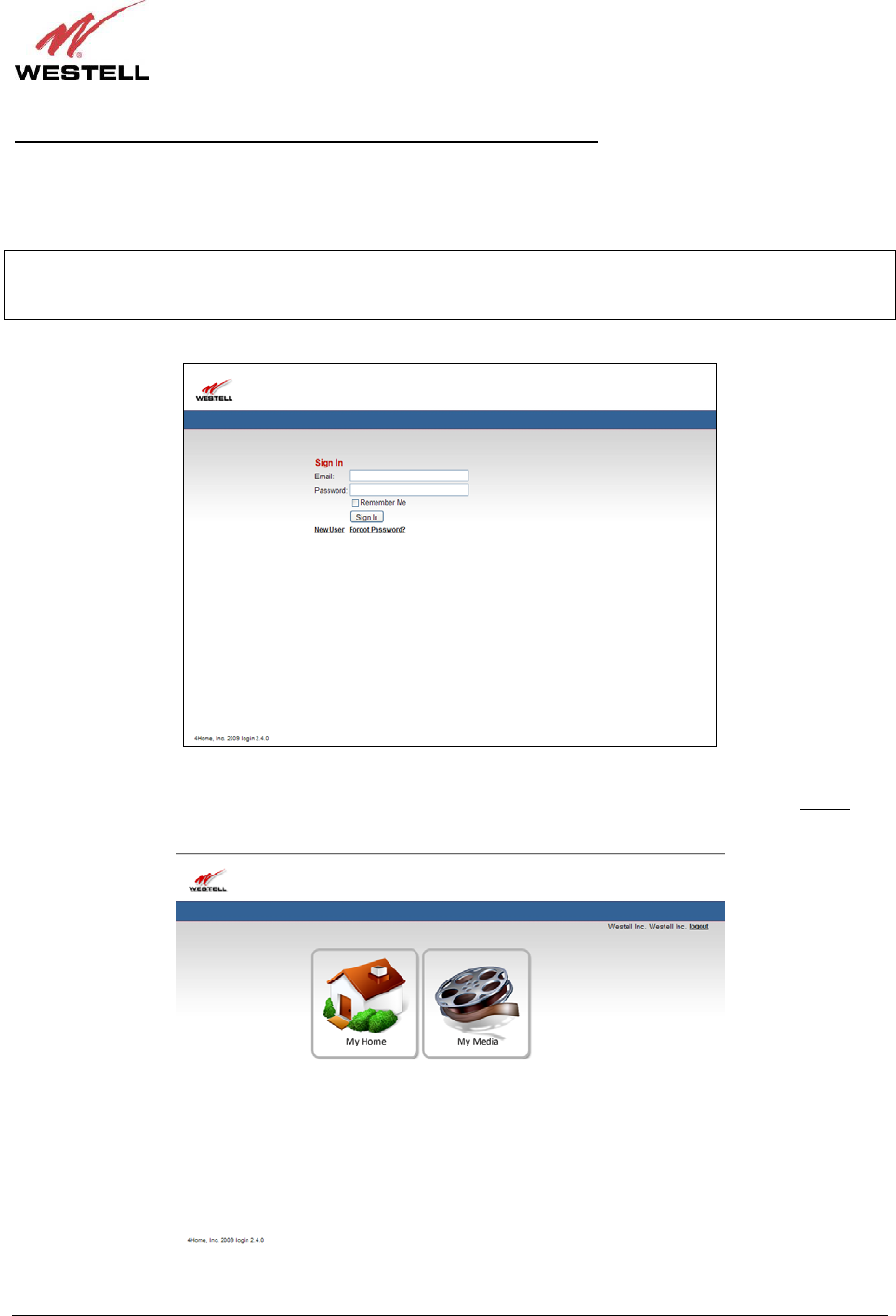
030-300589 Rev. A 15 March 2009
User Guide Control Point Home Monitorin
g
Service
Signing in to Your Account After You Have Completed the Setup Wizard
After you have completed the Setup Wizard and your account has been activated, the following page appears when
you access your Control Point. In this screen, enter your Email and Password, and then click the “Sign In” button to
continue.
IMPORTANT: In order to use this Sign In page, you must first complete the instructions in the Setup Wizard to set
up your account. After you have completed the Setup Wizard, details on accessing your Control Point are explained
later in section 8 of this User Guide.
If you clicked “Sign In,” the following page appears. To access the Control Point User Interface, click the My
Home icon. To access your Control Point media services, click the My Media icon. To log out, click the logout link
in the upper-right corner of the screen.
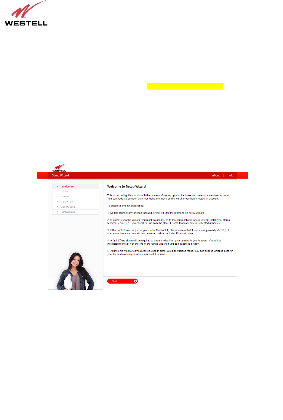
030-300589 Rev. A 16 March 2009
User Guide Control Point Home Monitorin
g
Service
7.2 Starting the Setup Wizard
IMPORTANT: You must run the Setup Wizard from the same network where you will install your Home Monitor
System (that is, you cannot run the Setup Wizard from the office if your Home Monitoring System is installed at
your home).
To start the Setup Wizard, start your browser and then type http://appsdemo.westell.com??? in your browser’s
address bar. Next, press Enter on your keyboard. The following Welcome to Setup Wizard appears.
Please read the following instructions before setting up your account:
• A QuickTime plugin will be required to stream video from your 7521FF Camera to your browser. You will be
instructed to install it at the end of the Setup Wizard—if you do not have QuickTime installed already.
• Your 7521FF Camera can be installed using either an Ethernet cable (wired) or a wireless setup (wirelessly).
You can choose which installation method is best for you depending on where you want to position the Camera.
Please read section 6.3.3 for instructions on installing your Camera.

030-300589 Rev. A 17 March 2009
User Guide Control Point Home Monitorin
g
Service
If you clicked Start in the Welcome to Setup Wizard page, the following page appears. Please read the End User
License Agreement (EULA) and click “Yes, I agree” to continue the Setup Wizard.
NOTE: If you click “No, I do not agree,” you cannot proceed with the Setup Wizard. If desired, you access a
printable version of the EULA, by clicking the Print agreement link in the upper-right corner of the page.
After you click “Yes, I agree,” proceed to section 7.3 for instructions on creating your Control Point account.
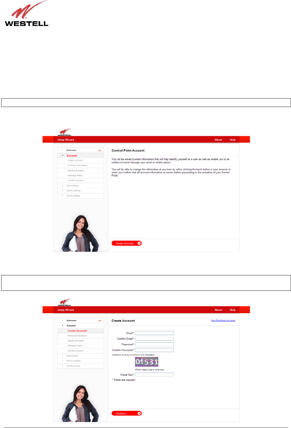
030-300589 Rev. A 18 March 2009
User Guide Control Point Home Monitorin
g
Service
7.3 Creating Your Control Point Account
While creating your Control Point account, you will be asked to enter information that will help identify you as a user
as well as enable you to be notified of events and message alerts through your email or mobile phone. The Setup
Wizard will allow you to change your account information anytime before your account is activated—either by
clicking the back button in your Internet browser or by confirming your information in the Account Confirmation
page, displayed later in the setup.
NOTE: If you have questions about your account, please contact your service provider.
In the following page, click Create Account to continue.
To create a new account, enter the appropriate values in the fields provided, and then click Continue to proceed.
NOTE: An asterisk is displayed next to each field, indicating that you must fill in each field in this page. The
password fields will be masked with dots “●” for security purposes.
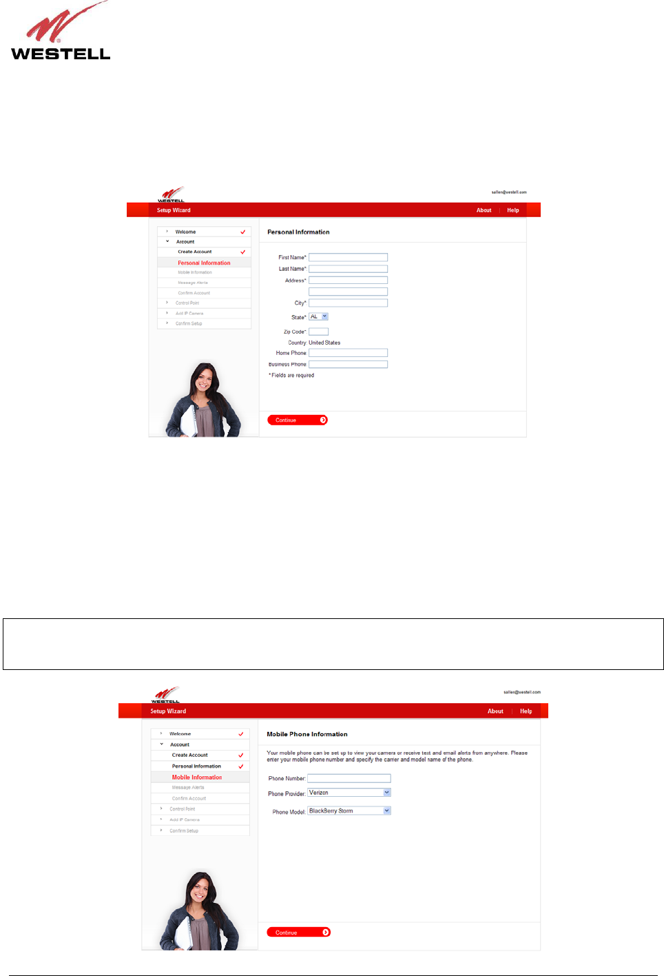
030-300589 Rev. A 19 March 2009
User Guide Control Point Home Monitorin
g
Service
Next, enter your personal information in the following page. If an asterisk “*” is displayed next to a field, this
indicates that you must enter your values into that field. You are not required to fill in a field that does not display an
asterisk next to it.
Enter your information, and then click Continue to proceed.
Control Point supports a variety of mobile phones. Using the following page, you can determine whether your
mobile phone is supported. Simply go to the Phone Model drop-down list and search for the model of your mobile
phone. If your model appears in the list, this means your mobile phone is supported and can be set up to view your
camera from remote locations. Control Point can also send SMS (text) and email message alerts to your mobile
phone. For example, message alerts will be sent to your mobile phone when your Home Monitoring service goes
online or offline, when your camera senses motion, or when media is shared with you by a different user.
To set up your mobile phone for these services, in the following page, enter your mobile phone number, and select
the provider and the model of your phone. Then click Continue to proceed.
IMPORTANT: If you do not enter your mobile phone information into this page, the Control Point User Interface
will not be downloaded onto your mobile phone, and you will not be able to control and monitor your home using
your mobile phone.
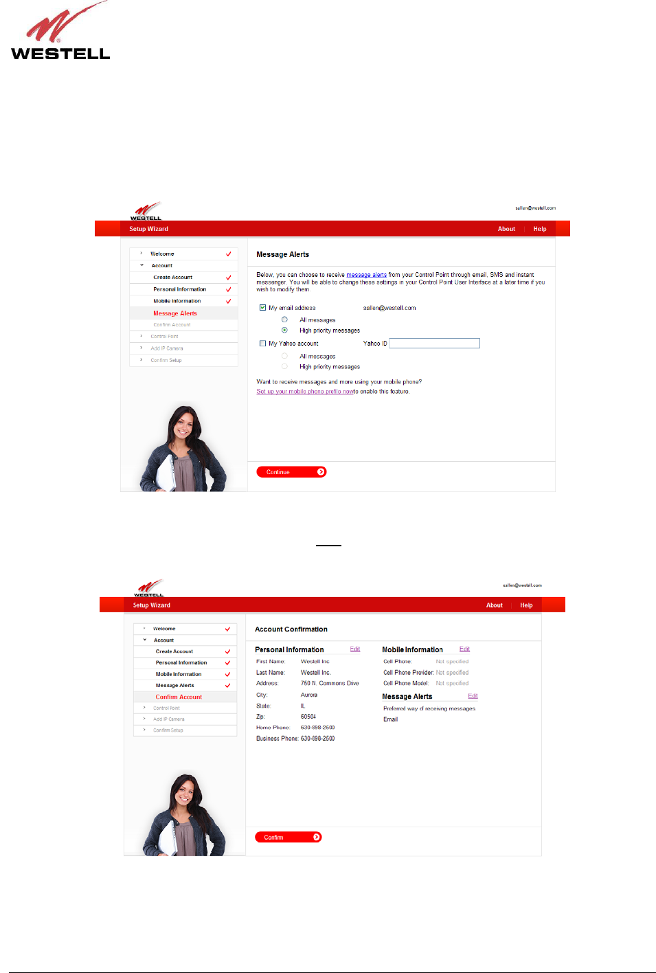
030-300589 Rev. A 20 March 2009
User Guide Control Point Home Monitorin
g
Service
You can choose to receive message alerts from Control Point through email, SMS (text) and instant messenger. The
following page allows you to select the options for receiving message alerts via your Control Point service. If you
want to change these settings at a later time, you can access the settings through your Control Point User Interface,
explained later in section 8 of this User Guide.
In the following page, enter the desired settings, and then click Continue to proceed.
You’re almost finished creating your account. Now you just need to confirm your account information in the
following page. If you want to make changes, click the Edit link next to the information you want to change. After
you confirm your account information, click Confirm to proceed.
Congratulations! You have created your Control Point account successfully. You are now ready to activate your
Control Point. The following section will walk you through the process of activating your Control Point.
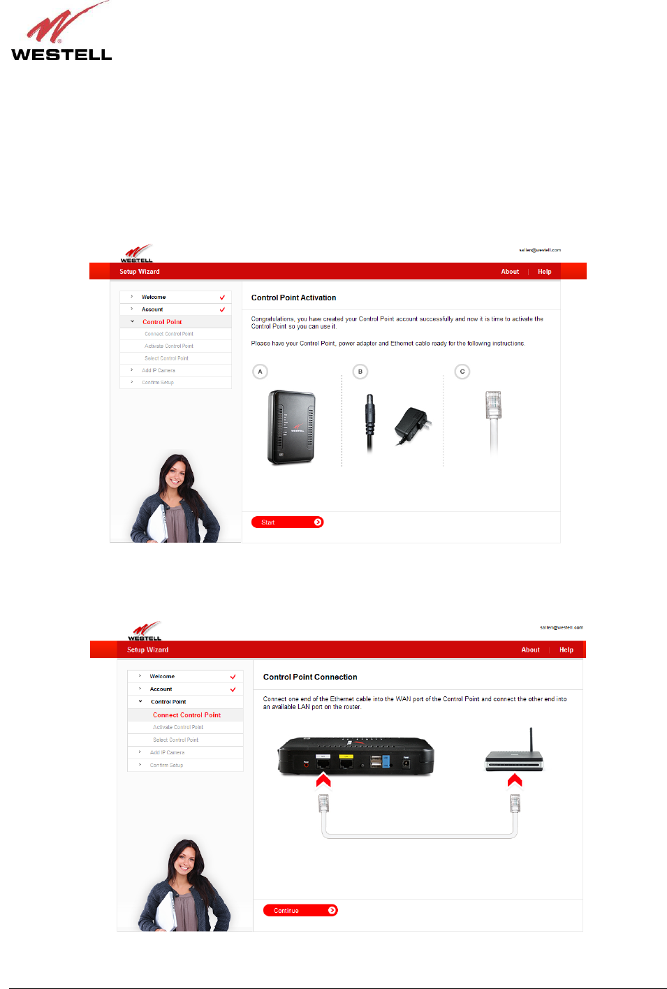
030-300589 Rev. A 21 March 2009
User Guide Control Point Home Monitorin
g
Service
7.4 Activating Your Control Point
To begin your Control Point activation, first confirm that the router (to which you have connected the Control Point)
is powered on, connected to the Internet, and functioning properly. If needed, refer section 6, “Installing the
Hardware,” of this User Guide for installation details.
Before starting this section, please have your Control Point, power adapter, and Ethernet cable ready.
Click Start to proceed.
The following page appears. Connect one end of the Ethernet cable into the WAN port of the Control Point, and
then connect the other end of the Ethernet cable into an available LAN port on your gateway or router. Click
Continue to proceed.
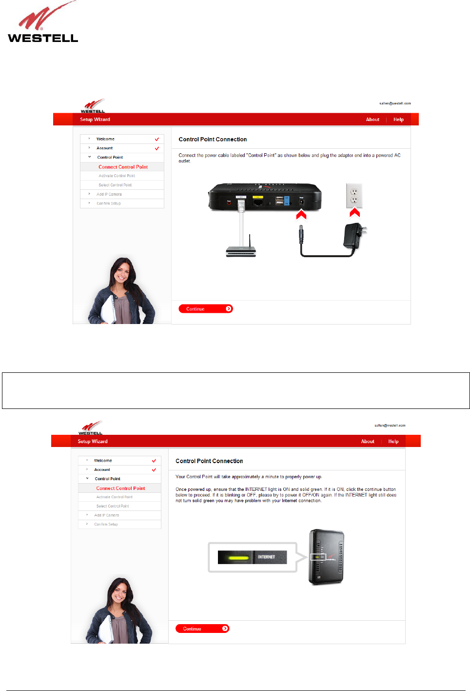
030-300589 Rev. A 22 March 2009
User Guide Control Point Home Monitorin
g
Service
Next, connect the small end of the power adapter into power connector on the Control Point, and then plug the other
end into your AC wall outlet. Click Continue to proceed.
Your Control Point will take approximately a minute to properly power up. Once powered up, check to ensure that
the INTERNET LED is On and solid green. If it is On, click the Continue button in the following page to proceed.
NOTE: If the INTERNET LED is blinking or Off, power the Control Point Off and then On again. If the
INTERNET LED still does not light solid green, you may have a problem with your Internet connection. Please
check your network connections. If problems persist, contact your service provider for further instructions.
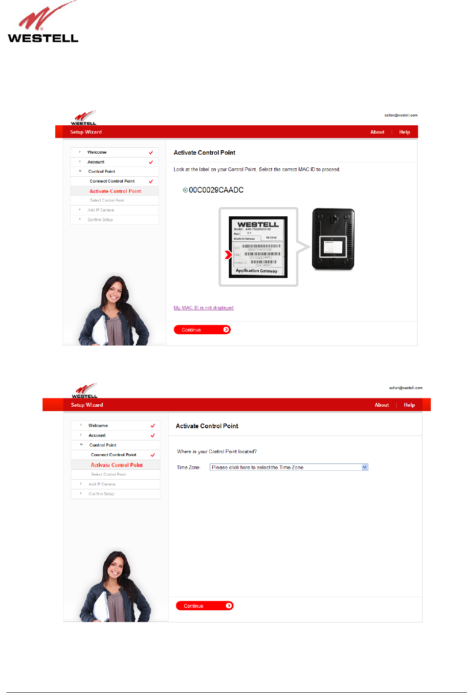
030-300589 Rev. A 23 March 2009
User Guide Control Point Home Monitorin
g
Service
Look at the label located on the bottom of your Control Point. Your Control Point’s MAC ID is displayed in the
label below the MAC bar code. In the following page, click the radio button of the ID that matches your Control
Point’s MAC ID. Click Continue to proceed.
Next, from the Time Zone drop-down list, select the time zone for your area. Click Continue to proceed.
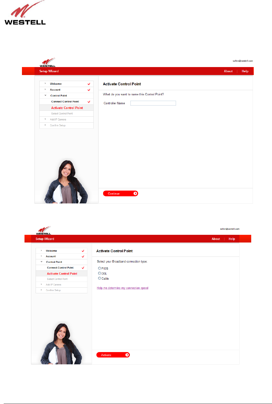
030-300589 Rev. A 24 March 2009
User Guide Control Point Home Monitorin
g
Service
The following page allows you to name your Control Point. Type the desired name in the Controller Name field,
and then click Continue to proceed.
In the following page, click the radio button next to your Broadband connection type.
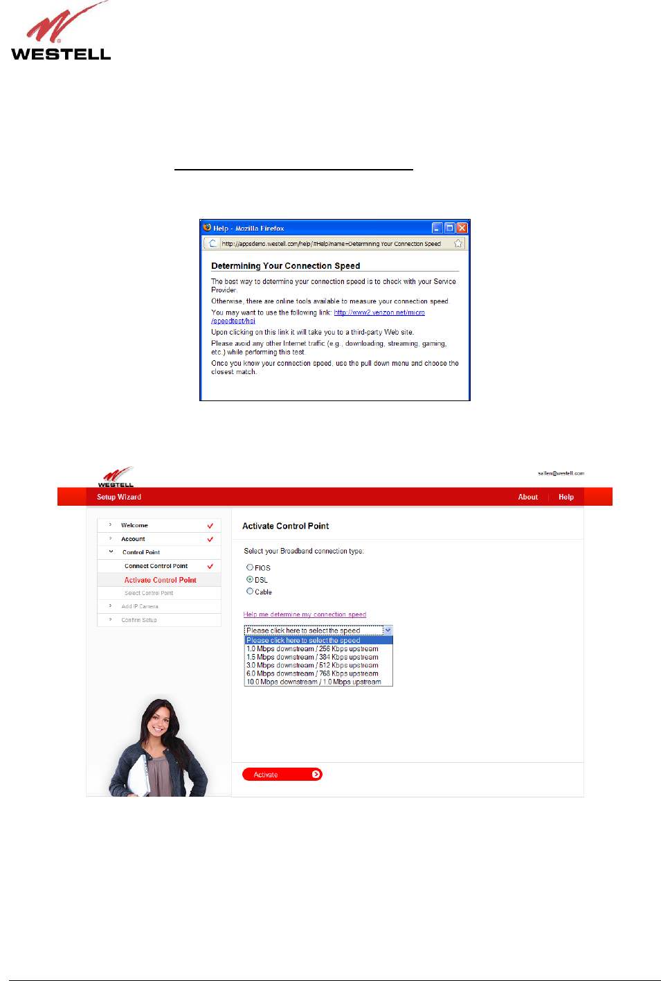
030-300589 Rev. A 25 March 2009
User Guide Control Point Home Monitorin
g
Service
Your Control Point will request that you select a connection speed. If you are unsure, the best way to determine your
connection speed is to check with your service provider. Also, there are links available on the Internet that can
measure your connection speed.
For example, if you click the Help me determine my connection speed link, following pop-up screen appears.
Clicking the link in the pop-up screen takes you to a third-party Web site that can help determine your connection
speed.
After you have selected your Broadband connection type, go to the drop-down list in the following page and select
the connection speed that is the closest match to your connection speed. Then click Activate to proceed.
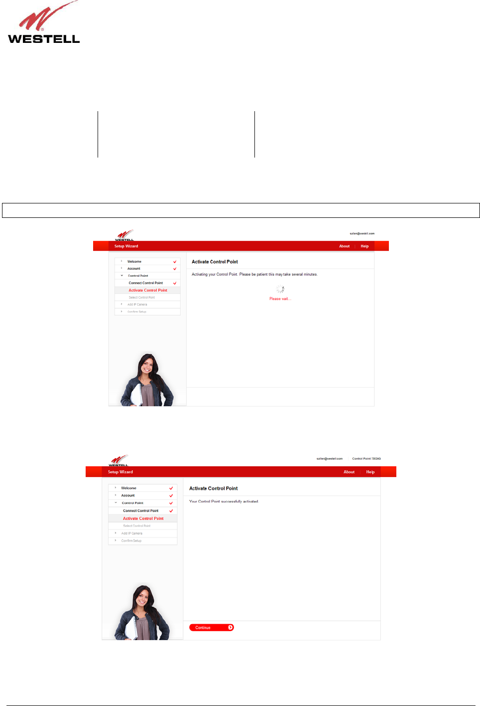
030-300589 Rev. A 26 March 2009
User Guide Control Point Home Monitorin
g
Service
Your Control Point will begin the activation process. While your Control Point is being activated, the Control
Point’s POWER and SERVICE LEDs will display the following behavior:
Control Point LED While Control Point is activating After Control Point has been activated
POWER Solid red Solid green
SERVICE Flashing green Solid green
The page below will appear while your Control Point is being activated.
IMPORTANT: Please wait for the Control Point activation to complete, which may take several minutes.
After your Control Point has been successfully activated, the following page appears. Click Continue to proceed.
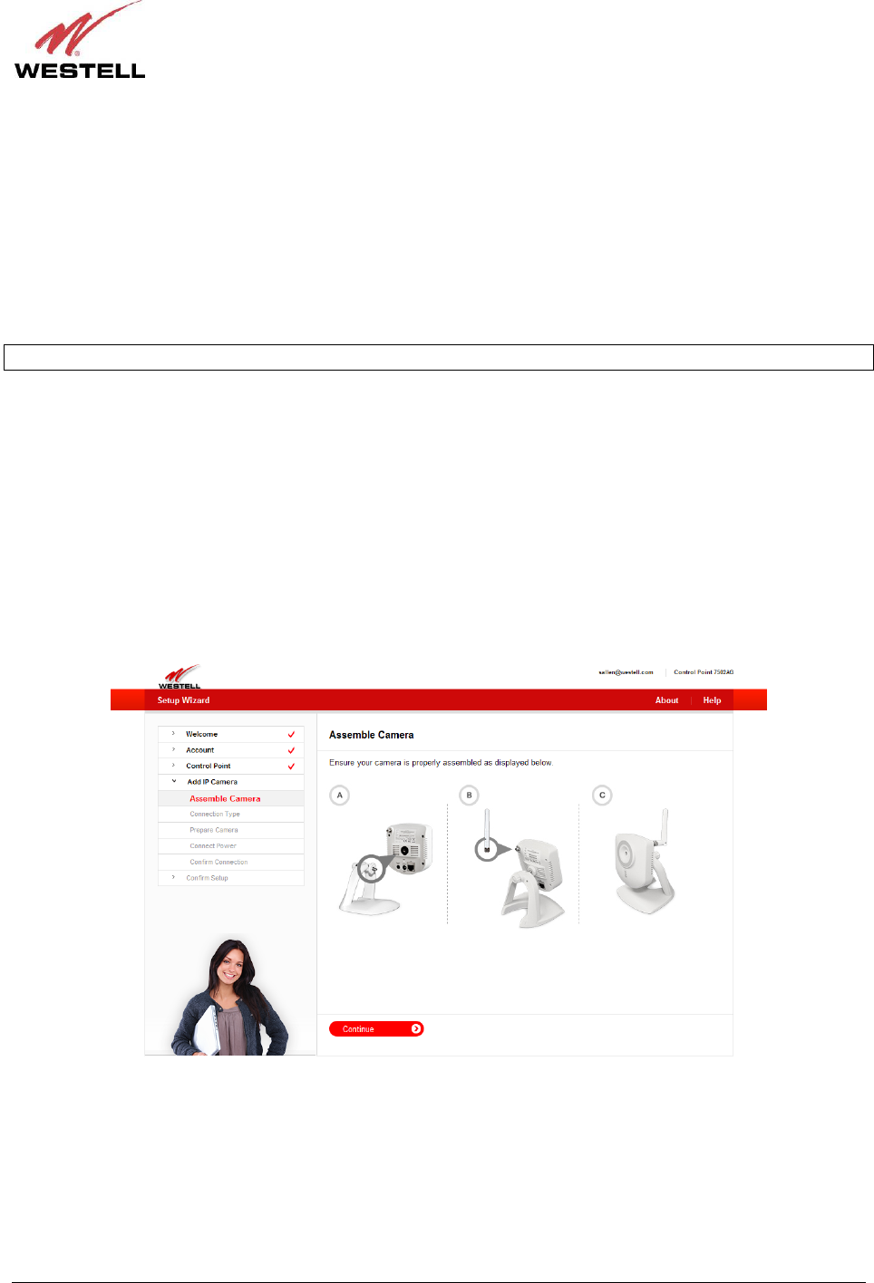
030-300589 Rev. A 27 March 2009
User Guide Control Point Home Monitorin
g
Service
7.5 Setting Up Your 7521FF Camera
If you haven’t already assembled your 7521FF Camera, please take a moment to assemble it now. In section 7.5.1,
“Assembling Your Camera,” the Setup Wizard will walk you through these steps. Otherwise, if you have already
assembled your Camera, go to section 7.5.3, “I Have Already Assembled the Camera,” for further instructions.
7.5.1 Assembling Your Camera
IMPORTANT: Please do not power on the Camera or connect any cables to the Camera until instructed to do so.
To assembly your 7521FF Camera, please complete these steps. The following illustration is provided to help guide
you through the assembly.
A. Align the threaded hole on the back of the Camera with the screw on the Camera stand, and then turn the
Camera until it is firmly screwed on to the stand.
B. Screw the wireless antenna onto the connector located on the back of the Camera. Make sure the antenna is
firmly locked into place.
C. Orient the antenna to appropriate position.
After you have assembled the Camera, you should be able to tilt the Camera to the desired position. Click Continue
to proceed.
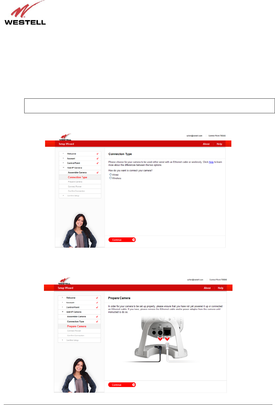
030-300589 Rev. A 28 March 2009
User Guide Control Point Home Monitorin
g
Service
7.5.2 Connecting Your Camera
The following page allows you to choose how you want to connect your Camera to your Control Point.
• “Wired” setup means that an Ethernet cable will be plugged in from the router to the Camera at all times.
• “Wireless” setup means that you will be able to relocate your Camera to another part of your home after
you have properly set up your Camera.
NOTE: The typical range for a wireless setup of your Camera is 30-50 ft., and you could have issues
seeing video if the recommended distance between the Camera and the router is exceeded.
Click the radio button of the method you want to use, and then click Continue to proceed.
In order for your Camera to be set up properly, please do not power on the Camera or connect any cables until you
are instructed to do so. Click Continue to proceed.
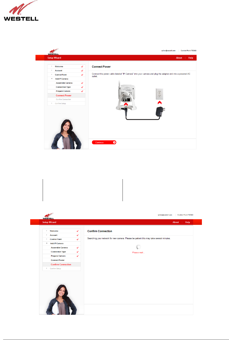
030-300589 Rev. A 29 March 2009
User Guide Control Point Home Monitorin
g
Service
Next, connect the Camera’s power adapter to the Camera and to your AC wall outlet. After you have connected the
power adapter, click Continue to proceed.
Please wait while your Control Point searches the network for your Camera. During the search, the Camera LEDs
will display the following behavior:
Camera LED While Searching for the Camera After the Camera has been detected
Power Flashing green Solid green
Network Flashing green Flashing green (streaming video to the browser)
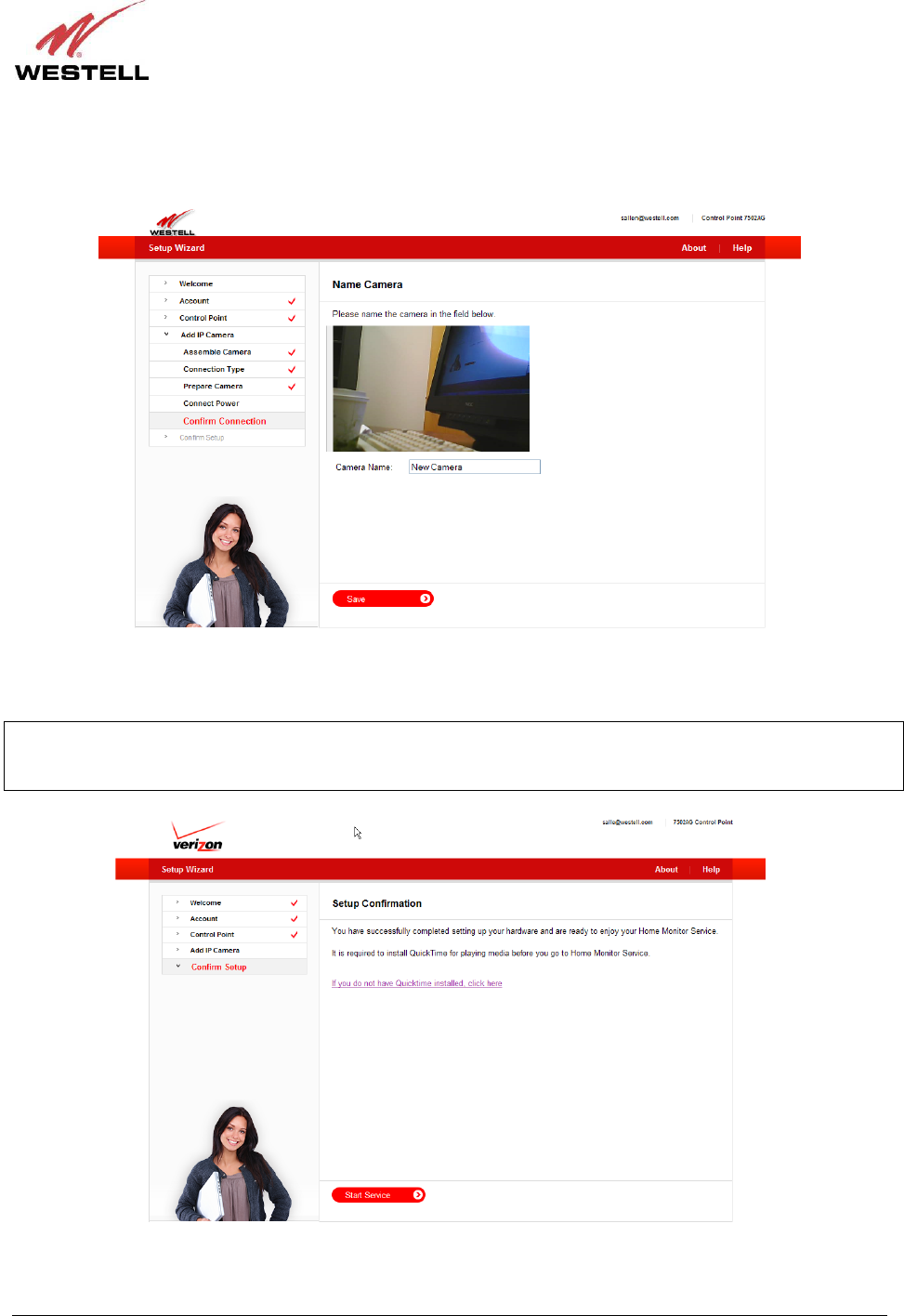
030-300589 Rev. A 30 March 2009
User Guide Control Point Home Monitorin
g
Service
After Control Point has detected your Camera, the following page appears. Type the desired name for your Camera
in the Camera Name field, and then click Save to proceed.
Congratulations! You have successfully completed your Camera setup. Now you are ready to use your Control Point
Home Monitor Service. Click Start Service to proceed.
IMPORTANT: It is required that you have the QuickTime media player installed for before using your Home
Monitor Service. If you don’t have QuickTime installed, click the link in this page to download a copy of QuickTime.
Alternatively, you can download a version of the QuickTime media player from the Internet.
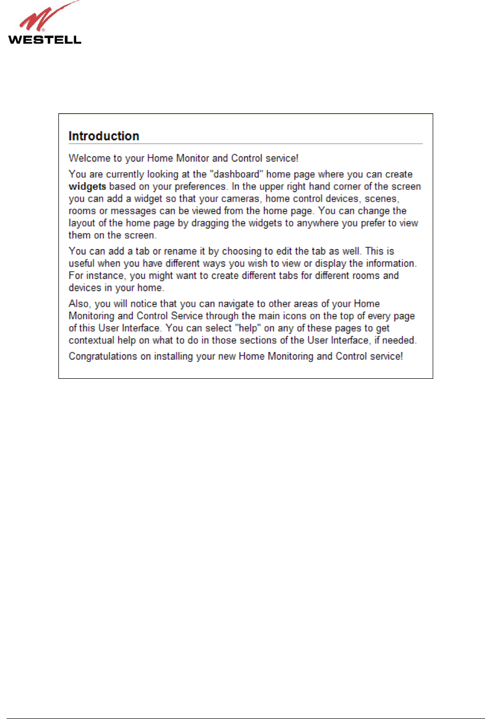
030-300589 Rev. A 31 March 2009
User Guide Control Point Home Monitorin
g
Service
After your Control Point has been successfully activated. The following Introduction briefly appears. Then the
Control Point Home page appears. The Home page will be explained in section 9 of this User Guide. Please proceed
to section 8 for instructions on accessing your Control Point User Interface.
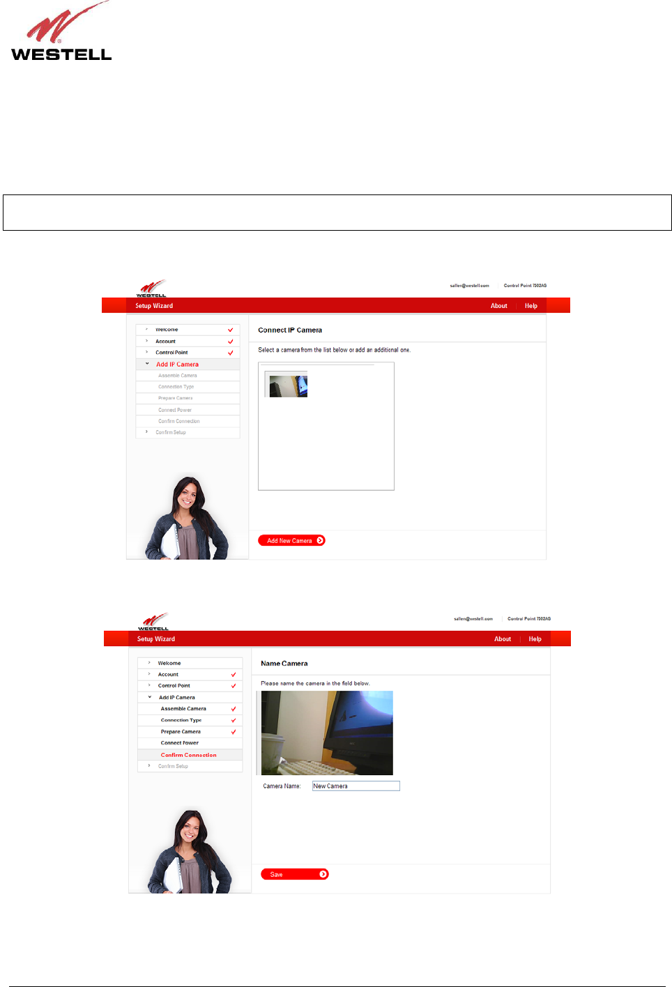
030-300589 Rev. A 32 March 2009
User Guide Control Point Home Monitorin
g
Service
7.5.3 I Have Already Assembled the Camera
If you have already assembled and installed your Camera as explained earlier in sections 6.3.2 and 6.3.3, the
following page appears after your Control Point has been activated. In this page, select the IP camera you want to
add to your Control Point.
NOTE: You can have more than one IP camera connected to your Control Point. If you have other IP cameras
connected, the page below will display a list of the IP Cameras connected to your Control Point.
Click the image of the IP Camera you want to select, and then click Add New Camera to continue.
Next, type the desired name for your Camera in the Camera Name field, and then click Save to continue.
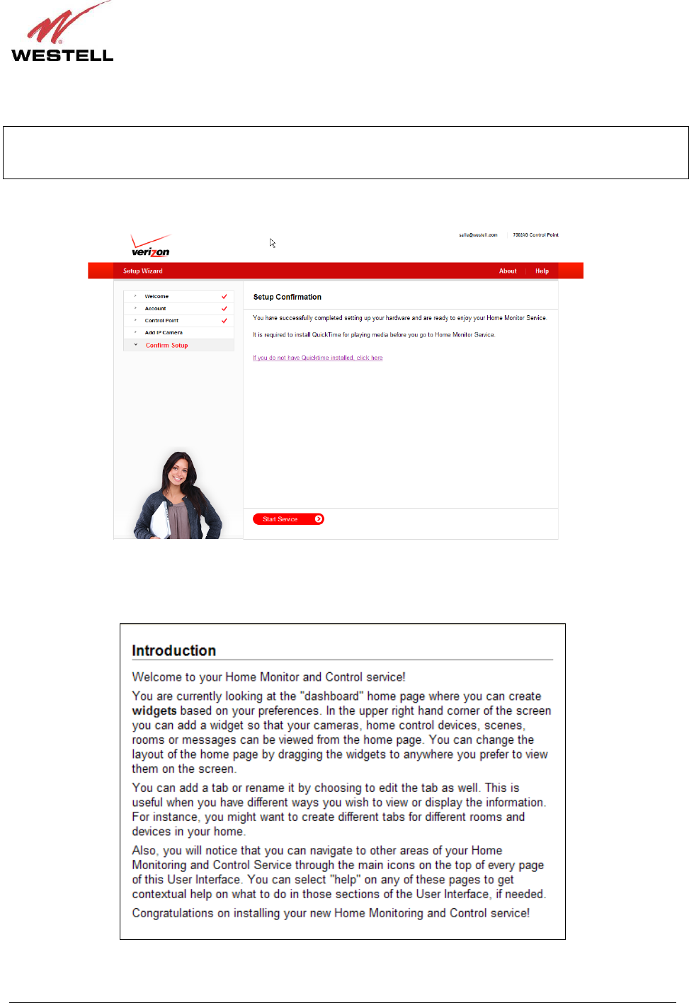
030-300589 Rev. A 33 March 2009
User Guide Control Point Home Monitorin
g
Service
Congratulations! You have successfully completed your Camera setup.
IMPORTANT: It is required that you have the QuickTime media player installed for before using your Home
Monitor Service. If you don’t have QuickTime installed, click the link in this page to download a copy of QuickTime.
Alternatively, you can download a version of the QuickTime media player from the Internet.
Now you are ready to use your Control Point Home Monitor Service. Click Start Service to proceed.
The following Introduction briefly appears. Then the Control Point Home page appears. The Home page will be
explained in section 9 of this User Guide. Please proceed to section 8 for instructions on accessing your Control
Point User Interface.