Wireless Seismic 00103 Wireless Remote Unit User Manual DeploymentGuide
Wireless Seismic, Inc. Wireless Remote Unit DeploymentGuide
Contents
- 1. Users Manual 1
- 2. Users Manual 2
Users Manual 1

Draft
RT System 2
Deployment Guide
June 21, 2012
Part Number: 90-0018
R00.e

Draft
To order additional copies of this document, send an email to your sales representative
requesting the following:
Part Number: 90-0018-PDF
Part Number: 90-0018-Paper
Real Time Matters
Corporate Headquarters: 13100 Southwest Freeway, Suite 150 Sugar Land, TX 77478 USA 832-532-5080
Regional Office: 1172 West Century Drive, Suite 200 Louisville, CO 80027 USA 720-242-9916
info@wirelessseismic.com www.wirelessseismic.com
© 2010-2012 Wireless Seismic, Inc. All rights reserved.
All other brands, company names, product names, trademarks or service marks referenced in this material are the
property of their respective owners, who may or may not be affiliated with, connected to, or sponsored by Wireless
Seismic, Inc.
Wireless Seismic, Inc.'s trademarks, registered trademarks or trade dress may not be used in connection with any
product or service that is not the property of Wireless Seismic, Inc., in any manner that is likely to cause confusion
among customers, or in any manner that disparages or discredits Wireless Seismic, Inc. The products and services
described in this material may not be available in all regions.

Draft
RT System 2 v2.0.0 3 Deployment Guide R00.e
© 2010-2012 Wireless Seismic, Inc. All rights reserved.
Table of Contents
1.1. Overview . . . . . . . . . . . . . . . . . . . . . . . . . . . . . . . . . . . . . . . . . . 9
1.1 About this Guide . . . . . . . . . . . . . . . . . . . . . . . . . . . . . . . . . . . . . . 9
1.2 Who Should Use this Guide . . . . . . . . . . . . . . . . . . . . . . . . . . . . . . . 9
1.3 Related Documents . . . . . . . . . . . . . . . . . . . . . . . . . . . . . . . . . . . . 9
1.4 Getting Help . . . . . . . . . . . . . . . . . . . . . . . . . . . . . . . . . . . . . . . . . 9
2.2. Layout . . . . . . . . . . . . . . . . . . . . . . . . . . . . . . . . . . . . . . . . . . . .11
2.1 Prerequisites . . . . . . . . . . . . . . . . . . . . . . . . . . . . . . . . . . . . . . . . 11
2.2 Getting Ready . . . . . . . . . . . . . . . . . . . . . . . . . . . . . . . . . . . . . . . 11
2.3 Preparing the Equipment. . . . . . . . . . . . . . . . . . . . . . . . . . . . . . . . 12
2.4 Laying Out the Equipment. . . . . . . . . . . . . . . . . . . . . . . . . . . . . . . 12
2.4.1 Prerequisites. . . . . . . . . . . . . . . . . . . . . . . . . . . . . . . . . . . . . 15
2.4.2 Assembling the Ground Equipment . . . . . . . . . . . . . . . . . . . . . 17
2.4.3 Placing the WRU in the Field . . . . . . . . . . . . . . . . . . . . . . . . . . 20
2.4.4 Placing the LIU in the Field . . . . . . . . . . . . . . . . . . . . . . . . . . . 22
3.3. Backhaul . . . . . . . . . . . . . . . . . . . . . . . . . . . . . . . . . . . . . . . . . .23
3.1 Overview. . . . . . . . . . . . . . . . . . . . . . . . . . . . . . . . . . . . . . . . . . . 23
3.2 Backhaul Components . . . . . . . . . . . . . . . . . . . . . . . . . . . . . . . . . 26
3.2.1 LIU Components . . . . . . . . . . . . . . . . . . . . . . . . . . . . . . . . . . 26
3.2.1.1 LIU . . . . . . . . . . . . . . . . . . . . . . . . . . . . . . . . . . . . . . . . 26
3.2.1.2 Battery and Power Supply . . . . . . . . . . . . . . . . . . . . . . . . 28
3.2.1.3 Cables. . . . . . . . . . . . . . . . . . . . . . . . . . . . . . . . . . . . . . 28
3.2.2 Antennas . . . . . . . . . . . . . . . . . . . . . . . . . . . . . . . . . . . . . . . 29
3.2.3 Radio Kit Components . . . . . . . . . . . . . . . . . . . . . . . . . . . . . . 29
3.2.3.1 FM1100 Radio . . . . . . . . . . . . . . . . . . . . . . . . . . . . . . . . 31
3.2.3.2 FM3100 Radio . . . . . . . . . . . . . . . . . . . . . . . . . . . . . . . . 31
3.2.3.3 Radio Install Kit . . . . . . . . . . . . . . . . . . . . . . . . . . . . . . . 32
3.2.4 Mast Kit Components. . . . . . . . . . . . . . . . . . . . . . . . . . . . . . . 33
3.2.4.1 Mast . . . . . . . . . . . . . . . . . . . . . . . . . . . . . . . . . . . . . . . 34
3.2.4.2 Base . . . . . . . . . . . . . . . . . . . . . . . . . . . . . . . . . . . . . . . 34
3.2.4.3 Bag. . . . . . . . . . . . . . . . . . . . . . . . . . . . . . . . . . . . . . . . 36
3.2.4.4 Backpack Kit . . . . . . . . . . . . . . . . . . . . . . . . . . . . . . . . . 36
3.3 Turn off the Windows Firewall . . . . . . . . . . . . . . . . . . . . . . . . . . . . 36
3.4 Configure the Radios . . . . . . . . . . . . . . . . . . . . . . . . . . . . . . . . . . 38
3.4.1 Create a Private Network . . . . . . . . . . . . . . . . . . . . . . . . . . . . 38
3.4.2 Setting NIC Priority . . . . . . . . . . . . . . . . . . . . . . . . . . . . . . . . 44
3.4.3 Configure the Radio. . . . . . . . . . . . . . . . . . . . . . . . . . . . . . . . 45
3.4.4 Restore your Network Settings . . . . . . . . . . . . . . . . . . . . . . . . 49
3.4.5 Using the Fluidmesh Interface to Scan . . . . . . . . . . . . . . . . . . . 49
3.4.6 Using the Fluidmesh Interface to Ping . . . . . . . . . . . . . . . . . . . 49

Draft
4 RT System 2 v2.0.0 Deployment Guide R00.e
© 2010-2012 Wireless Seismic, Inc. All rights reserved.
Table of Contents
3.5 Setting up the Backhaul Equipment. . . . . . . . . . . . . . . . . . . . . . . . .49
3.6 Installing Two Radios on the Mast . . . . . . . . . . . . . . . . . . . . . . . . . .53
3.7 Removing the Backhaul Equipment . . . . . . . . . . . . . . . . . . . . . . . . .54
3.8 Use Cases or Example Deployments . . . . . . . . . . . . . . . . . . . . . . . .54
4.4. Demobilization . . . . . . . . . . . . . . . . . . . . . . . . . . . . . . . . . . . . . 58
4.1 Overview . . . . . . . . . . . . . . . . . . . . . . . . . . . . . . . . . . . . . . . . . . .58
4.2 Removing the WRU from the Field. . . . . . . . . . . . . . . . . . . . . . . . . .58
4.3 Disassemble the WRU . . . . . . . . . . . . . . . . . . . . . . . . . . . . . . . . . .59
5.5. Maintaining the Equipment. . . . . . . . . . . . . . . . . . . . . . . . . . . . 61
5.1 Units . . . . . . . . . . . . . . . . . . . . . . . . . . . . . . . . . . . . . . . . . . . . . .61
5.2 Antennas . . . . . . . . . . . . . . . . . . . . . . . . . . . . . . . . . . . . . . . . . . .61
5.3 Geophones . . . . . . . . . . . . . . . . . . . . . . . . . . . . . . . . . . . . . . . . . .61
5.4 Cautions. . . . . . . . . . . . . . . . . . . . . . . . . . . . . . . . . . . . . . . . . . . .61
6.6. Troubleshooting and Tips . . . . . . . . . . . . . . . . . . . . . . . . . . . . . 62
6.1 Best Practices . . . . . . . . . . . . . . . . . . . . . . . . . . . . . . . . . . . . . . . .62
6.1.1 24 Ah Batteries . . . . . . . . . . . . . . . . . . . . . . . . . . . . . . . . . . .62
6.1.2 LIU . . . . . . . . . . . . . . . . . . . . . . . . . . . . . . . . . . . . . . . . . . . .62
6.1.3 Urban Environments . . . . . . . . . . . . . . . . . . . . . . . . . . . . . . . .62
6.1.4 Ethernet Cables . . . . . . . . . . . . . . . . . . . . . . . . . . . . . . . . . . .62
6.1.5 Fiber Optic Cables . . . . . . . . . . . . . . . . . . . . . . . . . . . . . . . . .63
6.1.6 Antennas. . . . . . . . . . . . . . . . . . . . . . . . . . . . . . . . . . . . . . . .63
6.2 Troubleshooting . . . . . . . . . . . . . . . . . . . . . . . . . . . . . . . . . . . . . .64
6.2.1 Backhaul Troubleshooting Flow . . . . . . . . . . . . . . . . . . . . . . . .64
6.2.2 Fluidmesh Radios . . . . . . . . . . . . . . . . . . . . . . . . . . . . . . . . . .64
7.7. Batteries. . . . . . . . . . . . . . . . . . . . . . . . . . . . . . . . . . . . . . . . . . 66
7.1 Lithium Ion Batteries . . . . . . . . . . . . . . . . . . . . . . . . . . . . . . . . . . .66
7.1.1 Specifications. . . . . . . . . . . . . . . . . . . . . . . . . . . . . . . . . . . . .66
7.1.2 Handling and Safety Guidelines . . . . . . . . . . . . . . . . . . . . . . . .67
7.1.3 Transportation . . . . . . . . . . . . . . . . . . . . . . . . . . . . . . . . . . . .68
7.1.4 Storage. . . . . . . . . . . . . . . . . . . . . . . . . . . . . . . . . . . . . . . . .69
7.2 Charging Lithium Ion Batteries . . . . . . . . . . . . . . . . . . . . . . . . . . . .70
7.2.1 Charging Precautions . . . . . . . . . . . . . . . . . . . . . . . . . . . . . . .70
7.2.2 Battery Charger . . . . . . . . . . . . . . . . . . . . . . . . . . . . . . . . . . .71
7.3 LIU Battery. . . . . . . . . . . . . . . . . . . . . . . . . . . . . . . . . . . . . . . . . .72
8.8. Batteries. . . . . . . . . . . . . . . . . . . . . . . . . . . . . . . . . . . . . . . . . . 73
8.1 Batteries au lithium-ion . . . . . . . . . . . . . . . . . . . . . . . . . . . . . . . . .73
8.1.1 Spécifications. . . . . . . . . . . . . . . . . . . . . . . . . . . . . . . . . . . . .73
8.1.2 Directives en matière de manipulation et de sécurité . . . . . . . . .74
8.1.3 Transport . . . . . . . . . . . . . . . . . . . . . . . . . . . . . . . . . . . . . . .75
8.1.4 Entreposage . . . . . . . . . . . . . . . . . . . . . . . . . . . . . . . . . . . . .77
8.2 Chargement des batteries au lithium-ion . . . . . . . . . . . . . . . . . . . . .78
8.2.1 Précautions de chargement . . . . . . . . . . . . . . . . . . . . . . . . . . .78
8.2.2 Chargeur de batterie. . . . . . . . . . . . . . . . . . . . . . . . . . . . . . . .78

Draft
R00.e RT System 2 v2.0.0 Deployment Guide 5
© 2010-2012 Wireless Seismic, Inc. All rights reserved.
Table of Contents
8.3 LIU de batterie. . . . . . . . . . . . . . . . . . . . . . . . . . . . . . . . . . . . . . . 80
A.A. Legal Information . . . . . . . . . . . . . . . . . . . . . . . . . . . . . . . . . . .81
A.1 FCC Rules and Regulations Compliance. . . . . . . . . . . . . . . . . . . . . . 81
A.2 Industry Canada Compliance. . . . . . . . . . . . . . . . . . . . . . . . . . . . . 82
B.B. l'information juridique. . . . . . . . . . . . . . . . . . . . . . . . . . . . . . . .83
B.1 Conformité avec les règles et règlements de la FCC . . . . . . . . . . . . . 83
B.2 Industrie Canada Conformité. . . . . . . . . . . . . . . . . . . . . . . . . . . . . 84
C.C. Fluidmesh Radio Specifications . . . . . . . . . . . . . . . . . . . . . . . . .85
C.1 The Fluidmesh Mito Series. . . . . . . . . . . . . . . . . . . . . . . . . . . . . . . 85
C.2 Fluidmesh 1100 with MITO Technology. . . . . . . . . . . . . . . . . . . . . . 87
C.3 Fluidmesh 3100 with MITO Technology. . . . . . . . . . . . . . . . . . . . . . 88
C.4 MITO Series General Characteristics. . . . . . . . . . . . . . . . . . . . . . . . 89
D.D. LED Indicators. . . . . . . . . . . . . . . . . . . . . . . . . . . . . . . . . . . . . .91
E.E. Weighted Mast . . . . . . . . . . . . . . . . . . . . . . . . . . . . . . . . . . . . . .98
E.1 Specifications. . . . . . . . . . . . . . . . . . . . . . . . . . . . . . . . . . . . . . . . 98
E.2 Hardware Supplied. . . . . . . . . . . . . . . . . . . . . . . . . . . . . . . . . . . . 99
E.3 Assembly Instructions. . . . . . . . . . . . . . . . . . . . . . . . . . . . . . . . . . 99
Index . . . . . . . . . . . . . . . . . . . . . . . . . . . . . . . . . . . . . . . . . . . . . . .101

Draft
6 RT System 2 v2.0.0 Deployment Guide R00.e
© 2010-2012 Wireless Seismic, Inc. All rights reserved.
List of Figures
List of Figures
Figure 2–1 WRU .............................................................................................13
Figure 2–2 LIU ...............................................................................................14
Figure 2–3 WRU with Geophone........................................................................15
Figure 2–4 Assembling WRUs ...........................................................................16
Figure 2–5 Battery Latch .................................................................................18
Figure 2–6 Installing the Battery.......................................................................18
Figure 2–7 Installing the Geophone................................................................... 19
Figure 2–8 Antenna with Spring Relief ...............................................................19
Figure 2–9 Power on the Unit ...........................................................................21
Figure 2–10 Place the Unit.................................................................................21
Figure 3–1 Possible LIU Components.................................................................24
Figure 3–2 Central Recording Truck Components ................................................24
Figure 3–3 Single Backhaul Data Direction .........................................................25
Figure 3–4 Line Interface Unit (LIU)..................................................................27
Figure 3–5 LIU Ground ....................................................................................28
Figure 3–6 Channel Color Example....................................................................30
Figure 3–7 FM1100 Radio ................................................................................ 31
Figure 3–8 FM3100 Radio ................................................................................ 31
Figure 3–9 Surge Protector Connections.............................................................32
Figure 3–10 Fiberglass Mast (55-0008)................................................................34
Figure 3–11 Base (55-0007) .............................................................................. 35
Figure 3–12 Assembled Backhaul Mast ................................................................35
Figure 3–13 Weighted Base (70-0070) ................................................................36
Figure 3–14 Windows Firewall On or Off ..............................................................37
Figure 3–15 Windows Firewall Off.......................................................................37
Figure 3–16 Fluidmesh Radio Private Network ......................................................39
Figure 3–17 Control Panel, Network and Internet..................................................40
Figure 3–18 Control Panel, Network and Sharing Center ........................................40
Figure 3–19 Control Panel, Change Adapter Settings.............................................41
Figure 3–20 Control Panel, LAN Properties ...........................................................41
Figure 3–21 Control Panel, Networking Properties.................................................42
Figure 3–22 Control Panel, IP Address.................................................................43
Figure 3–23 Advanced Network Settings Menu .....................................................44
Figure 3–24 LAN Hierarchy ................................................................................45
Figure 3–25 Radio Login Window........................................................................46
Figure 3–26 Radio Home Window, Mesh End ........................................................47
Figure 3–27 Fluidmesh MeshWizard Interface.......................................................48
Figure 3–28 Mast on a Slope..............................................................................50
Figure 3–29 Base and Wind Orientation...............................................................51
Figure 3–30 Securing Lines to Large Cleat ...........................................................52
Figure 3–31 Backhaul Antenna Erected................................................................52
Figure 3–32 Two-Radio Installation.....................................................................53
Figure 3–33 Single Backhaul..............................................................................55
Figure 3–34 Dual Backhaul, Two Root Nodes........................................................56
Figure 3–35 Single Backhaul, Star Configuration...................................................57
Figure 4–1 Power Off the Unit...........................................................................58
Figure 4–2 Undeployed Unit .............................................................................59
Figure 4–3 Removing the Battery......................................................................60
Figure 6–1 Fiber Optic Cable Connector .............................................................63

Draft
R00.e RT System 2 v2.0.0 Deployment Guide 7
© 2010-2012 Wireless Seismic, Inc. All rights reserved.
List of Figures
Figure 6–2 Troubleshooting – Check LIU.............................................................64
Figure 6–3 Troubleshooting – Check Fluidmesh Radios .........................................64
Figure 7–1 Example Battery Shipping Label ........................................................69
Figure 7–2 Battery Charger ..............................................................................71
Figure 7–3 Serial Number Label and LED Indicator...............................................72
Figure E–1 Weighted Mast................................................................................98
Figure E–2 Tripod Assembly – Front View ...........................................................99

Draft
8 RT System 2 v2.0.0 Deployment Guide R00.e
© 2010-2012 Wireless Seismic, Inc. All rights reserved.
List of Tables
List of Tables
Table 3–1 Line Interface Unit Kit (15-0041) ......................................................26
Table 3–2 Antenna Specifications.....................................................................29
Table 3–3 Radio Kit Components .....................................................................29
Table 3–4 Radio Install Kit..............................................................................32
Table 3–5 Mast Kit.........................................................................................33
Table 3–6 Fluidmesh Radio LEDs......................................................................39
Table 6–1 Troubleshooting Fluidmesh Radios.....................................................65
Table 7–1 Lithium Ion Battery Specifications .....................................................66
Table A–1 Antenna Specifications.....................................................................81
Table D–1 5Mbps WRU Power On Sequence LED Indications ................................91
Table D–2 WRU LED Status Indications.............................................................93
Table D–3 WRU LED Error Indications...............................................................95
Table D–4 LIU LED Discipline Indications...........................................................96

Draft
RT System 2 v2.0.0 9 Deployment Guide R00.e
© 2010-2012 Wireless Seismic, Inc. All rights reserved.
1
1. Overview
1.1 About this Guide
This document provides information on how to deploy the RT System 2 in the
field. See the RT System 2 Installation Guide for instructions on setting up the
recording truck equipment and software.
1.2 Who Should Use this Guide
The expected users of this document are as follows:
Crew (Layout/Troubleshooters)
Technician (LIU)
Bosses (Line Crew)
1.3 Related Documents
RT System 2-related documents are as follows:
RT System 2 Documents Guide (90-0026) – Lists all of the RT System 2
documents with a brief description of each.
RT System 2 Glossary (90-0032) – Lists and defines RT System 2 terms
and acronyms. Includes some general seismic and geologic terms and
acronyms.
RT System 2 Installation Guide (90-0028) – Provides instructions for
setting up the recording truck hardware, and installing and updating
software and firmware.
1.4 Getting Help
To get help on the RT System 2 Central Recording System, consult the online
help. You can find the help documents by clicking the help icon in the user
interface, or by navigating to the following directory:
C:\wsi\rt\vx.y.z\server\help\index.htm
Where vx.y.z is the version number (for example, v2.0.0).
To get help on the RT System 2 deployment, consult this document.

Draft
10 RT System 2 v2.0.0 Deployment Guide R00.e
© 2010-2012 Wireless Seismic, Inc. All rights reserved.
1. Overview
Getting Help
If you cannot find the answers you need, please contact Wireless Seismic, Inc.
Customer Support at:
13100 Southwest Freeway, Suite 150
Sugar Land, TX 77478
(832) 532-5048
support@wirelessseismic.com

Draft
RT System 2 v2.0.0 11 Deployment Guide R00.e
© 2010-2012 Wireless Seismic, Inc. All rights reserved.
2
2. Layout
This chapter describes how to prepare (mobilization) and layout (install) the
ground electronics. See the RT System 2 Installation Guide for instructions on
setting up the recording truck equipment and software.
2.1 Prerequisites
In preparation for mobilization, define the following:
Survey
Backhaul plan
2.2 Getting Ready
Collect all of the following:
RT System 2 ground equipment (05-0007):
●5 Mbps WRUs (10-0017)
●LIUs (see “Backhaul Components” on page 26)
●One of the following antennas:
►9 dBi antenna (65-0067)
►7 dBi antenna (6060-001-01)
►5 dBi antenna (65-0023)
►2 dBi antenna (65-0025)
●Geophones
●WRU Batteries (0400-001-01)
●WRU Dummy Batteries (55-0009)
●Antenna Extenders
●Fiber Backhaul
●Tools
●Manuals
NOTE
Please refer to “Antenna Specifications” on page 81 for the list of
supported antennas. Use of accessories other than those specified in
this document is not supported or warrantied.

Draft
12 RT System 2 v2.0.0 Deployment Guide R00.e
© 2010-2012 Wireless Seismic, Inc. All rights reserved.
2. Layout
Preparing the Equipment
●Consumables
●Spares (15-0003)
►Mast Parts
►Base Parts
►Guy Lines
►Antennas
►Batteries
►Cables
►Connectors
2.3 Preparing the Equipment
Ensure that the central recording system has the latest software available installed
(see the RT System 2 Release Notes for version numbers, see the RT System 2
Installation Guide for installation and update instructions).
Ensure that the ground equipment has the latest firmware available installed (see
the RT System 2 Release Notes for version numbers, see the RT System 2
Installation Guide for installation and update instructions).
Ensure that the industry standard best practices are followed for securing the
equipment for transport.
2.4 Laying Out the Equipment
You can lay out the ground equipment while the central recording system
hardware and software is being prepared.
NOTE
The batteries (when fully discharged) require 8 hours of continuous
charging in the battery charger connected to an AC source; therefore,
the battery charger should be located at the staging area or in town.
Draft
R00.e RT System 2 v2.0.0 Deployment Guide 13
© 2010-2012 Wireless Seismic, Inc. All rights reserved.
2. Layout
Laying Out the Equipment
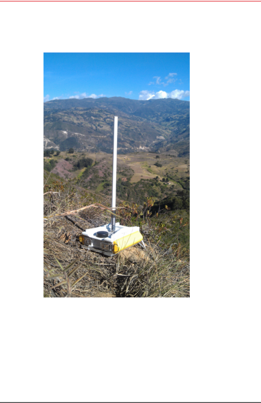
The WRU is shown in the following figure:
Figure 2–1 WRU
Draft
14 RT System 2 v2.0.0 Deployment Guide R00.e
© 2010-2012 Wireless Seismic, Inc. All rights reserved.
2. Layout
Laying Out the Equipment
The LIU is shown in the following figure:
Figure 2–2 LIU

Draft
R00.e RT System 2 v2.0.0 Deployment Guide 15
© 2010-2012 Wireless Seismic, Inc. All rights reserved.
2. Layout
Laying Out the Equipment
An example geophone is shown in the following figure
2.4.1 Prerequisites
You can attach the batteries, antennas, and geophones to the ground equipment
prior to going into to the field, or as you place each unit. If you are assembling as
you place the units, ensure that you have sufficient quantities for each unit, plus a
few spares.
Figure 2–3 WRU with Geophone

Draft
16 RT System 2 v2.0.0 Deployment Guide R00.e
© 2010-2012 Wireless Seismic, Inc. All rights reserved.
2. Layout
Laying Out the Equipment
The RT System 2 shall be used with only the supplied antennas (Table A–1
Antenna Specifications, on page 81) attached to the WRU with an integrated type
N male connector.
The RT System 2 antennas shall be installed and handled by professionals
specifically designated for this purpose.
Changes or modifications not expressly approved by Wireless Seismic, Inc. can
void the users’s authority to operate the equipment.
Figure 2–4 Assembling WRUs

Draft
R00.e RT System 2 v2.0.0 Deployment Guide 17
© 2010-2012 Wireless Seismic, Inc. All rights reserved.
2. Layout
Laying Out the Equipment
2.4.2 Assembling the Ground Equipment
This section describes the process to assemble the ground equipment prior to
deployment.
To assemble the ground equipment:
1Gather the equipment:
●WRU
●Antenna
●Geophone
●Batteries
2Gather any special tools:
●Optional: Nylon grip pliers
●Optional: Loctite® 222
3Attach one or more batteries to the WRU.
●Press the battery into the connector.
●Flip the bail over the molded area on the end of the battery.
●Press the lever until the catch snaps to lock it in place.
WARNING
In order to comply with FCC radio frequency (RF) exposure
requirements, the RT System 2 units must be installed so that a
minimum separation distance of 20 cm is maintained between the
antenna(s) and the body of all persons at all times during normal
operation.
WARNING
AVERTISSEM
ENT
Afin de se conformer aux normes de la FCC en matière d'exposition aux
radiofréquences (RF), les unités RT System 2 doivent être installées de
manière à garder en permanence une distance minimale de 20 cm entre
la ou les antennes et le corps de toute personne en mode de
fonctionnement normal.

Draft
18 RT System 2 v2.0.0 Deployment Guide R00.e
© 2010-2012 Wireless Seismic, Inc. All rights reserved.
2. Layout
Laying Out the Equipment
4Attach the geophone to the WRU.
Figure 2–5 Battery Latch
Figure 2–6 Installing the Battery

Draft
R00.e RT System 2 v2.0.0 Deployment Guide 19
© 2010-2012 Wireless Seismic, Inc. All rights reserved.
2. Layout
Laying Out the Equipment
5Attach the antenna to the WRU. Ensure that the antenna connection is clean,
and the antenna is snug and does not wobble.
Figure 2–7 Installing the
Geophone
TIP
The antenna screws on to the WRU in a clockwise direction. It should
twist on easily; do not use force. To ensure that the threads are
properly aligned, turn the connector counter-clockwise until you hear a
click indicating that the threads are aligned, then turn clockwise to
tighten.
Figure 2–8 Antenna with Spring Relief

Draft
20 RT System 2 v2.0.0 Deployment Guide R00.e
© 2010-2012 Wireless Seismic, Inc. All rights reserved.
2. Layout
Laying Out the Equipment
2.4.3 Placing the WRU in the Field
This section describes the process to ready the ground equipment for interaction
with the central recording system (deployment).
To deploy the WRU:
1Prerequisites:
●The WRU is assembled with battery, geophone, and antenna
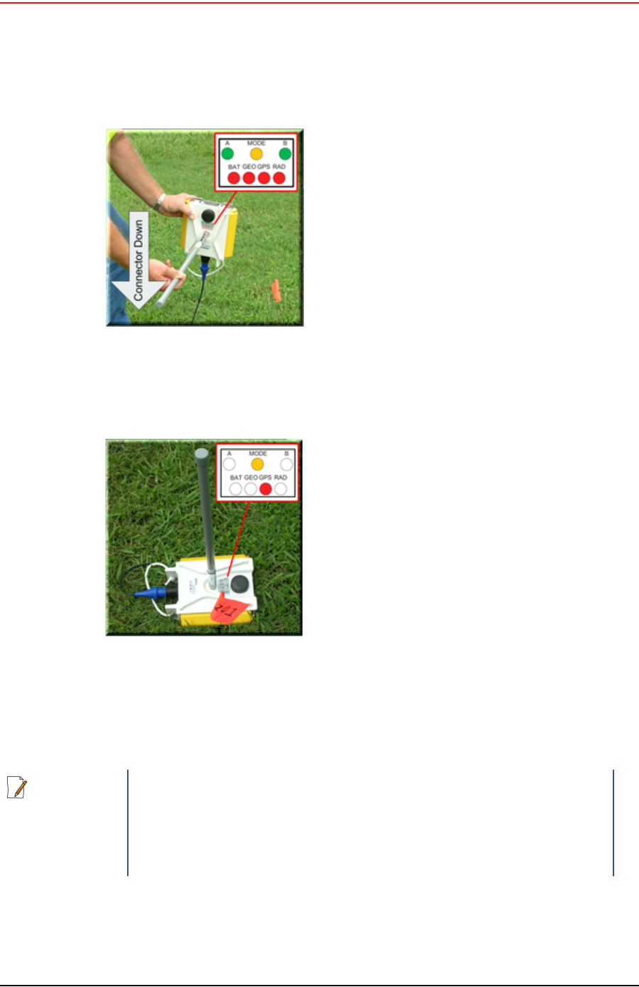
2Pick up the WRU and point the geophone connector end towards the ground as
shown in the following figure. After a few seconds, all of the LEDs illuminate:
TIP
When determining which antenna to use (5 dBi, 7 dBi, 9dBi), consider
the distance between WRUs, and how much vegetation is in the area.
For distances of 10 m to 30 m, use a 5 dBi antenna.
Distances of 30 m or greater, use a 7 dBi antenna.
For sudden elevation changes, such as cliffs, use a 2 dBi or 5 dBi
antenna.
In special situations such as tall grass and dense vegetation, or
distances of 55 m or greater, use a 9 dBi antenna.
NOTE
If you are using a WRU as a Repeater, the deployment instructions are
the same, except a geophone is not required. Repeaters are added to
the line segment in the Spread Manager. See the RT System 2 Operator
Guide for more information.
If a geophone is not connected, you can skip the geophone test. See
“D. LED Indicators” on page 91 for more information on skipping the
test and the relevant LED status indicators.
Draft
R00.e RT System 2 v2.0.0 Deployment Guide 21
© 2010-2012 Wireless Seismic, Inc. All rights reserved.
2. Layout
Laying Out the Equipment
3Place the unit flat on the ground as shown in the following figure:
4The unit will begin a series of internal and external tests. The LEDs on the top
of the unit indicate the current test and whether the unit passes or fails each
test.
Figure 2–9 Power on the Unit
Figure 2–10 Place the Unit
NOTE
See “D. LED Indicators” on page 91 for an explanation of the LED status
and error conditions.
If a WRU self test fails, the WRU will continue to the next test.
You can skip a self-test by tipping the WRU geophone down and then
returning it to the upright position (flat on the ground).

Draft
22 RT System 2 v2.0.0 Deployment Guide R00.e
© 2010-2012 Wireless Seismic, Inc. All rights reserved.
2. Layout
Laying Out the Equipment
2.4.4 Placing the LIU in the Field
The LIU is part of the backhaul configuration. See “3. Backhaul” on page 23 for
more information.

Draft
RT System 2 v2.0.0 23 Deployment Guide R00.e
© 2010-2012 Wireless Seismic, Inc. All rights reserved.
3
3. Backhaul
3.1 Overview
In network communications, the backhaul is the part of the network that
contains the links and equipment between the core network and the sub
networks.
Wireless mesh networking is a method where each radio node in the network
captures and disseminates its own data as well as serves as a relay for other
radio nodes in the network sending data along a path, hopping from one node
to the next.
Power over Ethernet (PoE) is a technology that passes electrical power along
an Ethernet cable. PoE is used where DC power is not available and USB
unsuitable. Power can be supplied at the end of a network span or somewhere
in the middle.
PoE switches supply power at the end of a span. The RT System 2 Line
Interface Unit acts as a switch with PoE.
PoE injectors supply power somewhere between the PoE switch and the
powered device. They inject power and do not affect the data. A discrete PoE
injector is used when configuring the Fluidmesh radios.
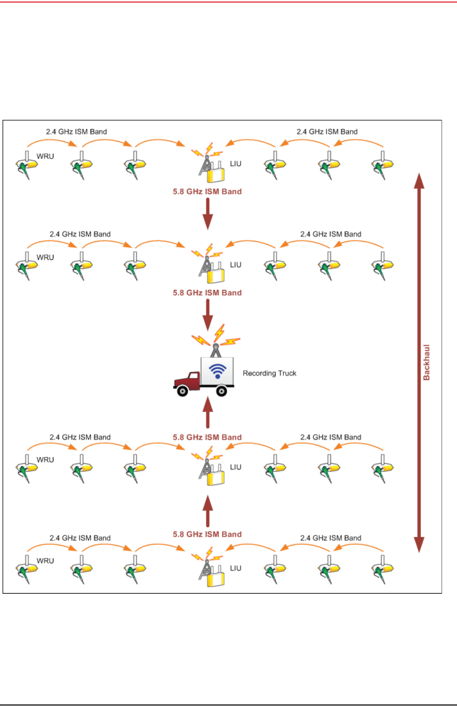
The RT System 2 Central Recording System is a fully connected mesh network
of Wireless Remote Units (WRUs) that communicate in a relay pattern (bucket-
brigade or string-of-pearls) with a Line Interface Unit (LIU) on the 2.4 GHz
Industrial, Scientific, and Medical (ISM) radio band.
The LIU is composed of the following discrete components:
Line Interface Unit (LIU) box
12 V DC, 5 A capable Battery or Power Supply
Cables
Mast, mast base, and guy-wires
5.8 GHz backhaul radios
Antennas
The LIU communicates with the Central Software System (CSS) computer in
the central recording truck along a backhaul on the 900 MHz or 5.8 GHz ISM
radio band. Some smaller systems may not require a backhaul.
The Central Software System (CSS) communicates with the field units via the
backhaul radios. The backhaul radios act as access points for the LIUs.
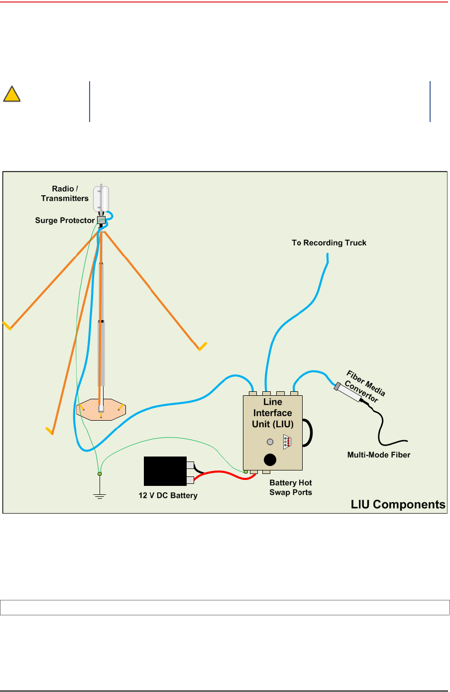
The following figure illustrates the possible LIU components:
Draft
24 RT System 2 v2.0.0 Deployment Guide R00.e
© 2010-2012 Wireless Seismic, Inc. All rights reserved.
3. Backhaul
Overview
The following figure illustrates the central recording truck components:
CAUTION
Ensure that the LIU box has a grounding cable attached that is
connected to a grounding rod to avoid causing damage to the internal
electronics during use. See “LIU Ground” on page 28 for an illustration.
Figure 3–1 Possible LIU Components
TBD
Figure 3–2 Central Recording Truck Components
Draft
R00.e RT System 2 v2.0.0 Deployment Guide 25
© 2010-2012 Wireless Seismic, Inc. All rights reserved.
3. Backhaul
Overview
The following figure illustrates the components and data flow for a four-line,
single-backhaul line with two root nodes example:
Figure 3–3 Single Backhaul Data Direction

Draft
26 RT System 2 v2.0.0 Deployment Guide R00.e
© 2010-2012 Wireless Seismic, Inc. All rights reserved.
3. Backhaul
Backhaul Components
3.2 Backhaul Components
The backhaul components are either remote backhaul components or central
backhaul components. Remote components are the components that are not
physically located next to the recording truck. Central components are physically
located at the recording truck. Both remote and central backhauls are composed of
the following:
Line Interface Unit (LIU) Kit
Antenna
Radio Kit
Mast Kit
3.2.1 LIU Components
The following table lists the LIU kit components:
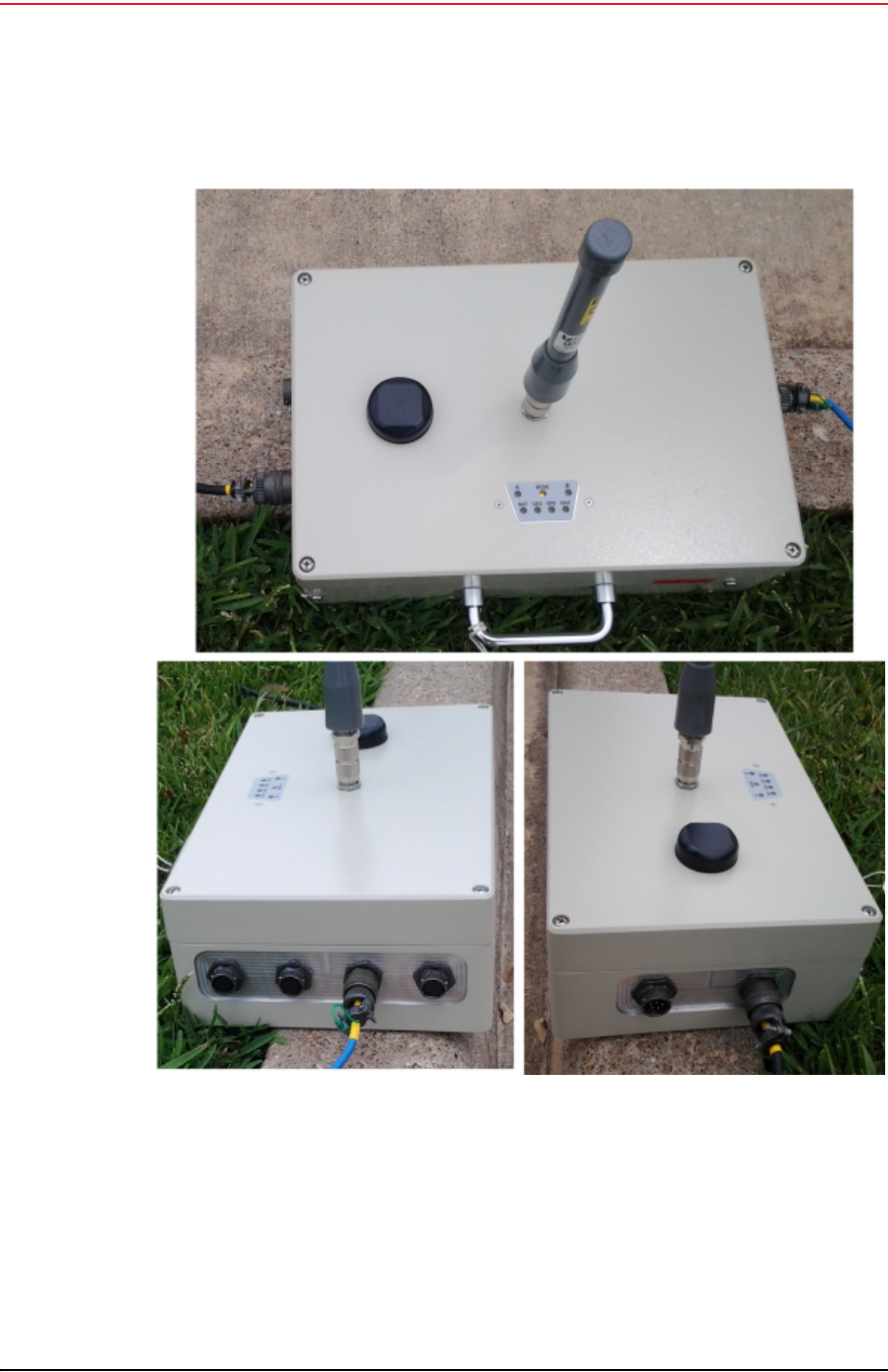
3.2.1.1 LIU
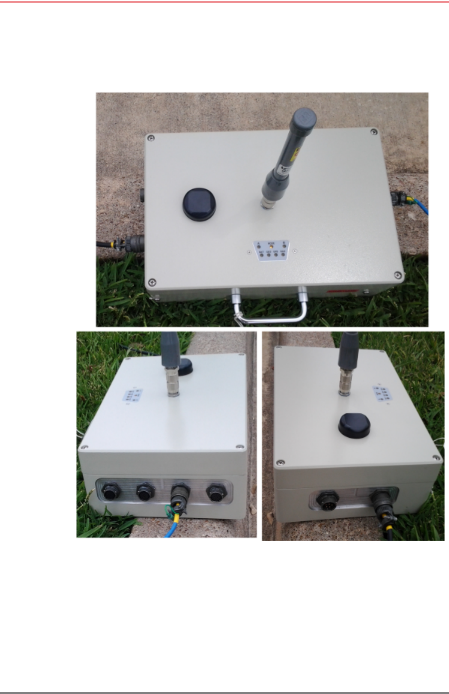
The data transmitted by the WRUs is collected by the Line Interface Unit (LIU).
The LIU acts as the interface between the network of WRUs and the backhaul
equipment. The LIU has an Ethernet port that can be connected directly to a
computer, or more commonly, to an armored fiber optic cable or a backhaul radio.
Backhaul radios operate in the 900 MHz or 5.8 GHz bands. A second array of WRUs
can be deployed on the other side of the LIU, symmetrically or asymmetrically
around the LIU. The LIU is shown in the following figure:
Table 3–1 Line Interface Unit Kit (15-0041)
Remote Backhaul Components Central Backhaul Components
Item Reference Item Reference
LIU (10-0016) “LIU” on page
26 LIU (10-0016) “LIU” on page
26
12 V DC Battery or power
supply (not included) “Battery and
Power Supply”
on page 28
12 V DC Battery or power
supply (not included) “Battery and
Power Supply”
on page 28
Cable, LIU to Battery (60-
0034) “Cables” on
page 28 Cable, LIU to Battery (60-
0034) “Cables” on
page 28
Cable, Ethernet (60-0036, 60-
0037, 60-0038) “Cables” on
page 28 Cable, Ethernet (60-0036, 60-
0037, 60-0038) “Cables” on
page 28
Cable, LIU-to-PC (60-0039) “Cables” on
page 28 Cable, LIU-to-PC (60-0039) “Cables” on
page 28
Draft
R00.e RT System 2 v2.0.0 Deployment Guide 27
© 2010-2012 Wireless Seismic, Inc. All rights reserved.
3. Backhaul
Backhaul Components
Figure 3–4 Line Interface Unit (LIU)

Draft
28 RT System 2 v2.0.0 Deployment Guide R00.e
© 2010-2012 Wireless Seismic, Inc. All rights reserved.
3. Backhaul
Backhaul Components
Before the Central Software System can communicate with the LIU, you must set
up the backhaul.
Ensure that the LIU is grounded. Attach a ground wire to the case, and to a nail
that is driven into the ground.
The ground wire is illustrated in the following figure:
3.2.1.2 Battery and Power Supply
Power is supplied to the LIU components by way of a 12 V DC battery or power
supply.
3.2.1.3 Cables
The following cables are used in the backhaul:
LIU to Battery (60-0034)
Ethernet Cable, 30 ft (65-0036)
Ethernet Cable, 60 ft (60-0037)
Ethernet Cable, 120 ft (60-0038)
Cable, LIU-to-PC (60-0039)
Fiber Optic Cable
NOTE
See “D. LED Indicators” on page 91 for an explanation of the LED status
and error conditions.
CAUTION
Attach the LIU ground wire and the Surge Protector ground wire to the
same nail.
Figure 3–5 LIU
Ground
TIP
The backhaul power requirements vary depending on the hardware in
use and period of use. For example, you may be using one or two
radios. Supply enough power to ensure there is enough power for the
entire duration of the time you are using the backhaul.

Draft
R00.e RT System 2 v2.0.0 Deployment Guide 29
© 2010-2012 Wireless Seismic, Inc. All rights reserved.
3. Backhaul
Backhaul Components
●Media Converter (60-0017)
●Cable, Backhaul Jumper (60-0033)
●Cable, Fiber Optic, Armored, 250 m (60-0026)
●Cable, Fiber Optic, Armored, 300 m (60-0024)
●Cable, Fiber Optic, Armored, 500 m (60-0023)
●Cable, Fiber Optic, 500 m (60-0018)
3.2.2 Antennas
The following table lists the supported antennas for the LIUs and the WRUs. The
remote and central backhauls use the same antennas:
The Fluidmesh radios have built-in antennas (see “Radio Kit Components” on page
29 for details).
There is an auto-power-leveling feature built into the firmware. It works in
conjunction with the RSSI parameters to keep the power at a defined level.
3.2.3 Radio Kit Components
The following table lists the Radio Kit components:
Table 3–2 Antenna Specifications
Model Frequency
(MHz) Gain Vertical
Beam
Width Weight Dimension
(Length x
Diameter)
WSI 65-0067 2400-2485 9 dbi 14° 0.8 lbs
0.5 kg 27 x 0.6 in
690 x 15 mm
WSI 6060-001-01 2400-2485 7 dBi 18° 0.6 lbs
0.3 kg 21 x 0.6 in
540 x 15 mm
WSI 65-0023 2400-2485 5 dBi 25º 0.5 lbs
0.2 kg 12 x 0.6 in
355 x 15 mm
WSI 65-0025 2400-2485 2 dBi @ 2.4 120° 1.6 oz
45.4 g 7.6 x 0.5 in
193 x 12.7 mm
WSI 65-0082 2400-2485 7.4 dBi 20º 5.4 oz
153 g 18.5 x 0.75 in
470 x 19 mm
WSI 65-0131 2400-2485 4 dBi 50º 3.2 oz
90 g 8.7 x 0.75 in
221 x 19 mm
Table 3–3 Radio Kit Components
Item Reference
Radio, Fluidmesh® FM1100 (75-0014) “FM1100 Radio” on page 31
Draft
30 RT System 2 v2.0.0 Deployment Guide R00.e
© 2010-2012 Wireless Seismic, Inc. All rights reserved.
3. Backhaul
Backhaul Components
Refer to the Fluidmesh datasheet for FCC information and other technical
specifications on the FM1100 and FM3100 radios. See one of the following
locations for details:
http://www.fluidmesh.com/press-room/product-literature/doc_details/160-
fluidmesh-mito-series
“C. Fluidmesh Radio Specifications” on page 85
The Fluidmesh radios can operate on at 4.9 GHz, and 5.1 - 5.8 GHz. The preferred
frequency is configured through a user interface (see “Configure the Radios” on
page 38 for instructions).
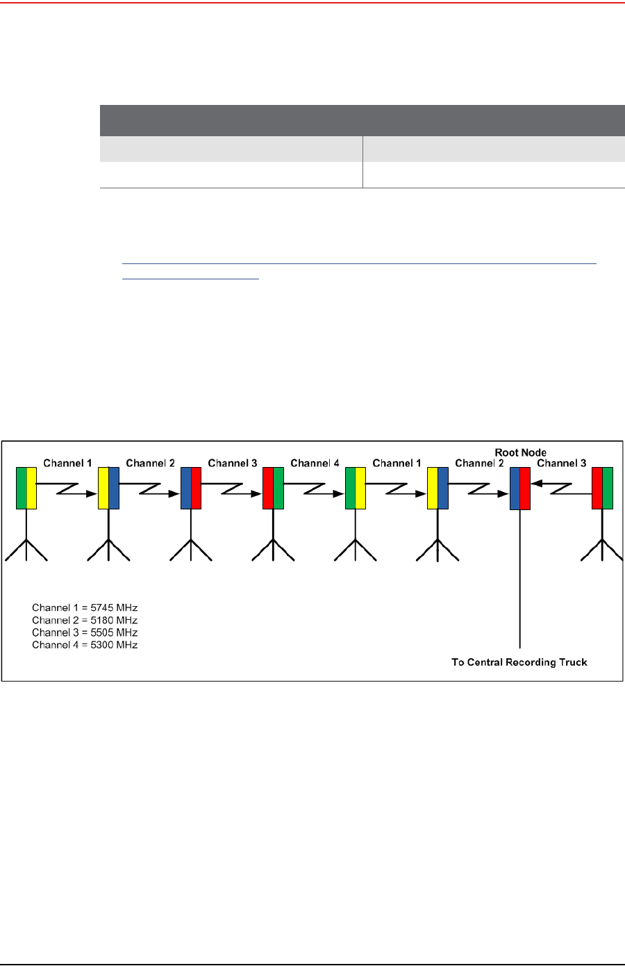
Each radio is assigned a color that represents the channel assignment, allowing
field personnel to quickly orient the radios in the proper direction. An example is
shown in the following figure:
The Fluidmesh default IP address is 192.168.0.10.
Radio, Fluidmesh® FM3100 (75-0014) “FM3100 Radio” on page 31
Radio Install Kit (15-0036) “Radio Install Kit” on page 32
Table 3–3 Radio Kit Components (cont.)
Item Reference
Figure 3–6 Channel Color Example
Draft
R00.e RT System 2 v2.0.0 Deployment Guide 31
© 2010-2012 Wireless Seismic, Inc. All rights reserved.
3. Backhaul
Backhaul Components
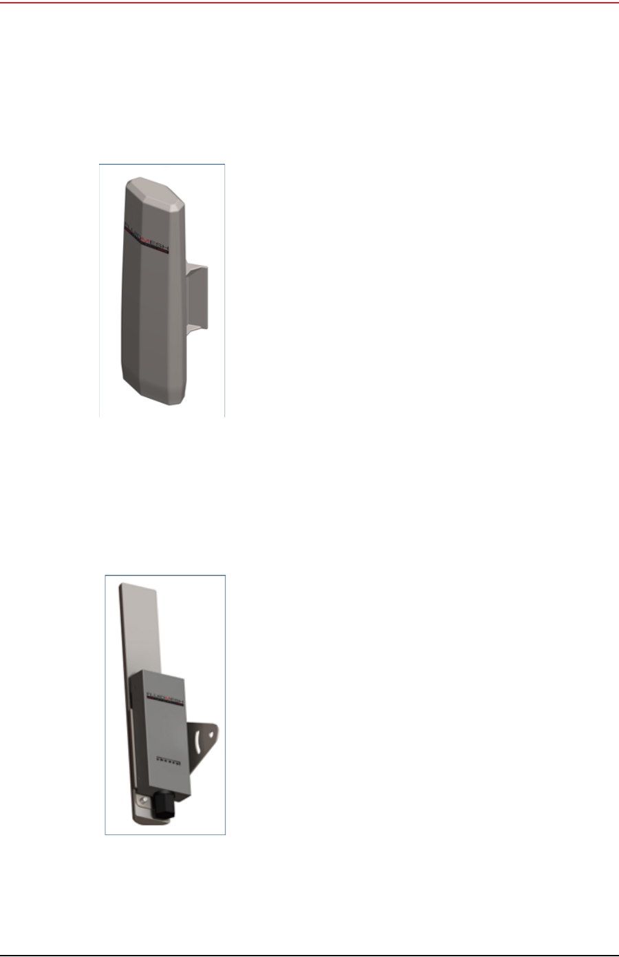
3.2.3.1 FM1100 Radio
The FM1100 radio is used on the masts for the remote backhauls and is shown in
the following figure. Attach the radio to the mast with a hose clamp.
3.2.3.2 FM3100 Radio
The FM3100 is used on the masts for the central backhaul unit and is shown in the
following figure. Attach the radio to the mast with a hose clamp.
Figure 3–7 FM1100
Radio
Figure 3–8 FM3100
Radio

Draft
32 RT System 2 v2.0.0 Deployment Guide R00.e
© 2010-2012 Wireless Seismic, Inc. All rights reserved.
3. Backhaul
Backhaul Components
3.2.3.3 Radio Install Kit
The following table lists the Radio Install Kit components. The remote and central
backhauls use the same install components.
The following figure illustrates the inside of the Surge Protector.
Table 3–4 Radio Install Kit
Item Reference
Surge Protector (75-0021) “Surge Protector
Connections” on page 32
Wire, 18 AWG PVC Green (65-0077) —
Nail, 12 inch (70-0062) —
Hose Clamp, 0.5 inch (70-0084) —
Ethernet Cable, CAT5E, 3 foot, shielded (65-0104) —
Figure 3–9 Surge Protector
Connections
NOTE
Install one Surge Protector for each Ethernet cable that runs down the
mast and connects to another component.

Draft
R00.e RT System 2 v2.0.0 Deployment Guide 33
© 2010-2012 Wireless Seismic, Inc. All rights reserved.
3. Backhaul
Backhaul Components
To install the Surge Protector:
1Remove the rubber grommet from the case and cut some slots in it.
2Thread two Ethernet cables and a ground wire through the grommet and place
the grommet back in the case.
3Plug the Ethernet cables into the shielded RJ45 jacks. It does not matter which
cable goes to which jack; the unit provides bidirectional protection.
4Attach the ground wire to the ground lug.
5Close the case and attach it to the mast with a hose clamp.
6Attach one of the Ethernet cables to the radio.
7Attach the other Ethernet cable to the LIU.
8Attach the ground wire to a nail and press the nail into the ground.
3.2.4 Mast Kit Components
The following table lists the Mast Kit components. The remote and central
backhauls use the same mast kit components.
The Weighted Base (70-0070) is a separate component (see “Base” on page 34).
CAUTION
Attach the LIU ground wire and the Surge Protector ground wire to the
same nail.
TIP
See “Possible LIU Components” on page 24 for an illustration that
shows the Surge Protector installed on a mast.
Table 3–5 Mast Kit
Fiberglass Kit (15-0004) Aluminum Kit (15-0033) Reference
Mast, fiberglass (55-0008) Mast, aluminum (70-0081) “Mast” on page 34
Base (55-0007) Base (55-0007) “Base” on page 34
Bag (70-0058) Bag (70-0058) “Bag” on page 36
Backpack Kit (15-0014) Backpack Kit (15-0014) “Backpack Kit” on page 36
• 1 each backpack (70-0059) • 1 each backpack (70-0059) “Backpack Kit” on page 36
• 3 each guy lines, rope, orange,
15.25 meters (70-0057) • 3 each guy lines, rope, orange,
15.25 meters (70-0057) “Backpack Kit” on page 36
• 3 each tent stake, steel, 12 in
(70-0061) (hard ground
stakes)
• 3 each tent stake, steel, 12 in
(70-0061) (hard ground
stakes)
“Backpack Kit” on page 36
Draft
34 RT System 2 v2.0.0 Deployment Guide R00.e
© 2010-2012 Wireless Seismic, Inc. All rights reserved.
3. Backhaul
Backhaul Components
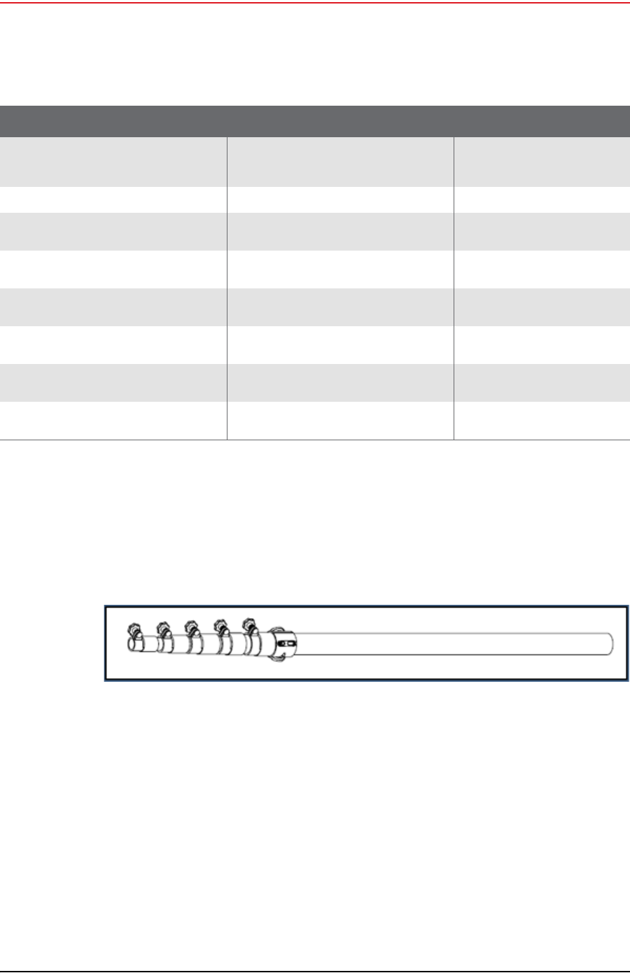
3.2.4.1 Mast
Lightweight, telescoping backhaul masts are used to elevate the backhaul
components above obstructions and to enable radio communications to
accommodate typical cross-line distances. The mast can be installed by a single
person. The following figures show the mast:
3.2.4.2 Base
There are two base options; one that requires the use of guy wires for stabilization
and one that uses weights for stabilization.
• 3 each tent stake, plastic,
orange, 16 in (70-0060) (soft
ground stakes)
• 3 each tent stake, plastic,
orange, 16 in (70-0060) (soft
ground stakes)
“Backpack Kit” on page 36
• 5 ea nail, 12 in (70-0062) • 5 ea nail, 12 in (70-0062) “Backpack Kit” on page 36
• 3 each guy line holder (70-
0063) • 3 each guy line holder (70-
0063) “Backpack Kit” on page 36
• 1 each hammer, 2.5 lb (70-
0064) • 1 each hammer, 2.5 lb (70-
0064) “Backpack Kit” on page 36
• 1 each pry bar, 15 in (70-
0065) • 1 each pry bar, 15 in (70-
0065) “Backpack Kit” on page 36
• 2 each flagging roll, orange
(70-0066) • 2 each flagging roll, orange
(70-0066) “Backpack Kit” on page 36
• 1 each compass sighting (70-
0067) • 1 each compass sighting (70-
0067) “Backpack Kit” on page 36
• 5 each hose clamp, 2 in (70-
0068) • 5 each hose clamp, 2 in (70-
0068) “Backpack Kit” on page 36
Table 3–5 Mast Kit (cont.)
Fiberglass Kit (15-0004) Aluminum Kit (15-0033) Reference
Figure 3–10 Fiberglass Mast (55-0008)

Draft
R00.e RT System 2 v2.0.0 Deployment Guide 35
© 2010-2012 Wireless Seismic, Inc. All rights reserved.
3. Backhaul
Backhaul Components
The following figures show the base that utilizes guy-wires:
The following figure shows the assembled mast:
The following figure shows the base that uses a weighted system. This base is
optimal in urban or rocky environments:
Figure 3–11 Base (55-0007)
Figure 3–12 Assembled Backhaul Mast

Draft
36 RT System 2 v2.0.0 Deployment Guide R00.e
© 2010-2012 Wireless Seismic, Inc. All rights reserved.
3. Backhaul
Turn off the Windows Firewall
3.2.4.3 Bag
The antenna mast bag is a rip stop nylon yellow bag, 11 inches x 70 inches with a
handle and draw string at one end.
3.2.4.4 Backpack Kit
The backpack is used to carry all of the equipment needed to install the mast and
radios, and may also be use to carry the LIU. See “Mast Kit” on page 33 for a list
of components.
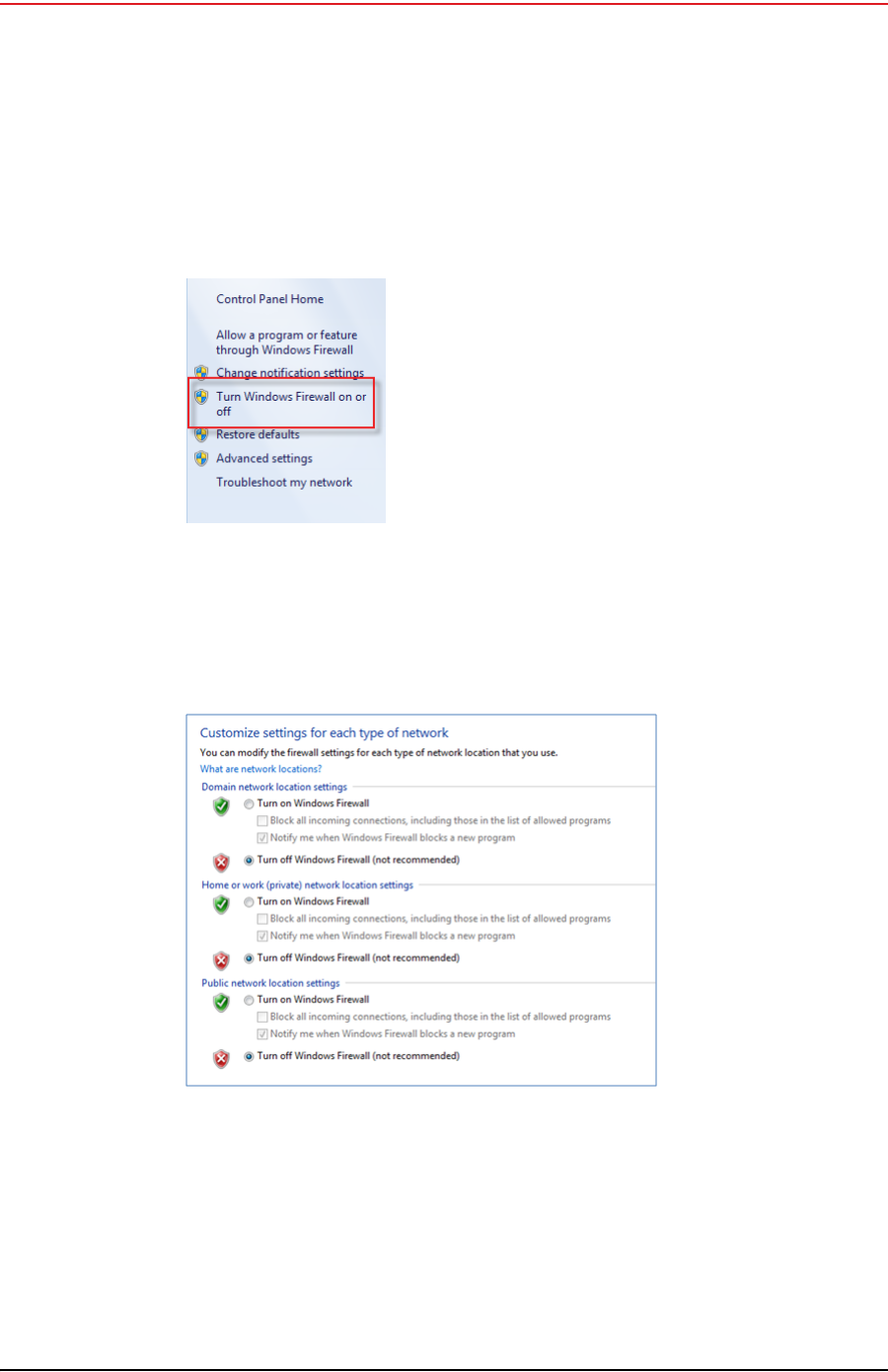
3.3 Turn off the Windows Firewall
This section describes how to turn off the Windows firewall.
To turn off the Windows firewall:
→Windows 7 computer → Start →Control Panel
1Click one of the following:
Figure 3–13 Weighted Base (70-0070)
Draft
R00.e RT System 2 v2.0.0 Deployment Guide 37
© 2010-2012 Wireless Seismic, Inc. All rights reserved.
3. Backhaul
Turn off the Windows Firewall
●Category View – Windows Firewall
●Icon View – System and Security → Windows Firewall
2Click Turn Windows Firewall on or off:
3Select Turn off Windows Firewall for all networks:
4Click OK.
Figure 3–14 Windows
Firewall On or Off
Figure 3–15 Windows Firewall Off

Draft
38 RT System 2 v2.0.0 Deployment Guide R00.e
© 2010-2012 Wireless Seismic, Inc. All rights reserved.
3. Backhaul
Configure the Radios
3.4 Configure the Radios
The FMQuadro™ Web Interface is used to configure the radio channels. The radio
licenses are pre-configured by Wireless Seismic, Inc. This section describes how to
connect the radios to a computer and configure them.
Check the radios before connecting them to any switch.
3.4.1 Create a Private Network
Create a private network between the computer and the Fluidmesh radio.
1Prerequisites:
●Windows computer
●Browser with Adobe Flash
●AC Power
●PoE Injector
●Two Ethernet Cables
2Power on the computer.
3Connect the components (see Figure 3–16 Fluidmesh Radio Private Network on
page 39):
●Plug the PoE injector into an AC outlet.
●Connect the computer to the PoE injector with an Ethernet cable.
●Connect the Fluidmesh radio to the PoE injector with an Ethernet cable. The
radio powers up.
►FM1100 – Connect to LAN 1
►FM3100 – There is only one connector
NOTE
The expected configuration in the RT System 2 system is as follows:
FM1100 = mesh point (remote backhaul)
FM3100 = mesh end (central backhaul)
NOTE
All Fluidmesh units are preconfigured from the factory with an IP
address of 192.168.0.10.
Wireless Seismic, Inc. reconfigures each Fluidmesh radios to have a
unique IP address, identifiable by the sticker placed on the radio.
If the radio is exposed to excessive static electricity, any post-factory-
configured IP address may reset to this factory-configured IP address.

Draft
R00.e RT System 2 v2.0.0 Deployment Guide 39
© 2010-2012 Wireless Seismic, Inc. All rights reserved.
3. Backhaul
Configure the Radios
4Verify that the radio powers up. The LED indicators have the following
meanings:
5Click the Windows Start icon.
6Select Control Panel. The Control Panel window opens.
CAUTION
Power up only one radio at a time. Never place two powered-up radios
next to each other. It is possible to damage the radio receivers if
multiple radios are powered up in close proximity.
Figure 3–16 Fluidmesh Radio Private Network
Table 3–6 Fluidmesh Radio LEDs
LED State Description
Power On / Green On whenever the radio has
power
LAN On / Green On whenever the radio has an
Ethernet connection
Signal Strength (1) On / Red Booting Core system
Signal Strength (2) On / Orange Booting wireless system
Signal Strength (3) On / Green Booting routing engine
Signal Strength (4) On / Green Booting unit configuration

Draft
40 RT System 2 v2.0.0 Deployment Guide R00.e
© 2010-2012 Wireless Seismic, Inc. All rights reserved.
3. Backhaul
Configure the Radios
7Select Network and Internet.
8Select Network and Sharing Center.
Figure 3–17 Control Panel, Network and Internet
Figure 3–18 Control Panel, Network and Sharing Center

Draft
R00.e RT System 2 v2.0.0 Deployment Guide 41
© 2010-2012 Wireless Seismic, Inc. All rights reserved.
3. Backhaul
Configure the Radios
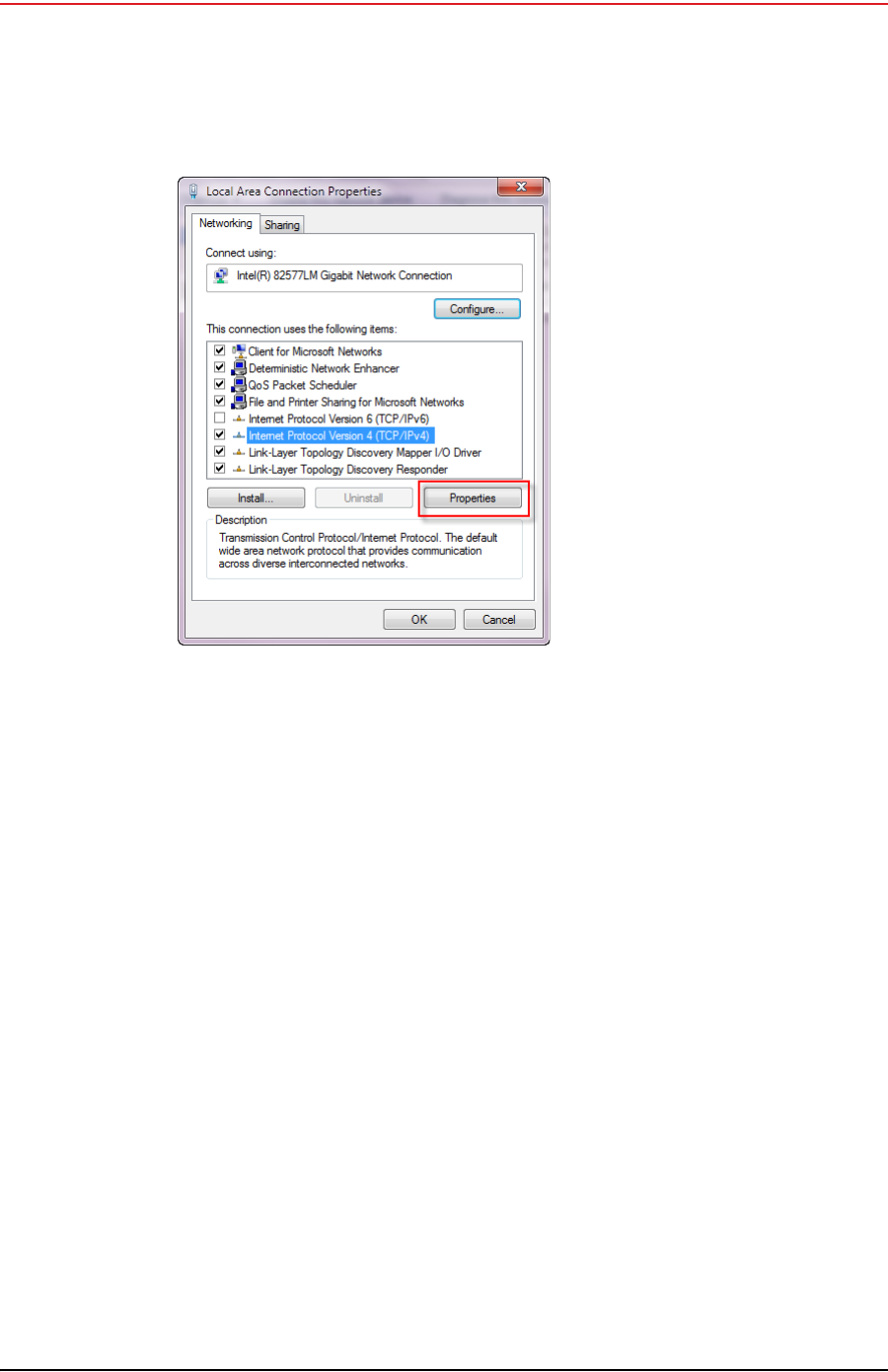
9In the left pane, select Change adapter settings.
10 Right-click Local Area Connection and select Properties. The Properties
window opens.
11 Select Internet Protocol Version 4 (TCP/IP v4) and click Properties.
Figure 3–19 Control Panel, Change Adapter Settings
Figure 3–20 Control Panel, LAN Properties
Draft
42 RT System 2 v2.0.0 Deployment Guide R00.e
© 2010-2012 Wireless Seismic, Inc. All rights reserved.
3. Backhaul
Configure the Radios
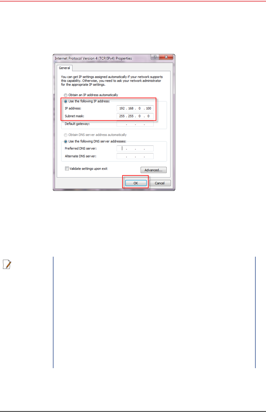
12 Select Use the following IP address.
Figure 3–21 Control Panel, Networking
Properties
Draft
R00.e RT System 2 v2.0.0 Deployment Guide 43
© 2010-2012 Wireless Seismic, Inc. All rights reserved.
3. Backhaul
Configure the Radios
13 Enter the following:
●IP address: 192.168.0.100 (this number does not have to be 100, just
something other than 10, and a number between 1 and 255)
●Netmask:255.255.255.0
14 Click OK.
Figure 3–22 Control Panel, IP Address
NOTE
If the radio already has an IP address, you will need to enter different
numbers. For example:
Radio IP address: 10.200.x.x
Computer IP address: 10.x.x.x
Subnet Mask: 255.0.0.0
You may need to disable and enable (right-click) the LAN connection if
it displays Network cable unplugged in the Network Connections
window.
If the radio gets reset, the default IP address is 192.168.0.10.
Draft
44 RT System 2 v2.0.0 Deployment Guide R00.e
© 2010-2012 Wireless Seismic, Inc. All rights reserved.
3. Backhaul
Configure the Radios
15 Click Close.
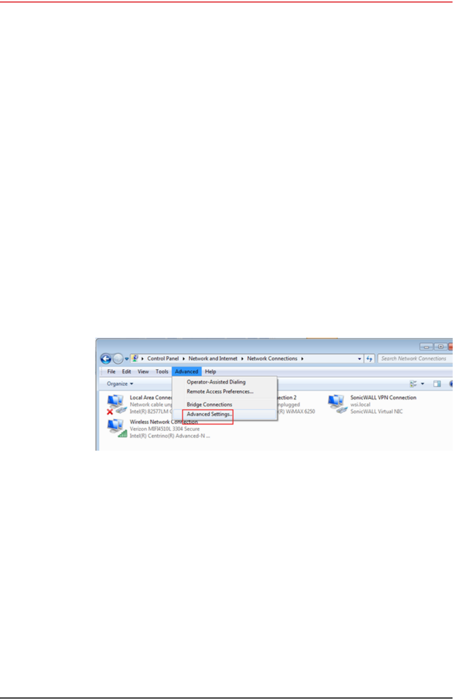
3.4.2 Setting NIC Priority
If you have more than one network interface card (NIC) in your computer, make
sure that the LAN card has the highest priority; the computer attempts to use the
NICs in the order listed.
To set NIC priority:
→Windows computer
1Click the Windows Start icon.
2Select Control Panel. The Control Panel window opens.
3Select Network and Internet.
4Select Network and Sharing Center.
5In the left pane, select Change adapter settings.
6In the toolbar, click Advanced, and then Advanced Settings.
7Select Local Area Connection and then click the up arrow repeatedly until
Local Area Connection is the first item.
Figure 3–23 Advanced Network Settings Menu

Draft
R00.e RT System 2 v2.0.0 Deployment Guide 45
© 2010-2012 Wireless Seismic, Inc. All rights reserved.
3. Backhaul
Configure the Radios
8Click OK.
3.4.3 Configure the Radio
Configure the radios by logging into the software located on the radio. FM1100s
are configured as mesh points, and FM3100s are configured as mesh ends.
To configure the radio:
→Windows computer
1On the computer, point a browser to the following URL:
http://192.168.0.10
Figure 3–24 LAN Hierarchy
TIP
Use Mozilla Firefox or Google Chrome. Internet Explorer does not
refresh correctly.

Draft
46 RT System 2 v2.0.0 Deployment Guide R00.e
© 2010-2012 Wireless Seismic, Inc. All rights reserved.
3. Backhaul
Configure the Radios
2Log in to the radio Web interface using the following:
●UserName: admin
●Password: admin
3The following figure shows the home window when mesh end is selected as
the Mode. The FM1100 configuration includes an additional left-pane option:
Power Over Ethernet. Click MeshWizard™.
NOTE
If the radio has an IP address other than the default IP address, you will
need to enter that number. For example, 10.101.0.22.
Figure 3–25 Radio Login Window

Draft
R00.e RT System 2 v2.0.0 Deployment Guide 47
© 2010-2012 Wireless Seismic, Inc. All rights reserved.
3. Backhaul
Configure the Radios
4Click I Agree to accept the licence agreement if prompted.
5Click Wizard.
6Select or enter the following:
●Mode
►FM1100 – Mesh Point
►FM3100 – Mesh End
●IP Address – Use next class A address available (10.2.0.1 - 10.2.0.255)
●Netmask – 255.0.0.0
●Default Gateway
►FM1100 – Not shown or available
Figure 3–26 Radio Home Window, Mesh End

Draft
48 RT System 2 v2.0.0 Deployment Guide R00.e
© 2010-2012 Wireless Seismic, Inc. All rights reserved.
3. Backhaul
Configure the Radios
►FM3100 – Leave blank
7Click Next.
8Select one of the following frequencies (see Figure 3–6 Channel Color Example
on page 30):
●Channel 1 = 5745 MHz (Yellow label)
●Channel 2 = 5180 MHz (Blue label)
●Channel 3 = 5505 MHz (Red label)
●Channel 4 = 5300 MHz (Green label)
9Click Next.
10 Verify the settings. Click Save&Reboot.
Figure 3–27 Fluidmesh MeshWizard Interface

Draft
R00.e RT System 2 v2.0.0 Deployment Guide 49
© 2010-2012 Wireless Seismic, Inc. All rights reserved.
3. Backhaul
Setting up the Backhaul Equipment
11 FM1100 only:
●Click poe pass-through in the ADVANCED SETTINGS area of the left
pane. This option allows the LAN 2 port on the radio to deliver passive PoE
to a second FM1100 on the mast using one short Ethernet cable.
●Select Enable for the Status.
●Click Apply.
3.4.4 Restore your Network Settings
When have finished configuring all of your radios, restore your network settings as
described in this section.
To restore network settings:
→Windows computer
1Click the Windows Start icon.
2Select Control Panel. The Control Panel window opens.
3Select Network and Internet.
4Select Network and Sharing Center.
5In the left pane, select Change adapter settings.
6Right-click Local Area Connection and select Properties. The Properties
window opens.
7Select Internet Protocol Version 4 (TCP/IP v4) and click Properties.
8Select Obtain IP address automatically.
9Click OK.
10 Click Close.
3.4.5 Using the Fluidmesh Interface to Scan
TBD
3.4.6 Using the Fluidmesh Interface to Ping
TBD
3.5 Setting up the Backhaul Equipment
Use the following procedure to erect and secure the mast

Draft
50 RT System 2 v2.0.0 Deployment Guide R00.e
© 2010-2012 Wireless Seismic, Inc. All rights reserved.
3. Backhaul
Setting up the Backhaul Equipment
To install the backhaul components and erect the mast:
1Prerequisites:
●Gather the components
●Screwdriver
●Hammer
2Refer to the deployment instructions to determine the location and compass
heading to the next back haul site closer to central.
3Use the compass to determine and mark that direction.
4Use the following considerations while positioning the base:
●Locate the base such that the three guy lines and the mast clear
obstructions during erection and while in operation.
●If the ground is sloped, position the base such that when the base is flush
to the ground, the bracket orientation allows the mast to remain
perpendicular to the ground as shown in the following figure:
●If the wind is blowing, the mast is more stable when the brackets are
perpendicular to the wind as shown in the following figure:
NOTE
There are many possible mast options; the following instructions are a
general guideline.
Figure 3–28 Mast on a Slope

Draft
R00.e RT System 2 v2.0.0 Deployment Guide 51
© 2010-2012 Wireless Seismic, Inc. All rights reserved.
3. Backhaul
Setting up the Backhaul Equipment
5Collect all of the mast components.
6Secure the base with at least 2 nails or if using a weighted mast, with cement
blocks.
7Insert the mast into the base collar, extend and secure each section of the
mast.
8Attach the guy lines to the collar on the mast, or make loops in the lines and
slip them over the mast.
9Align one guy line so that it extends in the opposite direction from the mast
while the mast is still on the ground.
10 Align the other two guy lines at 120 degrees (1/3 of a circle) from the first guy
line.
11 Hammer guy line stakes into ground and secure guy lines at the indicated
marks.
12 Attach the radio or radios at the top of the mast.
13 Uncoil an Ethernet cable, attach one end to a radio unit and the other end to
the LIU. Form a service loop (extra cable) by looping the Ethernet cable over
the top of the radio unit. If you are installing two radios on the mast, refer to
“Installing Two Radios on the Mast” on page 53 for cabling and configuration
instructions.
14 Ensure that all directional antennas, when raised, are pointed correctly. The
radio unit should be facing toward the recording truck.
15 While holding the free guy line, lift / walk the mast to a vertical position and
secure the line into the cleat.
16 Adjust all lines to bring the mast to a vertical position.
17 Ensure that each line is firmly seated in each cleat, loosely wrap lines around
mast and secure at the large cleat on the base.
Figure 3–29 Base and Wind Orientation

Draft
52 RT System 2 v2.0.0 Deployment Guide R00.e
© 2010-2012 Wireless Seismic, Inc. All rights reserved.
3. Backhaul
Setting up the Backhaul Equipment
18 Check to make sure that the antennas are aimed properly.
Figure 3–30 Securing Lines to Large Cleat
Figure 3–31 Backhaul Antenna Erected

Draft
R00.e RT System 2 v2.0.0 Deployment Guide 53
© 2010-2012 Wireless Seismic, Inc. All rights reserved.
3. Backhaul
Installing Two Radios on the Mast
3.6 Installing Two Radios on the Mast
When you are installing a remote backhaul, there can be two radios on the mast
as shown in the following figure:
To install two radios on the mast:
1Prerequisites:
●TBD
●The radios are configured to allow the PoE option (see step 11 on page 49).
●The radios are BOTH configured as mesh POINTS (see step 6 on page 47).
Figure 3–32 Two-Radio Installation

Draft
54 RT System 2 v2.0.0 Deployment Guide R00.e
© 2010-2012 Wireless Seismic, Inc. All rights reserved.
3. Backhaul
Removing the Backhaul Equipment
2Attach two radios to the mast. Refer to the deployment instructions for the
location at which to aim the radio. One should point towards the recording
truck (uplink), and the other should point towards the next remote backhaul
location (downlink).
3Connect the two radios with a short Ethernet cable: Radio1/LAN 2 to Radio 2/
LAN 1.
4Connect Radio 1/LAN 1 to the LIU.
3.7 Removing the Backhaul Equipment
TBD
3.8 Use Cases or Example Deployments
This section shows a few example deployments.

Draft
R00.e RT System 2 v2.0.0 Deployment Guide 55
© 2010-2012 Wireless Seismic, Inc. All rights reserved.
3. Backhaul
Use Cases or Example Deployments
Figure 3–33 Single Backhaul

Draft
56 RT System 2 v2.0.0 Deployment Guide R00.e
© 2010-2012 Wireless Seismic, Inc. All rights reserved.
3. Backhaul
Use Cases or Example Deployments
Figure 3–34 Dual Backhaul, Two Root Nodes
Draft
R00.e RT System 2 v2.0.0 Deployment Guide 57
© 2010-2012 Wireless Seismic, Inc. All rights reserved.
3. Backhaul
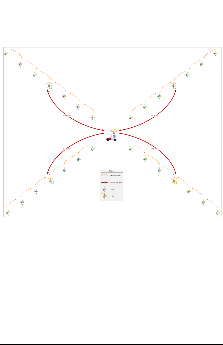
Use Cases or Example Deployments
Figure 3–35 Single Backhaul, Star Configuration