YAMAHA MOTOR POWERED JW9-85560-00 BASE ASSY User Manual
YAMAHA MOTOR POWERED PRODUCTS CO., LTD. BASE ASSY Users Manual
User manual

䇭
1. Introduction of the product
These devices make it possible to efficiently manage and maintain numerous YDRE's in a single golf course.
䇭
2. Parts and descriptions
䇭(1) Parent device
䇭(2) Relay device
LAN cable IN
䌁䌃 adapter
Radio antenna
Body
䌌䌅䌄
䌁䌃 adapter
䌄䌃 Jack
bracket for wall surface installation
NSYPFPLM
Transmitter
(The general term Parent device in the text means a BASE ASSY.)
(The general term Relay device in the text means a TRANSMITTING UNIT.)
䇭
3. Installation
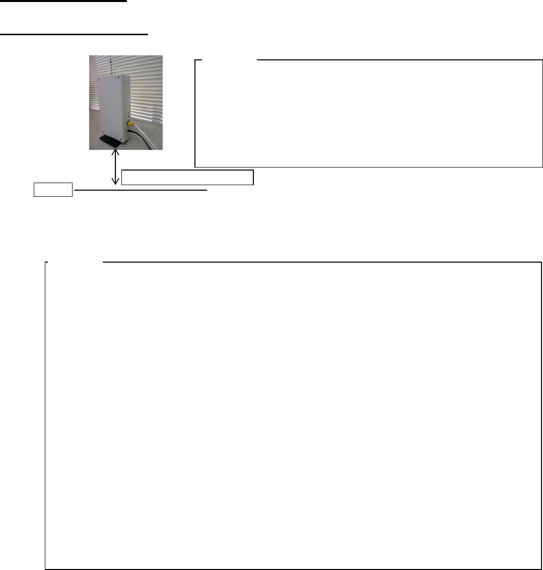
䇭(1) Parent device
Install this device indoors, near the window, and at 150cm or higher from the floor.
䇭䊶㪠㫅㫊㫋㪸㫃㫃㩷㫋㪿㫀㫊㩷㫇㪸㫉㪼㫅㫋㩷㪻㪼㫍㫀㪺㪼㩷㪠㫅㪻㫆㫆㫉㫊㪃㩷㫅㪼㪼㫉㩷㪸㩷㫎㫀㫅㪻㫆㫎㪃㩷㪸㫋㩷㪸㩷㪿㪼㫀㪾㪿㫋㩷㫆㪽
㩷㩷㩷㪸㫋㩷㫃㪼㪸㫊㫋㩷㪈㪌㪇㪺㫄㩷㪽㫉㫆㫄㩷㫋㪿㪼㩷㪽㫃㫆㫆㫉㪅
䇭䊶Install this device as far away from the metal object as possible,
䇭䇭㫊uch as metal blinds, glass with steel wires, etc.
䇭䊶Install this device as far away from 100BASE-T or higher devices
as possible.
䇭䊶Install a lightening guard on the AC outlet.
㩷㩷䊶㪞㪝㪚㪠㩷㫆㫌㫋㫃㪼㫋㩷㫆㫅㫃㫐㪅
䇭(2) Relay device
Install the relay device on the wall near the entrance to the cart barn, and at least 150cm above
the ground.
䇭䊶Select a location not subject to direct wind or rain which can support the weight of the relay
㩷㩷㩷㩷㪻㪼㫍㫀㪺㪼㪅
䇭䊶If the AC power source for the relay device is located outside, use only GFCI and UL50
㩷㩷㩷㩷㪺㫆㫄㫇㫃㫀㪸㫅㫋㩷㫆㫌㫋㫃㪼㫋㪅
䇭䊶Do not allow the AC cord to contact the ground. Secure It on the wall using molding.
䇭䊶If the relay device is to be mounted on a steel wall or a wall with steel reinforcement, place It
as far away from the steel reinforcement as possible.
䇭䊶Keep the relay device away from 100BASE-T or higher devices as possible.
䊶Installation condition
Mounting on wallsType of wall: Wood
Screw size: ij6×20mm or larger
Product weight: 6.3kg
If the product is to be mounted on walls other than wooden walls, use the appropriate mounting
screws such as the anchor bolts, etc.(Example: Fisher plug S8 and ij6 ×60mm screws䋩
Other requirements and cautions 䇭
A
lways have an experienced contractor mount this product.
Always have this product mounted at four points.
Don’t store anything inside the product.
If the product is to be mounted on walls other than wooden walls, use the appropriate mounting
screws such as the anchor bolts, etc.
Even if the wall is made of wood, it may not guarantee sufficient strength depending on
the thickness of the wood.
Make sure that you get sufficient mounting strength before actually mounting this device.
Floor
Height䋺 150cm or higher
NOTICE
NOTICE

䇭Wall mount bracket
䇭Relay device installed near the entrance to the cart barn
䇭䇭䇭㶎When replacing the fuses inside the relay device:
䇭䇭䇭䇭䇭䊶 Disconnect the AC plug from the outlet.
䇭䇭䇭䇭䇭䊶 Using the key provided , unlock and open the lid.
䇭䇭䇭䇭䇭䊶 Replace the bad fuse with the specified fuse (RetelFuse: 0312. 200MXP).
䇭䇭䇭䇭䇭䊶 Confirm that the fuse is securely placed in the metal holder.
䇭䇭䇭䇭䇭䊶 Replace and lock the lid.
WARNING
䊶To reduce the danger of fire, use only the electric circuit rated for 5 amps. or higher
equipped with a circuit breaker.
䊶Make sure that none of the AC cords or the LAN cables interfere with pedestrian traffic
䇭or other equipment.
䊶Secure wiring on the walls with molding.
䊶Do not place wiring on the ground.
䊶Do not place heaving items on the wiring.
䊶Do not install wiring where it may be subjected to grease.
WARNING 䊶Always visually, and by touch, confirm that the AC plug and all system devices are
in good working order.
䊶Do not use this Vehicle Management System under the following conditions:
-If the AC plug is loose, not secure, or good electric contact is not established.
-If the AC plug or the system devices feel hotter than usual.
-The AC plug is bent, corroded, blackened, or showing blue.
-The wiring of the AC plug or the LAN shows cuts, wear, breakage, or exposure of
the conductor.
NOTICE Do not disassemble the transmitter or the AC adapter.
Only an authorized Yamaha dealer is authorized to perform maintenance on the
internal devices.
Relay device
AC outlet for outdoor use

FCC WARNING
Changes or modifications not expressly approved by the party responsible for compliance could
void the user's authority to operate the equipment.
Note. This equipment has been tested and found to comply with the limits for a Class A digital
device , pursuant to part 15 of the FCC Rules. These limits are designed to provide reasonable
protection against harmful interference when the equipment Is oparated in a commercial
environment. This equipment generates, uses, and can radiate radio frequency energy and, if not
installed and used in accordance with the instruction manual, may cause harmful interference to
radio communications, Operation of this equipment in a residential area is likely to cause harmful
interference in which case the user will be required to correct the interference at his own expence.
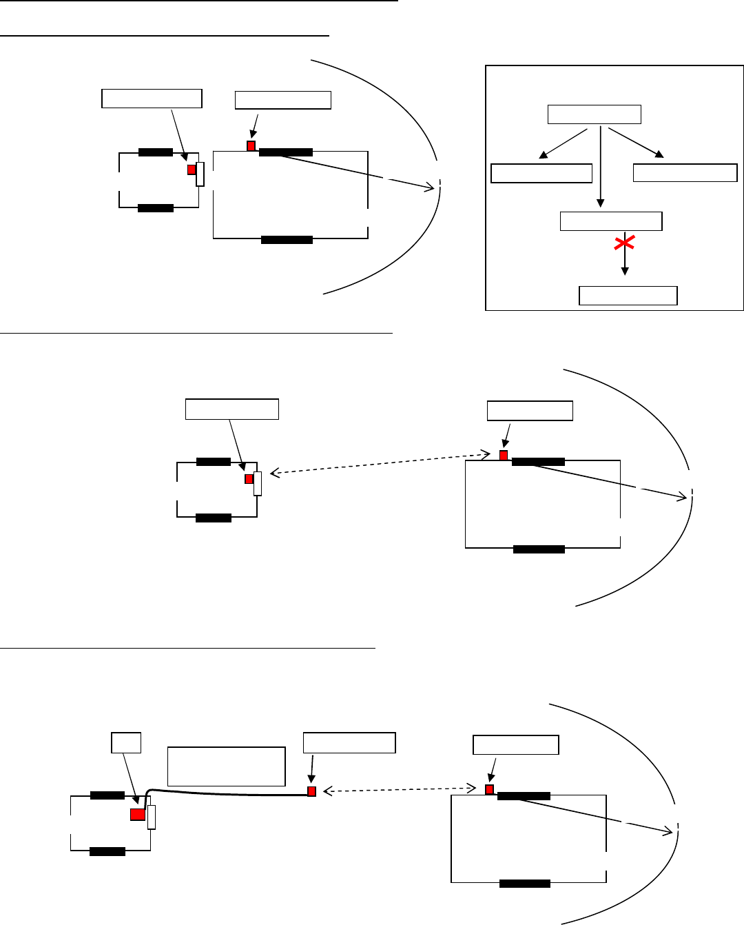
䇭(3) Sample installation on the club house and the cart barn
䇭䇭1. The cart barn stands next to the club house.
Can communicate with the vehicles inside the cart barn and within 100m from the relay device.
䇭䇭2. The cart barn is somewhat away from the club house.
Communication between the parent and the relay devices can be established up to about 100m
straight distance.
䇭䇭3. The cart barn is beyond 150m from the club house.
Install a parent device housed inside the relay device box at about 100m straight distance from
the relay device.
㶎It would require installation of the LAN cable from the club house and the AC power supply to
the parent device.
㪚㫃㫌㪹㩷㪿㫆㫌㫊㪼
㪚㪸㫉㫋㩷㪹㪸㫉㫅
⓹
㪜㫅㫋㫉㪸㫅㪺㪼
㪜㫅㫋㫉㪸㫅㪺㪼
㪜㫅㫋㫉㪸㫅㪺㪼
Parent device Rela
y
device
㪘㪹㫆㫌㫋㩷㪈㪇㪇㫄
㪺㫃㫌㪹㩷㪿㫆㫌㫊㪼
㪚㪸㫉㫋㩷㪹㪸㫉㫅
㪮㫀㫅㪻㫆㫎
㪜㫅㫋㫉㪸㫅㪺㪼
㪜㫅㫋㫉㪸㫅㪺㪼
㪜㫅㫋㫉㪸㫅㪺㪼
㪧㪸㫉㪼㫅㫋㩷㪻㪼㫍㫀㪺㪼 㪩㪼㫃㪸㫐㩷㪻㪼㫍㫀㪺㪼
㪘㪹㫆㫌㫋㩷㪈㪇㪇㫄
㶎㪬㫇㩷㫋㫆㩷㪊㩷㫉㪼㫃㪸㫐㩷㪻㪼㫍㫀㪺㪼㫊㩷㫄㪸㫐㩷㪹㪼
㪺㫆㫅㫅㪼㪺㫋㪼㪻㩷㫋㫆㩷㪸㩷㫊㫀㫅㪾㫃㪼㩷㫇㪸㫉㪼㫅㫋㩷㪻㪼㫍㫀㪺㪼㪅
㪫㫎㫆㩷㫆㫉㩷㫄㫆㫉㪼㩷㫉㪼㫃㪸㫐
㪻㪼㫍㫀㪺㪼㫊㩷㪺㪸㫅㩾㫋㩷㪹㪼
㪺㫆㫅㫅㪼㪺㫋㪼㪻㪅
㪧㪸㫉㪼㫅㫋㩷㪻㪼㫍㫀㪺㪼
㪩㪼㫃㪸㫐㩷㪻㪼㫍㫀㪺㪼㩷㪈
㪩㪼㫃㪸㫐㩷㪻㪼㫍㫀㪺㪼㩷㪉
㪩㪼㫃㪸㫐㩷㪻㪼㫍㫀㪺㪼㩷㪊
㪩㪼㫃㪸㫐㩷㪻㪼㫍㫀㪺㪼㩷㪊
㪚㫃㫌㪹㩷㪿㫆㫌㫊㪼
㪚㪸㫉㫋㩷㪹㪸㫉㫅
㪮㫀㫅㪻㫆㫎
㩷㪜㫅㫋㫉㪸㫅㪺㪼
㪜㫅㫋㫉㪸㫅㪺㪼
㪜㫅㫋㫉㪸㫅㪺㪼
㪧㪚 㪩㪼㫃㪸㫐㩷㪻㪼㫍㫀㪺㪼
㪘㪹㫆㫌㫋㩷㪈㪇㪇㫄
㪧㪸㫉㪼㫅㫋㩷㪻㪼㫍㫀㪺㪼
㪘㪹㫆㫌㫋㩷㪈㪇㪇㫄
㫊㫋㫉㪸㫀㪾㪿㫋㩷㪻㫀㫊㫋㪸㫅㪺㪼
㪘㪹㫆㫌㫋㩷㪈㪇㪇㫄
㫊㫋㫉㪸㫀㪾㪿㫋㩷㪻㫀㫊㫋㪸㫅㪺㪼
㪣㪘㪥㩷㪺㪸㪹㫃㪼
㪘㪚㩷㫇㫆㫎㪼㫉㩷㫊㫌㫇㫇㫃㫐
䇭
4. Operation
䇭䇭(1) Setting up the Vehicle Management PC
䇭䇭䇭䇭Refer to the separate "Vehicle Management Software Installation Manual".
䇭䇭(2) Registering the vehicles and the relay devices
䇭䇭1. Temporarily place the parent and the relay devices at the possible locations.
䇭䇭2. Install the child devices on all the vehicles. Bring them into the cart barn, and then turn OFF
㩷㩷㩷㩷㩷㩷㩷㫋㪿㪼㩷㪫㪦㪮㩷㪪㪮㪅
䇭䇭䇭䇭㶎Write down, in advance, the vehicle control numbers and the ID's of the child devices.
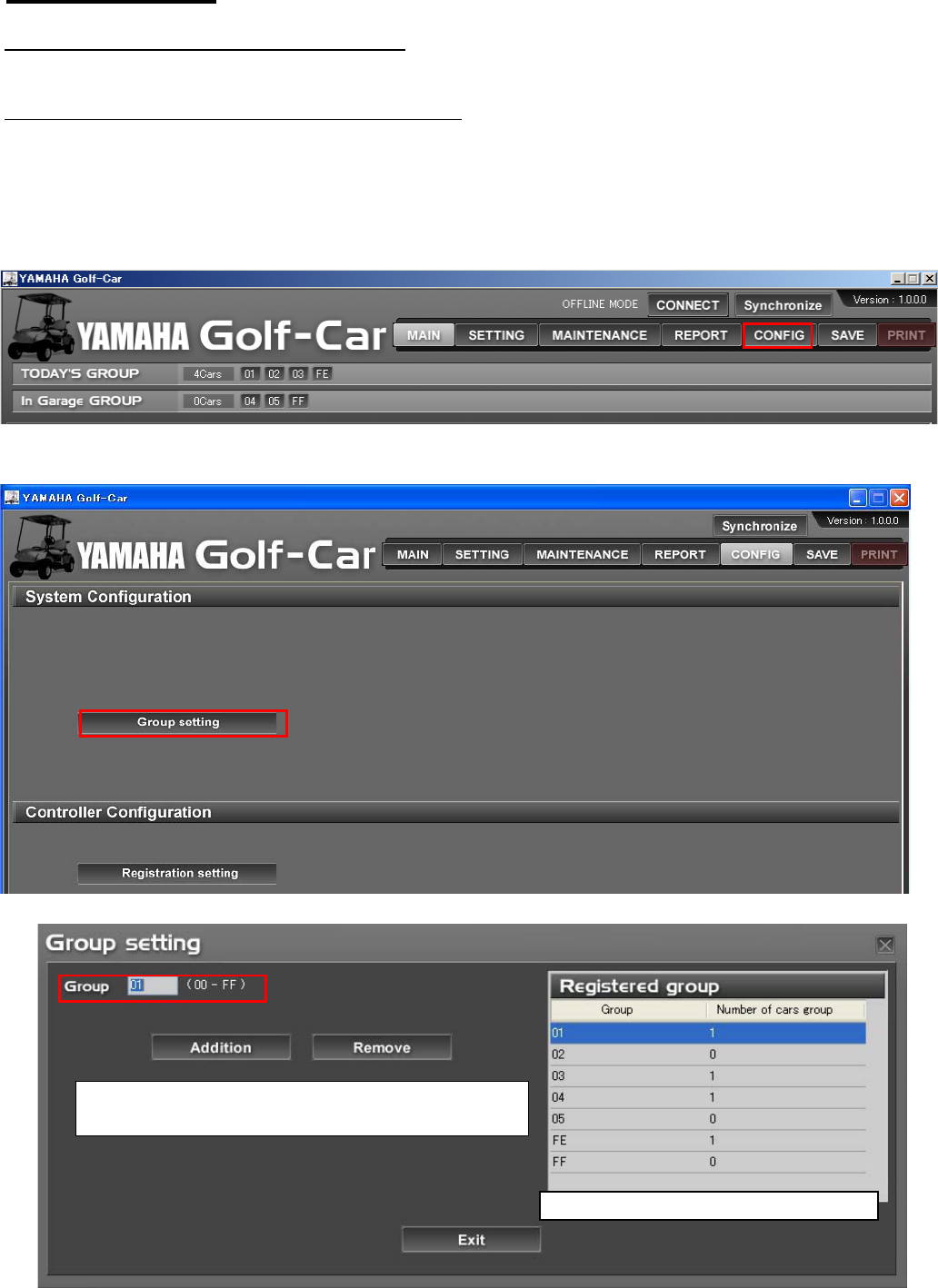
䇭䇭3. Run the vehicle management software, and click the "CONFIG" button.
䇭䇭4. First set up the vehicle group.
䇭䇭䇭Click the "Group setting" button.
䇭䇭5. Set up the number of groups and the group number.
㪟㫀㪄㫃㫀㪾㪿㫋㩷㫋㪿㪼㩷㪾㫉㫆㫌㫇㩷㫅㫌㫄㪹㪼㫉㪃㩷㪸㫅㪻㩷㫋㪿㪼㫅㩷㪺㫃㫀㪺㫂㩷㩹㪘㪻㪻㫀㫋㫀㫆㫅㩹
㪹㫌㫋㫋㫆㫅㩷㫋㫆㩷㪺㫆㫅㪽㫀㫉㫄㩷㫀㫋㪅
㪫㪿㪼㩷㪻㪸㫋㪸㩷㫀㫅㫇㫌㫋㩷㫀㫊㩷㪻㫀㫊㫇㫃㪸㫐㪼㪻㩷㫀㫅㩷㫋㪿㪼㩷㫃㫀㫊㫋㪅
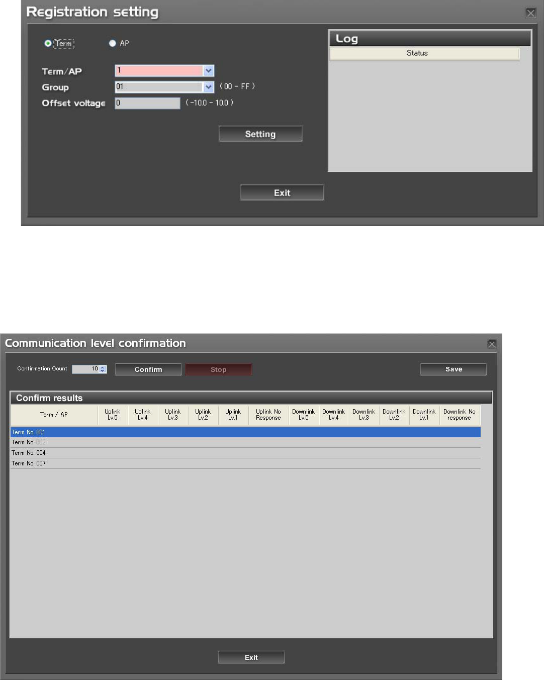
䇭䇭6. Register the vehicles.
䇭䇭䇭䊶Select the child device ID and the group, click the "Setting" button, and then turn the TOW SW ON.
䇭䇭䇭䇭(Repeat this operation for every one of the vehicles.)
䇭䇭䇭䊶In the same way, register the relay device (AP) and connect the AC plug.
䇭䇭7. Confirm the results of registration.
䇭䇭䇭Return to the "MIAN" screen, verify that all the vehicles are located "In Cart Barn", and then check
the level of signal reception of each cart.
䇭䇭䇭㶎If the signal reception level is low, move the relay device to achieve the signal reception
level of 3 or higher.
䇭䇭8. Confirm the level of the signal reception.
䇭䇭䇭Go to the "Communication level confirmation" screen and confirm the level of each cart.
䇭䇭8. End
䇭䇭(3) How to use the Vehicle Management software
䇭Before start of the day
䇭䇭䇭1. Pick up the vehicles to be used for the day in the "SETTTING" screen.
䇭䇭䇭2. Confirm on the "MAIN" screen, the status of the battery, abnormality reported by the diagnosis system,
㩷㩷㩷㩷㩷㩷㩷㩷㩷㪸㫅㪻㩷㪽㫆㫉㩷㪻㫀㫊㫇㫃㪸㫐㩷㫆㪽㩷㫋㪿㪼㩷㫇㪼㫉㫀㫆㪻㫀㪺㩷㫀㫅㫊㫇㪼㪺㫋㫀㫆㫅㪅
䇭䇭䇭䇭䇭㶎If the diagnosis reports an abnormality or the system displays the periodic inspection, go to the
"MAINTENANCE" screen and confirm the messages, and then perform necessary
䇭䇭䇭䇭䇭䇭 maintenance to the vehicle.
Start of the day
䇭䇭䇭3. Run vehicle rental operations.
䇭䇭䇭䇭䊶Once the player is out on the course, the system moves the vehicle to the "On course" zone.
䇭䇭䇭䇭䊶On completion of a round, when the vehicle approaches the club house (in the communication range),
the system moves this vehicle to the "In Cart Barn" zone.
Before end of the day
䇭䇭䇭4. Confirm on the "MAIN" screen that all the vehicles have returned to the "In Cart Barn" zone.
䇭䇭䇭5. Check the charge status, diagnosis results, and the display for periodic inspection on each vehicle
which was used today.
䇭䇭䇭䇭䇭㶎If the diagnosis reports an abnormality or the system displays the periodic inspection, go to the
"MAINTENANCE" screen and confirm the messages, and then perform necessary
䇭䇭䇭䇭䇭䇭maintenance to the vehicle.
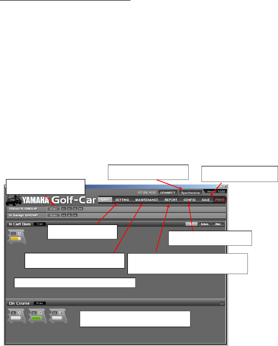
䇭(1) Main screen
This is the portal screen for the day-to-day vehicle management.
㪜㫊㫋㪸㪹㫃㫀㫊㪿㩷㪺㫆㫄㫄㫌㫅㫀㪺㪸㫋㫀㫆㫅㩷㫎㫀㫋㪿
㪰㪸㫄㪸㪿㪸㩷㪪㪼㫉㫍㫀㪺㪼㩷㪧㪚㪅 㪤㪸㫂㪼㩷㪸㩷㪹㪸㪺㫂㪄㫌㫇㩷㪽㫆㫉㩷㫋㪿㪼㩷㫍㪼㪿㫀㪺㫃㪼
㪻㪸㫋㪸㪃㩷㫉㪼㫇㪸㫀㫉㩷㪿㫀㫊㫋㫆㫉㫐㪃㩷㪼㫋㪺㪅
㪭㪼㪿㫀㪺㫃㪼㩷㪾㫉㫆㫌㫇㫊㩷㫎㪿㫀㪺㪿㩷㪸㫉㪼㩷㫀㫅
㫊㪼㫉㫍㫀㪺㪼㩷㪽㫆㫉㩷㫋㪿㫀㫊㩷㪻㪸㫐㪅
㪪㫇㪼㪺㫀㪽㫐㩷㫋㪿㪼㩷㫍㪼㪿㫀㪺㫃㪼㫊㩷㫋㫆㩷㪹㪼
㫌㫊㪼㪻㩷㪽㫆㫉㩷㫋㪿㪼㩷㪻㪸㫐㪅 㪩㪼㪾㫀㫊㫋㪼㫉㩷㫋㪿㪼㩷㪺㫆㫌㫉㫊㪼㩷㫀㫅㪽㫆㫉㫄㪸㫋㫀㫆㫅㪃
㫍㪼㪿㫀㪺㫃㪼㫊㪃㩷㫉㪼㫃㪸㫐㩷㪻㪼㫍㫀㪺㪼㪃㩷㪼㫋㪺㪅
㪛㫀㫊㫇㫃㪸㫐㫊㩷㫋㪿㪼㩷㫊㫋㪸㫋㫌㫊㩷㫆㪽㩷㪼㪸㪺㪿㩷㫍㪼㪿㫀㪺㫃㪼㩷㪸㫃㫆㫅㪾
㫎㫀㫋㪿㩷㫋㪿㪼㩷㫄㪸㫀㫅㫋㪼㫅㪸㫅㪺㪼㩷㫊㫋㪸㫋㫌㫊㪅
㪛㫀㫊㫇㫃㪸㫐㫊㩷㫋㪿㪼㩷㫆㫇㪼㫉㪸㫋㫀㫆㫅㩷㪿㫀㫊㫋㫆㫉㫐㩷㪸㫅㪻㩷㫋㪿㪼
㫄㪸㫀㫅㫋㪼㫅㪸㫅㪺㪼㩷㪿㫀㫊㫋㫆㫉㫐㩷㫆㪽㩷㪸㫃㫃㩷㫋㪿㪼㩷㫍㪼㪿㫀㪺㫃㪼㫊㪃㩷㪹㫐㩷㫍㪼㪿㫀㪺㫃㪼
㪸㫅㪻㩷㪹㫐㩷㪾㫉㫆㫌㫇㪅
㪛㫀㫊㫇㫃㪸㫐㫊㩷㫋㪿㪼㩷㫊㫋㪸㫋㫌㫊㩷㫆㪽㩷㫋㪿㪼㩷㫍㪼㪿㫀㪺㫃㪼㩷㫀㫅㩷㫋㪿㪼㩷㪺㪸㫉㫋㩷㪹㪸㫉㫅㪅
㪛㫀㫊㫇㫃㪸㫐㫊㩷㫋㪿㪼㩷㫍㪼㪿㫀㪺㫃㪼㫊㩷㫃㫆㪺㪸㫋㪼㪻㩷㫆㫌㫋㫊㫀㪻㪼㩷㫋㪿㪼㩷㪺㪸㫉㫋
㪹㪸㫉㫅㩷㩿㫆㫌㫋㫊㫀㪻㪼㩷㫋㪿㪼㩷㪺㫆㫄㫄㫌㫅㫀㪺㪸㫋㫀㫆㫅㩷㫉㪸㫅㪾㪼㪀㪅

䇭(2) "SETTING" screen
䇭䇭Select the groups of the vehicles which are to be used for the day (drag and drop the groups from
"In Garage GROUP" to "TODAY'S GROUP").
䇭䇭䇭㶎The groups can be sorted by the travel distance, service hours, or by the battery discharge level.
䇭(3)"MAINTENANCE" screen
䇭䇭This screen offers the vehicle maintenance status in details.
㪞㫉㫆㫌㫇㩷㫅㫌㫄㪹㪼㫉
㪥㫆㪅㩷㫆㪽㩷㫍㪼㪿㫀㪺㫃㪼㫊㩷㫎㫀㫋㪿㫀㫅㩷㫋㪿㪸㫋㩷㪾㫉㫆㫌㫇
㪘㫍㪼㫉㪸㪾㪼㩷㫋㫉㪸㫍㪼㫃㩷㪻㫀㫊㫋㪸㫅㪺㪼㩷㪽㫆㫉㩷㫋㪿㪼㩷㪾㫉㫆㫌㫇
㪘㫍㪼㫉㪸㪾㪼㩷㫊㪼㫉㫍㫀㪺㪼㩷㪿㫆㫌㫉㫊㩷㪽㫆㫉㩷㫋㪿㪼㩷㪾㫉㫆㫌㫇
㪘㫍㪼㫉㪸㪾㪼㩷㪹㪸㫋㫋㪼㫉㫐㩷㪻㫀㫊㪺㪿㪸㫉㪾㪼㩷㫃㪼㫍㪼㫃㩷㪽㫆㫉㩷㫋㪿㪼㩷㪾㫉㫆㫌㫇
㪛㫀㫊㫇㫃㪸㫐㫊㩷㫊㫐㫊㫋㪼㫄㩷㪽㪸㫌㫃㫋㫊㩷㪻㪼㫋㪼㫉㫄㫀㫅㪼㪻㩷㪹㫐
㫋㪿㪼㩷㫍㪼㪿㫀㪺㫃㪼㩷㪺㫆㫅㫋㫉㫆㫃㫃㪼㫉㩾㫊㩷㫊㪼㫃㪽㪄㪻㫀㪸㪾㫅㫆㫊㫀㫊㪅
㪚㫃㫀㪺㫂
㫋㪿㪼㩷㩹㪫㫉㫆㫌㪹㫃㪼㩷㫊㪿㫆㫆㫋㩹㩷㪹㫌㫋㫋㫆㫅㩷㫋㫆㩷㪻㫀㫊㫇㫃㪸㫐
㫋㪿㪼㩷㫉㪼
㫇
㪸㫀㫉㩷
㪾
㫌㫀㪻㪼㪅
㪛㫀㫊㫇㫃㪸㫐㫊㩷㫋㪿㪼㩷㫄㪸㫀㫅㫋㪼㫅㪸㫅㪺㪼㩷㪿㫀㫊㫋㫆㫉㫐㪅㩷㩷㪚㫃㫀㪺㫂
㫋㪿㪼㩷㩹㪘㪻㪻㫀㫋㫀㫆㫅㩹㩷㪹㫌㫋㫋㫆㫅㩷㫋㫆㩷㫄㪸㫅㫌㪸㫃㫃㫐㩷㪸㪻㪻
㪻㪸㫋㪸㪅
㪛㫀㫊㫇㫃㪸㫐㫊㩷㫋㪿㪼㩷㫇㪼㫉㫀㫆㪻㫀㪺㩷㫄㪸㫀㫅㫋㪼㫅㪸㫅㪺㪼㩷㫀㫋㪼㫄㫊
㪺㫆㫉㫉㪼㫊㫇㫆㫅㪻㫀㫅㪾㩷㫋㫆㩷㫋㪿㪼㩷㫍㪼㪿㫀㪺㫃㪼㩾㫊㩷㫌㫊㪸㪾㪼
㫊㫋㪸㫋㫌㫊㪅
㪮㪿㪼㫅㩷㫐㫆㫌㩷㪿㪸㫍㪼㩷㪺㫆㫄㫇㫃㪼㫋㪼㪻㩷㫋㪿㪼
㫄㪸㫀㫅㫋㪼㫅㪸㫅㪺㪼㪃㩷㪺㫃㫀㪺㫂㩷㫋㪿㪼㩷㩹㪚㪟㪜㪚㪢㩹㩷㪹㫌㫋㫋㫆㫅㪅
㪚㫃㫀㪺㫂㩷㫋㪿㫀㫊㩷㪹㫌㫋㫋㫆㫅㩷㫀㪽㩷㫐㫆㫌㩷㫅㪼㪼㪻㩷㫋㫆
㫉㪼㫈㫌㪼㫊㫋㩷㪸㩷㫉㪼㫇㪸㫀㫉㩷㪽㫉㫆㫄㩷㪰㪸㫄㪸㪿㪸
㪪㪼㫉㫍㫀㪺㪼㪅
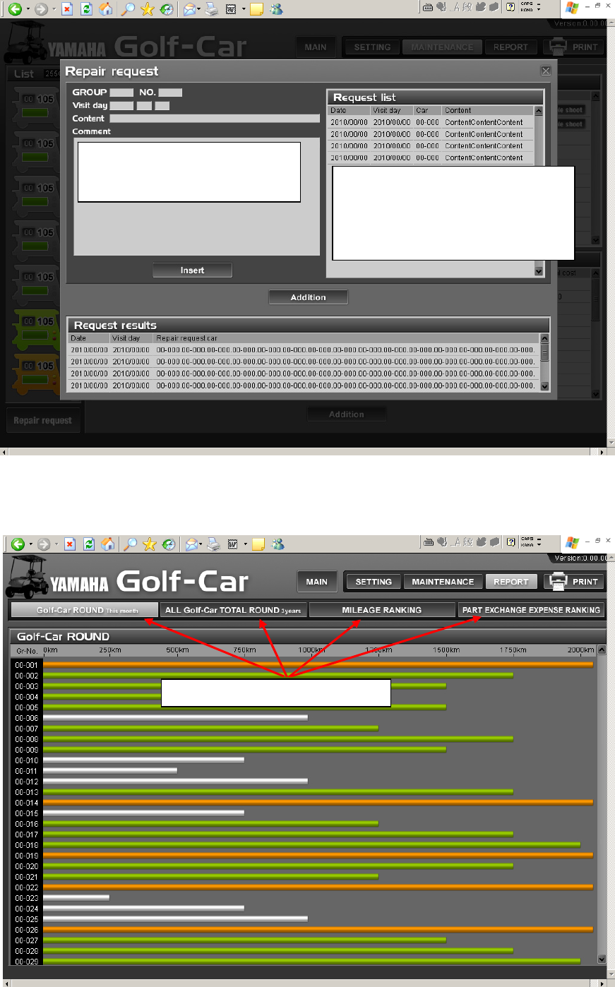
䇭(4) "Repair request" screen
䇭(5) "Report" screen
䇭䇭䇭This screen displays the rounds traveled by vehicle for the month, total rounds traveled by all vehicles in
the past three years, and the travel distance ranking, etc. in a list.
㪜㫅㫋㪼㫉㩷㫋㪿㪼㩷㫍㪼㪿㫀㪺㫃㪼㩷㫅㫌㫄㪹㪼㫉㪃㩷㪻㪼㫊㫀㫉㪼㪻
㪻㪸㫋㪼㩷㫆㪽㩷㫍㫀㫊㫀㫋㪃㩷㪸㫅㪻㩷㫋㪿㪼㩷㪻㪼㫊㪺㫉㫀㫇㫋㫀㫆㫅
㫆㪽㩷㫋㪿㪼㩷㫉㪼㫇㪸㫀㫉㪅 㪫㫉㪸㫅㫊㫄㫀㫊㫊㫀㫆㫅㩷㪺㫌㪼㩷㪽㫆㫉㩷㫋㪿㪼㩷㫉㪼㫇㪸㫀㫉
㫉㪼㫈㫌㪼㫊㫋㫊㪅㩷㩷㪮㪿㪼㫅㩷㫋㪿㪼㩷㫉㪼㫈㫌㪼㫊㫋㩷㪿㪸㫊
㪹㪼㪼㫅㩷㫋㫉㪸㫅㫊㫄㫀㫋㫋㪼㪻㩷㫋㫆㩷㪰㪸㫄㪸㪿㪸㩷㪪㪼㫉㫍㫀㪺㪼㪃
㫀㫋㩷㫄㫆㫍㪼㫊㩷㫋㫆㩷㫋㪿㪼㩷㩹㪩㪼㫈㫌㪼㫊㫋㩷㫉㪼㫊㫌㫃㫋㫊㩹
㪹㪼㫃㫆㫎㪅
㪛㫀㫊㫇㫃㪸㫐㩷㪺㪿㪸㫅㪾㪼㫊㩷㪹㫐㩷㫋㪿㪼㩷㪹㫌㫋㫋㫆㫅㪅

䇭
5. Equipment specifications
1. Parent device
In service䋺CH1 (default)
Item Specifications Remarks
Product model type JW9-85560-00
External 220 X 110 X 44mm
Product weight About 480g
Region USA
Operating
tem
p
eratures -10䌾60㷄
Operating humidity 85%Rh or lower No formation of dew
Rated Voltage DC 12V Voltage tolerance 㫧5%
Rated Current 0.5A
Max. power
consumption 7W or less Input of the rated power
source voltage and of no
LAN interface 10BASE-T, fixed
LAN connector RJ-45
Communication Simplex communication system
Operating
frequencies
CH0䋺916.2204MHz On registration䋺CH0
CH1䋺918.0636MHz
CH2䋺921.7500MHz
CH3䋺923.5932MHz
Type of oscillation PLL synthesizer type
Type of modulation 2-value FSK
Coding NRZ
Aerial type Mono-pole antenna
Electric field
strength, send Less than 93.9dBuV/m By 3m method
Spurious radiation
strength 0.1uW (-40dBm) or lower
Maximum electric power
between 0䌾3GHz at end of
antenna
Sensitivity to
reception 15dBuVemf or lower Per standard data at
19200bps, DEV32kHz, and

2. Relay device
In service䋺CH1 (default)
By 3m method
Maximum electric power
between 0䌾3GHz at end of
Remarks
Input of the rated power
source voltage and of no
si
g
nal at the antenna
No formation of dew
Voltage tolerance 㫧㪈㪇㩼
PLL synthesizer type
2-value FSK
NRZ
Mono-pole antenna
Specifications
JW9-8A2F0-00
430 X 330 X 200mm
4W or less
About 6.5kg
USA
-10䌾50㷄
85%Rh or lower
Consumption of
power source
Power source
frequency
AC 120V
Type of modulation
Max. power
consumption
Type of oscillation
0.1A
60Hz
Simplex communication system
CH0䋺916.2204MH
z
Region
Operating
Operating humidity
Rated Voltage
Item
Product model type
External
Product weight
Communication
Operating
frequencies
On registration䋺CH0
Electric field
strength, send Less than 93.9dBuV/m
Coding
Aerial type
CH1䋺918.0636MH
z
CH2䋺921.7500MH
z
CH3䋺923.5932MH
z
Per standard data at
19200bps, DEV32kHz, and
Spurious radiation
strength 0.1uW (-40dBm) or lower
Sensitivity to
reception 15dBuVemf or lower