YAMAHA MOTOR POWERED JW9-85579-00 TERMINAL UNIT User Manual
YAMAHA MOTOR POWERED PRODUCTS CO., LTD. TERMINAL UNIT Users Manual
User manual
䇭
1. Introduction of the product
These devices make it possible to efficiently manage and maintain numerous YDRE's
in a single golf course.
䇭
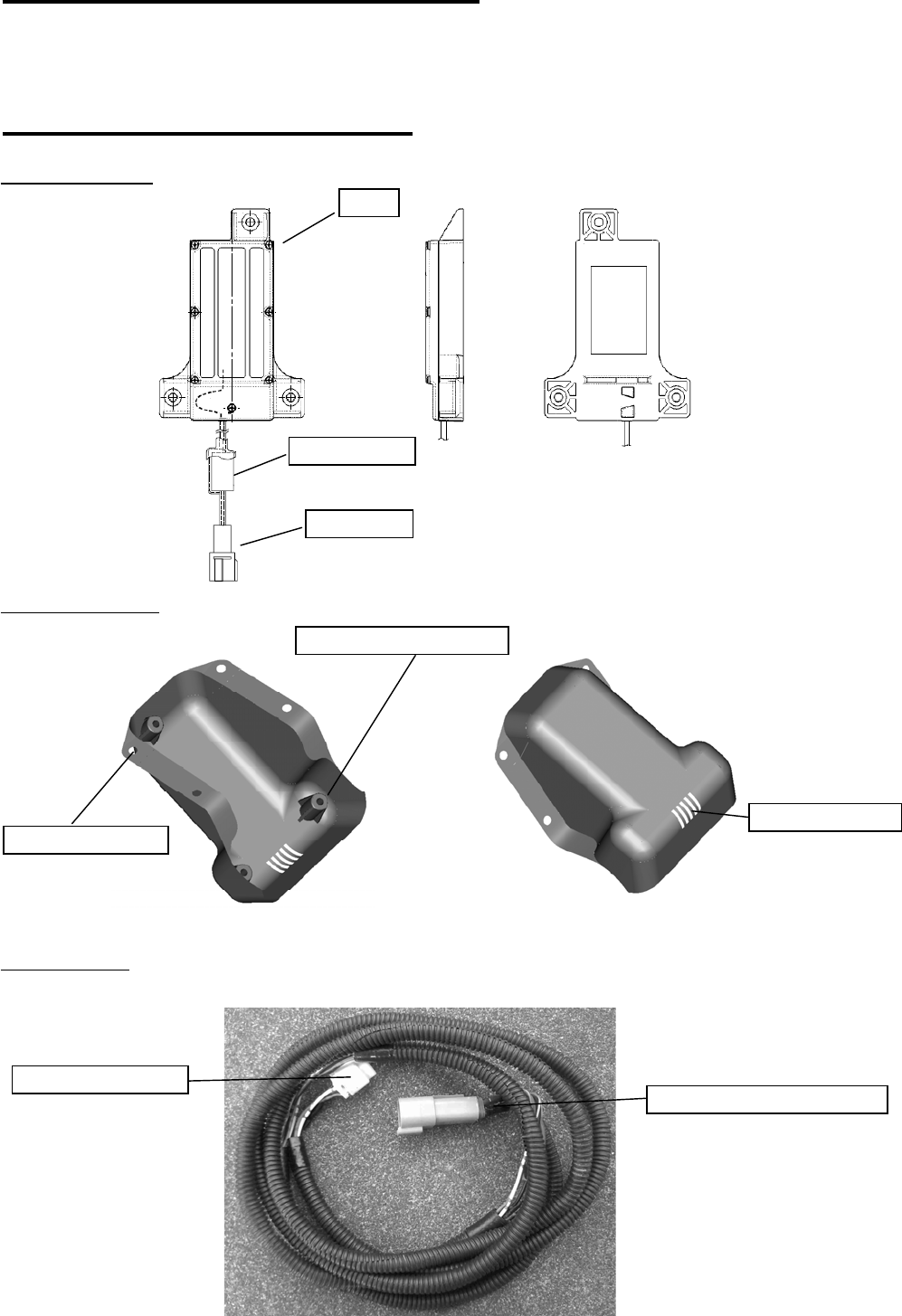
2. Parts and descriptions
䇭(1) Child device
䇭(2) Device cover
䇭(3) Wire lead
㪝㪼㫉㫉㫀㫋㪼㩷㪺㫆㫉㪼
㪩㫆㫆㪽㩷㫄㫆㫌㫅㫋㩷㪿㫆㫃㪼
㪙㫆㪻㫐
㪚㫆㫅㫅㪼㪺㫋㫆㫉
㪛㪼㫍㫀㪺㪼㩷㫄㫆㫌㫅㫋㫀㫅㪾㩷㪹㫆㫊㫊
㪮㫀㫉㪼㩷㪿㪸㫉㫅㪼㫊㫊㩷㪺㫆㫅㫅㪼㪺㫋㫆㫉
㪛㪼㫍㫀㪺㪼㩷㪺㫆㫅㫅㪼㪺㫋㫆㫉
㪮㪸㫋㪼㫉㩷㪻㫉㪸㫀㫅㩷㫊㫃㫀㫋㫊
(
The
g
eneral term Child device in the text means a TERMINAL UNIT.
)
䇭
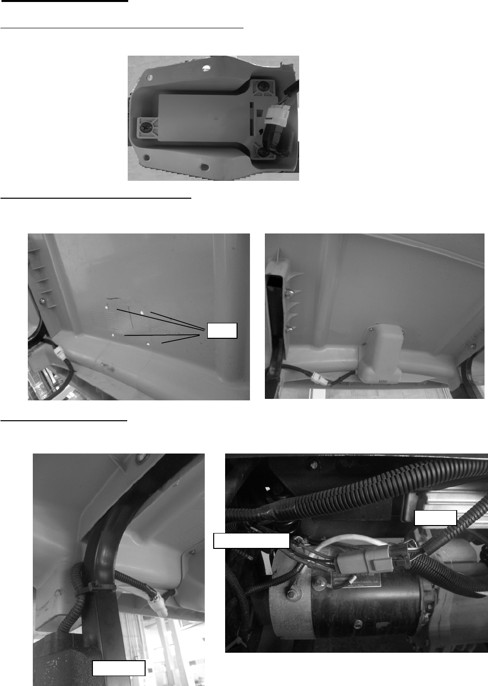
3. Installation
䇭(1) Install the child device onto the device cover.
Use three tapping screws to mount the child device on the device cover.
Connect the wire lead to the child device.
䇭(2) Install the child device on the roof.
Drill four holes on the roof, and then secure the device cover on the roof via
the bolts and nuts.
䇭(3) Install the wire leads.
Route the wire lead through the gutter into the rear cowl.
Connect the wire lead to the wire harness inside the rear cowl.
㪟㫆㫃㪼
㪞㫌㫋㫋㪼㫉
㪮㫀㫉㪼
㪮㫀㫉㪼㩷㫃㪼㪸㪻

!
䇭
Caution
䋺
Do not disassemble the transmitter. Contact Yamaha Service if the device
requires service or repair.
!
䇭
Caution
䋺
Secure the wire lead on the frame. Don't allow it to contact the motor or
other rotating objects or the hot portions.
Secure the wire lead on the vehicle frame so that it won't reach below
the vehicle frame.
䇭
4. Operation
䇭䇭(1) Setting up the Vehicle Management PC
䇭䇭䇭䇭Refer to the separate "Vehicle Management Software Installation Manual".
䇭䇭(2) Registering the vehicles and the relay devices
䇭䇭(3) How to use the Vehicle Management software
䇭䇭䇭䇭Please refer to the separate document, "Vehicle Management System:
JW9-85560-00 Parent device, JW9-8A2F0-00 Relay device".
FCC WARNING
Changes or modifications not expressly approved by the party responsible for compliance could
void the user's authority to operate the equipment.
Note. This equipment has been tested and found to comply with the limits for a Class A digital
device , pursuant to part 15 of the FCC Rules. These limits are designed to provide reasonable
protection against harmful interference when the equipment Is oparated in a commercial
environment. This equipment generates, uses, and can radiate radio frequency energy and, if
not installed and used in accordance with the instruction manual, may cause harmful
interference to radio communications, Operation of this equipment in a residential area is likely
to cause harmful interference in which case the user will be required to correct the interference
at his own expence.
䋭The cable of child unit with ferrite core must be used for RF Interference suppression.

䇭
5. Equipment specifications
In service䋺CH1 (default)
Item Specifications Remarks
Product model type JW9-85579-00
External dimensions 106 X 153 X 27.5mm
Product weight About 170g
Region USA
Operating -10䌾60㷄
Operating humidity 85%Rh or lower No formation of dew
Rated Voltage DC 5V ± 0.5V
Max. power
consumption 35mA or less
Interface standard RS-232C serial communication
Interface data
transmission 9600bps
Connector
specifications
䊶Housing䋺6188-0004
䊶Terminal䋺1500-0105
䊶Pin layout
䇭1pin DC5V䋨red䋩
䇭2pin GND䋨black䋩
䇭3pin data receive (blue)
䇭4pin data send (yellow)
Communication Simplex communication system
Operating
frequencies
CH0䋺916.2204MHz On registration䋺CH0
CH1䋺918.0636MHz
CH2䋺919.9068MHz
CH3䋺921.7500MHz
Type of oscillation PLL synthesizer type
Type of modulation 2-value FSK
Coding NRZ
Aerial type Dielectric chip antenna
Electric field
stren
g
th, send Less than 93.9dBuV/m By 3m method
Spurious radiation
stren
g
th 0.1uW (-40dBm) or lower Maximum electric power up
to tertiar
y
harmonics at end
Frequency deviation Within 32±15kHz By 511bit STD encoded
si
g
nal at 19200b
p
s
Signal reception
level settin
g
Level 4-5 threshold䋺33dBuVemf
Level 3-4 threshold䋺23dBuVemf
Collateral radiation
stren
g
th 0.1uW (-40dBm) or lower Maximum electric power
between 0䌾3GHz at end of
Sensitivity to
rece
p
tion 15dBuVemf or lower Per standard data at
19200b
p
s, DEV32kHz, and