Yaesu Musen 20605X20 Analog Scanning Receiver User Manual part 2
Yaesu Musen Co., Ltd. Analog Scanning Receiver part 2
Contents
- 1. User Manual - part 1
- 2. User Manual - part 2
- 3. User Manual - part 3
- 4. User Manual - part 4
User Manual - part 2
11
Before Using the Transceiver
Names and Functions of Controls
Touch Screen Display
メモリー書き込み中!A1
①
②
③
④
⑦ ⑪ ⑫
⑬
⑤
⑥
④
⑤
⑥
⑧
⑭
⑬
⑭
⑨ ⑩
⑮
⑩
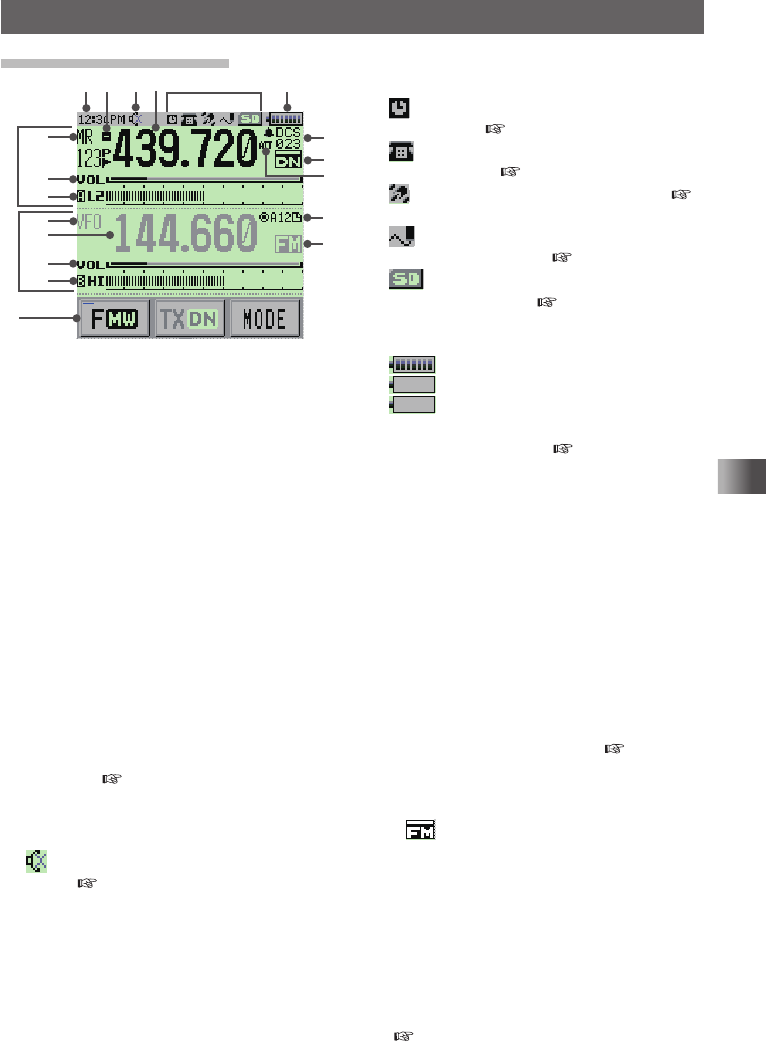
①This is the A-band display area�
②This is the B-band display area�
③Displays touch keys�
④Displays mode�
In VFO mode, “VFO” is displayed�
In Memory mode, “MR” and the channel
number are displayed�
⑤Gauge displays the sound volume level�
⑥Displays the icon of the transmission
output, the S meter and the PO meter�
S meter: Displays the radio wave strength
in 9 steps�
PO meter: Displays the transmission power
level in 4 steps�
H I: High power (5W)
L 3: LOW 3 power (2�5W)
L 2: LOW 2 power (1W)
L 1: LOW 1 power (0�1W)
⑦Displays the time�
⑧Displays a shift direction during repeater
operation ( see page xx)�
-: Minus shift
+: Plus shift
@: Split operation
⑨ lights up when the Mute function is
active ( see page xx)�
⑩Displays the frequency�
⑪Displays icon types�
: Lights up when the APO function is
active ( see page xx)�
: Lights up when the DTMF function is
enabled ( see page xx)�
: Lights up when GPS is acquired (
see page xx)�
: Lights up when a microSD memory
card is inserted ( see page xx)�
: Lights up when using a microSD
memory card ( see page xx)�
⑫The battery condition is displayed in 8
steps�
: Full battery power
: Battery is depleted� Charge battery�
: (When blinking) Charge battery
immediately�
⑬Displays squelch type ( see page xx)
TN: Lights up when the tone encoder
function is enabled�
TSQ: Lights up when the tone squelch
function is enabled�
DCS: Lights up when the DCS function is
enabled�
RTN: Lights up when the reverse tone
function is enabled�
JR:
Lights up when the JR idle signal
squelch function is enabled�
PR: Lights up when the idle signal
squelch function is enabled�
PAG: Lights up when the pager is
enabled�
Displays the APRS baud rate ( APRS
function Instruction manual)�
⑭Displays operation mode�
FM: FM (Analog) mode
: Auto mode (automatic switching
among Analog AM, Analog FM,
and Digital) *The display of the
“FM” portion differs according to
the selected mode�
DN: Wide digital mode (digital mode
using C4FM modulation)
VW: Wide digital mode (high-quality
digital communication)
⑮b appears when the bell function is active
( see page xx)�
Application for FCC / IC
FCC ID: K6620605X20
IC: 511B-20605X20
12
Before Using the Transceiver
Names and Functions of Controls
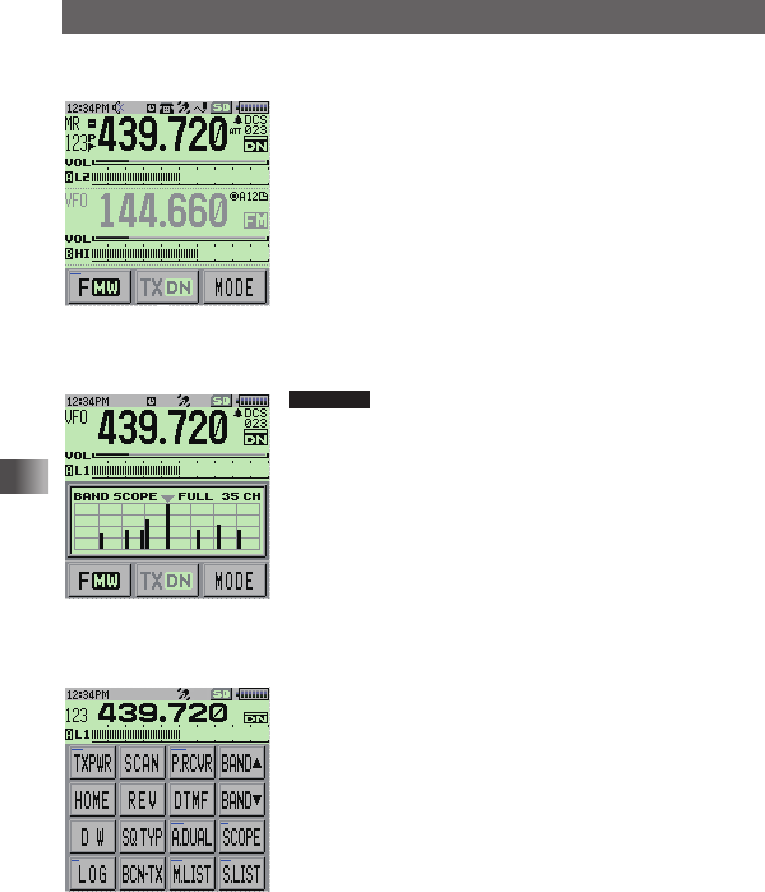
yDual Band Screen
A-band and B-band are displayed in a top-down fashion�
メモリー書き込み中!A1
• Touching [F MW] displays the function menu screen�
• Touching [TX DN] enables for the communication mode
to be fixed on the transmission side�
• Touching [MODE] switches between Analog and Digital�
yBand Scope Screen
When the band scope operation is enabled, the display is as follows�
Reference You can change the number of band scope channels by
selecting [DISPLAY] → [4 BAND SCOPE] in Set mode�
You can select 17 channels, 35 channels or 71 channels�
yFunction Menu Screen
Touching [F MW] displays the function menu screen�
MENU DISPLAY 2'!A7723 TOP画面プリセットレシーバー!A1
TOP画面AF-DUAL表示'!A1 Band Scope'!A1
FUNCTION!A389 APRS Message list1'!A1
APRS Station list1'!A1
Application for FCC / IC
FCC ID: K6620605X20
IC: 511B-20605X20

13
Before Using the Transceiver
Names and Functions of Controls
yBACKTRACK Screen
Pressing the key displays the BACKTRACK screen�
• The compass setting is displayed to the upper left of the
compass icon� “H-UP” is displayed when the direction
in which you are heading is set to always facing up,
whereas “N-UP” is displayed when North is set to always
facing up� In the Set mode option [DISPLAY] → [3
COMPASS], you can change the compass setting�
• Upon retrieval of the registered position information, the
distance from the current position displays to the upper
right of the compass icon�
• Touching [YR] displays the position of the received friend
station displays on the compass icon (only when the
signal carries the position information)�
• Touching [MY] displays your heading direction on the
compass icon�
• Touching [MEMORY] switches to the mode for registering
the current position information�
• Touching [★] displays the position information registered
with the “★” tag� When touching while flashing, the
position information displayed on the compass icon is
stored in the memory with a “★” tag�
• Touching [L1] displays the position information registered
with the “L1” tag� When touching while flashing, the
position information displayed on the compass icon is
stored in the memory with an “L1” tag�
• Touching [L2] displays the position information registered
with the “L2” tag� When touching while flashing, the
position information displayed on the compass icon is
stored in the memory with an “L2” tag�
Application for FCC / IC
FCC ID: K6620605X20
IC: 511B-20605X20
14
Before Using the Transceiver
Names and Functions of Controls
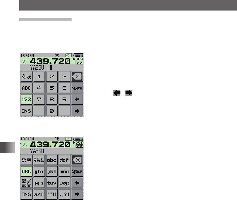
Entering Letters
The keyboard screen appears for inputting letters such as your call sign or a memory
channel tag�
yNumber & Symbol Input Screen
• Touch [ABC] to display the alphabet input screen�
• Touching [123] switches the key to [#&%] and displays
the symbol input screen� Touching each time switches
between the number input screen and the symbol input
screen�
• Touch [] [ ] to move the cursor to left/right in the text
input area�
yAlphabet Input Screen
• Touching [ABC] each time switches between upper case
letters and lower case letters�
Application for FCC / IC
FCC ID: K6620605X20
IC: 511B-20605X20
15
Preparation
Preparation
Attaching the Supplied Accessories
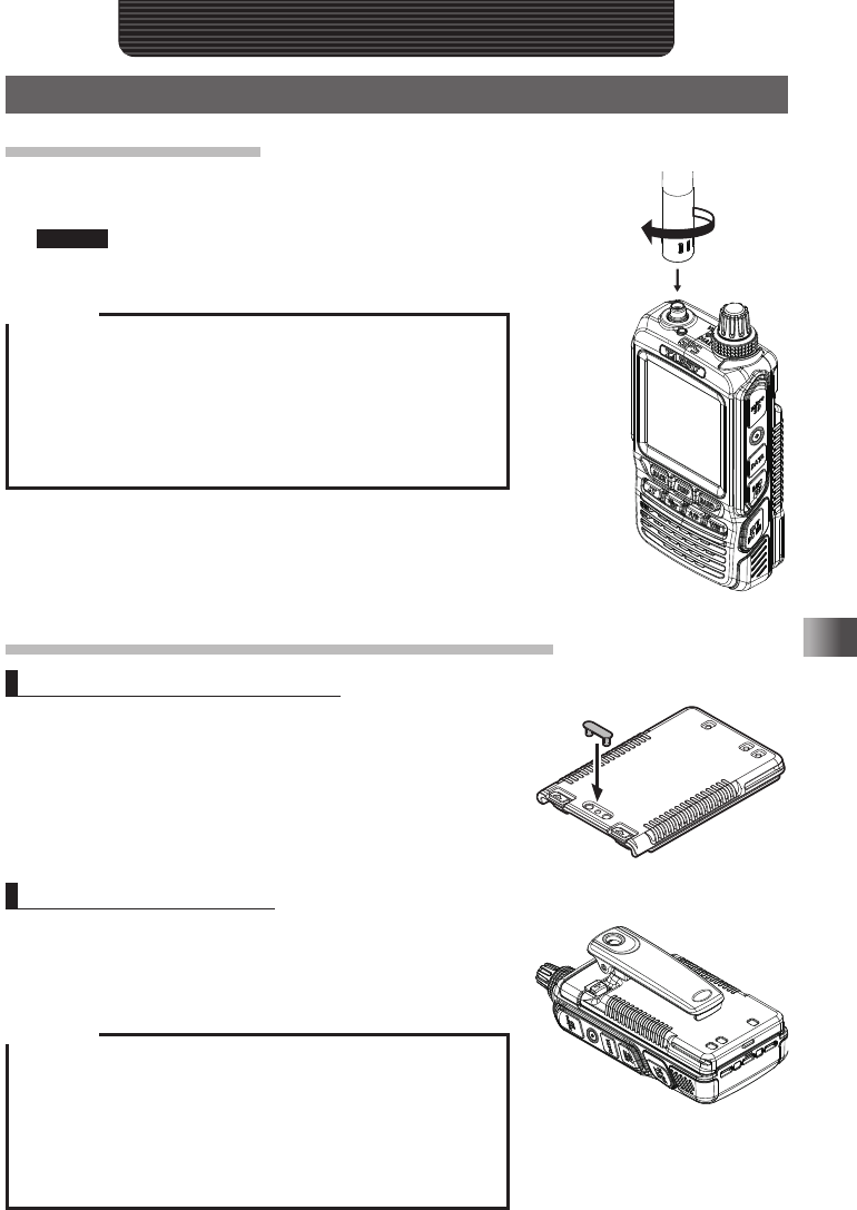
Installing the Antenna
1 Align the bottom side of the antenna with the antenna terminal on
the transceiver�
Caution Be sure to hold the thick base of the antenna when installing it
2 Turn the antenna clockwise until it is secured�
Cautions
yDo not hold the upper part of the antenna when installing or
removing it� To do so, the wire inside the antenna may break�
yDo not transmit without installing the antenna� The transmitter
circuit can be damaged�
yWhen using an antenna other than the supplied one or any
other external antenna, ensure that its SWR is adjusted to 1�5
or lower�
Attaching the Accessory Belt Clip/Protective Cap
Attaching the Protective Cap
If you do not use the belt clip, attach the protective cap to
the belt clip attaching screw holes on the battery pack�
Attaching the Belt Clip
1 Turn over the battery pack�
2 Attach the belt clip to the battery pack using the
supplied screws (two)�
Cautions
yBe sure to use the supplied screws when attaching the
belt clip� If any other screws are used, the belt clip cannot
be secured firmly to the battery pack and the transceiver
may drop off together with the battery pack, causing injury,
breakage and other troubles�
yBe sure to attach the protective cap when the belt clip is not
used�
Application for FCC / IC
FCC ID: K6620605X20
IC: 511B-20605X20

16
Preparation
Attaching the Supplied Accessories
Attaching a Hand Strap
If you attach a hand strap to the transceiver, use its 1 mm diameter string which is
inserted in and secured to the strap hole of the transceiver�
* The hand strap is not supplied�
1 Remove the battery pack�
2 Attach the hand strap�
Caution
Use a hand strap which can withstand the weight of the
transceiver� If you use a hand strap which is not strong enough,
the hand strap can break and the transceiver may fall down,
causing injury, breakage and other troubles�
T�B�D�
Application for FCC / IC
FCC ID: K6620605X20
IC: 511B-20605X20
17
Preparation
Preparing the Battery Pack/External Power Supply
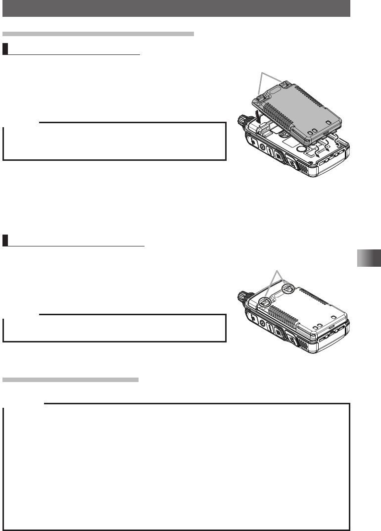
Installing/Removing the Battery Pack
Installing the Battery Pack
1 Insert the bottom tabs of the battery pack in the slots
on the back side lower part of the transceiver�
2 Push the battery in until the battery latches click
securely�
Caution
When you use the transceiver for the first time after purchase or
you have not used it for a long period, charge the battery pack
before use�
Removing the Battery Pack
1 While pressing down the latches, remove the battery
pack�
Press down the latches to the direction of arrows as
shown in the illustration�
Caution
When releasing the battery latches, be careful not to hurt your
fingers and nails�
Charging the Battery Pack
Cautions
yThe battery pack is rechargeable about 300 times� However, improper use such as overcharge or
over-discharge can shorten its service life�
yThe battery pack is a consumable item� Recharging the battery pack repeatedly will gradually
shorten the duration of its usage�
yIf the transceiver is not used for a long period with the battery pack installed, deterioration of the
battery pack can accelerate�
yIf you do not use the transceiver for a long period, be sure to store it with the battery pack removed�
Even if you do not use the transceiver for a long period, install the battery pack biannually and
recharge the battery pack about 50% to prevent it from over-discharging�
yStoring the battery pack in a high-temperature place can deteriorate it faster than usual� Store the
battery pack in a place where the ambient temperature is −20 °C to +50 °C (−4 °F to +122 °F).
yBe careful not to drop or give a strong shock to the battery pack� It can break�
Battery latches
Press down on the latches
in the direction of the arrow.
Application for FCC / IC
FCC ID: K6620605X20
IC: 511B-20605X20

18
Preparation
Preparing the Battery Pack/External Power Supply
Tips
• The battery pack contains lithium-ion batteries that can be recharged for repetitive use�
• The transceiver can be used with either of the following battery packs:
(1) Supplied battery pack: SBR-14LI (7�2 V, 2,200 mAh)
(2) Optional battery pack: FNB-102LI (7�4 V, 1,800 mAh)
• When the battery pack is recharged, its output voltage becomes higher (about 8 V) than the
specified value (7�4 V)� This is not a malfunction�
AC100V
Battery charger
PA-48A (supplied)
Grooves in
battery pack
Rails
Rapid Charger Cradle CD-41
(optional)
1 Install the battery pack�
2 Turn off the transceiver�
3 Insert the plug of the battery charger (PA-48) in the
EXT DC IN jack of the transceiver�
Charging starts�
While the battery is being charged, lights red and the
display indicates “NOW CHARGING”�
The charge level is indicated by a bar graph�
It takes about 8 hours to charge the battery pack fully�
When charging is completed, the display will change
to indicate “COMPLETE” and the lamp will light green�
充電中
FT1D
充電完了
T�B�D�
T�B�D�
Application for FCC / IC
FCC ID: K6620605X20
IC: 511B-20605X20
19
Preparation
Preparing the Battery Pack/External Power Supply
Supplements • It takes about 8 hours to charge the FNB-102LI (optional)�
• The optional Rapid Charger Cradle (CD-41) requires about 4 hours to charge the
supplied battery pack (about 2�5 hours to charge the optional battery pack FNB-
102LI)�
Place the battery pack on the CD-41 so that the rails of the CD-41 fit into the
grooves on the battery pack�
When charging the battery pack using the CD-41, the LED on the CD-41 indicates
the state of charging�
During charging: Lights red → Fast blinks → Slowly blinks
Completion of charging: Lights green
4 Remove the plug of the battery charger from the jack of the transceiver�
Cautions
yNeither transmission nor reception can be performed while charging the battery pack using the
supplied battery charger�
yCharging may cause noise in the nearby TV or radio�
Charge the battery pack with the battery charger as far away as possible from a TV or radio�
yIf “BATTERY NOT INSTALLED” appears on the LCD and the battery pack cannot be charged after
lapse of 11 or more hours, stop charging the battery pack immediately�
If the same message appears again, the battery pack is presumably at the end of its service life or
defective� In such a case, replace the battery pack with a new one�
yWhile charging the battery pack, protect the transceiver from water�
yCharge the battery pack in a place where the ambient temperature is +5 °C to +35 °C (+41 °F to
+95 °F).
yIf the terminal or electrode of the battery case is dirty, this transceiver can malfunction due to poor
contact, resulting in overheating or rupture� If the terminal or electrode gets dirty, clean it using a dry
cloth or cotton swab�
Tips
• The battery charger may become hot during charging� This is not a malfunction�
• If starts blinking, the battery pack charge is depleted� Charge it immediately�
Approximate Operating Time and Remaining Charge Level Indication
Approximate time to operate the transceiver with the fully charged battery pack or new
AA alkaline batteries is as follows:
Band in Use
Digital: OFF Battery pack
FNB-102LI Battery pack
SBR-14LI Battery
FBA-39
Amateur Band
144 MHz band Approx� 8�0 hours Approx� 8�0 hours Approx� 15�5 hours
430 MHz band Approx� 7�5 hours Approx� 7�5 hours Approx� 15�0 hours
AM Broadcast Band Approx� 16�0 hours Approx� 16�0 hours Approx� 18�0 hours
FM Broadcast Band Approx� 13�0 hours Approx� 13�0 hours Approx� 14�5 hours
Band in Use
Digital: ON Battery pack
FNB-102LI Battery pack
SBR-14LI Battery
FBA-39
Amateur Band
144 MHz band Approx� 6�5 hours Approx� 6�5 hours Approx� 11�0 hours
430 MHz band Approx� 6�0 hours Approx� 6�0 hours Approx� 10�5 hours
Transmission 6 seconds: Reception 6 seconds (VOL Level 16): Stand By 48 seconds (SAVE1:5)
Application for FCC / IC
FCC ID: K6620605X20
IC: 511B-20605X20
20
Preparation
Preparing the Battery Pack/External Power Supply
Remark Approximate hours are estimated assuming that the transceiver is operated under the
following conditions� The operation time that this transceiver can be actually used varies
depending on use conditions, ambient temperature, etc�
• When the GPS function is deactivated�
• When the transceiver is repeatedly operated by high-power transmission for 6 seconds
and reception for 6 seconds, and standby for 48 seconds with an amateur ham radio
band selected�
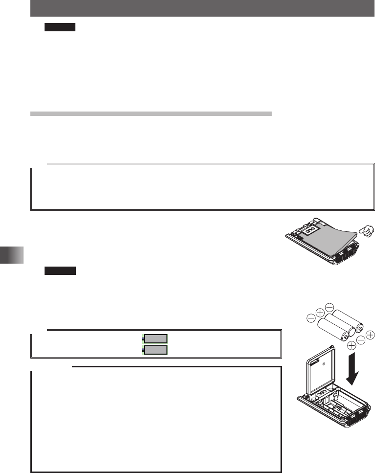
How to Use the Battery Case (FBA-39) Optional
The optional battery case (FBA-39) allows 3 AA Alkaline batteries to be used for the
power supply�
Tip
When the battery case (FBA-39) is used, you can select a power output level from:
Low Power (L1): 0�1 W
Low Power (L2): Approximately 0�8 W
Note that Low Power (L3) and High Power are not available�
1 Open the cover�
Lift up the lower right corner of the cover as indicated by the
hand pointer in the illustration�
2 Put alkaline batteries in the battery case�
Caution Use 3 alkaline batteries. Pay attention to polarities (+ and −)
of the alkaline batteries�
3 Close the cover�
Push the four corners of the cover firmly to close it tightly�
Tip
When the battery charge is low, lights on the LCD� When the
batteries are almost exhausted, blinks on the LCD�
Cautions
yManganese batteries cannot be used� Rechargeable AA batteries
cannot be used, either�
yDo not mix new and old batteries� The service life of new batteries may
decrease�
yIf you do not use the transceiver for a long period, remove the batteries
from the battery case�
yIf the terminal or electrode of the battery case is dirty, the transceiver
can malfunction due to poor contact, resulting in overheating or
explosion� If the terminal or electrode gets dirty, clean it using a dry
cloth or cotton swab�
Application for FCC / IC
FCC ID: K6620605X20
IC: 511B-20605X20