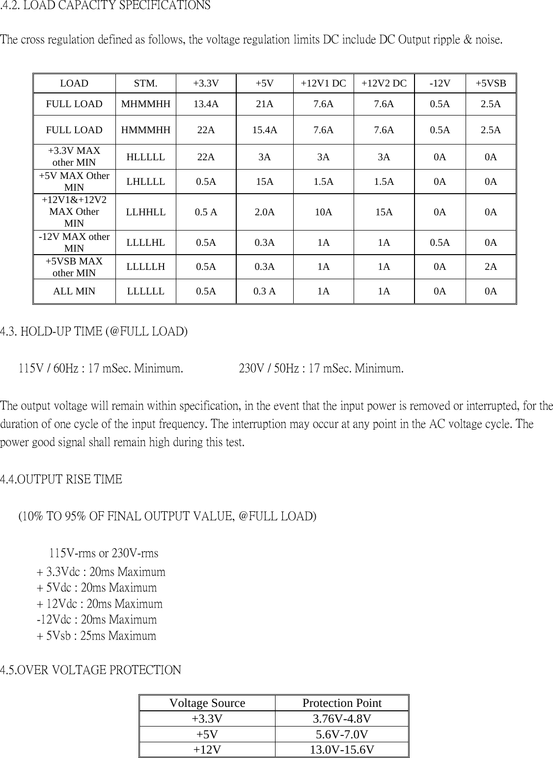
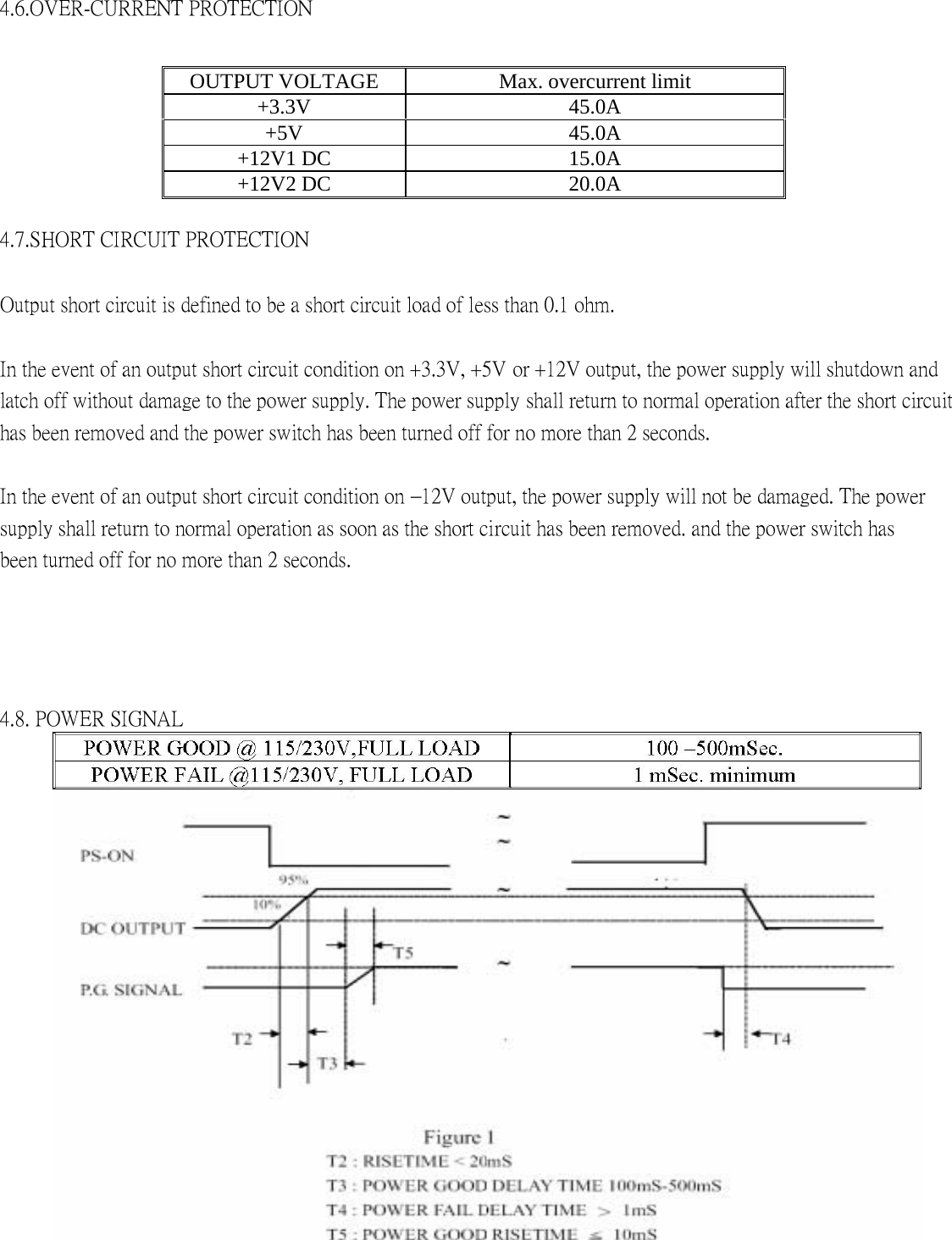
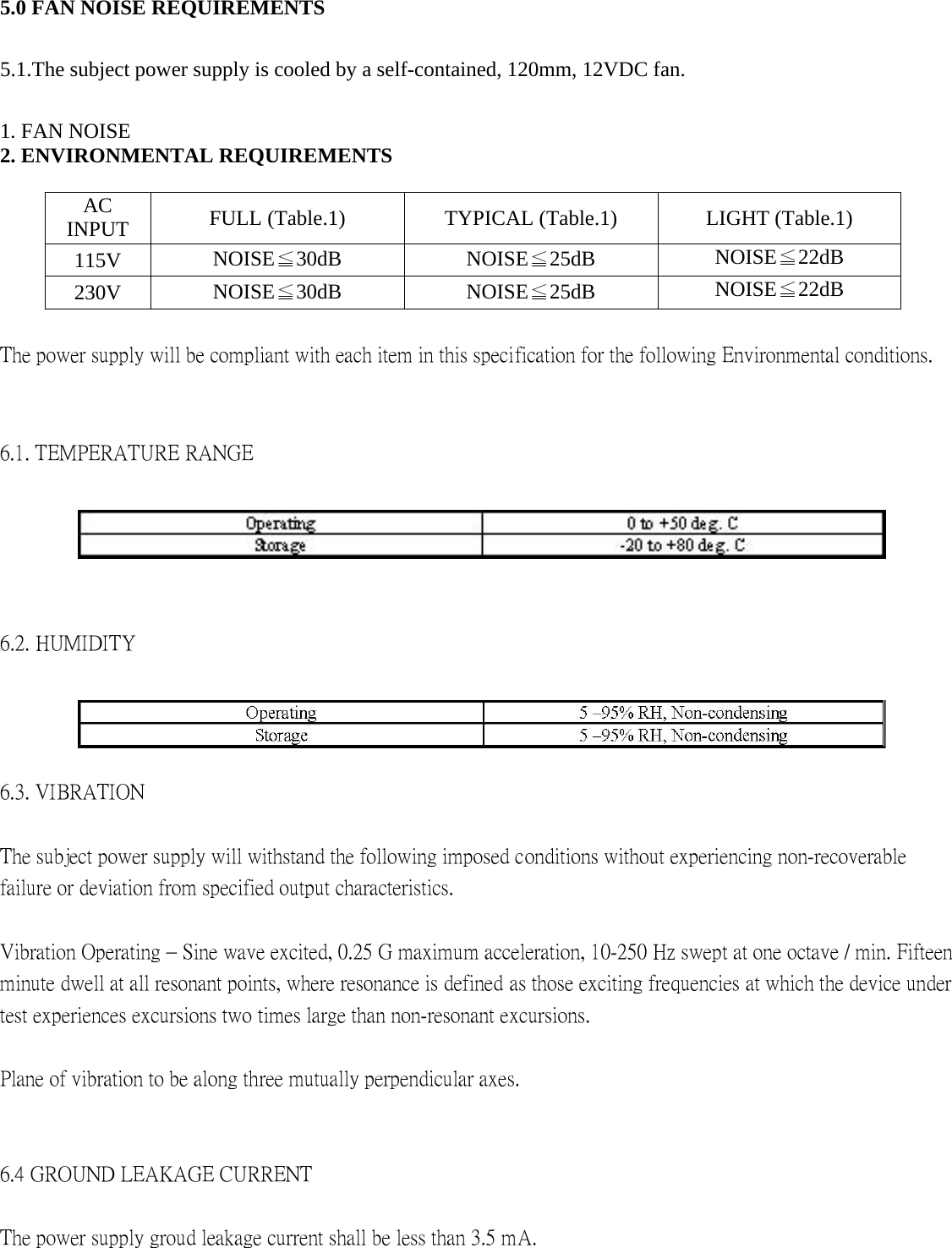
Zalman Tech ZM360B-APS Internal power supplies used with Class B PC User Manual SPECIFICATION

Zalman Tech Co., Ltd. Internal power supplies used with Class B PC SPECIFICATION

Users Manual

  SPECIFICATION  ZM360B-APS   9PA4601100   Main Feature: Low Noise High Efficiency Active PFC Circuit   Full Range Input   DEC 21, 2005   REV:01
MODEL: ZM360B-APS Revision History   Rev   Description   Date  Author 1.0   Released  2005/12/21                    1. GENERAL DESCRIPTION AND SCOPE    This is the specification of Model ZM360B-APS; AC-line powered switching power supply with active PFC (Power Factor Correction) circuit, meet EN61000-3-2 and with Full Range Input features.   The specification below is intended to describe as detailedly as possible the functions and performance of the subject power supply. Any comment or additional requirements to this specification from our customers will be highly appreciated and treated as a new target for us to approach.   2. REFERENCE DOCUMENTS   The subject power supply will meet the EMI requirements and obtain main safety approvals as following:   2.1 EMI REGULATORY    - FCC Part 15 Subpart J, Class ‘B’ 115 Vac operation.    - CISPR 22 Class ‘B’ 230 Vac operation.    2.2 SAFETY   - NEMKO EN 60950   - TUV EN60950 OR VDE EN60950 -CSA-C22.2 NO. 60950 -IEC 60950   - UL 60950   - CE : EN 55022:1998+A1: 2000, Class B EN 61000-3-2: 2000 EN 61000-3-3: 1995+A1: 2001     CISPR22: 1997+A1: 2000, Class B          AS/NZS CISPR 22: 2002, Class B
  Table. 1 Loading Table for Efficiency Measurements    360W(loading shown in Amps)   Loading +12V1 +12V2  +5V  +3.3V  -12V   +5Vsb Full   11.0   13.0  9.0  10.0  0.3   2.0   Typical   5.0   9.0  3.0  5.0   0.1   1.0   Light   3.0   3.5  1.0  2.0   0.0   1.0    Table 2. Minimum Efficiency Vs Load  Loading   Voltage   Full load  Typical load   Light load Required Minimum Efficiency   115V   75%   75%   70%   Required Minimum Efficiency   230V   80%   80%   75%    3.5 MECHANICAL SPECIFICATIONS   The mechanical drawing of the subject power supply, which indicate the form factor, location of the mounting holes, location, the length of the connectors, and other physical specifications of the subject power supply. Please refer to the attachment drawing.   4.0. OUTPUT ELECTRICAL REQUIREMENTS   4.1 OUTPUT VOLTAGE AND CURRENT RATING   Output   MINIMUM LOAD   NORMAL LOAD   MAXIMUM LOAD   LOAD REG  LINE REG.   RIPPLE&NOISE   RIPPLE +3.3V   0.5A   11A    22A   ±5%   ±1%   100mV P-P    50mV P-P +5V   0.3A   10.5A    21A   ±5%   ±1%   100mV P-P    50mV P-P +12V1   1A   5A    11 A    ±5%   ±1%   200mV P-P    120mV P-P +12V2   1A   7.5A    15A   ±5%   ±1%   200mV P-P    120mV P-P -12V   0A   0.15A    0.5A   ±10%  ±1%   200mV P-P    120mV P-P +5VSB   0A   1.25A    2.5A   ±5%   ±1%   100mV P-P    50mV P-P   ( 1 ) +3.3V & +5V total output not exceed 150W.    ( 2 ) +3.3V & +5V & +12V1 & +12V2 total output not exceed 347W    ( 3 ) total output for this subject power supply is 360 watts    ( 4 ) +5VSB Peak current loading is 3A , shall be supported for a minimum of 500m second.
.4.2. LOAD CAPACITY SPECIFICATIONS    The cross regulation defined as follows, the voltage regulation limits DC include DC Output ripple & noise.   LOAD   STM.   +3.3V   +5V   +12V1 DC  +12V2 DC    -12V    +5VSB FULL LOAD   MHMMHH  13.4A   21A   7.6A  7.6A  0.5A   2.5A  FULL LOAD   HMMMHH  22A   15.4A   7.6A  7.6A  0.5A   2.5A  +3.3V MAX other MIN    HLLLLL   22A   3A   3A   3A   0A   0A  +5V MAX Other MIN   LHLLLL   0.5A   15A   1.5A   1.5A   0A   0A  +12V1&+12V2 MAX Other MIN   LLHHLL   0.5 A   2.0A   10A   15A   0A   0A  -12V MAX other MIN   LLLLHL   0.5A   0.3A   1A   1A   0.5A   0A  +5VSB MAX other MIN    LLLLLH   0.5A   0.3A   1A   1A   0A   2A  ALL MIN   LLLLLL   0.5A   0.3 A   1A   1A   0A   0A   4.3. HOLD-UP TIME (@FULL LOAD)   115V / 60Hz : 17 mSec. Minimum.           230V / 50Hz : 17 mSec. Minimum.   The output voltage will remain within specification, in the event that the input power is removed or interrupted, for the duration of one cycle of the input frequency. The interruption may occur at any point in the AC voltage cycle. The power good signal shall remain high during this test.   4.4.OUTPUT RISE TIME   (10% TO 95% OF FINAL OUTPUT VALUE, @FULL LOAD)       115V-rms or 230V-rms        + 3.3Vdc : 20ms Maximum    + 5Vdc : 20ms Maximum  + 12Vdc : 20ms Maximum  -12Vdc : 20ms Maximum  + 5Vsb : 25ms Maximum    4.5.OVER VOLTAGE PROTECTION    Voltage Source    Protection Point   +3.3V   3.76V-4.8V  +5V   5.6V-7.0V  +12V   13.0V-15.6V
4.6.OVER-CURRENT PROTECTION OUTPUT VOLTAGE    Max. overcurrent limit   +3.3V   45.0A  +5V   45.0A  +12V1 DC    15.0A   +12V2 DC    20.0A    4.7.SHORT CIRCUIT PROTECTION   Output short circuit is defined to be a short circuit load of less than 0.1 ohm.   In the event of an output short circuit condition on +3.3V, +5V or +12V output, the power supply will shutdown and latch off without damage to the power supply. The power supply shall return to normal operation after the short circuit has been removed and the power switch has been turned off for no more than 2 seconds.   In the event of an output short circuit condition on –12V output, the power supply will not be damaged. The power supply shall return to normal operation as soon as the short circuit has been removed. and the power switch has been turned off for no more than 2 seconds.   4.8. POWER SIGNAL
5.0 FAN NOISE REQUIREMENTS   5.1.The subject power supply is cooled by a self-contained, 120mm, 12VDC fan.   1. FAN NOISE   2. ENVIRONMENTAL REQUIREMENTS    AC INPUT   FULL (Table.1)    TYPICAL (Table.1)    LIGHT (Table.1)   115V   NOISE≦30dB   NOISE≦25dB   NOISE≦22dB  230V   NOISE≦30dB   NOISE≦25dB   NOISE≦22dB   The power supply will be compliant with each item in this specification for the following Environmental conditions.   6.1. TEMPERATURE RANGE     6.2. HUMIDITY  6.3. VIBRATION   The subject power supply will withstand the following imposed conditions without experiencing non-recoverable failure or deviation from specified output characteristics.   Vibration Operating – Sine wave excited, 0.25 G maximum acceleration, 10-250 Hz swept at one octave / min. Fifteen minute dwell at all resonant points, where resonance is defined as those exciting frequencies at which the device under test experiences excursions two times large than non-resonant excursions.   Plane of vibration to be along three mutually perpendicular axes.   6.4 GROUND LEAKAGE CURRENT   The power supply groud leakage current shall be less than 3.5 mA.
6.5 RELIABILITY   The power supply reliability,when calculated by MIL-HDBK-217;latest revision, are exceed 100,000 hours with all output at maximum load and an ambient temperature of 25℃.     6.6 DIELECTRIC STRENGTH   Primary to Frame Ground : 1800 Vac for 1 sec. Primary to Secondary : 1800Vac for 1 sec   6.7 INSULATION RESISTANCE   Primary to Frame Ground : 20 Meg.ohms Minimum Primary to Secondary : 20 Meg.ohms Minimum    7.0. LABELLING   Label marking will be permanent, legible and complied with all agency requirements.   7.1. MODEL NUMBER LABEL Labels will be affixed to the sides of the power supply showing the following:   - Manufacturer’s name and logo.   -Model no., serial no., revision level, location of manufacturer.   -The total power output and the maximum load for each output.   -AC input rating.
Note: This equipment has been tested and found to comply with the limits for a Class B digital device, pursuant to part 15 of the FCC Rules. These limits are designed to provide reasonable protection against harmful interference in a residential installation. This equipment generates, uses and can radiate radio frequency energy and, if not installed and used in accordance with the instructions, may cause harmful interference to radio communications. However, there is no guarantee that interference will not occur in a particular installation. If this equipment does cause harmful interference to radio or television reception, which can be determined by turning the equipment off and on, the user is encouraged to try to correct the interference by one or more of the following measures:    ◎  Reorient or relocate the receiving antenna.   ◎  Increase the separation between the equipment and receiver.   ◎  Connect the equipment into an outlet on a circuit different from that to which the receiver is connected.   ◎  Consult the dealer or an experienced radio/TV technician for help.    Modifications not expressly approved by the manufacturer could void the user's authority to operated the equipment under FCC rules.

Navigation menu