ZOWEE TECHNOLOGY USBWL170G WIRELESS USB ADAPTER User Manual WL 150G 1
Shenzhen Zowee Technology Co., Ltd. WIRELESS USB ADAPTER WL 150G 1
UserManual.wiki
>
ZOWEE TECHNOLOGY
>
USBWL170G User Manual
Users Manual
Navigation menu
Upload a User Manual
Namespaces
Wiki Guide
HTML
PDF
Info
Views
User Manual
Discussion / Help
Navigation
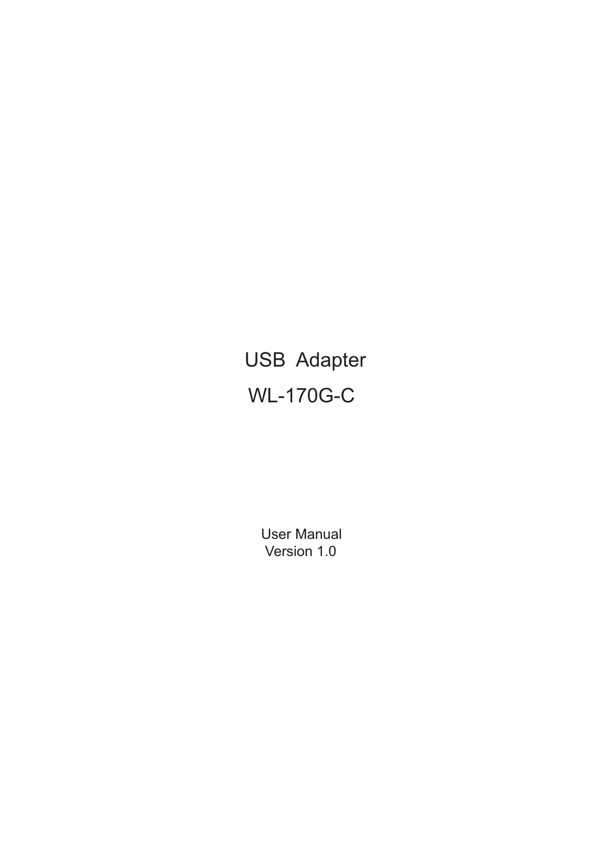
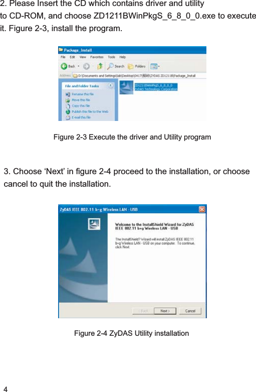
![65 Click ‘Finish” in Figure 2-7 to complete the installation.Figure 2-7 Installation Finish6. You can check if the Driver is well installed. Select [My Computer] icon on the desktop, right-click it and select [Attribute] icon, then select [Hardware] tab, click [Device Manager] icon. If your hardware driver has been installed ok, you can see the information as Figure 2-8.Figure 2-8 Device manage window](https://usermanual.wiki/ZOWEE-TECHNOLOGY/USBWL170G/User-Guide-861981-Page-7.png)
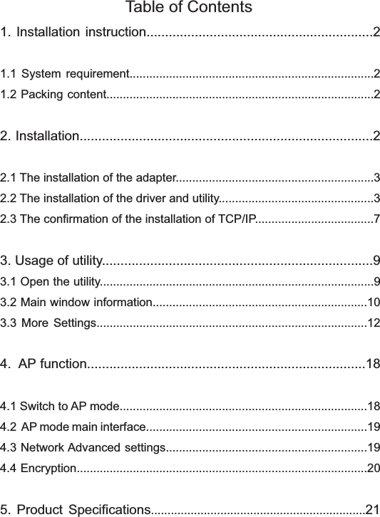
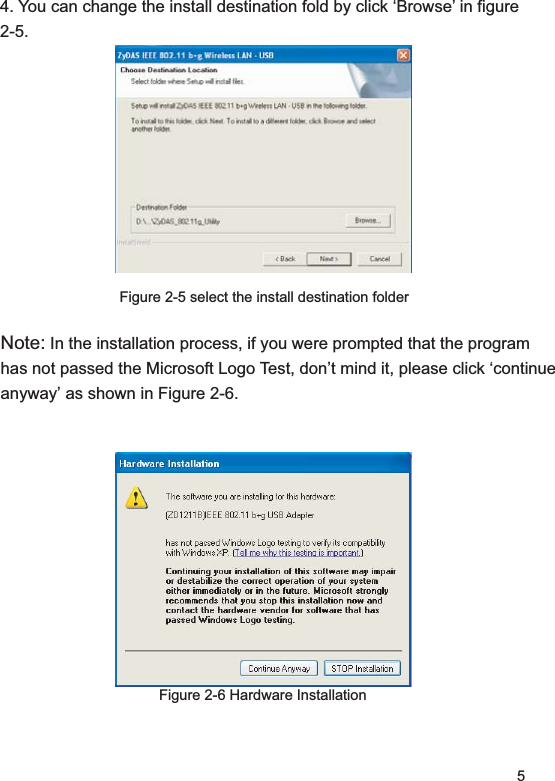
![72.3 Check if TCP/IP Protocol is installedTo ensure the adapter works well, your operation system should has been installed TCP /IP protocol. On Windows XP platform, TCP/IP Protocol is a default setting. (You can skip this section). If you are on other operation systems, please check first if this protocol is installed. On Windows XP platform, please check as the following steps: &OLFN>6WDUW@ĺ>&RQQHFWWR@ĺ>'LVSOD\DOOFRQQHFWLRQV@You will see the Network Connection as Figure 2-9.Figure 2-9 Network Connection Windows2. Right click and select [Attribute], the network connection properties will appear as figure 2-10, you can check if the TCP/IP Protocol has installed.](https://usermanual.wiki/ZOWEE-TECHNOLOGY/USBWL170G/User-Guide-861981-Page-8.png)
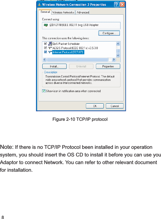
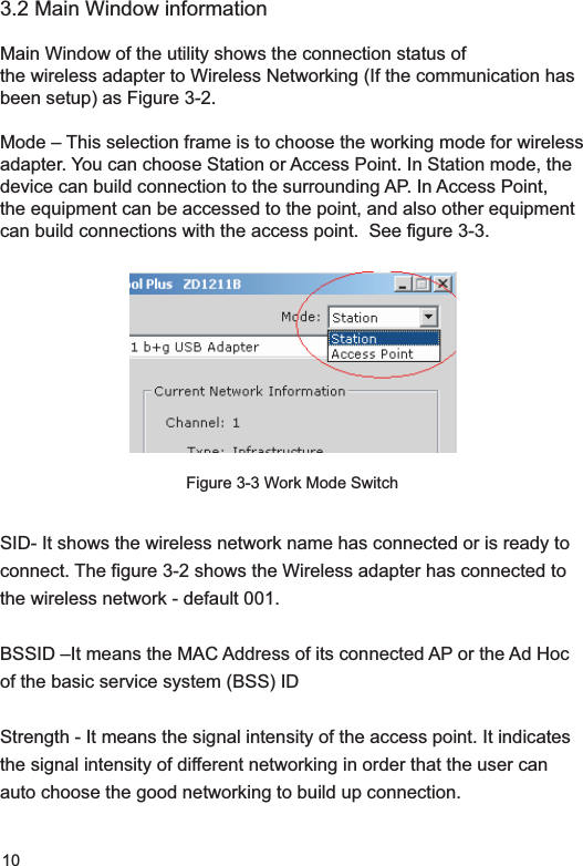
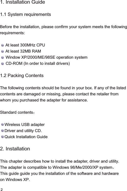
![123.4 More settingsMore settings — This website allows user to adjust the current working attribute , including transmission ratio, input networking SSID, networking topology structure, identity authentication and encryption mode , etc. User can also set up different working mode in one networking, and save them as different profile, avoid set up repeatedly when you re-using. [Normal connection setting]Tx Rate: Set-up the valid ratio, including: 54,48,36,24,18,12,9,6,11,5.5,2,1Mbps or automatically, normally use automatically. See Figure 3-4.Networking Type: change the network topology between Infrastructure and Ad Hoc Mode.Figure 3-4 More setting](https://usermanual.wiki/ZOWEE-TECHNOLOGY/USBWL170G/User-Guide-861981-Page-13.png)
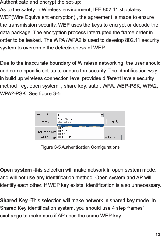
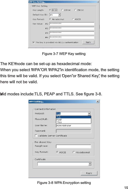
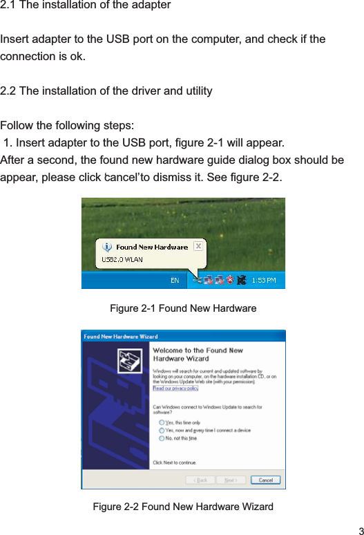
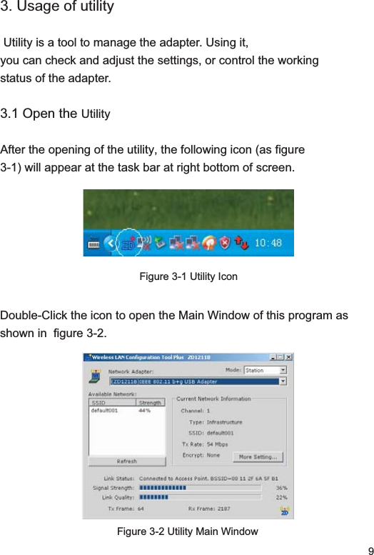
![14WPA-PSK This selection allows to use WPA Pre-Shared key. It allows user and AP to use WPA –PSK /WPA2-PSK encryption way. WPA/WPA2- The networking use IEEE 802.1x identification method. This method will use in RADIUS˄Remote Access Dial-in User Serviceˈlong-distance dial the user environment. RADIUS environment support EAP, including PEAP, TLS/Smart Card, TTLS and LEAP. Data EncryptionThe encryption method includes WEPˈ Temporal Key Integrity Protocol encryption and Advanced Encryption Standard (AES). See Figure 3-6.Figure 3-6 Encryption configurationsProhibit - Prohibit encryption function. WEP -- WEP is to encrypt before data wireless transmission, and use the same WEP wireless equipment to communicate. TKIP -- TKIP use the sticker encryption rule than WEP to encrypt. It also uses the WLAN arithmetic to encryption. TKIP will test the security setting once the encryption key is confirmed. AES – AES is a symmetrical 128 bit encryption technology. It can works in multi-layer in networking[WEP KEY Setting]This selection can set-up WEP KEY SETTING. WEP KEY is a cluster of 64 bytes(5 bites) , 128 bytes (13 bits) or 256 bytes (39 bits) , 16 hexadecimal figures to key or decode data package. See Figure 3-7.](https://usermanual.wiki/ZOWEE-TECHNOLOGY/USBWL170G/User-Guide-861981-Page-15.png)