ecobee orporated WEM01 AC/HP Wi-Fi Thermostat User Manual TP WEM 02SI
ecobee Incorporated AC/HP Wi-Fi Thermostat TP WEM 02SI
Contents
- 1. manual - ver 1
- 2. manual - ver 2
manual - ver 1
TP--WEM01
CarrierrCôr™ Thermostat
AC/HP Wi-FirThermostat
Performance™ Series
Installation Instructions
A14493
NOTE: Read the entire instruction manual before starting the installation.
TABLE OF CONTENTS
PAGE
SAFETY CONSIDERATIONS 1.................................
INTRODUCTION 2...........................................
INSTALLATION CONSIDERATIONS 2..........................
INSTALLATION 3............................................
Step 1. Power Off System 9.....................................
Step 2. Remove Existing Thermostat 10...........................
Step 3. Attach Backplate to Wall 11..............................
Step 4. Connect the Wiring 14...................................
Step 5. Power On System 16....................................
FEATURES 17...............................................
TROUBLESHOOTING 17......................................
WIRING DIAGRAMS 18.......................................

1
SAFETY CONSIDERATIONS
Read and follow manufacturer instructions carefully. Follow all local
electrical codes during installation. All wiring must conform to local
and national electrical codes. Improper wiring or installation may
damage thermostat. Recognize safety information. This is the
safety----alert symbol. When you see this symbol on the equipment and
in the instruction manual, be alert to the potential for personal injury.
Understand the signal words DANGER,WARNING,and
CAUTION. These words are used with the safety----alert symbol.
DANGER identifies the most serious hazards which will result in
severe personal injury or death. WARNING signifies a hazard which
could result in personal injury or death. CAUTION is used to identify
unsafe practices which may result in minor personal injury or product
and property damage. NOTE is used to highlight suggestions which
will result in enhanced installation, reliability, or operation.

2
INTRODUCTION
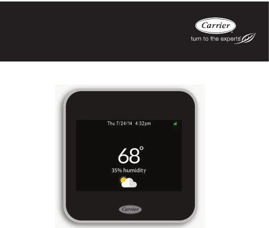
The CarrierrCôrtthermostat is a wall--mounted, low--voltage
thermostat which maintains room temperature by controlling the
operation of a heating and/or air conditioning system, both heat pump
and air conditioner models. Your Côr thermostat has a color touch
screen and interface similar to that used in smart phones. A variety of
features are provided including remote access through web and mobile
apps, separate heating and cooling setpoints, auto changeover, keypad
lockout, backlighting, and built--in installer test. Programing features
allow each day to be independently programmed in half an hour
increments with four preset periods (Home, Away, Sleep, Wake) and
up to six additional custom profile periods. For operational details,
consult the online Owner’s Manual for the specifics at
www.Carrier.com/homecomfort.
INSTALLATION CONSIDERATIONS
Power
This thermostat is powered by 24VAC through the C terminal and thus
most applications require a minimum of 5 thermostat wires. Provision
is made for separate heating and cooling transformers via separable Rc
and Rh terminals which are internally jumpered unless both Rc and Rh
are utilized. Internal jumper is controlled by a relay after the thermostat
senses whether Rc and/or Rh wires are connected to the terminal
block.

3
INSTALLATION
Installation Notes:
dThe maximum wire size to be used in the installation is
22AWG (0.50mm2) with 0.8mm insulation
dNo part of the control should be installed directly outdoors or
in a cabinet outdoors
dThe control assembly base should be mounted before wires are
attached
Thermostat location:
dApproximately 5 ft. (1.5m) from floor.
dClose to or in a frequently used room, preferably on an inside
partitioning wall.
dOn a section of wall without pipes or duct work.
Thermostat should NOT be mounted:
dClose to a window, on an outside wall, or next to a door lead-
ing to the outside.
dExposed to direct light or heat from the sun, a lamp, fireplace,
or near other temperature--radiating objects which could cause
a false reading.

4
dClose to or in direct airflow from supply registers and return--
air registers.
dIn areas with poor air circulation, such as behind a door or in
an alcove.
Compatible Systems
Your Carrier Côr thermostat works with most centralized residential
heating and cooling systems.
Heating: up to 2 stages
Cooling: up to 2 stages
Heat pumps: 1 or 2 stages + 1 or 2 stages auxiliary heat (Intelligent
heat staging capable)
Gas, oil, electric
Hybrid HeatrDual Fuel systems
Geothermal systems
Accessories: Humidifier, dehumidifier, or ventilator
5
Terminal Descriptions
GFan
Rc Cool transformer
Rh Heat transformer
O/B Heat pump reversing valve
Y/Y1 Used for first stage of conventional A/C or first
stage of heat pump compressor
Y2 Used for second stage of conventional A/C or
second stage of heat pump compressor
WW1, W2: Used for 1 -- 2 stages of conventional
heat or 1 -- 2 stages of electric auxiliary heat (3
stages -- Intelligent heat staging configuration)
C24VAC common
ACC Accessory (+/--): Used for dehumidifiers,
humidifiers, ventilators, HRVs or ERVs
This thermostat is designed for 24VAC with a 2A maximum current.
Do not connect it to line (high) voltage or millivolt systems.
6
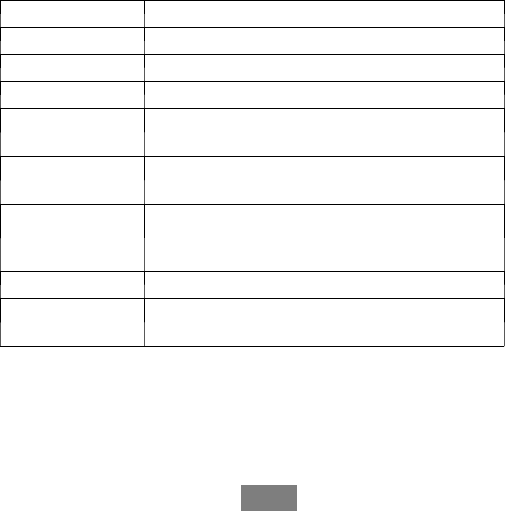
Items Included In Box
A14494
Fig. 1 -- Carrier CôrrThermostat
A14495
Fig. 2 -- Small Backplate
NOTE: The Mounting Plate (center) is removable for both backplates.
7
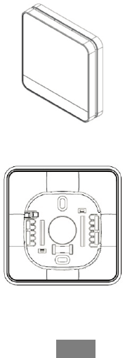
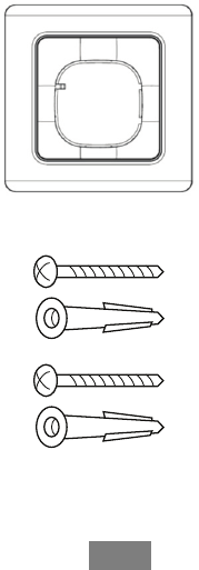
Items Included In Box (Cont.)
A14496
Fig. 3 -- Large Backplate
A14497
Fig. 4 -- Screws and Anchors

8
Items Included In Box (Cont.)
A14498
Fig. 5 -- Installation Instruction, Quick Start Guide, and Wire Labels
Items You Will Need
A. Phillips screwdriver
B. Drill for drilling holes for the mounting anchors with a 3/16”
drill bit.
Before You Start
Review the all the instructions before you start to ensure that there are
no surprises during installation.
9
Step 1. Power Off the HVAC System
ELECTRICAL OPERATION HAZARD
Failure to follow this warning could result in injury or death.
Before installing thermostat, turn off all power to equipment.
There may be more than one power disconnect.
!WARNING
Power off the HVAC system either by a switch at the indoor furnace or
fan coil or at the circuit breaker box.
Verify that the equipment is off by attempting to adjust the temperature
with the existing thermostat. The thermostat may show the temperature
change but your cooling or heating should not come on.
10
Step 2. Remove Existing Thermostat
Remove the cover from your old thermostat. Most snap off easily but
some may be attached by screws.
Note: If the old thermostat has 110/120V wires connected to the
thermostat, it is a high voltage system and is not compatible with this
thermostat.
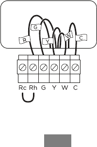
Look at the wires coming out of the wall. Using the old thermostat
base as a guide, use provided labels to label each wire coming out of
thewall(SeeFig.6).
A14499
Fig. 6 -- Label Thermostat Wire
11
Discard any jumper wires between Rh, Rc, or R. This thermostat does
not need them. They are jumpered internally.
When done, remove the old thermostat base by unscrewing it from the
wall. Be careful not to let any wires fall back into the wall.
Discard or recycle old thermostat.
ENVIRONMENTAL HAZARD
Failure to follow this caution may result in environmental
damage.
Mercury is a hazardous waste. Federal regulations require that
mercury be disposed of properly.
CAUTION
!
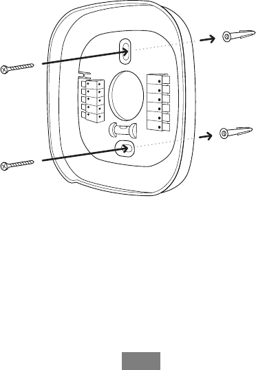
Step 3. Attach Backplate to Wall
Position the backplate, ensuring that it is straight by checking the
bubble on the built--in level. Mark the mounting holes on the wall with
a pencil.

12
Installing the optional large backplate
If the small backplate doesn’t cover the marks left by the previous
thermostat, attach the larger backplate instead.
Remove the center piece from the small backplate by gently pushing
the snap and pulling toward you.
Insert the center piece into the large backplate, using the tabs on the
right as a guide. It will snap into place when correctly inserted.
Secure the backplate
Drill mounting holes on the pencil marks with a 3/16” drill bit.
Insert the plastic drywall anchors into the wall.
Use the screws provided to secure the backplate to the wall. (See Fig.
7)
13
A14500
Fig. 7 -- Secure Backplate to Wall

14
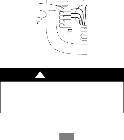
Step 4. Connect the Wiring
The wires from the wall should plug easily into the terminal blocks.
Adjust length and routing of each wire to reach proper terminal and
connector block on mounting base with 1/4--in. (6 mm) of extra wire.
Strip only 1/4 in. of insulation from each wire to prevent adjacent
wires from shorting together when connected. Only one wire can fit
into each terminal block location. Do not try to force two wires into a
terminal block location, it might damage the terminal block or not
fully engage the wires.
When installed correctly, the release lever of the terminal block will
lower to indicate engagement. To release a wire, press down on the
lever. (See Fig. 8)
Match and connect equipment wires to proper terminals of the
connector blocks. If there are separate 24VAC transformers, one in the
indoor unit and one in the outdoor unit, connect the common to the
respective C terminals. Connect the R from the indoor unit to the Rh
terminal. Connect the R from the outdoor unit to the Rc terminal. Then
the W signal is taken from the Rh power and the Y/Y1, Y2, G and O/B
signals are taken from the Rc power.
15
Rc
G
Y1
W1
(AUX1)
O/B
A14501
Fig. 8 -- Terminal Block Release Lever
ELECTRICAL OPERATION HAZARD
Failure to follow this warning could result in injury or death.
Before installing thermostat, turn off all power to equipment.
There may be more than one power disconnect.
!WARNING
If you need help with the wiring, refer to the wiring diagrams at the
back of this guide.

16
System wiring diagrams covered are:
dConventional heating and cooling systems
dHeat pumps (air or geothermal)
dBoilers or radiant heat systems
dAccessory devices: dehumidifiers, humidifiers, or ventilators
Attach thermostat
Push any excess wires back into the wall, and connect the thermostat
to the backplate.
Step 5. Power On the HVAC System
Power back on the HVAC equipment. The thermostat will
automatically power on. It is recommended to have the homeowner’s
Wi--Fi password handy in order to complete setup.
Follow the on--screen instructions. The thermostat software will guide
you through the setup, which includes:
dEquipment configuration (HVAC and accessories)
dSetting preferences
dConnectingtoWi--Fi
dRegistering the thermostat to the online web portal
NOTE: The settings can be changed at any time from the menus.
Congratulations, you’re done!

17
TROUBLESHOOTING
If your thermostat does not power on, please check the following:
1. Check that all wires are properly inserted into the terminal blocks at
the thermostat. Tug lightly on the wires to ensure they are not loose.
2. Ensure you turned the power back on to the equipment either the
switch at the indoor equipment or the electrical panel (where you orig-
inally turned off the equipment).
3. If your device still doesn’t power on check the AC voltage between
Rc and C or Rh and C and ensure it is 24V AC.
FEATURES
The Carrier Côr thermostat has a touch screen and interface similar to
that used in smart phones.
Accessing your web portal
Register the Carrier Côr thermostat at www.Carrier.com/myhome to
control it from your smartphone, tablet or desktop, and to access free
online energy management tools.
Downloading the app
Control the thermostat from your smart phone. The thermostat
supports both iOS and Android devices. Find the app at
www.Carrier.com/myhome.
18
WIRING DIAGRAMS
The following pages provide wiring diagrams for common HVAC
equipment configurations.
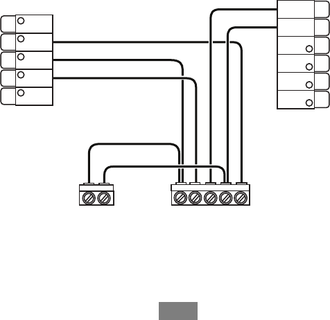
Single Stage Cooling and Heating System
AC
YC
Furnace
YWRCG
Rc
G
Y/Y1
W/W1
(AUX1)
O/B
ACC–
ACC+
W2
(AUX2)
Y2
C
R
H
A14502
Fig. 9 -- Air Conditioner-- Single Stage (Heat / Cool)
19
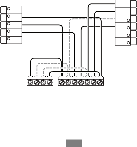
WIRING DIAGRAMS (Cont.)
Furnace
Two Stage Cooling and/or Heating System
AC
Y1 Y2 C
Furnace
Y1 Y/Y2 W1 W2 R C G
Rc
G
Y/Y1
W/W1
(AUX1)
O/B
ACC–
ACC+
W2
(AUX2)
Y2
C
R
H
R
A14502B
Fig. 10 -- Air Conditioner-- Two Stages each (Heat / Cool)
20
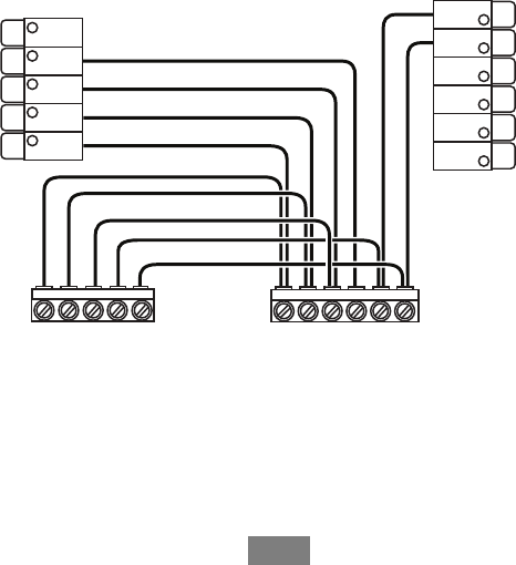
WIRING DIAGRAMS (Cont.)
Heat Pump Fan Coil or Furnace
Single Stage Heat Pump and Auxiliary Heat
W2
O/B YRCW
O/B* YGRC
Rc
G
Y/Y1
W/W1
(AUX1)
O/B ACC–
ACC+
W2
(AUX2)
Y2
C
R
H
* Connect to O/B terminal on furnace ir fan coil, if available
A14503
Fig. 11 -- Heat Pump (Air or Geothermal) With Auxiliary Heat--
Single Stage
21
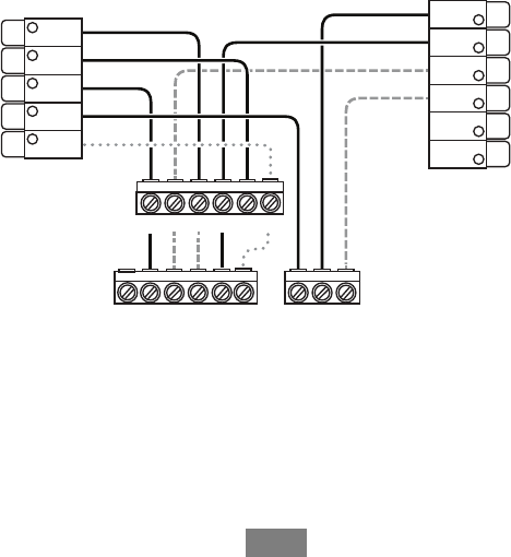
WIRING DIAGRAMS (Cont.)
Heat Pump Fan Coil or Furnaces
Stage 2 Heat Pump and Auxiliary Heat
W2W1O/B Y1 Y2 R C W1O/B* W2 Y1 GY/Y2 R C
Rc
G
Y/Y1
W/W1
(AUX1)
O/B
ACC–
ACC+
W2
(AUX2)
Y2
C
R
H
* Connect to O/B terminal on furnace ir fan coil, if available
A14503B
Fig. 12 -- Heat Pump (Air or Geothermal) With Auxiliary Heat--
Two Stages
22
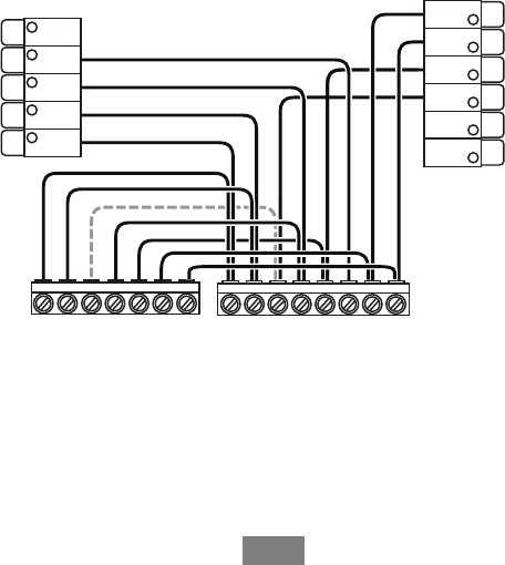
WIRING DIAGRAMS (Cont.)
Air Conditioner
or Heat Pump
Boiler
Stage 2 Heat and Cool (If Applicable)
*Reversing Valve for Heat Pumps Only
Rc
G
Y/Y1
W/W1
(AUX1)
O/B
ACC–
ACC+
W2
(AUX2)
Y2
C
R
H
Y1 Y2 RCG
Y2Y1 C O/B* W1 W2R
Air Handler
O/B
R
W1**
**Do not connect W1 at HP (set enabled w/ defrost)
A14504
Fig. 13 -- Boiler or Radiant System With Fan Coil
and Conventional Cooling or Heat Pump
23
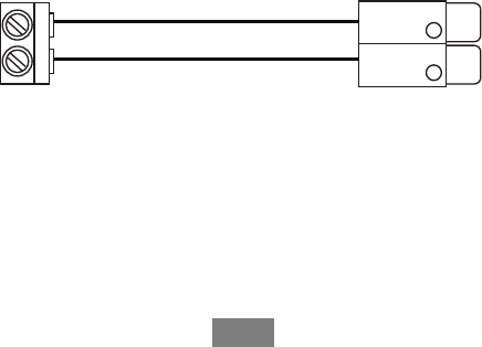
WIRING DIAGRAMS (Cont.)
Accessory Devices
The thermostat can control an accessory HVAC device like a
humidifier, dehumidifier, or ventilation device from its dry contact
ACC terminals (The ACC terminals do not provide 24V AC output).
If the accessory is internally powered, connect the 24V to ACC+. Also
connect the common for the accessory to common on the control
board.
Accessory Device Thermostat Terminals
Only needed if your accessory device is self-powered.
Note: You will need to congure the accessory device when you rst power
on your thermostat.
ACC-
ACC+
24V
C
A14505
Fig. 14 -- Accessory Device Connection

24
Approvals
This product was designed and built in accordance to RoHS directive
2002/95/EC and contains no hazardous substances as defined by this
directive.
FCC Compliance Commission (FCC)
Compliance Statement:
This equipment has been tested and found to comply with the limits
for a Class B digital device, pursuant to part 15 of the FCC Rules.
These limits are designed to provide reasonable protection against
harmful interference in a residential installation. This equipment
generates, uses and can radiate radio frequency energy and, if not
installed and used in accordance with the instructions, may cause
harmful interference to radio communications. However, there is no
guarantee that interference will not occur in a particular installation. If
this equipment does cause harmful interference to radio or television
reception, which can be determined by turning the equipment off and
on, the user is encouraged to try to correct the interference by one or
more of the following measures:
dReorient or relocate the receiving antenna.
dIncrease the separation between the equipment and receiver.

25
dConnect the equipment into an outlet on a circuit different from
that to which the receiver is connected.
dConsult the dealer or an experienced radio/TV technician for
help. This device complies with part 15 of FCC rules. Opera-
tion is subject to the following two conditions:
1. This device may not cause harmful interference.
2. This device must accept any interference received, including
interference that may cause undesired operation.
Change or modifications that are not expressly approved by the
manufacturer could void the user’s authority to operate the equipment.
RF Exposure Information
This equipment complies with FCC radiation exposure limits set forth
for an uncontrolled environment. In order to avoid the possibility of
exceeding the FCC radio frequency exposure limits, human proximity
to the antenna shall not be less than 20cm during normal operation.
Industry Canada (IC)
Compliance Notice:
This device complies with Industry Canada license--exempt RSS
standard(s). Operation is subject to the following two conditions:
1. this device may not cause interference, and

26
2. this device must accept any interference, including interference
that may cause undesired operation of the device.
Le présent appareil est conforme aux CNR d’Industrie Canada
applicable aux appareils radio exempts de licence. L’exploitation est
autorisée aux deux conditions suivantes:
1. l’appareil ne doit pas produire de brouillage, et
2. l’utilisateur de l’appareil doit accepter tout brouillage ra-
dioélectrique subi, même si le brouillage est susceptible d’en
compromettre le fonctionnement.
This Class B digital apparatus complies with Canadian ICES--003.
Cet appareil numérique de la classe B est conforme à la norme NMB--
003 du Canada.
Industry Canada (IC)
Radiation Exposure Statement:
This equipment complies with IC RSS--102 radiation exposure limits
set forth for an uncontrolled environment. This equipment should be
installed and operated with minimum distance 20cm between the
radiator & your body.

27
Notes

www.Carrier.com/myhome S1--800--CARRIER
Copyright 2014 Carrier Corp. S7310 W. Morris St. SIndianapolis, IN 46231
Edition Date: 10/14
Manufacturer reserves the right to change, at any time, specifications
and designs without notice and without obligations. R e p l a c e s : T P --- W E M --- 0 1 S I
C a t a l o g N o : T P --- W E M --- 0 2 S I